fundamentals of wimax - a technology primer - frank...
TRANSCRIPT

Telesystem Innovations Inc. 18 Byer Drive Phone +1.416.294.7211
Markham, ON Fax +1.416.969.9570
L3P 6V7 Canada
Fundamentals of WiMAX:
A Technology Primer

Table of Content
WiMAX Overview ...........................................................................................................................................1
WiMAX in the IEEE and WiMAX Forum...................................................................................................1
WiMAX Technology Overview ................................................................................................................2
Certification Naming Conventions ..........................................................................................................4
Mobile WiMAX Reference Architecture.........................................................................................................7
Network Architecture Reference Points .................................................................................................7
Inter-ASN Reference Points..............................................................................................................7
Intra-ASN Reference Points..............................................................................................................7
Access Service Network Profiles .............................................................................................................7
Profile A ...........................................................................................................................................8
Profile B............................................................................................................................................9
Profile C..........................................................................................................................................10
Throughput Performance of Mobile WiMAX ...............................................................................................13
Physical Layer (PHY) Throughput Performance ....................................................................................13
Layer 2 (MAC) Throughput Performance..............................................................................................15
WiMAX System Gain and Link Budget..........................................................................................................19
WiMAX System Parameters..................................................................................................................19
WiMAX Link Budget ..............................................................................................................................20
Erceg Path Loss Model ..........................................................................................................................22
Quality of Service in WiMAX Networks ........................................................................................................24
WiMAX Medium Access Control Layer – A QoS Perspective................................................................24
Connections and Service Flows......................................................................................................25
MAC Convergence Sublayer...........................................................................................................26
MAC Common Parts Sublayer........................................................................................................27
Scheduling Services...............................................................................................................................28
End-to-End Quality of Service ...............................................................................................................29
WiMAX Usage Scenarios and Applications...................................................................................................31
WiMAX Usage Scenarios.......................................................................................................................31
Private Networks ...........................................................................................................................31
Banking Networks..........................................................................................................................31
Education Networks.......................................................................................................................32
Public Safety...................................................................................................................................32
Offshore Communications.............................................................................................................32
Campus Connectivity .....................................................................................................................32
Temporary Construction Communications....................................................................................33
Theme Parks ..................................................................................................................................33
Public Networks.............................................................................................................................33
Wireless Service Provider Access Network ....................................................................................33
Application Requirements.....................................................................................................................34

© 2010 Telesystem Innovations Inc. All rights reserved. - 1 -
1 WiMAX Overview
WiMAX in the IEEE and WiMAX Forum
WiMAX (worldwide interoperability for microwave access) is the commercial name for products
based on the IEEE 802.16 standard as trade marked by the WiMAX Forum, an association of
companies representing the ecosystem of the WiMAX technology.
The Institute of Electrical and Electronics Engineers (IEEE) is the main body responsible for defining
the protocol on which the WiMAX technology is based. IEEE 802 LAN/WAN Standard Committee
develops Local Area Network and Metropolitan Area Network standards. The IEEE has designated
the number 802.16 for broadband wireless access on which WiMAX is based.
While the IEEE standard defines the air interface, the WiMAX Forum has undertaken the task of
defining the complete end-to-end network architecture and specifying the system profile to
ensure worldwide interoperability of WiMAX equipment. The WiMAX Forum also undertakes the
task of certifying vendor equipment as compliant with standard specifications in conjunctions with
selected test and certification laboratories.
At the current moment, there are two commercial versions of WiMAX: Fixed WiMAX based on
IEEE 802.16d (or 802.16-2004, approved in June 2004) and Mobile WiMAX based on IEEE 802.16e-
2005 (ratified in December 2005). Mobile WiMAX can be used in both fixed and mobile scenarios
while Fixed WiMAX does not support mobility features.
Mobile WiMAX is a feature rich technology with many aspects for improvements. The current
Mobile WiMAX systems are based on so called “Release 1.0 system profile.” There is also a follow
on release “Release 1.5 system profile” which includes additional features not available in Release
1.0 such as Frequency Domain Duplexing (FDD) and uplink MIMO (multiple input multiple output)
functionality. Release 2.0 system profile is based on a new iteration of the IEEE standard –
802.16m – which is planned to be completed by the end of 2010.
Mobile WiMAX is the mainstream technology adopted by numerous wireless access service
providers and supported by equipment vendors whereas the Fixed WiMAX standard has limited
deployment and support within the larger WiMAX ecosystem.

© 2010 Telesystem Innovations Inc. All rights reserved. - 2 -
Figure 1 WiMAX enables a variety of applications and usage scenarios in the same network.
WiMAX Technology Overview
WiMAX is generally considered a fourth generation (4G) wireless access technology that provides
significant advancement in throughput over existing wireless access technologies. These
advancements are made possible because WiMAX implements the following technologies which
are common with other 4G wireless access systems (most notably Long Term Evolution – LTE):
1- Orthogonal Frequency Division Multiple Access (OFDMA): WiMAX uses a side frequency
channel to transmit and receive information, typically 3.5 – 10 MHz wide, depending on the
frequency band and system profile. The signal is transmitted over multiple frequency-domain
orthogonal carriers which make up the frequency channel. Mobile WiMAX uses 512 or 1024
carriers, depending on the channel. The carriers are orthogonal in the frequency domain as to
limit intersymbol interference: time domain representation allows constraining interference
to a short guard interval at the beginning of each symbol resulting which increases the
robustness of time-dispersive radio channels. Advancements in OFDMA technology are made
possible by the ability to perform inverse Fourier Transform operation at low cost (small size
and low power consumption) by modern microelectronic processors. Hence, advancements
in silicon technologies and the ability to condense higher processing power in ever smaller die
at lower power consumptions made possible the implementation of modulation techniques
known as early as the 1960’s. In WiMAX, users share the frequency domain by allocating
different carriers to different users. Users also share the time domain as they are scheduled
for transmit and receive functions in their order during a 5 msec frame. Mobile WiMAX is
based on Time Domain Duplex where the same frequency is used for transmit and receive
operation. Other advantages of the OFDM technology include low-complexity receiver design
which does not require frequency-domain equalization and simple combining of multiple
signals from multiple transmitters.
2- Advanced Antenna Systems: Multiple Input Multiple Output (MIMO) techniques were
invented in the 1990’s and came to maturity during the past decade. These techniques take
advantage of signal multipath in wireless communication to increase the capacity of the
transmission channel. In theory, channel capacity is linearly proportional to the minimum

© 2010 Telesystem Innovations Inc. All rights reserved. - 3 -
number of transmit and receive antennas (i.e. Channel Capacity ∝ min (NTx, MRx), where NTx is
the number of transmit antennas and MRx is the number of receive antennas). Hence a 2
transmit and 2 receive antenna system as common in Mobile WiMAX would show a
maximum doubling of the channel throughput (or capacity). In practice, up to 1.5x capacity
gain is achieved. Furthermore, in propagation environments where multipath is absent,
MIMO would have limited to no capacity gain. In this case, as well as in cases where signal
quality is low, a technique called “Space Time Coding” is used to transmit versions of the same
symbol on multiple antennas thereby increasing signal robustness. This technique is often
referred to as MIMO A in Mobile WiMAX whereas the former, capacity enhancing MIMO
mode based on “Spatial Multiplexing” techniques is referred to as MIMO B. The MIMO
techniques are made easier to implement in WiMAX because of its TDD nature where
“channel reciprocity” allows estimating downlink propagation channel coefficients based on
knowledge of the uplink channel (or vice versa). This facilitates implementation of MIMO and
other advanced antenna system techniques and limits the requirement for calibration and
feedback of received signal coefficients to the transmitter.
3- Flat-IP Architecture: WiMAX is based on all IP-platform with no legacy circuit-switched
component as in 3G systems (where data is IP based and voice is circuit switched) as shown in
Figure 2. The IEEE standard only defines layers one and two (physical and medium access
control layers) leaving the higher layers of the protocol stack open to relay on other bodies
like the Internet Engineering Task Force (IETF) to set the standards (e.g. TCP/IP, SIP, IPSec).
This is different from 3G systems where 3GPP (Third Generation Partnership Project) sets the
standard for a wide range of interfaces to ensure inter-vendor and inter-network
interoperability. The WiMAX Forum has setup a Network Working Group (NWG) to address
the issue of standardization over the higher-level networking protocols nevertheless. The flat-
IP architecture reduces the total cost of ownership of the network and reduces the
deployment cycle to allow for faster time-to-market (or time-to-operation) of the network.
These are very compelling features for traditional uses of wireless technologies (e.g. wireless
network operators) as well as emerging uses of broadband systems (e.g. industrial
applications) as expensive dedicated core equipment (e.g. switches) are eliminated in favor of
standard off the shelf routers and switches thereby enabling the tighter integration of the
mobile network with the Internet and other corporate networks.
Figure 2 WiMAX flat, all-IP architecture.
In addition to the three main reasons above, there are a number of key differentiators that
enhance the appeal of WiMAX. Quality of Service mechanisms that support different types of user
applications like Voice over Internet Protocol (VoIP), video transmission and web browsing are but
a few examples. Privacy and Key Management Protocol version 2 (PKMv2) is the basis of WiMAX
security. Authentication is accomplished through different types of Extensible Authentication
Protocol (EAP) such as EAP-TLS (Transport Layer Security) and EAP-SIM (Subscriber Identity
© 2010 Telesystem Innovations Inc. All rights reserved. - 4 -
Module). User data is encrypted with AES-CCM cipher (Advanced Encryption Standard / Counter
with CBC-MAC mode of authentication) with 128 bit keys generated from EAP authentication.
These and other features differentiate WiMAX from 3G technologies as well as from unlicensed
band wireless standards such as WiFi.
Certification Naming Conventions
The WiMAX Forum Certification Working Group (CWG) is responsible for coordinating certification
activities for the WiMAX ecosystem which includes developing the test requirement, cases and
plans, and signing test lab as well as setting the procedures and rules of certification testing. The
CWG in conjunction with the WiMAX Forum Board of Directors and input from the WiMAX vendor
and user community decides on the certification profiles which describe the frequency bands of
operation as well as the channel bandwidth.
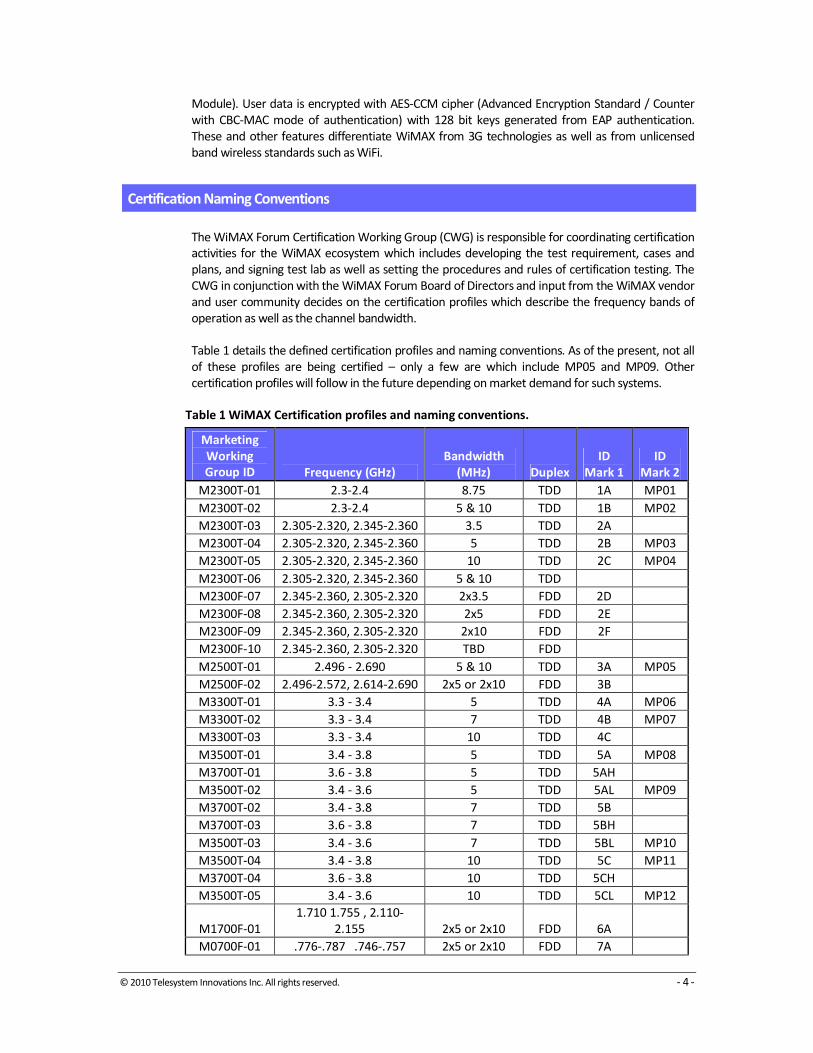
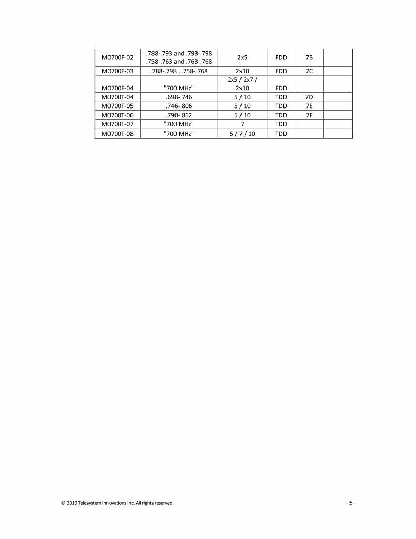
Table 1 details the defined certification profiles and naming conventions. As of the present, not all
of these profiles are being certified – only a few are which include MP05 and MP09. Other
certification profiles will follow in the future depending on market demand for such systems.
Table 1 WiMAX Certification profiles and naming conventions.
Marketing
Working
Group ID Frequency (GHz)
Bandwidth
(MHz) Duplex
ID
Mark 1
ID
Mark 2
M2300T-01 2.3-2.4 8.75 TDD 1A MP01
M2300T-02 2.3-2.4 5 & 10 TDD 1B MP02
M2300T-03 2.305-2.320, 2.345-2.360 3.5 TDD 2A
M2300T-04 2.305-2.320, 2.345-2.360 5 TDD 2B MP03
M2300T-05 2.305-2.320, 2.345-2.360 10 TDD 2C MP04
M2300T-06 2.305-2.320, 2.345-2.360 5 & 10 TDD
M2300F-07 2.345-2.360, 2.305-2.320 2x3.5 FDD 2D
M2300F-08 2.345-2.360, 2.305-2.320 2x5 FDD 2E
M2300F-09 2.345-2.360, 2.305-2.320 2x10 FDD 2F
M2300F-10 2.345-2.360, 2.305-2.320 TBD FDD
M2500T-01 2.496 - 2.690 5 & 10 TDD 3A MP05
M2500F-02 2.496-2.572, 2.614-2.690 2x5 or 2x10 FDD 3B
M3300T-01 3.3 - 3.4 5 TDD 4A MP06
M3300T-02 3.3 - 3.4 7 TDD 4B MP07
M3300T-03 3.3 - 3.4 10 TDD 4C
M3500T-01 3.4 - 3.8 5 TDD 5A MP08
M3700T-01 3.6 - 3.8 5 TDD 5AH
M3500T-02 3.4 - 3.6 5 TDD 5AL MP09
M3700T-02 3.4 - 3.8 7 TDD 5B
M3700T-03 3.6 - 3.8 7 TDD 5BH
M3500T-03 3.4 - 3.6 7 TDD 5BL MP10
M3500T-04 3.4 - 3.8 10 TDD 5C MP11
M3700T-04 3.6 - 3.8 10 TDD 5CH
M3500T-05 3.4 - 3.6 10 TDD 5CL MP12
M1700F-01
1.710 1.755 , 2.110-
2.155 2x5 or 2x10 FDD 6A
M0700F-01 .776-.787 .746-.757 2x5 or 2x10 FDD 7A
© 2010 Telesystem Innovations Inc. All rights reserved. - 5 -
M0700F-02 .788-.793 and .793-.798
.758-.763 and .763-.768 2x5 FDD 7B
M0700F-03 .788-.798 , .758-.768 2x10 FDD 7C
M0700F-04 "700 MHz"
2x5 / 2x7 /
2x10 FDD
M0700T-04 .698-.746 5 / 10 TDD 7D
M0700T-05 .746-.806 5 / 10 TDD 7E
M0700T-06 .790-.862 5 / 10 TDD 7F
M0700T-07 "700 MHz" 7 TDD
M0700T-08 "700 MHz" 5 / 7 / 10 TDD

© 2010 Telesystem Innovations Inc. All rights reserved. - 6 -
2 Mobile WiMAX Reference Architecture
The Network Working Group of the WiMAX Forum has developed the Network Reference Model
(NRM) which identifies the functional entities and reference points over which interoperability is
achieved between the functional entities.
The NRM is divided into three functional entities: the mobile station (MS), the Access Service
Network (ASN) and the Connectivity Service Network (CSN). The Access Service Network includes
the set of functions allowing a WiMAX subscriber access to the radio network. The Connectivity
Service Network is defined as the set of network functions that provide IP connectivity services to a
WiMAX subscriber. Figure 3 shows the network reference model.
The grouping and distribution of functions into physical devices within the functional entities is left
to the equipment vendor to decide as long as the implementation meets the functional and
interoperability requirements. This is leads to different profiles defined by the particular mapping
of the functions to network elements. In one network architecture, the functions are mapped onto
two network elements: The base station (BS) and the ASN Gateway (ASN-GW). Other functional
mappings and network architectures are possible as well.
The base station performs the radio related functions of the ASN: it includes the WiMAX physical
(PHY; Layer 1) and medium access control (MAC; Layer 2) layers. The ASN-GW performs control
functions as well as other functions related to subscriber data such as routing and bridging.
The CSN typically includes the Authentication Authorization and Accounting (AAA) Server, Policy
Control Server, Mobile IP Home Agent (HA), Dynamic Host Configuration Protocol (DHCP) Server,
and other servers and interworking gateways.
Figure 3 Mobile WiMAX Network Reference Model.
© 2010 Telesystem Innovations Inc. All rights reserved. - 7 -
Network Architecture Reference Points
The reference points represent the interface between different functional entities of the WiMAX
Network Reference Model. Protocols run between functional entities across the reference points
which are used as anchors for interoperability testing. There are two types of reference points:
Inter-ASN reference points and Intra-ASN reference points.
Inter-ASN Reference Points
R1: consists mainly of the IEEE 802.16 protocol between the MS and the BS (Layers 1 & 2).
R2: consists of the protocols and procedures between the MS and the CSN mainly associated with
Authentication, Ser-vices Authorization and IP Host Configuration management.
R3: consists of control plane protocols as well as the IP data plane between the ASN and the CSN.
R4: consists of control and data plane procedures between ASNs and ASN Gateways particularly
to support mobility ser-vices.
R5: consists of control and data plane protocols needed to support roaming between the CSN
operated by a home Net-work Service Provider (NSP) and that operated by a visited NSP.
Intra-ASN Reference Points
Decomposing the ASN into base station and ASN GW entities give rise to the following reference
points:
R6: consists of control (e.g. QoS, security, paging and other mobility related protocols) and data
plane protocols between the base station and the ASN-GW.
R7: an optional reference point resulting from the decomposition of the ASN-GW itself into a
decision point and enforcement point functions. The enforcement point includes all data plane
functions while the decision point includes all the non-data plane functions.
R8: an optional reference point that consists of the set of control plane messages between base
stations for handover purposes.
Access Service Network Profiles
An ASN profile defines a particular mapping of functions into base station and ASN GW and
exposes reference points over which protocols and messages are defined. Three basic profiles
have been defined by the WiMAX Forum NWG: Profile A, B, and C. Figure 4 shows a high-level
functional description of these profiles particularly noting the placement of the handover (HO) and
Radio Resource Control (RRC) functions in the network.

© 2010 Telesystem Innovations Inc. All rights reserved. - 8 -
Figure 4 Description of WiMAX access service network profiles.
Profile A
Profile A is essentially a centralized profile where the ASN GW includes both radio dependent and
independent functions. The key features of this profile include the following:
• Handover (HO) Control function is in the ASN GW.
• Radio Resource Control (RRC) function is in the ASN GW that allows Radio Resource
Management (RRM) among multiple base stations.
• ASN Anchored mobility among base stations is achieved by utilizing R6 and R4 physical
connections.

© 2010 Telesystem Innovations Inc. All rights reserved. - 9 -
Figure 5 Profile A Functional Decomposition.
Profile B
Profile B can be qualified as an ASN with unexposed (i.e. proprietary) intra-ASN interfaces: The ASN
is a black-box where intra-ASN interoperability is not specified. Furthermore, mapping of the ASN
functions is not specified which results in different realizations of Profile B implementation. Hence,
it is possible to arrive at an implementation where all the ASN functions are located within a single
physical device (namely the base station) or an implementation where the functions are spread
over multiple physical devices.
Profile B ASNs must be capable of interoperating with other ASNs of any profile over the R3 and R4
reference points to enable multi-ASN networks.
* ASN Anchored Mobility shall be possible over R6 and R4
* Support for this function is optional.
ASN
ASN-GW
BS
R3
R4*
Data Path Fn(Type 1 - Default, OR
Type 2 - Optional)
Handover
Function
Context
Function
PMIP Client
AAA Client
Location
Register
MIP FA
Authenticator
Key
Distributor
DHCP
Proxy/Relay
Service Flow
Auth.
RRC
Paging
Controller
Data Path Fnc.(Type 1 - Default, OR
Type 2 - Optional)
Handover
Function
Service Flow Mgmt.
Context
Function
Paging
Agent
RRA
Auth. Relay
Key Receiver
R6
© 2010 Telesystem Innovations Inc. All rights reserved. - 10 -
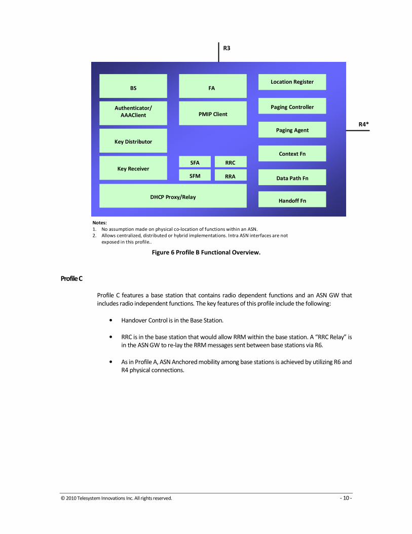
Figure 6 Profile B Functional Overview.
Profile C
Profile C features a base station that contains radio dependent functions and an ASN GW that
includes radio independent functions. The key features of this profile include the following:
• Handover Control is in the Base Station.
• RRC is in the base station that would allow RRM within the base station. A “RRC Relay” is
in the ASN GW to re-lay the RRM messages sent between base stations via R6.
• As in Profile A, ASN Anchored mobility among base stations is achieved by utilizing R6 and
R4 physical connections.
Notes:
1. No assumption made on physical co-location of functions within an ASN.
2. Allows centralized, distributed or hybrid implementations. Intra ASN interfaces are not
exposed in this profile..
BS
Authenticator/
AAAClient
Key Distributor
Key Receiver
DHCP Proxy/Relay
SFA RRC
SFM RRA
PMIP Client
FALocation Register
Paging Controller
Paging Agent
Context Fn
Data Path Fn
Handoff Fn
R3
R4*

© 2010 Telesystem Innovations Inc. All rights reserved. - 11 -
Figure 7 Profile C Functional Decomposition.
* ASN Anchored Mobility shall be possible over R6 and R4
ASN
ASN-GW
BS
R3
R4*
Data Path Function(Type 1)
Handover Function
(Relay)
Context
Function
PMIP Client
AAA Client
Authenticator
Key
Distributor
DHCP
Proxy/Relay
Srv. Flow
Auth.
MIP FA
Data Path Function(Type 1)
Handover
Function
Srv. Flow Mgnt.
Context
Function
RRC
RRA
Auth. Relay
Key Receiver
R6
Paging
Controller
Location
Register
RRM Relay
© 2010 Telesystem Innovations Inc. All rights reserved. - 12 -
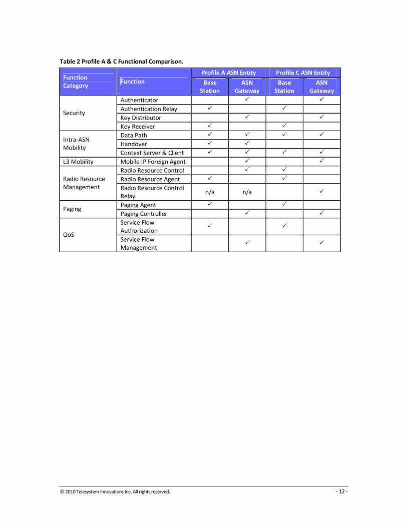
Table 2 Profile A & C Functional Comparison.
Profile A ASN Entity Profile C ASN Entity Function
Category Function Base
Station
ASN
Gateway
Base
Station
ASN
Gateway
Authenticator � �
Authentication Relay � �
Key Distributor � � Security
Key Receiver � �
Data Path � � � �
Handover � � Intra-ASN
Mobility Context Server & Client � � � �
L3 Mobility Mobile IP Foreign Agent � �
Radio Resource Control � �
Radio Resource Agent � � Radio Resource
Management Radio Resource Control
Relay n/a n/a �
Paging Agent � � Paging
Paging Controller � �
Service Flow
Authorization � �
QoS Service Flow
Management � �

© 2010 Telesystem Innovations Inc. All rights reserved. - 13 -
3 Throughput Performance of Mobile WiMAX
Physical Layer (PHY) Throughput Performance
The PHY layer throughput indicates the aggregate data rate transferred over the air which includes
overhead from higher layers. The PHY throughput is an upper limit on the expected throughput of
a system.
Throughput for Mobile WiMAX which is based on the Scalable OFDMA (S-OFDMA) PHY of the IEEE
802.16e-2005 standard will depend on the permutation mode (PUSC, FUSC, AMC, etc.). Here, we
focus on the PUSC mode which is the standard profile.
OFDMA divides the channel bandwidth into a number of sub-carriers. In S-OFDMA, the carrier
spacing is constant, therefore, the number of carriers increase the wider the channel bandwidth. S-
OFDMA supports 128, 512, 1024 or 2048 carriers, of which 512 and 1024 are most common as
they are part of the Mobile WiMAX system profile.
Figure 8 shows a description of the sub-carrier space constituting a frequency channel. Sub-
carriers include null sub-carriers at the edges of the channel for guard band purpose, pilot carriers
used for channel estimation and corrections resulting from mobility (e.g. phase noise), and data
sub-carriers used to carry management and traffic data. Table 3 shows the utilization of carriers in
Mobile WiMAX. Note that 3.5 MHz channel bandwidth is not part of the IEEE 802.16e-2005
standard for the S-OFDMA PHY, but may be supported by some base station vendors. Also, there
are a higher number of pilot sub-carriers for the uplink (mobile to base station) path which is
designed to provide better correction for effects of mobility on the uplink communication channel.
Figure 8 Scalable-OFDMA Sub-carrier structure.
Based on the sub-carrier space, a number of parameters for the S-OFDMA PHY can be derived.
These parameters are shown in Table 4 for a frame of 5 msec and cyclic prefix of 1/8 as per the
Mobile WiMAX System Profile.

© 2010 Telesystem Innovations Inc. All rights reserved. - 14 -
Table 3 Utilization of carriers in Mobile WiMAX.
Bandwidth (MHz) 3.5 7 5 10
Total Sub-Carriers 512 1024 512 1024
Path DL UL DL UL DL UL DL UL
Used Carriers 420 408 840 840 420 408 840 840
Data Carriers 360 272 720 560 360 272 720 560
Pilot Carriers 60 136 120 280 60 136 120 280
Null Carriers 92 104 184 184 92 104 184 184
Sub-channels 15 17 30 35 15 17 30 35
Table 4 also shows the total number of symbols available for control and data traffic in an S-
OFDMA frame. These symbols are assigned to the downlink (base station to mobile) or uplink
path. The maximum number of symbols for 3.5 and 7 MHz channels is 33, while for 5 and 10 MHz
channels it is 47. We have already accounted for the transition gaps between the downlink and
uplink symbols in RTG and TTG. Figure 9 shows the frame structure for Mobile WiMAX.
Table 4 Key parameters for the S-OFDMA PHY in PUSC mode.
Mode 802.16e S-OFDMA PHY; PUSC Permutation
Bandwidth (MHz) 3.5 7 5 10
Sampling Factor 8/7 8/7 28/25 28/25
FFT Size 512 1024 512 1024
Sampling Frequency (MHz) 4 8 5.6 11.2
Sample Time (msec) 250 125 178.6 89.3
Sub-carrier Frequency Spacing (kHz) 7.8 7.8 10.9 10.9
Useful Symbol Time (msec) 128 128 91.4 91.4
Cyclic Prefix 1/8 1/8 1/8 1/8
Guard Time (msec) 16 16 11.4 11.4
OFDMA Symbol Time (msec) 144 144 102.9 102.9
Frame Length (msec) 5 5 5 5
Symbols/Frame 33 33 47 47
RTG (msec) 60 60 60 60
TTG (msec) 188 188 106 106

© 2010 Telesystem Innovations Inc. All rights reserved. - 15 -
Figure 9 Mobile WiMAX Scalable OFDMA frame structure and channelization (Release 1.0).
The throughput rates can be calculated from the number of available data carriers and the number
of symbols in each sub-frame. Table 5 shows the throughput rate per modulation coding scheme
(MCS) for a 60:40 traffic ratio (20:13 and 28:19 DL:UL symbols for 3.5/7 MHz and 5/10 MHz
channels, respectively). Note that 64QAM is not part of the Mobile WiMAX System Profile but
may be supported by certain base station vendors.
Table 5 Physical layer throughput (Mbps) for PUSC mode assuming 60:40 traffic ratio.
Bandwidth (MHz) 3.5 7 5 10
Modulation \ Path DL UL DL UL DL UL DL UL
BPSK ½ 0.7 0.4 1.4 0.7 1 0.5 2 1.1
QPSK ½ 1.4 0.7 2.9 1.5 2 1 4 2.1
QPSK ¾ 2.2 1.1 4.3 2.2 3 1.6 6 3.2
16QAM 1/2 2.9 1.4 5.8 2.9 4 2.1 8.1 4.3
16QAM 3/4 4.3 2.1 8.6 4.4 6 3.1 12.1 6.4
64QAM 2/3 5.8 2.8 11.5 5.8 8.1 4.1 16.1 8.5
64QAM 3/4 6.5 3.2 13 6.6 9.1 4.7 18.1 9.6
64QAM 5/6 7.2 3.5 14.4 7.3 10.1 5.2 20.2 10.6
We can add the downlink and uplink rates to find the total throughput supported by Mobile
WiMAX physical layer.
Layer 2 (MAC) Throughput Performance
Medium Access Control (MAC) layer rate factor control overhead into the throughput
performance. From Figure 9, each frame starts with a preamble symbol used for synchronization

© 2010 Telesystem Innovations Inc. All rights reserved. - 16 -
and downlink channel estimation. This is followed by a frame control header (FCH) which provides
information to decode the MAP messages that follow (e.g. sub-channels used by the sector in the
current frame, coding and length of the subsequent DL-MAP message, etc. The MAP messages
indicate the resource allocation (user data bursts) for the downlink and uplink sub-frames.
UL sub-frame starts with the uplink control channels: CQICH, ACKCH and Ranging Channels. The
CQICH and ACK channels is used for transmitting channel state information and ACK information
from mobile stations to the base station, respectively. The ranging channel is used for various
types of ranging (initial, refresh, and reentry).
The control overhead consists of fixed and variable parts. The fixed part includes the preamble,
FCH, and control channels. The variable part includes the DL-MAP and UL-MAP which also consist
of a fixed and a variable part. The DL-MAP and UL-MAP contain as many Information Elements (IE)
as the number of data bursts. Each IE has a one-to-one correspondence to a user data burst. Table
6 shows an accounting of the size of the fixed allocation for DL-MAP and UL-MAP. Table 7 shows
the accounting for the DL-MAP-IE and UL-MAP-IE.
Table 6 Fixed allocation of DL-MAP and UL-MAP.
DL-MAP Bits
Management Message Type 8
PHY SYNC. Field 32
DCD Count 8
Base Station ID 48
Number of OFDMA Symbol 8
Nibble Padding (if needed) 4
Total DL-MAP 104
UL-MAP
Management Message Type 8
Uplink Channel ID 8
UCD Count 8
Alloc. Start Time 32
No. of OFDMA Symbol 8
Nibble Padding 4
Total UL-MAP 64
The CID is the connection identifier that uniquely determines a connection between a base station
and a mobile station in one direction. The N_CID is the number of CIDs in the corresponding burst
(N_CID = 1 in the example above). Each burst can contain more than one CIDs. DIUC/UIUC
(Downlink/Uplink Interval Usage Code) indicates the usage information of the corresponding burst
(e.g., modulation and coding schemes used). The OFDMA Symbol offset is the offset for the
symbol at which the burst starts (measured in symbols). The sub-channel offset is the lowest index
OFDMA sub-channel used for carrying the burst, starting from sub-channel 0. The boosting field
indicates whether the sub-carriers for this allocation are power boosted. For example, 000 means
no power boost, 001 means +6dB, etc. The number of OFDMA symbols is the number of symbols
that are used to carry the burst. Similarly, the number of sub-channels is the number of sub-
channels that are used to carry the burst. The repetition coding indicates how many times the
code is repeated. For example, 00 means no repetition, 01 means two, 10 means 4, and 11 means
6 repetitions.

© 2010 Telesystem Innovations Inc. All rights reserved. - 17 -
Table 7 Size of DL-MAP-IE and UL-MAP-IE.
DL-MAP_IE Bits
CID 16
N_CID 8
DIUC 4
OFDMA Symbols Offset 8
Sub-channel Offset 6
Boosting 3
Number of OFDMA Symbols 7
Number of sub-channels 6
Repetition Coding Indicator 2
Total DL-MAP_IE 60
UL-MAP_IE
CID 16
UIUC 4
Duration 10
Repetition Coding Indicator 2
Total UL-MAP_IE 32
Based on the above, the size of the MAP messages depends on the number of users active on a
sector and the size will be as follows:
DL-MAP: 104 + N * DL-MAP_IE bits
UL-MAP: 64 + N* UL-MAP_IE bits
Since the MAPs carry critical information, all the mobile stations in the cell are supposed to decode
them correctly. To make sure that even the mobile stations near the cell boundary decode the
MAPs correctly, the coding overhead is rather high for the MAP data. In case of Mobile WiMAX,
these parts are encoded with MCS QPSK 1/2 with 4 repetitions. Therefore, effective data rate is
1/8. Depending on the frequency reuse, repetition 6 may have to be used (e.g. frequency reuse of
1). Because of this, the MAP overhead can be quite a big portion of a WiMAX frame. For an
effective coding rate of 1/8 over QPSK (2 bits) coding, each symbol can carry only 90 or 180 bits for
3.5/5 MHz and 7/10 MHz channels, respectively (360 or 720 carriers * 2 bits * 1/8).
In all, common estimates for MAC layer overhead are at 8 symbols for the downlink sub-frame and
3 symbols for the uplink sub-frame.
Table 8 shows an example of MAC layer throughput considering 8 symbols of overhead for the
downlink sub-frame and 3 symbols for Mobile WiMAX in PUSC mode with 60:40 traffic ratio
(including CP of 1/8 and frame length if 5 msec).

© 2010 Telesystem Innovations Inc. All rights reserved. - 18 -
Table 8 MAC layer throughput for Mobile WiMAX (SISO/MIMO A mode) assuming 8 DL and
3 UL symbol overhead.
Bandwidth (MHz) 3.5 7 5 10
Modulation / Path DL UL DL UL DL UL DL UL
BPSK ½ 0.4 0.3 0.9 0.6 0.7 0.4 1.4 0.9
QPSK ½ 0.9 0.5 1.7 1.1 1.4 0.9 2.9 1.8
QPSK ¾ 1.3 0.8 2.6 1.7 2.2 1.3 4.3 2.7
16QAM ½ 1.7 1.1 3.5 2.2 2.9 1.7 5.8 3.6
16QAM ¾ 2.6 1.6 5.2 3.4 4.3 2.6 8.6 5.4
64QAM 2/3 3.5 2.2 6.9 4.5 5.8 3.5 11.5 7.2
64QAM ¾ 3.9 2.4 7.8 5 6.5 3.9 13 8.1
64QAM 5/6 4.3 2.7 8.6 5.6 7.2 4.4 14.4 9
© 2010 Telesystem Innovations Inc. All rights reserved. - 19 -
4 WiMAX System Gain and Link Budget
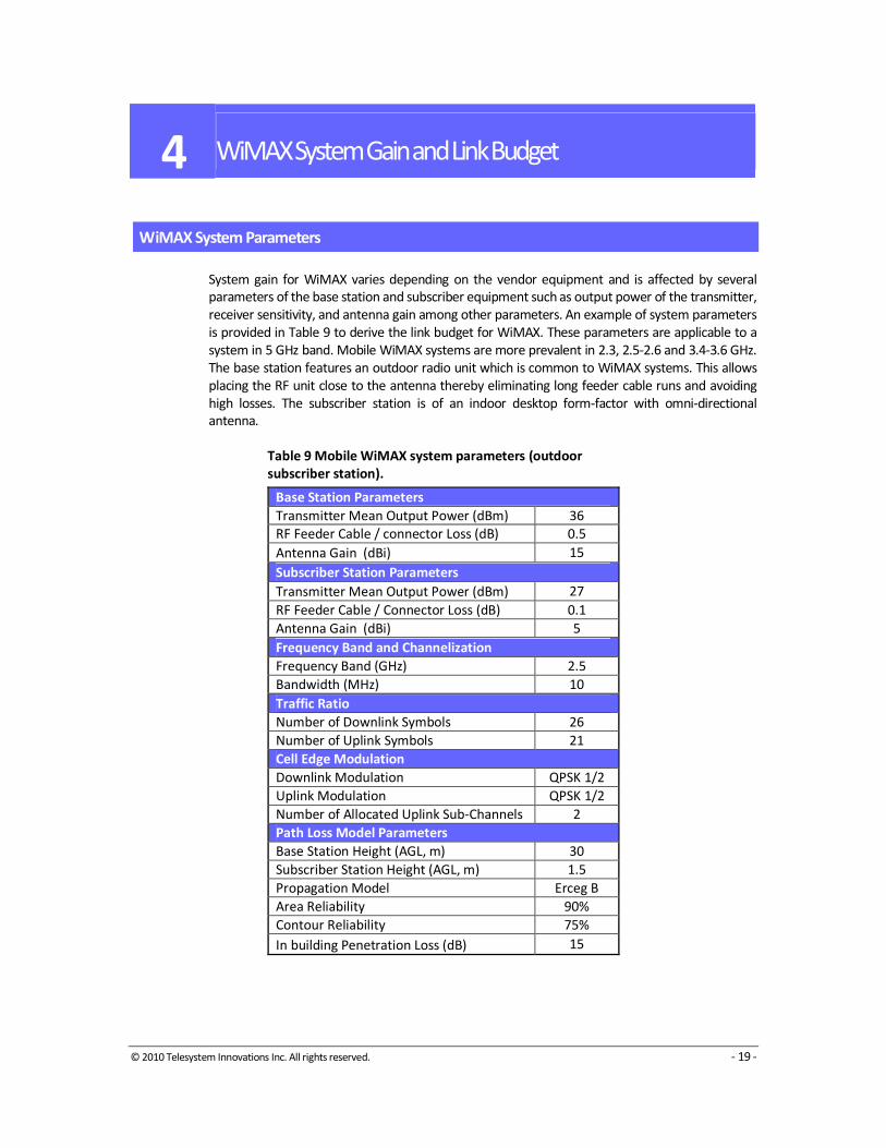
WiMAX System Parameters
System gain for WiMAX varies depending on the vendor equipment and is affected by several
parameters of the base station and subscriber equipment such as output power of the transmitter,
receiver sensitivity, and antenna gain among other parameters. An example of system parameters
is provided in Table 9 to derive the link budget for WiMAX. These parameters are applicable to a
system in 5 GHz band. Mobile WiMAX systems are more prevalent in 2.3, 2.5-2.6 and 3.4-3.6 GHz.
The base station features an outdoor radio unit which is common to WiMAX systems. This allows
placing the RF unit close to the antenna thereby eliminating long feeder cable runs and avoiding
high losses. The subscriber station is of an indoor desktop form-factor with omni-directional
antenna.
Table 9 Mobile WiMAX system parameters (outdoor
subscriber station).
Base Station Parameters
Transmitter Mean Output Power (dBm) 36
RF Feeder Cable / connector Loss (dB) 0.5
Antenna Gain (dBi) 15
Subscriber Station Parameters
Transmitter Mean Output Power (dBm) 27
RF Feeder Cable / Connector Loss (dB) 0.1
Antenna Gain (dBi) 5
Frequency Band and Channelization
Frequency Band (GHz) 2.5
Bandwidth (MHz) 10
Traffic Ratio
Number of Downlink Symbols 26
Number of Uplink Symbols 21
Cell Edge Modulation
Downlink Modulation QPSK 1/2
Uplink Modulation QPSK 1/2
Number of Allocated Uplink Sub-Channels 2
Path Loss Model Parameters
Base Station Height (AGL, m) 30
Subscriber Station Height (AGL, m) 1.5
Propagation Model Erceg B
Area Reliability 90%
Contour Reliability 75%
In building Penetration Loss (dB) 15
© 2010 Telesystem Innovations Inc. All rights reserved. - 20 -
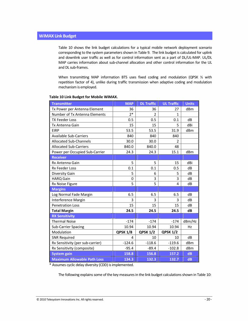
WiMAX Link Budget
Table 10 shows the link budget calculations for a typical mobile network deployment scenario
corresponding to the system parameters shown in Table 9. The link budget is calculated for uplink
and downlink user traffic as well as for control information sent as a part of DL/UL-MAP. UL/DL
MAP carries information about sub-channel allocation and other control information for the UL
and DL sub-frames.
When transmitting MAP information BTS uses fixed coding and modulation (QPSK ½ with
repetition factor of 4), unlike during traffic transmission when adaptive coding and modulation
mechanism is employed.
Table 10 Link Budget for Mobile WiMAX.
Transmitter MAP DL Traffic UL Traffic Units
Tx Power per Antenna Element 36 36 27 dBm
Number of Tx Antenna Elements 2* 2 1
TX Feeder Loss 0.5 0.5 0.1 dB
Tx Antenna Gain 15 15 5 dBi
EIRP 53.5 53.5 31.9 dBm
Available Sub-Carriers 840 840 840
Allocated Sub-Channels 30.0 30.0 2
Allocated Sub-Carriers 840.0 840.0 48
Power per Occupied Sub-Carrier 24.3 24.3 15.1 dBm
Receiver
Rx Antenna Gain 5 5 15 dBi
Rx Feeder Loss 0.1 0.1 0.5 dB
Diversity Gain 5 6 5 dB
HARQ Gain 0 3 3 dB
Rx Noise Figure 5 5 4 dB
Margins
Log Normal Fade Margin 6.5 6.5 6.5 dB
Interference Margin 3 3 3 dB
Penetration Loss 15 15 15 dB
Total Margin 24.5 24.5 24.5 dB
RX Sensitivity
Thermal Noise -174 -174 -174 dBm/Hz
Sub-Carrier Spacing 10.94 10.94 10.94 Hz
Modulation QPSK 1/8 QPSK 1/2 QPSK 1/2
SNR Required 4 10 10 dB
Rx Sensitivity (per sub-carrier) -124.6 -118.6 -119.6 dBm
Rx Sensitivity (composite) -95.4 -89.4 -102.8 dBm
System gain 158.8 156.8 157.2 dB
Maximum Allowable Path Loss 134.3 132.3 132.7 dB
* Assumes cyclic delay diversity (CDD) is implemented.
The following explains some of the key measures in the link budget calculations shown in Table 10:

© 2010 Telesystem Innovations Inc. All rights reserved. - 21 -
Effective Isotropic Radiated Power (EiRP): The radiated power in dBm referenced to an isotropic
radiator. EiRP is the sum of the transmitter mean power, the losses in the feeder cable and the
antenna gain.
For the downlink, we note that placing the radio close to the antenna eliminates much of the
feeder cable losses. This is one key advantage of all-outdoor, zero-footprint base stations as well as
base stations implementing split baseband-RF design with a remote radio module. The benefit, in
addition to eliminating feeder cable losses include using lower power radios (since most feeder
cable losses have been eliminated), cutting down on power consumption by using convection
cooled radios, savings on space as the radios are much smaller in size and weight. This allows for a
versatile compact design suited for quick network roll out.
Sub-carriers and sub-channels: Total number of subcarriers and number of sub-carriers per sub-
channel is function of FFT size and hence the bandwidth used for a particular deployment. Mobile
WiMAX implements “uplink sub-channelization” which allows the user to transmit over a limited
number of sub-carriers (48) thereby boosting the transmit power as the power spectral density is
focused on a limited set of sub-carriers.
Diversity gain: Diversity schemes are used to take advantage of multi-path that occurs when
system operates in non-LOS conditions. Mobile WiMAX base station offers diversity in both the
transmitter and receiver. Mobile WiMAX transmit diversity option uses space time coding (STC) for
traffic data transmission. For receive diversity, maximum ratio combining (MRC) takes advantage
of two separate receive chains to help overcome fading and reduce path loss. Both of these
diversity techniques reduces the fade margin requirement and this is captured in link budget
calculation throughout diversity gain number.
HARQ Gain: HARQ is an advanced retransmission strategy, which in the case of packet error allows
retransmissions directly at physical/MAC layer. This provides additional gain and reduces SNR
requirements.
Fade Margin: The amount of fade margin s added to the path loss is determined based on the
desired ‘area reliability’ parameter. The area reliability parameter represents the confidence
interval for service in the coverage area of the cell. The fade margin is determined from the
inverse of the normal cumulative distribution function for a contour confidence interval that
corresponds to the selected area reliability factor. Table 11 shows the translation between contour
and area reliability.
Table 11 Contour to area reliability translation.
Contour Reliability Area
Reliability Category A & B Category C
95% 86% 85%
90% 75% 73%
85% 65% 63%
80% 56% 54%
Receiver Sensitivity per sub-carrier: Receiver sensitivity per sub-carrier is calculated as
NT + NF + SNRRx + 10log(Sub-Carrier Spacing) (1)
where,

© 2010 Telesystem Innovations Inc. All rights reserved. - 22 -
NT is the thermal noise density (-174 dB/Hz)
SNRRx is the receiver signal to noise ratio as per Table 12, which are based on SISO modem
performance in ITU Pedestrian B channel and for BER of 10-3
.
NF is the noise figure of the receiver which is taken to be 5 dB.
Sub-Carrier Spacing is function of BW and FFT size.
Composite Receiver Sensitivity: Composite receiver sensitivity is calculated as
Rss = Receiver Sensitivity per sub-carrier + 10log(Allocated Sub-Carriers) (2)
Table 12 SNR Requirements for BER of 10-3
with CTC in Pedestrian
B channel.
Modulation Code Rate Repetition SNR (dB)
QPSK 1/2 6 0.2
QPSK 1/2 4 2.0
QPSK 1/2 2 5.0
QPSK 1/2 1 8.0
QPSK 3/4 1 14.0
16QAM 1/2 1 15.0
16QAM 3/4 1 22.0
64QAM 2/3 1 28.0
64QAM 3/4 1 30.0
System Gain: System gain is given by the following equation
System Gain = EiRP - RSS + GRx (3)
where GRx is any additional gain and loss on the receiver path such as antenna gain, cable loss,
diversity gain (STC, MRC) and hybrid ARQ gain. System gain is a key metric that shows the ability of
a system to overcome path loss. Both base station and mobile station parameters impact the
system gain. Hence, when comparing one system gain to another, it is important to base the
comparison on similar scenarios (e.g. mobile handsets, desktop laptops, similar modulation
schemes, etc.).
Maximum Allowable Path Loss (MAPL): The system gain is adjusted for the shadow as well as for
other parameters such as the wall penetration loss, subscriber height adjustment and interference
margin resulting from the particular reuse plan for the network. The coverage radius of a cell is
calculated based on this figure. To ensure a balanced path, the lower of the downlink and uplink
path loss is used to arrive at a final figure for the coverage radius.
Erceg Path Loss Model
Using a propagation path loss model we can estimate the coverage area and range for WiMAX.
This is shown in Table 13 suing the Erceg path loss model which is commonly used in broadband
fixed wireless access applications.

© 2010 Telesystem Innovations Inc. All rights reserved. - 23 -
Table 13 Cell coverage for Mobile WiMAX system.
Minimum Cell Radius (km) 1.35
MAP Cell Radius (km) 1.5
Downlink Cell Radius (km) 1.35
Uplink Cell Radius (km) 1.4
The Erceg model is used to determine the distance according to the maximum allowable path loss
calculated by the link budget. The median path loss is expressed by the following equation:
PL = A + 10γlog10
(d/d0) + s (5)
where A = 20log10
(4πd0
/λ) (λ being the wavelength in m), γ is the path-loss exponent with γ = (a –
bhb
+ c/hb) for h
b between 10 m and 80 m (h
b is the height of the base station in m), d
0 = 100m and
a, b, c are constants dependent on the terrain category shown in Table 14.
Table 14 Erceg propagation model parameters.
Terrain Type Category A Category B Category C
Description
Hilly terrain with
moderate to heavy
tree density
Hilly terrain with
light tree density or
flay terrain with
moderate to heavy
tree density
Flat terrain with
light tree density
A 4.6 4 3.6
B 0.0075 0.0065 0.005
C 12.6 17.1 20
ms 10.6 9.6 8.2
ss 2.3 3 1.6
The shadow fading, s, follows a normal distribution with a mean standard distribution (µs)
between 8.2 and 10.6 dB and standard deviation (σs) between 1.6 and 2.3.
The path loss model is based on data collected at frequencies close to 2 GHz for a receiver antenna
at 2 m above ground. In order to use other frequencies and subscriber station height, corrections
are applied to the model:
PLmodified = PL + ΔPLf + ΔPLh (6)
where PL is the path loss given above, ΔPLf (in dB) is the frequency correction term given by
ΔPLf = 6 log
10(f/1900) (7)
where f is the frequency in MHz, and ΔPLh
(in dB) is the receive antenna height correction term
given by
ΔPLh = -10.8log
10(h/2); for Categories A and B (8)
ΔPLh = -20 log
10(h/2); for Category C (9)
where h is the receive antenna height between 2 m and 10 m.
© 2010 Telesystem Innovations Inc. All rights reserved. - 24 -
5 Quality of Service in WiMAX Networks
To enable a wide variety of data services and applications, WiMAX is equipped with a number of
mechanisms to ensure Quality of Service (QoS) over the wireless interface. This is done primarily
at the Medium Access Control layer (MAC) which is responsible for ensuring QoS over the wireless
interface. However, a holistic view of a WiMAX network comprises a greater scope than the
wireless interface to include the backbone network elements (e.g. routers, switches and gateways)
responsible for providing user demanded services (e.g. voice, video, gaming, etc.).
As a broadband wireless access network, WiMAX has been designed to accommodate different
types of services such as voice, video and data. Each of these services has their own requirements
in terms of performance. These performance metrics can be summarized into the following four
parameters:
• Throughput: indicates the requirements of the services in terms of bandwidth measures
in bits/second.
• Latency: indicates the delay time for the information to travel from source to destination.
• Jitter: indicates the variations in latency.
• Loss: indicates the percentage of packet loss the service can tolerate.
The air interface in a wireless networks presents a particular challenge to ensuring quality of
service. This is because the propagation channel changes continuously thereby introducing
impairments onto the wireless signal. The physical layer of WiMAX implements a number of
techniques to correct for these errors such as convolutional turbo codes. Furthermore, WiMAX
implements repetitive transmission techniques such as Hybrid-ARQ (Automatic Repeat Request) to
further improve the robustness of the air link. The focus here is, however, on higher-level network
aspects of ensuring quality of service.
WiMAX Medium Access Control Layer – A QoS Perspective
The WiMAX MAC is the interface between higher layers of network protocols (e.g. IP) and the
physical layer which is responsible to transmitting data over the wireless interface. The MAC can
be divided into three sublayers: Convergence Sublayer (CS), Common Parts Sublayer (CPS) and
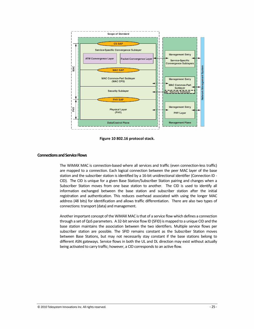
Security Sublayer as shown in Figure 10. Of the three, we will expand on the Convergence
(classification) and Common Parts Sublayers (scheduling) as they have most impact on ensuring
QoS over the WiMAX network.
© 2010 Telesystem Innovations Inc. All rights reserved. - 25 -
Figure 10 802.16 protocol stack.
Connections and Service Flows
The WiMAX MAC is connection-based where all services and traffic (even connection-less traffic)
are mapped to a connection. Each logical connection between the peer MAC layer of the base
station and the subscriber station is identified by a 16-bit unidirectional identifier (Connection ID -
CID). The CID is unique for a given Base Station/Subscriber Station pairing and changes when a
Subscriber Station moves from one base station to another. The CID is used to identify all
information exchanged between the base station and subscriber station after the initial
registration and authentication. This reduces overhead associated with using the longer MAC
address (48 bits) for identification and allows traffic differentiation. There are also two types of
connections: transport (data) and management.
Another important concept of the WiMAX MAC is that of a service flow which defines a connection
through a set of QoS parameters. A 32-bit service flow ID (SFID) is mapped to a unique CID and the
base station maintains the association between the two identifiers. Multiple service flows per
subscriber station are possible. The SFID remains constant as the Subscriber Station moves
between Base Stations, but may not necessarily stay constant if the base stations belong to
different ASN gateways. Service flows in both the UL and DL direction may exist without actually
being activated to carry traffic; however, a CID corresponds to an active flow.
© 2010 Telesystem Innovations Inc. All rights reserved. - 26 -
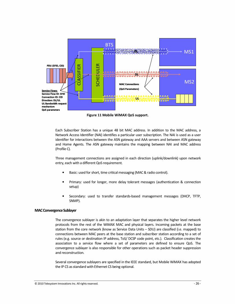
Figure 11 Mobile WiMAX QoS support.
Each Subscriber Station has a unique 48 bit MAC address. In addition to the MAC address, a
Network Access Identifier (NAI) identifies a particular user subscription. The NAI is used as a user
identifier for interactions between the ASN gateway and AAA servers and between ASN gateway
and Home Agents. The ASN gateway maintains the mapping between NAI and MAC address
(Profile C).
Three management connections are assigned in each direction (uplink/downlink) upon network
entry, each with a different QoS requirement.
• Basic: used for short, time critical messaging (MAC & radio control).
• Primary: used for longer, more delay tolerant messages (authentication & connection
setup)
• Secondary: used to transfer standards-based management messages (DHCP, TFTP,
SNMP).
MAC Convergence Sublayer
The convergence sublayer is akin to an adaptation layer that separates the higher level network
protocols from the rest of the WiMAX MAC and physical layers. Incoming packets at the base
station from the core network (know as Service Data Units – SDU) are classified (i.e. mapped) to
connections between MAC peers at the base station and subscriber station according to a set of
rules (e.g. source or destination IP address, ToS/ DCSP code point, etc.). Classification creates the
association to a service flow where a set of parameters are defined to ensure QoS. The
convergence sublayer is also responsible for other operations such as packet header suppression
and reconstruction.
Several convergence sublayers are specified in the IEEE standard, but Mobile WiMAX has adopted
the IP CS as standard with Ethernet CS being optional.
MS1
MS2CLA
SS
IFIE
R
Service Flows:
Service Flow ID: SFID
Connection ID: CID
Direction: DL/UL
UL Bandwidth request
mechanism
QoS parameters
SC
HE
DU
LER
MAC Connections
(QoS Parameters)
BTS
PDU (SFID, CID)
DL
DL
UL
MS1
MS2CLA
SS
IFIE
R
Service Flows:
Service Flow ID: SFID
Connection ID: CID
Direction: DL/UL
UL Bandwidth request
mechanism
QoS parameters
SC
HE
DU
LER
MAC Connections
(QoS Parameters)
BTS
PDU (SFID, CID)
DL
DL
UL
© 2010 Telesystem Innovations Inc. All rights reserved. - 27 -
MAC Common Parts Sublayer
The classified SDUs arrive at the MAC CPS where they are assembled into Packet Data Units (PDU)
which is the basic payload unit of the WiMAX MAC. Several SDUs may be packed into a single PDU
or alternatively, a single SDU is fragmented into several PDUs. The MAC CPS at the receiver does
the opposite operation to extract the SDUs which are delivered to the higher layers.
The MAC PDUs are then scheduled for transmission over the air interface which is done
sequentially in time. The scheduler is responsible for determining the priority of PDU transmission
and for allocating bandwidth to different communication streams between the base station and
the subscribers it serves. It also instructs the subscriber stations of their allocated transmission
time and bandwidth. The function of the scheduler becomes more complex as the quality of the
propagation channel changes continuously resulting in intervals of good and poor transmission
opportunities to each subscriber.
There are two methods to allocate bandwidth to the subscriber station. The first is Grant Per
Connection (GPC) where, as the name implies, bandwidth is granted by the base station to the SS
on a connection by connection basis explicitly. The subscriber station transmits in the order
specified by the base station. The second is Grant Per Subscriber Station where granted bandwidth
by the base station is aggregated into a single grant to the subscriber station to accommodate all
the connections at the SS. The Scheduler in the SS then allocates the granted bandwidth to the
different connections. This allows more flexibility in the system since the SS has the ability to
change bandwidth allocation between connections to account for changes in the QoS situation
since the last bandwidth request was made. (Example: if the QoS situation at the SS has changed
since the last request, the SS has the option of sending the higher QoS data along with a request to
replace this bandwidth stolen from a lower QoS connection. The SS could also use some of the
bandwidth to react more quickly to changing environmental conditions.)
GPC is a simpler technique to grant bandwidth but is less efficient and scalable than GPSS
(particularly where there is more than one connection per SS). GPC leads to multiple entries in the
UL-MAP message creating higher overhead whenever a subscriber with multiple connections is
polled or granted transmission opportunities. GPSS is scalable to a higher number of subscriber
stations and connections. GPSS allows the subscriber station to react quicker to the status of the
physical layer and the requirements of the connection and applications running on the SS. This
enhances system performance.
WiMAX uses a self correcting protocol as opposed to an acknowledged protocol which increases
efficiency and decreases delay. In case a bandwidth requested by a SS is not granted, the SS will
initiate another request after a time-out period. The bandwidth request is incremental where the
SS asks for more bandwidth for a connection.
The subscriber uses the Range Request (RNG-REQ) message to request a change in the downlink
burst profile. Another message is the Downlink Burst Profile Change Request (DBPC-REQ). The
Downlink Burst Profile Change Response (DBPC-RSP) message confirms or denies the change.
Because the quality of the propagation channel changes continuously, messages between the base
station and subscriber station may be lost. This requires different order of burst profile change
when transitioning from to a more robust profile than when transitioning to a less robust one.

© 2010 Telesystem Innovations Inc. All rights reserved. - 28 -
Scheduling Services
A scheduling service is used to determine the mechanism to allocate transmission opportunity for
MAC PDUs. Mobile WiMAX defines five scheduling services as summarized in Table 15:
1. Unsolicited Grant Service (UGS) offers fixed-size grants on a real-time periodic basis and does
not need the subscriber station to explicitly request bandwidth. This eliminates the overhead and
latency associated with bandwidth request. UGS is appropriate for real-time service flows that
generate fixed-size data packets on a periodic basis, such as T1/E1.
2. Real-time Polling Services (rtPS) is designed to support real-time services that generate variable-
size data packets on a periodic basis, such as MPEG (Motion Pictures Experts Group) video. In this
service class, the base station provides unicast polling opportunities for the subscriber station to
request bandwidth. The unicast polling opportunities are frequent enough to ensure that latency
requirements of real-time services are met. This service requires more request overhead than UGS
does but is more efficient for service that generates variable-size data packets or has a duty cycle
less than 100 percent.
Table 15 Scheduling services in Mobile WiMAX.
QoS Class Applications Mandatory QoS Parameters
UGS
Unsolicited Grant
Service
E1/T1, VoIP (without silence
suppression)
• Maximum Sustained Traffic Rate (=
minimum reserved traffic rate)
• Maximum Latency Tolerance
• Jitter Tolerance
rtPS
Real-Time Packet
Service
Streaming Audio or Video (e.g.
MPEG)
• Minimum Reserved Traffic Rate
• Maximum Sustained Traffic Rate
• Maximum Latency Tolerance
• Traffic Priority
ertPS
Extended Real-
Time Packet
Service
Voice with Activity Detection
(VoIP)
• Minimum Reserved Traffic Rate
• Maximum Sustained Traffic Rate
• Maximum Latency Tolerance
• Jitter Tolerance
• Traffic Priority
nrtPS
Non-Real-Time
Packet Service
File Transfer Protocol (FTP)
• Minimum Reserved Traffic Rate
• Maximum Sustained Traffic Rate
• Traffic Priority
BE
Best-Effort
Service
Data Transfer, Web Browsing,
etc.
• Maximum Sustained Traffic Rate
• Traffic Priority
3. Non-real-time Polling Services (nrtPS) is very similar to rtPS except that the subscriber station
can also use contention-based polling in the uplink to request bandwidth. In nrtPS, it is allowable
to have unicast polling opportunities, but the average duration between two such opportunities is
in the order of few seconds, which is large compared to rtPS. All the subscriber stations belonging
to the group can also request resources during the contention-based polling opportunity, which
can often result in collisions and additional attempts.
© 2010 Telesystem Innovations Inc. All rights reserved. - 29 -
4. Extended Real-time Polling Service (ertPS) is a new scheduling service introduced with the IEEE
802.16e standard and adopted in the Mobile WiMAX system profile. In this class, periodic UL
allocations provided for a particular subscriber station can be used either for data transmission or
for requesting additional bandwidth. This feature allows ertPS to accommodate data services
whose bandwidth requirements change with time such as VoIP with activity detection (silence
suppression).
5. Best-effort Service (BE) provides very little QoS support and is applicable only for services that
do not have strict QoS requirements. Data is sent whenever resources are available and not
required by any other scheduling-service classes. The subscriber station uses only the contention-
based polling opportunity to request bandwidth.
End-to-End Quality of Service
End-to-end Quality of Service is available with WiMAX access network using the IEEE and IETF
standards. The WiMAX network follows the IEEE 802.16 standard that specifies five scheduling
service classes which facilitate priority access to the wireless medium. These scheduling classes are
mapped into the IETF’s Diffserv (Differentiated Services) Expedited Forwarding (EF) and Assured
Forwarding (AF) classes.
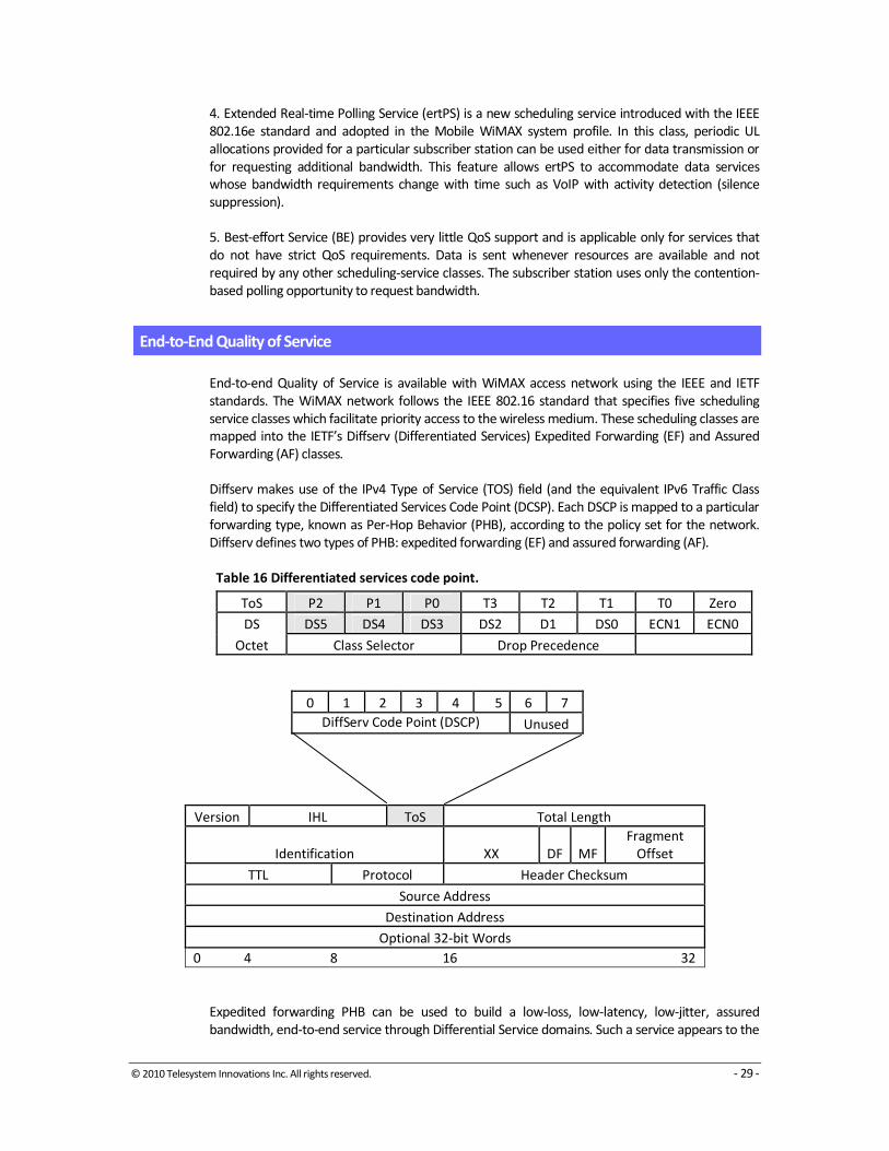
Diffserv makes use of the IPv4 Type of Service (TOS) field (and the equivalent IPv6 Traffic Class
field) to specify the Differentiated Services Code Point (DCSP). Each DSCP is mapped to a particular
forwarding type, known as Per-Hop Behavior (PHB), according to the policy set for the network.
Diffserv defines two types of PHB: expedited forwarding (EF) and assured forwarding (AF).
Table 16 Differentiated services code point.
ToS P2 P1 P0 T3 T2 T1 T0 Zero
DS DS5 DS4 DS3 DS2 D1 DS0 ECN1 ECN0
Octet Class Selector Drop Precedence
0 1 2 3 4 5 6 7
DiffServ Code Point (DSCP) Unused
Version IHL ToS Total Length
Identification XX DF MF
Fragment
Offset
TTL Protocol Header Checksum
Source Address
Destination Address
Optional 32-bit Words
0 4 8 16 32
Expedited forwarding PHB can be used to build a low-loss, low-latency, low-jitter, assured
bandwidth, end-to-end service through Differential Service domains. Such a service appears to the

© 2010 Telesystem Innovations Inc. All rights reserved. - 30 -
endpoints like a point-to-point connection or a “virtual circuit”. EF is provided by ensuring that
queuing delays at each transit node are removed. This is done by assigning to a given traffic stream
a minimum departure rate from each transit node that is greater than the pre-agreed maximum
arrival rate.
Assured forwarding PHB is a service in which packets from a given source are forwarded with a
given probability, provided that the traffic from that source does not exceed some pre-agreed
maximum. There are four AF classes. Each class is allocated a certain amount of forwarding
resources (buffer space and bandwidth) in each transit node. Within each AF class, IP packets are
marked with one of three possible drop precedence values. In case of congestion, the drop
precedence of a packet determines the relative importance of the packet within the class. A
congested transit node tries to protect packets with a lower drop precedence value from being lost
by preferably discarding packets with a higher drop precedence value.
IP QoS flows are simply mapped to an appropriate DiffServ per-hop behavior (PHB) over the flash-
OFDMA air link.

© 2010 Telesystem Innovations Inc. All rights reserved. - 31 -
6 WiMAX Usage Scenarios and Applications
WiMAX Usage Scenarios
WiMAX is suited to support a large number of usage scenarios based on its technical features and
commercial cost points. These scenarios and their key requirements are shown in Table 17.
Table 17 WiMAX Usage Scenarios.
Usage Scenario
Fle
xib
le A
rch
ite
ctu
re
Hig
h S
ecu
rity
WiM
AX
Qo
S
Qu
ick
De
plo
ym
en
t
Mu
lti-
Lev
el
Se
rvic
e
Inte
rop
era
bil
ity
Po
rta
bil
ity
Mo
bil
ity
Co
st-E
ffe
ctiv
e
Wid
er
Co
ve
rag
e
NLO
S
Hig
h C
ap
aci
ty
Banking Networks � � � � �
Education Networks � � � �
Public Safety � � � � � � �
Offshore Communications � � � � � �
Campus Connectivity � � � �
Temporary Construction � � � �
Theme Parks � � � � �
WSP Access Network � � � � � � �
Rural Connectivity � � � �
Military Applications � � � � �
Private Networks
Private networks are used exclusively by a single organization, institution or business to offer
dedicated communication links for voice, data and video applications. Private networks generally
need to be quick and easy to install.
Banking Networks
Large banks can connect branches and ATM (Automated Teller Machine) sites to their regional
office through a private WiMAX network carrying voice, data and video traffic. Banks typically
require high security and bandwidth to handle the traffic load. WiMAX data encryption offers
over-the-air link security, however, banks will most likely also need end-to-end security, such as
that provided by SSL or IPSec, to protect against interception and manipulation of sensitive
banking data.
WiMAX networks also offer a high degree of scalability, so that low-data-rate traffic between the
regional office and ATM machines can co-exist with the high levels of traffic needed to support
branch-to-regional office communications. This is made possible by the WiMAX QoS, which is used
to prioritize voice (telephony among branches), data (financial transactions, email, Internet, and
intranet) and video (surveillance, CCTV) traffic.

© 2010 Telesystem Innovations Inc. All rights reserved. - 32 -
Education Networks
School boards can use WiMAX networks to connect schools and school board offices within a
district. Some of the key requirements for a school system are NLOS, high bandwidth (>15 Mbps),
Point-to-Point and Point-to-Multipoint capability, and a large coverage footprint. WiMAX-based
education networks, using QoS, can deliver the full range of communication requirements,
including telephony voice, operating data (such as student records), email, Internet and intranet
access (data), and distance education (video) between the school board office and all of the
schools in the school district, and between the schools themselves.
The WiMAX solution provides broad coverage, making it very cost-effective, particularly for rural
schools, which may have little or no communications infrastructure, and which are widely
dispersed.
Public Safety
Government public safety agencies, such as police, fire, and search and rescue, can use WiMAX
networks to support response to medical and other emergency situations. In addition to providing
two-way voice communications between the dispatch center and on-site emergency response
teams, the network relays video images and data from the site of the accident or disaster to the
control center. This data can be relayed to expert teams of medical or emergency staff, who can
analyze the situation in real-time, as if they were on site.
WiMAX QoS allows the network to handle these diverse types of traffic. WiMAX solutions are
highly deployable, so the initial response team can set up a temporary wireless network at the site
of the accident, event, or natural disaster, in a matter of minutes. They can also relay traffic from
this network back to a control or dispatch center, over an existing WiMAX network.
As well, there may be a requirement for mobility, such as, for example, a policeman having to
access a database from a moving vehicle, or a fireman having to download information about the
best route to a fire scene or the architecture of the building on fire. A video camera in the
ambulance can offer advance information about the condition of a patient, before the ambulance
reaches the hospital.
Offshore Communications
Oil and gas producers can use WiMAX equipment to provide communication links from and-based
facilities to oilrigs and platforms, to support remote operations, security, and basic
communications. Remote operations include remote troubleshooting of complex equipment
problems, site monitoring, and database access. For example, video clips of malfunctioning
components or subassemblies can be transmitted to a land-based team of experts for analysis.
Security includes alarm monitoring and video surveillance. Basic communications includes voice
telephony, email, Internet access, and video conferencing.
Campus Connectivity
Government agencies, large enterprises, industrial campuses, transportation hubs, universities,
and colleges, can use WiMAX networks to connect multiple locations, sites and offices within their
campus. Campus systems require high data capacity, low latency, a large coverage footprint, and
high security. Like other usage scenarios, campus networks carry a mix of voice, data, and video,
which the WiMAX QoS helps prioritize and optimize.

© 2010 Telesystem Innovations Inc. All rights reserved. - 33 -
Temporary Construction Communications
Construction companies can use WiMAX networks to establish communication links between the
company head office, construction sites, offices of other project participants, such as architectural
and engineering firms, and storage facilities. The fast deployment of WiMAX networks is also
important in this scenario, since it allows for quick provision of communications to the
construction site, including voice (telephony) and data (emails, engineering drawings, and Internet
access). Surveillance video can also be carried over the network, to support monitoring of the site
or areas of the site that are otherwise difficult to access. A local Hotspot can also be set up at the
construction site, allowing personnel at the site to communicate and exchange data and schedule
information.
Like the other usage scenarios, the WiMAX built-in QoS will prioritize network traffic and optimize
the communications channel. Construction sites include, but are not limited to, office buildings,
residential land development, and oil and gas facilities.
Theme Parks
Theme park operators can use WiMAX to deliver a broad range of communication services for
their amusement parks, expositions, hospitality and operation centers, and buses and service
vehicles. The above network can support a wide range of communications traffic, including two-
way dispatch from a control center, video surveillance throughout the park, reservation data,
inventory database access and update, site status monitoring, video on demand, and voice
telephony. Some of the key requirements for a system like this are support for fixed and mobile
operations, high security, scalable architecture and low latency.
WiMAX mobility capability will support two-way voice and data communications to the theme
park’s tour buses and service vehicles. Real-time video can be broadcast to tour buses, providing
tourist information, promotions, and weather to passengers.
Public Networks
In public network, resources are accessed and shared by different users, including both businesses
and private individuals. Public networks generally require a cost-effective means of providing
ubiquitous coverage, since the location of the users is neither predictable nor fixed. The main
applications of public networks are voice and data communication, although video communication
is becoming increasingly popular. Security is a critical requirement, since many users share the
network. A few usage scenarios involving public networks are shown below.
Wireless Service Provider Access Network
Wireless Service Providers (WSPs) use WiMAX networks to provide connectivity to both residential
(voice, data and video) and business (primarily voice and Internet) customers. The WSP could be a
CLEC (Competitive Local Exchange Carriers) that is starting its business with little or no installed
infrastructure. Since WiMAX is easy to deploy, the CLEC can quickly install its network and be in
position to compete with the ILEC (Incumbent Local Exchange Carrier). The WiMAX built-in QoS
mechanism is highly suited for the mix of traffic carried by the CLEC. The QoS MAC also offers
multi-level service to address the variety of customer service needs. A common network platform,
offering voice, data and video, is highly attractive to end customers, because it presents a one-stop
shop and a single monthly bill. Support for multiple service types allows for different revenue
streams, yet it reduces customer acquisition cost, and increases ARPU (Average Revenue per
User). The WSP needs only one billing system and one customer database.
© 2010 Telesystem Innovations Inc. All rights reserved. - 34 -
Rural Connectivity
Service providers use WiMAX networks to deliver service to underserved markets in rural areas
and the suburban outskirts of cities. The delivery of rural connectivity is critical in many developing
countries and underserved areas of developed countries, where little or no infrastructure is
available.
Rural connectivity delivers much-needed voice telephony and Internet service. Since the WiMAX
solution provides extended coverage, it is a much more cost-effective solution than wired
technology in areas with lower population densities.
Application Requirements
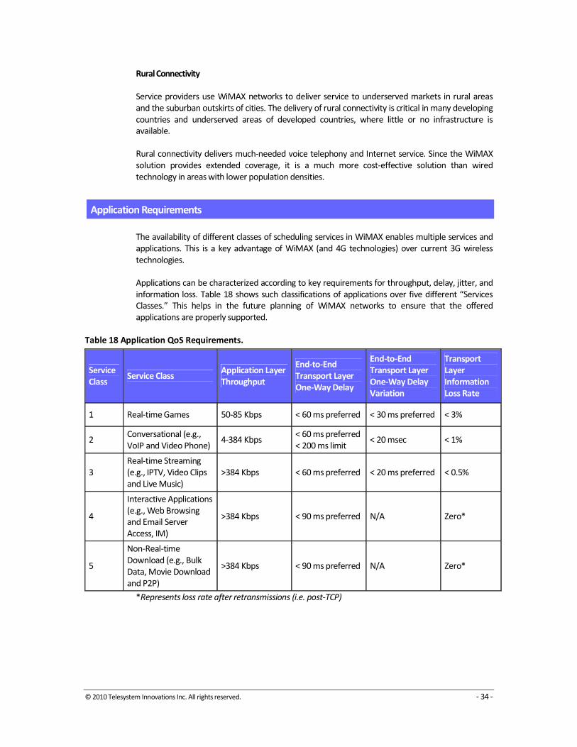
The availability of different classes of scheduling services in WiMAX enables multiple services and
applications. This is a key advantage of WiMAX (and 4G technologies) over current 3G wireless
technologies.
Applications can be characterized according to key requirements for throughput, delay, jitter, and
information loss. Table 18 shows such classifications of applications over five different “Services
Classes.” This helps in the future planning of WiMAX networks to ensure that the offered
applications are properly supported.
Table 18 Application QoS Requirements.
Service
Class Service Class
Application Layer
Throughput
End-to-End
Transport Layer
One-Way Delay
End-to-End
Transport Layer
One-Way Delay
Variation
Transport
Layer
Information
Loss Rate
1 Real-time Games 50-85 Kbps < 60 ms preferred < 30 ms preferred < 3%
2 Conversational (e.g.,
VoIP and Video Phone) 4-384 Kbps
< 60 ms preferred
< 200 ms limit < 20 msec < 1%
3
Real-time Streaming
(e.g., IPTV, Video Clips
and Live Music)
>384 Kbps < 60 ms preferred < 20 ms preferred < 0.5%
4
Interactive Applications
(e.g., Web Browsing
and Email Server
Access, IM)
>384 Kbps < 90 ms preferred N/A Zero*
5
Non-Real-time
Download (e.g., Bulk
Data, Movie Download
and P2P)
>384 Kbps < 90 ms preferred N/A Zero*
*Represents loss rate after retransmissions (i.e. post-TCP)

© 2010 Telesystem Innovations Inc. All rights reserved. - 35 -
About Telesystem Innovations Inc. Telesystem Innovations is a management and technical consulting firm providing expert strategic advice on 4G
wireless technologies (LTE, WiMAX) including technology evaluation; spectrum pricing; business plan and
financial modeling; and product and technology roadmap. Our clients include major network operators,
original equipment manufacturers/system vendors and venture capital firms.
Corporate Headquarters
18 Byer Drive
Markham, ON L3P 6V9
Canada
+1.416.969.9570
Inquiries
Frank Rayal, CTO
+1.416.294.7211
For more information please visit
www.tsiwireless.com