fundamentals of structural design part of steel structurespeople.fsv.cvut.cz/~sokol/fstd/copy of...
TRANSCRIPT

1
1
Fundamentals of Structural DesignPart of Steel Structures
Civil Engineering for Bachelors133FSTD
Teacher: Zdeněk SokolOffice number: B619
2
Syllabus of lectures
1. Introduction, history of steel structures, the applications and some representative structures, production of steel
2. Steel products, material properties and testing, steel grades3. Manufacturing of steel structures, welding, mechanical fasteners4. Safety of structures, limit state design, codes and specifications for the
design5. Tension, compression, buckling6. Classification of cross sections, bending, shear, serviceability limit states7. Buckling of webs, lateral-torsional stability, torsion, combination of
internal forces 8. Fatigue9. Design of bolted and welded connections10. Steel-concrete composite structures11. Fire and corrosion resistance, protection of steel structures, life cycle
assessment

2
3
Scope of the lecture
Stability of websWeb stiffeners
Shear loads
Local concentrated loads
Torsion
Combined actions
4
Stability (buckling) of webs
Webs are loaded
By compressionThis is introduced as effective sections properties of Class 4 cross-sections, but not explained in details in FSTD
By shear
By concentrated local load

3
5
Beam web stiffeners
Beam web stiffeners
Stiffeners of composite box girder for steel-concrete composite bridge
I section beam with stiffeners welded by fillet welds
Beam web stiffeners
6
Beam web stiffeners
Typical shapes of beam web stiffeners

4
7
Scope of the lecture
Stability of websWeb stiffeners
Shear loads
Local concentrated loads
Torsion
Combined actions
8
Shear buckling of beam web
Shear buckling of beam web

5
9
Principle of tension field
Tension field in the beam web
Fictive truss with diagonals loaded in tension
Fictive truss is used as model for the beam just before the collapse when the shear is resisted by tensile fields (now replaced by diagonals of the truss) and the stiffeners of the beam web are loaded in compression (now replaced by vertical elements of the truss)
10
Web loaded by shear
Buckling of the web is in principle similar to buckling of elements in compression
Two cases need to be considered: Perfect plate – critical stress cr can be obtained
Real plate – imperfections play important role and should be considered
However, behaviour of web after buckling occurs is significantly different
The effect of these parameters needs to be considered - Imperfections lead to web buckling and reduce the shear resistance
+ Post-critical reserve caused by tensile fields which reduce the effect of imperfections (actually reduce the amplitude of bow-shaped deformation of the web)
The tensile fields reduce the effect of buckling and increase the resistance of the web, therefore higher resistance can be observed than resistance based on critical stress cr
Critical stress of the web cr
Real stress in the web
Real and critical stress of the beam web

6
12
Shear buckling of webs – when to check
It is necessary to consider web buckling in shear and therefore to reduce the shear resistance in the following cases: web without stiffeners
web with transverse stiffeners only
for more complicated stiffeners pattern, the method is given in Eurocode
kt
d
w
30
69wt
d
Beam web stiffened by longitudinaland transverse stiffeners
13
The shear resistance with respect to web buckling is given by
where ba is function of the web slenderness λw
The strength ba is equal to
Shear resistance of slender web
1M
bawRd,ba
tdV
kt,
tdf
w
baw
cr
yw
437
3
ww
yba
wwy
ba
wy
ba
,,f
,,,,f
,f
2190
3
218080425013
803
…………………………when
……………………when
…when

7
14
Scope of the lecture
Stability of websWeb stiffeners
Shear loads
Local concentrated loads
Torsion
Combined actions
15
Local concentrated loads (transverse forces)
Normally, web stiffener is designed at locations where local concentrated load is presented (column, connected beam, etc.)
In some situations, the load can not transferred into the stiffener (wheel of bridge crane)
The column delivers a concentrated load to the beam and a bearing stiffener is used on the web

8
16
Local concentrated loads (transverse forces)
Web crushing at a support point of thin-walled cold formed C section,
no stiffeners can be used here
17
Distribution length ss
Local concentrated loads
Resistance check to concentrated loads include: Buckling of the web below the concentrated load Combination of stresses in web at the vicinity of load
where x, z are axial stresses at perpendicular directions (sign included)x is the stress from bending momentz is the stress from concentrated load distributed to length ss
is the shear stress
1
222 3M
yzxzx
f
9
18
Scope of the lecture
Stability of websWeb stiffeners
Shear loads
Local concentrated loads
Torsion
Combined actions
19
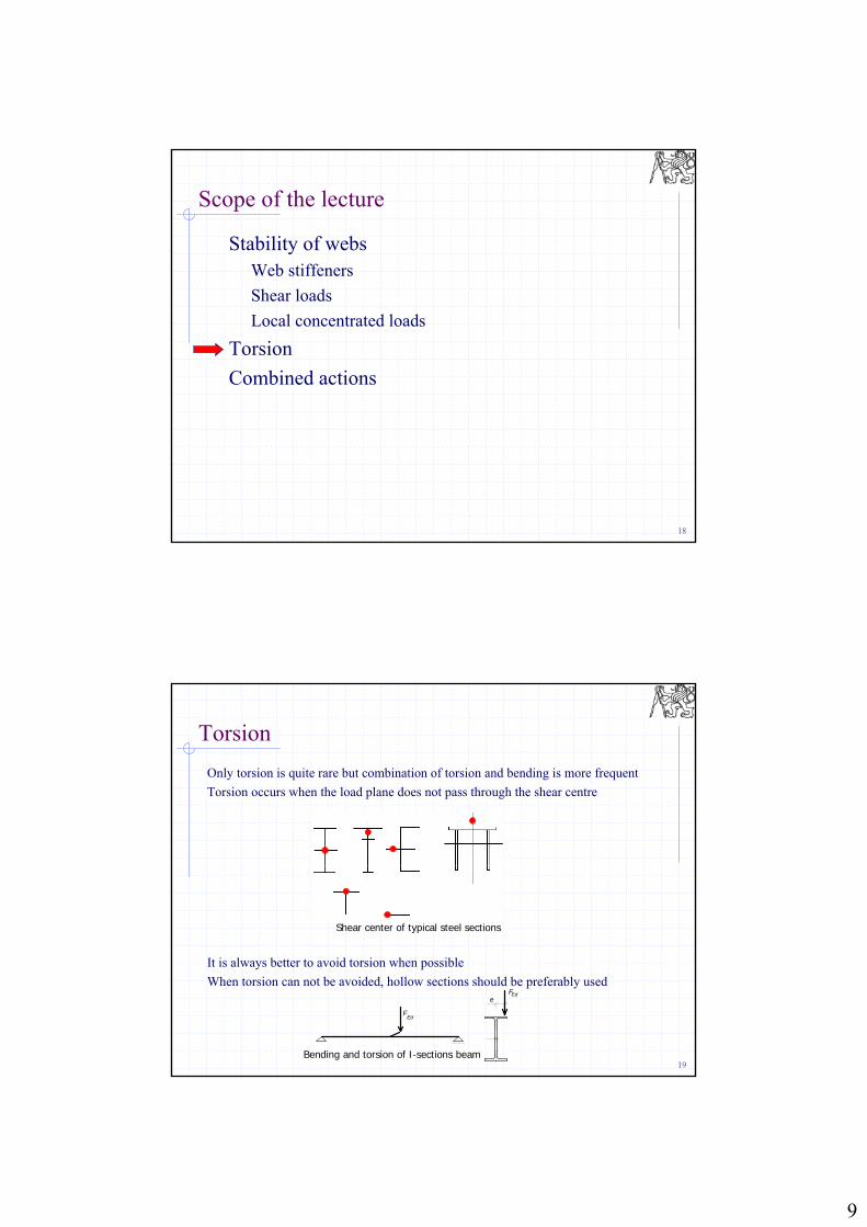
Torsion
Only torsion is quite rare but combination of torsion and bending is more frequent
Torsion occurs when the load plane does not pass through the shear centre
It is always better to avoid torsion when possible
When torsion can not be avoided, hollow sections should be preferably usede
FEd
FEd
Shear center of typical steel sections
Bending and torsion of I-sections beam

10
20
Torsion – cross-sections
Open cross-sectionsThey have low torsional stiffness, therefore are not suitable for high torsion momentsSignificant stresses (both shear and axial) are created which must be considered for the resistance checkSt.Venant + warping torsion occurs, resulting in shear t + w and axial stress w appear (Mx = Tt + Tw)Exception: when all parts intersect at single point (L, T sections), only St. Venant torsion and only t occurs (Mx = Tt)
Hollow cross-sectionsThey have high torsional stiffness and are suitable to transfer torsionSt.Venant occurs, only shear stress t appears
21
Open cross-sections, St. Venant torsion
Shear stress
where
Tt torsion moment
It torsion constant
t thickness of the element
The torsion constant is
bi width
ti thickness of that part of the element
cross-section shape coefficient ( 1)
tI
T
t
ti,t
3
3
1iit tbI
11
22
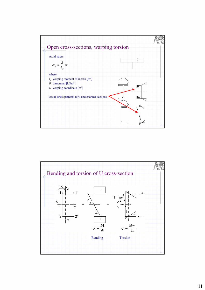
Open cross-sections, warping torsion
Axial stress
where
Iw warping moment of inertia [m6]
B bimoment [kNm2]
w warping coordinate [m2]
Axial stress patterns for I and channel sections
wI
B
ww
23
Bending and torsion of U cross-section
Bending Torsion

12
24
Bi-axial bending and torsion of I cross-section
Bending My Bending Mz Torsion
25
Hollow cross-sections
Only shear stress occurs
where
Tt torsion moment
ti thickness of the element
As area enclosed by the cross-section
i
t
ii,t t
T
t
Q
1
sA2 As
13
27
Scope of the lecture
Stability of websShear loads
Local concentrated loads
Torsion
Combined actions
28
Combined actions
Bi-axial bending
Bending + tension
Bending + compression

14
29
Bi-axial bending - review
1
Rd,z,c
Ed,z
Rd,y,c
Ed,y
M
M
M
M
My,Ed , Mz,Ed bending moments acting about y and z axes
Mc,y,Rd , Mc,z,Rd bending moment resistances
It is possible to take into account
= = 1
(conservative approach)
Accurate method for various cross section shapes (i.e. the values of and ) is given in Eurocode
Interaction diagram for bi-axial bending
c,z,RdM
c,y,RdM
zM
yM
30
Bending + tension
Example: Tension chord of truss with inter-nodal load
Class 1,2 sections – plastic behaviour can be considered
Class 3 sections – elastic behaviour is be considered, the stresses from bending and axial force are combined
0M
y
y,el
EdEd,t f
W
M
A
N
1
00
M
yy,el
Ed
M
y
Ed,t
fW
Mf
A
N
1
2
Rd,pl
Ed,t
Rd,pl
Ed
N
N
M
M

15
31
Bending + tension
Bi-axial bending + tension
1Rd,z,pl
Ed,z
Rd,y,pl
Ed,y
Rd,pl
Ed,t
M
M
M
M
N
N
32
Bending + compression
Typical cases:
columns with lateral load
columns with eccentric load
frames
compression chord of truss with inter-nodal load

16
33
Bending + compression
34
Bending + compression

17
35
Bending + compression
Second-order effect should be included
Derivation – as for buckling resistance of elements loaded in compression initial curvature
primary moments MEd
secondary moments NEde
N
M
L NeMe
N
M
NM
e0
NM Momenty:
36
Bending + compression
For element pinned at both ends, the maximum bending moment on the element (including the second order effect) is equal to:
when NEd Ncr, the moment max M ∞
Maximum stress in the element is
or
cr
EdEdEdEd
NN
MeNMMmax1
1
1
1
ycr
Ed
Ed
y
Ed
fWN
N
M
fA
N
yEd
max fW
Mmax
A
N
factor kyy introducing the second order effect

18
37
Effect of moment pattern
Effects of N+M add
kyy > 1
Effects of N+M eliminate
kyy < 1
38
Check according to EN 1993-1-1
2 conditions are considered:1. In plane buckling
2. Out of plane buckling
Both formulas have to be fulfilled
W (and My,Rk) should be taken according to class of the cross-section
1
11
M
y,RkLT
y,Edy,Edyy
M
Rky
Ed
γ
Mχ
ΔMMk
γ
NχN
1
11
M
y,RkLT
y,Edy,Edzy
M
Rkz
Ed
γ
Mχ
ΔMMk
γ
NχN
19
39
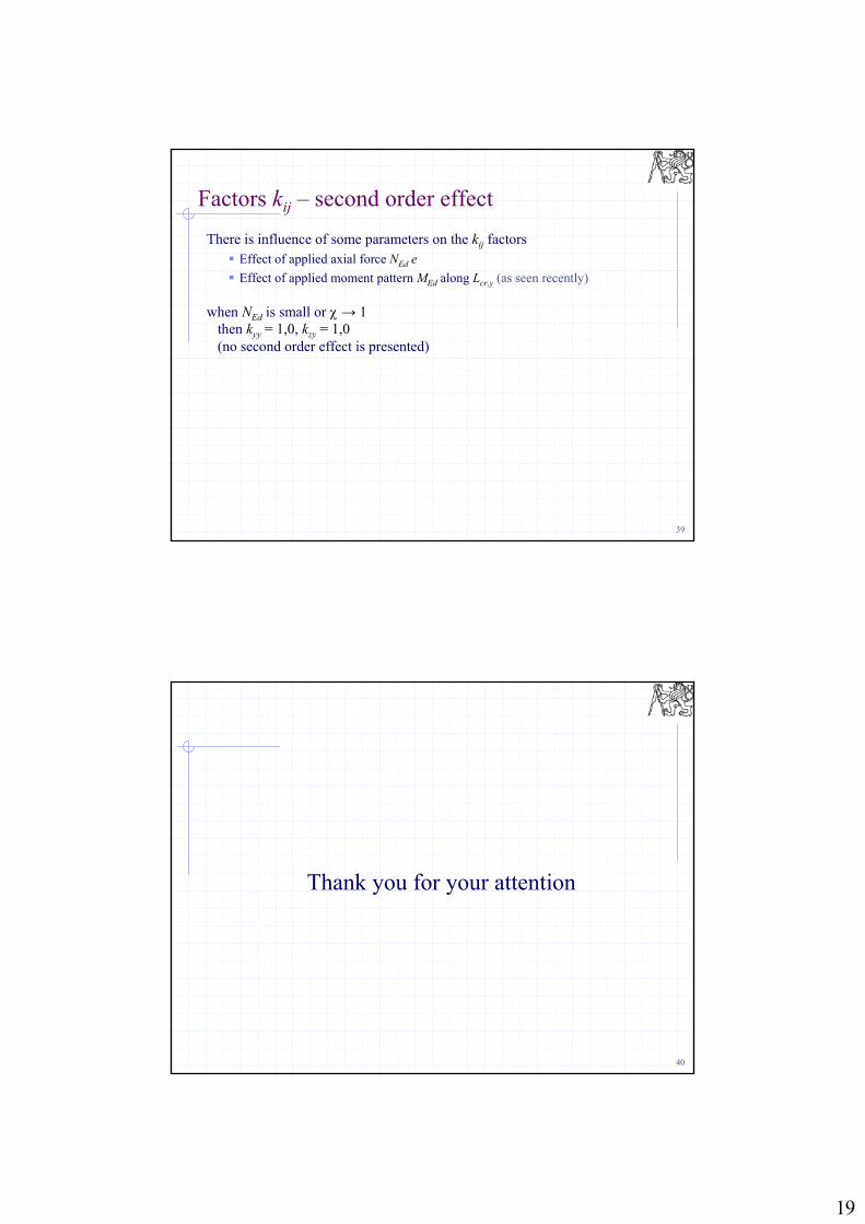
Factors kij – second order effect
There is influence of some parameters on the kij factors Effect of applied axial force NEd e
Effect of applied moment pattern MEd along Lcr,y (as seen recently)
when NEd is small or → 1then kyy = 1,0, kzy = 1,0(no second order effect is presented)
40
Thank you for your attention