fundamentals of slot coating process - · pdf filefundamentals of slot coating process prof....
TRANSCRIPT

Fundamentals of Slot Coating Process
Prof. Marcio Carvalho
http://carvalho.usuarios.rdc.puc-rio.br/

Coating process is the main manufacturing step
for many different (old) products…
Adhesive tapes Magnetic tapes and
disks Paper
Needs:
Higher yields and faster production speed;
Process improvement and optimization.
Introduction

Flexible and transparent
electronics
Thin / flexible displays:
Plasma, LCD, OLED, …
Coating process is the main manufacturing step
for many different (new) products…
Needs:
Uniformity requirements are extremely tight;
May need 3D features;
Process optimization to minimize film thickness variation.
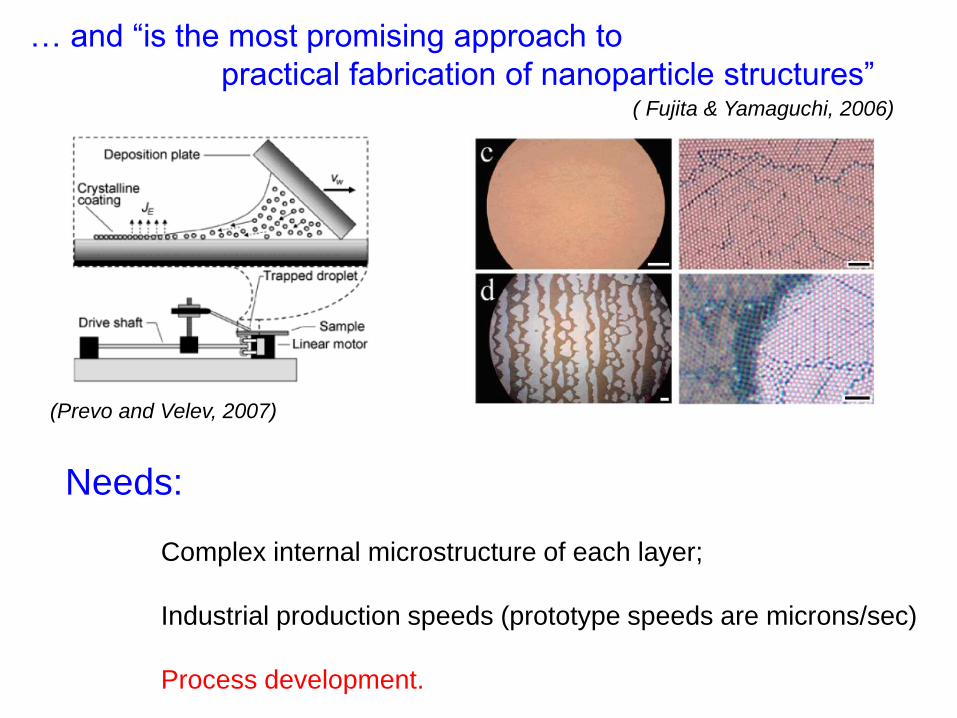
… and “is the most promising approach to
practical fabrication of nanoparticle structures” ( Fujita & Yamaguchi, 2006)
(Prevo and Velev, 2007)
Needs:
Complex internal microstructure of each layer;
Industrial production speeds (prototype speeds are microns/sec)
Process development.
FUNCTIONAL COATINGS AND FILMS
Coatings and films produced by depositing a liquid
layer and subsequently solidifying it are vital
ingredients of many different kind of products.
The interior of many coatings and films has to have
particular microstructure or nanostructure in order
to function as intended, whether optically, photo-
chemically, electronically or mechanically.
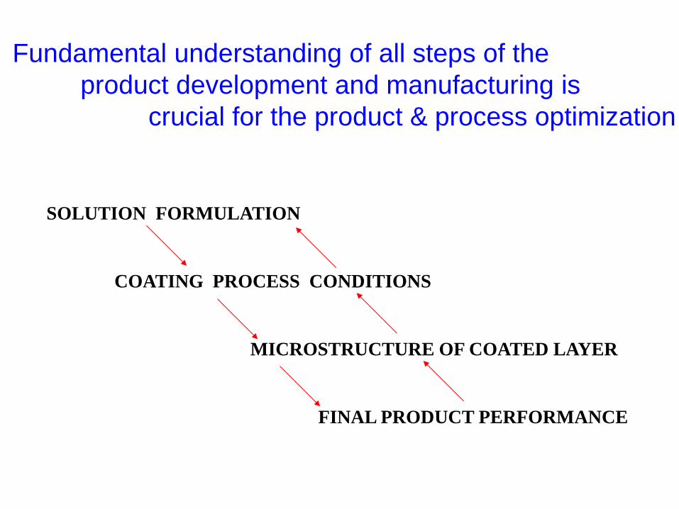
SOLUTION FORMULATION
COATING PROCESS CONDITIONS
MICROSTRUCTURE OF COATED LAYER
FINAL PRODUCT PERFORMANCE
Fundamental understanding of all steps of the
product development and manufacturing is
crucial for the product & process optimization

Unit Operations of a typical coating line
Liquid wets the substrate and forms a thin uniform film;
In most cases, the film should be thin and uniform;
Limitations on how fast this process can be run.

Development of Coating Technology
DEVELOPMENTS WERE RESTRICTED TO EACH INDUSTRY SEGMENT
FIRST PART OF 20TH CENTURY, COATING TECHNOLOGY WAS AN ART
COATING IS A MULTI-DISCIPLINARY SUBJECT
WETTING, SPREADING;
ADHESION;
FLUID MECHANICS AND RHEOLOGY;
CHEMISTRY, INTERFACIAL SCIENCE; …
FROM 1940’S, MATHEMATICAL MODELING AND CAREFUL EXPERIMENTS
(NOT ONLY PILOT TRIALS) STARTED TO BE USED
TO DEVELOP AND IMPROVE COATING PROCESSES
COMPETITIVE PRESSURE DRIVES THE TECHNOLOGY,
IMPORTANT TO ANALYZE THE PHYSICAL MECHANISMS THAT
DETERMINES THE SUCCESS OR FAILURE OF THE PROCESS

Technological Challenges in the Coating Industry
Thinner and more uniform wet coating layer;
Reduction of emission of organic solvents –
more concentrated solutions;
New coating liquid formulations and
more complex product structure;
Discrete and non-continuous coating;
Increase in line speed and yields;
Adapting existing coating lines for new products;

Coating Fundamentals Research
Move from not only Know-how (process developement) to also Know-why (process understanding) Need fundamental understanding of the basics mechanisms involved in all phases of the process: liquid preparation, coating, and solidification.
Theory
Numerics Experiments
Need specially developed experimental and numerical tools to be able to study in detail all the mechanisms involved.

Flow and microstructure development visualization
Slot coating visualization: analysis of bead breakup mechanisms – Romero and Carvalho (2004) Micro structure development
During drying – Cardinal and Francis, AIChE J (2011)
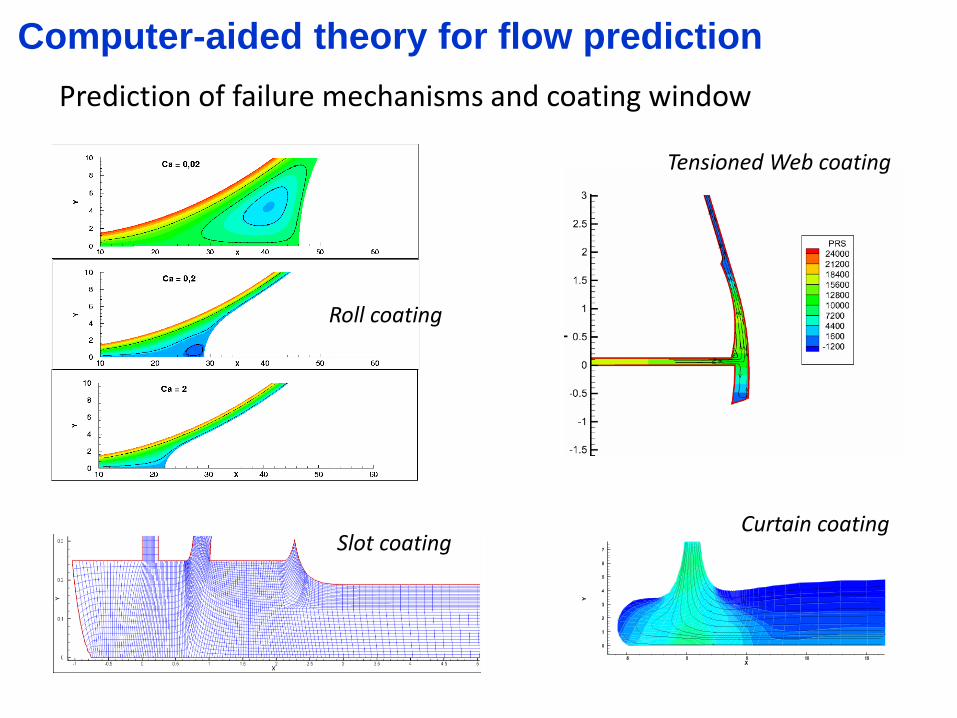
Computer-aided theory for flow prediction
Prediction of failure mechanisms and coating window
Roll coating
Slot coating Curtain coating
Tensioned Web coating

Slot Coating Process – Fundamentals
SLOT COATING IS USED IN THE MANUFACTURING PROCESS
OF MANY DIFFERENT PRODUCTS
PRE-METERED METHOD: THICKNESS IS SET BY FLOW RATE
FLOW UNIFORMITY IN THE COATING BEAD IS STRONGLY AFFECTED
BY OPERATING PARAMETERS
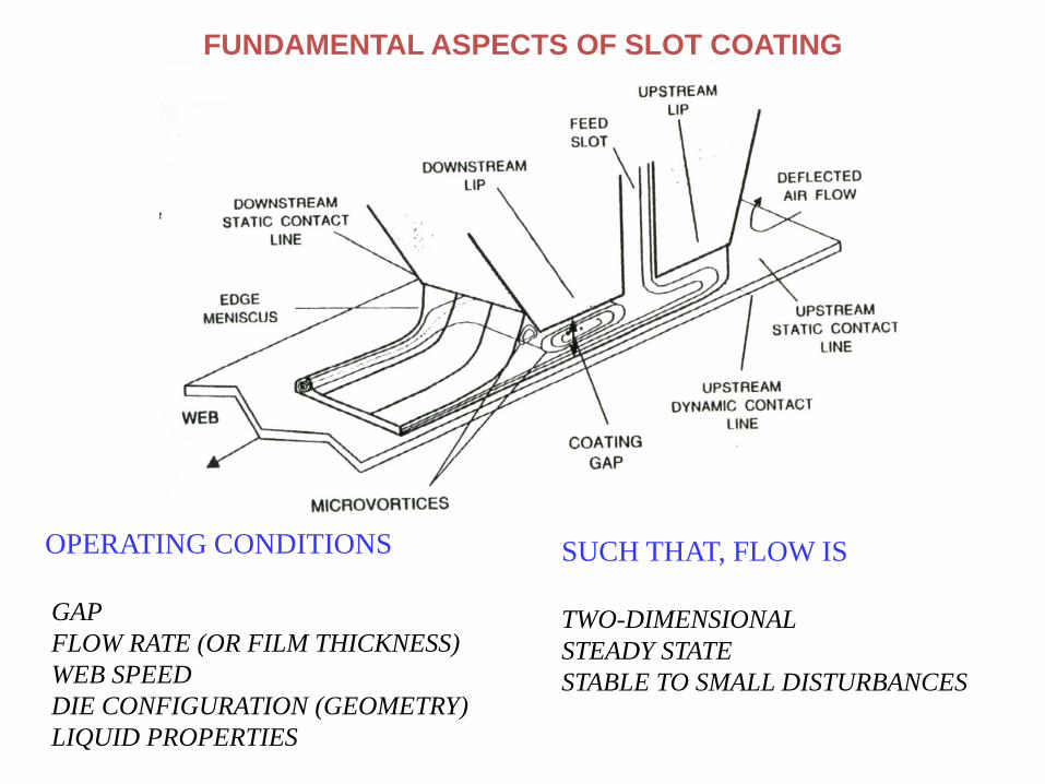
FUNDAMENTAL ASPECTS OF SLOT COATING
OPERATING CONDITIONS
GAP
FLOW RATE (OR FILM THICKNESS)
WEB SPEED
DIE CONFIGURATION (GEOMETRY)
LIQUID PROPERTIES
SUCH THAT, FLOW IS
TWO-DIMENSIONAL
STEADY STATE
STABLE TO SMALL DISTURBANCES
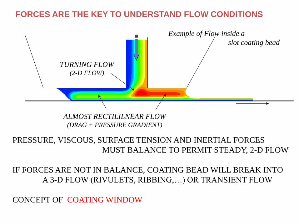
FORCES ARE THE KEY TO UNDERSTAND FLOW CONDITIONS
TURNING FLOW (2-D FLOW)
ALMOST RECTILILNEAR FLOW (DRAG + PRESSURE GRADIENT)
PRESSURE, VISCOUS, SURFACE TENSION AND INERTIAL FORCES
MUST BALANCE TO PERMIT STEADY, 2-D FLOW
IF FORCES ARE NOT IN BALANCE, COATING BEAD WILL BREAK INTO
A 3-D FLOW (RIVULETS, RIBBING,…) OR TRANSIENT FLOW
CONCEPT OF COATING WINDOW
Example of Flow inside a
slot coating bead

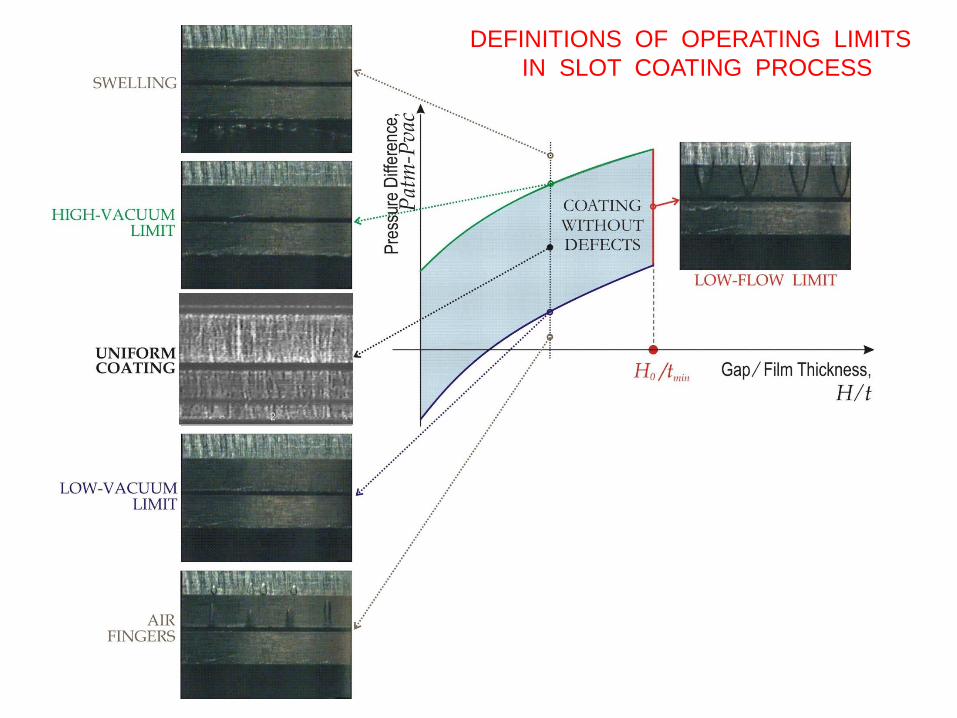
THE COATING WINDOW IS BORDERED BY DEFECTS
UPSTREAM PRESSURE TOO LOW
LIQUID INVADES VACUUM CHAMBER
PREMETERED ACTION IS LOST
NOT ENOUGH VACUUM
UPSTREAM MENISCUS
INVADES COATING BEAD
MINIMUM WET THICKNESS THAT CAN
BE COATED AT
GIVEN SUBSTRATE SPEED
VCa

LOW-FLOW LIMIT:
MINIMUM COATING THICKNESS AT A GIVEN SUBSTRATE SPEED ;
MAXIMUM SUBSTRATE SPEED AT A GIVEN COATING THICKNESS .
Low-flow limit

RIBBING RIVULETS

V
t
H0
VacVac
Vt
H0
?
t
H 0
COATING WINDOW IN PLANE OF
VACUUM VS THICKNESS
COATING WINDOW IN PLANE OF
WEB SPEED VS THICKNESS
THE FASTER THE WEB SPEED,
THE LARGER IS THE
MINIMUM WET THICKNESS
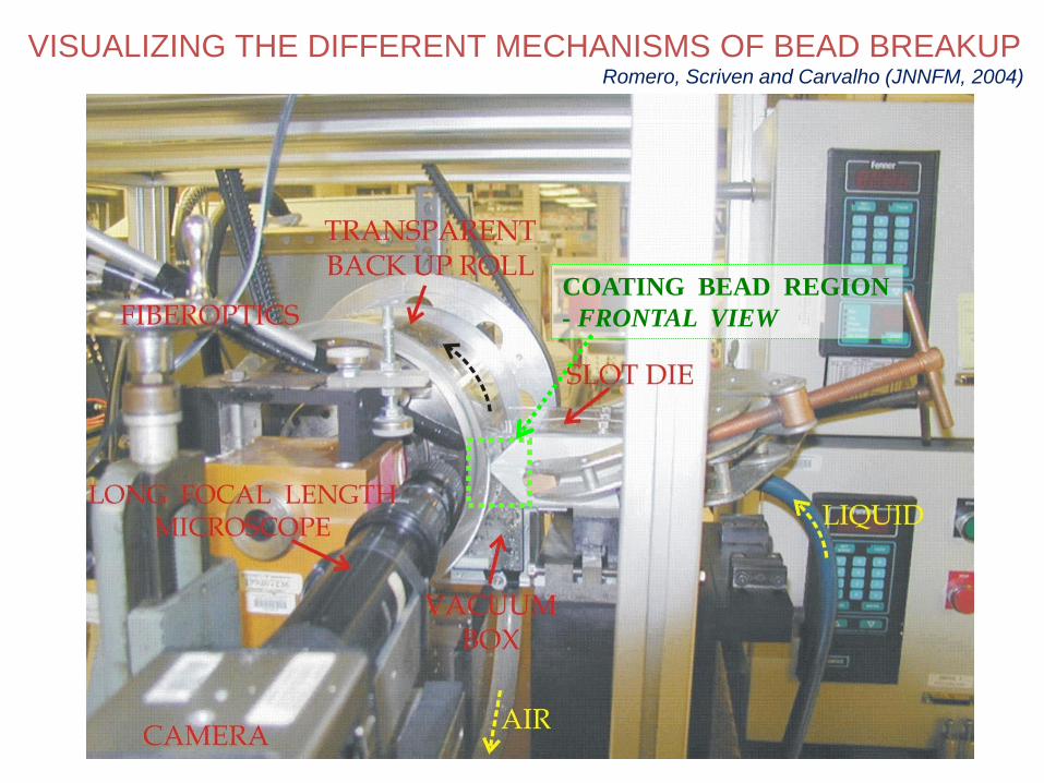
COATING BEAD REGION
- FRONTAL VIEW
VISUALIZING THE DIFFERENT MECHANISMS OF BEAD BREAKUP Romero, Scriven and Carvalho (JNNFM, 2004)

CAMERA
GLASS ROLL
MIRROR
VACUUM BOX
FIBEROPTICS
SIDE PLATE
SLOT DIE 100m

LOWER PRESSURE — “VACUUM”
ATMOSPHERIC PRESSURE
FLOW VIEWED THROUGH GLASS ROLL
RO
LL
MO
TIO
N

INVASION OF THE
UPSTREAM MENISCUS
INVASION OF THE
DOWNSTREAM MENISCUS
(c)
DEFINITIONS OF OPERATING LIMITS
IN SLOT COATING PROCESS

LUBRICATION APPROXIMATION MODEL – Rectilinear Flow
Q
t = Q / V PU
PE
PD
P0
P1
PC
DH
sH
FLOW IN FEED SLOT S
ECs
L
PPHQ
12
3
FLOW UPSTREAM
UH
2120
3
U
U
EUUU
VH
L
PPHQ
EU PPP 00

Couette Poiseuille
VISCOUS FLOW IN SLOT COATING – CONT.
FLOW DOWNSTREAM
DHPE
PD
P1
t = Q / V D
DEDD
D
D
DED
L
PP
V
HHt
VH
L
PPHVtQ
122
212
3
3
IF 0)(for 2
DDED LPP
Ht
IF 0)(for 2
1 DDED LPPP
Ht
ambamb
DEU
PPPP
PPPPP
01
10
IF
DL
VACUUM IS NEEDED, OTHERWISE FLOW BREAKS INTO RIVULETS
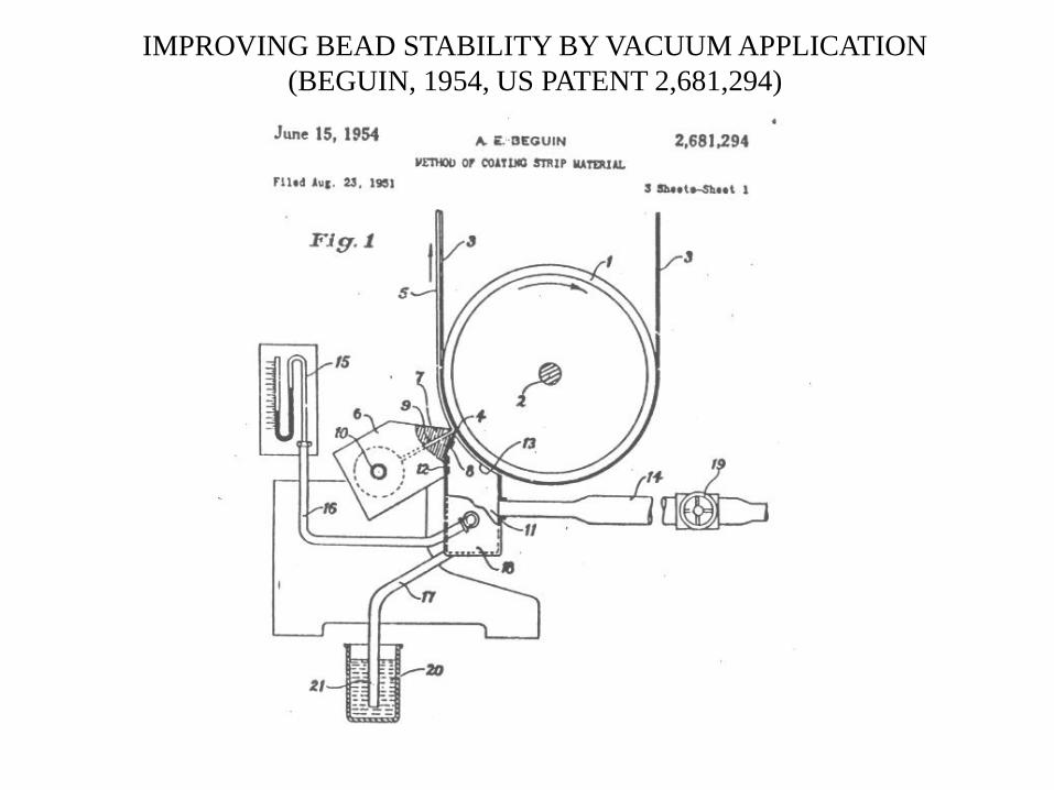
IMPROVING BEAD STABILITY BY VACUUM APPLICATION
(BEGUIN, 1954, US PATENT 2,681,294)
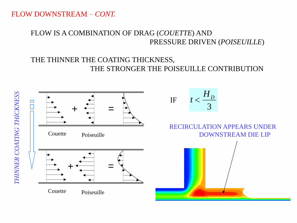
FLOW DOWNSTREAM – CONT.
Couette Poiseuille
+ =
Couette Poiseuille
+ =
FLOW IS A COMBINATION OF DRAG (COUETTE) AND
PRESSURE DRIVEN (POISEUILLE)
THE THINNER THE COATING THICKNESS,
THE STRONGER THE POISEUILLE CONTRIBUTION
TH
INN
ER
CO
AT
ING
TH
ICK
NE
SS
IF 3
DHt
RECIRCULATION APPEARS UNDER
DOWNSTREAM DIE LIP
ULDL
vacP ambP
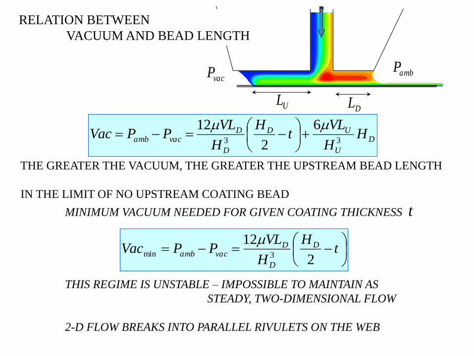
RELATION BETWEEN
VACUUM AND BEAD LENGTH
D
U
UD
D
Dvacamb H
H
VLt
H
H
VLPPVac
33
6
2
12
THE GREATER THE VACUUM, THE GREATER THE UPSTREAM BEAD LENGTH
IN THE LIMIT OF NO UPSTREAM COATING BEAD
MINIMUM VACUUM NEEDED FOR GIVEN COATING THICKNESS t
THIS REGIME IS UNSTABLE – IMPOSSIBLE TO MAINTAIN AS
STEADY, TWO-DIMENSIONAL FLOW
2-D FLOW BREAKS INTO PARALLEL RIVULETS ON THE WEB
t
H
H
VLPPVac D
D
Dvacamb
2
123min

THE GREATER THE UPSTREAM BEAD LENGTH, THE GREATER
THE STABILITY AGAINST RIVULET FLOW, AND THE
GREATER THE ABILITY OF THE COATING BEAD TO
ACCOMMODATE FLUCTUATIONS.
CONCERNS WITH RECIRCULATION, IF PRESENT.
COATING DIES HAVE A FIXED UPSTREAM LIP LENGTH
THERE IS A MAXIMUM VACUUM THAT CAN BE APPLIED BEFORE
THE UPSTREAM BEAD BECOMES TOO LONG AND
INVADES THE VACUUM BOX – WEEPING
PREMETERING IS LOST
THE RANGE OF VACUUM OVER WHICH
SLOT COATER CAN BE OPERATED GIVES
DEFINES THE COATING WINDOW

COATING WINDOW – LOW FLOW LIMIT
BASIC MECHANISM WELL DESCRIBED BY VISCOCAPILLARY MODEL
R
t
H0
V
Q = V t = Qcouette - QPoiseuille
Qcouette = V H0 / 2
Qpoiseuille P2 - P1 = / R
AT A FIXED WEB SPEED, MINIMUM THICKNESS OCCURS WHEN
Qpoiseuille IS MAXIMUM R IS MINIMUM
(1)
(2)
2
0min
tHR
tHPP
0
max12
2
FROM FILM-FLOW EQUATION t
CaPP3/2
12 34.1
AT THE ONSET OF LOW-FLOW LIMIT
2
3
0 1
265.0
tH
VCa

LUBRICATION MODEL CAN BE USED TO PREDICT THE
RANGE OF OPERABILITY FOR DIFFERENT PARAMETERS
FLOW NEAR DOWNSTREAM FREE SURFACE
Couette Poiseuille
DHPE
PD
P1
t = Q / V
DL
R
t
VPPP DD
32
1 34.1
Landau-Levich eq.
Young-Laplace eq.
RPPP DD
1
(1)
(2)
Geometric relation (meniscus is an arc of circle).
1arccos
R
tHD (3)
Flow under downstream die lip
212
3
D
D
DED VH
L
PPHVtQ
2
123
D
D
DDE
Ht
H
VLPP
(4)

FLOW NEAR UPSTREAM FREE SURFACE
2)(120
3
U
DCL
EUUU
VH
X
PPHQ
PE
x
PU
Couette Poiseuille
UH
DCLX
UL
VACU PPP 0
Flow under upstream die lip
Neglect capillary effect on upstream meniscus
xDCL is < 0
2
6U
VACEDCL H
V
PPX
(5)

FAILURE MECHANISMS
VCapillary number
UDCL LX
0DCLX
0(1)
(3)
(2)
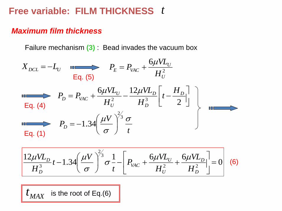
Free variable: FILM THICKNESS t
Maximum film thickness
Failure mechanism (3) : Bead invades the vacuum box
2
6
U
UVACE
H
VLPP
UDCL LX
Eq. (5)
Eq. (4)
2
12632
D
D
D
U
UVACD
Ht
H
VL
H
VLPP
Eq. (1) t
VPD
32
34.1
0661
34.112
22
32
3
D
D
U
UVAC
D
D
H
VL
H
VLP
t
Vt
H
VL
MAXt is the root of Eq.(6)
(6)

Minimum film thickness
Failure mechanism (1) : Downstream meniscus invades coating bead
Or
Failure mechanism (2) : Upstream meniscus invades coating bead
Failure mechanism (1)
211
tHR
R
tH DD
Eq. (1)
and (2)
0Eq. (3)
Rt
V
32
34.1
32
32
)1(
34.12
34.1
V
HV
tD
MIN (7)

Failure mechanism (2)
0DCLXEq. (5)
VACE PP
Eq. (4)
and (2)
2
1234.1
3
32
D
D
DVAC
Ht
H
VL
t
VP
061
34.112
2
32
3
VAC
D
D
D
D PH
VL
t
Vt
H
VL
)2(
MINt is the root of Eq.(8)
(8)
)2()1( ,max MINMINMIN ttt

LOW FLOW LIMIT MAXIMUM WEB SPEED AT A GIVEN FILM THICKNESS
MINIMUM FILM THICKNESS AT A GIVEN WEB SPEED
0.001
0.01
0.1
1
10
0 10 20 30 40 50
Cap
illa
ry N
um
ber
,
V /
Gap / Film Thickness
Stable
Unstable
2
3
0 1
265.0
tH
VCa
THE MAXIMUM POSSIBLE WEB SPEED FALLS AS THE
WET FILM THICKNESS DECREASES
FOR dyn/cm 25 cP; 20 mils; 4 mils; 6.0 0 Ht Vmax = 30 ft/min
VISCOCAPILLARY MODEL VALID ONLY AT LOW CAPILLARY NUMBER
EXPERIMENTS HAVE SHOWN EXAMPLES WHERE THE MODEL
FAILS TO PREDICT THE CORRECT MAXIMUM SPEED
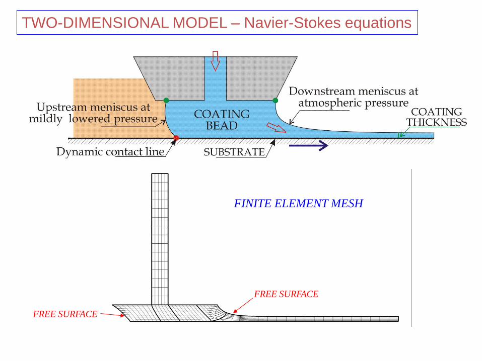
FINITE ELEMENT MESH
FREE SURFACE
FREE SURFACE
TWO-DIMENSIONAL MODEL – Navier-Stokes equations
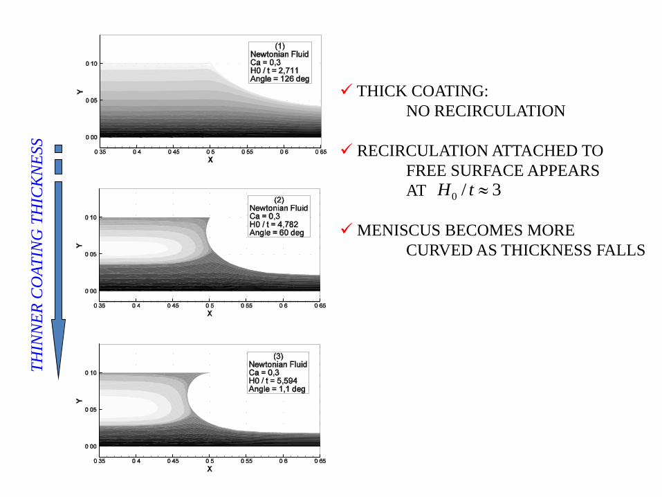
TH
INN
ER
CO
AT
ING
TH
ICK
NE
SS
THICK COATING:
NO RECIRCULATION
RECIRCULATION ATTACHED TO
FREE SURFACE APPEARS
AT
MENISCUS BECOMES MORE
CURVED AS THICKNESS FALLS
3/0 tH
0.45
0.5
0.55
0.6
0.65
0.7
0 0.02 0.04 0.06 0.08 0.1 0.12
Po
siti
on
alo
ng t
he
web
, X
(mm
)
Position across the bead, Y (mm)
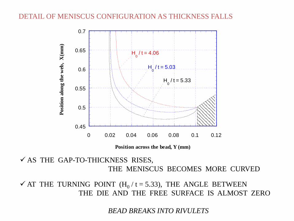
H0 / t = 4.06
H0 / t = 5.03
H0 / t = 5.33
DETAIL OF MENISCUS CONFIGURATION AS THICKNESS FALLS
AS THE GAP-TO-THICKNESS RISES,
THE MENISCUS BECOMES MORE CURVED
AT THE TURNING POINT (H0 / t = 5.33), THE ANGLE BETWEEN
THE DIE AND THE FREE SURFACE IS ALMOST ZERO
BEAD BREAKS INTO RIVULETS

0.001
0.01
0.1
1
10
0 10 20 30 40 50
Viscocapillary Model
Navier-Stokes
Cap
illa
ry N
um
ber
,
V /
Gap / Film Thickness
P = 0 NO INERTIAL EFFECTS
0.01
0.1
1
0 5 10 15 20
Viscocapillary Model
P = 0
P = 381
P = 762
P = 952.5
Cap
illa
ry N
um
ber
,
V /
Gap / Film Thickness
EFFECT OF INERTIA

0.45
0.5
0.55
0.6
0.65
0.7
0 0.02 0.04 0.06 0.08 0.1 0.12
Posi
tion
alo
ng t
he
web
, X
(m
m)
Position across the bead, Y (mm)
Ca = 0.12
Ca = 0.31
Ca = 0.73
Ca = 1.00
DETAIL OF MENISCUS CONFIGURATION AS COATING SPEED RISES
0.01
0.1
1
10
0 5 10 15 20
Viscocapillary Model
= 13 cP
= 17 cP
= 75 cP
= 22 cP
Ca
pil
lary
Nu
mb
er,
V /
Gap / Film Thickness
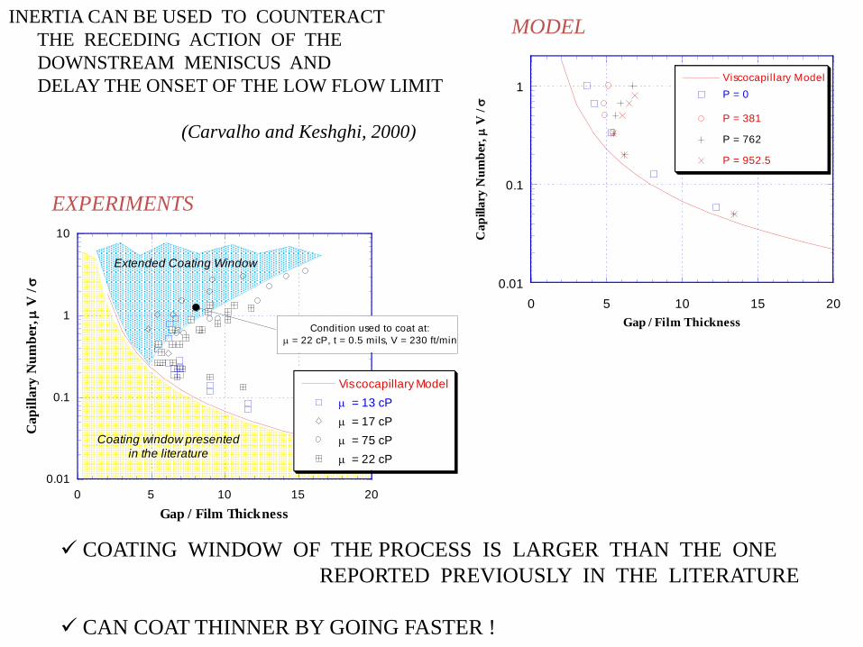
Extended Coating Window
Coating window presented
in the literature
Condition used to coat at:
= 22 cP, t = 0.5 mils, V = 230 ft/min
0.01
0.1
1
0 5 10 15 20
Viscocapillary Model
P = 0
P = 381
P = 762
P = 952.5
Ca
pilla
ry N
um
ber
,
V /
Gap / Film Thickness
EXPERIMENTS
MODEL
COATING WINDOW OF THE PROCESS IS LARGER THAN THE ONE
REPORTED PREVIOUSLY IN THE LITERATURE
CAN COAT THINNER BY GOING FASTER !
INERTIA CAN BE USED TO COUNTERACT
THE RECEDING ACTION OF THE
DOWNSTREAM MENISCUS AND
DELAY THE ONSET OF THE LOW FLOW LIMIT
(Carvalho and Keshghi, 2000)
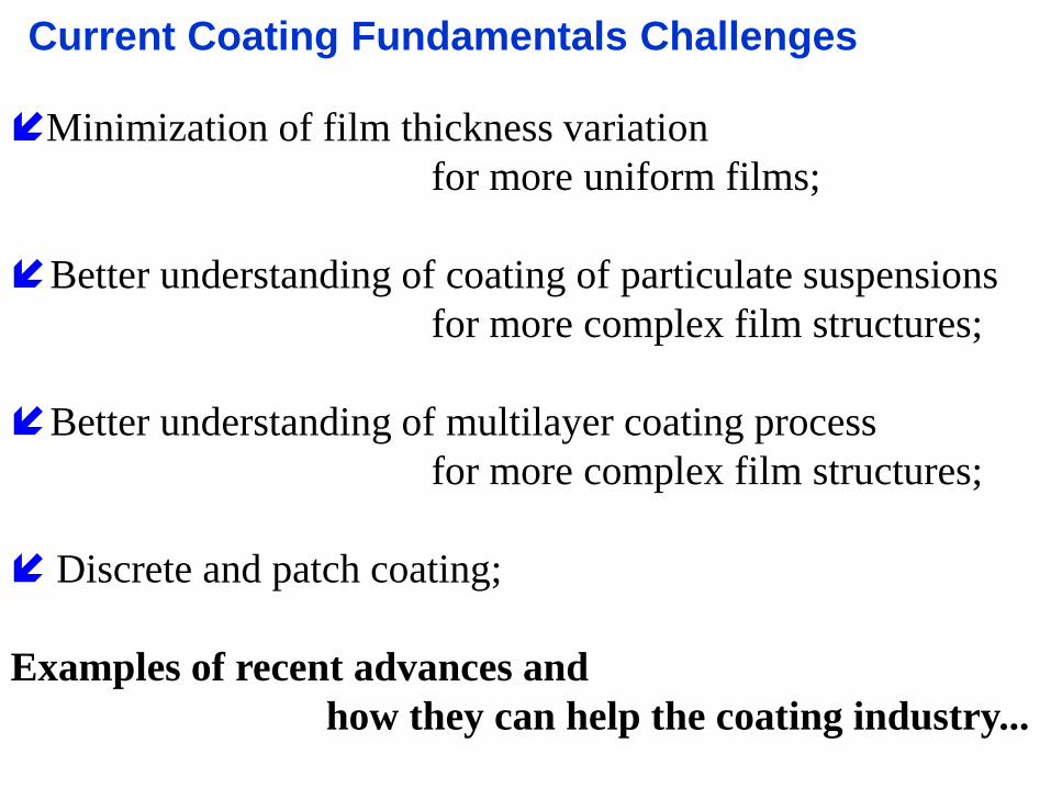
Current Coating Fundamentals Challenges
Minimization of film thickness variation
for more uniform films;
Better understanding of coating of particulate suspensions
for more complex film structures;
Better understanding of multilayer coating process
for more complex film structures;
Discrete and patch coating;
Examples of recent advances and
how they can help the coating industry...
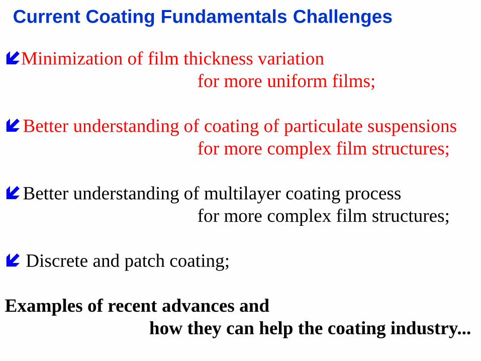

Production lines are subjected to perturbations (even if very small…)
Coating thickness oscillation Gap oscillation
)()( 0 tHHtH m sin )()( 0 thhth msin
Romero e Carvalho (CES, 2008), Perez e Carvalho (JEM, 2011)
Roll radius is not constant, Mechanical vibrations, …
Goal Optimize slot coating process to minimize film thickness variation
due to ongoing disturbances of process conditions;
Transient Response of Coating Flow

Solution Method
Finite Element Method
Implicit time integration –
Newton’s method

Transient Response Hzf 1
Hzf 50
H(t) h(t)
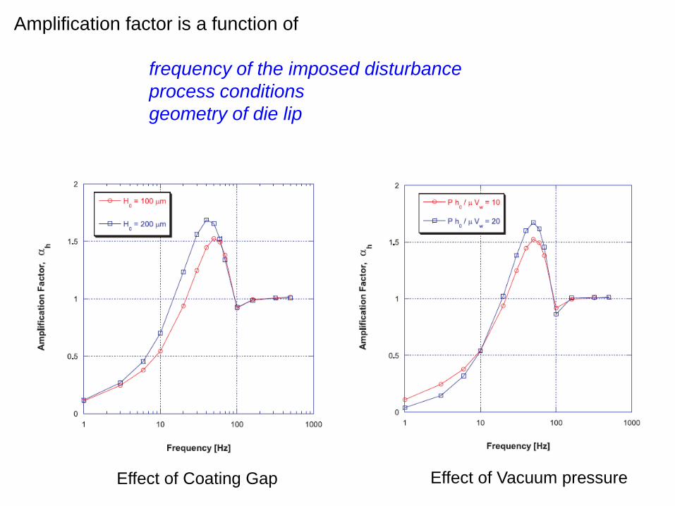
Amplification factor is a function of
frequency of the imposed disturbance
process conditions
geometry of die lip
Effect of Coating Gap Effect of Vacuum pressure

Amplification factor at a given frequency can be mapped as
a function of process conditions.
Gap / Thickness
Dim
ensio
nle
ss V
acuum
Pre
ssure
0,7
0,6
0,5
0,5
0,4
0,4
0,3 0,3
0,20,2
4,03,53,02,52,01,5
40
35
30
25
20
15
10
Amplitude of film thickness oscillation may be reduced by a factor of 5
just by adjusting process conditions.
Hzf 3

Contour plot of amplification factor as a function of gap and vacuum pressure
Hzf 3
Solution has been implemented in a production line at Fuji Film, Japan.
Boundary Constraint Optimization algorithm.
)()()()(2
1)( 00000 xfxxbxxHxxxxq TT
)( 0
2 xfH )( 0xfb
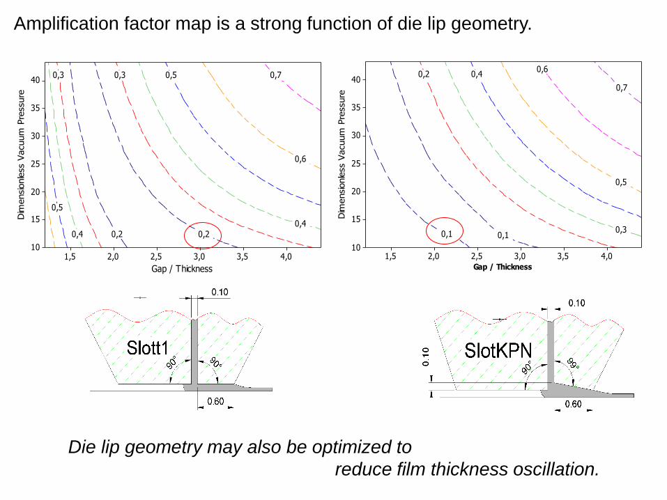
Amplification factor map is a strong function of die lip geometry.
Gap / Thickness
Dim
ensio
nle
ss V
acuum
Pre
ssure
0,7
0,6
0,5
0,5
0,4
0,4
0,3 0,3
0,20,2
4,03,53,02,52,01,5
40
35
30
25
20
15
10
Gap / Thickness
Dim
ensio
nle
ss V
acuum
Pre
ssure
0,7
0,6
0,5
0,4
0,3
0,2
0,1 0,1
4,03,53,02,52,01,5
40
35
30
25
20
15
10
Die lip geometry may also be optimized to
reduce film thickness oscillation.
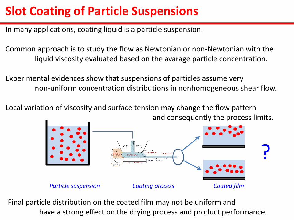
In many applications, coating liquid is a particle suspension. Common approach is to study the flow as Newtonian or non-Newtonian with the liquid viscosity evaluated based on the avarage particle concentration. Experimental evidences show that suspensions of particles assume very non-uniform concentration distributions in nonhomogeneous shear flow. Local variation of viscosity and surface tension may change the flow pattern and consequently the process limits.
Final particle distribution on the coated film may not be uniform and have a strong effect on the drying process and product performance.
Particle suspension Coating process Coated film
?
Slot Coating of Particle Suspensions

MATHEMATICAL MODEL OF COATING FLOW
Momentum conservation
Mass conservation
Particle Transport
0+)(+-- T
cp vvIvv
0= v
0 Nv c
0
0
Nn
nTn
vn
sss cc BCs along interface
)( sc
as first approximation

Particle Transport / Bulk
0 Nv c
Total flux of particles due to different migration mechanisms
Assume neutrally bouyant spherical, rigid particles; Neglect Brownian diffusion – particle size > 0.5 m; Diffuse flux model for particle migration proposed by Phillips et al (PF, 1992); Particle migration by two mechanisms:
1. Spatially varying particle-particle interaction frequency
2. Spatially varying liquid viscosity
NNN c
ccakcc 2N
cdc
dack
ack
22
22 N

Viscosity Model
1.82
1S m
c c
Empirical viscosity model for concentrated suspension developed by Krieger:
- suspension viscosity.
- continuous phase viscosity.
- volume fraction of particles.
- maximum packing fraction of particles. m
c
cs
cP60)(4.0
68.0cP;12
00
cc
cms
In this work:
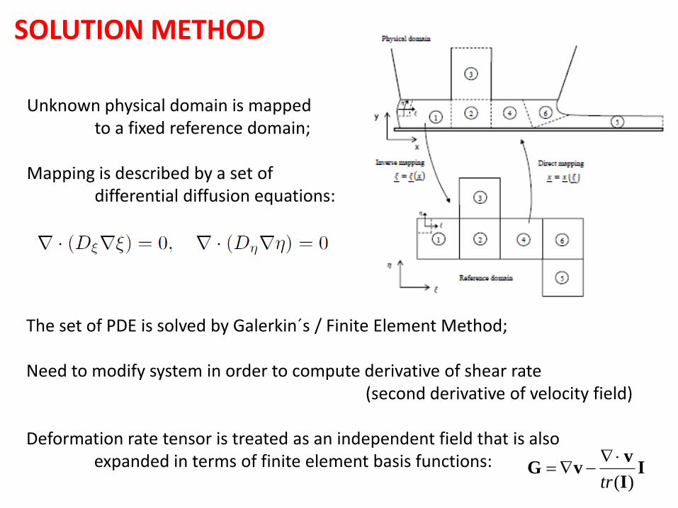
SOLUTION METHOD
Unknown physical domain is mapped to a fixed reference domain; Mapping is described by a set of differential diffusion equations:
The set of PDE is solved by Galerkin´s / Finite Element Method; Need to modify system in order to compute derivative of shear rate (second derivative of velocity field) Deformation rate tensor is treated as an independent field that is also expanded in terms of finite element basis functions: I
I
vvG
)(tr
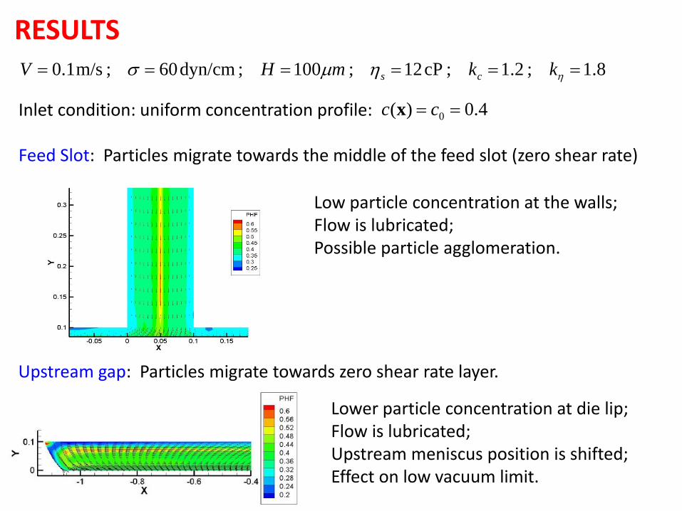
RESULTS
Inlet condition: uniform concentration profile: Feed Slot: Particles migrate towards the middle of the feed slot (zero shear rate)
4.0)( 0 cc x
Low particle concentration at the walls; Flow is lubricated; Possible particle agglomeration.
Upstream gap: Particles migrate towards zero shear rate layer.
Lower particle concentration at die lip; Flow is lubricated; Upstream meniscus position is shifted; Effect on low vacuum limit.
8.1;2.1;cP12;100;dyn/cm60;m/s1.0 kkmHV cs

Film thickness (flow rate) has a strong effect on deformation rate distribution under the die lip; Consequently, it has a strong effect on the particle concentration in the coating bead and final coated layer;
Couette Poiseuille
+ =
Couette Poiseuille
+ =
Couette Poiseuille
+ = TH
INN
ER
CO
AT
ING
TH
ICK
NE
SS
3
0Ht
3
0Ht
2
0Ht
Almost rectilinear flow Couette (drag) + Poiseuille (pressure gradient)
const
0
0

250 0H
mt Film thickness equal to half of the gap
0.35
0.36
0.37
0.38
0.39
0.4
0.41
0.42
0.43
0 0.01 0.02 0.03 0.04 0.05
Co
nce
ntr
atio
n
y
Flux related to shear rate gradient is zero. Weak particle migration after feed slot. High particle concentration at center of feed slot is convected to final coated layer.
Concentration field at coated layer
Region of high particle concentration in the middle of the coated layer. Possible effect on final structure and drying process.

337 0H
mt Film thickness close to one-third of the gap
0.36
0.37
0.38
0.39
0.4
0.41
0.42
0.43
0 0.01 0.02 0.03 0.04
c
y
Strong flux towards the zero-shear rate layer attached to the die lip; High particle concentration attached to the die lip is convected to top of the coated film.
Concentration field at coated layer
Region of high particle concentration on the top of the coated layer. Possible effect on final structure and drying process.

314 0H
mt Film thickness less than one-third of the gap
0.36
0.37
0.38
0.39
0.4
0.41
0.42
0.43
-0.001 0.004 0.009 0.014
c
y
Recirculation under the the die lip; High concentration inside the recirculation (near close packing) – particle agglomeration?; High concentration gradient in the free surface – Strong Marangoni effect ?
Region of high particle concentration on the top of the coated layer.
Final Remarks
Slot coating fundamentals is well understood for two-dimensional, steady-state operation – coating window studies;
Fundamental understanding pays off
objectives need to be well defined for industrial use Coating research is addressing current and more complex issues faced by the coating industry;


Thank you!
You are welcome to visit PUC and Rio de Janeiro
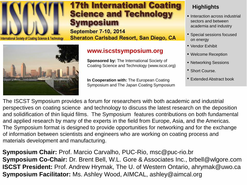
Sponsored by: The International Society of
Coating Science and Technology (www.iscst.org)
In Cooperation with: The European Coating
Symposium and The Japan Coating Symposium
Highlights
Interaction across industrial
sectors and between
academia and industry
Special sessions focused
on energy
Vendor Exhibit
Welcome Reception
Networking Sessions
Short Course.
Extended Abstract book
The ISCST Symposium provides a forum for researchers with both academic and industrial
perspectives on coating science and technology to discuss the latest research on the deposition
and solidification of thin liquid films. The Symposium features contributions on both fundamental
and applied research by many of the experts in the field from Europe, Asia, and the Americas.
The Symposium format is designed to provide opportunities for networking and for the exchange
of information between scientists and engineers who are working on coating process and
materials development and manufacturing.
Symposium Chair: Prof. Marcio Carvalho, PUC-Rio, [email protected]
Symposium Co-Chair: Dr. Brent Bell, W.L. Gore & Associates Inc., [email protected]
ISCST President: Prof. Andrew Hrymak, The U. of Western Ontario, [email protected]
Symposium Facilitator: Ms. Ashley Wood, AIMCAL, [email protected]
www.iscstsymposium.org