fundamentals of electric circuits chapter 11 copyright © the mcgraw-hill companies, inc. permission...
TRANSCRIPT
Fundamentals of Electric CircuitsChapter 11
Copyright © The McGraw-Hill Companies, Inc. Permission required for reproduction or display.

Overview
• This chapter will cover the concept of power in an AC circuit.
• The difference between instantaneous power and average power will be discussed.
• The difference between resistive and reactive power will be introduced.
• Other forms of averaged measurements will be covered
• Apparent power and complex power will also be covered.
2

Instantaneous Power
• This is the power at any instant in time.• It is the rate at which an element absorbs
power• Consider the generalized case where the
voltage and current at the terminals of a circuit are:
• Multiplying the two together, yields:
3
cos cosm v m iv t V t i t I t
1 1cos cos 2
2 2m m v i m m v ip t V I V I t

Instantaneous Power II
• Note that this has two components.– One is constant, depending on the phase
difference between the voltage and current– The second is sinusoidal with a frequency twice
that of the voltage and current.
• A sketch of the possible instantaneous power is below.
4

Instantaneous Power III
• Note that the figure shows times where the power goes negative.
• This is possible with circuit elements like inductors or capacitors which can store and release energy.
• Note also that instantaneous power is very hard to measure as it is constantly changing.
• The more common power measured is average power.
5

Average Power
• Average power is the instantaneous power averaged over a period.
• It is given by:
• When evaluated, this returns the component of instantaneous power that was constant.
• The time dependent part is a sinusoid and thus averages to zero.
6
0
1 T
P p t dtT

Average Power II
• In order to get the instantaneous power, you need to work in the time domain.
• But for average power it is possible to work in frequency domain.
• In this case, the average power is:
7
1 1Re * cos2 2 m m v iP VI V I
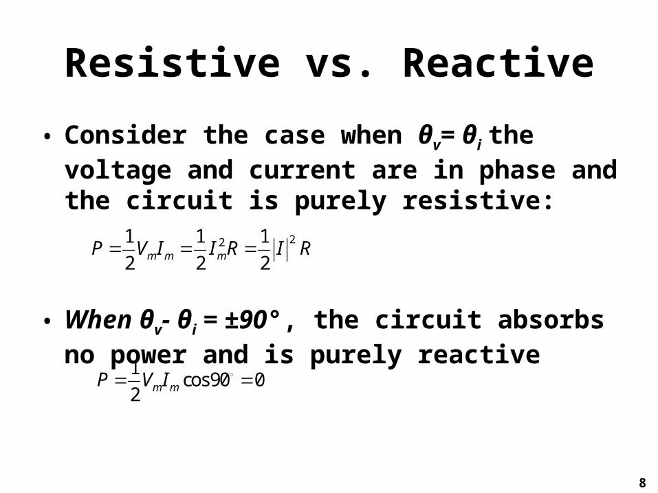
Resistive vs. Reactive
• Consider the case when θv= θi the voltage and current are in phase and the circuit is purely resistive:
• When θv- θi = ±90°, the circuit absorbs no power and is purely reactive
8
221 1 1
2 2 2m m mP V I I R I R
1cos90 0
2 m mP V I

Maximum Average Power Transfer
• Previously we considered how to maximize power delivered to a resistive load.
• It was shown that maximum power was transferred when the load resistance equaled the Thevenin resistance of the supply circuit.
• This will now be extended to AC circuits.
9
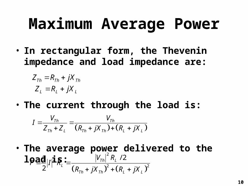
Maximum Average Power
• In rectangular form, the Thevenin impedance and load impedance are:
• The current through the load is:
• The average power delivered to the load is:
10
Th Th Th
L L L
Z R jX
Z R jX
Th Th
Th L Th Th L L
V VIZ Z R jX R jX
22
2 2
/ 21
2Th L
L
Th Th L L
V RP I R
R jX R jX

Maximum Average Power II
• We want to find the peak in this function, which means finding the derivative and identifying where it goes to zero.
• This must be done for both RL and XL.
• For ∂P/∂XL
• For ∂P/∂RL
11
2
22 2
Th L Th L
LTh Th L L
V R X XP
X R jX R jX
2 22
22 2
2Th Th L Th L L Th L
LTh Th L L
V R R X X R R RP
R R jX R jX

Maximum Average Power III
• Combining these one finds that XL=-XTh and RL=RTh satisfy the requirements:
• The load impedance must be equal to the complex conjugate of the Thevenin impedance.
• The maximum average power will be:
12
*L L L Th Th ThZ R jX R jX Z
2
max 8Th
Th
VP
R

Effective Value• When a time varying source is delivering
power to a resistive load, we often want to know the effectiveness of that source on delivering power.
• This value is the DC current that delivers the same average power to a resistor as the periodic current
• For a periodic current, the average power absorbed is:
13
2 21 T T
o o
RP i Rdt i dt
T T

Average Power
• For a DC current, the average power absorbed is:
• Equating these two and solving for the effective DC current yields:
• The effective voltage is found in a similar manner:
14
2effP i R
2
0
1 T
effI i dtT
2
0
1 T
effV v dtT

RMS
• The effective values for both current and voltage take the form of the square root of the average of the square of the periodic signal.
• This is typically referred to as the root mean square, or RMS value for short.
• This can be extended to any periodic function:
15
2
0
1 T
rmsX x dtT

RMS II• If the parameter of interest is a constant, the
RMS value will be that constant.• The RMS value is applicable to any periodic
function, regardless of its shape.• However, for a sinusoidal waveform, the RNS
value is related to the amplitude as follows:
• RMS power can be determined from either RMS current or voltage:
16
2m
rms
VV
22 rmsrms
VP I R
R

Apparent Power
• The product of RMS voltage and current will be called apparent power.
• Note that this is modulated by the phase difference:
• This will be referred to as the power factor.
17
iv cos

Apparent Power II
• Apparent power is called that simply because that is what the power in the circuit would seem to be.
• It is measured in VA, to distinguish it from the average or real power.
• The angle θv-θi is called the power factor angle.
• This is equal to the angle of the load impedance is V is the voltage across the load and I is the current through it.
18

Power Factor
• The power factor can range from zero to unity.
• In a case where the power factor angle is positive, the current leads the voltage, and vice versa for negative angles.
• Purely reactive loads will have a power factor of zero.
• Power factors affect the way utilities bill for electricity.
19

Complex Power
• The term complex power refers to the total effect of parallel loads on power.
• The complex power, S, absorbed by an AC load is:
• This may also be expressed in terms of the RMS values and load impedance as:
20
*1
2S VI
22 *
*rms
rms rms rms
VS I Z V I
Z

Complex Power II
• The complex power expressed in rectangular form is:
• Where:
• P is the average or real power• Q depends on the load’s reactance and is
called reactive (or quadrature) power
21
2rmsS I R jX P jQ
2
2
Re
Imrms
rms
P S I R
Q S I X

Real and Reactive Power
• The real power is the only useful power. It is measured in watts.
• The reactive power is a measure of the energy exchange between the source anf the reactive load.
• It is measured in units of volt-ampere reactive (VAR)
22

Summarizing Power
23
2 2
Complex Power *
Apparent Power
Real Power Re cos
Reactive Power Im sin
Power Factor cos
rms rms
rms rms v i
rms rms
v i
v i
v i
S P jQ V I
V I
S S V I P Q
P S S
Q S S
P
S

Conservation of AC Power
• Regardless of how circuit elements are connected, the total complex power delivered is equal to the total complex power absorbed by the elements.
• The same is true of real and reactive power, but not of apparent power.
24
1 2 3 NS S S S S

Power Factor Correction
• Most domestic and industrial loads, such as washing machines, air conditioners, and induction motors are inductive.
• They have a low, lagging power factor.• The load cannot be changed, but the power
factor can be increased without altering the voltage or current to the original load.
• This is referred to as power factor correction.
25

Adding a Capacitor
• To mitigate the inductive aspect of the load, a capacitor is added in parallel with the load.
• Looking at the phasor diagram, showing before and after adding the capacitor, the power factor has improved.
26

Adding a Capacitor II
• With the same supplied voltage, the current draw is less by adding the capacitor.
• Since power companies charge more for larger currents because it leads to larger power losses.
• Overall, the power factor correction benefits the power company and the consumer.
• By choosing a suitable size for the capacitor, the power factor can be made to be unity.
27

Adding a Capacitor III
• The capacitor needed in order to shift the power factor angle from θ1 to θ2 is:
• Note that the real power dissipated in the load is not affected by the shunt capacitor.
• Although it is not as common, if a load is capacitive in nature, the same treatment with an inductor can be used.
28
1 22 2
tan tanC
rms rms
PQC
V V

Wattmeter
• Power consumption in a AC system can be measured using a Wattmeter.
• The meter consists of two coils; the current and voltage coils.
• The current coil is designed with low impedance and is connected in series with the load.
• The voltage coil is designed with very large impedance and is connected in parallel with the load.
29

Wattmeter II
• The induced magnetic field from both causes a deflection in the current coil.
• Ideally, the configuration does not alter the load and affect the power measured.
• The physical inertia of the moving coil results in the output being equal to the average power.
30
Immunity Copyright © The McGraw-Hill Companies, Inc. Permission required for reproduction or display
© Lifesize/Getty RF Copyright 2016 © McGraw-Hill Education. Permission required for reproduction or…