fundamentals of chilled beams ansi/ashrae standard...
TRANSCRIPT
© NEMIC 2017
FUNDAMENTALS OF CHILLED BEAMS
ANSI/ASHRAE STANDARD 200-2015, METHODS OF TESTING CHILLED BEAMS

© NEMIC 20172 |
Hello!I am Davor Novosel
I am here because I love to share what I know about chilled beams with you.
You can find me at:[email protected]
© NEMIC 20173 |
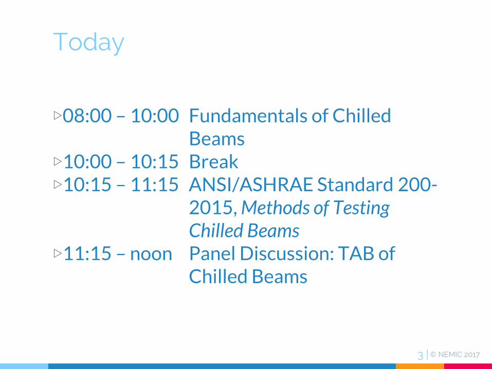
Today
▷08:00 – 10:00 Fundamentals of Chilled Beams
▷10:00 – 10:15 Break▷10:15 – 11:15 ANSI/ASHRAE Standard 200-
2015, Methods of Testing Chilled Beams
▷11:15 – noon Panel Discussion: TAB of Chilled Beams

© NEMIC 2017
FUNDAMENTALS OF CHILLED BEAMS

© NEMIC 20175 |
Agenda
▷1. Concept▷2. Passive Chilled Beam▷3. Active Chilled Beam▷4. Applications▷5. System Design▷6. Passive Beam Selection▷7. Active Beam Selection▷8. Commissioning▷9. Example

© NEMIC 20176 |
References
▷ Alexander, D. 2008. Design Considerations for Active Chilled Beams.ASHRAE Journal 50 (11): 50-58
▷ Brzezenski, SP. 2012. Chilled Beams in Historic Buildings. ASHRAE Journal 54 (11): 48-55
▷ Danfoss Application Guide - Hydronic balancing solutions
▷ Price Industries. 2017. Active & Passive Beams Engineering Guide
▷ REHVA_ASHRAE. 2014. Active and Passive Beam Application Design Guide
▷ Schurk, D. 2012. Chilled Beams Application and Control
▷ SEMCO. 2017. NEUTONTM Brochure. Controlled Chilled Beam Pump Module
▷ Setty, BS. 2011. Application Issues for Chilled Beam Technologies. ASHRAE Transactions, 117 (1)
▷ Trane. 2011. Understanding Chilled Beams Systems. Engineers newsletter 38-4
▷ Trox. 2009. Chilled Beams Design Guide
▷ Vastyan, J. 2011. Chilled Beams Basics. HPAC Engineering (July): 26-28, 42

© NEMIC 20177 |
1.CONCEPT

© NEMIC 20178 |
A Brief History …
Willis Carrier induction unit
First radiant ceiling system by Norwegian engineer Gunnar Frenger
1920s 1940s 1960s
The first radiant ceiling installed in Gothenburg, Sweden
1972
The first radiant cooling device installed in Gothenburg, Sweden
The first passive chilled beam installed in Stockholm, Sweden
1986 1990s
Rapid spread in Europe
2000s
Introduced in USA by Trox

© NEMIC 20179 |
Chilled beam = Linear induction unit

© NEMIC 201710 |
Early 20th century perimeter induction unit

© NEMIC 201711 |
Tuttle & BaileyInduction air terminal unit
TitusFan-powered induction unit
© NEMIC 201712 |
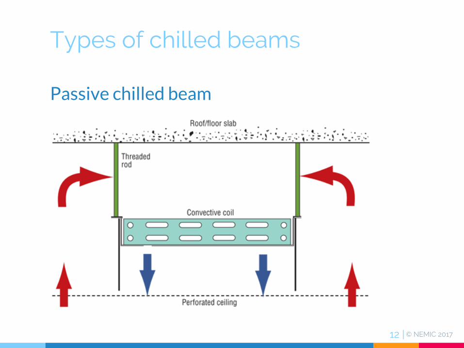
Types of chilled beams
Passive chilled beam

© NEMIC 201713 |

© NEMIC 201714 |
Types of chilled beams
Active chilled beam

© NEMIC 201715 |

© NEMIC 201716 |
Types of chilled beams
Multi service chilled beam

© NEMIC 201717 |

© NEMIC 201718 |
Why beams? Physics!
Water carries significantly more energy than air.
Approximate comparison between water and air transporting equivalent energy

© NEMIC 201719 |
Why beams?
▷… results in more efficient HVAC system with lower operating costs (?!)
Virginia Commonwealth Universitynew school of medicine; energy modeling by Sera Engineering

© NEMIC 201720 |
2. PASSIVE CHILLED BEAM
© NEMIC 201721 |
2. Passive Chilled Beam
▷Passive beams provide sensible cooling from the water coil. ▷Heating and ventilation must be handled by complementing systems.
© NEMIC 201722 |
2. Passive Chilled Beam
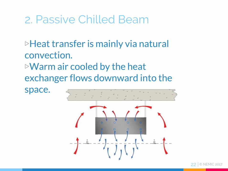
▷Heat transfer is mainly via natural convection.▷Warm air cooled by the heat exchanger flows downward into the space.

© NEMIC 201723 |
2. Passive Chilled Beam
Room air flow pattern of a passive beam in cooling

© NEMIC 201724 |
2. Passive Chilled Beam
Components of a typical passive chilled beam
© NEMIC 201725 |
2. Passive Chilled Beam
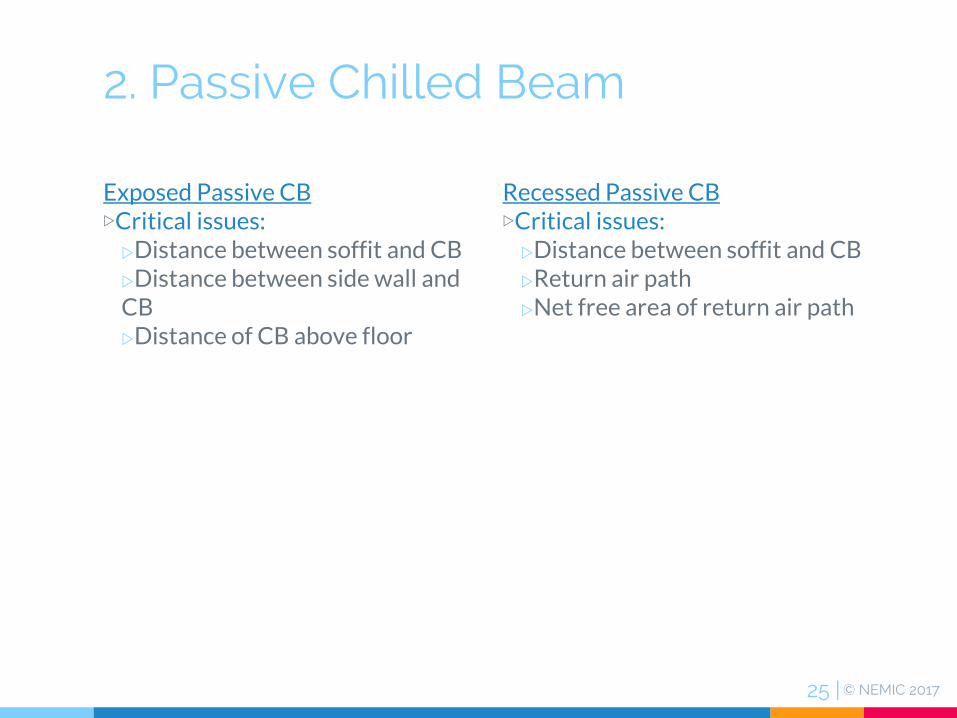
Exposed Passive CB▷Critical issues:wDistance between soffit and CBwDistance between side wall and CBwDistance of CB above floor
Recessed Passive CB▷Critical issues:wDistance between soffit and CBwReturn air pathwNet free area of return air path

© NEMIC 201726 |
2. Passive Chilled Beam
Roof / Ceiling
B
Z > 0.25 B
Z > 0.5 B
Floor
< 14 ft
Exposed Passive CB

© NEMIC 201727 |
2. Passive Chilled Beam
Roof / Ceiling
B
Z > 0.25 B
Recessed Passive CB
Z ≥ 0.5 B suspended ceilingZ ≥ 0.5 B

© NEMIC 201728 |
3. ACTIVE CHILLED BEAM

© NEMIC 201729 |
3. Active Chilled Beam
▷Active beams are connected to both the primary air as well as the chilled- and heated-water systems ▷Constant volume supply air system▷Chilled water temperature > space dew point▷Requires dedicated outdoor air system to remove all (external + internal) latent loads

© NEMIC 201730 |
3. Active Chilled Beam
▷Active beams heat or cool a space through induction and forced convection.

© NEMIC 201731 |
3. Active Chilled Beam
Room air flow pattern of a typical linear active beam in cooling
© NEMIC 201732 |
3. Active Chilled Beam
ACTIVE BEAM TYPES▷Ceiling mounted
wOne-way and two-way discharge unitswFour-way discharge units
▷Bulkhead chilled beam
Other type of active beams are ▷Floor mounted▷Perimeter wall

© NEMIC 201733 |
3. Active Chilled Beam
Trox 2-way CB
Frenger Systems Halo™ -Active Chilled Beam
© NEMIC 201734 |
3. Active Chilled Beam
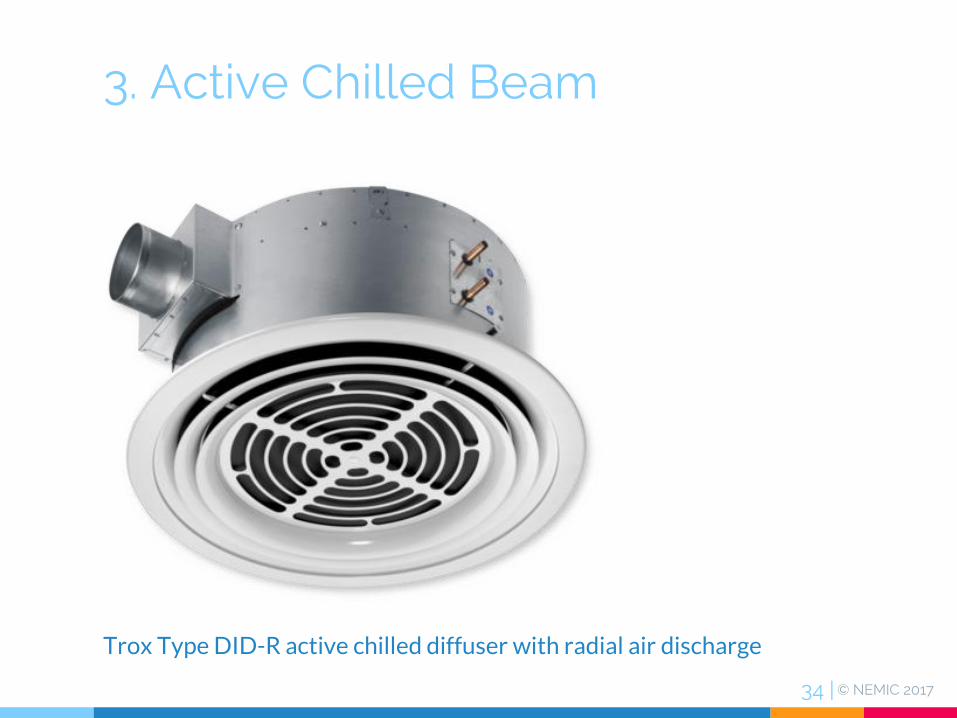
Trox Type DID-R active chilled diffuser with radial air discharge

© NEMIC 201735 |
3. Active Chilled Beam
Price ACBV Vertical Active Beam/Induction Unit

© NEMIC 201736 |
4. APPLICATIONS

© NEMIC 201737 |
4. Applications
Active beams are a good choice for the following applications:▷Spaces with typical heating and sensible cooling requirements▷Buildings with moderate internal latent loads▷Spaces with limited floor-to-ceiling heights▷Spaces where low noise levels are desired

© NEMIC 201738 |
4. Applications
Suitable building types for active CBs:▷Commercial office buildings▷Schools▷Hospital patient rooms▷Laboratories with high internal loads▷Hotels, dormitories

© NEMIC 201739 |
4. Applications
Applications NOT suitable for CBs:▷Building areas where humidity can be difficult to control (lobbies, atria, egress routes)▷Spaces with high latent loads (pools, etc.)▷Applications with high airflow/ventilation requirements, such as an exhaust driven lab▷Kitchens▷Data centers▷Spaces with high ceilings ( > 14ft.)

© NEMIC 201740 |
4. Applications
Passive beams are ideally suited to aisle ways or perimeters of large spaces, such as ▷Offices▷Lobbies▷Conference centers▷Libraries▷Any other space that requires perimeter or additional cooling

© NEMIC 201741 |
4. Applications
Humidity control at all timesis paramount to proper operation of chilled beam systems▷Dew point controller▷No weekend shutdowns▷Building pressurized at all times

© NEMIC 201742 |
4. Applications
When humidity controls fails …

© NEMIC 201743 |
4. Applications
… of chilled beams by climate zones
Easy
Medium: hot, humid summers
Difficult: humid to tropical climate

© NEMIC 201744 |
4. Applications
Condensation risks▷Near entry points▷At perimeter, mixed-mode ventilation▷Building retrofits with leaky envelope▷Spaces with high variable latent loads:
wLunch, coffee roomswMeeting rooms

© NEMIC 201745 |
4. Applications
Condensation prevention▷System meets 100% latent load at peak dew point design▷Limit overcooling▷Chilled water shut-off or reset ▷Reset air temperature▷VAV for variable occupancy

© NEMIC 201746 |
4. Applications
Condensation prevention▷Chilled water reset in response to space dew point

© NEMIC 201747 |
5. SYSTEM DESIGN

© NEMIC 201748 |
5. System Design
Chilled beam systems require▷Source of chilled water at two different temperatures▷Source of hot water (4 pipe system)▷Supply of primary air

© NEMIC 201749 |
42°F54°F
DOAS
56°F62°F
By-pass
By-pass
Active CB
5. Chilled Water System Design
Dedicated Chillers▷Two independent chilled water loops▷Allows for smaller chiller servicing ACB loop▷Allows for high chiller efficiency of the ACB loop▷Higher first cost
ACB Loop

© NEMIC 201750 |
54°F42°F
DOAS
62°F
56°F
5. Chilled Water System Design
Common chiller▷Chiller downsizing not possible▷Lower EER compared to separate loops▷Higher supply water temperature not feasible▷DOAS load significantly higher the ACB loop one
ACB Loop

© NEMIC 201751 |
54°F 42°F
DOAS
62°F
56°F
5. Chilled Water System Design
Common chiller with heat exchanger ▷Chiller downsizing not possible▷Lower EER compared to separate loops▷Higher supply water temperature not feasible▷DOAS load significantly higher the ACB loop one▷Requirement for isolated chilled water loops
By-pass
Controlvalve
ACB Loop

© NEMIC 201752 |
Packaged DOAS
62°F 56°F
By-pass
Active CB
5. Chilled Water System Design
Chiller / Decouples DOAS▷Allows for smaller chiller servicing ACB loop▷Allows for high chiller efficiency of the ACB loop
ACB Loop

© NEMIC 201753 |
5. Chilled Water System Design
Source: SEMCO® A Fläkt Woods Company. 5504ASCENDANT Health Care Brochure - SEMCO 2016-02

© NEMIC 201754 |
5. Chilled Water System Design
Primary airflow (PA) is based on largest of:▷Minimum outdoor airflow required (ASHRAE 62.1)▷Airflow required to offset space latent load (depends on dew point of PA)▷Airflow needed to induce sufficient room air (RA) to offset the space sensible cooling load
PA
RA SA

© NEMIC 201755 |
5. System Design-Controls
Beam system controls typically include the following:▷Zone control▷Beam water temperature control▷Primary air-conditioning control▷Condensation prevention

© NEMIC 201756 |
5. System Design-Controls
Airside Control▷Primary airwUse fully self-contained volume flow limiter (VFL) wVFL’s are recommended when an AHU also supplies VAV terminals.
▷Monitor space dew pointwUse small quantity of high quality sensorswDo not use rel. humidity sensorsw Locate sensors in room not in ceiling
▷Reduce primary moisture content to control space rel. humiditywDOAS

© NEMIC 201757 |
5. System Design-Controls
Volume flow limiter (VFL)

© NEMIC 201758 |
5. System Design-Controls
Monitor space dew point

© NEMIC 201759 |
5. System Design-Controls
Waterside Control▷Variable water flow
wPressure independent control
▷Two position valves or modulating valves▷6-way valves can be used on 4 pipe into 2 pipechilled beams▷Reschedule or shut off chilled beam water supply only if primary moisture content cannot reduced
© NEMIC 201760 |
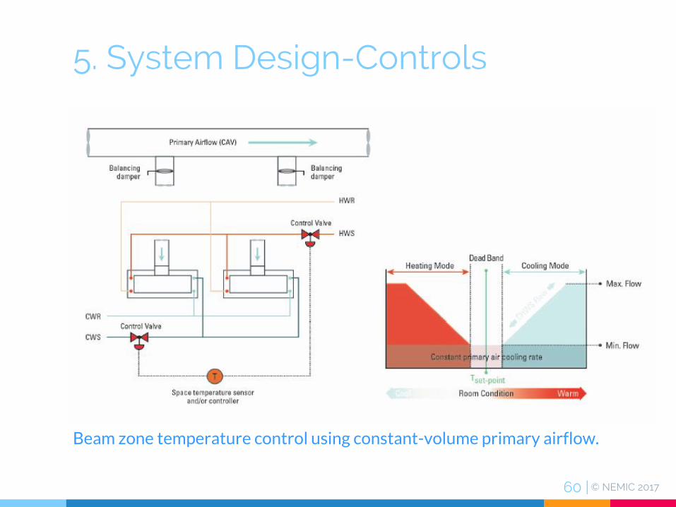
5. System Design-Controls
Beam zone temperature control using constant-volume primary airflow.

© NEMIC 201761 |
5. System Design-Controls
Beam zone temperature control using variable volume primary airflow.
© NEMIC 201762 |
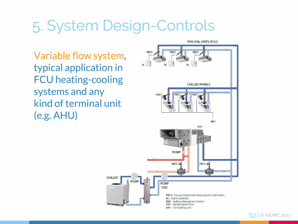
5. System Design-Controls
Variable flow system, typical application in FCU heating-cooling systems and anykind of terminal unit (e.g. AHU)

© NEMIC 201763 |
5. System Design-Controls
Constant flow system, typical application in FCU heating-cooling systems and in AHU

© NEMIC 201764 |
5. System Design-Controls

© NEMIC 201765 |
5. System Design-Controls
Heating with active chilled beams

© NEMIC 201766 |
5. System Design-Controls
Heating with active chilled beams▷Active CB available in 2-pipe or 4-pipe configuration▷Application limited by output capacity:
wZones < 300 Btu/h/ft²
wZones 300 – 400 Btu/h/ft² Air discharge towards window at 75fpm
wZones > 400 Btu/h/ft²

© NEMIC 201767 |
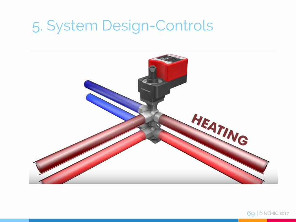
5. System Design-Controls
▷ 6-way ball valve is a combination valve for connecting heating and cooling 4 pipe system into a single coil

© NEMIC 201768 |
5. System Design-Controls
© NEMIC 201769 |
5. System Design-Controls

© NEMIC 201770 |
6. PASSIVE BEAM SELECTION

© NEMIC 201771 |
6. Passive Beam Selection
The performance of a passive beam is dependent on several factors:▷Water flow rate▷Mean water temperature and surrounding air temperature▷Shroud height▷Free area of the air paths (internal and external to the beam)▷Location and application

© NEMIC 201772 |
6. Passive Beam Selection
,
Room Temperature 74 °F to 78 °F in summer, 68 °F to 72 °F in winter
Water Temperatures Cooling 55 °F to 58 °F EWT, 5 °F to 8 °F ∆T
Design Sound Levels < 40 NC
Cooling Capacity ≤ 500 Btu/h ftCB
Ventilation Requirement 0.1 to 0.5 cfm/ft2 floor area
General Application Parameters

© NEMIC 201773 |
6. Passive Beam Selection
The difference between the mean water temperature, t ̅w, defined as:
𝑡𝑤 =𝑡𝑠𝑢𝑝𝑝𝑙𝑦
+𝑡𝑟𝑒𝑡𝑢𝑟𝑛
2
and the surrounding (coil inlet) airtemperature is one of the primary drivers of the beam performance

© NEMIC 201774 |
6. Passive Beam Selection
Passive beam capacity vs. vs. difference between mean water and room air temperature

© NEMIC 201775 |
6. Passive Beam Selection
Passive beam capacity vs. water flow

© NEMIC 201776 |
6. Passive Beam Selection
where
Re = Reynolds Number (non dimensional)
u = velocity (ft/s)
dh = hydraulic diameter (ft)
ν = kinematic viscosity (ft2/s)
𝑅𝑒 =𝑢 𝑑ℎ𝑣
Temperature(oF)
Kinematic Viscosity
- ν -(10-5 ft2/s)
32 1.924
40 1.664
50 1.407
60 1.210
70 1.052
80 0.926
90 0.823
100 0.738
120 0.607
140 0.511
160 0.439
180 0.383
200 0.339
212 0.317
Below are two links to online Reynolds Number Calculators.Reynolds Number CalculatorReynolds Number Calculator

© NEMIC 201777 |
6. Passive Beam Selection
Factors that affect performanceof passive beams
A passive beam installed abovea perforated ceiling

© NEMIC 201778 |
6. Passive Beam Selection
The impact on the capacity of the gap between a passive beam and building structure
© NEMIC 201779 |
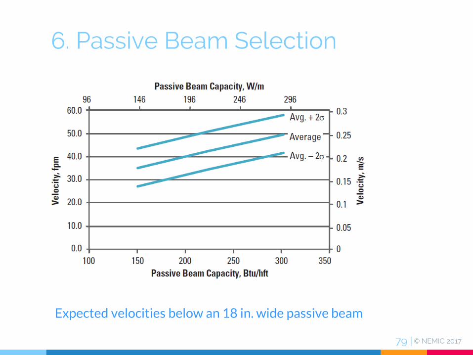
6. Passive Beam Selection
Expected velocities below an 18 in. wide passive beam

© NEMIC 201780 |
7. ACTIVE BEAM SELECTION

© NEMIC 201781 |
7. Active Beam Selection
The performance of an active beam is dependent on several factors:▷Active beam configuration▷Coil circuitry▷Primary air flow (plenum pressure)▷Water flow

© NEMIC 201782 |
7. Active Beam Selection
,
Room Temperature 74 °F to 78 °F in summer, 68 °F to 72 °F in winter
Water Temperatures Cooling 55 °F to 58 °F EWT, 5 °F to 8 °F ∆T
Design Sound Levels < 40 NC
Cooling Capacity ≤ 1,000 Btu/h ftCB
Water Temperature Heating 110 °F to 130 °F EWT, 10 °F to 20 °F ∆T
Heating Capacity ≤ 1,500 Btu/h ftCB
Ventilation Requirement 0.1 to 0.5 cfm/ft2 floor area
Ventilation Capability 5 to 30 cfm/ft
Primary Air Supply Temp. 50 °F to 65 °F
Inlet Static Pressure 0.2 in. w.g. to 1.0 in. w.g. external
General Application Parameters
© NEMIC 201783 |
7. Active Beam Selection
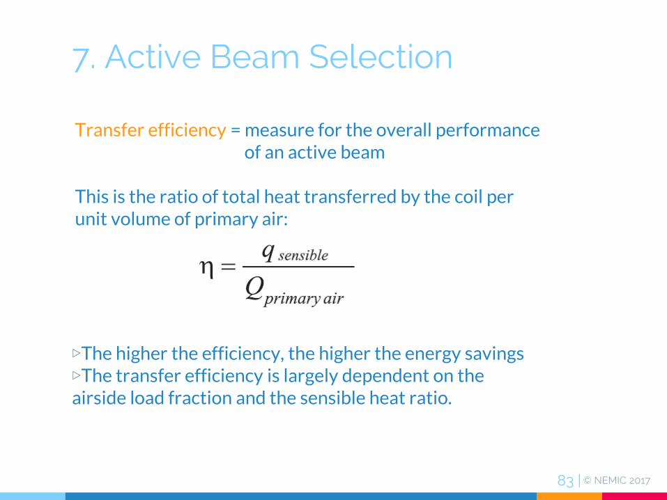
▷The higher the efficiency, the higher the energy savings ▷The transfer efficiency is largely dependent on the airside load fraction and the sensible heat ratio.
Transfer efficiency = measure for the overall performance of an active beam
This is the ratio of total heat transferred by the coil per unit volume of primary air:
© NEMIC 201784 |
7. Active Beam Selection
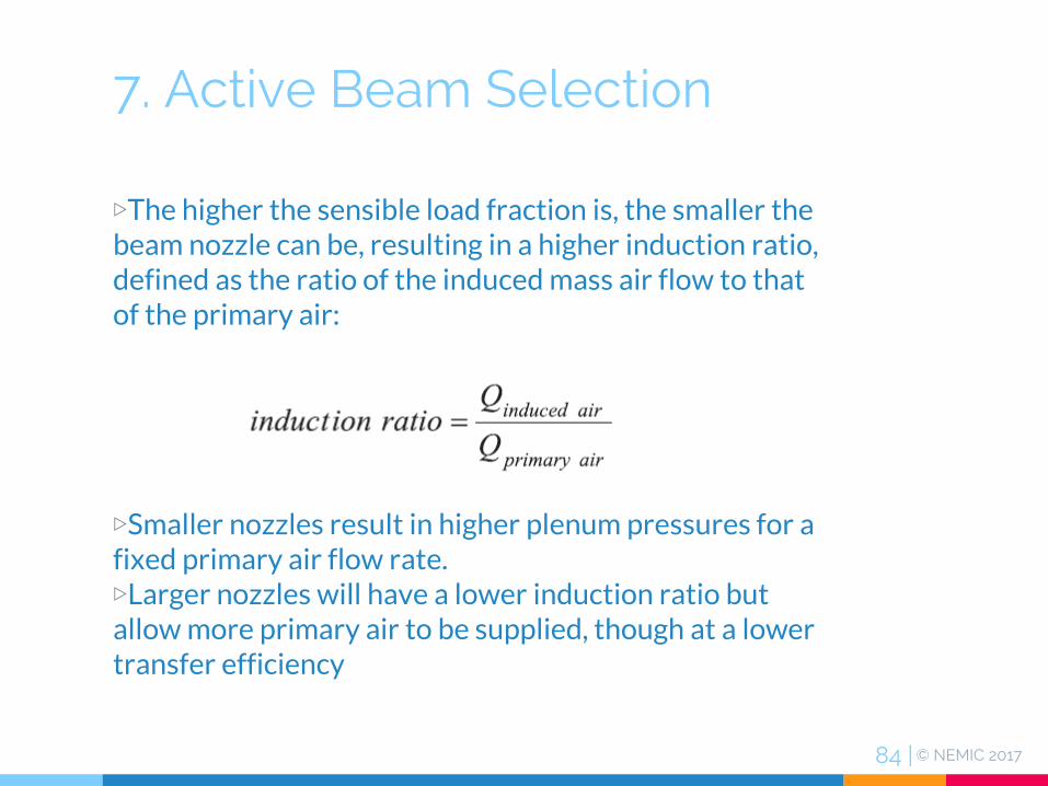
▷The higher the sensible load fraction is, the smaller the beam nozzle can be, resulting in a higher induction ratio, defined as the ratio of the induced mass air flow to that of the primary air:
▷Smaller nozzles result in higher plenum pressures for a fixed primary air flow rate. ▷Larger nozzles will have a lower induction ratio but allow more primary air to be supplied, though at a lower transfer efficiency

© NEMIC 201785 |
7. Active Beam Selection
Transfer efficiency is reduced by increasing nozzle size

© NEMIC 201786 |
7. Active Beam Selection
Capacity of a typical active beam vs. primary air flow
Increased nozzle size
© NEMIC 201787 |
7. Active Beam Selection
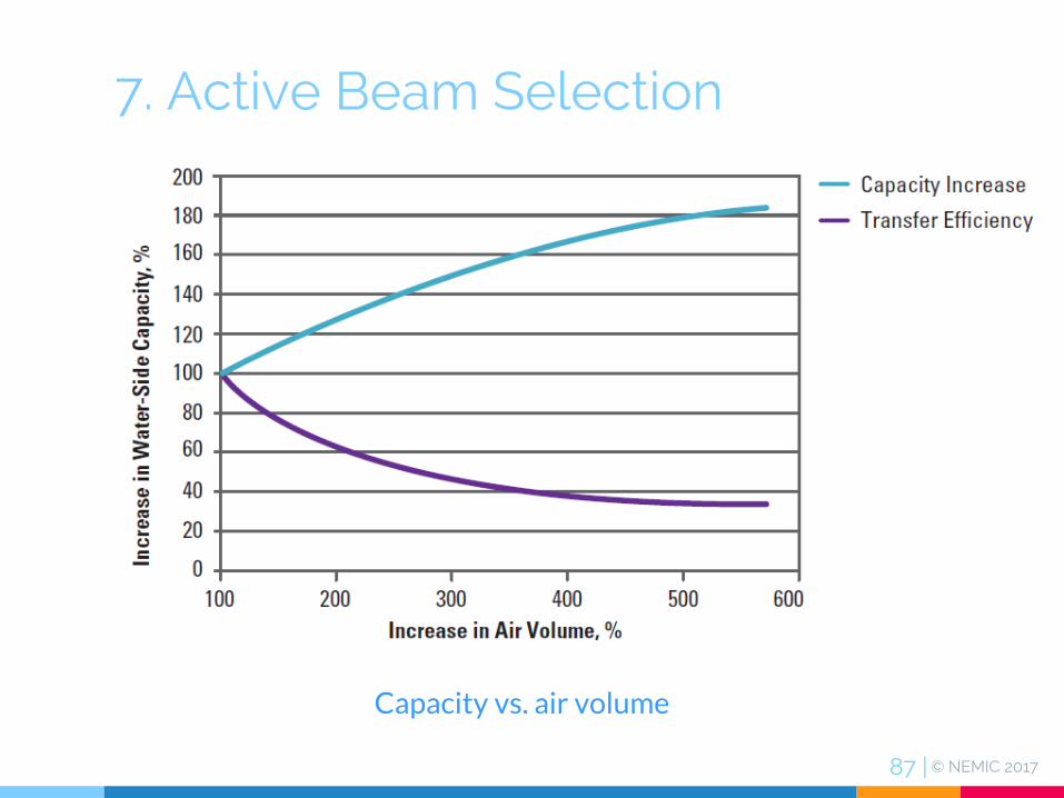
Capacity vs. air volume

© NEMIC 201788 |
7. Active Beam Selection
Active beam capacity vs. water flow

© NEMIC 201789 |
7. Active Beam Selection
Active beam capacity vs. difference between the mean water and room air temperatures

© NEMIC 201790 |
8. COMMISSIONING
© NEMIC 201791 |
8. Commissioning
Initial steps should ensure that▷the coil is free of dust and debris by visual inspection▷the beam is free of all transportation packaging.▷the primary air supply rate and temperature is within tolerance.▷the supply water flow rate(s) and temperature(s) are within tolerance
© NEMIC 201792 |
8. Commissioning
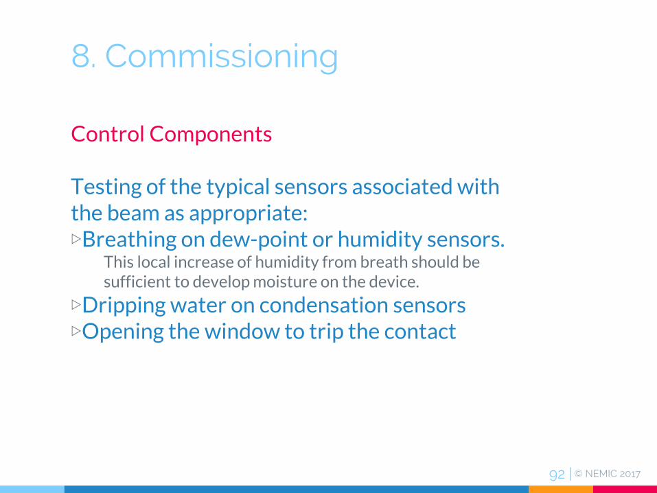
Control Components
Testing of the typical sensors associated with the beam as appropriate:▷Breathing on dew-point or humidity sensors.
This local increase of humidity from breath should be sufficient to develop moisture on the device.
▷Dripping water on condensation sensors▷Opening the window to trip the contact

© NEMIC 201793 |
9. EXAMPLEActive Beams in a Computer Lab

© NEMIC 201794 |
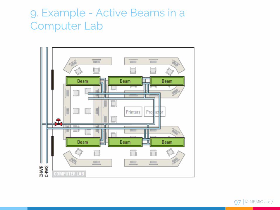
9. Example - Active Beams in a Computer Lab
▷This space is a school computer lab designed for 26 occupants, 26 computers with one LCD monitor each, a projector, three printers, and T8 florescent lighting▷Temperature set-point is 75 °F at 50% RH in the summer▷The room is 50 ft long, 50 ft wide, and has a floor-to-ceiling height of 9 ft. The ceiling is exposed, with possible duct connections in the interior of the space.

© NEMIC 201795 |
9. Example - Active Beams in a Computer Lab
Assumptions▷Infiltration is minimal, and is neglected for the purposes of this example.▷The specific heat and density of the air for this example will be 0.24 Btu/lb°Fand 0.075 lb/ft2 respectively.▷The air handling system utilizes energy recovery to provide 65 °F at 50 °F dew point.

© NEMIC 201796 |
9. Example - Active Beams in a Computer Lab
Total Capacity 33044 Btu/h
Quantity 6
Length 96 in.
Width 24 in.
Airflow 780 cfm
Throw 17 ft.
Air Pressure Drop 0.76 in.
Transfer Efficiency 42.4 Btu/h cfm
Water Flow Rate 6.48 gpm
Water Pressure Drop 4.6 ft hd
NC 30
Selected Active CB Specifications
32902 Btu/h
632 cfm
Supply Air Temperature :65 °F
Required System Performance
© NEMIC 201797 |
9. Example - Active Beams in a Computer Lab


© NEMIC 201799 |
NextANSI/ASHRAE Standard 200-2015, Methods of Testing Chilled Beams