fundamental cases of urban acoustics and their interaction ... · fundamental cases of urban...
TRANSCRIPT
Fundamental Cases of Urban Acoustics and Their
Interaction with Propagating Sound: Phase II
by W. C. Kirkpatrick Alberts, II, Mark A. Coleman, and John M. Noble
ARL-TR-5285 September 2010
Approved for public release; distribution unlimited.
NOTICES
Disclaimers The findings in this report are not to be construed as an official Department of the Army position unless so designated by other authorized documents. Citation of manufacturer’s or trade names does not constitute an official endorsement or approval of the use thereof. Destroy this report when it is no longer needed. Do not return it to the originator.

Army Research Laboratory Adelphi, MD 20783-1197
ARL-TR-5285 September 2010
Fundamental Cases of Urban Acoustics and Their Interaction with Propagating Sound: Phase II
W. C. Kirkpatrick Alberts, II, Mark A. Coleman, and John M. Noble
Computational and Information Sciences Directorate, ARL Approved for public release; distribution unlimited.

ii
REPORT DOCUMENTATION PAGE Form Approved OMB No. 0704-0188
Public reporting burden for this collection of information is estimated to average 1 hour per response, including the time for reviewing instructions, searching existing data sources, gathering and maintaining the data needed, and completing and reviewing the collection information. Send comments regarding this burden estimate or any other aspect of this collection of information, including suggestions for reducing the burden, to Department of Defense, Washington Headquarters Services, Directorate for Information Operations and Reports (0704-0188), 1215 Jefferson Davis Highway, Suite 1204, Arlington, VA 22202-4302. Respondents should be aware that notwithstanding any other provision of law, no person shall be subject to any penalty for failing to comply with a collection of information if it does not display a currently valid OMB control number. PLEASE DO NOT RETURN YOUR FORM TO THE ABOVE ADDRESS.
1. REPORT DATE (DD-MM-YYYY)
September 2010 2. REPORT TYPE
Final 3. DATES COVERED (From - To)
February 2009-November 2009 4. TITLE AND SUBTITLE
Fundamental Cases of Urban Acoustics and Their Interaction with Propagating Sound: Phase II
5a. CONTRACT NUMBER
5b. GRANT NUMBER
5c. PROGRAM ELEMENT NUMBER
6. AUTHOR(S)
W. C. Kirkpatrick Alberts, II, Mark A. Coleman, and John M. Noble 5d. PROJECT NUMBER
5e. TASK NUMBER
5f. WORK UNIT NUMBER
7. PERFORMING ORGANIZATION NAME(S) AND ADDRESS(ES)
U.S. Army Research Laboratory ATTN: RDRL-CIE-S 2800 Powder Mill Road Adelphi, MD 20783-1197
8. PERFORMING ORGANIZATION REPORT NUMBER
ARL-TR-5285
9. SPONSORING/MONITORING AGENCY NAME(S) AND ADDRESS(ES)
10. SPONSOR/MONITOR'S ACRONYM(S)
11. SPONSOR/MONITOR'S REPORT NUMBER(S)
12. DISTRIBUTION/AVAILABILITY STATEMENT
Approved for public release; distribution unlimited.
13. SUPPLEMENTARY NOTES
14. ABSTRACT
An ongoing U.S. Army Research Laboratory (ARL) effort to study fundamental cases of urban acoustics with the goal of enhanced prediction capabilities found that, in Phase I of the study, a single-story isolated building can be adequately described, in some instances, as a wide barrier of finite length. The structure investigated during Phase I was a small, architecturally simple, gabled-roofed building typical of suburban and rural residential housing. To expand upon the first phase, Phase II investigates a large, semi-isolated, multi-faceted building of cinder block construction typical to urban areas. Comparisons between the experimental results of the second phase and the models used in describing the first phase reveal that the interaction of propagating sound with the geometrical complexity of the Phase II structure cannot be successfully described using diffraction models commonly used with sound propagation over barriers.
15. SUBJECT TERMS
Urban acoustics, diffraction
16. SECURITY CLASSIFICATION OF: 17. LIMITATION
OF ABSTRACT
UU
18. NUMBER OF PAGES
22
19a. NAME OF RESPONSIBLE PERSON
W. C. Kirkpatrick Alberts a. REPORT
Unclassified b. ABSTRACT
Unclassified c. THIS PAGE
Unclassified 19b. TELEPHONE NUMBER (Include area code)
(301) 394-2121
Standard Form 298 (Rev. 8/98)
Prescribed by ANSI Std. Z39.18

iii
Contents
List of Figures iv
List of Tables iv
1. Introduction 1
2. Experimental Configuration 1
3. Results and Analysis 5
4. Concluding Remarks 10
5. References 11
Appendix. Source and Sensor Positions 13 Distribution 15

iv
List of Figures
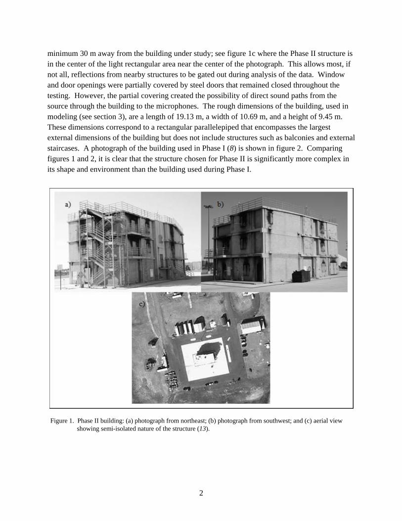
Figure 1. Phase II building: (a) photograph from northeast; (b) photograph from southwest; and (c) aerial view showing semi-isolated nature of the structure (13). ....................................2
Figure 2. Photograph of Phase I building. ......................................................................................3
Figure 3. Wire frame of Phase II building showing microphone positions (red) and source positions (green).........................................................................................................................3
Figure 4. Time traces measured in the shadow zone of the Phase I building (blue) and the Phase II building (green). Each microphone was 5 cm from the façade directly opposite the source. ..................................................................................................................................6
Figure 5. Plot showing measured and calculated spectra for normal incidence on the south façade of the building, SL1S: (a) microphone 9; (b) microphone 10; (c) microphone 11; and (d) microphone 12. In each plot blue line is the measurement, the red line is the BTM model calculation, and the green line is the Pierce model calculation. ............................7
Figure 6. Normalized data compared to standard barrier diffraction models: (a) microphone 14, SL2E; (b) microphone 29, SL2E; and (c) microphone 27, SL1S. Color representation as in figure 5. ......................................................................................................8
List of Tables
Table A-1. Microphone numbers and positions relative to building center at ground level. .......13
Table A-2. Source names and locations relative to building center at ground level. ...................14
1
1. Introduction
Historically, the urban acoustics literature has been predominantly concerned with noise levels in city street canyons, which has led to the creation of many models that adequately describe portions of the urban noise field and can be used to explore methods of noise abatement (1–4). Many of the current models used only treat a two-dimensional slice of the urban environment (5, 6) with good results. An example of a three-dimensional model that does treat sound propagation in an urban area, a linearised Euler model by Heimann, must contend with long computation times (7), as might be expected due to the complexity of urban terrain. While all of these models can effectively predict the noise distribution in an urban area, there is a need for theoretical efforts to produce propagation models for urban areas that can accurately predict the amplitude and phase of a signature as it travels through an urban area. To support this effort, fundamental cases of urban acoustics are being explored (8, 9) in an attempt to characterize the dominant effects that adequately reproduce the sound field when modeling the complex urban environment and, thus, decrease the calculation time of future models. While a great deal of literature deals with highway noise barriers (10, 11) and some on small free-standing walls (12), a gap exists between barriers and street canyons. Single buildings have received little attention. This report presents some of the results of the second phase of an experimental and theoretical effort to characterize fundamental cases of urban acoustics. Phase I of the study focused on monitoring sound propagating around an isolated, single-story, gabled-roofed building of construction typical of North American suburban and rural housing (8). This second phase expands upon the first by studying a three-story, semi-isolated building of construction typical of urban industrial areas, i.e., the building is constructed of cinder blocks and reinforced concrete and has multiple large protruding facets.
Section 2 briefly describes the experimental configuration and procedures used in the second phase of the effort. Section 3 presents a short analysis of selected experimental results and compares the results to common acoustic diffraction models. Section 4 offers some concluding remarks.
2. Experimental Configuration
Figure 1a shows a photograph of the building used during this phase of the study. The photograph was taken from the northeast to best show the complicated structure of the north and east façades. The south and west façades are shown in figure 1b. The building was three stories high and constructed from concrete slabs and cinder blocks. Here, the building is defined as semi-isolated, which means that other buildings or other vertical reflecting surfaces are at
2
minimum 30 m away from the building under study; see figure 1c where the Phase II structure is in the center of the light rectangular area near the center of the photograph. This allows most, if not all, reflections from nearby structures to be gated out during analysis of the data. Window and door openings were partially covered by steel doors that remained closed throughout the testing. However, the partial covering created the possibility of direct sound paths from the source through the building to the microphones. The rough dimensions of the building, used in modeling (see section 3), are a length of 19.13 m, a width of 10.69 m, and a height of 9.45 m. These dimensions correspond to a rectangular parallelepiped that encompasses the largest external dimensions of the building but does not include structures such as balconies and external staircases. A photograph of the building used in Phase I (8) is shown in figure 2. Comparing figures 1 and 2, it is clear that the structure chosen for Phase II is significantly more complex in its shape and environment than the building used during Phase I.
Figure 1. Phase II building: (a) photograph from northeast; (b) photograph from southwest; and (c) aerial view showing semi-isolated nature of the structure (13).

3
Figure 2. Photograph of Phase I building.
Table A-1, in appendix A, gives the positions of the microphones relative to an origin placed in the center of the building at ground level. Table A-1 also numbers each of the microphones for easy reference in later discussion of results. Figure 3, shows a wire frame, with dimensions listed above, of the building with microphone positions marked by red points and source positions by green points. Source positions are also marked with their position designations.
Figure 3. Wire frame of Phase II building showing microphone positions (red) and source positions (green).
The experimental configuration used in this phase of the work was very similar to the configuration used in Phase I in that the microphones were placed near the ground at each façade of the building and on the roof. Near-ground microphones (three per façade) during the Phase I experiment were linearly arrayed perpendicular to each façade and parallel to the ground.
SL1S
SL2E
SL1E
SL2S

4
Another linear array of three microphones projected vertically from the center of the ridge of the roof, figure 2. In Phase I, a sixteenth microphone between the building and the source was used as a reference. Temperature and wind sensors were co-located with the near-ground linear arrays. This configuration allowed the sound field to be sufficiently sampled as the sound interacted with the building (8). The Phase II building, being a much larger and more complex structure than that of Phase I, required that the complexity of the experimental configuration be increased to sufficiently instrument the structure.
While the Phase I site could be sufficiently instrumented with 16 sensors, it was deemed necessary to double the number of sensors for Phase II. These 32 sensors were placed in a fashion similar to that described above. Near the ground, at each façade, three microphones were linearly arrayed at 5 cm, 1.05 m, and 2.05 m from the wall and at heights listed in table A-1. A fourth microphone at each façade was placed approximately 1 to 1.7 m beyond the 2.05 m microphone. The four microphones at each façade were arrayed, as above, perpendicular to the wall. A temperature probe and an ultrasonic anemometer were placed below and above, respectively, the microphone at 1.05 m. The near-ground microphones were numbered such that the lowest number in a set of four was closest to the wall. Microphones 1−4 were at the south façade, 5−8 were at the east façade, 9−12 were at the north façade, and 13−16 were at the west façade, figure 3 and table A-1.
The remaining 16 microphones were placed at various positions around the roof and around the upper portion of each façade. As with the near-ground microphones, each façade had a set of four microphones. In this instance, however, two microphones were placed approximately 2/3 up the height of each façade and two microphones were placed on the roof. The microphones mounted up the wall (17, 18, 21, 22, 25, 26, 29, and 30) were mounted in a linear array perpendicular to the wall and separated from the wall by 75 cm and 1.5 m. with the lowest numbered microphones closest to the wall. Of the remaining eight microphones on the roof (19, 20, 23, 24, 27, 28, 31, and 32), four were at each façade edge and four were inset from the edges, with the lower number near the edge. Thus, microphones 17–20 were at the south façade, 21–24 at the east façade, 25–28 at the north façade, and 29–32 at the west façade. All microphone signals were band pass filtered from 25 Hz to 3.8 kHz.
Two sources were used during testing. These were a propane cannon and a loudspeaker broadcasting random noise that was band limited from 0 to 4 kHz with a 5 Hz frequency resolution. Each source was placed in four positions: normal to the south façade; 22.5° incidence to the south façade; 22.5° incidence to the east façade; normal to the east façade, figure 3. Table A-2 lists the coordinates, relative to the same origin as the microphones, and the name of each source position. The height column in table A-2 lists the height of the propane cannon muzzle and the height to the center of the loudspeaker separated by a slash.

5
3. Results and Analysis
Because the building used in Phase II of the study is semi-isolated and is larger and more structured than the building used during Phase I (compare figures 1 and 2), the acoustic signatures collected around the Phase II site are expected to exhibit increased complexity over similar signatures collected around the Phase I site. This is apparent in figure 4, which shows a time trace from each experiment using the propane cannon as the source. The microphone, during each experiment, was placed 5 cm from the façade on the side of the building in the acoustic shadow. In figure 4, the source was normal to the wall opposite the microphone. Each time trace in figure 4 has been normalized by its own maximum value and each trace has been artificially offset from zero to avoid confusion. The assumed start of the first diffracted arrival in each time trace has been marked in the figure. If the traces are compared, it is clear that the Phase II trace is more complex than the Phase I trace. It is of note that the highest amplitude arrival in the Phase II trace occurs well after the first significant increase above the background (indicated by bracket in the figure). This bracketed portion of the trace is assumed to be transmission through the building because window and door openings, as mentioned in the previous section, were not completely covered (i.e., roughly 5 cm gaps below doors). This assumption is further supported by the shorter path lengths through, rather than around, the building and the reduced amplitude that might be expected due to a smaller percentage of sound entering the building. Reflections and diffractions within the structure also have an effect on the sound coming through the building. Based upon calculated path lengths, the late arrivals, at approximately 0.25 s, in the Phase II trace are reflections from the structures surrounding the building under study, figure 1c. These reflections are time-windowed out during subsequent analysis.

6
Figure 4. Time traces measured in the shadow zone of the Phase I building (blue) and the Phase II building (green). Each microphone was 5 cm from the façade directly opposite the source.
Analysis of the Phase I data showed that, in cases of near-normal incidence, the sound propagated behind the building could be reasonably described by diffraction models commonly used with sound propagation over highway noise barriers (8, 9). The models used during the Phase I analysis were the Pierce model and the Biot-Tolstoy-Medwin (BTM) model. The Pierce model calculates the pressure diffracted behind barriers in the frequency domain and is able to be easily modified to include atmospheric absorption and the effects of ground reflections. The BTM model is a time domain diffraction calculation based upon the Huygens principle. In the BTM model, a propagating impulse, upon encountering an edge, generates an infinite number of secondary sources distributed evenly along the edge. The outputs of these secondary sources are then summed to calculate the pressure at a receiver. The procedure is repeated on subsequent diffracting edges. Both models, having been designed for use in predicting the sound pressure behind a barrier of finite width, are capable, without any modification, of accurately predicting the pressure diffracted beyond a maximum of two edges. Since both models were used unaltered with respect to the number of diffracting edges, features of a building beyond roof edges and corners are neglected in the analysis, e.g., in Phase I, the gabled entry of the building (figure 2) and diffraction over the eave closest to the source were neglected. In Phase II, all of the external structure of the façades, the external staircase, and the rubbish container (figure 1a and 1b) were neglected because neither model, in its unaltered form, is capable of handling the multiple diffractions caused by the façade structure of the Phase II building.
Phase I
Phase II start
reflection
through building
diffracted arrivals
7
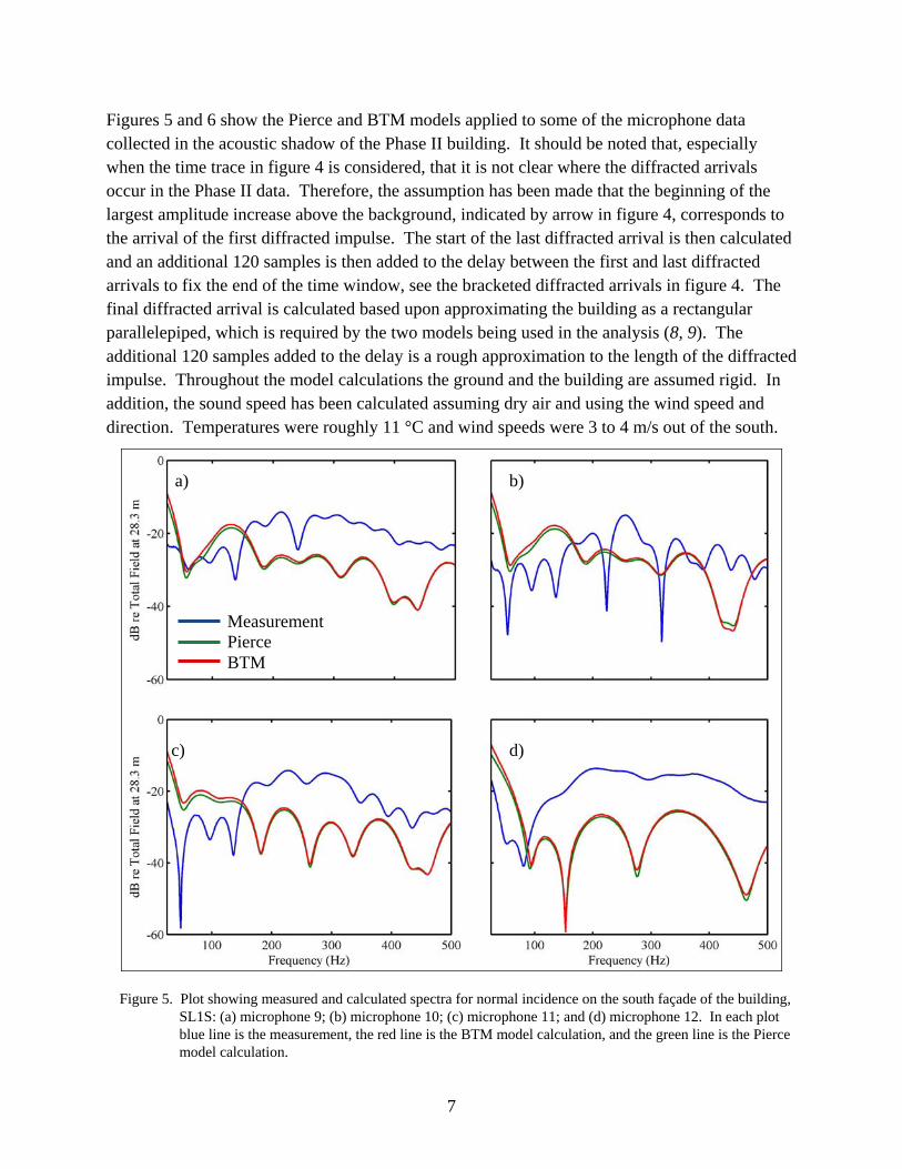
Figures 5 and 6 show the Pierce and BTM models applied to some of the microphone data collected in the acoustic shadow of the Phase II building. It should be noted that, especially when the time trace in figure 4 is considered, that it is not clear where the diffracted arrivals occur in the Phase II data. Therefore, the assumption has been made that the beginning of the largest amplitude increase above the background, indicated by arrow in figure 4, corresponds to the arrival of the first diffracted impulse. The start of the last diffracted arrival is then calculated and an additional 120 samples is then added to the delay between the first and last diffracted arrivals to fix the end of the time window, see the bracketed diffracted arrivals in figure 4. The final diffracted arrival is calculated based upon approximating the building as a rectangular parallelepiped, which is required by the two models being used in the analysis (8, 9). The additional 120 samples added to the delay is a rough approximation to the length of the diffracted impulse. Throughout the model calculations the ground and the building are assumed rigid. In addition, the sound speed has been calculated assuming dry air and using the wind speed and direction. Temperatures were roughly 11 °C and wind speeds were 3 to 4 m/s out of the south.
Figure 5. Plot showing measured and calculated spectra for normal incidence on the south façade of the building, SL1S: (a) microphone 9; (b) microphone 10; (c) microphone 11; and (d) microphone 12. In each plot blue line is the measurement, the red line is the BTM model calculation, and the green line is the Pierce model calculation.
a)
d)
b)
c)
Measurement Pierce BTM
8
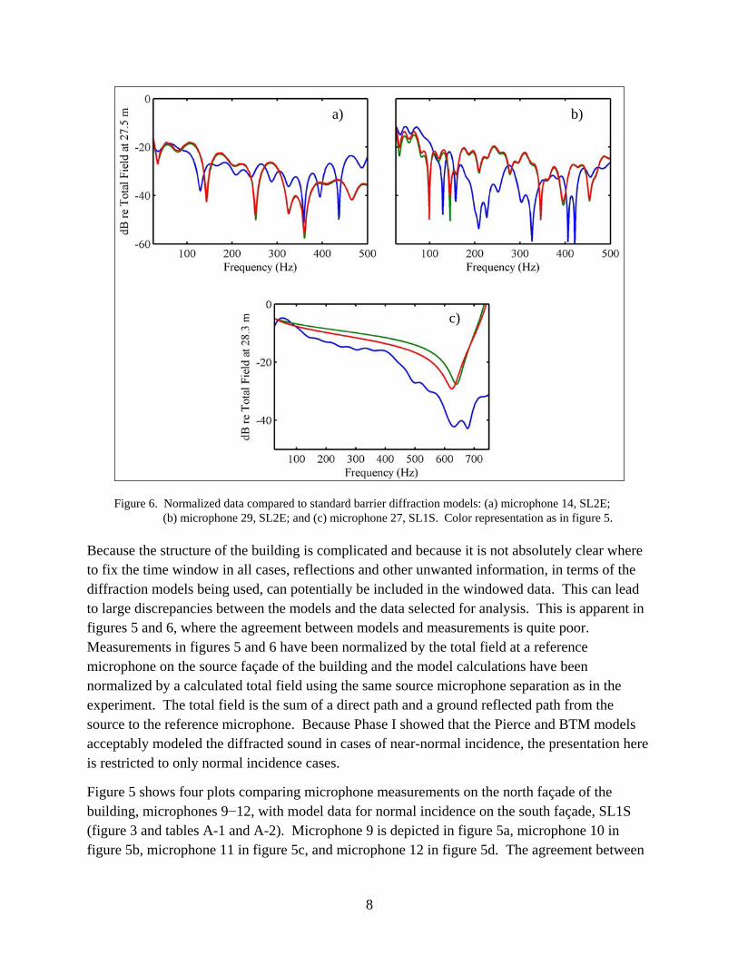
Figure 6. Normalized data compared to standard barrier diffraction models: (a) microphone 14, SL2E; (b) microphone 29, SL2E; and (c) microphone 27, SL1S. Color representation as in figure 5.
Because the structure of the building is complicated and because it is not absolutely clear where to fix the time window in all cases, reflections and other unwanted information, in terms of the diffraction models being used, can potentially be included in the windowed data. This can lead to large discrepancies between the models and the data selected for analysis. This is apparent in figures 5 and 6, where the agreement between models and measurements is quite poor. Measurements in figures 5 and 6 have been normalized by the total field at a reference microphone on the source façade of the building and the model calculations have been normalized by a calculated total field using the same source microphone separation as in the experiment. The total field is the sum of a direct path and a ground reflected path from the source to the reference microphone. Because Phase I showed that the Pierce and BTM models acceptably modeled the diffracted sound in cases of near-normal incidence, the presentation here is restricted to only normal incidence cases.
Figure 5 shows four plots comparing microphone measurements on the north façade of the building, microphones 9−12, with model data for normal incidence on the south façade, SL1S (figure 3 and tables A-1 and A-2). Microphone 9 is depicted in figure 5a, microphone 10 in figure 5b, microphone 11 in figure 5c, and microphone 12 in figure 5d. The agreement between
a) b)
c)

9
model and measurement throughout figure 5 is poor. However, close inspection does show areas in each plot where certain features are observed in both model calculations and measurement. With the exception of figure 5d, the model calculations tend to accurately reproduce, in frequency, the minimum near 50 Hz in each plot. This might be anticipated since 50 Hz is less likely to be affected by the smaller scale structure of the building. It should also be noted that, especially in figure 5a and 5b, the agreement between the models and the measurements rapidly degrades as the frequency increases. This degradation can be attributed to a combination of windowing errors, corruption of the windowed data by sound passing through the building, and proximity of the microphone to the building. Especially in the case of microphone 9 (5 cm from the façade, figure 5a), the sound diffracted around the northeast corner of the building will interact with the smaller structures between the corner and the microphone, figure 1a. Microphone 10, figure 5b, was 1.05 m from the façade and, thus, we might expect the agreement between the model and the measurement to improve. No improvement is observed until figure 5c is examined. In figure 5c, the models do not accurately reproduce the magnitude of the curve but they do tend to reproduce the frequency positions of some of the minima in the measurement implying that the smaller structures on the building have less of an effect on the propagating sound. However, in figure 5d, the measurement at microphone 12, 3 m from the building, does not agree with the models at all. This microphone, while it was 3 m away from the façade, was also more than a meter below the other microphones due to the geometry of the stairway on which microphone 12 rested, figure 1a. The observed spectrum in figure 5d is likely due to a different set of diffracting edges from those that influenced the spectra in
Figure 6 shows three more examples of normal incidence data compared to the Pierce and BTM models. Figure 6a and 6b depict spectra measured at microphones 14 and 29, respectively, due to normal incidence on the east façade of the building during SL2E. As in figure 5, the models tend to reproduce the measurements at the lowest frequencies, presumably due to reasons similar to the above. Further, paths around the north façade of the building pass at least six vertical edges, each one of which contributes to the diffracted pressure to create the complex structure of the measured curves. Figure 6c shows the spectrum due to normal incidence on the south façade, SL1S, as measured by microphone 27 positioned above the north edge of the roof. The positioning of microphone 27 forces the pressure received by the microphone to be diffracted by only the south edge of the roof (during SL1S and SL2S). In this case, the interference minimum at approximately 625 Hz is predicted well in frequency, but the models do not predict the overall level of the measured curve.

10
4. Concluding Remarks
Acoustic impulse propagation in the vicinity of a large semi-isolated building demonstrates an expected increase in complexity over similar measurements conducted around a small isolated building. Diffraction is the dominant process in both experiments, however, measured data in the acoustic shadow of the large building show features likely due to the surrounding environment, to small scale facets of the façades, and to open paths through the interior of the building. Models that showed limited success in reproducing measured spectra in the acoustic shadow of a small, isolated building fail to reproduce all but the lowest frequency information in the measured spectra in the shadow of a large semi-isolated building of increased architectural complexity. Higher frequencies agree poorly with the measured data presumably due to the significant number of diffracting edges and reflecting surfaces present on the façades of the building. The implication of the poor model performance is that the models used should be heavily modified or abandoned in favor of a more comprehensive calculation.

11
5. References
1. Kang, J. Numerical Modeling of the Sound Fields in Urban Squares. J. Acoust. Soc. Am. 2005, 117 (6), 3695–3706.
2. Iu, K. K.; Li, K. M. The Propagation of Sound in Narrow Street Canyons. J. Acoust. Soc. Am. 2002, 112 (2), 537–550.
3. Le Pollès, T.; Picaut, J.; Bérengier, M. Sound Field Modeling in a Street Canyon with Partially Diffusely Reflecting Boundaries by the Transport Theory. J. Acoust. Soc. Am. 2004, 116 (5), 2969–2983.
4. Li, K. M.; Lai, C.Y.C. A Note on Noise Propagation in Street Canyons. J. Acoust. Soc. Am. 2009, 126 (2), 644–655.
5. Hornikx, M.; Forssén, J. Noise Abatement Schemes for Shielded Canyons. App. Acoust. 2009, 70, 267-273.
6. Albert, D. G.; Liu, L. B.; Moran, M. L. Time Reversal Processing for Source Location in an Urban Environment. J. Acoust. Soc. Am. 2005, 118 (2), 616–619.
7. Heimann, D. Three-dimensional Linearised Euler Model Simulations of Sound Propagation in Idealized Urban Situations with Wind Effects. App. Acoust. 2007, 68, 217–237.
8. Alberts, II, W.C.K.; Noble, J. M.; Coleman, M. A. Sound Propagation in the Vicinity of an Isolated Building: An Experimental Investigation. J. Acoust. Soc. Am. 2008, 124 (2), 733–742.
9. Alberts, II, W.C.K.; Noble, J. M.; Coleman, M. A. On the Application of Well-known Diffraction Models to the Sound Field in the Shadow Zone of an Isolated Building. App. Acoust. 2009, 70, 1128–1130.
10. Wadsworth, G. J.; Chambers, J. P. Scale Model Experiments on the Insertion Loss of Wide and Double Barriers. J. Acoust. Soc. Am. 2000, 107 (5), 2344–2350.
11. Pierce, A. D. Diffraction of sound Around Corners and Over Wide Barriers. J. Acoust. Soc. Am. 1974, 55 (5), 941–955.
12. Liu, L.; Albert, D. G. Acoustic Pulse Propagation Near a Right-angle Wall. J. Acoust. Soc. Am. 2006, 119 (4), 2073–2083.
13. Aerial view obtained from Google maps.

12
INTENTIONALLY LEFT BLANK.

13
Appendix. Source and Sensor Positions
Contained in this appendix are tables listing the microphone (Table A-1) and source (Table A-2) positions during the experiment. All coordinates are relative to the center of the building at ground level. Distances listed in Table A-1 are relative to the closest building surface (wall or roof).
Table A-1. Microphone numbers and positions relative to building center at ground level.
Microphone Number x (m) y (m) z (m) Distance from Building (m)
1 5.04 -0.36 1.3 0.05 2 6.05 -0.36 1.36 1.05 3 7.05 -0.36 1.39 2.05 4 8.70 -0.36 1 3.71 5 2.33 9.61 1.31 0.05 6 2.33 10.61 1.35 1.05 7 2.33 11.61 1.37 2.05 8 2.33 12.84 1 3.28 9 -5.09 -0.26 3.22 0.05
10 -6.09 -0.26 3.27 1.05 11 -7.09 -0.26 3.33 2.05 12 -8.04 -0.26 1.9 3 13 0.10 -9.30 1.32 0.05 14 0.10 -10.30 1.36 1.05 15 0.10 -11.30 1.54 2.05 16 0.10 -12.68 1 3.43 17 6.10 3.74 7.58 0.75 18 6.85 3.74 7.58 1.5 19 4.82 0.16 10.78 1.33 20 1.90 0.16 9.65 0.2 21 2.20 10.31 7.48 0.75 22 2.20 11.06 7.48 1.5 23 2.67 9.09 10.58 1.13 24 1.74 6.43 9.65 0.2 25 -5.79 -0.30 6.09 0.75 26 -6.54 -0.30 6.09 1.5 27 -4.31 -0.51 10.77 1.31 28 -2.31 1.25 9.66 0.2 29 2.00 -10.31 7.87 0.75 30 2.00 -11.06 7.87 1.5 31 0.41 -8.88 10.24 1.25 32 0.41 -6.13 9.48 0.2

14
Table A-2. Source names and locations relative to building center at ground level.
Source Name x (m) y (m) z (m)–Propane Cannon/Speaker SL1S 34.1 1.2 0.42 / 1.11 SL2S 32.01 11.7 0.42 / 1.01 SL1E 11.37 35.54 0.42 / 1.01 SL2E 0.875 37.63 0.42 / 1.01
15
No. of Copies Organization 1 ADMNSTR ELEC DEFNS TECHL INFO CTR ATTN DTIC OCP 8725 JOHN J KINGMAN RD STE 0944 FT BELVOIR VA 22060-6218 1 CD OFC OF THE SECY OF DEFNS ATTN ODDRE (R&AT) THE PENTAGON WASHINGTON DC 20301-3080 1 US ARMY RSRCH DEV AND ENGRG CMND ARMAMENT RSRCH DEV & ENGRG CTR ARMAMENT ENGRG & TECHNLGY CTR ATTN AMSRD AAR AEF T J MATTS BLDG 305 ABERDEEN PROVING GROUND MD 21005-5001 1 PM TIMS, PROFILER (MMS-P) AN/TMQ 52 ATTN B GRIFFIES BUILDING 563 FT MONMOUTH NJ 07703 1 US ARMY INFO SYS ENGRG CMND ATTN AMSEL IE TD A RIVERA FT HUACHUCA AZ 85613-5300 1 COMMANDER US ARMY RDECOM ATTN AMSRD AMR W C MCCORKLE 5400 FOWLER RD REDSTONE ARSENAL AL 35898-5000 1 US GOVERNMENT PRINT OFF DEPOSITORY RECEIVING SECTION ATTN MAIL STOP IDAD J TATE 732 NORTH CAPITOL ST NW WASHINGTON DC 20402 1 US ARMY RSRCH LAB ATTN RDRL CIM G T LANDFRIED BLDG 4600 ABERDEEN PROVING GROUND MD 21005-5066
No. of Copies Organization 1 DIRECTOR US ARMY RSRCH LAB ATTN RDRL ROE V W D BACH PO BOX 12211 RESEARCH TRIANGLE PARK NC 27709 6 US ARMY RSRCH LAB ATTN IMNE ALC HRR MAIL & RECORDS MGMT ATTN RDRL CIE S J M NOBLE ATTN RDRL CIE S M COLEMAN ATTN RDRL CIE S W ALBERTS II ATTN RDRL CIM L TECHL LIB ATTN RDRL CIM P TECHL PUB ADELPHI MD 20783-1197 TOTAL: 15 (1 ELEC, 1 CD, 13 HCs)
16
INTENTIONALLY LEFT BLANK.