functional safety sil - jumo
TRANSCRIPT


Functional Safety SILSafety Integrity LevelDr. Thomas ReusMatthias Garbsch
NoteThis reference work has been created to the best knowledge and belief. We assume no liability forpossible errors. The definitive source of informtion is always the operating manual for the relevantdevice.

PrefaceWho should read thisThis booklet is intended as an introductory aid to functional safety (chapter 4 “Glossary”, page 15).It is aimed at JUMO customers and staff, and its content is limited to the areas and applications whereJUMO products are used.Why JUMO offers SIL productsJUMO develops and manufactures, amongst other items, products according to the Pressure Equip-ment Directive, the Machinery Directive, the ATEX Directive and special safety engineering productstandards, such as DIN 3440.DIN EN 61508 is nowadays indispensible for those products that are designed for safety applicati-ons, since it defines the “state of the art” for functional safety.Summary of products with SIL capabilityFor an up-to-date overview and detailed information on our SIL-certified products, visit: www.jumo.de Products Approvals SIL.TerminologyThis booklet makes frequent reference to (DIN) EN 61508. The full title of this standard is “FunctionalSafety of Safety-Related E/E/PE Systems”. Its content is identical to the IEC 61508 internationalstandard.
Dr. Thomas Reus Matthias Garbsch
JUMO GmbH & Co. KGMoritz-Juchheim-Straße 136039 Fulda, GermanyPhone: +49 661 6003-0Fax: +49 661 6003-607Email: [email protected]
[email protected]: www.jumo.net
Reprinting permitted with source citation! Part No.: 00476107Book No.: FAS630Edition: April 2016ISBN: 978-3-935742-18-4

Contents
1 Legal foundations, significance of standards ............................... 51.1 Motivation for standards ........................................................................................ 51.2 Functional safety standards – development of (DIN) EN 61508 ........................... 51.3 Legal position of (DIN) EN 61508 in the sense of an EU directive ....................... 62 Fundamental principle of (DIN) EN 61508 ...................................... 72.1 Changes compared with previous safety standards ............................................. 72.2 Risk reduction ....................................................................................................... 72.3 Tolerable risk ......................................................................................................... 92.4 Life cycle ............................................................................................................. 102.5 JUMO’s task during the safety life cycle ............................................................. 10
3 Terms used in (DIN) EN 61508 ....................................................... 113.1 Safety integrity and its measurement
– the Safety Integrity Level (SIL) ......................................................................... 113.2 PFD, PFH: operating modes and failure probabilities ......................................... 113.3 HFT, SFF: Safety integrity of the hardware ......................................................... 123.4 Lifetime and proof-test interval ............................................................................ 143.5 Failure rate .......................................................................................................... 14
4 Glossary .......................................................................................... 15
Functional Safety SIL

Contents
Functional Safety SIL

1 Legal foundations, significance of standards
1.1 Motivation for standardsOur everyday life is governed by machinery and equipment to which we blindly entrust our lives, e.g.automobiles, traffic lights, medical equipment and energy installations.For this reason, the legislature has established laws and other legal regulations that define specificrequirements in safety matters.In Germany, for instance, the statutory trade insurance associations (“Berufsgenossenschaften”) setup accident prevention regulations and monitor their implementation. Throughout the European Uni-on, EU Directives define requirements for systems and their operators, to protect and preservehealth and the quality of the environment. They prescribe specific product characteristics for thepreservation of consumer health and safety.
In Germany, the compliance with standards and the required safety targets is enforced through theLaw on Equipment and Product Safety, in conjunction with the rights to damages prescribed by§ 823 of the German Civil Code (“Bürgerliches Gesetzbuch”). Not only equipment manufacturers,such as JUMO, but also the system and plant operators, are therefore obliged to achieve the corre-sponding safety targets.Similar regulations apply in other countries.
It is necessary here to distinguish between safe products in the generalized sense, and productsthat are specially designed for safety applications. For the latter, (DIN) EN 61508 has now becomeindispensable, since it defines the “state of the art” for functional safety.
1.2 Functional safety standards – development of (DIN) EN 61508The key event was the poison gas accident in the northern Italian town of Seveso in July 1976. Since then, the European Union Directive 96/82/EU has defined the legal conditions for plants witha high hazard potential.
The German implementation of the directive 96/82/EU is realized in the hazardous incident regula-tions of the Federal Law on Emission Safety (12. BImSchV).
Up to 31 July 2004, the hazardous incident regulations referred to the German StandardsDIN V 19250 and DIN V 19251, in which the requirements were defined in Classes AK 1 to 8.
Since 2002, (DIN) EN 61508 provides a new method for risk assessment and the required proof ofeffectiveness for safety-related systems, in order to continue to fulfil the aims of the hazardous inci-dent regulations. This defines four safety levels: SIL1 to SIL4.(DIN) EN 61508 has thus replaced the German standards DIN V 19250 and DIN V 19251.
Ratification of the series of standards took place in July 2001. The standard was thereupon accep-ted by the European standards organization CENELEC. On 1 August 2002 it was incorporated intothe German set of standards as (DIN) EN 61508 (VDE 0803), and thus defines the state of the artfor E/E/PE (electrical, electronic and programmable electronic) systems that are involved in safetyfunctions for safety-critical applications.
(DIN) EN 61508 is a generic standard, i. e. independent of the application. It is a fundamental stan-dard and therefore generally valid for all E/E/PE systems.
(DIN) EN 61508 is based on the international standard IEC 61508, and thus has worldwide validity.It is the first international harmonized set of regulations that is application-independent for all E/E/PE systems.
The application-specific standards are now being derived from this, one-by-one, such as:
• (DIN) EN 61511 for functional safety in process engineering,• (DIN) EN 62061 for functional safety in machine controls.
1 Legal foundations, significance of standards 5JUMO, FAS 630, edition 2016-04-20

1 Legal foundations, significance of standards
1.3 Legal position of (DIN) EN 61508 in the sense of an EU directive(DIN) EN 61508 describes the state of the art with regard to functional safety. But it is not harmonized as part of an EU directive, i.e. there is no automatic assumption of fulfill-ment of the protective aims of a directive associated with this standard. At present, compliance is therefore voluntary and not binding in the sense of the EU directives.
Nevertheless, the manufacturer of a safety-engineering product can apply (DIN) EN 61508 in fulfill-ment of basic requirements according to European directives. This results from the new concept of the standard, e.g. in the following cases:
Explanation:For the process industry, (DIN) EN 61511 has already been derived from (DIN) EN 61508 as a basicstandard. Likewise, (DIN) EN 62061 is available for the Machinery Directive. For combustion en-gineering, (DIN) EN 50156 is available as a standard.
The further development of standardization methodology was made necessary by the ever-increa-sing complexity of modern safety-critical systems. Up to the mid-90s, one could say: the applicati-on of microelectronics or microcomputers in safety engineering was inconceivable or only feasiblewith extremely involved test equipment. At that time, many standards and regulations still expres-sly demanded conventional solutions with interlocks implemented by relays or contactors. The ap-plication of equipment that was more modern, more economic, and often even superior from thesafety engineering aspect, was not permitted. But the requirements that a system has to fulfill are becoming ever more complex, and can, as arule, only be economically met by electronic solutions.This is especially so in the sector of digital computers and automation technology, where complexdigital circuits are used for the central unit.
From a harmonized European standard (such as (DIN) EN 954 and (DIN) EN 60204-1, that harmo-nize the Machinery Directive) there is a referral to (DIN) EN 61508. This ensures that the relevantrequirements of the standard are fulfilled (“jointly applicable standard”). If a manufacturer applies (DIN) EN 61508 in the sense of this referral, in an expert and responsiblemanner, then he is making use of the assumption of fulfillment from the referring standard.There is no harmonized standard (such as, for example, DIN 3440, DIN EN 14597) for the applica-tion concerned. In this case, the manufacturer may apply (DIN) EN 61508 (state of the art). But the-re is no assumption of fulfillment.
6 1 Legal foundations, significance of standards JUMO, FAS 630, edition 2016-04-20

2 Fundamental principle of (DIN) EN 61508
2.1 Changes compared with previous safety standardsIn the (DIN) EN 61508 standard for functional safety, the requirements for safety-related systemsare divided into Safety Integrity Levels (SIL) (see Glossary). Instruments, sensors and controls musttherefore have a SIL classification according to the standard. A new understanding of safety alsoarises. Whereas previous safety engineering standards usually involved a purely qualitative exami-nation, the new standard demands, for the first time, a quantitative examination of the entire systemand proof that the residual risk is sufficiently small.Furthermore, the entire safety life cycle of a system is also regulated for the first time, see chapter2.4 „Life cycle“, page 10.
2.2 Risk reductionEvery application of technology represents a simultaneous safety engineering risk. The more peop-le, property, or the environment are set at risk, the more measures must be taken to reduce that risk.The risk should at least be so far reduced that the probability of a person losing their life as a resultof the failure of a technical device is less than 10-4 fatalities / per person and year.This is roughly equivalent to the risk of a person losing their life as a result of natural causes in thecourse of a year. This risk varies with the age of the person concerned, and lies between 10-2 and10-4. A summary of basic everyday risks is shown in figure 1 on page 8.
In order to achieve functional safety for a machine or plant, it is necessary to ensure that the safety-relevant parts of the control and protection equipment function correctly and, in the event of a fault,respond in such a manner that the system remains safe or is put into a safe state.
The object of (DIN) EN 61508 is to avoid faults in safety-related systems, or to have faults undercontrol and to limit the probability of dangerous failures (risk) in a defined manner. A quantitive proofis required for the residual risk that remains.
2 Fundamental principle of (DIN) EN 61508 7JUMO, FAS 630, edition 2016-04-20

2 Fundamental principle of (DIN) EN 61508
Figure 1: Summary of basic risks
8 2 Fundamental principle of (DIN) EN 61508 JUMO, FAS 630, edition 2016-04-20

2 Fundamental principle of (DIN) EN 61508
2.3 Tolerable riskThe tolerable risk for a technology is not always clearly defined, but is basically determined by so-ciety, taking social and political factors into consideration. If the risk attached to a technical installation is perceived to be too high, then special measures mustbe implemented to reduce the risk.The necessary risk reduction is achieved by a combination of all the safety-relevant protective mea-sures. The residual risk should be, at most, no larger than the tolerable risk.In the end, the plant operator must accept and bear the residual risk.Figure 2: Risk reduction: general concepts
2 Fundamental principle of (DIN) EN 61508 9JUMO, FAS 630, edition 2016-04-20

2 Fundamental principle of (DIN) EN 61508
2.4 Life cycleThe operator of a safety engineering installation has to take suitable steps to assess and reduce riskduring the complete life cycle of the installation. To this end, the (DIN) EN 61508 standard prescri-bes the following steps:An overview of the systematic procedure is represented in figure 3. The first step is to carry out afailure analysis. This is followed by the selection of the measures for keeping faults under controland the implementation of these measures.
Figure 3: Procedure for implementing (DIN) EN 61508
2.5 JUMO’s task during the safety life cycleThe operator of a safety-related installation requires a quantity of technical data and informationabout all the equipment used, in order to be able to carry out the risk assessment for the entire safe-ty loop and over the entire operating life of the system.
So it is naturally advantageous for the operator of the installation to be able to make use of SIL-cer-tified equipment. In this case, the manufacturer, e. g. JUMO, has already established the necessarydata for the instrument concerned, by means of a detailed hazard and risk analysis. All the relevantdata and information for the customer is then presented in a safety manual. The terms that are usedthere are explained in the next chapter.
Risk definition and evaluation according to detailed failure probabilities - for the entire safety circuit(loop) from the point of measurement through the control system to the actuator, as well as duringthe entire life cycle (Overall Safety Life Cycle) of the application.This can be done, for example, by FMEDA (Failure Mode, Effect and Diagnostics Analysis) or Ha-zard Analysis.Determination and implementation of the measures (Management of Functional Safety) for reducingthe residual risk.Use of suitable (certified) equipment.Periodic checking that regulations are correctly observed.
10 2 Fundamental principle of (DIN) EN 61508 JUMO, FAS 630, edition 2016-04-20

3 Terms used in (DIN) EN 61508
3.1 Safety integrity and its measurement– the Safety Integrity Level (SIL)The Safety Integrity Level (safety-related reliability) of a system is “The probability that a safety-re-lated system will perform the required safety function under all defined conditions within a definedtime period according to specification.”
The Safety Integrity Level (SIL) is the measure for safety integrity. It is divided into four discrete le-vels, whereby Safety Integrity Level 4 represents the highest level of safety integrity, and Safety In-tegrity Level 1 represents the lowest level.
The achievable SIL is determined by the following parameters:
• the probability of the hazardous failure of a safety function (PFD or PFH),
• the hardware fault tolerance (HFT),
• the safe failure fraction (SFF),
• the type of components (Type A or Type B),
• lifetime, and
• proof-test.
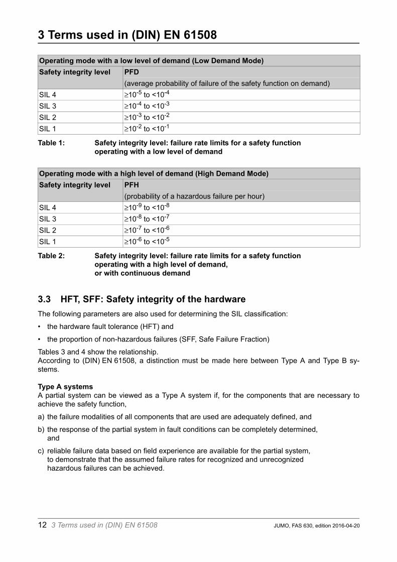
3.2 PFD, PFH: operating modes and failure probabilitiesA distinction is made between two modes of operation for the SIL classification: Low Demand Modeand High Demand Mode.
Low Demand ModeFor operation in Low Demand Mode, it is assumed that the safety function only has to respond oncea year, on average. In this case, the SIL value is derived from the PFD (Probability of Failure on De-mand).PFD is a measure of the probability of failure of the safety function on demand, in a system opera-ting with a low level of demand.
The Low Demand Mode is typically found in process industry installations and plant. Here there are,for instance, emergency shutdown systems that only become active if the normal process goes outof control.
High Demand ModeFor operation in High Demand Mode, it is assumed that the safety function has to respond conti-nuously, or on average once per hour.For a high or continuous rate of demand, the measure that is used is PFH (Probability of Failure perHour), which expresses the probability that there will be a failure of the safety function within a onehour period.
The High Demand Mode is typically found in production installations, where continuous monitoringof the manufacturing operations is necessary.
3 Terms used in (DIN) EN 61508 11JUMO, FAS 630, edition 2016-04-20
3 Terms used in (DIN) EN 61508
Table 1: Safety integrity level: failure rate limits for a safety function operating with a low level of demand
Table 2: Safety integrity level: failure rate limits for a safety functionoperating with a high level of demand, or with continuous demand
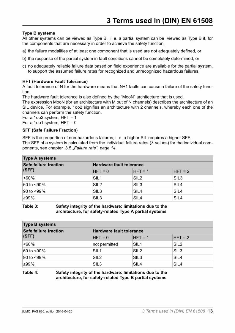
3.3 HFT, SFF: Safety integrity of the hardwareThe following parameters are also used for determining the SIL classification:
• the hardware fault tolerance (HFT) and
• the proportion of non-hazardous failures (SFF, Safe Failure Fraction)
Tables 3 and 4 show the relationship.According to (DIN) EN 61508, a distinction must be made here between Type A and Type B sy-stems.
Type A systemsA partial system can be viewed as a Type A system if, for the components that are necessary toachieve the safety function,
a) the failure modalities of all components that are used are adequately defined, and
b) the response of the partial system in fault conditions can be completely determined, and
c) reliable failure data based on field experience are available for the partial system, to demonstrate that the assumed failure rates for recognized and unrecognized hazardous failures can be achieved.
Operating mode with a low level of demand (Low Demand Mode)Safety integrity level PFD
(average probability of failure of the safety function on demand)SIL 4 10-5 to <10-4
SIL 3 10-4 to <10-3
SIL 2 10-3 to <10-2
SIL 1 10-2 to <10-1
Operating mode with a high level of demand (High Demand Mode)Safety integrity level PFH
(probability of a hazardous failure per hour)SIL 4 10-9 to <10-8
SIL 3 10-8 to <10-7
SIL 2 10-7 to <10-6
SIL 1 10-6 to <10-5
12 3 Terms used in (DIN) EN 61508 JUMO, FAS 630, edition 2016-04-20
3 Terms used in (DIN) EN 61508
Type B systemsAll other systems can be viewed as Type B, i. e. a partial system can be viewed as Type B if, forthe components that are necessary in order to achieve the safety function,a) the failure modalities of at least one component that is used are not adequately defined, or
b) the response of the partial system in fault conditions cannot be completely determined, or
c) no adequately reliable failure data based on field experience are available for the partial system,to support the assumed failure rates for recognized and unrecognized hazardous failures.
HFT (Hardware Fault Tolerance)A fault tolerance of N for the hardware means that N+1 faults can cause a failure of the safety func-tion.The hardware fault tolerance is also defined by the “MooN” architecture that is used.The expression MooN (for an architecture with M out of N channels) describes the architecture of anSIL device. For example, 1oo2 signifies an architecture with 2 channels, whereby each one of thechannels can perform the safety function.For a 1oo2 system, HFT = 1 For a 1oo1 system, HFT = 0
SFF (Safe Failure Fraction)SFF is the proportion of non-hazardous failures, i. e. a higher SIL requires a higher SFF.The SFF of a system is calculated from the individual failure rates ( values) for the individual com-ponents, see chapter 3.5 „Failure rate“, page 14.
Table 3: Safety integrity of the hardware: limitations due to the architecture, for safety-related Type A partial systems
Table 4: Safety integrity of the hardware: limitations due to the architecture, for safety-related Type B partial systems
Type A systemsSafe failure fraction(SFF)
Hardware fault toleranceHFT = 0 HFT = 1 HFT = 2
<60% SIL1 SIL2 SIL360 to <90% SIL2 SIL3 SIL490 to <99% SIL3 SIL4 SIL499% SIL3 SIL4 SIL4
Type B systemsSafe failure fraction(SFF)
Hardware fault toleranceHFT = 0 HFT = 1 HFT = 2
<60% not permitted SIL1 SIL260 to <90% SIL1 SIL2 SIL390 to <99% SIL2 SIL3 SIL499% SIL3 SIL4 SIL4
3 Terms used in (DIN) EN 61508 13JUMO, FAS 630, edition 2016-04-20

3 Terms used in (DIN) EN 61508
3.4 Lifetime and proof-test intervalLifetimeWhen the lifetime of a device has expired, it must be replaced, since it no longer conforms to the re-quirements of its SIL certification.Proof-test intervalThe proof-test interval defines a repeated test to reveal faults in an SIL system, so that the systemcan be restored to the “as new” state, if necessary. If the proof-test interval is the same as the lifeti-me, then no proof-test is required.
3.5 Failure rateAfter a successfully concluded hazard and risk analysis, it is necessary to implement the results inthe system. An important role is played by the ability of a system to detect faults and to make anappropriate response. One must therefore distinguish between hazardous and non-hazardousfaults, and the possibility of the fault being detected or not.
The failure rate is defined by the factor , and is generally divided into four groups (see Abbildung4):
• SD = safe detected failure rate (faults that are detected, and not hazardous),
• SU = safe undetected failure rate (faults that are undetected, and not hazardous),
• DD = dangerous detected failure rate (faults that are detected, and hazardous),
• DU = dangerous undetected failure rate (faults that are not detected, and hazardous),
Usually, faults that are detected and non-hazardous will form the largest fraction. The undetected,hazardous faults DU are, on the other hand, a small proportion of all possible faults. But this type offault is the most dangerous, and so appropriate measures must be taken to keep its proportion assmall as possible.
The dimension for the values is FIT (Failures In Time, in 1 x 10⁻⁹ per hour).
Figure 4: Failures in detail
�DD
�DU
�SD�SU
14 3 Terms used in (DIN) EN 61508 JUMO, FAS 630, edition 2016-04-20

4 Glossary
Failure rate I = The failure rate of a system (l) as a result of a fault is generally divi-ded into four groups: lSD = safe detected failure rate
(detected, non-hazardous faults),lSU = safe undetected failure rate
(undetected, non-hazardous faults),lDD = dangerous detected failure rate
(detected, hazardous faults),lDU = dangerous undetected failure rate
(undetected, hazardous faults),
E/E/PE systems = Electrical, electronic and programmable electronic (E/E/EP) systems
FIT(Failures in Time)
= Failures in time (1 × 10⁻⁹ per hr)
Functional Safety = The ability of a system to perform the necessary actions in order toachieve or maintain a defined safe state for installations under con-trol of that system.
HFT(Hardware Fault Tolerance)
= A fault tolerance of N for the hardware means that N+1 faults cancause a failure of the safety function.
Lifetime = When the lifetime of a device has expired, it must be replaced, sinceit no longer conforms to the requirements of its SIL certification.
MooN (M out of N)
= Safety architecture with M out of N channels.For example, 1oo2 signifies an architecture with 2 channels, where-by each one of the channels can perform the safety function.
PFD(Probability of Failure on Demand)
= PFD is a measure of the probability of failure of the safety function ondemand, in a system operating with a low level of demand (the pro-bability of a dangerous failure of the system on demand). For a high or continuous rate of demand, the measure that is used isPFH, which expresses the probability that there will be a failure of thesafety function within a one hour period (dangerous failure rate).
PFH(Probability of Failure per Hour)
Proof-check interval = The proof-check interval defines a repeated test to reveal faults in anSIL system, so that the system can be restored to the “as new” state,if necessary.
SFF (Safe Failure Fraction)
= The proportion of non-hazardous failures
SIL(Safety Integrity Level)
= The Safety Integrity Level (SIL) is a measure of the safety integrityof a system.The safety integrity of a system is the probability that the system willperform the required safety function under all defined conditions wit-hin a defined time period.The SIL is divided into four discrete levels, whereby Safety IntegrityLevel 4 represents the highest level of safety integrity, and Safety In-tegrity Level 1 represents the lowest level.
4 Glossary 15JUMO, FAS 630, edition 2016-04-20

4 Glossary
16 4 Glossary JUMO, FAS 630, edition 2016-04-20

Informative material from JUMO – for beginners and those with some practical experienceKnow-how is not just needed to create JUMO products, but also for their later application.That is why we offer several publications on aspects of measurement and control engineering for our users.The publications are intended to provide step-by-step familiarization with a wide range of applications, for bothbeginners and those with some practical experience. They primarily illustrate general topics with JUMO-speci-fic applications to some extent.In addition to JUMO technical literature and our new software downloads we also offer the possibility to orderour brochures and CD-ROM catalogs online.
Electrical Temperature Measurementwith thermocouplesand resistance thermometersMatthias Nau
Control EngineeringBasic principles and tips for practitionersManfred Schleicher
FAS 146Sales no.: 00085081ISBN: 978-3-935742-07-XFree of charge
FAS 525Sales no.: 00323761ISBN: 978-935742-01-6Free of charge
Explosion Protection in EuropeElectrical equipmentfundamentals, guidelines, standardsJürgen Kuhlmei
Information on high-purity waterReinhard Manns
FAS 547Sales no.: 000414312ISBN: 978-3-935742-10-XFree of charge
FAS 614Sales no.: 00403834Free of charge
Informationon redox voltage measurement Ulrich Braun
Information on the amperometricmeasurement of free chlorine, chlorine dioxide and ozone in waterDr. Jürgen Schleicher
FAS 615Sales no.: 00398237Free of charge
FAS 619Sales no.: 00398147Free of charge
SCR Power ControllersBasic principles and tips for professionalsManfred Schleicher, Winfried Schneider
Information on pH measurementMatthias Kremer
FAS 620Sales no.: 00400481ISBN: 978-3-935742-05-4Free of charge
FAS 622Sales no.: 00403233Free of charge

Please visit our website www.jumo.net and familiarize yourselves with the wide variety of JUMO products fordifferent application fields. Our website provides you with more details and information concerning the contactpersons for your requirements, questions, and orders.
Information on Conductivity MeasurementReinhard Manns
Error Analysis of a Temperature Measurement Systemwith worked examplesGerd Scheller, Stefan Krummeck
FAS 624Sales no.: 00411341Free of charge
FAS 625Sales no.: 00415704ISBN-13: 978-3-935742-13-4Free of charge
Information on the Measurement of Hydrogen Peroxide and Peracetic AcidDr. Jürgen Schleicher
Functional SafetySafety Integrity LevelDr. Thomas Reus, Matthias Garbsch
FAS 628Sales no.: 00420697Free of charge
FAS 630Sales no.: 00476107Free of charge
Information on measuring ammonia in waterDr. Jürgen Schleicher
FAS 631Sales no.: 00485097Free of charge
Informative material from JUMO – for beginners and those with some practical experience

