functional liquid metal nanoparticles produced by liquid
TRANSCRIPT

University of Wollongong University of Wollongong
Research Online Research Online
Faculty of Engineering and Information Sciences - Papers: Part B
Faculty of Engineering and Information Sciences
2019
Functional Liquid Metal Nanoparticles Produced by Liquid-Based Functional Liquid Metal Nanoparticles Produced by Liquid-Based
Nebulization Nebulization
Shiyang Tang University of Wollongong, [email protected]
Ruirui Qiao Monash University
Yiliang Lin North Carolina State University
Yuhuan Li Monash University
Qianbin Zhao University of Wollongong, [email protected]
See next page for additional authors
Follow this and additional works at: https://ro.uow.edu.au/eispapers1
Part of the Engineering Commons, and the Science and Technology Studies Commons
Recommended Citation Recommended Citation Tang, Shiyang; Qiao, Ruirui; Lin, Yiliang; Li, Yuhuan; Zhao, Qianbin; Yuan, Dan; Yun, Guolin; Guo, Jinhong; Dickey, Michael; Huang, Tony Jun; Davis, Thomas P.; Kalantar-Zadeh, Kourosh; and Li, Weihua, "Functional Liquid Metal Nanoparticles Produced by Liquid-Based Nebulization" (2019). Faculty of Engineering and Information Sciences - Papers: Part B. 2353. https://ro.uow.edu.au/eispapers1/2353
Research Online is the open access institutional repository for the University of Wollongong. For further information contact the UOW Library: [email protected]

Functional Liquid Metal Nanoparticles Produced by Liquid-Based Nebulization Functional Liquid Metal Nanoparticles Produced by Liquid-Based Nebulization
Abstract Abstract Functional liquid metal nanoparticles (NPs), produced from eutectic alloys of gallium, promise new horizons in the fields of sensors, microfluidics, flexible electronics, catalysis, and biomedicine. Here, the development of a vapor cavity generating ultrasonic platform for nebulizing liquid metal within aqueous media for the one-step production of stable and functional liquid metal NPs is shown. The size distribution of the NPs is fully characterized and it is demonstrated that various macro and small molecules can also be grafted onto these liquid metal NPs during the liquid-based nebulization process. The cytotoxicity of the NPs grafted with different molecules is further explored. Moreover, it is shown that it is possible to control the thickness of the oxide layer on the produced NPs using electrochemistry that can be embedded within the platform. It is envisaged that this platform can be adapted as a cost-effective and versatile device for the rapid production of functional liquid metal NPs for future liquid metal-based optical, electronic, catalytic, and biomedical applications.
Disciplines Disciplines Engineering | Science and Technology Studies
Publication Details Publication Details Tang, S., Qiao, R., Lin, Y., Li, Y., Zhao, Q., Yuan, D., Yun, G., Guo, J., Dickey, M. D., Huang, T. Jun., Davis, T. P., Kalantar-Zadeh, K. & Li, W. (2019). Functional Liquid Metal Nanoparticles Produced by Liquid-Based Nebulization. Advanced Materials Technologies, 4 (2), 1800420-1-1800420-9.
Authors Authors Shiyang Tang, Ruirui Qiao, Yiliang Lin, Yuhuan Li, Qianbin Zhao, Dan Yuan, Guolin Yun, Jinhong Guo, Michael Dickey, Tony Jun Huang, Thomas P. Davis, Kourosh Kalantar-Zadeh, and Weihua Li
This journal article is available at Research Online: https://ro.uow.edu.au/eispapers1/2353

1
DOI: 10.1002/
Article type: Full Paper
Title: Functional Liquid Metal Nanoparticles Produced by Liquid-based Nebulization
Shi-Yang Tang*, Ruirui Qiao, Yiliang Lin, Yuhuan Li, Qianbin Zhao, Dan Yuan, Guolin Yun,
Jinhong Guo, Michael D. Dickey, Tony Jun Huang, Thomas P. Davis, Kourosh Kalantar-Zadeh*,
Weihua Li*
S.-Y. Tang and R. Qiao made equal contribution to this work
Dr. S.-Y. Tang, Q. Zhao, Dr. D. Yuan, G. Yun, Prof. W. Li
School of Mechanical, Materials, Mechatronic and Biomedical Engineering, University of
Wollongong, Wollongong, NSW 2522, Australia.
E-mail: [email protected]; [email protected]
Dr. R. Qiao, Dr. Y. Li, Prof. T. P. Davis
ARC Centre of Excellence in Convergent Bio-Nano Science and Technology, Monash Institute of
Pharmaceutical Sciences, Monash University, Parkville, VIC 3052, Australia
Dr. Y. Lin, Prof. M. D. Dickey
Department of Chemical and Biomolecular Engineering, North Carolina State University, Raleigh,
NC, USA
Prof. J. Guo
School of Communication and Information Engineering, University of Electronic Science and
Technology of China, Chengdu 611731, China
Prof. T. J. Huang
Department of Mechanical Engineering and Materials Science, Duke University, Durham, North
Carolina 27708, USA
Prof. T. P. Davis
Department of Chemistry, University of Warwick, Gibbet Hill, Coventry CV4 7AL, United
Kingdom
Prof. K. Kalantar-Zadeh
School of Chemical Engineering, University of New South Wales, Sydney, NSW 2052, Australia.
E-mail: [email protected]
Keywords: EGaIn; Liquid metal; Nanoparticle; Nebulization; Functional material
2
Abstract
Functional liquid metal nanoparticles (NPs), produced from eutectic alloys of gallium, promise new
horizons in the fields of sensors, microfluidics, flexible electronics, catalysis, and biomedicine. Here
we show the development of a vapor cavity generating ultrasonic platform for nebulizing liquid
metal within aqueous media for the one-step production of stable and functional liquid metal NPs.
We fully characterize the size distribution of the NPs and demonstrate that various macro and small
molecules can also be grafted onto these liquid metal NPs during the liquid-based nebulization
process. We further explore the cytotoxicity of the NPs grafted with different molecules. Moreover,
we show that it is possible to control the thickness of the oxide layer on the produced NPs using
electrochemistry that can be embedded within the platform. We envisage that this platform can be
adapted as a cost-effective and versatile device for the rapid production of functional liquid metal
NPs for future liquid metal-based optical, electronic, catalytic and biomedical applications.
3
1. Introduction
Research on the production and application of micro-/nano sized particles of gallium liquid metal
alloys, such as eutectic gallium indium (EGaIn, m.pt. 15.5 °C) and gallium indium tin (Galinstan,
m.pt. −19 °C), is increasingly attracting attention. This is due to the unique properties possessed by
such liquid metals including negligible vapor pressure and low-toxicity compared to mercury, high
electrical and thermal conductivities, and the ability to form a functional native oxide layer on the
surface[1]. Numerous applications have been explored for micro/nanoparticles of such liquid metals
in the fields of microfluidic systems[2], soft electronics[3], catalysts[4], and biomedicines[5]. For
example, due to their high electrical/thermal conductivities and reconfigurable surface property,
EGaIn/Galinstan micro/nanoparticles have been embedded in microchannels or elastomers for
constructing 3D electrodes[2b], electrical interconnects[3a,3d,3e], soft robots[6], and heat dissipating
systems[3b]. The presence of native gallium oxide layer on the surface of the particles allows for the
formation of liquid metal/metal oxide structures give them non-Newtonian rheological properties
that allow the formation of stable nanoparticles (NPs)[4]. Moreover, the research on using such liquid
metal NPs for applications in biomedicine has shown great promises. For example, liquid metal NPs
of gallium alloys, which are highly biocompatible, can undergo shape transformation upon the
application of external stimuli, making them useful in targeted drug delivery systems with enhanced
and controllable cargo releasing performance[5a,5b].
Top-down methods are commonly used for producing liquid metal microdroplets or NPs by
overcoming the surface tension using disruptive shear induced by acoustic waves[4a,5a,5b,5e,7], rotary
tools[8], or microfluidic devices[9]. The rapid formation of a thin oxide layer on the particles’ surface
helps in preventing coalescence back into the bulk materials[1a]. For the production of liquid metal
NPs, high-power sonication probe systems have been the most commonly used for efficiently and
promptly disrupting bulk liquid metals[4,7a,7c]. However, commonly employed sonication probe
systems are of high noise levels, lack controllability, they do not allow the implementation of
4
specific configurations that help in regulating the process and also their intense power density can
lead to instant dealloying and morphological for the produced liquid metal NPs[4,7a]. Furthermore, it
is challenging to stabilize gallium based liquid metal NPs within aqueous media as they are inclined
to hydrolysis and oxidation, inducing aggregation after dealloying and forming gallium oxide
nanostructures[4,7a]. Thiolated molecules are often used for stabilizing the liquid metal NPs[1b,5a,5b,7c].
Unfortunately, thiol groups are prone to oxidation and are often not suitable for direct use in
biological systems as they foul readily.
Thus, we sought to design a platform that is of reduced technological complexity, highly efficient,
integrated, noise-free, small-in-size, and versatile for the production of stable, highly controllable
and functional liquid metal NPs. We report a mini ultrasonic platform to efficiently nebulize EGaIn
liquid metal within aqueous media for the production of liquid metal NPs, and we also characterize
their size distributions. We discovered that this platform forms particles by inducing vapor cavities
and collapsing them at the liquid metal-medium interface, which is different from conventional
acoustic systems where strong shear is applied to disrupt the liquid metal. Leveraging the versatility
of this platform, we investigated grafting of various molecules to the NPs to yield both stability and
stealth properties, and examined the cytotoxic effects of the NPs on cells. We also studied the
capability of this miniaturized platform for controlling the thickness of the oxide shell on the
produced NPs using electrochemical components added onto the system.
5
2. Results and Discussion
The mini ultrasonic platform is illustrated in Fig. 1A. A low-cost commercially available ultrasonic
mist maker equipped with a lead zirconate titanate (PZT) transducer (resonant frequency of ~1.71
MHz) was utilized to produce EGaIn NPs. The top surface of the transducer has a layer of ceramic
glaze for protection. The mist maker has an oscillator that converts the DC voltage supply into a 1.71
MHz AC signal to drive the PZT transducer with power consumption less than 12 W. A stainless
steel tube with the length, inner diameter, and thickness of 30, 10, and 1 mm, respectively, was
inserted into the oscillator as a medium container to allow for the production of EGaIn NPs upon the
activation of the transducer (Fig. 1A). The stainless steel tube was passivated using a 20% nitric acid
solution at 50 °C for 30 minutes before using to avoid any contamination and chemical reaction. We
chose to use the stainless steel tube as the container due to its simple fabrication process (by lathing)
and excellent ability to dissipate heat. A 5 mL test tube was used as the cap to avoid spilling/leaking
during production and to collect the final NP suspension (Fig. 1B); the enclosed platform was
submerged into tap water to activate the AC signal generator and avoid overheating during the
production process.
To understand the production mechanism, we first conducted a numerical simulation to investigate
the distribution of acoustic surface displacement on the PZT transducer, as shown in Fig. 1C. The top
and bottom images for the transducer are given in Fig. S1A. Fig. 1C shows the center of the
transducer has the maximum displacement at the resonant frequency, and this is evidenced by our
experimental results conducted using the transducer to nebulize a droplet of water, as shown in Fig.
S1B. Upon the activation of the transducer, we observed the immediate jetting of water at the center,
and later formation of a cone-shaped droplet (Fig. S1B), indicating that the acoustic energy was
accumulated at the center of the transducer.
The cross-sectional schematic of the EGaIn NP production system is given in Fig. 1D, in which NPs
of EGaIn can be produced after activating the transducer at the resonant frequency. We added 300

6
µL of EGaIn and 2 mL of the aqueous suspending medium into the platform. A conventional
sonication probe/bath fractures the bulk liquid metal into NPs by the strong oscillating shear forces
induced by acoustic waves[7a,7c]. In contrast, we did not observe severe turbulence upon the activation
of the transducer, as shown in Fig. 1E (also see Movie S1); this indicates that the production
mechanism could be different from conventional methods that use acoustics. We also rule out
capillary instabilities since such a phenomenon is commonly observed at low ultrasonic frequencies
(<100 kHz)[10]. In Movie S1 we can see the generation of NPs comes along with the production and
collapse of bubbles on the surface of the EGaIn droplets. Therefore, we believe the liquid metal is
nebulized within the medium and the production mechanism can be explained using the cavitation
hypothesis[10], as shown in Fig. 1D. Vapor cavities of water can be generated within the slip layer
between the EGaIn droplet and the surface of transducer by acoustic waves; next, the bubbles move
upwards in the EGaIn droplet and eventually collapse at the EGaIn-solution interface, liberating
EGaIn NPs into the surrounding suspending medium. This phenomenon is also similar to the case of
forming nanoemulsions/NPs via bubble-bursting at a liquid-liquid interface[11].
Benefiting from the versatility of this platform, we investigated the use of various grafting molecules,
including brushed polyethylene glycol (bPEG, MW of 20 kDa), poly(methyl vinyl ether-alt-maleic
anhydride) (PMVEMA, MW of 216 kDa), poly(styrene-co-maleic anhydride) (PSMA, MW of 224
kDa), and oleic acid (OA), for coating and stabilizing the EGaIn NPs electrostatically or sterically in
water. Similar to our previous work[9b], the bPEG polymers used here have a brush-like structure
with carboxyl and trithiocarbonate termini, where the trithiocarbonate groups were used as the
surface anchoring compartments for EGaIn NPs. PMVEMA and PSMA polymers contain maleic
anhydride groups, which can be hydrolyzed to carboxylic acid in water. We hypothesize that the
hydrolyzed PMVEMA and PSMA polymers can bind to the surface of EGaIn NPs through the
carboxylic groups, and meanwhile stabilizing the NPs due to the electrostatic repulsion from the
7
strong negative charge, therefore, enabling one-step stabilization and functionalization process
during the production process.
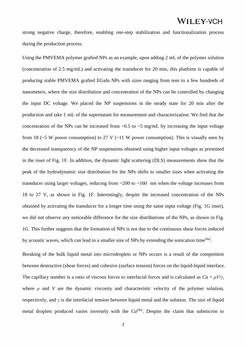
Using the PMVEMA polymer grafted NPs as an example, upon adding 2 mL of the polymer solution
(concentration of 2.5 mg/mL) and activating the transducer for 20 min, this platform is capable of
producing stable PMVEMA grafted EGaIn NPs with sizes ranging from tens to a few hundreds of
nanometers, where the size distribution and concentration of the NPs can be controlled by changing
the input DC voltage. We placed the NP suspensions in the steady state for 20 min after the
production and take 1 mL of the supernatant for measurement and characterization. We find that the
concentration of the NPs can be increased from ~0.5 to ~5 mg/mL by increasing the input voltage
from 18 (~5 W power consumption) to 27 V (~11 W power consumption). This is visually seen by
the decreased transparency of the NP suspensions obtained using higher input voltages as presented
in the inset of Fig. 1F. In addition, the dynamic light scattering (DLS) measurements show that the
peak of the hydrodynamic size distribution for the NPs shifts to smaller sizes when activating the
transducer using larger voltages, reducing from ~200 to ~160 nm when the voltage increases from
18 to 27 V, as shown in Fig. 1F. Interestingly, despite the increased concentration of the NPs
obtained by activating the transducer for a longer time using the same input voltage (Fig. 1G inset),
we did not observe any noticeable difference for the size distributions of the NPs, as shown in Fig.
1G. This further suggests that the formation of NPs is not due to the continuous shear forces induced
by acoustic waves, which can lead to a smaller size of NPs by extending the sonication time[4a].
Breaking of the bulk liquid metal into microdroplets or NPs occurs is a result of the competition
between destructive (shear forces) and cohesive (surface tension) forces on the liquid-liquid interface.
The capillary number is a ratio of viscous forces to interfacial forces and is calculated as Ca = μV/γ,
where μ and V are the dynamic viscosity and characteristic velocity of the polymer solution,
respectively, and γ is the interfacial tension between liquid metal and the solution. The size of liquid
metal droplets produced varies inversely with the Ca[9a]. Despite the claim that submicron to

8
nanosized particles of low-melting-point metal such as bismuth can be produced with a narrow size
distribution simply by stirring at a speed of few hundreds of rpm[12], it is very unlikely to happen in
our case as the Ca is too small (~0.02) even we applied a high stirring speed of 1600 rpm, as shown
in Fig. S2A. Our previous study shows that even with a large Ca of ~2 within a flow-focusing
microfluidic device, only large liquid metal microdroplets with a diameter of ~100 µm can be
produced[9a]. As a result, we only observed the production of large non-spherical liquid metal
droplets (major axis of ~200 µm) after vigorously stirring the bulk liquid metal within the polymer
solution at a high speed of 1600 rpm (see Fig. S2A). We also tried to increase the Ca using a much
more viscous liquid such as polydimethylsiloxane (PDMS); however, we could only break the liquid
metal into polydispersed droplets with the diameter of tens of micrometers, as shown in Fig. S2B.
The polydispersity of the produced liquid metal droplets using such a stirring method is due to the
large Reynolds number (~2×10⁴) at the high stirring speed (1600 rpm). Consequently, the flow is
rather turbulent and no constant shear can be induced to evenly break the bulk liquid metal into
monodispersed microdroplets or NPs.
We further compared the production of liquid metal NPs using this ultrasonic device with other
methods, including sonication using bath or probes, as well as microfluidics-assisted sonication [9b].
For the production using a sonication bath, an 8 mL glass vial contains 2 mL polymer solution and
300 µL EGaIn was sonicated using a 60 W sonication bath for 20 min. For the production using a
sonication probe, an 8 mL glass vial contains 2 mL polymer solution and 300 µL EGaIn was
sonicated using a sonication probe with a 90 W output power for 20 min. We placed the NP
suspensions in a steady state for 20 min after production and take 1 mL of the supernatant for the
DLS measurements. We discovered that the device presented in this paper can produce NPs with a
size distribution that is narrower and at least two times smaller in comparison with other methods
using less power, and also the distribution of the size is always smaller than 500 nm while other
methods may produce a large portion of particles in micro-sized dimensions, as detailed in Fig. 1H.
9
Figure 1. Production of EGaIn nanoparticles using the mini ultrasonic platform. (A) Exploded
schematic of the platform. (B) Actual image of the assembled device. (C) Numerical simulation of
the displacement on the top of the PZT transducer upon the application of a 1.71 MHz signal. (D)
Schematic illustrating the mechanism for producing EGaIn nanoparticles. (E) Snap shots showing
the EGaIn droplet within the device before and after activating the transducer. (F) Hydrodynamic
size distributions for the PMVEMA grafted NPs obtained using different input voltages; the inset
shows the image of the EGaIn NP suspensions. (G) Hydrodynamic size distributions of the NPs
produced using different production time, the input voltage was kept at 24 V; the inset shows the
image of the EGaIn NP suspensions. (H) Hydrodynamic size distributions of the EGaIn NPs
produced using the ultrasonic device presented in this paper in comparison with other methods.
10
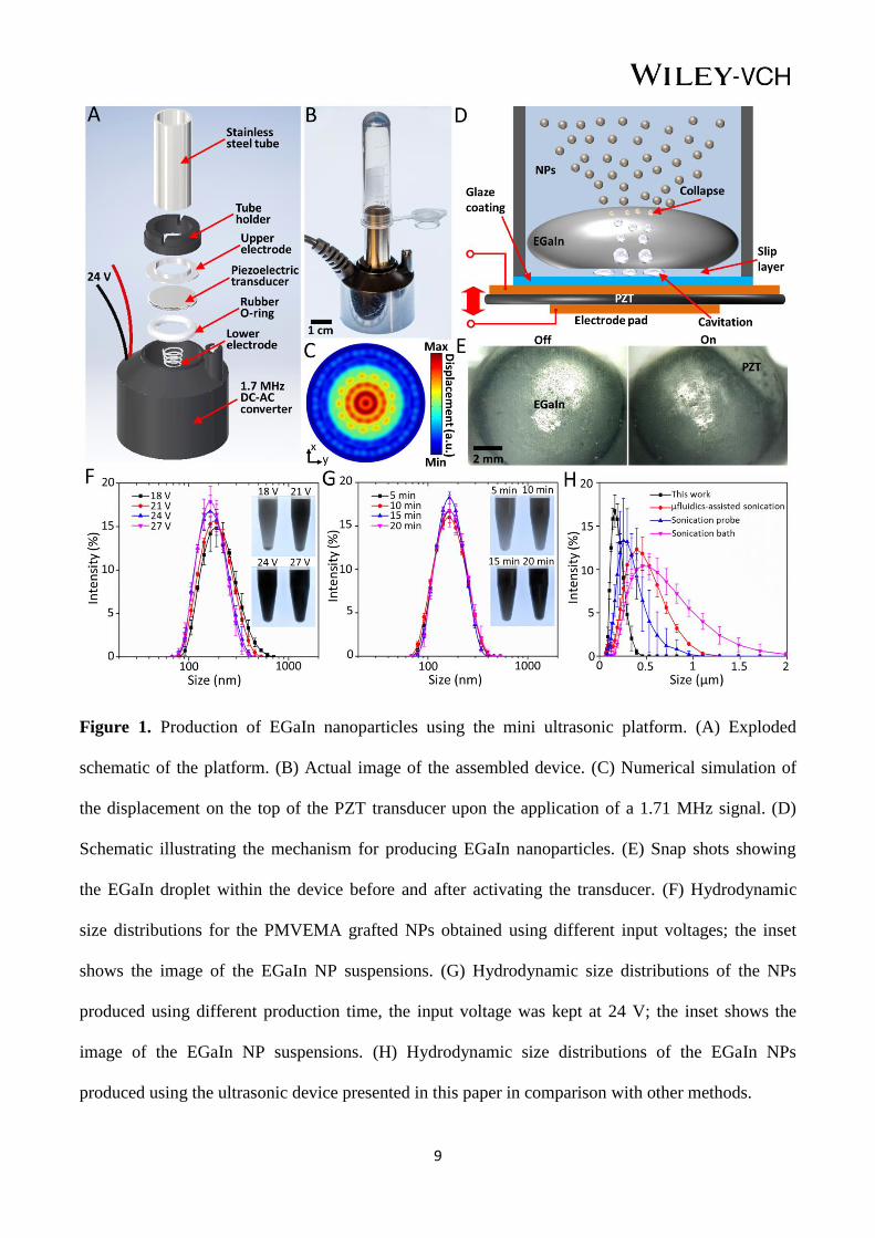
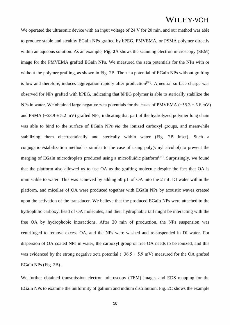
We operated the ultrasonic device with an input voltage of 24 V for 20 min, and our method was able
to produce stable and stealthy EGaIn NPs grafted by bPEG, PMVEMA, or PSMA polymer directly
within an aqueous solution. As an example, Fig. 2A shows the scanning electron microscopy (SEM)
image for the PMVEMA grafted EGaIn NPs. We measured the zeta potentials for the NPs with or
without the polymer grafting, as shown in Fig. 2B. The zeta potential of EGaIn NPs without grafting
is low and therefore, induces aggregation rapidly after production[9b]. A neutral surface charge was
observed for NPs grafted with bPEG, indicating that bPEG polymer is able to sterically stabilize the
NPs in water. We obtained large negative zeta potentials for the cases of PMVEMA (−55.3 ± 5.6 mV)
and PSMA (−53.9 ± 5.2 mV) grafted NPs, indicating that part of the hydrolyzed polymer long chain
was able to bind to the surface of EGaIn NPs via the ionized carboxyl groups, and meanwhile
stabilizing them electrostatically and sterically within water (Fig. 2B inset). Such a
conjugation/stabilization method is similar to the case of using poly(vinyl alcohol) to prevent the
merging of EGaIn microdroplets produced using a microfluidic platform[13]. Surprisingly, we found
that the platform also allowed us to use OA as the grafting molecule despite the fact that OA is
immiscible to water. This was achieved by adding 50 µL of OA into the 2 mL DI water within the
platform, and micelles of OA were produced together with EGaIn NPs by acoustic waves created
upon the activation of the transducer. We believe that the produced EGaIn NPs were attached to the
hydrophilic carboxyl head of OA molecules, and their hydrophobic tail might be interacting with the
free OA by hydrophobic interactions. After 20 min of production, the NPs suspension was
centrifuged to remove excess OA, and the NPs were washed and re-suspended in DI water. For
dispersion of OA coated NPs in water, the carboxyl group of free OA needs to be ionized, and this
was evidenced by the strong negative zeta potential (−36.5 ± 5.9 mV) measured for the OA grafted
EGaIn NPs (Fig. 2B).
We further obtained transmission electron microscopy (TEM) images and EDS mapping for the
EGaIn NPs to examine the uniformity of gallium and indium distribution. Fig. 2C shows the example

11
of PMVEMA grafted NPs, from which we can see a thin layer of oxide formed on the NP surface,
and the grafting polymer is not obvious due to its small thickness and similar contrast to the
background (zoomed in image of Fig. 2C). Despite that the surface composition of gallium-indium
alloys is dominated by indium in high vacuum, the shell of the alloy primarily consists of gallium
oxide because indium is less prone to be oxidized and thermodynamically gallium oxide is
preferential over indium oxide[14]. The growth of the gallium oxide could be controlled through
thiolation[15], thermal oxidation[16] or electrochemistry[17]. Thiolation can mitigate (but not eliminate)
the growth of gallium oxide[15]. For thermal oxidation, the thickness, texture and roughness of the
oxide layer is temperature-dependent that it grows thicker and rougher with increasing
temperature[16]. While in electrochemistry, the oxide skin becomes thicker with increasing oxidative
potential[17]. To further examine the thickness of the oxide layer and the grafted PMVEMA, we
conducted EDS mapping for a single NP using a TEM grid coated with a lacey carbon film, as
shown in Fig. S3, from which we discovered that the thickness of the oxide layer and the grafted
polymer are ~3 and ~2.5 nm, respectively. No diffraction pattern was observed from the convergent-
beam electron diffraction (CBED) measurement (see Fig. S4), indicating that the core of NPs is
liquid. The EDS mapping indicates a uniform distribution of gallium and indium within the NPs (Fig.
2C). The temperature measured for the suspension was below 40 ºC when activating the transducer
less than 30 min (see Fig. S5); this minimized the chance of inducing dealloying and morphological
transformation observed for liquid metal NPs caused by oxidation after exposing to a high
temperature (~70 ˚C)[7a]. The use of polymers and OA for stabilizing the produced EGaIn
nanoparticles represents a significant advance in comparison to previous reports that use thiol-
functionalized molecules for stabilization[1b,5a,5b]. In comparison, our approach for nanoparticle
anchoring avoids the use of thiol groups that induce unpleasant odors and are prone to oxidation
reactions and as a consequence, inducing fouling within biological systems.
12
Figure 2. Characterization of the produced EGaIn NPs. (A) SEM image of the PMVEMA grafted
EGaIn NPs. (B) Zeta potentials for the EGaIn NPs with/without grafting. (C) TEM images and EDS
mapping of the PMVEMA grafted EGaIn NPs.
After obtaining the stable NPs suspensions, we further studied their stability within water over a
longer period of time (120 h). We have previously showed that bPEG grafted EGaIn NPs are prone
to oxidization and formation of gallium oxide nanodisks within 48 h without the presence of an
antioxidant such as trisodium citrate[9b]. Interestingly, for the case of PMVEMA grafted NPs, we
found that the NPs suspension is relatively stable (can be re-suspended) but became more transparent
after 12 h, as shown in Fig. 3A. We obtained the TEM image for the EGaIn NPs 120 h after
production (see Fig. 3A) and observed the formation of core-shell structured NPs. Most of the NPs
have a thick layer of gallium oxide shell (10-20 nm) and an indium-rich core, as evidenced by the
EDS spectrum. The CBED results indicate that the core of the NPs became solid (see Fig. S6), and
this can be attributed to the dealloying process induced by the gradual oxidation of metallic gallium

13
on the surface, increasing the content of indium and solidifying the core. In addition, we also
observed the formation of gallium oxide nanodisks (see the TEM image in Fig. 3A), as evidenced by
the EDS spectrum given in Fig. S7. The X-ray diffraction (XRD) and X-ray photoelectron
spectroscopy (XPS) spectra given in Fig. S8 show that the oxide layer on the NPs was mainly
composed of α-Ga2O3 at 0 h, and it gradually became thicker and transformed into GaOOH 120 h
after production. Similar results were obtained for PSMA grafted NPs. We believe that the loss of
liquidity and formation of gallium oxide nanodisks may contribute to the enhanced transparency of
the suspension, as evidenced by the experiments conducted using pure gallium instead of EGaIn,
where the gallium NPs were oxidized and the suspension became transparent 120 h after the
production, as shown in Fig. S9.
On the contrary, the OA grafted NPs are very stable with no change of the particle concentration and
morphology observed over the period of 120 h, as shown in Fig. 3B. The CBED measurements prove
that the NPs were still liquid and the EDS spectrum indicates no hydrolysis and oxidation occurred
for the NPs (Fig. 3B). Such an unprecedented stability is due to the formation of an insulation layer
from the hydrophobic tails of OA (see the inset of the EDS spectrum). Our DLS measurements show
that the peak of the distribution for PMVEMA grafted NPs shifted towards the larger size by ~40 nm
due to the formation of nanodisks after 120 h (see Fig. 3C), while no shift of the peak was observed
for OA grafted NPs. We further compared the UV-vis spectra for the suspensions of PMVEMA and
OA grafted NPs 120 h after production, as shown in Fig. S10, for which no peak was detected for
OA coated NPs while a broad peak at ~330 nm was observed for the case of PMVEMA. This further
confirms the formation of solid indium NPs[18].
Such an excellent stability and the presence of carboxyl functioning groups for OA grafted NPs can
allow us to conduct further functionalization. We conducted a proof-of-concept experiment to
conjugate Rhodamine 123 (R123) fluorescent dye to the OA grafted EGaIn NPs, where a 1-ethyl-3-
(3- dimethylaminopropyl)carbodiimide (EDC)-mediated crosslinking method was used. Briefly,

14
EDC (final concentration of 1 mM) was firstly added into 3 mL of the NPs suspension to react with
carboxylic acid groups, and then the unreacted EDC was removed using dialysis tubing (2000 Da
MWCO). Next, we added 5 µL of R123 solution (concentration of 10 mg/mL) into the NP
suspension to allow for the formation of amide bonds between the R123 and the NPs. The
conjugated NPs were later washed with dialysis tubing (2000 Da MWCO) and we examined the
functionalization using a fluorescence spectrophotometer. The obtained emission spectra for the
R123 solution, bare EGaIn NP suspension, and R123-conjugated EGaIn (R123-EGaIn) NP
suspension, are given in Fig. 3D. The R123 solution has an emission peak at ~530 nm and the
presence of such a peak for the spectrum obtained with the R123-conjugated EGaIn NP suspension
clearly proved the success of functionalization. The bright field and fluorescent images for the dry
R123-conjugated EGaIn NP cluster are given in Fig. S11, in which we can clearly see the bright
green-colored fluorescent light emitted from the NPs. Such a functionalization process for EGaIn
NPs is only possible for a very stable suspension where no oxidation and aggregation of NPs should
occur due to the time consuming particle washing process using dialysis tubing (a few days), thus,
the use of OA for grafting EGaIn NPs within our innovative platform certainly represent a significant
advance in comparison to previously reported methods.
We envisioned that such a stable EGaIn NP system may enable various bioapplications and therefore,
we further examined the cytotoxicity of EGaIn NPs grafted with different molecules on MCF-7 cell
line using the Alamar Blue assay (see Experimental part for details). Fig. 3E shows the viability of
the cells upon the 24 h exposure to the NPs with different concentrations; we observed that the
viability of MCF-7 cells slightly decreased as the concentration of the NPs was increased to 0.1
mg/mL for the cases of PMVEMA, PSMA, and bPEG grafted NPs, while no significant cytotoxicity
was observed for OA grafted NPs.

15
Figure 3. Stability of the NP suspensions. EGaIn NP suspension, TEM image, and EDS spectrum for
NPs grafted using (A) PMVEMA, and (B) OA over the duration of 120 h. (C) DLS size distribution
for PMVEMA grafted NPs 0 and 120 h after production. (D) Normalized emission intensity for the
R123 solution, bare EGaIn NP, and R123-conjugated EGaIn NP suspensions. (E) The effect of
concentration for NPs grafted with different molecules on the survival rates of MCF-7 cells.
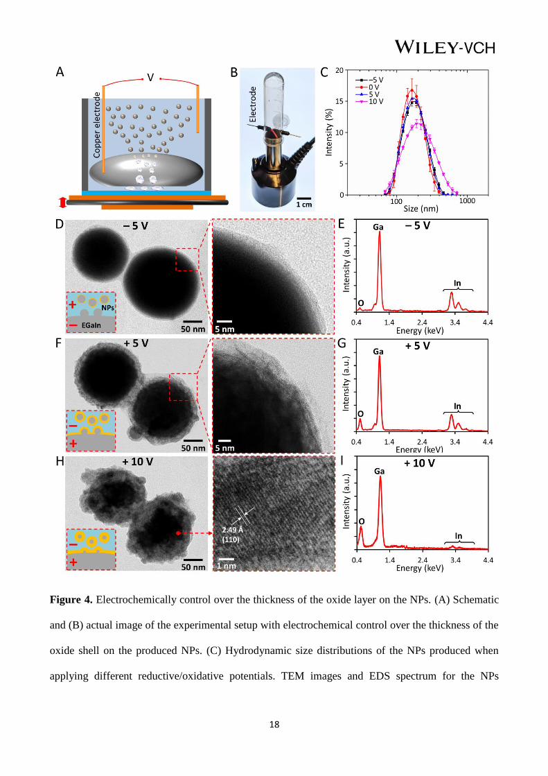
Based on our understanding of the NPs production mechanism elaborated in Fig. 1, where the NPs
were produced due to the collapse of the cavities at the EGaIn-solution interface, we hypothesized
that the thickness of the oxide shell on the NPs can be controlled electrochemically in this platform
upon the application of a reductive or oxidative potential to the bulk EGaIn droplet during the
production [19]. We conducted a proof-of-concept experiment to verify our hypothesis, and the
schematic and actual image depicting the experimental setup is given in Figs. 4A and B, respectively.

16
We electrochemically reduced/oxidized the surface of EGaIn via a pair of copper electrodes in
contact with the EGaIn droplet and the surrounding suspending medium, respectively. In this study,
we used a PMVEMA solution as the suspending medium due to its relatively high electrical
conductivity (~2 mS/cm). We firstly examined the size distributions of the NPs at different
reductive/oxidative voltages, as shown in Fig. 4C. Upon the activation of the transducer and applying
a –5 V reductive potential to the liquid metal, we observed a slight peak shift of the size distribution
towards larger sizes. This could probably due to the increased surface tension of EGaIn after
removing the oxide layer electrochemically[7b]. We also observed a shift of the size distribution
towards larger values when an oxidative potential was applied during the production process, and the
size distribution was broadened after applying larger oxidative potentials (Fig. 4C). This can be
attributed to the formation of thicker and solid oxide layer that may hinders the formation of EGaIn
NPs from the surface.
When we investigate the produced NPs using TEM, we found that for the case of the NPs produced
with the application of a –5 V reductive potential, no obvious difference was observed for the NPs in
comparison to the case without applying a voltage, as shown in Fig. 4D. The inset of Fig. 4D shows
the schematic of the NPs production, where the produced NPs can be oxidized by the oxygen
dissolved into the PMVEMA solution. The EDS spectrum given in Fig. 4E indicates the proper
composition of gallium and indium within the NPs with minimum oxidation occurred.
Interestingly, a thick oxide shell (~15 nm) was formed on the obtained NPs when we applied a +5 V
oxidative potential to the EGaIn droplet during the production, as shown in Fig. 4F. The oxide shell
is mainly composed of α-Ga2O3, as evidenced by the XRD and XPS spectra given in Fig. S12. We
believe this is due to the fact that such a thick oxide layer was already formed on the surface of liquid
metal before liberating NPs, and upon the collapse of cavities that NPs with a thick oxide layer were
produced, as depicted in the Fig. 4F inset. The EDS spectrum given in Fig. 4G confirms the
oxidation with the appearance of the oxygen peak. When we further increase the oxidative potential

17
to +10 V, we found that the produced NPs were heavily oxidized and became non-spherical, as
shown in Fig. 4H. Such heavily oxidized NPs lost their liquidity, as indicated by the diffraction
pattern given in the magnified image in Fig. 4H. The increase in the intensity of the oxygen peak,
and the decrease in the intensity of the indium peaks (see Fig. 4I) clearly show the formation of
gallium oxide and only a small trace amount of indium exists within the NPs. This is probably due to
the fact that gallium is much more prone to oxidation compared to indium and therefore, only a small
amount of gallium-indium alloy can be incorporated into the produced NPs (see the inset of Fig. 4H).
The observed formation of a thick oxide layer on the surface of NPs explains the shift of the size
distribution towards the larger sizes when oxidative potentials were applied (see Fig. 4C).
Following our initial studies on the EGaIn NPs produced using this platform, we also found that due
to the smaller and narrower size distribution of the produced NPs in comparison to previous
reports[9b], the optical properties of the EGaIn NP suspension can be modified after forming
nanosized liquid metal marbles[20] coated with silver (Ag) NPs, as shown in Figs. S13 and S14. We
discovered that the AgNP coating on the surface can introduce a strong surface plasma resonance
due to the strong interaction of the AgNPs with light. This interaction results in strong scattering and
absorption properties, leading to a significant absorption peak at ~418 nm for the nanosized liquid
metal marbles (see Figs. S13 and S14).
18
Figure 4. Electrochemically control over the thickness of the oxide layer on the NPs. (A) Schematic
and (B) actual image of the experimental setup with electrochemical control over the thickness of the
oxide shell on the produced NPs. (C) Hydrodynamic size distributions of the NPs produced when
applying different reductive/oxidative potentials. TEM images and EDS spectrum for the NPs
19
produced with the application of a (D-E) –5 V, (F-G) + 5 V, and (H-I) +10 V with respect to the
surrounding medium. The insets show the schematics of the NPs production process.
3. Conclusion
In summary, we developed a novel ultrasonic platform to nebulize liquid metal within aqueous
media for the versatile and efficient production of functional EGaIn liquid metal NPs. We fully
characterized the size distribution of NPs and discovered that the median diameter of NPs can be
tuned by the magnitude of the applied voltage and not by increasing the process duration. We
discovered that various polymers and oleic acid can be directly used in this platform for grafting the
surface of EGaIn liquid metal to stabilize the produced NPs in aqueous media. Based on the
excellent stability of the produced EGaIn NPs, we showed that the produced NPs can be further
functionalized without inducing oxidation and aggregation of the NPs. We also demonstrated that the
grafted NPs have little or no effect on the viability of MCF-7 cells at the concentration of 0.1 mg/mL.
Most importantly, this platform allows us to electrochemically control the thickness of the oxide
shell on the produced NPs. As such, the simplicity and versatility of the ultrasonic platform, together
with the multifaceted functionality of the produced EGaIn NPs, possess the vast potential to enable a
new horizon for developing future liquid metal-based optical, electronic, catalytic and biomedical
applications.
20
Experimental Section
Chemical preparation: Poly(methyl vinyl ether-alt-maleic anhydride) (PMVEMA, MW of 216 kDa),
poly(styrene-co-maleic anhydride) (PSMA, MW of 224 kDa), oleic acid, dialysis tubing (2000 Da
MWCO), Rhodamine 123, EDC, and silver nitrate (AgNO3) were purchase from Sigma Aldrich,
USA. Ultrasonic mist makers were purchased from AGPTEK, USA. PMVEMA and PSMA polymer
solutions were prepared by dissolving 50 mg PMVEMA and PSMA into 20 mL of deionized (DI)
water, respectively (final concentration of 2.5 mg/mL), and mixed for 24 hours to allow for the full
hydrolysis; the pH of the solutions was ~3.0.
Polymer synthesis: Brushed polyethylene glycol (bPEG, MW of 20 kDa) was synthesized using the
reversible addition-fragmentation chain transfer (RAFT) polymerization techniques[21]. Briefly, a
solution of RAFT agent, 2, 2’-azobis(isobutyronitrile) (AIBN), and monomers in dioxane was added
to a polymerization ampoule. The solution was degassed by sparging with nitrogen for 20 min and
the ampoule was sealed under nitrogen, while the reaction was stirred at 65 °C. Samples were then
taken for 1HNMR spectroscopy and GPC analysis. The bPEG solution was prepared by adding 50
mg of the bPEG into 10 mL DI water.
Alamar Blue assay: MCF-7 (human breast cancer cell line, ATCC) were grown in Dulbecco’s
Modified Eagle Media (DMEM) culture media with 10% Fetal Bovine Serum (FBS). MCF7 cells
(1×10⁴ cells/well) were exposed to materials (0.002, 0.01, 0.025, and 0.1 mg/mL) for 24 h in 96-well
plates, with the final volume of 100 µL. Cell culture medium was used as a control. After exposure,
the suspensions were removed and the cells were incubated with 10% Alamar Blue (Invitrogen) for 4
h at 37 °C. A microplate reader (CLARIOstar, BMG LABTECH) was used to read the fluorescence
at 500 nm excitation and 530 nm emission. Background values (10% Alamar Blue in cell culture
medium) were subtracted from each well and the average fluorescent intensity of the triplicates was
calculated.
21
Characterization: Scanning electron microscopy (SEM) images were obtained using a JEOL JSM-
7500FA scanning electron microscope. Transmission electron microscopy (TEM) images were
obtained using a JEOL JEM-2011 transmission electron microscope. Energy-dispersive X-ray
spectroscopy (EDS) maps were measured using JEOL JEM-ARM200f scanning transmission
electron microscope (STEM). A zeta-sizer (Zetasizer Nano ZS, Marvern Instrument, USA) was used
to measure the size distribution of the obtained EGaIn nanoparticles. The concentration of the EGaIn
nanoparticles was measured by weighing the dried suspensions. UV-vis spectra were obtained using
a UV/vis spectrophotometer (Uv-5200Pc, Metash instrument Co., Ltd, China). The fluorescent
emission spectra were obtained using a fluorescence spectrophotometer (Cary Eclipse 500, Agilent
Technologies, USA). XRD (MMA, GBC Scientific Equipment LLC, Hampshire, IL, USA) was used
to evaluate the composition of the oxide layer. XPS spectra were obtained using a PHOIBOS 100
Analyser from SPECS, Berlin, Germany; Al K αX-rays.
Acknowledgements
Dr. Shi-Yang Tang is the recipient of the Vice-Chancellor’s Postdoctoral Research Fellowship
funded by the University of Wollongong. Prof. Tom P. Davis and Dr. Ruirui Qiao are supported by
the Australian Research Council Centre of Excellence in Convergent Bio-Nano Science and
Technology (project number CE140100036). Prof. Michael Dickey gratefully acknowledges support
from the NSF (CMMI-0954321) and NSF Research Triangle MRSEC on Programmable Soft Matter
(DMR-1121107). The authors acknowledge use of the facilities and the assistance of Dr. David
Mitchell at the UOW Electron Microscopy Centre.
Supporting Information
Supporting Information is available from the Wiley Online Library.
22
Reference
[1] a) M. D. Dickey, ACS Appl. Mater. Interfaces 2014, 6, 18369-18379; b) L. R. Finkenauer, Q. Lu,
I. F. Hakem, C. Majidi, M. R. Bockstaller, Langmuir 2017, 33, 9703-9710; c) T. Liu, P. Sen, C.-
J. Kim, J. Microelectromech. Syst. 2012, 21, 443-450.
[2] a) K. Khoshmanesh, S.-Y. Tang, J. Y. Zhu, S. Schaefer, A. Mitchell, K. Kalantar-Zadeh, M. D.
Dickey, Lab Chip 2017, 17, 974-993; b) S.-Y. Tang, J. Zhu, V. Sivan, B. Gol, R. Soffe, W.
Zhang, A. Mitchell, K. Khoshmanesh, Adv. Funct. Mater. 2015, 25, 4445-4452; c) Q. Wang, Y.
Yu, J. Liu, Adv. Eng. Mater. 2018, 20, 1700781.
[3] a) Y. Lin, C. Cooper, M. Wang, J. J. Adams, J. Genzer, M. D. Dickey, Small 2015, 11, 6397-
6403; b) M. D. Bartlett, N. Kazem, M. J. Powell-Palm, X. Huang, W. Sun, J. A. Malen, C.
Majidi, Proc. Natl. Acad. Sci. U. S. A. 2017, 201616377; c) Q. Wang, Y. Yu, J. Yang, J. Liu,
Adv. Mater. 2015, 27, 7109-7116; d) Y. Chen, T. Zhou, Y. Li, L. Zhu, S. Handschuh‐Wang, D.
Zhu, X. Zhou, Z. Liu, T. Gan, X. Zhou, Adv. Funct. Mater. 2018, 28, 1706277; e) L. Tang, S.
Cheng, L. Zhang, H. Mi, L. Mou, S. Yang, Z. Huang, X. Shi, X. Jiang, iScience 2018, 4, 302-
311.
[4] a) W. Zhang, J. Z. Ou, S.-Y. Tang, V. Sivan, D. D. Yao, K. Latham, K. Khoshmanesh, A.
Mitchell, A. P. O'Mullane, K. Kalantar-zadeh, Adv. Funct. Mater. 2014, 24, 3799-3807; b) N.
Syed, A. Zavabeti, M. Mohiuddin, B. Zhang, Y. Wang, R. S. Datta, P. Atkin, B. J. Carey, C. Tan,
J. van Embden, J. Z. Ou, T. Daeneke, K. Kalantar-zadeh, Adv. Funct. Mater. 2017, 27, 1702295.
[5] a) S. A. Chechetka, Y. Yu, X. Zhen, M. Pramanik, K. Pu, E. Miyako, Nat. Commun. 2017, 8,
15432; b) Y. Lu, Q. Hu, Y. Lin, D. B. Pacardo, C. Wang, W. Sun, F. S. Ligler, M. D. Dickey, Z.
Gu, Nat. Commun. 2015, 6, 10066; c) Y. Yu, E. Miyako, iScience 2018, 3, 134-148; d) X. Sun,
B. Yuan, W. Rao, J. Liu, Biomaterials 2017, 146, 156-167; e) Y. Lu, Y. Lin, Z. Chen, Q. Hu, Y.
Liu, S. Yu, W. Gao, M. D. Dickey, Z. Gu, Nano Letters 2017, 17, 2138-2145.
[6] E. J. Markvicka, M. D. Bartlett, X. Huang, C. Majidi, Nat. Mater. 2018, 17, 618-624.
23
[7] a) Y. Lin, Y. Liu, J. Genzer, M. D. Dickey, Chem. Sci. 2017, 8, 3832-3837; b) S.-Y. Tang, B.
Ayan, N. Nama, Y. Bian, J. P. Lata, X. Guo, T. J. Huang, Small 2016, 12, 3861-3869; c) J. N.
Hohman, M. Kim, G. A. Wadsworth, H. R. Bednar, J. Jiang, M. A. LeThai, P. S. Weiss, Nano
Letters 2011, 11, 5104-5110.
[8] a) S. Çınar, I. D. Tevis, J. Chen, M. Thuo, Sci. Rep. 2016, 6, 21864; b) I. D. Tevis, L. B.
Newcomb, M. Thuo, Langmuir 2014, 30, 14308-14313.
[9] a) S.-Y. Tang, I. D. Joshipura, Y. Lin, K. Kalantar-Zadeh, A. Mitchell, K. Khoshmanesh, M. D.
Dickey, Adv. Mater. 2016, 28, 604-609; b) S.-Y. Tang, R. Qiao, S. Yan, D. Yuan, Q. Zhao, G.
Yun, T. P. Davis, W. Li, Small 2018, 1800118.
[10] D. Kirpalani, F. Toll, J. Chem. Phys. 2002, 117, 3874-3877.
[11] a) J. Feng, M. Roché, D. Vigolo, L. N. Arnaudov, S. D. Stoyanov, T. D. Gurkov, G. G.
Tsutsumanova, H. A. Stone, Nat. Phys. 2014, 10, 606; b) A. Zavabeti, J. Z. Ou, B. J. Carey, N.
Syed, R. Orrell-Trigg, E. L. Mayes, C. Xu, O. Kavehei, A. P. O’mullane, R. B. Kaner, K.
Kalantar-zadeh, T. Daeneke, Science 2017, 358, 332-335.
[12] Y. Wang, Y. Xia, Nano Letters 2004, 4, 2047-2050.
[13] J. Thelen, M. D. Dickey, T. Ward, Lab Chip 2012, 12, 3961-3967.
[14] M. Dumke, T. Tombrello, R. Weller, R. Housley, E. Cirlin, Surf. Sci. 1983, 124, 407-422.
[15] Z. J. Farrell, C. Tabor, Langmuir 2017, 34, 234-240.
[16] J. Cutinho, B. S. Chang, S. Oyola-Reynoso, J. Chen, S. S. Akhter, I. D. Tevis, N. J. Bello, A.
Martin, M. C. Foster, M. M. Thuo, ACS Nano 2018, 12, 4744-4753.
[17] M. R. Khan, C. B. Eaker, E. F. Bowden, M. D. Dickey, Proc. Natl. Acad. Sci. U. S. A. 2014, 111,
14047-14051.
[18] F. Magnan, J. Gagnon, F.-G. Fontaine, D. Boudreau, Chem. Commun. 2013, 49, 9299-9301.
[19] C. B. Eaker, M. D. Dickey, Appl. Phys. Rev. 2016, 3, 031103.

24
[20] V. Sivan, S.-Y. Tang, A. P. O'Mullane, P. Petersen, N. Eshtiaghi, K. Kalantar-zadeh, A.
Mitchell, Adv. Funct. Mater. 2013, 23, 144-152.
[21] a) C. Boyer, V. Bulmus, T. P. Davis, V. Ladmiral, J. Liu, S. Perrier, Chem. Rev. 2009, 109,
5402-5436; b) T. Blin, A. Kakinen, E. H. Pilkington, A. Ivask, F. Ding, J. F. Quinn, M. R.
Whittaker, P. C. Ke, T. P. Davis, Polym. Chem. 2016, 7, 1931-1944.