functional electrolytes - icmab
TRANSCRIPT
Functional ElectrolytesRecent Advances in Development of Additives
for Impedance Reduction
International Battery Association meeting 2013
(Joint Venture of The Dow Chemical Company and UBE Industries, Ltd)
K. Abe, M. Colera, K. Shimamoto, M. Kondo, K. Miyoshi
14 March, 2013

'92 Started High Purity DMC Production '94 Started Commercial‐Production of MEC and DEC'96 Started Lithium Battery Electrolyte Research'97 Commercial‐Production of “Functional Electrolytes”
'11 Established Spain Development Branch (Castellón)
'11 UBE‐Dow Joint Venture Launched
“Functional Electrolytes” : High Purity + High Performance Electrolytes→ Functions are introduced with a small amount of additives.
UBE Industries, Ltd., Battery and Power Supply in Techno‐Frontier Symposium, Makuhari, Japan, 14 Apr. (1999)
2
History of Our Electrolyte Development

3
② Gas Phase Process (UBE)
① Phosgene Process(Classic)
③ Trans Esterification Process
High Chlorine Contents
Containing Many Impurities
Ultra‐pure DMC
UBE DMC Plant
Typical DMC Commercial Process
0
10
20
30
40
50
60
0 20 40 60 80 100
Time (day)
HF concentration (ppm)
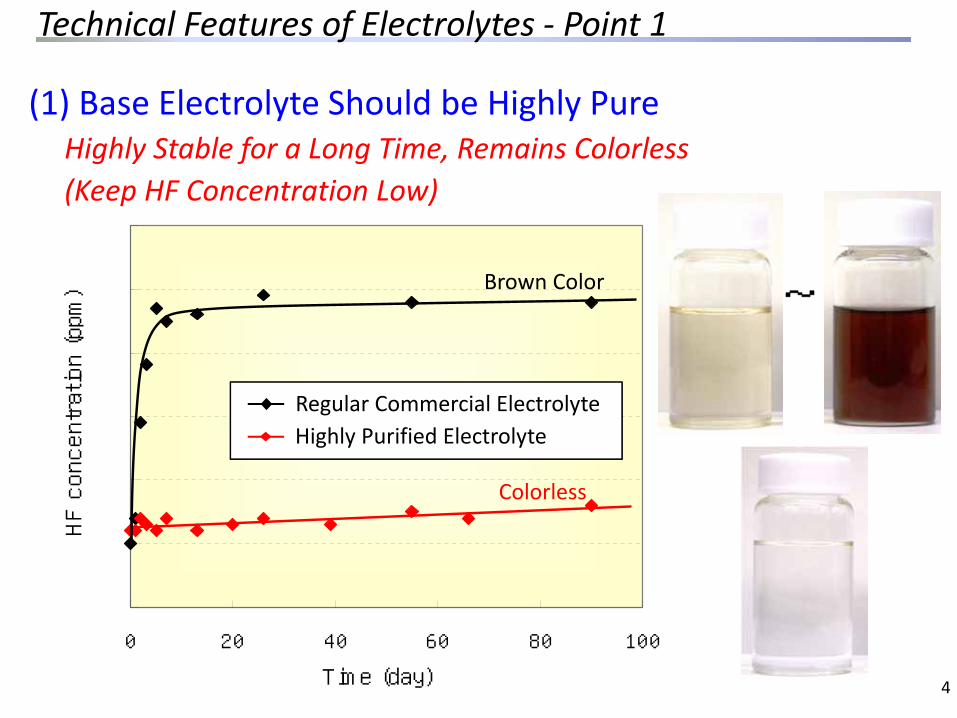
Regular commercial electrolyte
UBE electrolyte
Brown Color
Colorless
(1) Base Electrolyte Should be Highly Pure Highly Stable for a Long Time, Remains Colorless(Keep HF Concentration Low)
Regular Commercial ElectrolyteHighly Purified Electrolyte
4
~
Technical Features of Electrolytes ‐ Point 1

(2) Utilization of Additives ( = Functional Electrolytes)(i) Anode Additives(ii) Cathode Additives(iii) Additives for Safety Issues
etc.
Examples of Commercialized Additives
5
Technical Features of Electrolytes ‐ Point 2
*
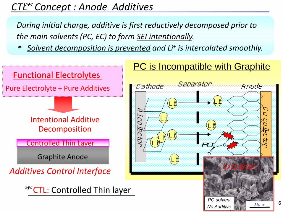
During initial charge, additive is first reductively decomposed prior to the main solvents (PC, EC) to form SEI intentionally.⇒ Solvent decomposition is prevented and Li+ is intercalated smoothly.
Functional Electrolytes Functional Electrolytes Pure Electrolyte + Pure Additives
Additives Control Interface
Intentional Additive Decomposition
Graphite Anode
Controlled Thin Layer
CTL: Controlled Thin layer*
Separator
Cu collector
Al collector
OO
O
Cathode Anode
Li+
PC
PC is Incompatible with Graphite
6
Li+
Li+
Li+
Li+
Li+Li+Li+
PCPC系系添加剤なし添加剤なし
30μmPCPC系系添加剤なし添加剤なし
30μm30μm
Exfoliation
PC solventNo Additive
CTL Concept : Anode Additives
We investigated
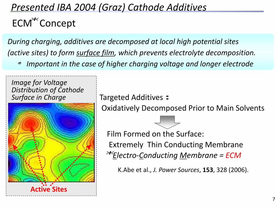
During charging, additives are decomposed at local high potential sites (active sites) to form surface film, which prevents electrolyte decomposition.⇒ Important in the case of higher charging voltage and longer electrode
Image for Voltage Distribution of Cathode Surface in Charge
Active Sites
Film Formed on the Surface:Extremely Thin Conducting MembraneElectro‐Conducting Membrane = ECM
K.Abe et al., J. Power Sources, 153, 328 (2006).
Targeted Additives:Oxidatively Decomposed Prior to Main Solvents
*
*ECM Concept
7
Presented IBA 2004 (Graz) Cathode Additives

8
Oxidation Potential (V)
Curren
t
Curren
t
Oxidation Potential (V)
ShiftPotentialHigher
: Theoretical Line : Actual Line
: Theoretical Line : Actual Line
◆Solo Use ◆Combination Use
Gear Change Concept:Stepwise Shifting Down to Low Gear (= Higher Potential) Like the Image of Engine Breaking of Car Driving
Shifting Oxidation Potential Higher by Combination of Multiple Additives
Additive A
Additive B
Additive CAdditive A
Gear Change Concept : Overcharge Protection
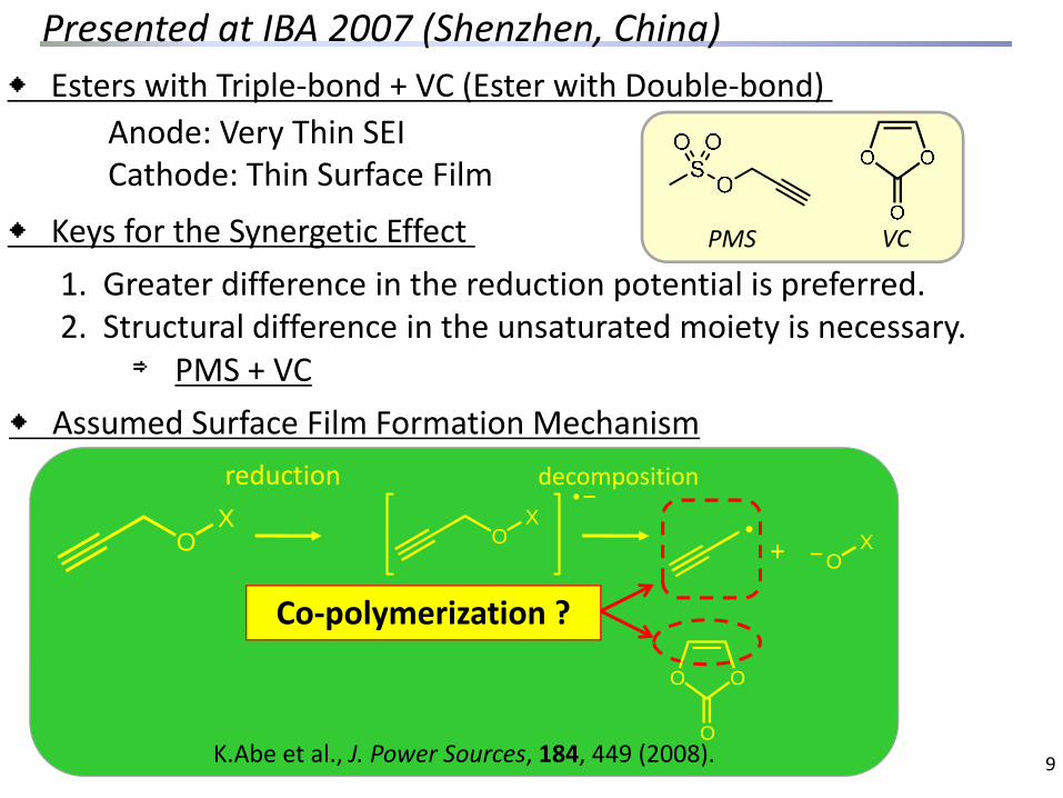
OXO
X
+
reduction decomposition
Co‐polymerization ?
◆ Assumed Surface Film Formation Mechanism
◆ Keys for the Synergetic Effect 1. Greater difference in the reduction potential is preferred.2. Structural difference in the unsaturated moiety is necessary.
⇒ PMS + VC
Anode: Very Thin SEICathode: Thin Surface Film
◆ Esters with Triple‐bond + VC (Ester with Double‐bond)
O O
O
OX
K.Abe et al., J. Power Sources, 184, 449 (2008).
PMS VC
9
Presented at IBA 2007 (Shenzhen, China)

New Additives Derived from PMS
10
・High Reduction Potential・Anode Protection Capability⇒ Surface Protection by Triple bondPMS
Decomposed Product at Anode Works for Cathode Surface Film Formation
Coin Cell(LiCoO2/Artificial Graphite)Base Electrolyte: 1.2M LiPF6 EC/MEC/DMC(30/30/40) DC‐IR: SOC 50%, ‐20oC (Summarized Relative DC‐IR Values in Comparison with the Electrolyte with No Additive)
AB
◆ Experimental
Anode Side Cathode Side
Sulfonate Plays a Key Role for Cathode Surface⇒Effective for Impedance Reduction

60
70
80
90
100
DC
-IR (R
elat
ive
Valu
e, %
)A: Chain‐Type (Monomesylate)
No Additive
◆Initial DC‐IR
11
99% 99%
91%86%
81%
A
Highly Branched Structure Shows Superior Impedance Reduction
60
70
80
90
100
DC
-IR (R
elat
ive
Valu
e, %
)
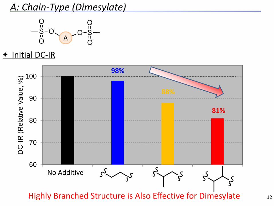
A: Chain‐Type (Dimesylate)
No Additive
12
98%
88%
81%
A
◆Initial DC‐IR
Highly Branched Structure is Also Effective for Dimesylate
60
70
80
90
100
DC
-IR (R
elat
ive
Valu
e, %
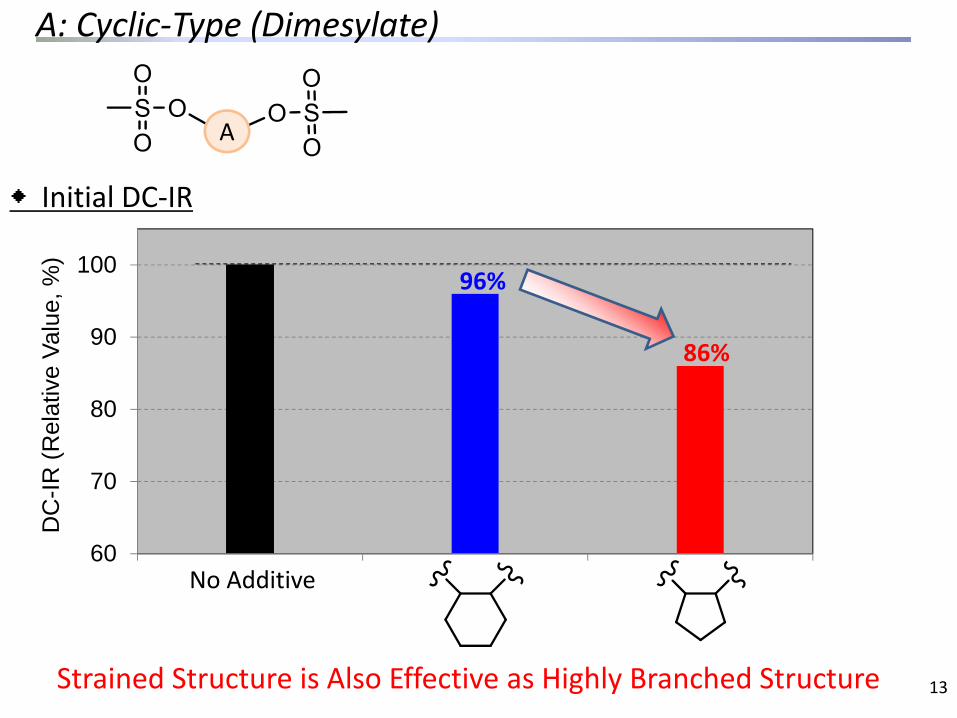
)A: Cyclic‐Type (Dimesylate)
No Additive
13
96%
86%
A
◆Initial DC‐IR
Strained Structure is Also Effective as Highly Branched Structure
60
70
80
90
100
DC
-IR (R
elat
ive
Valu
e, %
)
14
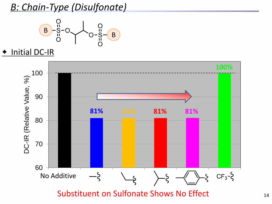
81% 81% 81%
No Additive
100%
81%
B B
◆Initial DC‐IR
Substituent on Sulfonate Shows No Effect
B: Chain‐Type (Disulfonate)
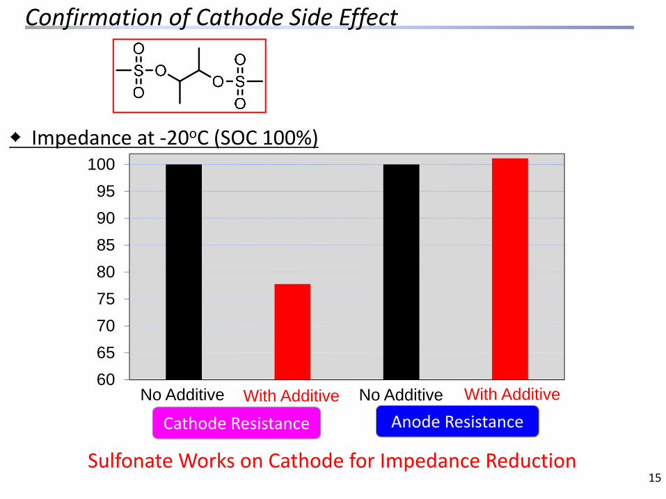
Confirmation of Cathode Side Effect
15Sulfonate Works on Cathode for Impedance Reduction
◆Impedance at ‐20oC (SOC 100%)
Anode Resistance
6065707580859095
100
Cathode ResistanceWith Additive With AdditiveNo Additive No Additive

Cathode Surface Film Analysis
145PF6101PO2F2
85POF279PO3
63PO2
95SO4CH380SO3
64SO248SO
P Atom
S Atom
◆TOF‐SIMS
In the Presence of Additive LiPF6 Incorporation is
Decreased Sulfonate Incorporation is
Observed
16
No AdditiveWith Additive
No AdditiveWith Additive
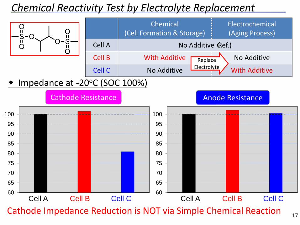
Chemical Reactivity Test by Electrolyte Replacement
Cathode Impedance Reduction is NOT via Simple Chemical Reaction 17
◆Impedance at ‐20oC (SOC 100%)
Chemical(Cell Formation & Storage)
Electrochemical(Aging Process)
Cell A No Additive(Ref.)
Cell B With Additive No Additive
Cell C No Additive With AdditiveReplace
Electrolyte
60
65
70
75
80
85
90
95
100
60
65
70
75
80
85
90
95
100
Anode ResistanceCathode Resistance
Cell B Cell BCell A Cell C Cell A Cell C
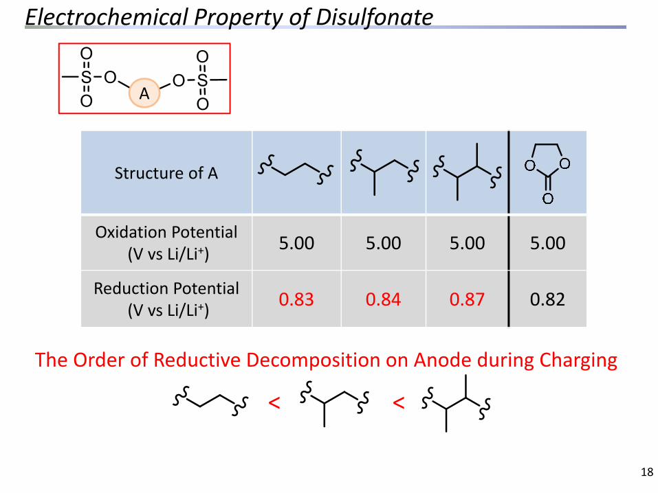
Structure of A
Oxidation Potential(V vs Li/Li+) 5.00 5.00 5.00 5.00
Reduction Potential(V vs Li/Li+) 0.83 0.84 0.87 0.82
Electrochemical Property of Disulfonate
18
A
The Order of Reductive Decomposition on Anode during Charging
< <

60
70
80
90
100
Expansion of SO3 Concept to Propane Sultone Derivatives
19
No Additive
95%
72%
81%79%
◆Initial DC‐IR
We found cyclic SO3 compounds (Propane sultone derivatives)also have similar impedance reducing effect.
Highly Branched Structure is Also Effective
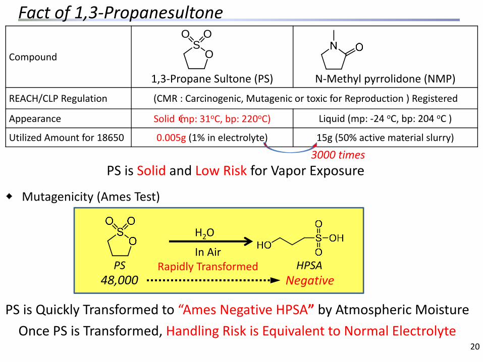
PS is Solid and Low Risk for Vapor Exposure
Compound
1,3‐Propane Sultone (PS) N‐Methyl pyrrolidone (NMP)
REACH/CLP Regulation (CMR : Carcinogenic, Mutagenic or toxic for Reproduction ) Registered
Appearance Solid(mp: 31oC, bp: 220oC) Liquid (mp: ‐24 oC, bp: 204 oC )
Utilized Amount for 18650 0.005g (1% in electrolyte) 15g (50% active material slurry)
OS
O O
Fact of 1,3‐Propanesultone
20
◆Mutagenicity (Ames Test)
48,000 Negative
H2O
PS HPSAIn Air
Rapidly Transformed
PS is Quickly Transformed to “Ames Negative HPSA” by Atmospheric MoistureOnce PS is Transformed, Handling Risk is Equivalent to Normal Electrolyte
3000 times
60
70
80
90
100
DC
-IR (R
elat
ive
Valu
e, %
)
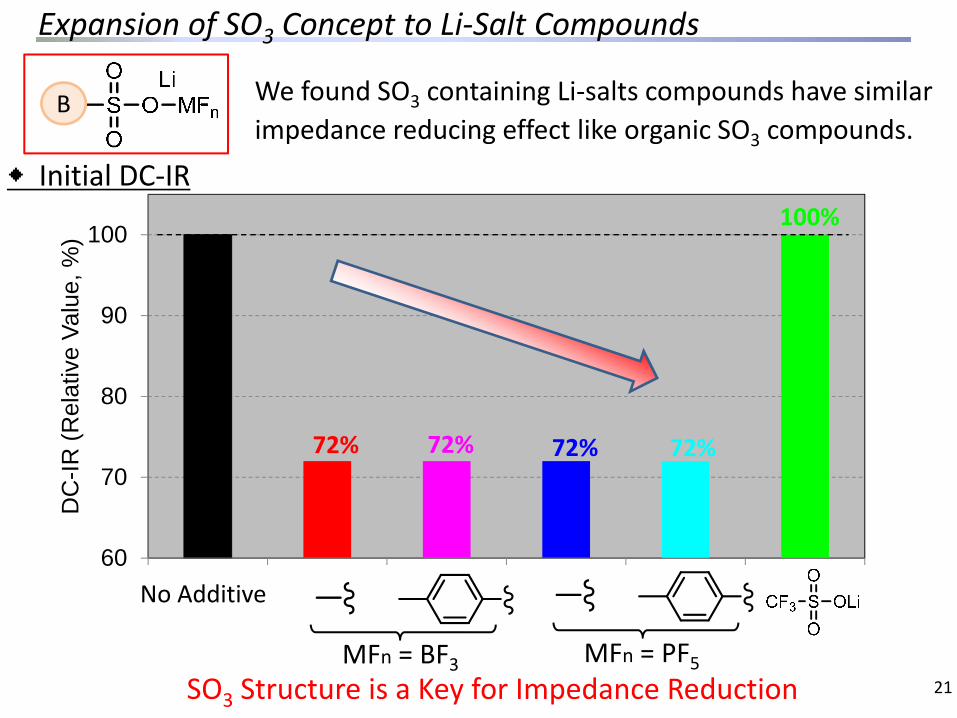
Expansion of SO3 Concept to Li‐Salt Compounds
21
72%
No Additive
72%72%
100%
72%
B
MFn = BF3 MFn = PF5
◆Initial DC‐IR
We found SO3 containing Li‐salts compounds have similar impedance reducing effect like organic SO3 compounds.
SO3 Structure is a Key for Impedance Reduction
Conclusion
22
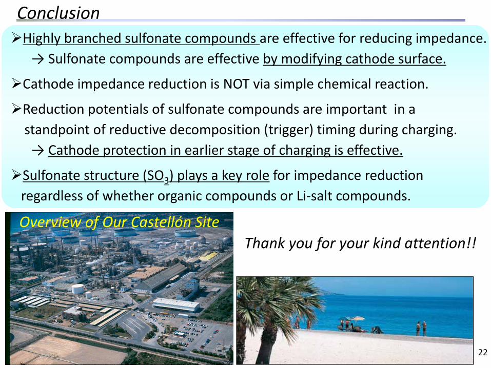
Highly branched sulfonate compounds are effective for reducing impedance.→ Sulfonate compounds are effective by modifying cathode surface.
Cathode impedance reduction is NOT via simple chemical reaction.
Reduction potentials of sulfonate compounds are important in astandpoint of reductive decomposition (trigger) timing during charging.→ Cathode protection in earlier stage of charging is effective.
Sulfonate structure (SO3) plays a key role for impedance reduction regardless of whether organic compounds or Li‐salt compounds.
Thank you for your kind attention!!Overview of Our Castellón Site