fun3d v12.4 training session 15: aeroelastic simulations
TRANSCRIPT

http://fun3d.larc.nasa.gov FUN3D Training Workshop
March 24-25, 2014 1
Bob Biedron
FUN3D v12.4 Training
Session 15: Aeroelastic Simulations

http://fun3d.larc.nasa.gov
Session Scope • What this will cover
– The two methods of aeroelastic coupling with FUN3D • Static coupling with an external structural solver (linear or nonlinear
structures) • Dynamic coupling to a self-contained, mode-based, linear
structures model • What will not be covered
– Projection of mode shapes and forces/displacements to/from CFD and FEM (covered in following session)
– Structural modeling or FEM usage • What should you already be familiar with
– Basic steady-state, time-dependent, and dynamic-mesh solver operation and control, especially as pertains to deforming meshes
– Basic flow visualization
FUN3D Training Workshop March 24-25, 2014 2

http://fun3d.larc.nasa.gov
Introduction • Background
– Aeroelastic problems of interest that can be tackled with FUN3D fall into 2 general categories • Static: structural displacement asymptotes to a fixed level;
coupling between CFD and CSD can be done infrequently - typically interested in accounting for the structural displacement on (say) cruise performance
• Dynamic: the change in aero affects the structural deformation to the extent that there is an unsteady coupling between the two; coupling between CFD and CSD must be done frequently - prediction of flutter onset is the classic example
• Compatibility – Compatible with compressible flow; mixed elements; 2D/3D
• Status – Modal (flutter) analysis fairly routine; static FEM coupling much
less so - still evolving; dynamic FEM coupling needs “framework” FUN3D Training Workshop
March 24-25, 2014 3

http://fun3d.larc.nasa.gov
Static Aeroelastics - Overview • Basic process (not a moving_grid problem - no moving_body.input )
1. Solver starts with an initial grid and solution 2. Solver reads in a new surface shape and deforms the mesh to fit 3. Solver performs the requested number of iterations, and outputs
aerodynamic loads to a file 4. Middleware (not part of the FUN3D suite), maps the aerodynamic loads
at CFD grid points onto the FEM grid 5. Structural solver computes new displacements from the airloads 6. Middleware maps structural displacements onto new surface 7. Back to step 2; repeat until converged - airloads and displacements
• Jamshid Samareh of NASA Langley provides middleware (“DDFdrive”) for this loads and deflection transfer
• In principle, the above could be applied every time step of a dynamic aeroelastic case; however, file I/O is very inefficient for this
FUN3D Training Workshop
March 24-25, 2014 4

http://fun3d.larc.nasa.gov
Static Aeroelastics - New Surface Shape • Reading of the updated surface(s) is triggered by the CLO --read_surface_from_file – File(s) read once at the start of solver execution (steady-state mode) – File root name must be of the form [project]_bodyN (for body N) – File extensions: .dat or .ddfb
• [project]_bodyN.dat ASCII Tecplot file, “FEPOINT” style • [project]_bodyN.ddfb Binary (“stream”) DDFdrive style • DDFdrive middleware supports both - .ddfb preferred
– File provides current x,y,z coordinates for each surface point plus an integer that identifies the point in the volume-mesh numbering system
– Options for this input surface file input are specified in the &massoud_output namelist (details later)
FUN3D Training Workshop March 24-25, 2014 5

http://fun3d.larc.nasa.gov
Static Aeroelastics - Aero Loads Output • Output is triggered by the CLO --write_aero_loads_to_file
– File(s) written at a user-controlled frequency – File root name of the form [project]_ddfdrive_bodyN (Nth body) – File extensions: .dat or .ddfb
• [project]_ddfdrive_bodyN.dat ASCII Tecplot file, “FEPOINT” style
• [project]_ddfdrive_bodyN.ddfb Binary (“stream”) DDFdrive style
• DDFdrive middleware supports both – File provides current Cp, Cfx, Cfy, Cfz for each surface point plus an
identifier that maps the point in the volume mesh – Options for this output surface file input are specified in the &massoud_output namelist (next)
FUN3D Training Workshop March 24-25, 2014 6

http://fun3d.larc.nasa.gov
Static Aeroelastics - &massoud_output (1/2) • The &massoud_output namelist serves several closely-related
purposes, and the name is not especially well-suited to any of them… • For static aeroelastics, it is used to
– Define the aeroelastic body(s) as a collection of boundary surfaces – Specify the format of the new surface file and the output aero loads file – Specify the frequency of the aero loads output
• Naming convention: [project]_ddfdrive_bodyN.dat • Example:
&massoud_output aero_loads_file_format = 'stream’ (default = ‘ascii’) massoud_file_format = 'stream’ (default = ‘ascii’) aero_loads_output_freq = -1 (+n…output every n steps) n_bodies = 1 nbndry(1) = 3 boundary_list(1) = '1,2,3’ /
FUN3D Training Workshop
March 24-25, 2014 7

http://fun3d.larc.nasa.gov
Static Aeroelastics - &massoud_output (2/2) • The &massoud_output namelist has additional options - rotate, translate and scale the geometry written to the aero loads file - multiply the aero coefficients by the dynamic pressure to get forces - rotate, translate and scale the geometry read from the new surface file - output aero loads on either the deflected or undeflected surfaces
FUN3D Training Workshop March 24-25, 2014 8
http://fun3d.larc.nasa.gov
Static Aeroelastics - Towards Automation • As outlined, the process is rather cumbersome, with multiple separate
runs of the flow solver, the FEM and middleware • Certainly possible to script it all together in your favorite scripting
language, running a series for steady-state FUN3D solutions in the process
• Better would be a “framework” to allow direct access of data between CFD, FEM and middleware to avoid file I/O; needed for dynamic grids
• For cases that lead to static deflections, it is possible to automate this by running FUN3D in time-accurate mode - Take very large time steps to reach static equilibrium with few steps - Run as a moving_grid case (requires moving_body.input file)
• use a consistent definition of the body in both the &massoud_output and &body_definitions namelists
- Use the CLO --aeroelastic_external_static - Provide a shell script called get_displacements_from_csd FUN3D Training Workshop
March 24-25, 2014 9

http://fun3d.larc.nasa.gov
Static Aeroelastic Coupling (4/4)
FUN3D Training Workshop March 24-25, 2014 10
Recent Application: Inflatable Decelerator - Low Speed Test

http://fun3d.larc.nasa.gov
Dynamic Aeroelastic Coupling (1/6) • For time-accurate aeroelastic modeling, FUN3D currently relies on a
modal decomposition approach – “Small” deflections are assumed, allowing the deflected shape to be
constructed as a linear combination of “mode shapes”- suitable for flutter onset, but not large deflections that occur as flutter escalates
– A nonlinear aerodynamics model is used (FUN3D), so effects of shocks and viscosity can be captured in the flow field
– Structural dynamic response is decomposed into eigenmodes of known frequency (extracted a priori from an FEM model)
– Typically only a limited set of the “important” eigenmodes is retained for dynamic aeroelastic analysis
– Middleware (e.g. DDFdrive) maps eignenmodes onto CFD surface in a one-time preprocessing step; at startup FUN3D reads these
– Aerodynamics at current time step determine the weight applied to each eigenmode; current shape is weighted sum of eigenmodes
FUN3D Training Workshop March 24-25, 2014 11

http://fun3d.larc.nasa.gov
Dynamic Aeroelastic Coupling (2/6)
FUN3D Training Workshop March 24-25, 2014 12
Vertical Scale Arbitrary
AGARD Wing 445 Mode Shapes

http://fun3d.larc.nasa.gov
Dynamic Aeroelastic Coupling (3/6) • Required command-line “option”: --aeroelastic_internal • Also need --moving_grid or moving_grid = .true in &global in fun3d.nml
• File nomenclature / format for mode shape input files – For every aeroelastic body B, each mode shape M is in a different file: [project]_bodyB_modeM.dat (.ddfb)
– Files are once again either ASCII Tecplot files (.dat) or stream DDFdrive files (.ddfb), similar to those input for static aeroelastic analysis, only now have modal amplitudes as well:
TITLE="wing-445.6 Mode 1"
VARIABLES= "x" "y" "z" "id" "xmd" "ymd" "zmd"
ZONE I= 57286 , J= 101359 , F=FEPOINT
0.109050E+01 -0.650348E+00 -0.294021E-01 17 0.000000E+00 0.000000E+00 0.869050E-01
0.691189E+00 -0.650348E+00 0.000000E+00 18 0.000000E+00 0.000000E+00 0.448300E-01
0.000000E+00 0.000000E+00 0.000000E+00 23 0.000000E+00 0.000000E+00 -0.276958E-02
• Can output a “massoud file” from FUN3D (more later) to use as a template file with x,y,z, and id to which the middleware can add modal amplitudes
FUN3D Training Workshop March 24-25, 2014 13

http://fun3d.larc.nasa.gov
Dynamic Aeroelastic Coupling (4/6) • Highlights of moving_body.input file – see manual for all the details
&body_definitions
… ! define bodies as collection of surfaces motion_driver(1) = 'aeroelastic’ mesh_movement(1) = 'deform’ / &aeroelastic_modal_data ! below, b = body #, m = mode number plot_modes = .true. ! can tecplot to verify mode shapes read correctly nmode(b) = 4 ! 4 modes for this body uinf(b) = 973.4 ! free stream velocity (ft/s) grefl(b) = 1.00 ! scale factor ft/grid unit i.e L*ref/Lref qinf(b) = 89.3 ! free stream dynamic pressure, psf freq(m,b) = 60.3135016 ! mode frequency (rad/s)
… ! skip remaining 3 modes for space! gmass(m,b) = 0.08333 ! generalized mass (nondim)
… damp(m,b) = 0.000 ! Critical damping ratio, z (nondim) (use large value
… ! 0.99999 to obtain static aeroelastic deflections) gvel0(m,b) = 0.1 ! nonzero initial velocity to kick off dynamic
… ! response; set = 0 on restart - don’t kick me twice /
FUN3D Training Workshop March 24-25, 2014 14

http://fun3d.larc.nasa.gov
Dynamic Aeroelastic Coupling (5/6) • Output of generalized force, displacement and velocity into files: aehist_bodyN_modeM.dat (ASCII Tecplot) # qinf = 8.93000E+01 uinf = 9.73400E+02 Mach = 9.00000E-01 variables = "time", "gdisp", "gvel", "gforce" zone t = "modal history for airfoil, mode 1" 0.00000E+00 0.00000E+00 1.00000E-01 0.00000E+00 3.00000E-01 2.77139E-05 9.98227E-02 -9.81176E-02 6.00000E-01 5.53548E-05 9.94742E-02 -8.60835E-02
… !
FUN3D Training Workshop March 24-25, 2014 15
Nondimensional Time
GeneralizedDisplacement
0 50 100 150 200 250 300-0.003
-0.002
-0.001
0
0.001
0.002
0.003
Mode 1Mode 2Mode 3Mode 4
Mode 1 Grows In Response To Perturbation
Typical plot to assess dynamic
response to disturbance (initial
perturbation in gvel)

http://fun3d.larc.nasa.gov
Aeroelastic Analysis of AGARD 445.6 Wing
FUN3D Training Workshop March 24-25, 2014 16
Results Courtesy Pawel Chwalowski, Aeroelasticity Branch, NASA Langley
http://fun3d.larc.nasa.gov
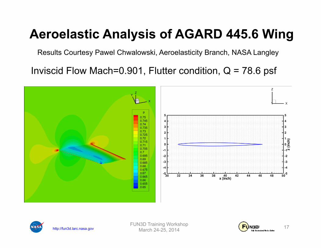
Aeroelastic Analysis of AGARD 445.6 Wing
FUN3D Training Workshop March 24-25, 2014 17
Results Courtesy Pawel Chwalowski, Aeroelasticity Branch, NASA Langley
Inviscid Flow Mach=0.901, Flutter condition, Q = 78.6 psf

http://fun3d.larc.nasa.gov
“Bootstrapping” Aeroelastic Problems (1/2) • All aeroelastic problems, (except highly-specialized rotorcraft problems),
utilize either an ASCII Tecplot (.dat) or stream DDFdrive (.ddfb) file to define either a new surface or a set of mode shapes - These files need to have the correct surface points for the surface/
body in question, plus an integer tag for each point that maps the surface point in the corresponding volume grid.
- The tag must be preserved throughout any external manipulation of these files (when shape is updated or modes mapped onto surface)
• How does one generate this surface info? - Use the CLO --write_massoud_file and &massoud_output
namelist input during an initial run (perhaps when generating a rigid steady-state solution)
- This will generate a [project]_massoud_bodyN.(dat or ddfb) file for input to DDFdrive or as a template for some other middleware.
- Rename as needed (e.g. [project]_bodyN for static AE)
FUN3D Training Workshop March 24-25, 2014 18

http://fun3d.larc.nasa.gov
“Bootstrapping” Aeroelastic Problems (2/2) • Example
&massoud_output n_bodies = 2 nbndry(1) = 3 boundary_list(1) = ‘5 7 9’ nbndry(2) = 2 boundary_list(2) = ‘3 4’ /
• Also need CLO --write_massoud_file
FUN3D Training Workshop March 24-25, 2014 19
http://fun3d.larc.nasa.gov
Additional Considerations • Be especially careful with dimensions and coordinate systems since at
one point or another exchange must be done between CFD and FEM - need to ensure consistency!
• Note that frequencies increase in the higher modes; choose time steps accordingly
FUN3D Training Workshop March 24-25, 2014 20

http://fun3d.larc.nasa.gov
List of Key Input/Output Files • Beyond basics like fun3d.nml, [project]_hist.tec, etc.: • Input
– moving_body.input – [project]_body1.dat (.ddfb) (external FEM / static AE) – [project]_bodyB_modeM.dat (.ddfb) (modal structures)
• Output – aehist_bodyB_modeM.dat (modal structures only) – [project]_ddfdrive_bndryN.dat (with CLO)
FUN3D Training Workshop March 24-25, 2014 21