full scale experimental testing of retrofitting techniques ... · full scale experimental testing...
TRANSCRIPT

Full scale experimental testing of retrofitting techniques in Portuguese “Pombalino” traditional timber frame
walls
Elisa Poletti, Graça Vasconcelos, Marco Jorge
ISISE, Department of Civil Engineering, University of Minho, Campus de Azurém, Guimarães,
Portugal
Corresponding author: Elisa Poletti
Email: [email protected]
Abstract
Traditional timber frame walls are constructive elements representative of different timber frame
buildings that are well known as one of the most efficient seismic resistant structures in the world.
Timber frame walls were also used in the reconstruction of buildings of the old town of Lisbon after
the earthquake of 1755 aiming at improving their seismic global behaviour. As it is important to
preserve these structures, a better knowledge about their behaviour under seismic actions is
important and can give some indications about possible retrofitting techniques to be used to
improve the seismic performance. Due to the great rehabilitation effort currently carried out in
many countries, a better understanding of retrofitting techniques is also needed. Therefore, this
paper aims at providing a study on possible retrofitting techniques adopting traditional solutions
such as bolts and steel plates. Static cyclic tests have been performed on retrofitted traditional
timber frame walls in order to study their seismic performance. The experimental results showed
the overall good seismic performance of steel plates and the more ductile behaviour of retrofitted
timber frame walls with bolts
Keywords: timber frame wall, cyclic test, retrofitting, steel plates, bolts, stiffness, energy
dissipation

1 Introduction
In the past centuries all sort of natural materials have been used to build walls, such as mud, earth,
straw, clay, cork and wood. Timber has often been associated to masonry as a complementary
material to bind masonry. Timber frame walls combine these natural materials, creating a
traditional structural element relatively cheap and which can be built with the materials locally
available.
Timber frame walls are often adopted in seismic regions as shear walls, in order to resist to
horizontal seismic actions. An example of this, is the adoption of timber frame walls in the
reconstruction of vernacular buildings in Haiti [Vieux-Champagne, 2012], after the earthquake of
January 2010. The particular geometry of the walls, with St. Andrew’s crosses, contributes to the
capacity to dissipate the energy generated by the earthquake motion. Besides, the timber structure
that acts as a skeleton of the building does not encounter severe damages during the earthquake
[Mascarenhas, 2004; Gülhan and Güney, 2000].
The origin of timber frame structures probably goes back to the Roman Empire, with what is
called Opus Craticium by Vitruvius [Langenbach, 2007]. But examples were also found in previous
cultures, such as in the Minoan palaces in Knossos and Crete [Tsakanika-Theohari, 2006], where,
according to historians, timber elements were used to reinforce masonry [Tampone, 1996]. Timber
frame constructions later spread not only throughout Europe, such as Portugal (edifícios
pombalinos), Italy (casa baraccata), Germany (fachwerk), Greece, France (colombages or pan de
bois), Scandinavia, United Kingdom (half-timber), Spain (entramados) etc., but also in India (dhaji-
dewari), Turkey (himis and bagdadi), Peru (quincha), USA (balloon frame in Chicago) and Haiti
(Gingerbread houses) [Langenbach, 2007; Cóias, 2007]. In each country different geometries for
the traditional timber frame walls were used, but the common idea is that the timber frame can
confine masonry, providing a better resistance to horizontal loads.
In Portugal these structures were adopted after the devastating earthquake that hit Lisbon in 1755
for the construction of residential and commercial buildings, known as Pombalino buildings. These
buildings are characterized by external masonry walls and an internal timber structure, named
gaiola (cage), which is a three-dimensional braced timber structure. The gaiola consists of
horizontal and vertical elements and diagonal bracing members, forming the typical X of St.
Andrew’s crosses. The internal walls of the gaiola (frontal walls) may have different geometries in
terms of cell dimensions and number of elements. The timber elements are notched together or
connected by nails or metal ties. Traditional connections used for the timber elements varied
significantly in the buildings: the most common ones were mortise and tenon, half-lap and dovetail
connections.
Since these structures constitute an important historical heritage in many city centres in the world,
their conservation is of essential importance and many restoration works are being done without
having accurate knowledge on the behaviour of these structures before and after the application of
the strengthening, which sometimes modifies significantly the original structure. Numerous
Pombalino buildings in Lisbon have been retrofitted using FRP sheets in the connections of the
frontal walls, creating a star-shaped strengthening [Cóias, 2007], or damping systems linked to
frontal walls and to the outer masonry walls through injected anchors and providing additional
bracing [Cóias, 2007]. In spite of this, little information is available on the actual behaviour of the
strengthened walls under seismic actions. Cruz et al. [2001] performed diagonal tests on reduced
scale wallets strengthened with Glass Fiber Reinforced Polymer (GFRP) rods and Glass Fiber
Fabric (GFF) sheets. The walls were retrofitted embedding two GFRP bars in the outer timber
members and GFF sheets were glued to the timber elements at the central connections. More
relevant information is available on retrofitting techniques for traditional timber connections
[Branco, 2008; Parisi and Piazza, 2002], which are also of great importance for the strengthening
of traditional walls, since strengthening of these walls is almost reduced to the strengthening of the
connections. Branco [2008] studied the cyclic behaviour of traditional timber connections (bird’s
mouth connections) and appropriate retrofitting solutions, which consisted of metal stirrups, internal
bolts, binding strips and tension ties, being all considered as traditional solutions.
Higher amount of research is available on modern timber frame walls [Lam et al., 1997; Toothman,
2003], but for these walls strengthening is not usually considered. An improvement of their seismic
behaviour is usually achieved through the adoption of different sheathing or through an alternative

disposition of the frame [Varoglu et al., 2006]. Premrov et al. [2004] studied timber frame walls
coated with carbon fibre-reinforced polymers (CFRP) strengthened fibre-plaster boards.
Following an experimental research on the evaluation of the in-plane cyclic testing of timber frame
walls characteristic of Pombalino buildings, it was decided to strengthen the walls through two
traditional techniques in order to assess the improvements on the cyclic performance, namely bolts
and steel plates. The main aim of the work presented herein is to contribute to the state of the art
and attain a better insight on the mechanical behaviour of these structural elements under
horizontal loads with different retrofitting solutions.
2 Experimental campaign performed on timber frame walls
The objective of this work is to study the seismic performance of the Portuguese traditional
timber frame walls, characteristic of Pombalino buildings built in the reconstruction of the
old town after the great earthquake that hit Lisbon in 1755. The idea is that timber frame
walls can improve considerably the seismic performance by contributing to the shear
resistance of the building submitted to lateral loads. With this goal in mind, an intensive
experimental program was designed based on static cyclic tests on real scale walls. Static cyclic
tests are able to simulate, in a simplified manner, the seismic loads to which a shear wall is
subjected during an earthquake [Tomaževič et al., 1996].
2.1 Wall specimens and types of retrofitting
The two adopted retrofitting techniques (bolts and steel plates) were applied on the previously
unreinforced timber frame walls tested under cyclic loading [Poletti, 2013]. The tested walls were
then repaired and retrofitted with distinct retrofitting techniques.
The sectional dimensions of all the members of the timber frame and the size of the cells were
decided according to the dimensions of existing buildings found in literature [Mascarenhas, 2004].
The top and bottom beams have a cross section of 16×12cm2 and all the other members have a
cross section of 8×12cm2. The total width of the wall is 2.42m and the total height 2.36m, resulting

in a height to length ratio of approximately 1.0, even if in some cases this ratio can be higher. The
cells are 86cm wide and 84cm high.
The connections of the main frame and between each two diagonal are all half-lap connections, ,
whereas the connection between the main frame and the diagonals is made by contact (Fig. 1). In
all of the connections a nail was inserted.
Fig. 1 Timber frame with detail of the type of connections adopted
The original Pombalino buildings presented timber frame walls filled with masonry (either
brick or rubble), and thus part of the walls were filled with brick masonry, with a pattern
suggested by a Portuguese company specialized in rehabilitation. The masonry pattern consists of
double leaf masonry with transversal series of bricks every two rows of horizontal double leaf
masonry, as detailed in Fig. 2. Some specimens were kept without infill in order to assess the
influence of its presence on the timber frame [Poletti, 2013].
Fig. 2 Timber frame walls: masonry pattern adopted for infill walls
For the strengthening, two distinct types of traditional techniques were adopted, namely: (1) bolts
and (2) steel plates. The selection of these techniques was based on the damages found in the
unstrengthen walls [Poletti, 2013]. Both techniques use steel as material and are considered to be

fast to be applied and removable (reversible), which represents an advantage, mainly concerning
rehabilitation of cultural heritage structures. The retrofitting was applied to the connections, as
the damaged observed for both wall typologies were concentrated at the connections.
The design of the retrofitting techniques was based on of the following parameters; (1) cross-
sectional dimensions of timber elements involved, keeping in mind limitations on the minimum
distances from the borders for bolts and screws [Eurocode 5, 2004]; (2) presence of knots or of
pre-existing drying fissures, since they could create a preferential failure path. For this reason,
visual inspection is suggested before strengthening the walls; (3) tensile strength and ductility of
steel plates. It should be ensured that the plates have an adequate capacity to deform and that
failure by tearing of the plate in tension does not occur, meaning that the tensile strength of the
plate has to be greater than that of the component material.
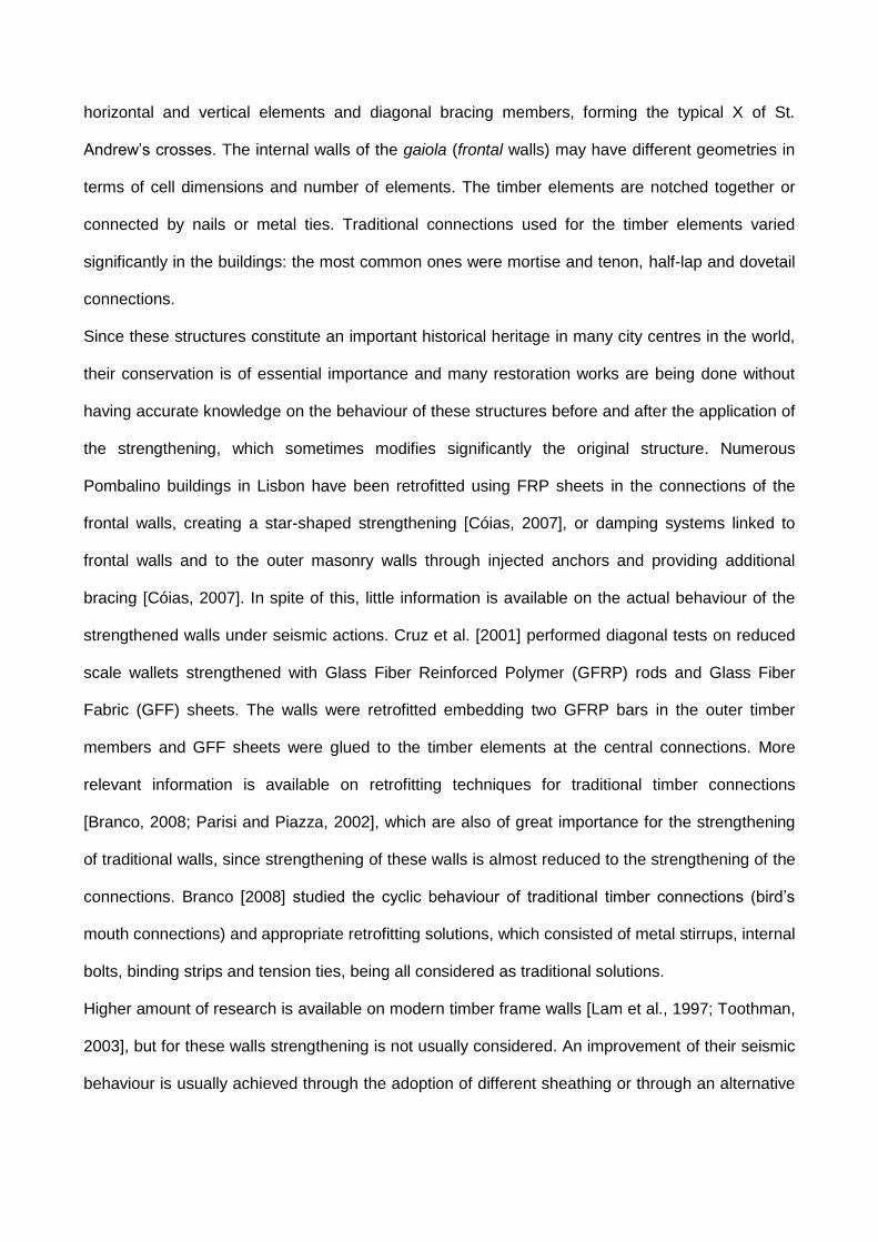
For the first retrofitting technique one bolt was added in each half-lap connection of the main
frame, see Fig. 3, aiming at tying together the two elements of the half-lap connection, namely
vertical post and horizontal beam. The choice of using one bolt for each connection was
based on the spacing limits provided by Eurocode 5 [2004] concerning edge and end
distances, both in terms of position and in terms of bolt diameter. The bolts pass through the
thickness of the wall. The selection of these connections was based on the trend for the out-of-
plane detachment of the posts from the beam exhibited by unreinforced walls, especially at the
bottom connections [Poletti, 2013], reducing thus the efficiency of the connection. The bolts had a
diameter of 10mm and a total length of 160mm and were of the class 8.8 steel fasteners. They
were inserted in pre-drilled holes, according to recommendations of Eurocode 5 [2004]. Washers
were used to better distribute the stresses.
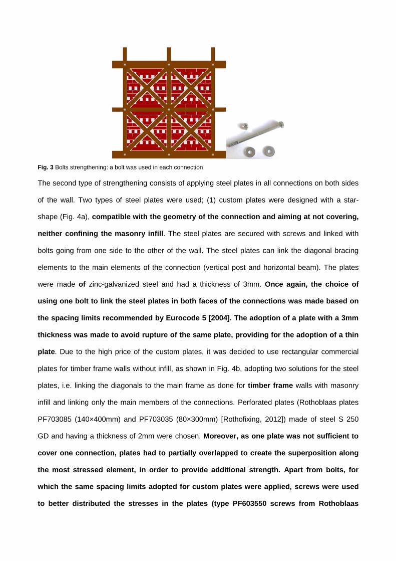
Fig. 3 Bolts strengthening: a bolt was used in each connection
The second type of strengthening consists of applying steel plates in all connections on both sides
of the wall. Two types of steel plates were used; (1) custom plates were designed with a star-
shape (Fig. 4a), compatible with the geometry of the connection and aiming at not covering,
neither confining the masonry infill. The steel plates are secured with screws and linked with
bolts going from one side to the other of the wall. The steel plates can link the diagonal bracing
elements to the main elements of the connection (vertical post and horizontal beam). The plates
were made of zinc-galvanized steel and had a thickness of 3mm. Once again, the choice of
using one bolt to link the steel plates in both faces of the connections was made based on
the spacing limits recommended by Eurocode 5 [2004]. The adoption of a plate with a 3mm
thickness was made to avoid rupture of the same plate, providing for the adoption of a thin
plate. Due to the high price of the custom plates, it was decided to use rectangular commercial
plates for timber frame walls without infill, as shown in Fig. 4b, adopting two solutions for the steel
plates, i.e. linking the diagonals to the main frame as done for timber frame walls with masonry
infill and linking only the main members of the connections. Perforated plates (Rothoblaas plates
PF703085 (140×400mm) and PF703035 (80×300mm) [Rothofixing, 2012]) made of steel S 250
GD and having a thickness of 2mm were chosen. Moreover, as one plate was not sufficient to
cover one connection, plates had to partially overlapped to create the superposition along
the most stressed element, in order to provide additional strength. Apart from bolts, for
which the same spacing limits adopted for custom plates were applied, screws were used
to better distributed the stresses in the plates (type PF603550 screws from Rothoblaas

[Rothofixing, 2012]), having a diameter of 5mm and a length of 50mm. The screws present a
round head with a cylindrical underhead and are especially designed to be used with these
steel plates. The number of screws adopted depended on recommendations of Eurocode 5
[2004]. Both types of steel plates require low technical equipment and non-specialized
workmanship.
(a) (b)
Fig. 4 Strengthening with steel plates: (a) custom plates for timber frame walls with masonry infill; (b) commercial plates for timber frame walls without infill
It should be stressed that both retrofitting techniques were applied after the specimens were
previously submitted to lateral cyclic tests, meaning that the retrofitting was made for certain levels
of damage induced in the walls. This situation simulates the retrofitting that can be made after the
occurrence of an earthquake.
2.2 Material properties
In order to be able to better assess the behaviour of the walls during the cyclic tests, it is important
to have an idea about the strength and mechanical behaviour of the materials, namely wood,
mortar, masonry infill and steel adopted.
Wood, mortar and masonry had already been characterized for the previous tests [Poletti, 2013]. A
summary of the results on the mechanical characteristics of the materials (wood, bricks, mortar
and masonry) is presented in Table 1. Considering the materials used for strengthening, only steel
plates were characterized in tension according to standard BS EN 10002-1 [2001]. It was assumed
that steel bolts followed the requirements of steel class 8.8.

Table 1 Values of mechanical characteristics for materials used
Material Compressive
strength [MPa]
Bending strength
[MPa]
Modulus of elasticity [GPa]
Standard
Wood 38,18 (// to the grain) 47,84 10,82 (global in bending) 12,02 (local in bending) 11,04 (in compression)
EN 408 [2003]
Mortar 4,01 1,58 - EN 1015-11
[1999]
Bricks 34,5 - - EN 772-1
[2000]
Masonry 7,73 - 4,55 EN 1052-1
[1999]
Custom steel plates made of zinc-galvanized steel present an ultimate strength of 321.4MPa
(c.o.v. 1.62%), with a percentage of elongation after fracture of 41.7% (c.o.v. 5.54%). The
commercial rectangular steel plates made of S250GD steel present an ultimate strength of
477.2MPa (c.o.v. 1.85%), with a percentage of elongation after fracture of 3.5% (c.o.v. 14.29%).
The difference in the elongation capacity of both types of plates is attributed to the holes of
commercial plates, which constituted preferential points of failure in the plate, acting also in
detriment of its deformation.
2.3 Test setup and instrumentation
The cyclic tests were carried out using the setup illustrated in Fig. 5. The application of the vertical
load was made by means of vertical hydraulic actuators applied directly on the three posts. The
actuators were connected to hinges welded in the bottom steel beam through steel rods, thus
following the horizontal movement of the wall.
The horizontal displacement was applied to the top timber beam through a hydraulic servo-actuator
with a maximum capacity in terms of displacement and load of 200mm and 250kN respectively.
The out-of-plane displacements were prevented by a guide created in the upper beam through
lateral steel rollers. For a detailed description of the test setup, see Poletti [2013].

Fig. 5 Test setup used for cyclic tests
All of the walls were instrumented with linear voltage displacement transducers (LVDTs), placed in
strategic positions to capture the global and local deformations of the walls, see Fig. 6. The
horizontal displacements at the top (through TOP LVDT and control LVDT) and mid height beam
(through MR and ML LVDTs) were measured on both sides of the wall. The vertical uplift of the
three bottom connections were monitored through LVDTs BR, BM and BL.
Fig. 6 Instrumentation in walls tested
The displacement in the diagonals is measured with LDVTS DF and DB at the front and back of
the wall, in order to evaluate the effect of the compressive and tensile cycles as well as differences
in both sides of the wall. The rest of the LVDTs were positioned strategically to measure the local
opening of the connections.
In order to understand the efficiency of the strengthening materials and their mechanical behaviour
during the tests, strain gauges were used in strategic places on the steel plates.
142
224
24
2001002
00
300
236
242
125
BRBL BM
+ - +-
DF DB
MRML MLMR
TOP TOP
BH BH
BV
DV1DH1DH2
CR CM CL
FRONT BACK
DBLDBR
DTL
DV2
DTR
CONTROL CONTROL

2.4 Vertical loading, cyclic procedure and number of specimens
The pre-compression loads applied were the same ones used in the unreinforced tests [Poletti,
2013], namely 25kN/post and 50kN/post, corresponding to the load calculated based on a building
of three floors above the wall (4 floors in total) [Eurocode 1, 2002], and to an additional vertical
load level respectively. The application of different vertical load levels aimed at assessing the
influence of this variable in the lateral response, considering a possible change in use of the
structure.
The cyclic procedure used for the retrofitted tests was the same one adopted for the previous tests
[Poletti, 2013], following the recommendation of standard ISO DIS 21581 [2009]. In order to better
capture the highly non-linear behaviour of the walls, additional steps were added in the procedure,
considering an increment in the applied displacement of 10% (see Fig. 7).
Fig. 7 Test procedure used in the experimental campaign of timber shear walls
In total, eight strengthened walls were tested, distributed in two distinct groups, see Table 2,
according to the type of infill: (1) walls named as RIW with brick masonry infill; (2) walls named as
RTW in which no infill was considered. The number 25 or 50 used in each designation is
associated to the vertical load applied. The type of strengthening is given by the last letter and is
divided in three groups: (1) bolts (letter B); (2) custom steel plates (letter P); (3) commercial steel
plates (letters P_M).
To make the comparison with unreinforced walls easier, UIW designates unreinforced timber frame
with masonry infill and UTW unreinforced timber frame walls, with the suffix 25 or 50 indicating the
vertical load level. The decision to test only one specimen was based on the scarce availability of

specimens and on the results obtained in the unreinforced tests, given the low variation in terms of
lateral resistance and deformation.
Table 2 Typology of the specimens tested under cyclic loading
Specimen
Vertical load Type of infill Type of strengthening
25kN/post 50kN/post Brick
masonry No
infill Bolts
Custom steel
plates
Commercial steel plates
RIW25_B
RIW50_B
RIW25_P
RTW25_P
RTW25_P_M
RIW50_P
RTW50_P
RTW50_P_M
3 Analysis of test results
Cyclic test results performed on timber frame walls with and without brick masonry infill are
here presented in this section and a discussion on the performance of the retrofitting techniques
adopted is reported. The presentation and discussion of the results can be divided into three parts,
namely: (1) discussion of the typical force-displacements hysteresis diagrams; (2) discussion of the
main deformation features and typical failure modes; (3) assessment of seismic performance
indicators.
3.1 Typical hysteretic diagrams
In this section the hysteretic diagrams of the retrofitted walls tested are presented, together with
the vertical uplift of the bottom connections, in order to better understand the behaviour of the
walls. In the unreinforced condition the walls had a strong flexural behaviour when tested with the
lower vertical pre-compression load, characterized by rocking of the walls and consequent uplifting
of the vertical posts. The walls tested with the higher pre-compression load exhibited a composite
flexural-shear resisting mechanism [Poletti, 2013]. The retrofitting techniques adopted aimed at
improving the performance of the walls under cyclic loading by limiting the rocking mechanism and
improving their resistance, ductility and energy dissipation.

Comparing the hysteretic behaviour of the walls strengthened with bolts and the corresponding
unreinforced timber frame walls with masonry infill, it is observed that there is no great gain in
terms of ultimate capacity and stiffness. In fact, for the lower vertical load level, the gain in terms of
maximum load was of 23.7%, whereas for the higher vertical load level it lost 5%. In terms of
ultimate displacement, the walls gained 5.7% and 0.2% respectively (Fig. 8). The very low
effectiveness of bolts as a retrofitting technique in timber frame walls can be attributed to the
predominant flexural behaviour. In fact, bolts are not completely efficient in resisting the tensile
stresses induced by cyclic loading at the bottom connections, being possible to observe practically
the same damage patterns, i.e., tearing off of the beam-post half-lap connections.
In spite of this, for both load cases, the shape of the hysteretic loops experiences some changes.
The plateau caused by the uplifting and recovering of the vertical post from the bottom beam
[Poletti, 2013] is still present, but it is less pronounced and the unloading branch of the cycles is
smoother. The vertical uplifting of the posts decreased of approximately 40% for both load cases,
resulting from the lower predominance of the flexural resistant mechanism and from the
contribution of a certain shear resistant component. Even in a reduced scale, the bolts contributed
to the resistance to tensile forces developing in the bottom half-lap connections, and ensured a
more remarkable post-peak behaviour enabling the connections to work until failure, contrarily to
unreinforced walls, where after a certain lateral drift no contact was observed between the post
and the bottom beam.
Fig. 8 Hysteretic diagrams for walls strengthened with bolts, higher pre-compression load

The comparison between the hysteresis diagrams found in unreinforced walls and after retrofitting
with steel plates can be made through the analysis of Fig. 9, where results are shown for the walls
tested with the higher vertical pre-compression. Walls retrofitted with steel plates experienced a
similar behaviour independently on the vertical load level. For both timber frame walls with
masonry infill, an important increase in terms of load capacity and stiffness was recorded: the
maximum lateral load increased by 147% for the lower vertical load and by 60.4% for the higher
vertical load. The initial stiffness of the walls increased by 30% when compared to the unreinforced
solution for the lower vertical load level and by 14% for the higher vertical load level. The
displacement imposed to the walls does not correspond to its maximum displacement capacity as
it was not possible to obtain the complete failure mode of the walls, even if, due to the high levels
of lateral load reached, the walls exhibited some out-of-plane displacement, reaching values of
6mm at mid height of the wall. The high stiffening effect of custom steel plates, linking the main
elements of the connection (post and beam) to the diagonals, together with the slenderness of the
wall led to this out-of-plane component, even if it was considered minimal. The ultimate state would
be achieved if further lateral displacements were applied.
For this type of strengthening, the values of initial lateral stiffness are comparable for the two
vertical load levels, meaning that for such a strong retrofitting technique, the effect on the amount
of vertical load becomes secondary.
(a) (b)

(c)
Fig. 9 Strengthening with steel plates: (a) infill timber frame wall, higher vertical load; (b) timber frame wall with plates
linking the diagonals, higher vertical load; (c) timber frame wall with plates linking main elements only, higher vertical load.
The lateral cyclic behaviour obtained for timber frame walls retrofitted with commercial plates
linking the main members (post and beams) with the diagonals is shown in Fig. 9b.. Notice that the
higher number of fasteners in a connection should be favourable from the point of view of ductility
[EC8, 2004]. From the analysis of results, it is observed that this retrofitting configuration led to
considerable out-of-plane behaviour, mainly in the positive direction, resulting in the instability of
measurements of the in-plane response for both pre-compression levels, even though the walls
were restrained against out-of-plane movements with an additional testing device applied at
the top beam. This out-of-plane deformation was mainly due to the stiffening of the walls and to
the remarkable increase of lateral strength resulting in higher levels of compressive stresses
conducted by the diagonal elements, promoting the development of second-order effects. From the
results obtained, it appears that this type of retrofitting is too stiff and not ductile enough for
timber frame walls without infill, increasing significantly the lateral resistance (over 200% for the
lower vertical load level and 97% for the higher vertical load when compared to the equivalent
unreinforced wall) and the stiffness of the walls (77% for the lower vertical load and 50% for the
higher one). This configuration adopted for the steel plates prevented severely the movement of
the diagonals, which is a deformability feature of the unreinforced timber frame walls [Poletti,
2013].
Therefore, in order to avoid this behaviour it was decided to adopt the same type of strengthening
but without linking the diagonals, i.e. the steel plates were in the same position as in the previous
tests, but the bolts and screws linked only the main members (posts and beams) allowing the free

detachment of the diagonals, keeping the deformation to the diagonals free. This solution allowed
the walls to gain significantly both in terms of stiffness and load capacity, without compromising the
displacement capacity (see Fig.9c). In fact, in terms of maximum load, the walls gained 183% and
35% for the lower and higher pre-compression load respectively and experienced a minimal
reduction of 5% and 3.5% in terms of ultimate displacement respectively. On the other hand, this
retrofitting solution led to remarkable pinching in the timber walls. Similarly to the retrofitting with
custom plates, the vertical load has only marginal influence in terms of maximum load, even if it
influences the initial stiffness, being higher for the higher vertical pre-compression. This solution is
therefore more appropriate for timber frame walls, since its stiffening effect is not overwhelming.
Comparing the two retrofitting solutions, bolts were able to improve the overall behaviour of the
wall in terms of deformation capacity and post-peak behaviour, but it is not relevant in the increase
on the lateral strength. On the other hand, the appropriate steel plates configuration is able to
guarantee a better seismic response of the walls both in terms of stiffness and load capacity.
3.2 Deformational features of the walls
Besides the uplift of the posts analysed previously, some other deformational features are also
here analysed in order to better understand the lateral behaviour of the distinct walls.
From the displacement measured on the diagonals (Fig. 10) it is possible to understand the
stiffening effect of each retrofitting technique. For all walls, the diagonals deformed moderately until
failure (diagonal displacements in the order of 10 to 15mm), similarly to what happened in
unreinforced timber frame with masonry infill [Poletti, 2013]. For the stiffer retrofitting solution (steel
plates linking the diagonals to the main frame), the deformation of the wall was moderate even
after failure, achieving values up to approximately 30mm (Fig. 10a). Higher values of diagonals
movement are reached only if there is complete failure of one element.

(a) (b)
Fig. 10 Diagonal displacement in timber frame walls retrofitted with steel plates for higher vertical load level: (a) with
masonry infill; (b) without masonry infill (only main elements are connected with the steel plates).
For the less stiffening solutions (bolts and steel plates not linking the diagonals), a similar
behaviour was observed. After failure of the central connection (sometimes the lateral one of the
central beam also failed), an increase in the crack opening led to higher elongations of the
diagonals, reaching values of about 45mm for bolts strengthening and 50mm for steel plates (Fig.
10b).
The same conclusions can be drawn from the analysis of the horizontal displacement at mid height
of the wall (Fig. 11). For all walls where the diagonals were not linked to the main elements (i.e.
bolts and second configuration of steel plates), the two sides of the walls experienced similar
displacements up to failure, and an almost displacement linear profile was obtained. After failure,
the displacements at mid height increased significantly and became asymmetrical when comparing
both sides of the wall (Fig. 11a). In fact, with the shear crack opening at the central connection it is
not possible to have a full displacement transfer between border posts.
(a) (b)
Fig. 11 Displacement at mid height: (a) wall RTW50_P_M; (b) wall RIW50_P

For the stiffer solutions (Fig. 11b), the displacement on the two sides of the wall was similar, with a
small tendency to deform more on one side after failure occurred. The displacements recorded
were generally higher than half of the displacement applied to the top of the wall, meaning that the
deformation of the walls does not result exclusively from the rotation of the walls but results from
the deformation associated to flexure and shear of the wall.
The distinct deformation of the walls retrofitted with different configuration for the steel plates can
be also observed in the openings recorded in other connections, see Fig. 12. The failure in the
diagonal half-lap connection of wall RTW50_P (Fig. 12a) led to an opening of approximately 20mm
(either in infill or timber frame walls). Instead, the displacement recorded at the half-lap
connections of the main frame was minimal, not reaching 5mm, confirming the more rigid response
of the wall.
The central connection of wall RTW50_P_M (Fig. 12b) experienced low openings until failure (up
to 4mm) similarly to what was experienced in unreinforced timber frame walls [Poletti, 2013]. After
failure the opening of the connection increased progressively, reaching an opening of 47mm.
Nonetheless, the connection was still able to work since the steel plates kept the timber elements
together. In order to see the damage level to which the wall had been subjected, it was necessary
to take out the steel plates, since no damage was visible otherwise. A similar behaviour was
observed in walls retrofitted with bolts, which experienced even higher openings (over 50mm),
since the contribution of the steel plates was not present.
(a) (b)
Fig. 12 Opening of connections: (a) diagonal opening of half-lap connection in wall RTW50_P; (b) central middle
connection of wall RTW50_P_M
To understand the efficiency of the retrofitting techniques adopted, in particular to understand the
level of effectiveness, strain gauges were applied to the steel elements used in the reinforcement
techniques. In general, strain gauges applied to the steel plates recorded small deformations in the
plates, usually under 1.5‰ (Fig. 13). The main deformation in the steel plates consisted of the
ovalization of the holes where the bolts were inserted and buckling of the plates which could not be
prevented by the screws, since they failed in shear. This local deformation was responsible for the
higher pinching behaviour found when steel plates were used.
Fig. 13 Strain gauges recording at steel plate in central connection of wall RTW25_P_M
3.3 Typical damage patterns
The distinct deformational features of the walls discussed previously resulted from distinct damage
patterns exhibited by the different walls. The typology of strengthening is particularly relevant in the
damage patterns when timber frame walls with and without infill are compared.
Walls retrofitted with bolts exhibited severe damages for both vertical load levels. The walls
experienced damages in the central connections until their failure. The nailed diagonals detached
from the main frame. The central beam tore off (Fig. 14a) in tension and the central post crushed
due to the shear induced by the diagonals, similarly to what happened in the unreinforced tests
[Poletti, 2013].
As already mentioned, in case of walls retrofitted with steel plates the damages observed were
similar for all walls and they consisted on: (1) failure of the half-lap connection linking two diagonal

members when steel plates linked the diagonals to the main frame; (2) failure of the central middle
connection when the diagonals were not linked to the main frame through the steel plates.
The failure of the half-lap connection of the diagonal elements occurred in all specimens,
independently on the type of plate, because this type of retrofitting stiffened excessively the
connections, not allowing free movement to the bracing elements. The strong retrofitting of the
post-beam half-lap connections in combination with the increase on the stresses carried by the
diagonal bars resulted in the failure of the weakest zones of the wall, which were the half-lap
connection of the diagonals. Notice that no damages were observed in the main wood members of
the connection. An example of this type of failure is given in Fig. 14b for RIW50_P. An ovalization
of the holes for the bolts in the diagonals was also observed, since these elements were
particularly stressed.
When the diagonals are free to move, the failure occurs in the main members of the frame. In both
specimens tested with this retrofitting scheme, failure occurred in the central middle connection
(Fig. 14c) due to the shear action imposed by the diagonal elements. For the higher vertical load,
the failure propagated along the horizontal beam in alignment with the bolt, due to the presence of
a knot. From Fig. 14c it is seen that the rotation of the steel plate during the test is clearly visible.
The rotation was associated to the non-deformation of the steel plate and to the shear failure of the
screws resulting from their shear resisting mechanism against this rotation.
(a) (b)

(c)
Fig. 14 Typical damages in walls: (a) tearing off of central beam RIW25_B; (b) failure of half-lap connection in bottom cell
in RIW50_P; (c) failure of central connection in RTW50_P_M
In all timber frame walls with masonry infill, damage was also observed in the brick masonry infill,
with cracking mostly developed at the unit-mortar interface, detachment of masonry from the main
frame and out-of-plane rotation of the masonry blocks, see Fig. 15. The damages were
concentrated at the bottom half of the wall, as happened in unreinforced walls [Poletti, 2013], but
they propagated even in the upper part of the walls, particularly for walls strengthened with bolts
(Fig. 15a). In case of timber frame walls with masonry infill retrofitted with steel plates the
complete detachment of some masonry blocks was observed (Fig. 15b).
(a) (b)
Fig. 15 Crack pattern in infill timber frame walls: (a) bolts strengthening; (b) strengthening with steel plates
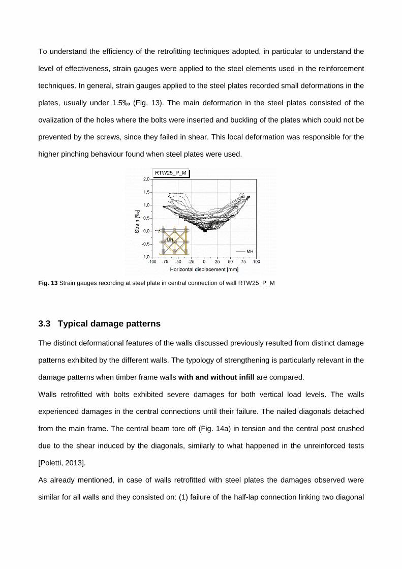
The steel plates, both custom and commercial, did not exhibit significant deformations during tests.
Only the plates located at the bottom connections tended to buckle (Fig. 16a) due to the elongation
and compression during the test to which they were subjected. However, the holes accommodating
the bolts were ovalized (Fig. 16b) due to bolt deformation during the test. In fact, all bolts used in
the bottom and central connections, either as a standalone solution or together with steel plates,
presented important deformations. It has to be noticed that for all bolts the deformation happens at
a length of approximately 6cm, which is exactly the thickness of half connection, i.e. where the two
elements are in contact. When analysing the connections after demolishing the walls, the holes in
the timber elements of the posts, i.e. the elements that were uplifting, presented severe ovalization.
(a) (b)
Fig. 16 Deformations in strengthening elements: (a) buckling of bottom steel plates; (b) damages in commercial steel
plate used in wall RTW50_P_M in the central connection with ovalized holes and deformed bolts.
3.4 Seismic performance
In the seismic design of new timber structures or in the rehabilitation of existing structures,
including historic timber frame walls, the study of the seismic performance is of paramount
importance. Since the seismic response of timber structures is very complex and time dependant,
a better understating of the factors governing the problem is important for a safe and economical
seismic design or for the adoption of the most adequate retrofitting measures. Parameters such as
ductility, energy dissipation, overall cyclic stiffness, equivalent viscous damping ratio and lateral
drifts characterize the behaviour of timber shear walls and are helpful in evaluating the
performance of a structural element under cyclic loading. In this section, the main seismic
parameters are presented and discussed for the walls previously analysed.
3.4.1 Bi-linear idealized diagrams and ductility evaluation
Aiming at obtaining the equivalent bilinear diagrams, which are a perfectly elasto-plastic
representation of the actual response of the wall specimens, the monotonic envelopes for each
wall tested were defined for both levels of vertical pre-compression, see Fig. 17. The monotonic
envelope curves are defined as the curve connecting the points of maximum load in the hysteresis
plot in each displacement level [ISO DIS 21581, 2009]. For both load cases, retrofitting technique
with bolts provided the lower increase both in terms of stiffness and of load capacity.

The use of steel plates linking the diagonals to the main members of the wall gave similar results in
terms of stiffness, load and displacement capacity, almost independently on the vertical load level
and on the wall type (timber frame wall with or without masonry infill). This appears to indicate
that the effect of retrofitting technique hinders the influence of both factors in the response of the
walls. On the other hand, when the diagonals were not linked to the main elements of the frame
(commercial plates), a lower stiffness was observed for both load cases, being more evident the
coupling effect of the variation of the vertical loading and the application of the retrofitting. When
comparing the two retrofitting techniques, it is clear that bolts strengthening does not improve the
strength or stiffness of the wall but only its deformation. The improvement on the mechanical
resistance when bolts are used as strengthening technique is more evident when single
connections are tested [Poletti, 2013].
(a) (b)
Fig. 17 Envelope curves of walls tested: (a) lower pre-compression load; (b) higher pre-compression load
According to Branco [2008], the improvement on the load capacity of a strengthened bird’s mouth
connection with bolts was of 147% and the maximum displacement was reduced of 19%. This
seems to indicate that an improvement in the single connection cannot guarantee an equal
improvement in the structural element where this connection is inserted. For the same type of
connections, a strengthening with stirrups, comparable to the steel plates adopted for the walls
resulted in an increase of the maximum load by 192% [Branco, 2008], a significant increase
comparable to what occurred walls presented here.
In order to obtain the bi-linear diagram from the monotonic envelopes, the yield displacement has
to be defined. The curves were obtained using the method proposed by Tomaževic [1999],

which considers the failure load as 80% of the maximum load and calculate the yield
displacement from the equivalence of the energies enclosed under the bilinear and experimental
envelopes (Fig. 18a). It should be stressed that for the majority of the walls, the ultimate
displacement corresponds to the maximum displacement obtained experimentally, since only one
of the walls lost more than 20% of the maximum load in the degradation process, namely wall
RIW25_P. Therefore, in the present work, the ultimate displacement corresponds to the
displacement reached in the last cycle imposed to the walls.
(a) (b)
Fig. 18 Bilinear curves of walls tested: (a) method used to obtain bilinear; (b) bilinear idealizations
Fig. 18b presents the bilinear curves used to obtain the values of ductility for all walls. Only positive
values are shown, since it was decided to take the positive displacements of the envelope as the
reference for the calculation of seismic parameters.
Ductility is an important factor for the evaluation of the seismic behaviour of structures, as it is
directly related to the ability of the structure to deform nonlinearly without significant loss of
strength. Displacement ductility is defined here as the ratio between the ultimate displacement (du)
and the yield displacement (dy) defined in the equivalent bilinear diagram. Ductility 1 was
calculated using the values of secant stiffness.
In general, values of ductility found for retrofitted walls were lower than the ones observed in
unreinforced walls (Table 3). This is mainly related to the increase on the lateral strength and to the
consequent increase on the yielding displacement, even for higher values of lateral stiffness. On
the other hand, the strengthening with bolts resulted in low values of ductility due to the decrease
on the lateral stiffness.
Displacement
Load
Fmax
Fu
80% Fmax
du dmaxdFmaxdy
=

Table 3 Values of ductility
WALL 1+ equivalent unreinforced wall
RIW25_B 2.31 5.20
RIW50_B 3.02 3.62
RIW25_P 2.54
5.20 RIW25_P* 3.27
RIW25_P_2 2.49
RIW50_P 2.66 3.62
RTW25_P 1.89 4.57
RTW50_P - 3.53
RTW25_P_M 2.13 4.57
RTW50_P_M 3.14 3.53
Notes: 1+ = ductility in positive direction
* without ultimate displacement limitation
Notice that the evaluation of the ductility is directly related to the stiffness and to the lateral strength
as the yielding displacement used in the calculation of ductility is dependent on both variables.
The conjunction of these two effects with the limited imposed lateral displacement, which did not
correspond to the collapse state of the walls, resulted in the decrease of ductility. Many walls did
not reach a clear softening in their response or, if they did, the loss of strength was less than 20%.
For these reasons, the values of ductility could increase if the tests could go further in terms of
lateral drifts, as it is believed that the walls would assure higher levels of lateral drift. Nevertheless,
it was decided to provide the ductility of the walls, even if they should be viewed as indicative in
some cases. For example, the wall RTW50_P_M had a loss of strength of 19% at the end of the
test, and its ductility is similar to one obtained in the unreinforced specimen, indicating that its final
ductility should be of this order. Similarly, the wall RTW25_P_M reached a strength loss of 17%.
For the other walls retrofitted with steel plates the ductility should not be viewed as a true value
since they clearly show evidences of being able to withstand higher levels of lateral displacement.
For example, the wall RIW50_P reached a strength loss of only 5%. In any case, it can be seen
that the ductility values obtained for the retrofitted walls are associated to low level of damage.
An increase on the ductility between 158% and 316% pointed out by Cruz et al. [2001] in timber
frame walls was recorded due to the possibility of applying greater displacements than in the
unreinforced configuration. However, it should be noticed that these tests were performed on
distinct specimens (only one cell) and in very different boundary conditions.

3.4.2 Evaluation of initial stiffness and stiffness degradation
According to European Standard ISO DIS 21581 [2009], the lateral stiffness of the walls may be
calculated according to eq. 1:
𝐾1,𝑖𝑛+ =0,3𝐹𝑚𝑎𝑥
𝛿40%𝐹𝑚𝑎𝑥− 𝛿10%𝐹𝑚𝑎𝑥
(1)
where 𝛿40%𝐹𝑚𝑎𝑥 and 𝛿10%𝐹𝑚𝑎𝑥
are the displacements obtained in the envelope curve at 40% and
10% of the maximum load (𝐹𝑚𝑎𝑥) respectively.
The consideration of the initial displacement corresponding to 10% of the maximum force should
be associated to the need of overcoming some type of initial nonlinearity due to possible
clearances. Notice that this factor is particularly relevant in case of traditional connections, as
considerable nonlinear behaviour was recorded at very small values of lateral drift, which should
be associated to the accommodations of the wall connections at the beginning of the tests. In this
work, to overcome the initial nonlinear behaviour and to obtain a more adjusted linear branch to the
monotonic envelopes, it was also decided to calculate the secant stiffness taking into account the
origin and the point corresponding to 40% of the maximum load, (K1,s+ ). All values of stiffness were
calculated for the initial cycle.
The values of the secant stiffness, K1,in+, and K1,s+ are shown in Table 4. As expected, the values
found for the secant stiffness K1,s+ considering a secant stiffness from the origin up to 40% of the
maximum load are greater than those of the standard initial stiffness because it softens the effect
of the initial nonlinearity due to the initial adjustment of the traditional walls connections. The
values are nonetheless of the same order.
Strengthening made with bolts is considered to be a very soft intervention and does not reflect any
improvement in the stiffness or in the capacity of the wall. The loss in terms of initial stiffness was
of 46% and of 21% for the lower and higher level of the pre-compression load respectively with
respect to the unreinforced timber walls. Notice that the retrofitted walls had already been tested
and in this case the repaired walls did not reach the same condition as the initial wall. However,
the retrofitting with bolts allows the full exploitation of the connection.

In all walls retrofitted with steel plates higher initial stiffness was recorded when compared to
unreinforced walls [Poletti, 2013], particularly in case of timber frame walls without infill masonry.
Indeed, this solution increased the initial stiffness of timber frame walls with masonry infill by 31%
and by 14% when compared to the same unreinforced walls for the lower and the higher pre-
compression load respectively. The gain was of 78% and 51% for timber frame walls submitted to
the lower and to the higher pre-compression load respectively. With the use of commercial steel
plates, not linking the diagonals to the main timber elements of the frame, the gain was lower,
namely 30% and 28% respectively for the two load levels. The absence of confinement given by
the infill in timber frame walls led to a high increase on of stiffness.
Table 4 Values of stiffness for walls tested with different retrofitting solutions
WALL K1,in+ K1,s+
[kN/mm] [kN/mm]
RIW25_B 1.63 1.89
RIW50_B 2.96 3.49
RIW25_P 3.98 5.30
RIW25_P_2* 2.31 3.09
RIW50_P 4.28 5.21
RTW25_P 3.80 4.52
RTW50_P 4.76 5.69
RTW25_P_M 2.78 3.11
RTW50_P_M 4.06 4.62
Notes: K1,in+ = initial secant stiffness of first cycle in the positive direction; K1,g+ = secant of first cycle in the positive direction; *test repetition
All walls retrofitted with steel plates exhibited similar values of initial stiffness, apart from wall
RTW25_P_M, which was more in line with stiffness provided by bolts, as its retrofitting has a less
confining effect and more dependent on the vertical load level.
In order to evaluate the degradation of stiffness experienced by the walls during the cyclic tests to
a certain lateral drift, cyclic stiffness was calculated for each cycle considering the average of the
slopes of the line connecting the origin and the two points of loading corresponding to the
maximum (positive and negative) displacements, see Fig. 19. Due to the accommodations that
occur in the wall for low values of drifts already mentioned, cyclic stiffness calculated for drift
values lower than 0.15% was not considered reliable and thus it was not represented here. The
lateral drift is calculated as the ratio between the lateral top displacement and the height at which

the lateral load is applied. For all walls a dramatic loss of stiffness is found for values of drift lower
than 0.5%, due to the accommodations in the walls at the beginning of the test.
For both vertical pre-compression loads, strengthening with bolts gave the lowest values of cyclic
stiffness, as well as a lower rate of degradation. For low values of drift there was a decrease of
cyclic stiffness of 47% and 12% for the lower and higher vertical load level respectively. For high
values of drift, RIW25_B wall had a similar stiffness to the unreinforced one, while RIW50_B
decreased its cyclic stiffness by 16%.
(a) (b)
Fig. 19 Stiffness degradation: (a) lower pre-compression load; (b) higher pre-compression load
It is clearly visible that for strengthening carried out with steel plates linking the diagonals, the
values of cyclic stiffness increased significantly, particularly for the lower pre-compression level.
The amount of vertical pre-compression applied has little influence on the cyclic stiffness of the
walls. In general, the stiffness was higher for walls with a higher pre-compression level, but the
difference was minimal. For timber frame walls with masonry infill, the increase on the cyclic
stiffness for low values of drift (from 0.2% to 0.4%) was of 102% and 66% for the lower and higher
vertical load respectively, when compared to the unreinforced walls. For higher values of drift, the
increase in the stiffness was of 140% and 96% for the lower and higher vertical load respectively,
thus ensuring an important stiffness even when the walls are damaged. For timber frame walls with
the alternative steel plate configuration (diagonals with free movements), the increase in the cyclic
stiffness for initial values of drift was of 92% and 113% for the lower and higher vertical load and of
178% and 78% for higher values of drift.

3.4.3 Assessment of the ability to dissipate energy
Besides ductility and lateral drifts, one major parameter used for the assessment of the seismic
performance of the seismic behaviour is the ability of a structural element to dissipate energy
during cyclic testing. Here, the dissipation of energy per each cycle and the cumulative energy are
considered. The energy dissipated by the walls at each cycle, ED, is computed by calculating the
area enclosed by the loop in the load-displacement diagram and it represents the amount of
energy dissipated during the cyclic loading. The energy can be dissipated through friction in the
connections, yielding of nails, yielding and deformation of the retrofitting bolts, steel plates and
bars and permanent deformation accumulated in the walls as observed during the tests.
All retrofitting techniques adopted were able to guarantee greater energy dissipation during the
tests (Fig. 20). The highest dissipative solution is provided by the retrofitting technique with steel
plates linking the diagonals. Timber frame walls with brick masonry infill retrofitted with steel
plates increased the total dissipated energy by 96% and 57% respectively for the lower and higher
vertical load level. For the walls tested without linking the diagonals, the dissipative capacity was
lower. In case of timber frame walls with this alternative steel plates configuration, the total
dissipated energy increased by 132% and 38% respectively when compared to the equivalent
unreinforced wall. The retrofitting with bolts showed results comparable to the ones obtained in
unreinforced walls, improving only for high values of drift in case of the higher pre-compression
load, given that the solution changed the failure mode of the wall, reducing the amount of pinching
in the walls, guaranteeing a higher dissipative capacity of the wall (+14%).
Fig. 20 Cumulative dissipated energy for all walls

3.4.4 Equivalent viscous damping
Damping is the process by which vibration steadily diminishes in amplitude [Chopra, 1995].
Damping diminishes the accumulation of energy of the structure through various mechanisms,
such as, for the present case, friction in the connections and opening and closing of cracks. On the
other hand, due to the hysteretic behaviour of the walls, it is possible that they dissipate energy
during the cyclic response, particularly during the non-linear regime of the lateral behaviour. With
this respect it is possible to calculate the equivalent viscous damping ratio (EVDR) correlating it to
the energy dissipation in the nonlinear regime. The equivalent viscous damping (hysteretic
damping), is calculated according to eq. 2 [Magenes and Calvi, 1997]:
𝜁𝑒𝑞 =𝐸𝑑
2𝜋(𝐸𝑒+ + 𝐸𝑒
−) (2)
where Ed is the dissipated hysteretic energy discussed above, Ee+ and Ee
- are the elastic energies
of an equivalent viscous system calculated as the area of the triangle formed at the maximum load
and displacement in each loop for the positive and negative direction of loading respectively.
Comparing the results of equivalent viscous damping for the walls tested (Fig. 21a,b), the influence
of the vertical pre-compression load was evident only for the strengthening with bolts. In the latter
case the highest level of pre-compression leads to higher values of equivalent viscous damping
than the wall submitted to the lower vertical pre-compression. In general the retrofitted walls
present higher values of equivalent viscous damping. The walls retrofitted with bolts exhibit also
higher values of hysteretic damping than the unreinforced walls for high levels of lateral drift in
case of the walls submitted to the highest level com pre-compression. For the lower level of vertical
load, the equivalent viscous damping is only higher for lateral drifts of 3%.
Walls with steel plates present a constant final equivalent viscous damping of 0.12 and 0.13 for the
lower and higher pre-compression level respectively, with little variation among the walls. Similar
values were found for cyclic tests on bird’s mouth connections [Branco, 2008]. This type of
connections strengthened with bolts presents a value of EVDR of 0.11, while the connections
strengthened with stirrups present a value of 0.15.

(a) (b)
Fig. 21 Equivalent viscous damping ratio: (a) lower pre-compression level; (b) higher pre-compression level
Comparing to similar tests conducted on strengthened concrete block masonry [Haach et al.,
2010], where EVDR is increasing for high values of drift, in the case of timber frame walls the
values tend to decrease or reach a constant value. Only walls strengthened with bolts encountered
an increase in values when compared to the initial ones. This behaviour is due to pinching, which
characterizes both timber frame and, in a smaller scale, timber frame walls with masonry infill,
reducing the dissipative capacity of the walls.
4 Conclusions
Aiming at gathering a better insight on the influence of distinct retrofitting techniques applied on
timber frame walls on the lateral behaviour of timber frame walls, characteristic of traditional
construction in Portugal, and on the improvement of their seismic performance, an experimental
campaign was designed based on static cyclic tests. Distinct parameters were considered, namely
typology of the wall and vertical pre-compression load. Two distinct retrofitting solutions were
adopted: (1) bolts and (2) steel plates. In case of steel plates, two distinct geometrical
configurations were adopted. Besides, two vertical pre-compression levels were considered for
each wall type.
From the detailed analysis of the experimental results it is possible to conclude that:
The presence of masonry infill still influences the behaviour of the retrofitted walls, but not in
the same level as in unreinforced tests [Poletti, 2013], since the retrofitting solutions play a

predominant role on the lateral behaviour and hinder in a certain extent the influence of other
factors, such as the vertical pre-compression.
The increase on the vertical pre-compression load does not overmuch influence the behaviour
of the retrofitted walls, mainly for the solutions that significantly change the stiffness of the
walls. A dependency on the vertical load was observed only for the simplest and less intrusive
retrofitting technique with bolts. For the other techniques, walls reached similar values of load,
displacement and stiffness independently on the vertical load.
The retrofitting with bolts improved the behaviour of the walls in the sense that it allowed to
exploit the full capacity of the connections, changing the failure mechanisms and improving
mainly the dissipative features of the walls, particularly for increasing lateral drifts, with an
improvement of 14% for the higher vertical load. Additionally, it should be mentioned that
this technique is the cheapest and the less intrusive when compared to steel plates. In any
case, all retrofitted techniques have the advantage of being reversible.
The retrofitting technique with steel plates increases considerably the stiffness of the walls,
particularly when the diagonal elements were linked to the main frame. Besides, the use of this
retrofitting technique led to an important increase in the lateral resistance of the wall (between
50% and 200% depending on the wall type and vertical load level). The steel plates were
able to guarantee a good behaviour of the walls even after peak load.
There is a trend for the retrofitted walls to present a decrease of ductility for all walls. However,
it should be stressed that for a great number of specimens the ultimate displacement capacity
of the walls was not reached, indicating that it could be possible to obtain higher values.
All retrofitting techniques ensured a higher dissipative capacity for the walls, with similar
values for timber frame walls with and without masonry infill. The higher dissipative
character of the retrofitted walls is revealed by both the cumulative energy dissipated for a
given lateral drift and the equivalent viscous damping.
Retrofitting performed with steel plates appears to be more appropriate both for timber
frame walls with masonry infill and without masonry infill. To ensure a better ductility of
the wall, without compromising the dissipative capacity, it would be more appropriate

not to link the diagonals to the main frame to prevent the excessive increase the
stiffness of the connections.
Comparing the two types of retrofitting, the adoption of bolts as a per se is not
recommended if a higher strength of the wall is needed. However, it should be noticed
that this technique improves the post-peak behaviour of the walls leading to a more
appropriate exploitation of the retrofitted connections.
5 Acknowledgements
The authors would like to acknowledge Eng. Filipe Ferreira and A.O.F. (Augusto Oliveira Ferreira &
C Lda.) for their expertise and collaboration in the construction of the wall specimens.
The first author would also like to acknowledge the Portuguese Science and Technology
Foundation (FCT) for its financial support through grant SFRH / BD / 61908 / 2009.
6 References
Branco, J. [2008] “Influence of the joints stiffness in the monotonic and cyclic behaviour of
traditional timber trusses. Assessment of the efficacy of different strengthening techniques.” Ph.D.
Thesis, Civil Engineering Dept., University of Minho, Portugal
BS EN 10002-1 [2001] Metallic materials. Tensile testing - Part 1: Method of test at ambient
temperature
Chopra, A.K. [1995] Dynamics of structures, Prentice Hall, Englewood Cliffs, New Jersey
Cóias, V. [2007] Structural rehabilitation of old buildings (in Portuguese), ARGUMENTUM,
GECoPRA, Lisbon
Cruz, H., Moura, J. and Saporiti, J. [2001] “The use of FRP in the strengthening of timber-
reinforced masonry load-bearing walls”, Historical Constructions, P.B. Lourenço, P. Roca (Eds.),
Guimarães
EN 408 [2003] Timber structures – Structural timber and glued laminated timber – Determination of
some physical and mechanical properties.

EN 1015-11 [1999] Determination of flexural and compressive strength of hardened mortar
EN 1052-1 [1999] Methods of test for masonry – Part 1: Determination of compressive strength.
EN 14081-1 [2005] Timber structures - Strength graded structural timber with rectangular cross
section - Part 1: General requirements
Eurocode 1 [2002] EN 1991-1-1:2002. Eurocode 1: Actions on structures – Part 1-1: General
actions – Densities, self-weight and imposed loads, CEN, Brussels
Eurocode 5 [2004] EN 1995-1-1:2004. Eurocode 5: Design of timber structures - Part 1-1: General
-Common rules and rules for buildings, CEN, Brussels
Gülhan, D. and Güney, I.Ö. [2000] “The behaviour of traditional building systems against
earthquake and its comparison to reinforced concrete frame systems: experiences of Marmara
earthquake damage assessment studies in Kocaeli and Sakarya”, Proceedings of Earthquake-
safe: Lessons to be Learned from Traditional Construction, Istanbul, Turkey
Haach, V., Vasconcelos, G. and Lourenço, P.B. [2010] “Experimental Analysis of Reinforced
Concrete Block Masonry Walls Subjected to In-Plane Cyclic Loading”, Journal of Structural
Engineering 136(4), 452-462
ISO DIS 21581 [2009] Timber structures — Static and cyclic lateral load test method for shear
walls
Jorge, M.A.P. [2010] “Experimental behavior of glulam-FRP systems”, MSc thesis, Department of
Civil Engineering, University of Minho
Lam, F., Prion, H.G. and He, M. [1997] “Lateral resistance of wood shear walls with large
sheathing panels”, Journal of Structural Engineering 123(12), 1666-1673
Langenbach, R. [2007] “From “Opus Craticium” to the “Chicago Frame”: Earthquake-Resistant
Traditional Construction2, International Journal of Architectural Heritage 1(1), 29-59
Magenes, G. and Calvi, G.M. [1997] “In-plane seismic response of brick masonry walls”,
Earthquake Engineering and Structural Dynamics 26, 1091-1112
Mascarenhas, J. [2004] Construction systems – V (in Portuguese), Livros Horizonte, Lisbon
Parisi, M.A. and Piazza, M. [2002], “Seismic behavior and retrofitting of joints in traditional timber
roof structures”, Soil Dynamics and Earthquake Engineering 22, 1183–1191

Poletti, E. [2013] “Characterization of the seismic behaviour of traditional timber frame walls”, PhD
Thesis, University of Minho, Portugal.
Premrov, M., Dobrila, P. and Bedenik, B.S. [2004] “Analysis of timber-framed walls coated with
CFRP strips strengthened fibre-plaster boards”, International Journal of Solids and Structures 41,
7035–7048
Rothoblaas [2012] Rothofixing – Timber carpentry (available online at
http://www.rothoblaas.com/en/gb/products/fixing-systems/fixing-
systems.html#p.catalogue.rothofixing-catalogue)
Tampone, G. [1996] The rehabilitation of timber structures (in Italian), Libreria Tecnica Hoepli,
Milan
Tomaževic, M. [1999] Earthquake-resistant design of masonry buildings, Imperial College Press,
London
Tomaževič, M., Lutman, M. and Petkovič, L. [1996] “Seismic behaviour of masonry walls:
experimental simulation”, Journal of Structural Engineering 122(9), 1040-1047
Toothman, A.J. [2003] “Monotonic and cyclic performance of light-frame shear walls with various
sheathing materials”, MSc Thesis, Virginia Polytechnic Institute and State University, Blacksburg,
Virginia
Tsakanika-Theohari, E. [2006] “The Structural Role of Timber in Palatial Architecture of Minoan
Crete (in Greek)”, Ph.D. Thesis, National Technical University of Athens (NTUA)
Varoglu, E., Karacabeyli, E., Stiemer, S., and Ni, C. [2006] “Midply wood shear wall system:
concept and performance in static and cyclic testing”, Journal of Structural Engineering 132(9),
1417-1425
Vieux-Champagne, F., Grange, S., Sieffert, Y., Daudeville, L., Ceccotti, A., Polastri, A. [2012].
Experimental analysis of seismic resistance of shear wall in traditional Haitian houses. In:
Proceedings of the 15th World Conference on Earthquake Engineering (15WCEE), 24-28
September, Lisbon.