full page photo print - nasa · may 2008 mission overview 1 sts-124 mission overview astronauts...
TRANSCRIPT

MAY 2008 CONTENTS i
CONTENTS
Section Page
STS-124 MISSION OVERVIEW .. . . . . . . . . . . . . . . . . . . . . . . . . . . . . . . . . . . . . . . . . . . . . . . . . . . . . . . . . . . . . . . . . . . . . . . . . . . . . . . . . . . . . . . . . . . . . . . 1
TIMELINE OVERVIEW .. . . . . . . . . . . . . . . . . . . . . . . . . . . . . . . . . . . . . . . . . . . . . . . . . . . . . . . . . . . . . . . . . . . . . . . . . . . . . . . . . . . . . . . . . . . . . . . . . . . . . . . . . . . . . 11
MISSION PROFILE. . . . . . . . . . . . . . . . . . . . . . . . . . . . . . . . . . . . . . . . . . . . . . . . . . . . . . . . . . . . . . . . . . . . . . . . . . . . . . . . . . . . . . . . . . . . . . . . . . . . . . . . . . . . . . . .. . . 15
MISSION PRIORITIES . . . . . . . . . . . . . . . . . . . . . . . . . . . . . . . . . . . . . . . . . . . . . . . . . . . . . . . . . . . . . . . . . . . . . . . . . . . . . . . . . . . . . . . . . . . . . . . . . . . . . . . . . . . . . 17
MISSION PERSONNEL . . . . . . . . . . . . . . . . . . . . . . . . . . . . . . . . . . . . . . . . . . . . . . . . . . . . . . . . . . . . . . . . . . . . . . . . . . . . . . . . . . . . . . . . . . . . . . . . . . . . . . . . . . . . . 19
STS-124 DISCOVERY CREW .. . . . . . . . . . . . . . . . . . . . . . . . . . . . . . . . . . . . . . . . . . . . . . . . . . . . . . . . . . . . . . . . . . . . . . . . . . . . . . . . . . . . . . . . . . . . . . . . . . 21
PAYLOAD OVERVIEW .. . . . . . . . . . . . . . . . . . . . . . . . . . . . . . . . . . . . . . . . . . . . . . . . . . . . . . . . . . . . . . . . . . . . . . . . . . . . . . . . . . . . . . . . . . . . . . . . . . . . . . . . . . . . . 31 K I B O ’ S M A I N E X P E R I M E N T M O D U L E A N D R O B O T I C A R M F L Y T O T H E S T A T I O N . . . . . . . . . . . . . . . . . . . . . . . . . . . . . . . . . . . 3 1 T H E S T S - 1 2 4 M I S S I O N W I L L B R I N G K I B O I N T O A F U L L Y O P E R A T I O N A L S T A T E . . . . . . . . . . . . . . . . . . . . . . . . . . . . . . . . . . . 3 2 K I B O A S S E M B L Y M I S S I O N P A T C H . . . . . . . . . . . . . . . . . . . . . . . . . . . . . . . . . . . . . . . . . . . . . . . . . . . . . . . . . . . . . . . . . . . . . . . . . . . . . . . . . . . . . . . . . . . . . . . . . . . . . . . 3 2 W H Y A R E T H R E E F L I G H T S R E Q U I R E D T O D E L I V E R T H E K I B O E L E M E N T S T O T H E S P A C E S T A T I O N? . . . . . 3 3 K I B O - R E L A T E D M I S S I O N S W I L L C O N T I N U E . . . . . . . . . . . . . . . . . . . . . . . . . . . . . . . . . . . . . . . . . . . . . . . . . . . . . . . . . . . . . . . . . . . . . . . . . . . . . . . . . . . . . . . . . 3 4 J A P A N E S E P R E S S U R I Z E D M O D U L E ( J P M ) O V E R V I E W . . . . . . . . . . . . . . . . . . . . . . . . . . . . . . . . . . . . . . . . . . . . . . . . . . . . . . . . . . . . . . . . . . . . . . . . . . . 3 4 K I B O - S P E C I F I C S T R U C T U R E S . . . . . . . . . . . . . . . . . . . . . . . . . . . . . . . . . . . . . . . . . . . . . . . . . . . . . . . . . . . . . . . . . . . . . . . . . . . . . . . . . . . . . . . . . . . . . . . . . . . . . . . . . . . . . 3 7 P A Y L O A D R A C K S A B O A R D K I B O . . . . . . . . . . . . . . . . . . . . . . . . . . . . . . . . . . . . . . . . . . . . . . . . . . . . . . . . . . . . . . . . . . . . . . . . . . . . . . . . . . . . . . . . . . . . . . . . . . . . . . . . . . 4 5 K I B O M I S S I O N C O N T R O L C E N T E R . . . . . . . . . . . . . . . . . . . . . . . . . . . . . . . . . . . . . . . . . . . . . . . . . . . . . . . . . . . . . . . . . . . . . . . . . . . . . . . . . . . . . . . . . . . . . . . . . . . . . . . 4 9 J A X A F L I G H T C O N T R O L T E A M . . . . . . . . . . . . . . . . . . . . . . . . . . . . . . . . . . . . . . . . . . . . . . . . . . . . . . . . . . . . . . . . . . . . . . . . . . . . . . . . . . . . . . . . . . . . . . . . . . . . . . .. . . . . . . 5 0 J E M E N G I N E E R I N G T E A M . . . . . . . . . . . . . . . . . . . . . . . . . . . . . . . . . . . . . . . . . . . . . . . . . . . . . . . . . . . . . . . . . . . . . . . . . . . . . . . . . . . . . . . . . . . . . . . . . . . . . . . . . . .. . . . . . . . . . 5 1 T S U K U B A S P A C E C E N T E R . . . . . . . . . . . . . . . . . . . . . . . . . . . . . . . . . . . . . . . . . . . . . . . . . . . . . . . . . . . . . . . . . . . . . . . . . . . . . . . . . . . . . . . . . . . . . . . . . . . . . . . . . . . . . . . . . . . . 5 2 S P A C E S T A T I O N O P E R A T I O N F A C I L I T Y . . . . . . . . . . . . . . . . . . . . . . . . . . . . . . . . . . . . . . . . . . . . . . . . . . . . . . . . . . . . . . . . . . . . . . . . . . . . . . . . . . . . . . . . . . . . . . . . 5 3
RENDEZVOUS AND DOCKING . . . . . . . . . . . . . . . . . . . . . . . . . . . . . . . . . . . . . . . . . . . . . . . . . . . . . . . . . . . . . . . . . . . . . . . . . . . . . . . . . . . . . . . . . . . . . . . . . . 57 U N D O C K I N G , S E P A R A T I O N A N D D E P A R T U R E . . . . . . . . . . . . . . . . . . . . . . . . . . . . . . . . . . . . . . . . . . . . . . . . . . . . . . . . . . . . . . . . . . . . . . . . . . . . . . . . . . . . . . . 5 9
SPACEWALKS . . . . . . . . . . . . . . . . . . . . . . . . . . . . . . . . . . . . . . . . . . . . . . . . . . . . . . . . . . . . . . . . . . . . . . . . . . . . . . . . . . . . . . . . . . . . . . . . . . . . . . . . . . . . . . . . . . . . .. . . . 61 E V A - 1 . . . . . . . . . . . . . . . . . . . . . . . . . . . . . . . . . . . . . . . . . . . . . . . . . . . . . . . . . . . . . . . . . . . . . . . . . . . . . . . . . . . . . . . . . . . . . . . . . . . . . . . . . . . . . . . . . . . . . . . . . .. . . . . . . . . . . . . . . . . . . . . . . . 6 4 E V A - 2 . . . . . . . . . . . . . . . . . . . . . . . . . . . . . . . . . . . . . . . . . . . . . . . . . . . . . . . . . . . . . . . . . . . . . . . . . . . . . . . . . . . . . . . . . . . . . . . . . . . . . . . . . . . . . . . . . . . . . . . . . .. . . . . . . . . . . . . . . . . . . . . . . . 6 8 E V A - 3 . . . . . . . . . . . . . . . . . . . . . . . . . . . . . . . . . . . . . . . . . . . . . . . . . . . . . . . . . . . . . . . . . . . . . . . . . . . . . . . . . . . . . . . . . . . . . . . . . . . . . . . . . . . . . . . . . . . . . . . . . .. . . . . . . . . . . . . . . . . . . . . . . . 6 9

ii CONTENTS MAY 2008
Section Page
EXPERIMENTS . . . . . . . . . . . . . . . . . . . . . . . . . . . . . . . . . . . . . . . . . . . . . . . . . . . . . . . . . . . . . . . . . . . . . . . . . . . . . . . . . . . . . . . . . . . . . . . . . . . . . . . . . . . . . . . . . . . .. . . . . 71 S H O R T - D U R A T I O N U . S . I N T E G R A T E D R E S E A R C H T O B E C O M P L E T E D D U R I N G S T S - 1 2 4 / 1 J ( 4 ) . . . . . . . . . . . . 7 1 S A M P L E S R E T U R N I N G F R O M I S S O N S T S - 1 2 4 . . . . . . . . . . . . . . . . . . . . . . . . . . . . . . . . . . . . . . . . . . . . . . . . . . . . . . . . . . . . . . . . . . . . . . . . . . . . . . . . . . . . . 7 1 E X P E R I M E N T S A N D H A R D W A R E T O B E D E L I V E R E D T O I N T E R N A T I O N A L S P A C E S T A T I O N . . . . . . . . . . . . . . . . . . . . 7 3
EXTERNAL FUEL TANK ET-128 FOR SPACE SHUTTLE MISSION STS-124 . . . . . . . . . . . . . . . . . . . . . . . . . . . . . . 75
SHUTTLE REFERENCE DATA . . . . . . . . . . . . . . . . . . . . . . . . . . . . . . . . . . . . . . . . . . . . . . . . . . . . . . . . . . . . . . . . . . . . . . . . . . . . . . . . . . . . . . . . . . . . . . . . . . . . 79
LAUNCH AND LANDING . . . . . . . . . . . . . . . . . . . . . . . . . . . . . . . . . . . . . . . . . . . . . . . . . . . . . . . . . . . . . . . . . . . . . . . . . . . . . . . . . . . . . . . . . . . . . . . . . . . . . . . . . . . 93 L A U N C H . . . . . . . . . . . . . . . . . . . . . . . . . . . . . . . . . . . . . . . . . . . . . . . . . . . . . . . . . . . . . . . . . . . . . . . . . . . . . . . . . . . . . . . . . . . . . . . . . . . . . . . . . . . . . . . . . . . . . . . . .. . . . . . . . . . . . . . . . . . . . . . 9 3 A B O R T - T O - O R B I T . . . . . . . . . . . . . . . . . . . . . . . . . . . . . . . . . . . . . . . . . . . . . . . . . . . . . . . . . . . . . . . . . . . . . . . . . . . . . . . . . . . . . . . . . . . . . . . . . . . . . . . . . . . . . . . . . . . . . . . . . . . . . . . . 9 3 T R A N S A T L A N T I C A B O R T L A N D I N G . . . . . . . . . . . . . . . . . . . . . . . . . . . . . . . . . . . . . . . . . . . . . . . . . . . . . . . . . . . . . . . . . . . . . . . . . . . . . . . . . . . . . . . . . . . . . . . . . . . . . . 9 3 R E T U R N - T O - L A U N C H - S I T E . . . . . . . . . . . . . . . . . . . . . . . . . . . . . . . . . . . . . . . . . . . . . . . . . . . . . . . . . . . . . . . . . . . . . . . . . . . . . . . . . . . . . . . . . . . . . . . . . . . . . . . . . . . . . . . . . . . 9 3 A B O R T O N C E A R O U N D . . . . . . . . . . . . . . . . . . . . . . . . . . . . . . . . . . . . . . . . . . . . . . . . . . . . . . . . . . . . . . . . . . . . . . . . . . . . . . . . . . . . . . . . . . . . . . . . . . . . . . . . . . . . . .. . . . . . . . . . . 9 3 L A N D I N G . . . . . . . . . . . . . . . . . . . . . . . . . . . . . . . . . . . . . . . . . . . . . . . . . . . . . . . . . . . . . . . . . . . . . . . . . . . . . . . . . . . . . . . . . . . . . . . . . . . . . . . . . . . . . . . . . . . . . . . .. . . . . . . . . . . . . . . . . . . . . 9 3
ACRONYMS AND ABBREVIATIONS . . . . . . . . . . . . . . . . . . . . . . . . . . . . . . . . . . . . . . . . . . . . . . . . . . . . . . . . . . . . . . . . . . . . . . . . . . . . . . . . . . . . . . . . . 95
MEDIA ASSISTANCE . . . . . . . . . . . . . . . . . . . . . . . . . . . . . . . . . . . . . . . . . . . . . . . . . . . . . . . . . . . . . . . . . . . . . . . . . . . . . . . . . . . . . . . . . . . . . . . . . . . . . . . . . . . . . . . 109
PUBLIC AFFAIRS CONTACTS . . . . . . . . . . . . . . . . . . . . . . . . . . . . . . . . . . . . . . . . . . . . . . . . . . . . . . . . . . . . . . . . . . . . . . . . . . . . . . . . . . . . . . . . . . . . . . . . . . 111
MAY 2008 MISSION OVERVIEW 1
STS-124 MISSION OVERVIEW
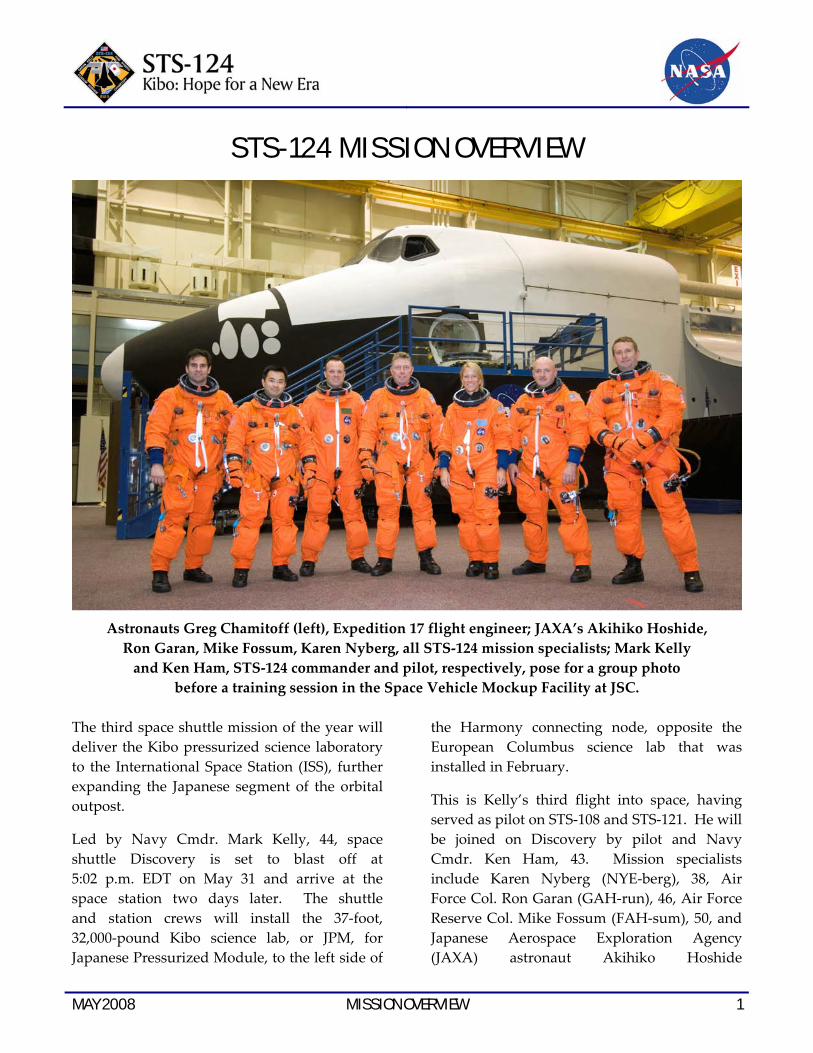
Astronauts Greg Chamitoff (left), Expedition 17 flight engineer; JAXA’s Akihiko Hoshide, Ron Garan, Mike Fossum, Karen Nyberg, all STS‐124 mission specialists; Mark Kelly and Ken Ham, STS‐124 commander and pilot, respectively, pose for a group photo
before a training session in the Space Vehicle Mockup Facility at JSC. The third space shuttle mission of the year will deliver the Kibo pressurized science laboratory to the International Space Station (ISS), further expanding the Japanese segment of the orbital outpost.
Led by Navy Cmdr. Mark Kelly, 44, space shuttle Discovery is set to blast off at 5:02 p.m. EDT on May 31 and arrive at the space station two days later. The shuttle and station crews will install the 37‐foot, 32,000‐pound Kibo science lab, or JPM, for Japanese Pressurized Module, to the left side of
the Harmony connecting node, opposite the European Columbus science lab that was installed in February.
This is Kelly’s third flight into space, having served as pilot on STS‐108 and STS‐121. He will be joined on Discovery by pilot and Navy Cmdr. Ken Ham, 43. Mission specialists include Karen Nyberg (NYE‐berg), 38, Air Force Col. Ron Garan (GAH‐run), 46, Air Force Reserve Col. Mike Fossum (FAH‐sum), 50, and Japanese Aerospace Exploration Agency (JAXA) astronaut Akihiko Hoshide
2 MISSION OVERVIEW MAY 2008
(Ah‐kee‐HEE‐koh Hoh‐SHEE‐day), 39. Fossum flew as a mission specialist with Kelly on STS‐121, and joins Kelly as the only crew members with previous spaceflight experience.
Greg Chamitoff (SHAM‐eh‐tawf), 45, will replace Garrett Reisman (REEZ‐muhn), 40, who arrived on the station in March and is completing three months as a station flight engineer. Reisman will return to Earth aboard Discovery.
A few hours after Discovery’s docking on the third day of the flight, Chamitoff and Reisman will exchange custom‐made Russian Soyuz
spacecraft seatliners. With that exchange, Chamitoff will become a part of the Expedition 17 space station crew and Reisman will become part of Discovery’s crew. Chamitoff will join expedition commander and Russian Air Force Lt. Col. Sergei Volkov (SIR‐gay VOLE‐koff), 35, and Flight Engineer Oleg Kononenko (AH‐leg Ko‐no‐NEHN‐ko), 43, who were launched to the complex in the Soyuz TMA‐12 spacecraft on April 8 from the Baikonur Cosmodrome in Kazakhstan.
Chamitoff will return to Earth in the fall on shuttle mission STS‐126, while Volkov and Kononenko will return in the Soyuz in October.
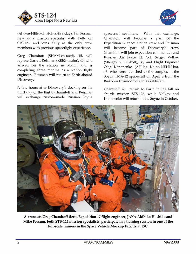
Astronauts Greg Chamitoff (left), Expedition 17 flight engineer; JAXA Akihiko Hoshide and Mike Fossum, both STS‐124 mission specialists, participate in a training session in one of the
full‐scale trainers in the Space Vehicle Mockup Facility at JSC.

MAY 2008 MISSION OVERVIEW 3
This graphic depicts the location of the STS‐124 payload hardware.
Kibo is 14 feet longer than Columbus and 9 feet longer than the U.S. Destiny laboratory. It joins the first component of the Japanese segment of the station, the Experiment Logistics Module‐Pressurized Section (ELM‐PS), that was launched on the last shuttle flight, STS‐123, in March. The logistics module will be robotically detached from the top port of Harmony during the mission and reattached to the top port of Kibo to serve as a storage depot.
The ELM‐PS was launched with eight racks of science gear and control equipment that will be transferred to the JPM for installation. In all, Kibo can house up to 23 racks of equipment and experiments that will involve research in space medicine, biology, Earth observations,
materials production, biotechnology and communications.
The new pressurized module also is equipped with its own robotic manipulator system and an airlock. The Japanese robotic device will be comprised of two separate six‐jointed arms, the main arm that measures 32.5 feet and can handle up to seven tons of hardware, and a small fine arm, a 6.2 foot extension that will be used for delicate payload operations. The small fine arm will be launched later on a new Japanese resupply ship for the station called the H‐II Transfer Vehicle (HTV).
The airlock ultimately will be used once the final components for the Japanese segment of

4 MISSION OVERVIEW MAY 2008
the station are delivered on shuttle mission STS‐127. That flight will install the Exposed Facility (EF) and the Exposed Logistics Module – Exposed Section (ELM‐ES). Some experiments will be mounted on a sliding platform that will move out of the depressurized airlock and handed off to the small fine arm for installation onto the exposed section. The airlock is not designed for spacewalks.
Nyberg will become the first astronaut to operate three robotic arms in orbit, as she uses the shuttle robotic arm for inspection of Discovery’s thermal protection system, the
station’s Canadarm2 to help unberth and install Kibo to Harmony, and the initial testing and checkout of the Japanese arm.
The inspection of Discovery’s thermal protection heat shield will be conducted differently than on previous flights. Due to the size of the giant Kibo module, the Orbiter Boom Sensor System (OBSS) extension that uses laser devices and cameras to inspect the shuttle’s wings and nose cap could not be mounted on Discovery’s starboard payload bay sill for launch. Instead, it was temporarily attached to the starboard truss on the station during STS‐123.
Astronaut Ken Ham, STS‐124 pilot, uses the virtual reality lab at JSC to train for some of his duties aboard the space shuttle and space station. This type of computer interface, paired with virtual reality training hardware and software, helps to prepare the entire
team for dealing with space station elements.
MAY 2008 MISSION OVERVIEW 5
As a result, on the second day of the flight normally reserved for OBSS inspection, the end effector camera on the shuttle’s robotic arm will be employed to capture initial imagery of Discovery’s heat‐resistant tiles. The boom will be retrieved on the fourth day, during the first of three planned spacewalks by Fossum and Garan, and handed back to the shuttle’s robotic arm. It will be used for a detailed inspection of the heat shield, if required, and later, a final inspection of Discovery after the shuttle has undocked from the station. The OBSS will then be brought back to Earth to be reflown on subsequent shuttle missions.
Kelly will be at Discovery’s aft flight deck controls as the shuttle approaches the station
for docking on the third day of the mission. Flying just 600 feet below the complex, Kelly will execute a slow back flip maneuver, presenting the belly of Discovery and other areas of its heat protective tiles to station residents Volkov and Reisman, who will use digital cameras equipped with 400 and 800 mm lenses to acquire detailed imagery of Discovery’s heat shield.
About two hours after Discovery links up to the forward docking port at the end of the Harmony module, hatches will be opened between the two spacecraft to allow the 10 crew members to greet one another for the start of nine days of joint operations.
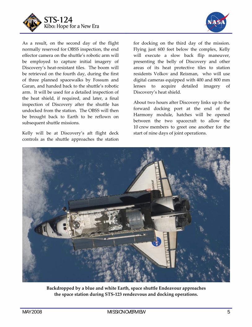
Backdropped by a blue and white Earth, space shuttle Endeavour approaches
the space station during STS‐123 rendezvous and docking operations.

6 MISSION OVERVIEW MAY 2008
Following a standard safety briefing by station commander Volkov, the crews will get to work, activating the Station to Shuttle Power Transfer System (SSPTS) to provide additional electricity for the longer operation of shuttle systems, exchanging Chamitoff for Reisman as the new station crew member, and preparing for the next day’s spacewalk.
Fossum and Garan will review procedures for the first spacewalk before moving into the Quest airlock for the so‐called overnight campout. The campout helps to purge nitrogen from their bloodstreams to prevent decompression sickness once they move out
into the vacuum of space clad in their spacesuits. Fossum, who conducted three spacewalks on STS‐121, will be designated EV 1, or extravehicular crew member 1. He will wear the suit bearing the red stripes for all three spacewalks, on flight days 4, 6, and 9. Garan will be performing his first spacewalks as extravehicular crew member 2 and will wear the suit with no stripes. Fossum and Garan will repeat the campout preparations the nights before the second and third spacewalks.
Kelly will help suit up Fossum and Garan for the spacewalks, and Ham will serve as the spacewalk choreographer.
JAXA astronaut Akihiko Hoshide and NASA astronaut Karen Nyberg, both STS‐124 mission specialists, participate in a training session in the simulation control area in the Neutral
Buoyancy Laboratory (NBL) at the Sonny Carter Training Facility near JSC.
MAY 2008 MISSION OVERVIEW 7
On the fourth day of the flight, Fossum and Garan will begin the first spacewalk by removing two Velcro straps used to restrain the elbow camera on the shuttle’s robotic arm. The straps ensure the camera will not contact the Kibo module during the arm’s unberthing from Discovery’s payload bay. At the same time, Hoshide and Chamitoff will operate the station’s robotic arm to grapple and remove the OBSS from its starboard truss stanchion and will hand it off to the shuttle’s arm, operated by Nyberg.
Fossum and Garan will then prepare the Kibo module for unberthing, disconnecting an electrical umbilical, and removing insulation and a cover on the module’s common berthing mechanism.
Nyberg will move from Discovery’s aft flight deck to the station’s robotic workstation and join Hoshide for the unberthing and installation of Kibo to the left side of Harmony. While Kibo is being installed, Fossum and Garan will work at the starboard Solar Alpha Rotary Joint (SARJ), which sustained unexplained damage to its outer race ring last year. Fossum and Garan will examine various areas of the joint, install a new Trundle Bearing Assembly to replace one that was removed during a station Expedition spacewalk last year, and test techniques for cleaning the damaged race ring.
On flight day 5, the shuttle crew will verify the condition of the delicate OBSS sensors to ensure that nothing was damaged during their exposure to the space environment over the past few months. To prepare for the activation of Kibo’s systems, Nyberg and Hoshide will set up equipment in the vestibule between Kibo and Harmony, including power cables that will route electricity to the new laboratory.
One of the first critical tasks will be the activation of Channel ʺBʺ power, the first of two power channels in Kibo to receive electricity from Harmony. That will provide the initial environmental conditions necessary for the crew to enter Kibo. With Channel “B” activated, command capability for Kibo will move from the Johnson Space Center (JSC) to the Tsukuba Space Center and JAXA’s Space Station Integration and Promotion Facility. The second channel, power channel “A”, will be activated by ground controllers in Tsukuba the following day.
Near the end of flight day 5, Kibo’s hatch will be opened. Hoshide will lead other crew members inside, wearing protective masks and goggles until the air in the new laboratory has been completely cleansed by equipment on the station.
The eight racks delivered to the Japanese Logistics Module on STS‐123 will be transferred to the JPM, starting with the control panel rack for the Japanese robotic arm. Two of the racks, called SAIBO (SIGH‐boe) and RYUTAI (Ree‐YOO‐tie), house biological and fluids experiments. Kibo’s systems will be fully checked out during the Expedition 17 increment, with completion of the lab commissioning expected by the end of August.
As the outfitting of the new laboratory begins, one of the adsorbent beds in the Destiny Laboratory’s Carbon Dioxide Removal Assembly (CDRA) will be replaced by Reisman and Chamitoff on flight day five. Over the past few months, the system has experienced uncommanded shutdowns that have been traced to bad sensors.

8 MISSION OVERVIEW MAY 2008
Once all of Kibo’s new racks are transferred, power and utility connections will be made on flight day 6 while Fossum and Garan conduct the second of their three spacewalks.
During the second excursion, the two spacewalkers will install television cameras on the outside of Kibo, remove thermal covers and insulation from the Kibo robotic arm, prepare the upper berthing port on Kibo for the relocation of the logistics module, retrieve a failing camera system from the left truss and prepare for the replacement of an expended nitrogen tank assembly on the starboard truss. The faulty camera system will be repaired and reinstalled on the left truss during the mission’s third spacewalk.
On flight day 7, if necessary, Ham, Fossum and Garan will use the shuttle’s robotic arm and its attached boom sensor extension to perform a detailed, focused inspection of Discovery’s wing leading edges and nose cap, to quantify any heat shield damage.
While that takes place, Hoshide and Reisman will remove electrical jumper cables from the vestibule between Kibo and Harmony, and depressurize the passageway in preparation for relocating the logistics module.
With Nyberg and Chamitoff at the controls, the station’s Canadarm2 will unberth the recently installed logistics module from the top berthing port on Harmony and maneuver it for installation at its permanent home atop Kibo. Logistics module and vestibule leak checks and pressurization will follow, leading to the final activity of the day, the activation of the new Japanese robotic arm.
The next day, flight day 8, Hoshide and Nyberg will test the new Japanese arm’s systems, most notably the arm’s hold and release mechanism. That will set the stage for its initial deployment. Hoshide and Nyberg also will install additional equipment in the new passageway between the JLM and the laboratory. Fossum and Garan will prepare for the third and final spacewalk of the mission.
On flight day 9, the pair will exit the Quest airlock one last time to conduct what they have termed a windshield wiper maneuver, removing a spare nitrogen tank assembly from a spare parts platform on the station’s left truss and exchanging it with a depleted tank on the starboard truss. Garan will have ample time to enjoy the view as he is maneuvered back and forth at the end of the station robotic arm, hauling the tanks to their respective locations.
Fossum and Garan will work during the final segment of the spacewalk to remove thermal insulation on the Japanese robotic arm and launch locks, as well as locks on the two windows on the aft cone of the Japanese lab. Once the spacewalk has been completed, the new robotic arm will be deployed to its fully extended position and maneuvered to its stowed position. Its full checkout will be completed by September.
On flight day 10, the crews will work to change out components in the Quest airlock used to charge the batteries that provide the U.S. spacesuits with internal power during spacewalks. The toxicity levels of the current battery charger modules have slightly increased due to their age, and with an extra docked day available, managers elected to install new charging units. The crew also will conduct a

MAY 2008 MISSION OVERVIEW 9
thorough checkout of the brakes on the newly activated Japanese robotic arm on Kibo.
The crew will have off duty time on flight day 11, relaxing for a portion of the day before transferring spacewalk equipment and at least one spacesuit back to Discovery. At the end of the day, the two crews will bid farewell to one another and close hatches between Discovery and the station, leaving Chamitoff on the station while Reisman begins final preparations for his return to Earth.
On flight day 12, Discovery will undock from the station. Ham, flying the shuttle from the aft flight deck, will guide the orbiter on a fly around of the complex so the crew can capture detailed imagery of the newly installed Kibo and the station’s new configuration. Once Discovery’s maneuvering jets are fired to enable it to separate from the station, Ham, Nyberg, Garan and Fossum will take turns with the shuttle’s robotic arm and the OBSS to conduct a late inspection of the shuttle’s heat shield, a final opportunity to confirm Discovery’s readiness to return to Earth.
Backdropped by Earth’s horizon and the blackness of space, the space station is seen from space shuttle Endeavour as the two spacecraft begin their separation.

10 MISSION PERSONNEL MAY 2008
The crew will enjoy an off duty day on flight day 13 before berthing the boom sensor system extension onto the starboard sill of the payload bay and shutting down the shuttle’s robotic arm systems.
On flight day 14, Kelly, Ham and Garan will settle into their seats on the flight deck to conduct the traditional checkout of the orbiter’s flight control surfaces and steering jets in preparation for landing the next day. The crew
will stow its gear and Reisman will set up a special recumbent seat in the middeck to assist him as he readapts to Earth’s gravity following three months of weightlessness.
Discovery is scheduled to return to Earth on Saturday, June 14, landing at the Kennedy Space Center just after noon, Eastern Time, bringing to an end its 35th mission, the 26th shuttle flight to the space station and the 123rd flight in shuttle program history.
While seated at the commander’s station, astronaut Mark Kelly, STS‐124 commander,
participates in a training session in the crew compartment trainer in the Space Vehicle Mockup Facility at JSC.

MAY 2008 TIMELINE OVERVIEW 11
TIMELINE OVERVIEW Flight Day 1
• Launch
• Payload Bay Door Opening
• Ku‐Band Antenna Deployment
• Shuttle Robotic Arm Activation
• Umbilical Well and Handheld External Tank Video and Stills Downlink
Flight Day 2
• Discovery Thermal Protection System Survey with Shuttle Robotic Arm End Effector Camera (limited inspection)
• Extravehicular Mobility Unit Checkout
• Centerline Camera Installation
• Orbiter Docking System Ring Extension
• Orbital Maneuvering System Pod Survey
• Rendezvous Tools Checkout
Flight Day 3
• Rendezvous with the Space Station
• Rendezvous Pitch Maneuver Photography by the Expedition 17 Crew
• Docking to Harmony/Pressurized Mating Adapter‐2
• Hatch Opening and Welcoming
• Chamitoff and Reisman exchange Soyuz seatliners; Chamitoff joins Expedition 17, Reisman joins the STS‐124 crew
• Extravehicular Activity (EVA) 1 Procedure Review
• EVA 1 Campout by Fossum and Garan
Flight Day 4
• Canadarm2 Grapple of Orbiter Boom Sensor System (OBSS) on S1 Truss
• EVA 1 by Fossum and Garan [OBSS Transfer to Shuttle Robotic Arm; Japanese Pressurized Module (JPM) preparations for unberth; Shuttle Robotic Arm Elbow Camera Strap Removal; Starboard Solar Alpha Rotary Joint (SARJ) Datum A surface inspection, Trundle Bearing Assembly No. 5 reinstallation and outer race ring cleaning Detailed Test Objective (DTO)]
• Canadarm2 grapple and unberth of JPM
• Installation of JPM on port side of Harmony
Flight Day 5
• OBSS Sensor Checkout
• Carbon Dioxide Removal Assembly Bed No. 2 Removal and Replacement
• JPM Channel B Activation
• JPM Vestibule Preparation
• JPM Hatch Opening and Ingress
• EVA 2 Procedure Review
• Japanese Module Robotic Arm Control Panel Rack Transfer from Logistics Module to Pressurized Module
• EVA 2 Campout by Fossum and Garan

12 TIMELINE OVERVIEW MAY 2008
Flight Day 6
• EVA 2 by Fossum and Garan (Japanese Module TV Equipment Setup; Japanese Robotic Arm Thermal Cover Removal; Harmony Zenith Berthing Port Preparations; Nitrogen Tank Assembly replacement preparations)
• Japanese Module Rack Transfer from Logistics Module to Pressurized Module
• Japanese Module Robotic Arm Console Setup
• JPM Channel A Activation
• JPM Egress
• Harmony Zenith Berthing Port Control Panel Assembly Installation
Flight Day 7
• OBSS Focused Inspection of Discovery’s Thermal Protection System (if required)
• Japanese Logistics Module (JLM) Vestibule Outfitting and Depressurization
• Canadarm2 Grapple and Unberth of JLM from Zenith Berthing Port of Harmony
• JLM Installation to Zenith Berthing Port of JPM
• Japanese Robotic Arm Activation
• JPM/Logistics Module Vestibule Leak Checks
Flight Day 8
• Japanese Robotic Arm Initial Deployment and Checkout
• Japan Aerospace Exploration Agency (JAXA) VIP Event
• JLM Vestibule Outfitting
• Port TV Camera Repairs
• EVA 3 Procedure Review
• EVA 3 Campout by Fossum and Garan
Flight Day 9
• EVA 3 by Fossum and Garan (Nitrogen Tank Assembly Replacement on S1 Truss; Camera Port 9 TV Equipment Installation; Japanese Robotic Arm Thermal Cover Removal)
• Japanese Robotic Arm Final Deployment and Stowage
Flight Day 10
• Battery Charger Module Changeout in Quest Airlock
• Japanese Robotic Arm Brake Checkout
• Joint Crew News Conference
Flight Day 11
• Crew Off Duty Time
• Final Farewells and Hatch Closure
• Rendezvous Tools Checkout

MAY 2008 TIMELINE OVERVIEW 13
Flight Day 12
• Undocking
• Fly‐around of the ISS
• Final Separation
• OBSS Late Inspection of Discovery’s Thermal Protection System
Flight Day 13
• Crew Off Duty Time
• OBSS Stowage
Flight Day 14
• Flight Control System Checkout
• Reaction Control System Hot‐Fire Test
• Cabin Stowage
• Reisman’s Recumbent Seat Set Up
• Crew Deorbit Briefing
• Ku‐Band Antenna Stowage
Flight Day 15
• Deorbit Preparations
• Payload Bay Door Closing
• Deorbit Burn
• KSC Landing

14 TIMELINE OVERVIEW MAY 2008
This page intentionally left blank.
MAY 2008 MISSION PROFILE 15
MISSION PROFILE CREW
Commander: Mark Kelly Pilot: Ken Ham Mission Specialist 1: Karen Nyberg Mission Specialist 2: Ron Garan Mission Specialist 3: Mike Fossum Mission Specialist 4: Akihiko Hoshide Mission Specialist 5: Greg Chamitoff (Up) Mission Specialist 5: Garrett Reisman (Down)
LAUNCH
Orbiter: Discovery (OV‐103) Launch Site: Kennedy Space Center
Launch Pad 39A Launch Date: May 31, 2008 Launch Time: 5:02 p.m. EDT (Preferred
In‐Plane launch time for 5/31)
Launch Window: 5 Minutes Altitude: 122 Nautical Miles
(140 Miles) Orbital Insertion; 185 NM (213 Miles) Rendezvous
Inclination: 51.6 Degrees Duration: 13 Days 17 Hours
43 Minutes
VEHICLE DATA
Shuttle Liftoff Weight: 4,525,084 pounds
Orbiter/Payload Liftoff Weight: 269,123 pounds
Orbiter/Payload Landing Weight: 203,320 pounds
Software Version: OI‐32
Space Shuttle Main Engines:
SSME 1: 2047 SSME 2: 2044 SSME 3: 2054 External Tank: ET‐126 SRB Set: BI‐133 RSRM Set: 102
SHUTTLE ABORTS
Abort Landing Sites
RTLS: Kennedy Space Center Shuttle Landing Facility
TAL: Primary – Zaragoza, Spain Alternates – Moron, Spain and Istres, France
AOA: Primary – Kennedy Space Center Shuttle Landing Facility; Alternate – White Sands Space Harbor
LANDING
Landing Date: June 14, 2008 Landing Time: 10:45 a.m. EDT Primary landing Site: Kennedy Space Center
Shuttle Landing Facility
PAYLOADS
Kibo Pressurized Module, Japanese Remote Manipulator System

16 MISSION PROFILE MAY 2008
This page intentionally left blank.

MAY 2008 MISSION PRIORITIES 17
MISSION PRIORITIES 1. Retrieve Orbiter Boom Sensor System
(OBSS) from S1 truss
2. Release shuttle arm’s elbow camera launch locks
3. Rotate Expedition 16/17 International Space Station (ISS) Flight Engineer and NASA Science Officer Garrett Reisman with Expedition 17 Flight Engineer and NASA Science Officer Greg Chamitoff
4. Install Japan Aerospace Exploration Agency’s Japanese Experiment Module (JEM) – Pressurized Module (JPM) onto Harmony port using the station’s robotic arm
5. Activate a single power channel for JPM systems
6. Outfit JPM for operations and install JEM Remote Manipulator System (RMS) rack to verify JEM RMS temperatures
7. Activate second JPM power/avionics channel
8. Perform JEM RMS preparations and initial deploy
9. Prepare JPM zenith Active Common Berthing Mechanism (ACBM) for Japanese Experiment Logistics Module – Pressurized Section (ELM‐PS) relocation
10. Remove and replace the Starboard 1 Nitrogen Tank Assembly (NTA) using spare NTA located on External Stowage Platform 3
11. Perform Carbon Dioxide Removal Assembly bed removal and replacement
12. Remove Camera Port 9 External Television Camera Group (ETVCG) and remove and replace Television Camera Interface Controller
13. Reinspect starboard Solar Alpha Rotary Joing (SARJ) surface
14. Transfer remaining racks from ELM‐PS to JPM
15. Relocate ELM‐PS to JPM zenith ACBM
16. Perform starboard SARJ outer ring cleaning Detailed Test Objective
17. Perform Node 1 to airlock Common Cabin Air Assembly check valve hose installation
18. Perform Battery Charger Module removal and replacement
19. Perform ELM‐PS/JPM vestibule outfitting and complete ELM‐PS activation
20. Perform remaining spacewalk tasks:
(a) Release two JPM ACBM Micrometeoroid Orbital Debris (MMOD) shield restraints
(b) Install JPM trunnion and keel pin covers
(c) Release JPM window shutter launch locks
(d) Install Theromostat Box Assembly 5 on starboard SARJ
(e) Deploy JPM MMOD shields
(f) Install two EVA gap spanners
21. Perform final JEM RMS deploy and brake checkout
22. Transfer required nitrogen

18 MISSION PRIORITIES MAY 2008
This page intentionally left blank.

MAY 2008 MISSION PERSONNEL 19
MISSION PERSONNEL KEY CONSOLE POSITIONS FOR STS-124
Flt. Director CAPCOM PAO
Ascent Norm Knight Terry Virts Kevin Ford (Weather)
Rob Navias
Orbit 1 (Lead) Matt Abbott Nick Patrick Rob Navias (Lead)
Orbit 2 Mike Sarafin Al Drew Brandi Dean
Planning Paul Dye/ Tony Ceccacci
Shannon Lucid Josh Byerly
Entry Richard Jones Terry Virts Kevin Ford (Weather)
Rob Navias
Shuttle Team 4 Rick LaBrode N/A N/A
ISS Orbit 1 Bob Dempsey Mark Vande Hei N/A
ISS Orbit 2 (Lead) Annette Hasbrook Chris Cassidy N/A
ISS Orbit 3 Emily Nelson Mike Jensen N/A
Station Team 4 Brian Smith N/A N/A
International Partner FD – Holly Ridings (interfaces with Japan Aerospace Exploration Agency)
HQ PAO Representative at KSC for Launch – John Yembrick
JSC PAO Representative at KSC for Launch – John Ira Petty
KSC Launch Commentator – Allard Beutel
KSC Launch Director – Mike Leinbach
NASA Launch Test Director – Jeff Spaulding

20 MISSION PERSONNEL MAY 2008
This page intentionally left blank.
STS-124 DISCOVERY CREW
MAY 2008 CREW 21
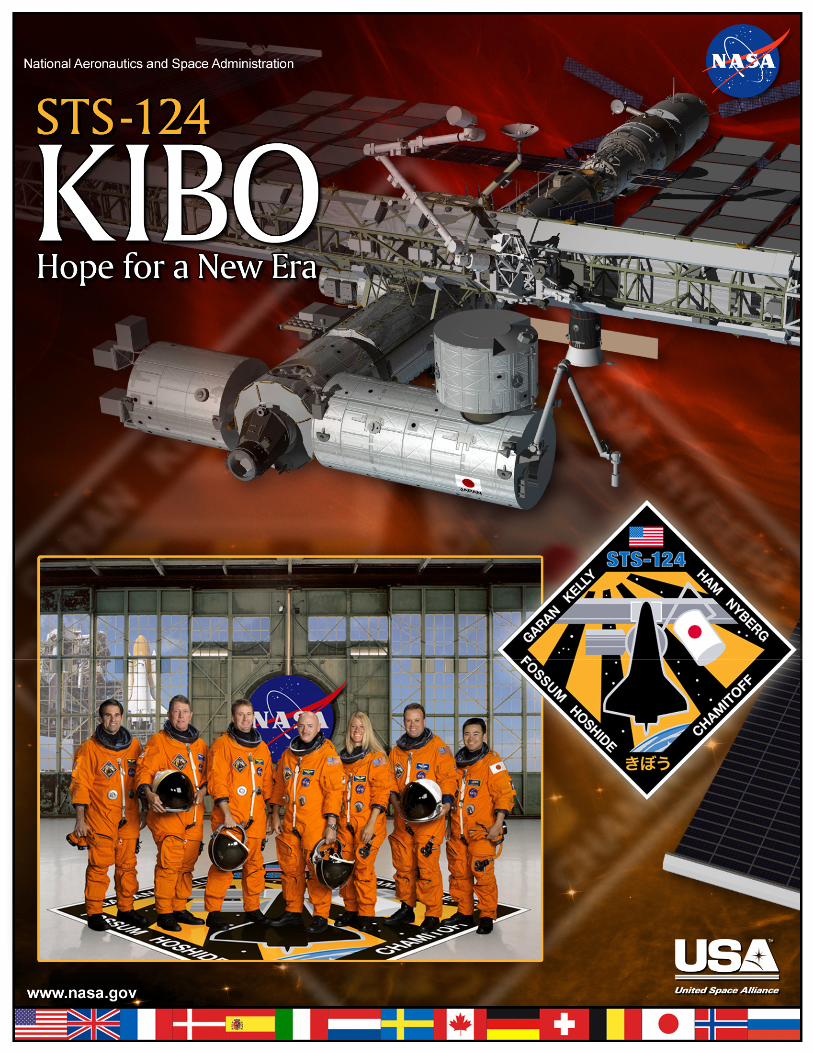
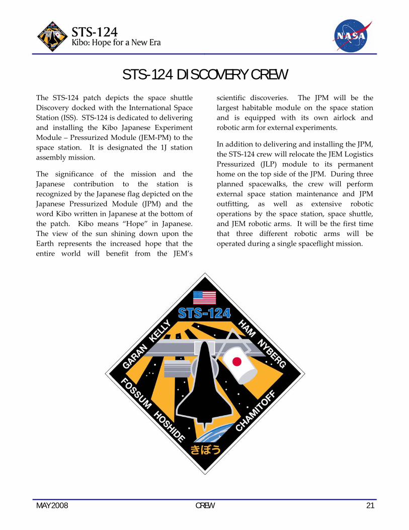
The STS‐124 patch depicts the space shuttle Discovery docked with the International Space Station (ISS). STS‐124 is dedicated to delivering and installing the Kibo Japanese Experiment Module – Pressurized Module (JEM‐PM) to the space station. It is designated the 1J station assembly mission.
The significance of the mission and the Japanese contribution to the station is recognized by the Japanese flag depicted on the Japanese Pressurized Module (JPM) and the word Kibo written in Japanese at the bottom of the patch. Kibo means “Hope” in Japanese. The view of the sun shining down upon the Earth represents the increased hope that the entire world will benefit from the JEM’s
scientific discoveries. The JPM will be the largest habitable module on the space station and is equipped with its own airlock and robotic arm for external experiments.
In addition to delivering and installing the JPM, the STS‐124 crew will relocate the JEM Logistics Pressurized (JLP) module to its permanent home on the top side of the JPM. During three planned spacewalks, the crew will perform external space station maintenance and JPM outfitting, as well as extensive robotic operations by the space station, space shuttle, and JEM robotic arms. It will be the first time that three different robotic arms will be operated during a single spaceflight mission.

22 CREW MAY 2008
These seven astronauts take a break from training to pose for the STS‐124 crew portrait. From the left are astronauts Greg Chamitoff, Mike Fossum, both mission specialists; Ken Ham, pilot; Mark Kelly, commander; Karen Nyberg, Ron Garan and JAXA’s Akihiko Hoshide, all mission specialists.
The crew members are wearing training versions of their shuttle launch and entry suits. Short biographical sketches of the crew follow with detailed background available at:
http://www.jsc.nasa.gov/Bios/
MAY 2008 CREW 23
STS-124 CREW BIOGRAPHIES
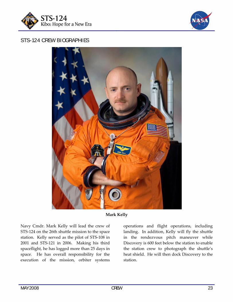
Mark Kelly
Navy Cmdr. Mark Kelly will lead the crew of STS‐124 on the 26th shuttle mission to the space station. Kelly served as the pilot of STS‐108 in 2001 and STS‐121 in 2006. Making his third spaceflight, he has logged more than 25 days in space. He has overall responsibility for the execution of the mission, orbiter systems
operations and flight operations, including landing. In addition, Kelly will fly the shuttle in the rendezvous pitch maneuver while Discovery is 600 feet below the station to enable the station crew to photograph the shuttle’s heat shield. He will then dock Discovery to the station.
24 CREW MAY 2008
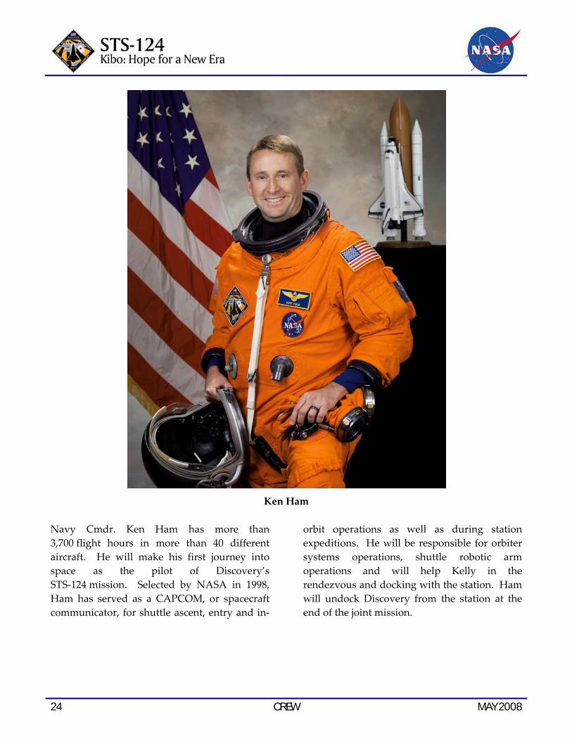
Ken Ham
Navy Cmdr. Ken Ham has more than 3,700 flight hours in more than 40 different aircraft. He will make his first journey into space as the pilot of Discovery’s STS‐124 mission. Selected by NASA in 1998, Ham has served as a CAPCOM, or spacecraft communicator, for shuttle ascent, entry and in‐
orbit operations as well as during station expeditions. He will be responsible for orbiter systems operations, shuttle robotic arm operations and will help Kelly in the rendezvous and docking with the station. Ham will undock Discovery from the station at the end of the joint mission.

MAY 2008 CREW 25
Karen Nyberg
Astronaut Karen Nyberg will be making her first spaceflight as mission specialist 1. She holds a doctorate in mechanical engineering. Selected as an astronaut in 2000, Nyberg has worked in the astronaut office’s space station operations branch and served as a crew support astronaut for Expedition 6. She served as an aquanaut in the Aquarius undersea research
habitat for seven days as part of the 10th NASA Extreme Environment Mission Operations (NEEMO) in 2006. During STS‐124 she will operate the shuttle and station robotic arms for Discovery’s heat shield inspections and Kibo assembly operations. She also will work with the new Japanese robotic arm.

26 CREW MAY 2008
Ron Garan
Air Force Col. Ron Garan will be making his first flight into space as mission specialist 2. Selected as an astronaut in 2000, Garan has worked in the astronaut office space station and space shuttle operations branches. He served
as an aquanaut for 18 days for the ninth NEEMO mission in 2006. Garan will conduct three spacewalks and operate the shuttle robotic arm during STS‐124.
MAY 2008 CREW 27
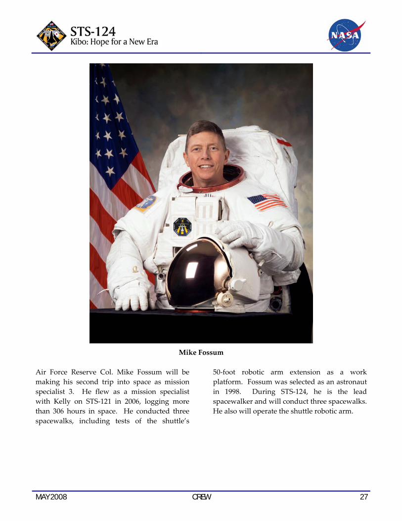
Mike Fossum
Air Force Reserve Col. Mike Fossum will be making his second trip into space as mission specialist 3. He flew as a mission specialist with Kelly on STS‐121 in 2006, logging more than 306 hours in space. He conducted three spacewalks, including tests of the shuttle’s
50‐foot robotic arm extension as a work platform. Fossum was selected as an astronaut in 1998. During STS‐124, he is the lead spacewalker and will conduct three spacewalks. He also will operate the shuttle robotic arm.
28 CREW MAY 2008
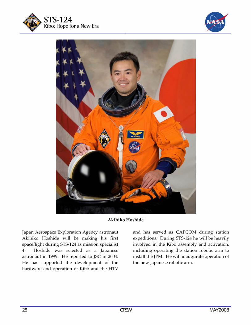
Akihiko Hoshide
Japan Aerospace Exploration Agency astronaut Akihiko Hoshide will be making his first spaceflight during STS‐124 as mission specialist 4. Hoshide was selected as a Japanese astronaut in 1999. He reported to JSC in 2004. He has supported the development of the hardware and operation of Kibo and the HTV
and has served as CAPCOM during station expeditions. During STS‐124 he will be heavily involved in the Kibo assembly and activation, including operating the station robotic arm to install the JPM. He will inaugurate operation of the new Japanese robotic arm.

MAY 2008 CREW 29
Greg Chamitoff
Astronaut Greg Chamitoff will be making his first spaceflight on his way to the International Space Station. He holds a doctorate in aeronautics and astronautics. Selected by NASA in 1998, Chamitoff has worked in the astronaut office robotics branch, was the lead CAPCOM for Expedition 9 and was a crew support astronaut for Expedition 6. Chamitoff
served as an aquanaut for nine days as part of the third NEEMO mission in 2002. During STS‐124 he will operate the station robotic arm. He will serve as a flight engineer and science officer during Expedition 17 aboard station. He is scheduled to return to Earth on shuttle mission STS‐126, targeted for launch in October.

30 CREW MAY 2008
Garrett Reisman
Astronaut Garrett Reisman will be returning to Earth from the International Space Station on STS‐124. He holds a doctorate in mechanical engineering. Selected by NASA in 1998, Reisman has worked in the astronaut office robotics and advanced vehicles branches. He was part of the fifth NEEMO mission, living on the bottom of the sea in the Aquarius habitat for
two weeks in 2003. He arrived at the station on STS‐123 and conducted one spacewalk, assisted with spacewalk intravehicular duties and operated the station robotic arm during the flight. He served as a flight engineer and science officer during the final weeks of Expedition 16 and the beginning of Expedition 17 aboard the station.

MAY 2008 PAYLOAD OVERVIEW 31
PAYLOAD OVERVIEW KIBO’S MAIN EXPERIMENT MODULE AND ROBOTIC ARM FLY TO THE STATION
On this second of the three Kibo assembly missions, the Japanese Pressurized Module (JPM), and Japanese Experiment Module (JEM) Remote Manipulator System (JEMRMS) will fly to the space station.
The JPM is the main experiment module that accommodates core systems that are
indispensable for Kibo operations. Most crew activities related to Kibo, such as experiments, robotic operations, voice communications with the ground, and other routine activities, are mainly performed in/from the JPM.
The JEMRMS is a robotic arm intended for supporting experiment and maintenance activities on the exposed areas of Kibo. The crew will manipulate the JEMRMS from a robotic control workstation, called the “JEMRMS Console,” installed in the JPM.
Illustration of the Kibo final configuration
32 PAYLOAD OVERVIEW MAY 2008
THE STS-124 MISSION WILL BRING KIBO INTO A FULLY OPERATIONAL STATE
On flight day 4, the Japanese Pressurized Module (JPM) will be attached to the port side of Harmony (Node 2).
Once the JPM is installed on the station, initial activation will be carried out by the crew. After the system racks are transferred from the Japanese Logistics Module (JLM) to the JPM, full activation of the JPM will be performed by the JAXA Flight Control Team (JFCT), at the Tsukuba Space Center (TKSC) in Japan. Following full activation, the JFCT will take responsibility for controlling Kibo operations realtime. Kibo systems data will be sent to TKSC, and commands from Tsukuba will be uplinked through the station data management system.
On flight day 7, the JLM, which was delivered to the space station on the STS‐123 mission, will
be relocated from the zenith side of Harmony (Node 2) to the zenith side of the JPM. At this point, the assembly of Kibo’s pressurized facilities will be complete.
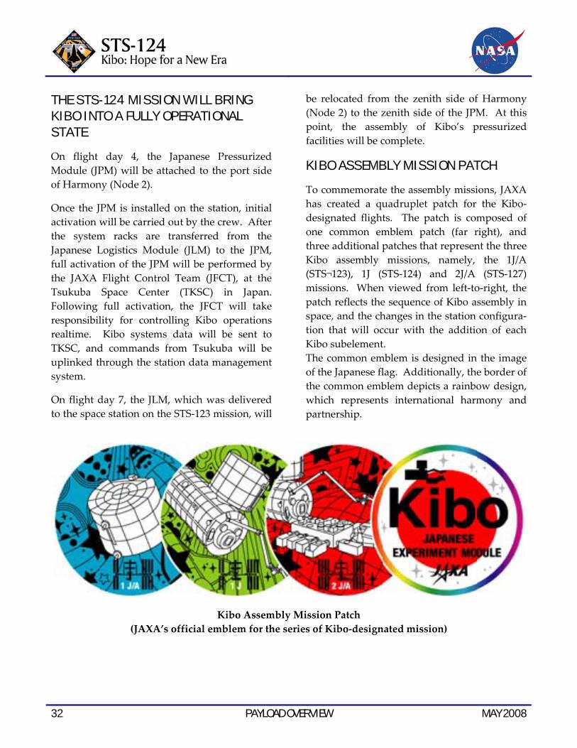
KIBO ASSEMBLY MISSION PATCH
To commemorate the assembly missions, JAXA has created a quadruplet patch for the Kibo‐ designated flights. The patch is composed of one common emblem patch (far right), and three additional patches that represent the three Kibo assembly missions, namely, the 1J/A (STS¬123), 1J (STS‐124) and 2J/A (STS‐127) missions. When viewed from left‐to‐right, the patch reflects the sequence of Kibo assembly in space, and the changes in the station configura‐tion that will occur with the addition of each Kibo subelement. The common emblem is designed in the image of the Japanese flag. Additionally, the border of the common emblem depicts a rainbow design, which represents international harmony and partnership.
Kibo Assembly Mission Patch (JAXA’s official emblem for the series of Kibo‐designated mission)
MAY 2008 PAYLOAD OVERVIEW 33
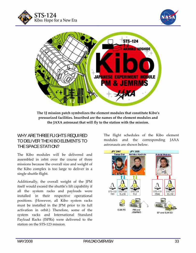
The 1J mission patch symbolizes the element modules that constitute Kibo’s pressurized facilities. Inscribed are the names of the element modules and
the JAXA astronaut that will fly to the station with the mission.
WHY ARE THREE FLIGHTS REQUIRED TO DELIVER THE KIBO ELEMENTS TO THE SPACE STATION?
The Kibo modules will be delivered and assembled in orbit over the course of three missions because the overall size and weight of the Kibo complex is too large to deliver in a single shuttle flight.
Additionally, the overall weight of the JPM itself would exceed the shuttle’s lift capability if all the system racks and payloads were installed in their respective operational positions. (However, all Kibo system racks must be installed in the JPM prior to its full activation in orbit.) Therefore, some of the system racks and International Standard Payload Racks (ISPRs) were delivered to the station on the STS‐123 mission.
The flight schedules of the Kibo element modules and the corresponding JAXA astronauts are shown below.

34 PAYLOAD OVERVIEW MAY 2008
KIBO-RELATED MISSIONS WILL CONTINUE
Assembly of the Kibo pressurized facilities will be completed during the STS‐124 mission. In turn, the Kibo Exposed Facility (EF) and the Experiment Logistics Module—Exposed Section (ELM‐ES) are scheduled to be launched on the STS‐127 (2J/A) mission.
By the summer of 2009, Japan’s unmanned cargo transfer spacecraft, the HTV, will initiate its operations. The HTV will be launched aboard the H‐IIB launch vehicle from the Tanegashima Space Center in Japan, and begin transferring supplies, payloads and cargo, both pressurized and unpressurized, to the station.
JAPANESE PRESSURIZED MODULE (JPM) OVERVIEW
The JPM will be attached to the Common Berthing Mechanism (CBM) on the port side of Harmony (Node 2) on flight day 4.
The JPM will be the largest pressurized module on the station. The module is cylindrical in shape and is 11.2 meters (36.7 feet) long and 4.4 meters (14.4 feet) in diameter, about the size of a large tour bus. The JPM has a total mass (when fully assembled) of 15.9 tons. Up to 23 racks (10 of which are international standard payload racks) can be accommodated inside the JPM.
External Structure of the JPM

MAY 2008 PAYLOAD OVERVIEW 35
The JPM is primarily equipped with station common hardware. Two grapple fixtures are mounted on the external surface to allow the space station’s robotic arm to grapple and move the JPM. An Active CBM is provided on the zenith side of the module for attaching the JLM.
The JPM has a small scientific airlock through which exposed experiments, or orbital replacement units (ORUs), can be transferred between the Kibo pressurized and unpressurized facilities. In addition, the JPM
has two windows and a unique berthing mechanism that connects the EF to the JPM. Kibo’s robotic arm is fixed at the upper side of the JPM endcone.
The JPM has an 8‐rack equivalent length, but the presence of the JEM airlock and the CBM hatch for access to the JLM limits rack installation. For each of the four walls inside the JPM, with the exception of the zenith wall, six racks can be installed in a continuous row. The zenith wall will hold five racks in a row.
COMPARISON OF JPM WITH OTHER SPACE STATION MODULES
JPM (JAXA)
Destiny (NASA)
Columbus (ESA)
JLM (JAXA)
Length 11.2m (36.7 ft) 8.5m (27.9 ft) 6.8m (22.3 ft) 4.2m (13.8 ft)
Launch Weight 14.8t 14.5t 12.7t 8.4t
Maximum number of racks installed (number of ISPRs)
23 (ISPR: 10) 24 (ISPR: 13) 16 (ISPR: 10) 8 (ISPR: 0)
Number of the racks carried at launch 4 5 + 8ZSR 8 + 2ZSR 8 *1)
*1) All eight racks that were delivered to the station inside the JLM (STS-123) will be transferred to the JPM during the STS-124 mission.

36 PAYLOAD OVERVIEW MAY 2008
Kibo configuration after the STS‐124 mission (1J Assembly flight)
Kibo configuration after the STS‐127 mission (2J/A Assembly flight)
MAY 2008 PAYLOAD OVERVIEW 37
KIBO-SPECIFIC STRUCTURES
Most of the interface hardware and tools on board Kibo are station common equipment (for example, common berthing mechanisms, hatches and various grapple fixtures). However, some of the hardware and tools are Kibo‐unique system designs. This section describes the Kibo‐specific equipment.
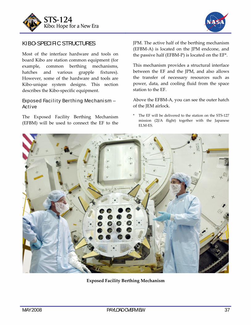
Exposed Facility Berthing Mechanism – Active
The Exposed Facility Berthing Mechanism (EFBM) will be used to connect the EF to the
JPM. The active half of the berthing mechanism (EFBM‐A) is located on the JPM endcone, and the passive half (EFBM‐P) is located on the EF*.
This mechanism provides a structural interface between the EF and the JPM, and also allows the transfer of necessary resources such as power, data, and cooling fluid from the space station to the EF.
Above the EFBM‐A, you can see the outer hatch of the JEM airlock.
* The EF will be delivered to the station on the STS‐127 mission (2J/A flight) together with the Japanese ELM‐ES.
Exposed Facility Berthing Mechanism
38 PAYLOAD OVERVIEW MAY 2008
JPM Windows
The JPM is equipped with two windows, located just above the JEM airlock. The crew can clearly see the Kibo unpressurized facilities through these windows.
The crew also will be able to observe and monitor the unpressurized facilities with external television cameras mounted on the JPM.
JPM Windows (Note that the window covers are closed)
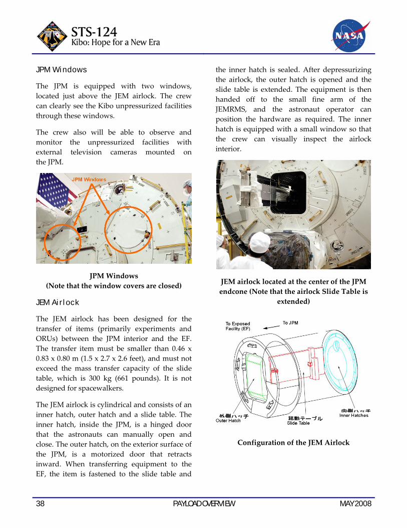
JEM Airlock
The JEM airlock has been designed for the transfer of items (primarily experiments and ORUs) between the JPM interior and the EF. The transfer item must be smaller than 0.46 x 0.83 x 0.80 m (1.5 x 2.7 x 2.6 feet), and must not exceed the mass transfer capacity of the slide table, which is 300 kg (661 pounds). It is not designed for spacewalkers.
The JEM airlock is cylindrical and consists of an inner hatch, outer hatch and a slide table. The inner hatch, inside the JPM, is a hinged door that the astronauts can manually open and close. The outer hatch, on the exterior surface of the JPM, is a motorized door that retracts inward. When transferring equipment to the EF, the item is fastened to the slide table and
the inner hatch is sealed. After depressurizing the airlock, the outer hatch is opened and the slide table is extended. The equipment is then handed off to the small fine arm of the JEMRMS, and the astronaut operator can position the hardware as required. The inner hatch is equipped with a small window so that the crew can visually inspect the airlock interior.
JEM airlock located at the center of the JPM endcone (Note that the airlock Slide Table is
extended)
Configuration of the JEM Airlock

MAY 2008 PAYLOAD OVERVIEW 39
JAXA astronaut Koichi Wakata reviewing procedures for removal of the JEM airlock
forward launch locks
JEM airlock as seen from the PM interior. Note that the inner hatch is equipped with a window, a pressure gauge and operating
handle.
STS‐124 crew members participating in a Kibo‐specific training session using the JPM trainer at the TKSC. The JLM hatch is located directly above the JEM airlock.
40 PAYLOAD OVERVIEW MAY 2008
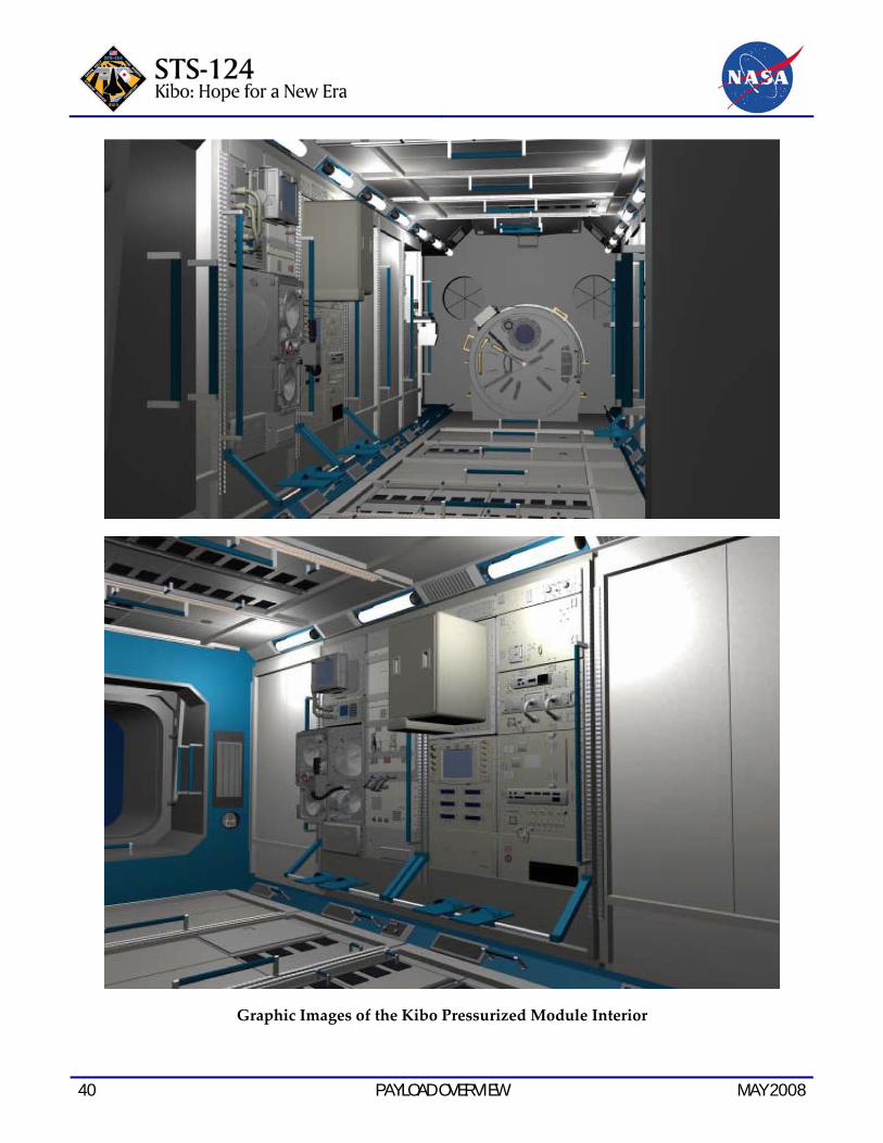
Graphic Images of the Kibo Pressurized Module Interior

MAY 2008 PAYLOAD OVERVIEW 41
JEMRMS
The Japanese Experiment Module Remote Manipulator System (JEMRMS) is a robotic arm system designed to support and manipulate experiments and perform maintenance tasks on the Kibo unpressurized facilities.
The JEMRMS is actually composed of two arms, a 10‐meter‐long (33‐foot‐long) main arm (MA) and a 2‐meter‐long (6‐foot‐long) small fine arm. (Note that the small fine arm will not be launched on STS‐124, it will be delivered to the station on a future mission.)
Both arms have six independent joints and provide great dexterity in movement, which is very similar to the human arm. The robotic control workstation, known as the JEMRMS Console, is used for manipulating the JEMRMS. Remote television cameras are mounted on both robotic arms, and they enable the crew to control the JEMRMS from inside the JPM.
Using these robotic arms, the space station crew can exchange exposed payloads and ORUs installed on the EF and ELM‐ES. The main arm will primarily be used to transfer large objects, and the small fine arm will handle the smaller, more delicate items.
The JEMRMS is designed to operate for more than 10 years in orbit. The JEMRMS also incorporates a modular design which allows many major components to be exchanged or replaced in case of failure. Some of the arm subcomponents can be repaired by intravehicular activity (IVA) operations, but repair of the main arm can only be performed by EVA.
Launch configuration of the JEMRMS
JEMRMS console rack (trainer)

42 PAYLOAD OVERVIEW MAY 2008
Items Specifications
Main Arm (MA) Small Fine Arm (SFA)
Structure type Main Arm with attached Small Fine Arm. Both arms have 6 joints.
Degrees of freedom 6 6 Length m 10 2.2 Mass (weight) kg 780 190
Handling Capacity kg Max. 7,000
Max. 80 with Compliance Control Mode Max. 300 without Compliance Control Mode
Positioning accuracy mm Translation 50(+/-) Translation 10(+/-) deg. Rotation 1(+/-) Rotation 1(+/-)
Translation/ rotation speed mm/s
60 (P/L: 600 to 3,000 kg) (1,323 to 6,614 pounds)
50 (P/L: less than 80 kg) (176 pounds)
30 (P/L: less than 3,000 kg) (6,614 pounds)
25 (P/L: 80 to 300 kg) (176 to 661 pounds)
20 (P/L: 3,000 to 7,000 kg) (6,614 to 15,432 pounds)
Maximum tip force N More than 30 More than 30 Lifetime More than 10 years

MAY 2008 PAYLOAD OVERVIEW 43
JEMRMS Console
Hold/Release Electronics (HREL)
Remote Interface Panel (RIP)
Robotics Laptop Terminal (RLT)
Avionics Air Assembly (AAA)
Interface Panel
Audio Terminal Unit (ATU)
Television Monitor 1 (Display)
Camera Control Panel (CCP)
Television Monitor 2 (Display)
Rotational Hand Controller (RHC)
Management Data Processor (MDP)
Arm Control Unit (ACU)
Caution and Warning (C&W) Panel
Translational Hand Controller (THC)
Power Distribution Box (PDB)
* The Small Fine Arm will not be launched on the STS-124 mission.
Illustrations of the JEMRMS and the JEMRMS Console Rack
44 PAYLOAD OVERVIEW MAY 2008
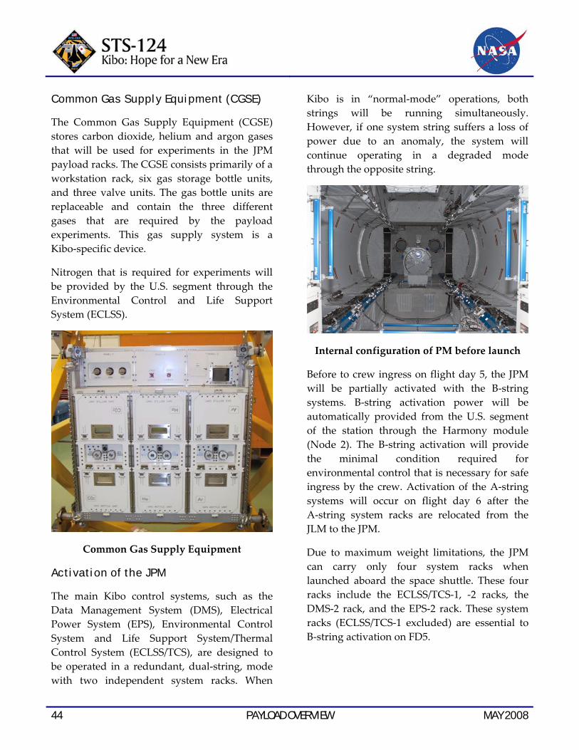
Common Gas Supply Equipment (CGSE)
The Common Gas Supply Equipment (CGSE) stores carbon dioxide, helium and argon gases that will be used for experiments in the JPM payload racks. The CGSE consists primarily of a workstation rack, six gas storage bottle units, and three valve units. The gas bottle units are replaceable and contain the three different gases that are required by the payload experiments. This gas supply system is a Kibo‐specific device.
Nitrogen that is required for experiments will be provided by the U.S. segment through the Environmental Control and Life Support System (ECLSS).
Common Gas Supply Equipment
Activation of the JPM
The main Kibo control systems, such as the Data Management System (DMS), Electrical Power System (EPS), Environmental Control System and Life Support System/Thermal Control System (ECLSS/TCS), are designed to be operated in a redundant, dual‐string, mode with two independent system racks. When
Kibo is in “normal‐mode” operations, both strings will be running simultaneously. However, if one system string suffers a loss of power due to an anomaly, the system will continue operating in a degraded mode through the opposite string.
Internal configuration of PM before launch
Before to crew ingress on flight day 5, the JPM will be partially activated with the B‐string systems. B‐string activation power will be automatically provided from the U.S. segment of the station through the Harmony module (Node 2). The B‐string activation will provide the minimal condition required for environmental control that is necessary for safe ingress by the crew. Activation of the A‐string systems will occur on flight day 6 after the A‐string system racks are relocated from the JLM to the JPM.
Due to maximum weight limitations, the JPM can carry only four system racks when launched aboard the space shuttle. These four racks include the ECLSS/TCS‐1, ‐2 racks, the DMS‐2 rack, and the EPS‐2 rack. These system racks (ECLSS/TCS‐1 excluded) are essential to B‐string activation on FD5.

MAY 2008 PAYLOAD OVERVIEW 45
Once the B‐string is activated, the network between the ground and Kibo will be established and command capability from the Space Station Integration and Promotion Center (SSIPC) at Tsukuba will be enabled. From this point forward, JAXA will maintain control of Kibo from the ground.
Once the SSIPC has confirmed the status of the B‐string activation, the crew on board the space station will open the hatch and enter the JPM. However, at this stage, Kibo system redundancy is not fully ensured, and crew activity inside the module may be restricted.
Eight racks were delivered to the station during the STS‐123 mission. These racks, which have been stored in the JLM during the 1J/A stage, are scheduled to be transferred and installed in the JPM by the end of flight day 6.
The system racks include the JEM Remote Manipulator System (JEMRMS) rack, EPS‐1 rack, DMS‐1 rack, Work Station (WS) rack, Inter‐orbit Communication System (ICS) rack and JEM Resupply Stowage Rack (JRSR). Once these racks are installed in their respective positions, the A‐string activation (with EPS‐1 and DMS‐1) will be enabled, and the JPM will be fully functional. As a result, flight day 6 will be the busiest, most critical day of the mission as there are several “must‐do” events, including rack transfer, spacewalk No. 2, and A‐string activation from the SSIPC.
After system rack transfer and activation, the JAXA payload racks (SAIBO and RYUTAI) will be transferred to the JPM. The payload racks are required to be installed in the JPM before
the relocation of the JLM scheduled on flight day 7.
Once all racks have been transferred, the relocation of the JLM will be performed; the power and utility cables that connected the JLM and the Harmony module (Node 2) will be removed, the hatches of the JLM and Harmony will be closed, and then the JLM will be moved to the zenith CBM port of the JPM by the SSRMS.
Once the JLM relocation is complete, the JEMRMS‐activation tasks (power‐up, partial deployment, full deployment and brake test) will begin.
PAYLOAD RACKS ABOARD KIBO
JAXA’s two payload racks include a biological experiment rack called “SAIBO” and a fluid science experiment rack called “RYUTAI.” Both racks were delivered to the station during the STS‐123 mission. During the STS‐124 mission, these payload racks will be transferred and installed in the JPM. NASA’s three payload racks, currently housed in the Destiny module, are scheduled to be transferred and installed in the JPM after the shuttle departs.
The experiments housed in the SAIBO and RYUTAI racks will be controlled by the station crew, or remotely controlled by the respective rack officers on duty at the User Operations Area at TKSC. The rack officer receives station telemetry and will regularly check the status of the experiment racks, including integrity, temperature control and the working conditions of the science experiments.

46 PAYLOAD OVERVIEW MAY 2008
Location of SAIBO rack in the Kibo Pressurized Module SAIBO Rack
The SAIBO (pronounced sigh‐boe, which means biologic cell) rack was delivered to the station aboard space shuttle Endeavour during the STS‐123 (1J/A) mission. SAIBO is a JAXA payload rack that accommodates the Clean Bench (CB) and Cell Biology Experiment Facility (CBEF). The SAIBO rack provides structural interfaces, power, data, cooling, water and other items required to operate these microgravity experiments on board the station. The SAIBO rack will be transferred to the JPM during the STS‐124 mission.
SAIBO Rack
The SAIBO rack accommodates experiments that will be used for diverse life science research, including cultivation of plant and animal cells in both microgravity and controlled gravity (0.1 G to 2.0 G) conditions.
In addition, germ‐free handling of test articles and microscopic analysis of cells via telemetry commands from the ground can be performed.
SAIBO Rack
MAY 2008 PAYLOAD OVERVIEW 47
SAIBO experiment rack details
The Clean Bench
The Clean Bench (CB) provides a germ‐free environment for life science and biotechnological experiments. The CB has a specially designed microscope that provides bright‐field, phase‐contrast and fluorescence modes. The objective lens can be switched among four magnification levels (4x, 10x, 20x, 40x).
Cell Biology Experiment Facility
The Cell Biology Experiment Facility (CBEF) provides an incubation environment where the temperature, humidity and carbon dioxide levels are controlled. The CBEF has a centrifuge chamber that generates artificial gravity, thus enabling simultaneous experiments in both microgravity and controlled gravity conditions.
Centrifuge Chamber
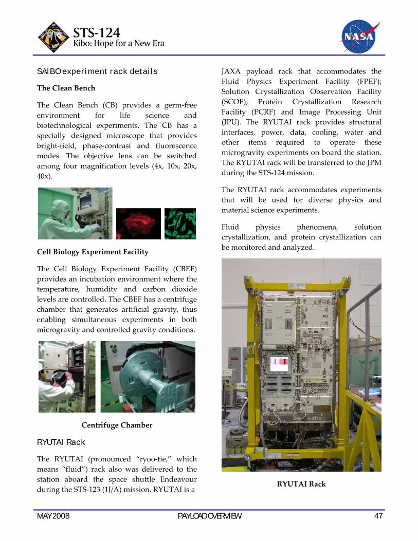
RYUTAI Rack
The RYUTAI (pronounced “ryoo‐tie,” which means “fluid”) rack also was delivered to the station aboard the space shuttle Endeavour during the STS‐123 (1J/A) mission. RYUTAI is a
JAXA payload rack that accommodates the Fluid Physics Experiment Facility (FPEF); Solution Crystallization Observation Facility (SCOF); Protein Crystallization Research Facility (PCRF) and Image Processing Unit (IPU). The RYUTAI rack provides structural interfaces, power, data, cooling, water and other items required to operate these microgravity experiments on board the station. The RYUTAI rack will be transferred to the JPM during the STS‐124 mission.
The RYUTAI rack accommodates experiments that will be used for diverse physics and material science experiments.
Fluid physics phenomena, solution crystallization, and protein crystallization can be monitored and analyzed.
RYUTAI Rack

48 PAYLOAD OVERVIEW MAY 2008
Location of RYUTAI rack in the Kibo Pressurized Module
RYUTAI experiment rack details:
Fluid Physics Experiment Facility
The Fluid Physics Experiment Facility (FPEF) is a platform for conducting fluid physics experiments at ambient temperature in a microgravity environment. Under these condi‐tions, the effects of thermal convection are lower than on Earth, and the effects of gravity on the free surface of a liquid are significantly reduced. Thus, Marangoni convection (convec‐tion attributed to differences between surface tensions) can be observed in a fluid. The prime objective of the FPEF is to investigate the phenomenon of Marangoni convection in a space environment, which affects things such as the growth of semiconductor crystals.
Liquid bridge formed under the microgravity environment
Solution Crystallization Observation Facility and Protein Crystallization Research Facility
The Solution Crystallization Observation Facility (SCOF) and Protein Crystallization Research Facility (PCRF) provide facilities for conducting basic research on crystal and protein growth, in various solutions, in a space environment. The SCOF is designed to grow solution crystals, and the PCRF is designed to grow high‐quality protein crystals. Experiment temperature and pressure conditions can be controlled, and in‐situ observations can be performed while the crystals are growing.
MAY 2008 PAYLOAD OVERVIEW 49
Image Processing Unit
The Image Processing Unit (IPU) receives image data from various experiment equipment in Kibo, encodes the data, and then transfers the data to the Kibo system lines. The IPU also records experiment image data on a hard disk in the Video Recording Unit (VRU) systems when real‐time data downlink is not available. The main functions of the IPU are to maintain various interfaces with Kibo systems and experiment equipment, to receive and decode six channels of independent motion video signals simultaneously, and to record video
signals on the hard disk with six digital VRUs continuously.
KIBO MISSION CONTROL CENTER
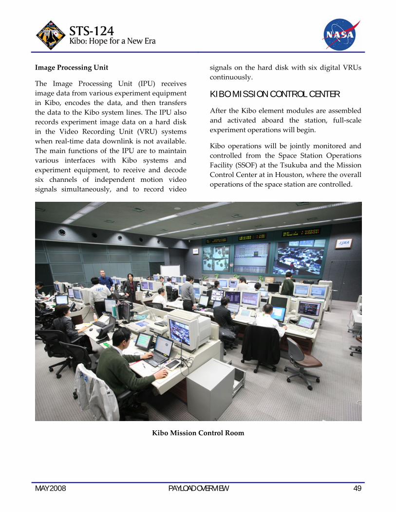
After the Kibo element modules are assembled and activated aboard the station, full‐scale experiment operations will begin.
Kibo operations will be jointly monitored and controlled from the Space Station Operations Facility (SSOF) at the Tsukuba and the Mission Control Center at in Houston, where the overall operations of the space station are controlled.
Kibo Mission Control Room

50 PAYLOAD OVERVIEW MAY 2008
JAXA FLIGHT CONTROL TEAM
The JAXA Flight Control Team consists of flight directors and more than 50 flight controllers assigned to 10 technical disciplines required to support Kibo flight operations. The flight director oversees and directs the team, and the flight controllers possess specialized expertise on all Kibo systems. The team will monitor and control Kibo around the clock in a three‐shift per day schedule.
Once Kibo is operational in orbit, the team will monitor the status of command uplinks, data downlinks, system payloads and experiments aboard Kibo. The team will have the capability of making real‐time operations planning changes, and can communicate directly with the crew aboard Kibo and the various international partner mission control centers around the world. The team will troubleshoot problems or anomalies that may occur aboard Kibo during flight operations.
The team organizes and conducts mission‐specific training which accurately simulates actual Kibo flight operations. The team is responsible for the preparation and evaluation of all plans and procedures that will be performed by the crew aboard Kibo, and by controllers on the ground. In addition, the team regularly conducts off‐nominal and contingency training for all certified flight controllers and candidate flight controllers.
The roles of the respective sections of JFCT are as follows:
JAXA Flight Director
The JAXA Flight Director is the leader of the team. J‐Flight will direct the overall operation of Kibo, including operations planning, system
and experiment operations, and other tasks performed by the crew aboard Kibo.
The flight controllers assigned to each control section must ensure that the J‐Flight is given the current status of every detail of Kibo operations.
STS‐124 (1J) Lead J‐Flight is responsible for the crew safety in the Kibo module, and takes the leading role to integrate the mission which includes assembly and activation of the Kibo JPM and the JEMRMS.
STS‐124 Lead J‐Flight Yoshio Tokaku (left) and STS‐124 NASA Lead Flight Director
Annette Hasbrook (right)
Control and Network Systems, Electrical Power, and ICS Communication Officer
The Control and Network Systems, Electrical Power, and ICS Communication Officer (CANSEI) is responsible for Kibo flight control, network systems, electrical power and ICS communications. CANSEI will monitor the control status of on‐board computers, network systems, and electrical power systems through data downlinked from Kibo on a real‐time basis.
Fluid and Thermal Officer
The Fluid and Thermal Officer (Flat) is responsible for monitoring the status of the ECLSS and the TCS, which regulate the heat

MAY 2008 PAYLOAD OVERVIEW 51
generated by the equipment aboard Kibo. These systems will be monitored through telemetry data downlinked from Kibo on a real‐time basis.
Kibo Robotics Officer
The Kibo Robotics Officer (Kibott) is responsible for the overall operation of the Kibo robotic arm systems, scientific airlock, and other associated mechanisms. During robotic arm and airlock operations, KIBOTT will prepare and monitor the related systems necessary for the flight crew to perform the appropriate tasks aboard Kibo.
Operations Planner
The Operations Planner (J‐Plan) is responsible for planning the actual flight operations. When Kibo is in a flight operations mode, J‐Plan will monitor the status and progress of Kibo operations and, if necessary, will amend or modify the operation plans as required.
System Element Investigation and Integration Officer
The System Element Investigation and Integration Officer (Senin) is responsible for Kibo’s system elements. Senin will monitor and ensure that each Kibo system is running smoothly and will integrate all systems information provided by each flight control section.
Tsukuba Ground Controller
The Tsukuba Ground Controller is responsible for the overall operation and maintenance of the ground support facilities that are essential for Kibo flight operations. This includes the operations control systems and the operations network systems.
JEM Communicator
The JEM Communicator (J‐Com) is responsible for voice communications with the crew aboard Kibo. J‐Com will communicate all essential information to the crew for operating Kibo systems and experiments, and/or respond to Kibo‐specific inquiries from the crew.
Astronaut Related IVA and Equipment Support
Astronaut Related IVA and Equipment Support (ARIES) is responsible for IVA operations aboard Kibo. ARIES will manage the tools and other IVA‐related support equipment on Kibo.
JEM Payload Officer
The JEM Payload officer (JEM Payloads) is responsible for Kibo’s experiment payload operations, and will coordinate payload activities with the primary investigators of each respective experiment.
JAXA Extravehicular Activity
JAXA Extravehicular Activity (JAXA EVA) is responsible for Kibo‐related EVA operations and will provide technical support to the crew members who perform Kibo‐related spacewalks.
Note: The JAXA spacewalk console will not be in the Space Station Operations Facility at the Tsukuba. Instead, the JAXA spacewalk flight controllers will be stationed at NASA’s JSC.
JEM ENGINEERING TEAM
The JEM Engineering Team (JET) is responsible for providing technical support to the flight control team and technical evaluation of real‐ time data and pre‐and post‐flight analysis. JET consists of the JET lead, electrical subsystem, fluid subsystem and IVA engineers who are

52 PAYLOAD OVERVIEW MAY 2008
members of the JEM Development Project Team. JET engineers also work in the NASA Mission Evaluation Room at NASA JSC in order to perform joint troubleshooting and anomaly resolution.
TSUKUBA SPACE CENTER
The Tsukuba Space Center is JAXA’s largest space development and utilization research complex. As Japan’s primary site for human spaceflight research and operations, it operates the following facilities in support of the Kibo mission.
Space Station Test Building
Comprehensive Kibo system tests were conducted in this building. The main purpose of the tests was to verify function, physical interface and performance of the entire Kibo system including all the associated elements. In addition, subsystems, payloads, and ground support equipment were all tested in this
building. Once Kibo operations begin aboard the station, engineering support will be provided from this building.
S p a c e E x p e ri m e n t L a b o r a t o r y ( S E L ) The following activities are conducted in this building:
• Development of technologies required for space experiments
• Preparation of Kibo experiment programs
• Experiment data analysis and support

MAY 2008 PAYLOAD OVERVIEW 53
Astronaut Training Facility (ATF)
The following activities are conducted in this building:
• JAXA astronaut candidate training
• Astronaut training and health care
This building is a primary site for Japan’s space medicine research.
Weightless Environment Test Building (WET)
This facility provides a simulated weightless environment using water buoyancy for astronaut training. Design verification tests on various Kibo element modules and development of preliminary EVA procedures were conducted in this facility.
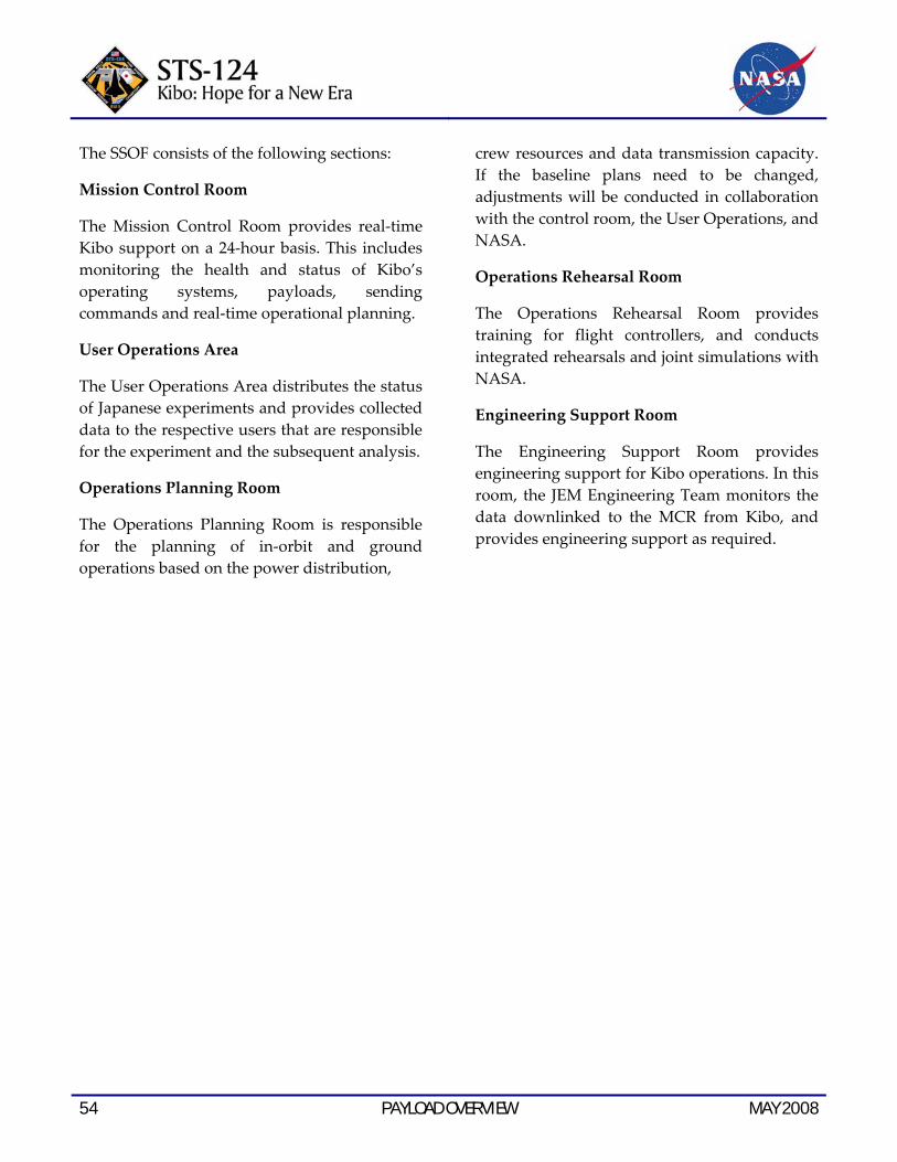
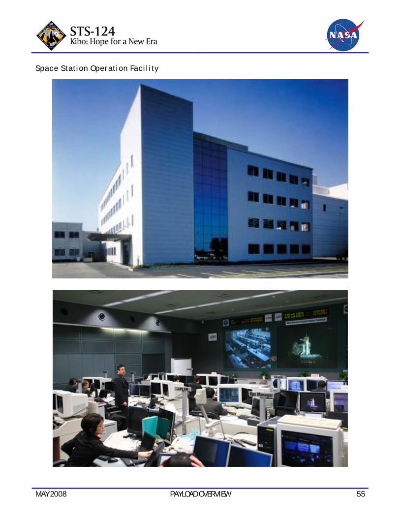
SPACE STATION OPERATION FACILITY
The Space Station Operation Facility (SSOF) is responsible for controlling Kibo operations. At the SSOF, operation of Kibo systems and payloads are supervised and Kibo operation plans are prepared in cooperation with NASA’s Space Station Control Center (SSCC) and Payload Operation Integration Center (POIC).
The SSOF is responsible for the following:
• Monitoring and controlling Kibo operating systems
• Monitoring and controlling Japanese experiments on Kibo
• Implementing operation plans
• Supporting launch preparation
54 PAYLOAD OVERVIEW MAY 2008
The SSOF consists of the following sections:
Mission Control Room
The Mission Control Room provides real‐time Kibo support on a 24‐hour basis. This includes monitoring the health and status of Kibo’s operating systems, payloads, sending commands and real‐time operational planning.
User Operations Area
The User Operations Area distributes the status of Japanese experiments and provides collected data to the respective users that are responsible for the experiment and the subsequent analysis.
Operations Planning Room
The Operations Planning Room is responsible for the planning of in‐orbit and ground operations based on the power distribution,
crew resources and data transmission capacity. If the baseline plans need to be changed, adjustments will be conducted in collaboration with the control room, the User Operations, and NASA.
Operations Rehearsal Room
The Operations Rehearsal Room provides training for flight controllers, and conducts integrated rehearsals and joint simulations with NASA.
Engineering Support Room
The Engineering Support Room provides engineering support for Kibo operations. In this room, the JEM Engineering Team monitors the data downlinked to the MCR from Kibo, and provides engineering support as required.
MAY 2008 PAYLOAD OVERVIEW 55
Space Station Operation Facility

56 PAYLOAD OVERVIEW MAY 2008
This page intentionally left blank.
MAY 2008 RENDEZVOUS & DOCKING 57
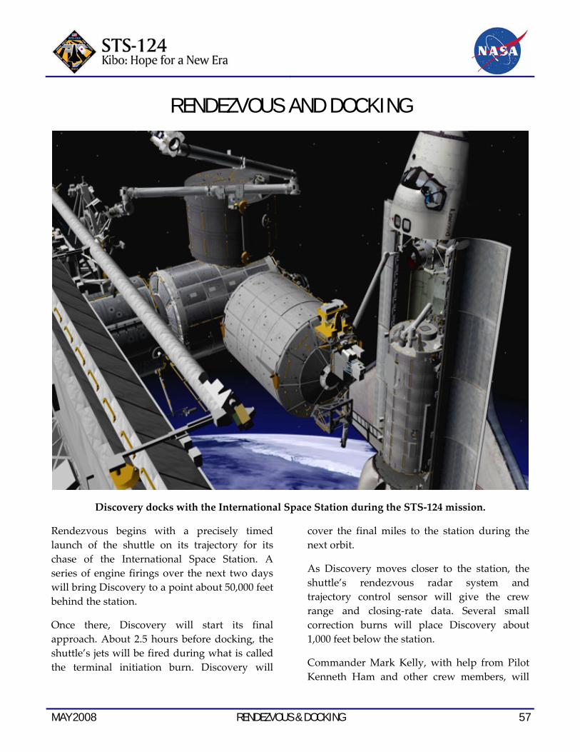
RENDEZVOUS AND DOCKING
Discovery docks with the International Space Station during the STS‐124 mission.
Rendezvous begins with a precisely timed launch of the shuttle on its trajectory for its chase of the International Space Station. A series of engine firings over the next two days will bring Discovery to a point about 50,000 feet behind the station.
Once there, Discovery will start its final approach. About 2.5 hours before docking, the shuttle’s jets will be fired during what is called the terminal initiation burn. Discovery will
cover the final miles to the station during the next orbit.
As Discovery moves closer to the station, the shuttle’s rendezvous radar system and trajectory control sensor will give the crew range and closing‐rate data. Several small correction burns will place Discovery about 1,000 feet below the station.
Commander Mark Kelly, with help from Pilot Kenneth Ham and other crew members, will

58 RENDEZVOUS & DOCKING MAY 2008
manually fly the shuttle for the remainder of the approach and docking.
Kelly will stop Discovery about 600 feet below the station. Once he determines there is proper lighting, he will maneuver Discovery through a nine‐minute back flip called the Rendezvous Pitch Maneuver. That allows the station crew to take as many as 300 digital pictures of the shuttle’s heat shield.
Station crew members will use digital cameras with 400 mm and 800 mm lenses to photograph Discovery’s upper and bottom surfaces through windows of the Zvezda Service Module. The
400 mm lens provides up to 3‐inch resolution and the 800 mm lens up to 1‐inch resolution.
The photography is one of several techniques used to inspect the shuttle’s thermal protection system for possible damage. Areas of special interest include the thermal protection tiles, the reinforced carbon‐carbon of the nose and leading edges of the wings, landing gear doors and the elevon cove.
The photos will be downlinked through the station’s Ku‐band communications system for analysis by systems engineers and mission managers.
Discovery conducts the rendezvous pitch maneuver that enables station astronauts to photograph the orbiter as one technique of inspecting the thermal protection system.
MAY 2008 RENDEZVOUS & DOCKING 59
When Discovery completes its back flip, it will be back where it started, with its payload bay facing the station.
Kelly then will fly Discovery through a quarter circle to a position about 400 feet directly in front of the station. From that point he will begin the final approach to docking to the Pressurized Mating Adapter 2 at the forward end of the Harmony node.
The shuttle crew members operate laptop computers processing the navigational data, the laser range systems and Discovery’s docking mechanism.
Using a video camera mounted in the center of the ODS, Kelly will line up the docking ports of the two spacecraft. If necessary, he will pause 30 feet from the station to ensure proper alignment of the docking mechanisms.
He will maintain the shuttle’s speed relative to the station at about one‐tenth of a foot per second, while both Discovery and the station are moving at about 17,500 mph. He will keep the docking mechanisms aligned to a tolerance of three inches.
When Discovery makes contact with the station, preliminary latches will automatically attach the two spacecraft. The shuttle’s steering jets will be deactivated to reduce the forces acting at the docking interface. Shock absorber springs in the docking mechanism will dampen any relative motion between the shuttle and station.
Once motion between the shuttle and the station has been stopped, the docking ring will be retracted to close a final set of latches between the two vehicles.
UNDOCKING, SEPARATION AND DEPARTURE
At undocking time, the hooks and latches will be opened, and springs will push the shuttle away from the station. Discovery’s steering jets will be shut off to avoid any inadvertent firings during the initial separation.
Once Discovery is about two feet from the station and the docking devices are clear of one another, Ham will turn the steering jets back on and will manually control Discovery within a tight corridor as the shuttle separates from the station.
Discovery will move to a distance of about 450 feet, where Ham will begin to fly around the station in its new configuration. This maneuver will occur only if propellant margins and mission timeline activities permit.
Once Discovery completes 1.5 revolutions of the complex, Ham will fire Discovery’s jets to leave the area. The shuttle will move about 46 miles from the station and remain there while ground teams analyze data from the late inspection of the shuttle’s heat shield. The distance is close enough to allow the shuttle to return to the station in the unlikely event that the heat shield is damaged, preventing the shuttle’s safe re‐entry.
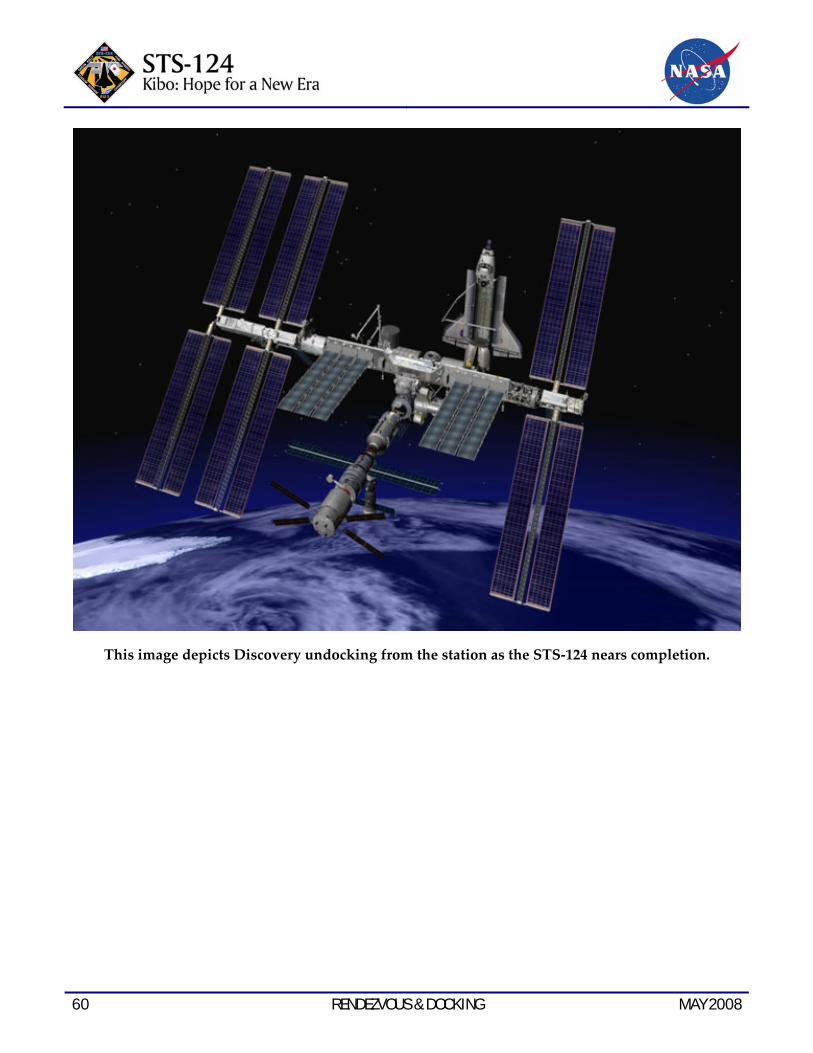
60 RENDEZVOUS & DOCKING MAY 2008
This image depicts Discovery undocking from the station as the STS‐124 nears completion.

MAY 2008 SPACEWALKS 61
SPACEWALKS The three spacewalks of the STS‐124 mission will help install the largest laboratory the space station has ever seen. They also will keep the exterior of the station cool, help restore the station to its full power‐generating capability, and return the 50‐foot boom left during the last mission to the space station.
The spacewalks, also known as extravehicular activities, or EVAs, will be performed on the
fourth, sixth and ninth days by Mission Specialists Mike Fossum and Ron Garan. Fossum, the lead spacewalker, will be wearing a spacesuit marked with solid red stripes. He is a veteran spacewalker, with three spacewalks performed during the STS‐121 mission under his belt. Garan, a first‐time spacewalker, will wear an all white suit.
Spacewalkers will wear gloves fashioned with thumb patches to prevent glove damage seen on recent missions.

62 SPACEWALKS MAY 2008
To help prevent the glove damage seen in recent missions from recurring, both spacewalkers will wear gloves with reinforced patches on the thumb and index finger for the first time. The patches are made of the same cut‐resistant Vectran material already used in the palm of the gloves, but in a much tighter weave. In this form, the fabric is called TurtleSkin. TurtleSkin patches were sewn onto the gloves below the tip of the thumb and index finger, and an extra strip of the glove’s rubbery outer layer was added over the TurtleSkin to provide grip.
Tests have shown that this TurtleSkin weave greatly increases the Vectran’s strength. It is up to four times more resistant to being damaged than the normal weave.
Pilot Ken Ham will be the intravehicular officer, or spacewalk choreographer. Mission Specialists Karen Nyberg, Akihiko Hoshide and Greg Chamitoff will be operating the shuttle and station robotic arms. Nyberg is expected to be the first person to operate three different robotic arms in space, after the new Japanese laboratory robotic arm is deployed following the third spacewalk.
Made of the same material already used in the palm of the gloves, but in a much tighter weave, the fabric is called TurtleSkin. The patches were sewn onto the gloves below the tip of the thumb and index finger. A strip of the glove’s rubbery outer layer was added
over the TurtleSkin to provide grip.
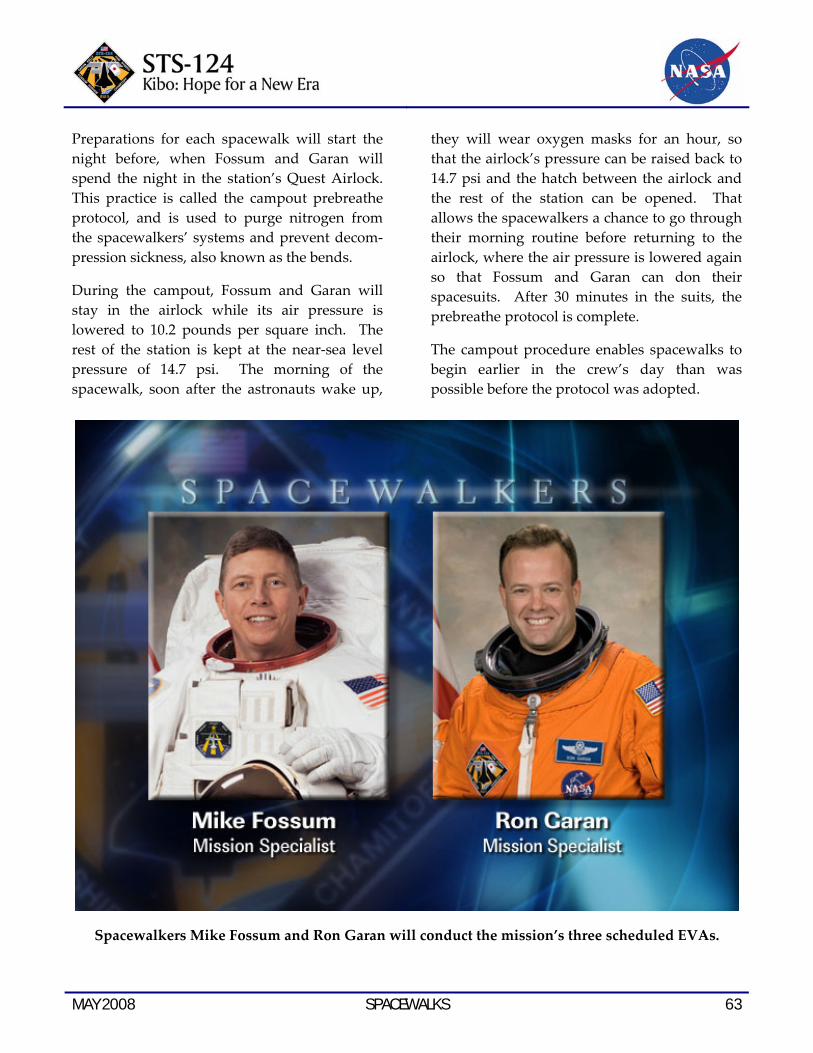
MAY 2008 SPACEWALKS 63
Preparations for each spacewalk will start the night before, when Fossum and Garan will spend the night in the station’s Quest Airlock. This practice is called the campout prebreathe protocol, and is used to purge nitrogen from the spacewalkers’ systems and prevent decom‐pression sickness, also known as the bends.
During the campout, Fossum and Garan will stay in the airlock while its air pressure is lowered to 10.2 pounds per square inch. The rest of the station is kept at the near‐sea level pressure of 14.7 psi. The morning of the spacewalk, soon after the astronauts wake up,
they will wear oxygen masks for an hour, so that the airlock’s pressure can be raised back to 14.7 psi and the hatch between the airlock and the rest of the station can be opened. That allows the spacewalkers a chance to go through their morning routine before returning to the airlock, where the air pressure is lowered again so that Fossum and Garan can don their spacesuits. After 30 minutes in the suits, the prebreathe protocol is complete.
The campout procedure enables spacewalks to begin earlier in the crew’s day than was possible before the protocol was adopted.
Spacewalkers Mike Fossum and Ron Garan will conduct the mission’s three scheduled EVAs.
64 SPACEWALKS MAY 2008
EVA-1
Duration: 6 hours, 30 minutes
EVA Operations:
• Release the straps holding the shuttle robotic arm’s elbow joint camera down for launch
• Transfer the Orbiter Boom Sensor System from the station’s starboard truss to the shuttle
• Prepare the Kibo laboratory for installation
• Replace one of the 12 trundle bearing assemblies on the starboard solar alpha rotary joint
• Inspect damage to the solar alpha rotary joint
• Test cleaning methods for use on the solar alpha rotary joint’s race ring
The first objective is to transfer the OBSS left after the previous shuttle mission from the station’s truss to space shuttle Discovery. Most of the tasks will fall to Garan, who will be releasing the stanchions holding the boom to the truss and removing a bag that has been protecting the boom’s sensor package. Just before the station’s robotic arm takes control of the boom and hands it off to the shuttle’s robotic arm, Fossum will detach the keep‐alive umbilical that has been providing the boom’s systems with power while stowed. The boom will be used later in the mission to inspect the shuttle’s heat shield.
Next, the spacewalkers will prepare the Kibo laboratory for installation. While Garan is working on the boom, Fossum will inspect the Harmony Node’s left side active common berthing mechanism to ensure that it’s ready to
attach to Kibo. He’ll also open a window cover to provide the crew inside with a good view of the installation.
After the boom work is done, Garan and Fossum will work together in the shuttle’s cargo bay to remove contamination covers from the surface where the module will connect to Harmony. Fossum also will disconnect the heater cables connecting the module to the shuttle and remove three bolts that lock the shutters of Kibo’s forward window in place for launch.
The spacewalkers’ final tasks of the spacewalk will take them to the station’s starboard solar alpha rotary joint. The 10‐foot‐wide rotary joint, which allows the station’s starboard solar arrays to rotate and track the sun, began experiencing increased vibration and power usage in the fall of 2007. Inspections turned up metal shavings inside the joint. One of the joint’s 12 trundle bearing assemblies, which allow the joint’s outboard ring to rotate around its inboard ring, was removed.
Garan will install a replacement for that trundle bearing assembly. Meanwhile, Fossum will inspect a potentially damaged area on the joint to determine whether there is debris sitting on the surface of the metal, or a divot in the metal. A similar inspection was performed during STS‐123, but Fossum will use sharper tools to give him more tactile feedback.
Fossum also will try out techniques for cleaning the surface of the joint’s race ring. First, he’ll try removing a section of the debris, using a putty knife as a scraper. Next, he will apply grease to the surface and then try the scraper again. And finally, Fossum will try using a wipe and grease to ascertain if a scraper is actually needed.

MAY 2008 SPACEWALKS 65
Astronauts Ron Garan and Mike Fossum (partially obscured), both STS‐124 mission specialists, are about to be submerged in the waters of the Neutral
Buoyancy Laboratory near JSC.
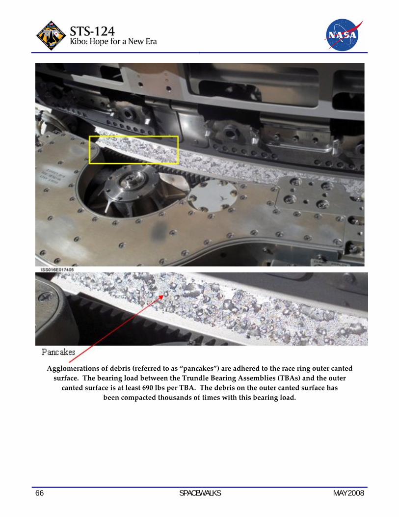
66 SPACEWALKS MAY 2008
Agglomerations of debris (referred to as “pancakes”) are adhered to the race ring outer canted surface. The bearing load between the Trundle Bearing Assemblies (TBAs) and the outer canted surface is at least 690 lbs per TBA. The debris on the outer canted surface has
been compacted thousands of times with this bearing load.
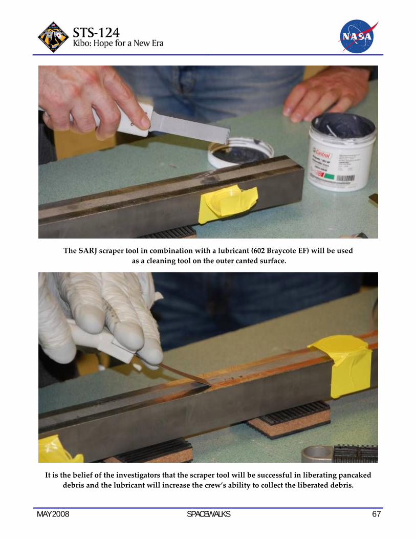
MAY 2008 SPACEWALKS 67
The SARJ scraper tool in combination with a lubricant (602 Braycote EF) will be used as a cleaning tool on the outer canted surface.
It is the belief of the investigators that the scraper tool will be successful in liberating pancaked debris and the lubricant will increase the crew’s ability to collect the liberated debris.
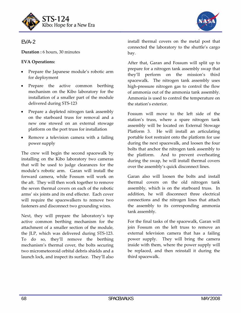
68 SPACEWALKS MAY 2008
EVA-2
Duration : 6 hours, 30 minutes
EVA Operations:
• Prepare the Japanese module’s robotic arm for deployment
• Prepare the active common berthing mechanism on the Kibo laboratory for the installation of a smaller part of the module delivered during STS‐123
• Prepare a depleted nitrogen tank assembly on the starboard truss for removal and a new one stowed on an external stowage platform on the port truss for installation
• Remove a television camera with a failing power supply
The crew will begin the second spacewalk by installing on the Kibo laboratory two cameras that will be used to judge clearances for the module’s robotic arm. Garan will install the forward camera, while Fossum will work on the aft. They will then work together to remove the seven thermal covers on each of the robotic arms’ six joints and its end effecter. Each cover will require the spacewalkers to remove two fasteners and disconnect two grounding wires.
Next, they will prepare the laboratory’s top active common berthing mechanism for the attachment of a smaller section of the module, the JLP, which was delivered during STS‐123. To do so, they’ll remove the berthing mechanism’s thermal cover, the bolts securing two micrometeoroid orbital debris shields and a launch lock, and inspect its surface. They’ll also
install thermal covers on the metal post that connected the laboratory to the shuttle’s cargo bay.
After that, Garan and Fossum will split up to prepare for a nitrogen tank assembly swap that they’ll perform on the mission’s third spacewalk. The nitrogen tank assembly uses high‐pressure nitrogen gas to control the flow of ammonia out of the ammonia tank assembly. Ammonia is used to control the temperature on the station’s exterior.
Fossum will move to the left side of the station’s truss, where a spare nitrogen tank assembly will be located on External Stowage Platform 3. He will install an articulating portable foot restraint onto the platform for use during the next spacewalk, and loosen the four bolts that anchor the nitrogen tank assembly to the platform. And to prevent overheating during the swap, he will install thermal covers over the assembly’s quick disconnect lines.
Garan also will loosen the bolts and install thermal covers on the old nitrogen tank assembly, which is on the starboard truss. In addition, he will disconnect three electrical connections and the nitrogen lines that attach the assembly to its corresponding ammonia tank assembly.
For the final tasks of the spacewalk, Garan will join Fossum on the left truss to remove an external television camera that has a failing power supply. They will bring the camera inside with them, where the power supply will be replaced, and then reinstall it during the third spacewalk.

MAY 2008 SPACEWALKS 69
Astronaut Mike Fossum, STS‐124 mission specialist, dons a training version of his Extravehicular Mobility Unit (EMU) spacesuit before to being submerged in the waters of the Neutral Buoyancy Laboratory (NBL) near JSC. Suit technicians assisted Fossum.
EVA-3
Duration: 6 hours, 20 minutes
EVA Operations:
• Remove and replace the starboard nitrogen tank assembly
• Finish outfitting the Kibo laboratory
• Reinstall repaired television camera removed during the second spacewalk
Replacing the depleted nitrogen tank assembly will require Garan to spend much of his third spacewalk on the station’s robotic arm. He will
start the spacewalk by installing a width extender to increase the robotic arm’s reach, climb into a foot restraint attached to the width extender and remove four bolts holding the old nitrogen tank assembly in place on the starboard truss. After installing a handle on the assembly, he will remove it from the truss and carry it to the external stowage platform, via the robotic arm.
Meanwhile, Fossum will remove the spare nitrogen tank assembly from the platform to make room for the old one, and store it on the other side of the platform. When Garan arrives with the old assembly, Fossum will guide it
70 SPACEWALKS MAY 2008
into place and begin securing it to the platform with four bolts. Once one of the four bolts has been secured, Garan will remove his handle from the old assembly, attach it to the new one and ride the robotic arm back to the starboard truss with the nitrogen tank assembly in tow. He’ll remove his handle, install the bolts to secure it to the truss and connect the necessary electrical link. Then he will get off the robotic arm and move to the back of the truss to connect the assembly’s nitrogen lines to the ammonia tank assembly.
Meanwhile, Fossum will finish securing the old nitrogen assembly and move to the Kibo module to finish outfitting it. He will remove launch locks and thermal covers from the two
cameras on the module’s robotic arm, as well as the launch locks on the module’s aft window. The window had been blocked by the robotic arm during the first spacewalk, when he removed the launch locks on the module’s forward window. He will then deploy two micrometeoroid debris shields on either side of the connection between the larger laboratory module and the recently relocated experiments logistics module.
Once that’s done, Fossum will return to the airlock to retrieve the external television camera with its new power supply. He will meet Garan back on the port truss, where they will reinstall the camera.

MAY 2008 EXPERIMENTS 71
EXPERIMENTS The space shuttle and the International Space Station have an integrated research program that optimizes use of shuttle crew members and long‐duration space station crew members to address research questions in a variety of disciplines.
For information on science on the station, visit:
http://www.nasa.gov/mission_pages/station/science/index.html
or
http://iss-science.jsc.nasa.gov/index.cfm
Detailed information is located at:
http://www.nasa.gov/mission_pages/station/science/experiments/Expedition.html
SHORT-DURATION U.S. INTEGRATED RESEARCH TO BE COMPLETED DURING STS-124/1J (4)
Validation of Procedures for Monitoring Crew Member Immune Function – Short Duration Biological Investigation (Integrated Immune‐SDBI) will assess the clinical risks resulting from the adverse effects of spaceflight on the human immune system and will validate a flight‐compatible immune monitoring strategy. The experiment entails collecting and analyzing blood, urine and saliva samples from crew members before, during and after space flight to monitor changes in the immune system.
Maui Analysis of Upper Atmospheric Injections (MAUI) will observe the space shuttle engine exhaust plumes from the Maui Space Surveillance Site in Hawaii. The
observations will occur when the space shuttle fires its engines at night or twilight. A telescope and all‐sky imagers will take images and data while the space shuttle flies over the Maui site. The images will be analyzed to better understand the interaction between the spacecraft plume and the upper atmosphere of Earth
National Lab Pathfinder ‐ Vaccine ‐ 1B (NLP‐Vaccine‐1B) is a commercial payload serving as a pathfinder experiment demonstrating the use of the space station as a National Laboratory after station assembly is complete. NLP‐Vaccine‐1B contains a pathogenic (disease causing) organism, which will be grown in space and later examined to see if spaceflight conditions affect its virulence (infection potential). This information has potential applications for vaccine development to prevent infections on Earth and in microgravity.
Sleep‐Wake Actigraphy and Light Exposure During Spaceflight ‐ Short (Sleep‐Short) will examine the effects of spaceflight on the sleep‐wake cycles of the astronauts during space shuttle missions. Advancing state‐of‐the‐art technology for monitoring, diagnosing and assessing treatment of sleep patterns is vital to treating insomnia on Earth and in space.
SAMPLES RETURNING FROM ISS ON STS-124
Bisphosphonates as a Countermeasure to Space Flight Induced Bone Loss (Bisphosphonates) will study the effectiveness of bisphosphonates (medications that block the

72 EXPERIMENTS MAY 2008
breakdown of bone) used in conjunction with the routine in‐flight exercise program to protect space station crew members from the regional decreases in bone mineral density documented on previous station missions.
Commercial Generic Bioprocessing Apparatus Science Insert ‐ 02 (CSI‐02) is an educational payload designed to interest middle school students in science, technology, engineering and math by participating in near real‐time research conducted on board the space station. Students observe four experiments through data and imagery downlinked and distributed directly into the classroom via the Internet. The first experiment examined seed germination and plant development in microgravity. The second experiment looked at yeast cells adaptation to the space environment. The third experiment observed plant cell cultures and the fourth a silicate garden. The experiments conducted for CSI‐02 are designed primarily to meet education objectives; however, to the maximum extent possible, meaningful scientific research is conducted to generate new knowledge into gravity‐dependent biological processes and to support future plans for human space exploration. CSI‐02 has the potential to impact more than 15,000 middle school and high school students.
Coarsening in Solid Liquid Mixtures‐2 (CSLM‐2) examines the kinetics of competitive particle growth within a liquid metal matrix. During this process, small particles of tin suspended in a liquid tin‐lead matrix shrink by losing atoms to larger particles of tin, causing the larger particles to grow (coarsen). This study defines the mechanisms and rates of coarsening in the absence of gravitational settling. This work has direct applications to metal alloy manufacturing on Earth, including materials critical for aerospace applications
(e.g., the production of better aluminum alloys for turbine blades).
Validation of Procedures for Monitoring Crew Member Immune Function (Integrated Immune) will assess the clinical risks resulting from the adverse effects of spaceflight on the human immune system and will validate a flight‐compatible immune monitoring strategy. Researchers collect and analyze blood, urine and saliva samples from crew members before, during and after space flight to monitor changes in the immune system.
Nutritional Status Assessment (Nutrition) is the most comprehensive in‐flight study done by NASA to date of human physiologic changes during long‐duration spaceflight; this includes measures of bone metabolism, oxidative damage, nutritional assessments, and hormonal changes. This study will impact both the definition of nutritional requirements and development of food systems for future space exploration missions to the moon and Mars. This experiment also helps to understand the impact of countermeasures (exercise and pharmaceuticals) on nutritional status and nutrient requirements for astronauts.
The National Aeronautics and Space Administration Biological Specimen Repository (Repository) is a storage bank that is used to maintain biological specimens over extended periods of time and under well‐controlled conditions. Samples from the space station, including blood and urine, will be collected, processed and archived during the preflight, in‐flight and postflight phases of the spacestation missions. This investigation has been developed to archive biosamples for use as a resource for future spaceflight‐related research.
MAY 2008 EXPERIMENTS 73
Simulation of Geophysical Fluid Flow under Microgravity (Geoflow) is an ESA investigation for the Fluid Science Laboratory (FSL) on the space station. Geoflow will study thermal convection and flow in a viscous, incompressible fluid contained in the gap between two concentric rotating spheres. The results will be used to model global‐scale flow applicable to the Earth’s atmosphere, oceans, and liquid core.
The Reverse Genetic Approach to Exploring Genes Responsible for Cell Wall Dynamics in Supporting Tissues of Arabidopsis Under Microgravity Conditions and Role of Microtubule‐Membrane‐Cell Wall Continuum in Gravity Resistance in Plants (CWRW) is a pair of investigations that will explore the molecular mechanism by which the cell wall (rigid outermost layer) construction in Arabidopsis thaliana (a small plant of the mustard family) is regulated by gravity, and determine the importance of the structural connections between microtubule, plasma membrane, cell wall as the mechanism of gravity resistance. The results of these JAXA investigations will support future plans to cultivate plants on long‐duration exploration missions.
EXPERIMENTS AND HARDWARE TO BE DELIVERED TO INTERNATIONAL SPACE STATION
Test of Midodrine as a Countermeasure Against Postflight Orthostatic Hypotension ‐ Long (Midodrine‐Long) is a test of the ability
of the drug midodrine to reduce the incidence or severity of orthostatic hypotension. If successful, it will be employed as a countermeasure to the dizziness caused by the blood‐pressure decrease that many astronauts experience upon returning to the Earth’s gravity.
Sleep‐Wake Actigraphy and Light Exposure During Spaceflight‐Long (Sleep‐Long) will examine the effects of spaceflight and ambient light exposure on the sleep‐wake cycles of the crew members during long‐duration stays on the space station.
Passive Dosimeter for Lifescience Experiment in Space (PADLES) measures radiation exposure levels on board the space station. PADLES uses passive and integrating dosimeters to detect radiation levels. These dosimeters are located near the biological experiment facilities and on the end of the JEM, Kibo.
Commercial Payload Program is a suite of commercial investigations sponsored by JAXA.

74 EXPERIMENTS MAY 2008
This page intentionally left blank.

MAY 2008 EXTERNAL TANK 75
EXTERNAL FUEL TANK ET-128 FOR SPACE SHUTTLE MISSION STS-124
External fuel tank ET‐128 is the first in‐line production tank — or the first tank to fly with Return to Flight changes and other improvements incorporated during manufacturing instead of added to the tank post‐production. It also is the first tank to fly with redesigned liquid hydrogen ice frost ramps and liquid oxygen feedline support brackets.
LIQUID HYDROGEN TANK ICE FROST RAMPS
The Space Shuttle Program approved a redesign to the ramps after foam debris loss during previous shuttle flights, and after cracks were discovered during post‐STS‐114 dissections of external tank ET‐120.
The external fuel tank main propulsion system pressurization lines and cable trays are attached along the length of the tank at multiple locations by metal support brackets. They are protected from forming ice and frost during tanking operations by foam protuberances called ice frost ramps. There are 36 ice/frost ramps on the tank, 12 on the liquid oxygen tank, seven on the intertank and 17 on the liquid hydrogen tank. The size and design of each ice frost ramp is dependent upon location. The smaller ramps on the liquid oxygen tank are roughly 1.5 feet long by 1.5 feet wide by 5 inches high and weigh about 12 ounces. The larger ramps on the liquid hydrogen tank are roughly 2 feet long by 2 feet wide by 1 foot high and weigh approximately 1.7 pounds each.
The ice frost ramps on ET‐128 appear identical to ramps on previous tanks, but several design changes have been made at all 17 locations on
the liquid hydrogen tank.
Redesign changes were incorporated into all 17 ice frost ramps on the liquid hydrogen tank (stations Xt 1151 through Xt 2057) to reduce foam loss. They appear identical to the previous design but several changes have been made:
• BX* manual spray foam has replaced PDL* and NCFI* foam in the ramp’s base cutout to reduce debonding and cracking.
• Pressline and cable tray bracket feet corners have been rounded to reduce stresses.
• Shear pin holes have been sealed to reduce leak paths.
* BX is a type of foam used on the tank’s “closeout,” or final areas, and is applied manually or hand‐sprayed. PDL is an acronym for Product Development Laboratory, the first supplier of the foam during the early days of the external tank’s development. PDL foam is hand‐poured foam used for filling odd‐shaped cavities. NCFI foam is used on the aft dome, or bottom, of the liquid hydrogen tank.

76 EXTERNAL TANK MAY 2008
• Isolators were primed to promote adhesion; isolator corners were rounded to help reduce thermal protection system (TPS) stresses.
• BX manual spray applied in bracket pockets to reduce geometric voids.
A similar configuration was flown on STS‐120’s ET‐120 and performed exceptionally well with no debris events observed.
LIQUID OXYGEN FEEDLINE BRACKETS
Because the feedline bracket configuration has the potential for foam and ice debris loss, the Space Shuttle Program approved a redesign that minimizes ice formation in under‐insulated areas and minimizes foam damage or loss due to ice and foam interferences during normal feedline relative motion.
The liquid oxygen tank feedline, approximately 70 feet long and about 17 inches in diameter, carries liquid oxygen from the liquid oxygen tank to the orbiter, where it is distributed internally to the main engines. The feedline is attached to the tank with five brackets that resemble an L‐shaped boomerang. The brackets allow movement, or “articulation,” of the feedline to compensate for propellant flow during fueling on the launch pad, and during detanking. They also take into consideration the external tank thermal expansion and contraction. Liquid oxygen feedline bracket changes include:
• Titanium brackets replace aluminum brackets at four locations, Xt 1129, Xt 1377, Xt 1624 and Xt 1871, to minimize ice formation in under‐insulated areas. The amount of foam required to cover the brackets and the propensity for ice development was reduced. Titanium is
much less thermally conductive than aluminum.
• Zero‐gap/slip plane Teflon material was applied to the upper outboard monoball attachment to eliminate ice adhesion.
• Additional foam was added to the feedline to minimize cold spots and reduce ice.
Redesign changes were incorporated into all 17 ice frost ramps locations on the liquid hydrogen tank (stations 1151 through 2057).
* Station 2057 is located under the umbilical feed for the liquid oxygen tank feedline.
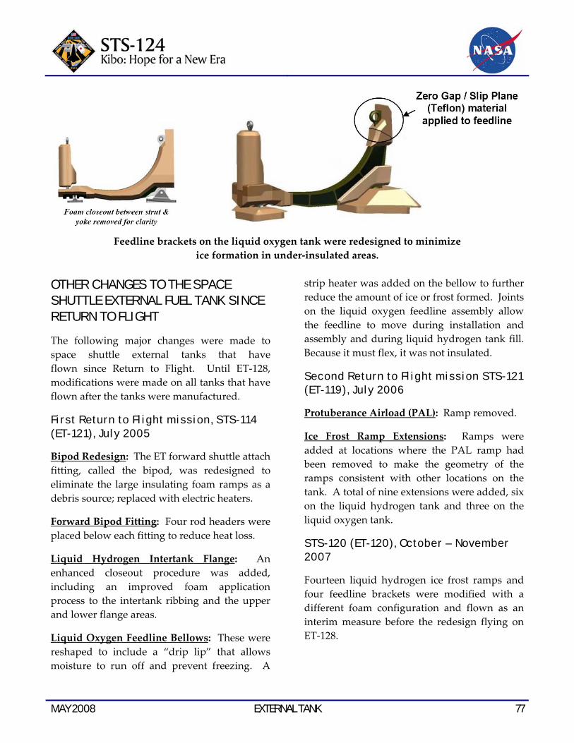
MAY 2008 EXTERNAL TANK 77
Feedline brackets on the liquid oxygen tank were redesigned to minimize
ice formation in under‐insulated areas. OTHER CHANGES TO THE SPACE SHUTTLE EXTERNAL FUEL TANK SINCE RETURN TO FLIGHT
The following major changes were made to space shuttle external tanks that have flown since Return to Flight. Until ET‐128, modifications were made on all tanks that have flown after the tanks were manufactured.
First Return to Flight mission, STS-114 (ET-121) , July 2005
Bipod Redesign: The ET forward shuttle attach fitting, called the bipod, was redesigned to eliminate the large insulating foam ramps as a debris source; replaced with electric heaters.
Forward Bipod Fitting: Four rod headers were placed below each fitting to reduce heat loss.
Liquid Hydrogen Intertank Flange: An enhanced closeout procedure was added, including an improved foam application process to the intertank ribbing and the upper and lower flange areas.
Liquid Oxygen Feedline Bellows: These were reshaped to include a “drip lip” that allows moisture to run off and prevent freezing. A
strip heater was added on the bellow to further reduce the amount of ice or frost formed. Joints on the liquid oxygen feedline assembly allow the feedline to move during installation and assembly and during liquid hydrogen tank fill. Because it must flex, it was not insulated.
Second Return to Fl ight mission STS-121 (ET-119) , July 2006
Protuberance Airload (PAL): Ramp removed.
Ice Frost Ramp Extensions: Ramps were added at locations where the PAL ramp had been removed to make the geometry of the ramps consistent with other locations on the tank. A total of nine extensions were added, six on the liquid hydrogen tank and three on the liquid oxygen tank.
STS-120 (ET-120), October – November 2007
Fourteen liquid hydrogen ice frost ramps and four feedline brackets were modified with a different foam configuration and flown as an interim measure before the redesign flying on ET‐128.

78 EXTERNAL TANK MAY 2008
STS-122 (ET-125), Feb. 7 , 2008
The engine cutoff sensor feed‐through connector on the liquid hydrogen tank was modified on the launch pad after ECO sensor system false readings prevented a December 2007 launch. A modified connector was designed with pins and sockets soldered together. The same configuration has flown on subsequent flights. A team continues to study a possible long‐term fix to the ECO sensor system.
Remaining space shuttle external tanks assigned to space shuttle missions:
ET‐127 – STS‐125
ET‐129 – STS‐126
ET‐130 – STS‐119
ET‐131 – STS‐127
ET‐132 – STS‐128
ET‐133 – STS‐129
ET‐134 – STS‐130
ET‐135 – STS‐131
ET‐136 – STS‐132
ET‐137 – STS‐133
ET‐138 – Tank for a launch on need, or rescue, mission for STS‐133
MAY 2008 SHUTTLE REFERENCE DATA 79
SHUTTLE REFERENCE DATA SHUTTLE ABORT MODES
Redundant Sequence Launch Sequencer (RSLS) Aborts
These occur when the on‐board shuttle computers detect a problem and command a halt in the launch sequence after taking over from the ground launch sequencer and before solid rocket booster ignition.
Ascent Aborts
Selection of an ascent abort mode may become necessary if there is a failure that affects vehicle performance, such as the failure of a space shuttle main engine or an orbital maneuvering system engine. Other failures requiring early termination of a flight, such as a cabin leak, might also require the selection of an abort mode. There are two basic types of ascent abort modes for space shuttle missions: intact aborts and contingency aborts. Intact aborts are designed to provide a safe return of the orbiter to a planned landing site. Contingency aborts are designed to permit flight crew survival following more severe failures when an intact abort is not possible. A contingency abort would generally result in a ditch operation.
Intact Aborts
There are four types of intact aborts: abort to orbit (ATO), abort once around (AOA), transoceanic abort landing (TAL) and return to launch site (RTLS).
Return to Launch Site
The RTLS abort mode is designed to allow the return of the orbiter, crew, and payload to the launch site, KSC, approximately 25 minutes after liftoff.
The RTLS profile is designed to accommodate the loss of thrust from one space shuttle main engine between liftoff and approximately four minutes 20 seconds, after which not enough main propulsion system propellant remains to return to the launch site. An RTLS can be considered to consist of three stages — a powered stage, during which the space shuttle main engines are still thrusting; an external tank separation phase; and the glide phase, during which the orbiter glides to a landing at the KSC. The powered RTLS phase begins with the crew selection of the RTLS abort, after solid rocket booster separation. The crew selects the abort mode by positioning the abort rotary switch to RTLS and depressing the abort push button. The time at which the RTLS is selected depends on the reason for the abort. For example, a three‐engine RTLS is selected at the last moment, about 3 minutes, 34 seconds into the mission; whereas an RTLS chosen due to an engine out at liftoff is selected at the earliest time, about 2 minutes, 20 seconds into the mission (after solid rocket booster separation).
After RTLS is selected, the vehicle continues downrange to dissipate excess main propulsion system propellant. The goal is to leave only enough main propulsion system propellant to be able to turn the vehicle around, fly back toward the KSC and achieve the proper main engine cutoff conditions so the vehicle can glide to the KSC after external tank separation. During the downrange phase, a pitch‐around maneuver is initiated (the time depends in part on the time of a space shuttle main engine failure) to orient the orbiter/external tank configuration to a heads‐up attitude, pointing toward the launch site. At this time, the vehicle is still moving away from the launch site, but
80 SHUTTLE REFERENCE DATA MAY 2008
the space shuttle main engines are now thrusting to null the downrange velocity. In addition, excess orbital maneuvering system and reaction control system propellants are dumped by continuous orbital maneuvering system and reaction control system engine thrustings to improve the orbiter weight and center of gravity for the glide phase and landing.
The vehicle will reach the desired main engine cutoff point with less than 2 percent excess propellant remaining in the external tank. At main engine cutoff minus 20 seconds, a pitch down maneuver (called powered pitch‐down) takes the mated vehicle to the required external tank separation attitude and pitch rate. After main engine cutoff has been commanded, the external tank separation sequence begins, including a reaction control system maneuver that ensures that the orbiter does not recontact the external tank and that the orbiter has achieved the necessary pitch attitude to begin the glide phase of the RTLS.
After the reaction control system maneuver has been completed, the glide phase of the RTLS begins. From then on, the RTLS is handled similarly to a normal entry.
Transoceanic Abort Landing
The TAL abort mode was developed to improve the options available when a space shuttle main engine fails after the last RTLS opportunity but before the first time that an AOA can be accomplished with only two space shuttle main engines or when a major orbiter system failure, for example, a large cabin pressure leak or cooling system failure, occurs after the last RTLS opportunity, making it imperative to land as quickly as possible.
In a TAL abort, the vehicle continues on a ballistic trajectory across the Atlantic Ocean to land at a predetermined runway. Landing occurs about 45 minutes after launch. The landing site is selected near the normal ascent ground track of the orbiter to make the most efficient use of space shuttle main engine propellant. The landing site also must have the necessary runway length, weather conditions and U.S. State Department approval. The three landing sites that have been identified for a launch are Zaragoza, Spain; Moron, Spain; and Istres, France.
To select the TAL abort mode, the crew must place the abort rotary switch in the TAL/AOA position and depress the abort push button before main engine cutoff (Depressing it after main engine cutoff selects the AOA abort mode). The TAL abort mode begins sending commands to steer the vehicle toward the plane of the landing site. It also rolls the vehicle heads up before main engine cutoff and sends commands to begin an orbital maneuvering system propellant dump (by burning the propellants through the orbital maneuvering system engines and the reaction control system engines). This dump is necessary to increase vehicle performance (by decreasing weight) to place the center of gravity in the proper place for vehicle control and to decrease the vehicle’s landing weight. TAL is handled like a normal entry.
Abort to Orbit
An ATO is an abort mode used to boost the orbiter to a safe orbital altitude when performance has been lost and it is impossible to reach the planned orbital altitude. If a space shuttle main engine fails in a region that results in a main engine cutoff under speed, the MCC will determine that an abort mode is necessary

MAY 2008 SHUTTLE REFERENCE DATA 81
and will inform the crew. The orbital maneuvering system engines would be used to place the orbiter in a circular orbit.
Abort Once Around
The AOA abort mode is used in cases in which vehicle performance has been lost to such an extent that either it is impossible to achieve a viable orbit or not enough orbital maneuvering system propellant is available to accomplish the orbital maneuvering system thrusting maneuver to place the orbiter on orbit and the deorbit thrusting maneuver. In addition, an AOA is used in cases in which a major systems problem (cabin leak, loss of cooling) makes it necessary to land quickly. In the AOA abort mode, one orbital maneuvering system thrusting sequence is made to adjust the post‐main engine cutoff orbit so a second orbital maneuvering system thrusting sequence will result in the vehicle deorbiting and landing at the AOA landing site (White Sands, N.M.; Edwards Air Force Base, Calif.; or the Kennedy Space Center, Fla). Thus, an AOA results in the orbiter circling the Earth once and landing about 90 minutes after liftoff.
After the deorbit thrusting sequence has been executed, the flight crew flies to a landing at the planned site much as it would for a nominal entry.
Contingency Aborts
Contingency aborts are caused by loss of more than one main engine or failures in other systems. Loss of one main engine while another is stuck at a low thrust setting also may necessitate a contingency abort. Such an abort would maintain orbiter integrity for in‐flight crew escape if a landing cannot be achieved at a suitable landing field.
Contingency aborts due to system failures other than those involving the main engines would normally result in an intact recovery of vehicle and crew. Loss of more than one main engine may, depending on engine failure times, result in a safe runway landing. However, in most three‐engine‐out cases during ascent, the orbiter would have to be ditched. The inflight crew escape system would be used before ditching the orbiter.
Abort Decisions
There is a definite order of preference for the various abort modes. The type of failure and the time of the failure determine which type of abort is selected. In cases where performance loss is the only factor, the preferred modes are ATO, AOA, TAL and RTLS, in that order. The mode chosen is the highest one that can be completed with the remaining vehicle performance.
In the case of some support system failures, such as cabin leaks or vehicle cooling problems, the preferred mode might be the one that will end the mission most quickly. In these cases, TAL or RTLS might be preferable to AOA or ATO. A contingency abort is never chosen if another abort option exists.
Mission Control Houston is prime for calling these aborts because it has a more precise knowledge of the orbiter’s position than the crew can obtain from on‐board systems. Before main engine cutoff, Mission Control makes periodic calls to the crew to identify which abort mode is (or is not) available. If ground communications are lost, the flight crew has on‐board methods, such as cue cards, dedicated displays and display information, to determine the abort region. Which abort mode is selected depends on the cause and timing of the failure causing the abort and which mode is safest or
82 SHUTTLE REFERENCE DATA MAY 2008
improves mission success. If the problem is a space shuttle main engine failure, the flight crew and Mission Control Center select the best option available at the time a main engine fails.
If the problem is a system failure that jeopardizes the vehicle, the fastest abort mode that results in the earliest vehicle landing is chosen. RTLS and TAL are the quickest options (35 minutes), whereas an AOA requires about 90 minutes. Which of these is selected depends on the time of the failure with three good space shuttle main engines.
The flight crew selects the abort mode by positioning an abort mode switch and depressing an abort push button.
SHUTTLE ABORT HISTORY
RSLS Abort History
(STS-41 D) June 26, 1984
The countdown for the second launch attempt for Discovery’s maiden flight ended at T‐4 seconds when the orbiter’s computers detected a sluggish valve in main engine No. 3. The main engine was replaced and Discovery was finally launched on Aug. 30, 1984.
(STS-51 F) July 12, 1985
The countdown for Challenger’s launch was halted at T‐3 seconds when on‐board computers detected a problem with a coolant valve on main engine No. 2. The valve was replaced and Challenger was launched on July 29, 1985.
(STS-55) March 22, 1993
The countdown for Columbia’s launch was halted by on‐board computers at T‐3 seconds following a problem with purge pressure readings in the oxidizer preburner on main
engine No. 2. Columbia’s three main engines were replaced on the launch pad, and the flight was rescheduled behind Discovery’s launch on STS‐56. Columbia finally launched on April 26, 1993.
(STS-51) Aug. 12, 1993
The countdown for Discovery’s third launch attempt ended at the T‐3 second mark when onboard computers detected the failure of one of four sensors in main engine No. 2 which monitor the flow of hydrogen fuel to the engine. All of Discovery’s main engines were ordered replaced on the launch pad, delaying the shuttle’s fourth launch attempt until Sept. 12, 1993.
(STS-68) Aug. 18, 1994
The countdown for Endeavour’s first launch attempt ended 1.9 seconds before liftoff when on‐board computers detected higher than acceptable readings in one channel of a sensor monitoring the discharge temperature of the high pressure oxidizer turbopump in main engine No. 3. A test firing of the engine at the Stennis Space Center in Mississippi on September 2nd confirmed that a slight drift in a fuel flow meter in the engine caused a slight increase in the turbopump’s temperature. The test firing also confirmed a slightly slower start for main engine No. 3 during the pad abort, which could have contributed to the higher temperatures. After Endeavour was brought back to the Vehicle Assembly Building to be outfitted with three replacement engines, NASA managers set Oct. 2 as the date for Endeavour’s second launch attempt.
Abort to Orbit History
(STS-51 F) July 29, 1985
After an RSLS abort on July 12, 1985, Challenger was launched on July 29, 1985.
MAY 2008 SHUTTLE REFERENCE DATA 83
Five minutes and 45 seconds after launch, a sensor problem resulted in the shutdown of center engine No. 1, resulting in a safe “abort to orbit” and successful completion of the mission.
SPACE SHUTTLE MAIN ENGINES
Developed in the 1970s by NASA’s Marshall Space Flight Center (MSFC) in Huntsville, Ala., the space shuttle main engine is the most advanced liquid‐fueled rocket engine ever built. Every space shuttle main engine is tested and proven flight‐worthy at NASA’s Stennis Space Center in south Mississippi, before installation on an orbiter. Its main features include variable thrust, high performance reusability, high redundancy and a fully integrated engine controller.
The shuttle’s three main engines are mounted on the orbiter aft fuselage in a triangular pattern. Spaced so that they are movable during launch, the engines are used — in conjunction with the solid rocket boosters — to steer the shuttle vehicle.
Each of these powerful main engines is 14 feet (4.2 meters) long, weighs about 7,000 pounds (3,150 kilograms) and is 7.5 feet (2.25 meters) in diameter at the end of its nozzle.
The engines operate for about 8‐1/2 minutes during liftoff and ascent — burning more than 500,000 gallons (1.9 million liters) of super‐cold liquid hydrogen and liquid oxygen propellants stored in the huge external tank attached to the underside of the shuttle. The engines shut down just before the shuttle, traveling at about 17,000 mph (28,000 kilometers per hour), reaches orbit.
The main engine operates at greater temperature extremes than any mechanical system in common use today. The fuel,
liquefied hydrogen at ‐423 degrees Fahrenheit (‐253 degrees Celsius), is the second coldest liquid on Earth. When it and the liquid oxygen are combusted, the temperature in the main combustion chamber is 6,000 degrees Fahrenheit (3,316 degrees Celsius), hotter than the boiling point of iron.
The main engines use a staged combustion cycle so that all propellants entering the engines are used to produce thrust or power — more efficiently than any previous rocket engine. In a staged combustion cycle, propellants are first burned partially at high pressure and relatively low temperature — then burned completely at high temperature and pressure in the main combustion chamber. The rapid mixing of the propellants under these conditions is so complete that 99 percent of the fuel is burned.
At normal operating level, each engine generates 490,847 pounds of thrust (measured in a vacuum). Full power is 512,900 pounds of thrust; minimum power is 316,100 pounds of thrust.
The engine can be throttled by varying the output of the pre‐burners, thus varying the speed of the high‐pressure turbopumps and, therefore, the flow of the propellant.
At about 26 seconds into launch, the main engines are throttled down to 316,000 pounds of thrust to keep the dynamic pressure on the vehicle below a specified level — about 580 pounds per square foot or max q. Then, the engines are throttled back up to normal operating level at about 60 seconds. This reduces stress on the vehicle. The main engines are throttled down again at about seven minutes, 40 seconds into the mission to maintain three g’s — three times the Earth’s gravitational pull — again reducing stress on

84 SHUTTLE REFERENCE DATA MAY 2008
the crew and the vehicle. This acceleration level is about one‐third the acceleration experienced on previous crewed space vehicles.
About 10 seconds before main engine cutoff or MECO, the cutoff sequence begins; about three seconds later the main engines are commanded to begin throttling at 10 percent thrust per second to 65 percent thrust. This is held for about 6.7 seconds, and the engines are shut down.
The engine performance has the highest thrust for its weight of any engine yet developed. In fact, one space shuttle main engine generates sufficient thrust to maintain the flight of 2‐1/2 747 airplanes.
The space shuttle main engine is also the first rocket engine to use a built‐in electronic digital controller, or computer. The controller will accept commands from the orbiter for engine start, change in throttle, shutdown, and monitor engine operation. In the event of a failure, the controller automatically corrects the problem or safely shuts down the engine.
NASA continues to increase the reliability and safety of shuttle flights through a series of enhancements to the space shuttle main engines. The engines were modified in 1988, 1995, 1998, and 2001. Modifications include new high‐pressure fuel and oxidizer turbopumps that reduce maintenance and operating costs of the engine, a two‐duct powerhead that reduces pressure and turbulence in the engine, and a single‐coil heat exchanger that lowers the number of post flight inspections required. Another modification incorporates a large‐throat main combustion chamber that improves the engine’s reliability by reducing pressure and temperature in the chamber.
After the orbiter lands, the engines are removed and returned to a processing facility at KSC, Fla., where they are rechecked and readied for the next flight. Some components are returned to the main engine’s prime contractor, Pratt & Whitney RocketDyne, West Palm Beach, Fla., for regular maintenance. The main engines are designed to operate for 7.5 accumulated hours.
SPACE SHUTTLE SOLID ROCKET BOOSTERS
The two SRBs provide the main thrust to lift the space shuttle off the pad and up to an altitude of about 150,000 feet, or 24 nautical miles (28 statute miles). In addition, the two SRBs carry the entire weight of the external tank and orbiter and transmit the weight load through their structure to the mobile launcher platform.
Each booster has a thrust (sea level) of about 3,300,000 pounds at launch. They are ignited after the three space shuttle main engines’ thrust level is verified. The two SRBs provide 71.4 percent of the thrust at liftoff and during first‐stage ascent. Seventy‐five seconds after SRB separation, SRB apogee occurs at an altitude of about 220,000 feet, or 35 nautical miles (40 statute miles). SRB impact occurs in the ocean about 122 nautical miles (140 statute miles) downrange.
The SRBs are the largest solid‐propellant motors ever flown and the first designed for reuse. Each is 149.16 feet long and 12.17 feet in diameter. Each SRB weighs about 1,300,000 pounds at launch. The propellant for each solid rocket motor weighs about 1,100,000 pounds. The inert weight of each SRB is about 192,000 pounds.
Primary elements of each booster are the motor (including case, propellant, igniter and nozzle),

MAY 2008 SHUTTLE REFERENCE DATA 85
structure, separation systems, operational flight instrumentation, recovery avionics, pyrotechnics, deceleration system, thrust vector control system and range safety destruct system.
Each booster is attached to the external tank at the SRB’s aft frame by two lateral sway braces and a diagonal attachment. The forward end of each SRB is attached to the external tank at the forward end of the SRB’s forward skirt. On the launch pad, each booster also is attached to the mobile launcher platform at the aft skirt by four bolts and nuts that are severed by small explosives at liftoff.
During the downtime following the Challenger accident, detailed structural analyses were performed on critical structural elements of the SRB. Analyses were primarily focused in areas where anomalies had been noted during postflight inspection of recovered hardware.
One of the areas was the attach ring where the SRBs are connected to the external tank. Areas of distress were noted in some of the fasteners where the ring attaches to the SRB motor case. This situation was attributed to the high loads encountered during water impact. To correct the situation and ensure higher strength margins during ascent, the attach ring was redesigned to encircle the motor case completely (360 degrees).
Previously, the attach ring formed a C and encircled the motor case 270 degrees.
Additionally, special structural tests were done on the aft skirt. During this test program, an anomaly occurred in a critical weld between the hold‐down post and skin of the skirt. A redesign was implemented to add reinforcement brackets and fittings in the aft ring of the skirt.
These two modifications added about 450 pounds to the weight of each SRB.
The propellant mixture in each SRB motor consists of an ammonium perchlorate (oxidizer, 69.6 percent by weight), aluminum (fuel, 16 percent), iron oxide (a catalyst, 0.4 percent), a polymer (a binder that holds the mixture together, 12.04 percent), and an epoxy curing agent (1.96 percent). The propellant is an 11‐point star‐shaped perforation in the forward motor segment and a double‐truncated‐cone perforation in each of the aft segments and aft closure. This configuration provides high thrust at ignition and then reduces the thrust by about a third 50 seconds after liftoff to prevent overstressing the vehicle during maximum dynamic pressure.
The SRBs are used as matched pairs and each is made up of four solid rocket motor segments. The pairs are matched by loading each of the four motor segments in pairs from the same batches of propellant ingredients to minimize any thrust imbalance. The segmented‐casing design assures maximum flexibility in fabrication and ease of transportation and handling. Each segment is shipped to the launch site on a heavy‐duty rail car with a specially built cover.
The nozzle expansion ratio of each booster beginning with the STS‐8 mission is 7‐to‐79. The nozzle is gimbaled for thrust vector (direction) control. Each SRB has its own redundant auxiliary power units and hydraulic pumps. The all‐axis gimbaling capability is 8 degrees. Each nozzle has a carbon cloth liner that erodes and chars during firing. The nozzle is a convergent‐divergent, movable design in which an aft pivot‐point flexible bearing is the gimbal mechanism.

86 SHUTTLE REFERENCE DATA MAY 2008
The cone‐shaped aft skirt reacts the aft loads between the SRB and the mobile launcher platform. The four aft separation motors are mounted on the skirt. The aft section contains avionics, a thrust vector control system that consists of two auxiliary power units and hydraulic pumps, hydraulic systems and a nozzle extension jettison system.
The forward section of each booster contains avionics, a sequencer, forward separation motors, a nose cone separation system, drogue and main parachutes, a recovery beacon, a recovery light, a parachute camera on selected flights and a range safety system.
Each SRB has two integrated electronic assemblies, one forward and one aft. After burnout, the forward assembly initiates the release of the nose cap and frustum, a transition piece between the nose cone and solid rocket motor, and turns on the recovery aids. The aft assembly, mounted in the external tank/SRB attach ring, connects with the forward assembly and the orbiter avionics systems for SRB ignition commands and nozzle thrust vector control. Each integrated electronic assembly has a multiplexer/demultiplexer, which sends or receives more than one message, signal or unit of information on a single communication channel.
Eight booster separation motors (four in the nose frustum and four in the aft skirt) of each SRB thrust for 1.02 seconds at SRB separation from the external tank. Each solid rocket separation motor is 31.1 inches long and 12.8 inches in diameter.
Location aids are provided for each SRB, frustum/drogue chutes and main parachutes. These include a transmitter, antenna, strobe/converter, battery and salt‐water switch
electronics. The location aids are designed for a minimum operating life of 72 hours and when refurbished are considered usable up to 20 times. The flashing light is an exception. It has an operating life of 280 hours. The battery is used only once.
The SRB nose caps and nozzle extensions are not recovered.
The recovery crew retrieves the SRBs, frustum/drogue chutes, and main parachutes. The nozzles are plugged, the solid rocket motors are dewatered, and the SRBs are towed back to the launch site. Each booster is removed from the water, and its components are disassembled and washed with fresh and deionized water to limit salt‐water corrosion. The motor segments, igniter and nozzle are shipped back to ATK Thiokol for refurbishment.
Each SRB incorporates a range safety system that includes a battery power source, receiver/decoder, antennas and ordnance.
Hold-Down Posts
Each SRB has four hold‐down posts that fit into corresponding support posts on the mobile launcher platform. Hold‐down bolts hold the SRB and launcher platform posts together. Each bolt has a nut at each end, but only the top nut is frangible. The top nut contains two NASA standard detonators (NSDs), which are ignited at solid rocket motor ignition commands.
When the two NSDs are ignited at each hold‐down, the hold‐down bolt travels downward because of the release of tension in the bolt (pretensioned before launch), NSD gas pressure and gravity. The bolt is stopped by the stud deceleration stand, which contains sand. The
MAY 2008 SHUTTLE REFERENCE DATA 87
SRB bolt is 28 inches long and 3.5 inches in diameter. The frangible nut is captured in a blast container.
The solid rocket motor ignition commands are issued by the orbiter’s computers through the master events controllers to the hold‐down pyrotechnic initiator controllers on the mobile launcher platform. They provide the ignition to the hold‐down NSDs. The launch processing system monitors the SRB hold‐down PICs for low voltage during the last 16 seconds before launch. PIC low voltage will initiate a launch hold.
SRB Ignition
SRB ignition can occur only when a manual lock pin from each SRB safe and arm device has been removed. The ground crew removes the pin during prelaunch activities. At T minus five minutes, the SRB safe and arm device is rotated to the arm position. The solid rocket motor ignition commands are issued when the three SSMEs are at or above 90 percent rated thrust, no SSME fail and/or SRB ignition PIC low voltage is indicated and there are no holds from the LPS.
The solid rocket motor ignition commands are sent by the orbiter computers through the MECs to the safe and arm device NSDs in each SRB. A PIC single‐channel capacitor discharge device controls the firing of each pyrotechnic device. Three signals must be present simultaneously for the PIC to generate the pyro firing output. These signals — arm, fire 1 and fire 2 — originate in the orbiter general‐purpose computers and are transmitted to the MECs. The MECs reformat them to 28‐volt dc signals for the PICs. The arm signal charges the PIC capacitor to 40 volts dc (minimum of 20 volts dc).
The fire 2 commands cause the redundant NSDs to fire through a thin barrier seal down a flame tunnel. This ignites a pyro booster charge, which is retained in the safe and arm device behind a perforated plate. The booster charge ignites the propellant in the igniter initiator; and combustion products of this propellant ignite the solid rocket motor initiator, which fires down the length of the solid rocket motor igniting the solid rocket motor propellant.
The GPC launch sequence also controls certain critical main propulsion system valves and monitors the engine‐ready indications from the SSMEs. The MPS start commands are issued by the on‐board computers at T minus 6.6 seconds (staggered start — engine three, engine two, engine one — all about within 0.25 of a second), and the sequence monitors the thrust buildup of each engine. All three SSMEs must reach the required 90 percent thrust within three seconds; otherwise, an orderly shutdown is commanded and safing functions are initiated.
Normal thrust buildup to the required 90 percent thrust level will result in the SSMEs being commanded to the liftoff position at T minus three seconds as well as the fire 1 command being issued to arm the SRBs. At T minus three seconds, the vehicle base bending load modes are allowed to initialize (movement of 25.5 inches measured at the tip of the external tank, with movement towards the external tank).
At T minus zero, the two SRBs are ignited under command of the four on‐board computers; separation of the four explosive bolts on each SRB is initiated (each bolt is 28 inches long and 3.5 inches in diameter); the two T‐0 umbilicals (one on each side of the spacecraft) are retracted; the on‐board master
88 SHUTTLE REFERENCE DATA MAY 2008
timing unit, event timer and mission event timers are started; the three SSMEs are at 100 percent; and the ground launch sequence is terminated.
The solid rocket motor thrust profile is tailored to reduce thrust during the maximum dynamic pressure region.
Electrical Power Distribution
Electrical power distribution in each SRB consists of orbiter‐supplied main dc bus power to each SRB via SRB buses A, B and C. Orbiter main dc buses A, B and C supply main dc bus power to corresponding SRB buses A, B and C. In addition, orbiter main dc bus C supplies backup power to SRB buses A and B, and orbiter bus B supplies backup power to SRB bus C. This electrical power distribution arrangement allows all SRB buses to remain powered in the event one orbiter main bus fails.
The nominal dc voltage is 28 volts dc, with an upper limit of 32 volts dc and a lower limit of 24 volts dc.
Hydraulic Power Units
There are two self‐contained, independent HPUs on each SRB. Each HPU consists of an auxiliary power unit, fuel supply module, hydraulic pump, hydraulic reservoir and hydraulic fluid manifold assembly. The APUs are fueled by hydrazine and generate mechanical shaft power to a hydraulic pump that produces hydraulic pressure for the SRB hydraulic system. The two separate HPUs and two hydraulic systems are located on the aft end of each SRB between the SRB nozzle and aft skirt. The HPU components are mounted on the aft skirt between the rock and tilt actuators. The two systems operate from T minus 28 seconds until SRB separation from the
orbiter and external tank. The two independent hydraulic systems are connected to the rock and tilt servoactuators.
The APU controller electronics are located in the SRB aft integrated electronic assemblies on the aft external tank attach rings.
The APUs and their fuel systems are isolated from each other. Each fuel supply module (tank) contains 22 pounds of hydrazine. The fuel tank is pressurized with gaseous nitrogen at 400 psi, which provides the force to expel (positive expulsion) the fuel from the tank to the fuel distribution line, maintaining a positive fuel supply to the APU throughout its operation.
The fuel isolation valve is opened at APU startup to allow fuel to flow to the APU fuel pump and control valves and then to the gas generator. The gas generator’s catalytic action decomposes the fuel and creates a hot gas. It feeds the hot gas exhaust product to the APU two‐stage gas turbine. Fuel flows primarily through the startup bypass line until the APU speed is such that the fuel pump outlet pressure is greater than the bypass line’s. Then all the fuel is supplied to the fuel pump.
The APU turbine assembly provides mechanical power to the APU gearbox. The gearbox drives the APU fuel pump, hydraulic pump and lube oil pump. The APU lube oil pump lubricates the gearbox. The turbine exhaust of each APU flows over the exterior of the gas generator, cooling it, and is then directed overboard through an exhaust duct.
When the APU speed reaches 100 percent, the APU primary control valve closes, and the APU speed is controlled by the APU controller electronics. If the primary control valve logic fails to the open state, the secondary control

MAY 2008 SHUTTLE REFERENCE DATA 89
valve assumes control of the APU at 112 percent speed. Each HPU on an SRB is connected to both servoactuators on that SRB. One HPU serves as the primary hydraulic source for the servoactuator, and the other HPU serves as the secondary hydraulics for the servoactuator. Each servoactuator has a switching valve that allows the secondary hydraulics to power the actuator if the primary hydraulic pressure drops below 2,050 psi. A switch contact on the switching valve will close when the valve is in the secondary position. When the valve is closed, a signal is sent to the APU controller that inhibits the 100 percent APU speed control logic and enables the 112 percent APU speed control logic. The 100 percent APU speed enables one APU/HPU to supply sufficient operating hydraulic pressure to both servoactuators of that SRB.
The APU 100 percent speed corresponds to 72,000 rpm, 110 percent to 79,200 rpm, and 112 percent to 80,640 rpm.
The hydraulic pump speed is 3,600 rpm and supplies hydraulic pressure of 3,050, plus or minus 50, psi. A high‐pressure relief valve provides overpressure protection to the hydraulic system and relieves at 3,750 psi.
The APUs/HPUs and hydraulic systems are reusable for 20 missions.
Thrust Vector Control
Each SRB has two hydraulic gimbal servoactuators: one for rock and one for tilt. The servoactuators provide the force and control to gimbal the nozzle for thrust vector control.
The space shuttle ascent thrust vector control portion of the flight control system directs the thrust of the three shuttle main engines and the
two SRB nozzles to control shuttle attitude and trajectory during liftoff and ascent. Commands from the guidance system are transmitted to the ATVC drivers, which transmit signals proportional to the commands to each servoactuator of the main engines and SRBs. Four independent flight control system channels and four ATVC channels control six main engine and four SRB ATVC drivers, with each driver controlling one hydraulic port on each main and SRB servoactuator.
Each SRB servoactuator consists of four independent, two‐stage servovalves that receive signals from the drivers. Each servovalve controls one power spool in each actuator, which positions an actuator ram and the nozzle to control the direction of thrust.
The four servovalves in each actuator provide a force‐summed majority voting arrangement to position the power spool. With four identical commands to the four servovalves, the actuator force‐sum action prevents a single erroneous command from affecting power ram motion. If the erroneous command persists for more than a predetermined time, differential pressure sensing activates a selector valve to isolate and remove the defective servovalve hydraulic pressure, permitting the remaining channels and servovalves to control the actuator ram spool.
Failure monitors are provided for each channel to indicate which channel has been bypassed. An isolation valve on each channel provides the capability of resetting a failed or bypassed channel.
Each actuator ram is equipped with transducers for position feedback to the thrust vector control system. Within each servoactuator ram is a splashdown load relief assembly to cushion the nozzle at water splashdown and prevent damage to the nozzle flexible bearing.

90 SHUTTLE REFERENCE DATA MAY 2008
SRB Rate Gyro Assemblies
Each SRB contains two RGAs, with each RGA containing one pitch and one yaw gyro. These provide an output proportional to angular rates about the pitch and yaw axes to the orbiter computers and guidance, navigation and control system during first‐stage ascent flight in conjunction with the orbiter roll rate gyros until SRB separation. At SRB separation, a switchover is made from the SRB RGAs to the orbiter RGAs.
The SRB RGA rates pass through the orbiter flight aft multiplexers/demultiplexers to the orbiter GPCs. The RGA rates are then mid‐value‐selected in redundancy management to provide SRB pitch and yaw rates to the user software. The RGAs are designed for 20 missions.
SRB Separation
SRB separation is initiated when the three solid rocket motor chamber pressure transducers are processed in the redundancy management middle value select and the head‐end chamber pressure of both SRBs is less than or equal to 50 psi. A backup cue is the time elapsed from booster ignition.
The separation sequence is initiated, commanding the thrust vector control actuators to the null position and putting the main propulsion system into a second‐stage configuration (0.8 second from sequence initialization), which ensures the thrust of each SRB is less than 100,000 pounds. Orbiter yaw attitude is held for four seconds, and SRB thrust drops to less than 60,000 pounds.
The SRBs separate from the external tank within 30 milliseconds of the ordnance firing command.
The forward attachment point consists of a ball (SRB) and socket (ET) held together by one bolt. The bolt contains one NSD pressure cartridge at each end. The forward attachment point also carries the range safety system cross‐strap wiring connecting each SRB RSS and the ET RSS with each other.
The aft attachment points consist of three separate struts: upper, diagonal, and lower. Each strut contains one bolt with an NSD pressure cartridge at each end. The upper strut also carries the umbilical interface between its SRB and the external tank and on to the orbiter.
There are four booster separation motors on each end of each SRB. The BSMs separate the SRBs from the external tank. The solid rocket motors in each cluster of four are ignited by firing redundant NSD pressure cartridges into redundant confined detonating fuse manifolds.
The separation commands issued from the orbiter by the SRB separation sequence initiate the redundant NSD pressure cartridge in each bolt and ignite the BSMs to effect a clean separation.
SPACE SHUTTLE SUPER LIGHT WEIGHT TANK (SLWT)
The super lightweight external tank (SLWT) made its first shuttle flight June 2, 1998, on mission STS‐91. The SLWT is 7,500 pounds lighter than the standard external tank. The lighter weight tank allows the shuttle to deliver International Space Station elements (such as the service module) into the proper orbit.
The SLWT is the same size as the previous design. But the liquid hydrogen tank and the liquid oxygen tank are made of aluminum lithium, a lighter, stronger material than the metal alloy used for the shuttle’s current tank.

MAY 2008 SHUTTLE REFERENCE DATA 91
The tank’s structural design has also been improved, making it 30 percent stronger and 5 percent less dense.
The SLWT, like the standard tank, is manufactured at Michoud Assembly, near New Orleans, by Lockheed Martin.
The 154‐foot‐long external tank is the largest single component of the space shuttle. It stands
taller than a 15‐story building and has a diameter of about 27 feet. The external tank holds over 530,000 gallons of liquid hydrogen and liquid oxygen in two separate tanks. The hydrogen (fuel) and liquid oxygen (oxidizer) are used as propellants for the shuttle’s three main engines.

92 SHUTTLE REFERENCE DATA MAY 2008
This page intentionally left blank.

MAY 2008 LAUNCH & LANDING 93
LAUNCH AND LANDING LAUNCH
As with all previous space shuttle launches, Discovery has several options to abort its ascent if needed after engine failures or other systems problems. Shuttle launch abort philosophy is intended to facilitate safe recovery of the flight crew and intact recovery of the orbiter and its payload.
Abort modes include:
ABORT-TO-ORBIT
Abort‐To‐Orbit (ATO) is used if there’s a partial loss of main engine thrust late enough to permit reaching a minimal 105 by 85 nautical mile orbit with the orbital maneuvering system engines. The engines boost the shuttle to a safe orbital altitude when it is impossible to reach the planned orbital altitude.
TRANSATLANTIC ABORT LANDING
The loss of one or more main engines midway through powered flight would force a landing at either Zaragoza, Spain; Moron, Spain; or Istres, France. For launch to proceed, weather conditions must be acceptable at one of these Transatlantic Abort Landing (TAL) sites.
RETURN-TO-LAUNCH-SITE
If one or more engines shuts down early and there’s not enough energy to reach Zaragoza, the shuttle would pitch around toward Kennedy until within gliding distance of the Shuttle Landing Facility. For launch to proceed, weather conditions must be forecast to be acceptable for a possible Return‐To‐Launch‐Site (RTLS) landing at KSC about 20 minutes after liftoff.
ABORT ONCE AROUND
An Abort Once Around (AOA) is selected if the vehicle cannot achieve a viable orbit or will not have enough propellant to perform a deorbit burn, but has enough energy to circle the Earth once and land about 90 minutes after liftoff.
LANDING
The primary landing site for Discovery on STS‐124 is the KSC’s Shuttle Landing Facility. Alternate landing sites that could be used if needed because of weather conditions or systems failures are at Edwards Air Force Base, Calif., and White Sands Space Harbor, N.M.

94 LAUNCH & LANDING MAY 2008
This page intentionally left blank.

ACRONYMS AND ABBREVIATIONS
MAY 2008 ACRONYMS/ABBREVIATIONS 95
A/G Alignment Guides A/L Airlock AAA Avionics Air Assembly ABC Audio Bus Controller ACBM Active Common Berthing Mechanism ACDU Airlock Control and Display Unit ACO Assembly Checkout Officer ACS Atmosphere Control and Supply ACU Arm Control Unit ADS Audio Distribution System AE Approach Ellipsoid AEP Airlock Electronics Package AI Approach Initiation AJIS Alpha Joint Interface Structure AM Atmosphere Monitoring AMOS Air Force Maui Optical and Supercomputing Site AOA Abort Once Around AOH Assembly Operations Handbook APAS Androgynous Peripheral Attachment APCU Assembly Power Converter Unit APE Antenna Pointing Electronics Audio Pointing Equipment APFR Articulating Portable Foot Restraint APM Antenna Pointing Mechanism APS Automated Payload Switch APV Automated Procedure Viewer AR Atmosphere Revitalization ARCU American‐to‐Russian Converter Unit ARS Atmosphere Revitalization System ASW Application Software ATA Ammonia Tank Assembly ATCS Active Thermal Control System ATO Abort‐To‐Orbit ATU Audio Terminal Unit
BAD Broadcast Ancillary Data BC Bus Controller BCDU Battery Charge/Discharge Unit Berthing Mechanism Control and Display Unit
96 ACRONYMS/ABBREVIATIONS MAY 2008
BEP Berthing Mechanism Electronics Package BGA Beta Gimbal Assembly BIC Bus Interface Controller BIT Built‐In Test BM Berthing Mechanism BOS BIC Operations Software BSS Basic Software BSTS Basic Standard Support Software
C&C Command and Control C&DH Command and Data Handling C&T Communication and Tracking C&W Caution and Warning C/L Crew Lock C/O Checkout CAM Collision Avoidance Maneuver CAPE Canister for All Payload Ejections CAS Common Attach System CB Control Bus CBCS Centerline Berthing Camera System CBM Common Berthing Mechanism CCA Circuit Card Assembly CCAA Common Cabin Air Assembly CCHA Crew Communication Headset Assembly CCP Camera Control Panel CCT Communication Configuration Table CCTV Closed‐Circuit Television CDR Space Shuttle Commander CDRA Carbon Dioxide Removal Assembly CETA Crew Equipment Translation Aid CHeCS Crew Health Care System CHX Cabin Heat Exchanger CISC Complicated Instruction Set Computer CLA Camera Light Assembly CLPA Camera Light Pan Tilt Assembly CMG Control Moment Gyro COTS Commercial Off the Shelf CPA Control Panel Assembly CPB Camera Power Box CR Change Request CRT Cathode‐Ray Tube CSA‐CP Compound Specific Analyzer

MAY 2008 ACRONYMS/ABBREVIATIONS 97
CVIU Common Video Interface Unit CVT Current Value Table CZ Communication Zone
DB Data Book DC DCSU DDCU
Docking Compartment Direct Current Switching Unit DC‐to‐DC Converter Unit
DEM Demodulator DFL Decommutation Format Load DIU Data Interface Unit DMS DMS‐R DPG DPU DRTS DTO DYF
Data Management System Data Management System‐Russian Differential Pressure Gauge Baseband Data Processing Unit Japanese Data Relay Satellite Detailed Test Objective Display Frame
E/L EATCS EBCS ECC
Equipment Lock External Active Thermal Control System External Berthing Camera System Error Correction Code
ECLSS ECS ECU
Environmental Control and Life Support System Environmental Control System Electronic Control Unit
EDSU EDU
External Data Storage Unit EEU Driver Unit
EE End Effector EETCS EEU EF EFBM EFHX EFU EGIL EIU
Early External Thermal Control System Experiment Exchange Unit Exposed Facility Exposed Facility Berthing Mechanism Exposed Facility Heat Exchanger Exposed Facility Unit Electrical, General Instrumentation, and Lighting Ethernet Interface Unit
ELM‐ES ELM‐PS ELPS EMGF EMI
Japanese Experiment Logistics Module – Exposed Section Japanese Experiment Logistics Module – Pressurized Section Emergency Lighting Power Supply Electric Mechanical Grapple Fixture Electro‐Magnetic Imaging
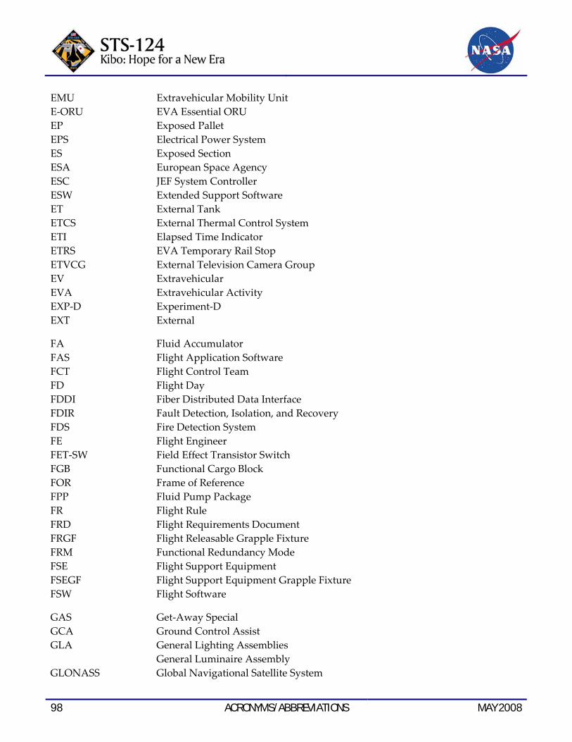
98 ACRONYMS/ABBREVIATIONS MAY 2008
EMU Extravehicular Mobility Unit E‐ORU EVA Essential ORU EP Exposed Pallet EPS Electrical Power System ES Exposed Section ESA European Space Agency ESC JEF System Controller ESW Extended Support Software ET External Tank ETCS External Thermal Control System ETI Elapsed Time Indicator ETRS EVA Temporary Rail Stop ETVCG External Television Camera Group EV Extravehicular EVA Extravehicular Activity EXP‐D Experiment‐D EXT External
FA Fluid Accumulator FAS Flight Application Software FCT Flight Control Team FD Flight Day FDDI Fiber Distributed Data Interface FDIR Fault Detection, Isolation, and Recovery FDS Fire Detection System FE Flight Engineer FET‐SW Field Effect Transistor Switch FGB Functional Cargo Block FOR Frame of Reference FPP Fluid Pump Package FR Flight Rule FRD Flight Requirements Document FRGF Flight Releasable Grapple Fixture FRM Functional Redundancy Mode FSE Flight Support Equipment FSEGF Flight Support Equipment Grapple Fixture FSW Flight Software
GAS Get‐Away Special GCA Ground Control Assist GLA General Lighting Assemblies General Luminaire Assembly GLONASS Global Navigational Satellite System

MAY 2008 ACRONYMS/ABBREVIATIONS 99
GNC GPC GPS GPSR GUI
Guidance, Navigation, and Control General Purpose Computer Global Positioning System Global Positioning System Receiver Graphical User Interface
H&S Health and Status HCE HCTL
Heater Control Equipment Heater Controller
HEPA HPA HPP
High Efficiency Particulate Acquisition High Power Amplifier Hard Point Plates
HRDR HREL HRFM HRM
High Rate Data Recorder Hold/Release Electronics High Rate Frame Multiplexer Hold Release Mechanism
HRMS HTV
High Rate Multiplexer and Switcher H‐II Transfer Vehicle
HTVCC HTV Control Center HTV Prox HX
HTV Proximity Heat Exchanger
I/F IAA IAC
Interface Intravehicular Antenna Assembly Internal Audio Controller
IBM International Business Machines ICB ICC ICS ICS‐EF IDRD IELK IFHX IMCS IMCU IMV
Inner Capture Box Integrated Cargo Carrier Interorbit Communication System Interorbit Communication System ‐ Exposed Facility Increment Definition and Requirements Document Individual Equipment Liner Kit Interface Heat Exchanger Integrated Mission Control System Image Compressor Unit Intermodule Ventilation
INCO Instrumentation and Communication Officer IP International Partner IP‐PCDU ICS‐PM Power Control and Distribution Unit IP‐PDB ISP ISPR
Payload Power Distribution Box International Standard Payload International Standard Payload Rack
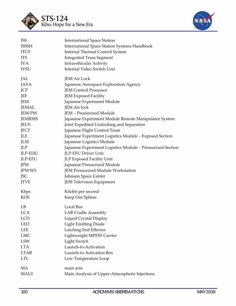
100 ACRONYMS/ABBREVIATIONS MAY 2008
ISS ISSSH ITCS ITS IVA IVSU
International Space Station International Space Station Systems Handbook Internal Thermal Control System Integrated Truss Segment Intravehicular Activity Internal Video Switch Unit
JAL JEM Air Lock JAXA JCP
Japanese Aerospace Exploration Agency JEM Control Processor
JEF JEM JEMAL
JEM Exposed Facility Japanese Experiment Module JEM Air lock
JEM‐PM JEM – Pressurized Module JEMRMS JEUS JFCT JLE JLM JLP JLP‐EDU
Japanese Experiment Module Remote Manipulator System Joint Expedited Undocking and Separation Japanese Flight Control Team Japanese Experiment Logistics Module – Exposed Section Japanese Logistics Module Japanese Experiment Logistics Module – Pressurized Section JLP‐EFU Driver Unit
JLP‐EFU JPM JPM WS
JLP Exposed Facility Unit Japanese Pressurized Module JEM Pressurized Module Workstation
JSC JTVE
Johnson Space Center JEM Television Equipment
Kbps KOS
Kilobit per second Keep Out Sphere
LB Local Bus LCA LCD LED LEE LMC LSW LTA
LAB Cradle Assembly Liquid Crystal Display Light Emitting Diode Latching End Effector Lightweight MPESS Carrier Light Switch Launch‐to‐Activation
LTAB Launch‐to‐Activation Box LTL Low Temperature Loop
MA main arm MAUI Main Analysis of Upper‐Atmospheric Injections

MAY 2008 ACRONYMS/ABBREVIATIONS 101
Mb Megabit Mbps Megabit per second MBS Mobile Base System MBSU Main Bus Switching Unit MCA Major Constituent Analyzer MCC Mission Control Center MCC‐H Mission Control Center – Houston MCC‐M Mission Control Center – Moscow MCDS Multifunction Cathode‐Ray Tube Display System MCS Mission Control System MDA MacDonald, Dettwiler and Associates Ltd. MDM Multiplexer/Demultiplexer MDP Management Data Processor MELFI Minus Eighty‐Degree Laboratory Freezer for ISS MGB Middle Grapple Box MIP Mission Integration Plan MISSE Materials International Space Station Experiment MKAM Minimum Keep Alive Monitor MLE Middeck Locker Equivalent MLI Multi‐layer Insulation MLM Multipurpose Laboratory Module MMOD Micrometeoroid/Orbital Debris MOD Modulator MON Television Monitor MPC Main Processing Controller MPESS Multipurpose Experiment Support Structure MPEV Manual Pressure Equalization Valve MPL Manipulator Retention Latch MPLM Multipurpose Logistics Module MPM Manipulator Positioning Mechanism MPV Manual Procedure Viewer MSD Mass Storage Device MSFC Marshall Space Flight Center MSP Maintenance Switch Panel MSS Mobile Servicing System MT Mobile Tracker MTL Moderate Temperature Loop MUX Data Multiplexer
NASA National Aeronautics and Space Administration NCS Node Control Software NET No Earlier Than
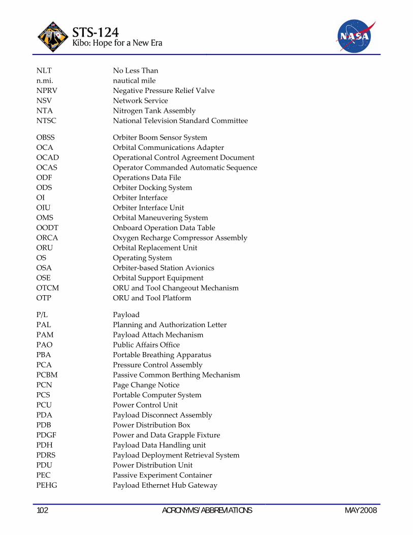
102 ACRONYMS/ABBREVIATIONS MAY 2008
NLT No Less Than n.mi. nautical mile NPRV Negative Pressure Relief Valve NSV Network Service NTA Nitrogen Tank Assembly NTSC National Television Standard Committee
OBSS Orbiter Boom Sensor System OCA Orbital Communications Adapter OCAD Operational Control Agreement Document OCAS Operator Commanded Automatic Sequence ODF Operations Data File ODS Orbiter Docking System OI Orbiter Interface OIU Orbiter Interface Unit OMS Orbital Maneuvering System OODT Onboard Operation Data Table ORCA Oxygen Recharge Compressor Assembly ORU Orbital Replacement Unit OS Operating System OSA Orbiter‐based Station Avionics OSE Orbital Support Equipment OTCM ORU and Tool Changeout Mechanism OTP ORU and Tool Platform
P/L Payload PAL Planning and Authorization Letter PAM Payload Attach Mechanism PAO Public Affairs Office PBA Portable Breathing Apparatus PCA Pressure Control Assembly PCBM Passive Common Berthing Mechanism PCN Page Change Notice PCS Portable Computer System PCU Power Control Unit PDA Payload Disconnect Assembly PDB Power Distribution Box PDGF Power and Data Grapple Fixture PDH Payload Data Handling unit PDRS Payload Deployment Retrieval System PDU Power Distribution Unit PEC Passive Experiment Container PEHG Payload Ethernet Hub Gateway

MAY 2008 ACRONYMS/ABBREVIATIONS 103
PFE PGSC PIB
Portable Fire Extinguisher Payload General Support Computer Power Interface Box
PIU PLB PLBD PLC PLT PM
Payload Interface Unit Payload Bay Payload Bay Door Pressurized Logistics Carrier Payload Laptop Terminal Space Shuttle Pilot Pressurized Module
PMA PMCU POA POR
Pressurized Mating Adapter Power Management Control Unit Payload ORU Accommodation Point of Resolution
PPRV Positive Pressure Relief Valve PRCS PREX
Primary Reaction Control System Procedure Executor
PRLA PROX psia PSP PSRR PTCS PTR
Payload Retention Latch Assembly Proximity Communications Center Pounds per Square Inch Absolute Payload Signal Processor Pressurized Section Resupply Rack Passive Thermal Control System Port Thermal Radiator
PTU PVCU
Pan/Tilt Unit Photovoltaic Controller Unit
PVM Photovoltaic Module PVR Photovoltaic Radiator PVTCS Photovoltaic Thermal Control System
QD Quick Disconnect
R&MA RACU
Restraint and Mobility Aid Russian‐to‐American Converter Unit
RAM RBVM
Read Access Memory Radiator Beam Valve Module
RCC RCT RF RGA RHC
Range Control Center Rack Configuration Table Radio Frequency Rate Gyro Assemblies Rotational Hand Controller
RIGEX Rigidizable Inflatable Get‐Away Special Experiment
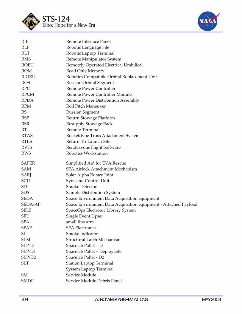
104 ACRONYMS/ABBREVIATIONS MAY 2008
RIP Remote Interface Panel RLF RLT RMS ROEU ROM R‐ORU ROS RPC
Robotic Language File Robotic Laptop Terminal Remote Manipulator System Remotely Operated Electrical Umbilical Read Only Memory Robotics Compatible Orbital Replacement Unit Russian Orbital Segment Remote Power Controller
RPCM Remote Power Controller Module RPDA RPM
Remote Power Distribution Assembly Roll Pitch Maneuver
RS RSP RSR RT
Russian Segment Return Stowage Platform Resupply Stowage Rack Remote Terminal
RTAS RTLS
Rocketdyne Truss Attachment System Return‐To‐Launch‐Site
RVFS RWS
Rendezvous Flight Software Robotics Workstation
SAFER SAM
Simplified Aid for EVA Rescue SFA Airlock Attachment Mechanism
SARJ SCU SD
Solar Alpha Rotary Joint Sync and Control Unit Smoke Detector
SDS SEDA SEDA‐AP SELS SEU SFA
Sample Distribution System Space Environment Data Acquisition equipment Space Environment Data Acquisition equipment ‐ Attached Payload SpaceOps Electronic Library System Single Event Upset small fine arm
SFAE SFA Electronics SI Smoke Indicator SLM Structural Latch Mechanism SLP‐D SLP‐D1 SLP‐D2 SLT SM
Spacelab Pallet – D Spacelab Pallet – Deployable Spacelab Pallet ‐ D2 Station Laptop Terminal System Laptop Terminal Service Module
SMDP Service Module Debris Panel

MAY 2008 ACRONYMS/ABBREVIATIONS 105
SOC System Operation Control SODF Space Operations Data File SPA Small Payload Attachment SPB Survival Power Distribution Box SPDA Secondary Power Distribution Assembly SPDM Special Purpose Dextrous Manipulator SPEC Specialist SRAM Static RAM SRB Solid Rocket Booster SRMS Shuttle Remote Manipulator System SSAS Segment‐to‐Segment Attach System SSC Station Support Computer SSCB Space Station Control Board SSE Small Fine Arm Storage Equipment SSIPC Space Station Integration and Promotion Center SSME Sapce Shuttle Main Engine SSOR Space‐to‐Space Orbiter Radio SSP Standard Switch Panel SSPTS Station‐to‐Shuttle Power Transfer System SSRMS Space Station Remote Manipulator System STC Small Fire Arm Transportation Container STR Starboard Thermal Radiator STS Space Transfer System STVC SFA Television Camera SVS Space Vision System
TA Thruster Assist TAC TCS Assembly Controller TAC‐M TCS Assembly Controller ‐ M TAL Transatlantic Abort Landing TCA Thermal Control System Assembly TCB Total Capture Box TCCS Trace Contaminant Control System TCCV Temperature Control and Check Valve TCS Thermal Control System TCV Temperature Control Valve TDK Transportation Device Kit TDRS Tracking and Data Relay Satellite THA Tool Holder Assembly THC Temperature and Humidity Control Translational Hand Controller THCU Temperature and Humidity Control Unit

106 ACRONYMS/ABBREVIATIONS MAY 2008
TIU Thermal Interface Unit TKSC Tsukuba Space Center (Japan) TLM Telemetry TMA Russian vehicle designation TMR Triple Modular Redundancy TPL Transfer Priority List TRRJ Thermal Radiator Rotary Joint TUS Trailing Umbilical System TV Television TVC Television Camera
UCCAS Unpressurized Cargo Carrier Attach System UCM Umbilical Connect Mechanism UCM‐E UCM – Exposed Section Half UCM‐P UCM – Payload Half UHF Ultrahigh Frequency UIL User Interface Language ULC Unpressurized Logistics Carrier UMA Umbilical Mating Adapter UOP Utility Outlet Panel UPC Up Converter USA United Space Alliance US LAB United States Laboratory USOS United States On‐Orbit Segment
VAJ Vacuum Access Jumper VBSP Video Baseband Signal Processor VCU Video Control Unit VDS Video Distribution System VLU Video Light Unit VRA Vent Relief Assembly VRCS Vernier Reaction Control System VRCV Vent Relief Control Valve VRIV Vent Relief Isolation Valve VSU Video Switcher Unit VSW Video Switcher
WAICO Waiving and Coiling WCL Water Cooling Loop WETA Wireless Video System External Transceiver Assembly WIF Work Interface WRM Water Recovery and Management WRS Water Recovery System
MAY 2008 ACRONYMS/ABBREVIATIONS 107
WS Water Separator Work Site Work Station WVA Water Vent Assembly
ZSR Zero‐g Stowage Rack

108 ACRONYMS/ABBREVIATIONS MAY 2008
This page intentionally left blank.

MAY 2008 MEDIA ASSISTANCE 109
MEDIA ASSISTANCE NASA TELEVISION TRANSMISSION
NASA Television (TV) is carried on an MPEG‐2 digital signal accessed via satellite AMC‐6, at 72 degrees west longitude, transponder 17C, 4040 MHz, vertical polarization. For those in Alaska or Hawaii, NASA TV will be seen on AMC‐7, at 137 degrees west longitude, transponder 18C, at 4060 MHz, horizontal polarization. In both instances, a Digital Video Broadcast (DVB)‐compliant Integrated Receiver Decoder (IRD) (with modulation of QPSK/DBV, data rate of 36.86 and FEC 3/4) will be needed for reception. The NASA TV schedule and links to streaming video are available at:
http://www.nasa.gov/ntv
NASA TV’s digital conversion will require members of the broadcast media to upgrade with an `addressable’ Integrated Receiver De‐coder (IRD), to participate in live news events and interviews, media briefings and receive NASA’s Video File news feeds on a dedicated Media Services channel. NASA mission coverage will air on a digital NASA Public Services (“Free to Air”) channel, for which only a basic IRD will be needed.
Television Schedule
A schedule of key on‐orbit events and media briefings during the mission will be detailed in a NASA TV schedule posted at the link above. The schedule will be updated as necessary and will also be available at:
http://www.nasa.gov/multimedia/nasatv/ mission_schedule.html
Status Reports
Status reports on launch countdown and mission progress, on‐orbit activities and landing operations will be posted at:
http://www.nasa.gov/shuttle
This site also contains information on the crew and will be updated regularly with photos and video clips throughout the flight.
More Internet Information
Information on the ISS is available at:
http://www.nasa.gov/station
Information on safety enhancements made since the Columbia accident is available at:
http://www.nasa.gov/returntoflight/ system/index.html
Information on other current NASA activities is available at:
http://www.nasa.gov
Resources for educators can be found at the following address:
http://education.nasa.gov

110 MEDIA ASSISTANCE MAY 2008
This page intentionally left blank.

MAY 2008 PUBLIC AFFAIRS CONTACTS 111
PUBLIC AFFAIRS CONTACTS HEADQUARTERS WASHINGTON, DC
Michael Braukus Public Affairs Officer International Partners 202‐358‐1979 [email protected]
Katherine Trinidad Public Affairs Officer Space Operations 202‐358‐3749 [email protected]
John Yembrick Public Affairs Officer Space Operations 202‐358‐0602 [email protected]
Mike Curie Public Affairs Officer Space Operations 202‐358‐4715 [email protected]
JOHNSON SPACE CENTER HOUSTON, TEXAS
James Hartsfield News Chief 281‐483‐5111 [email protected]
Kyle Herring Public Affairs Specialist Space Shuttle Program Office 281‐483‐5111 [email protected]
Rob Navias Program and Mission Operations Lead 281‐483‐5111 [email protected]
Kylie Clem Public Affairs Specialist Astronauts and Mission Operations Directorate 281‐483‐5111 [email protected]
Nicole Cloutier‐Lemasters Public Affairs Specialist International Space Station 281‐483‐5111 [email protected]
KENNEDY SPACE CENTER CAPE CANAVERAL, FLORIDA
Allard Beutel News Chief 321‐867‐2468 [email protected]
Candrea Thomas Public Affairs Specialist Space Shuttle 321‐861‐2468 [email protected]
Tracy Young Public Affairs Specialist International Space Station 321‐867‐2468 [email protected]
112 PUBLIC AFFAIRS CONTACTS MAY 2008
MARSHALL SPACE FLIGHT CENTER HUNTSVILLE, ALABAMA
Dom Amatore Public Affairs Manager 256‐544‐0034 [email protected]
June Malone Public Affairs Specialist News Chief/Media Manager 256‐544‐0034 [email protected]
Steve Roy Public Affairs Specialist Space Shuttle Propulsion 256‐544‐0034 [email protected]
STENNIS SPACE CENTER BAY ST. LOUIS, MISSISSIPPI
Linda Theobald Public Affairs Officer 228‐688‐3249 [email protected]
Paul Foerman News Chief 228‐688‐1880 [email protected]
AMES RESEARCH CENTER MOFFETT FIELD, CALIFORNIA
Mike Mewhinney News Chief 650‐604‐3937 [email protected]
Jonas Dino Public Affairs Specialist 650‐604‐5612 [email protected]
DRYDEN FLIGHT RESEARCH CENTER EDWARDS, CALIFORNIA
Fred Johnsen Director, Public Affairs 661‐276‐2998 [email protected]
Alan Brown News Chief 661‐276‐2665 [email protected]
Leslie Williams Public Affairs Specialist 661‐276‐3893 [email protected]
GLENN RESEARCH CENTER CLEVELAND, OHIO
Lori Rachul News Chief 216‐433‐8806 [email protected]
Katherine Martin Public Affairs Specialist 216‐433‐2406 [email protected]
LANGLEY RESEARCH CENTER HAMPTON, VIRGINIA
Marny Skora Head, News Media Office 757‐864‐3315 [email protected]
Chris Rink Public Affairs Officer 757‐864‐6786 [email protected]

MAY 2008 PUBLIC AFFAIRS CONTACTS 113
Kathy Barnstorff Public Affairs Officer 757‐864‐9886 [email protected]
UNITED SPACE ALLIANCE
Jessica Pieczonka Houston Operations 281‐212‐6252 832‐205‐0480 [email protected]
David Waters Florida Operations 321‐861‐3805 [email protected]
BOEING
Tanya Deason‐Sharp Media Relations Boeing Space Exploration 281‐226‐6070 [email protected]
Ed Memi Media Relations Boeing Space Exploration 281‐226‐4029 [email protected]
JAPAN AEROSPACE EXPLORATION AGENCY (JAXA)
JAXA Public Affairs Office Tokyo, Japan 011‐81‐3‐6266‐6414, 6415, 6416, 6417 [email protected]
Kumiko Tanabe JAXA Public Affairs Representative Houston 281‐483‐2251 [email protected]
CANADIAN SPACE AGENCY (CSA)
Jean‐Pierre Arseneault Manager, Media Relations & Information Services Canadian Space Agency 514‐824‐0560 (cell) [email protected]
Isabelle Laplante Media Relations Advisor Canadian Space Agency 450‐926‐4370 [email protected]
EUROPEAN SPACE AGENCY (ESA)
Clare Mattok Communication Dept. Paris, France 011‐33‐1‐5369‐7412 [email protected]

114 PUBLIC AFFAIRS CONTACTS MAY 2008
This page intentionally left blank.