full hd ir network camera - advanced technology video€¦ · full hd ir network camera instruction...
TRANSCRIPT

Please read this manual thoroughly before use, and keep it handy for future reference.
Full HD IR Network Camera
INSTRUCTION MANUAL

ii
WARNING TO REDUCE THE RISK OF FIRE OR ELECTRIC SHOCK, DO NOT EXPOSE THIS PROCUCT TO RAIN OR MOISTURE. DO NOT INSERT ANY METALLIC OBJECT THROUGH THE VENTILATION GRILLS OR OTHER OPENNINGS ON THE EQUIPMENT. Apparatus shall not be exposed to dripping or splashing and that no objects filled with liquids, such as vases, shall be placed on the apparatus. CAUTION
EXPLANATION OF GRAPHICAL SYMBOLS
The lightning flash with arrowhead symbol, within an equilateral triangle, is intended to alert the user to the presence of uninsulated "dangerous voltage" within the product’s enclosure that may be of sufficient magnitude to constitute a risk of electric shock.
The exclamation point within an equilateral triangle is intended to alert the user to the presence of important operating and maintenance (servicing) instructions in the literature accompanying the appliance.

iii
FCC COMPLIANCE STATEMENT
INFORMATION TO THE USER: THIS EQUIPMENT HAS BEEN TESTED AND FOUND TO COMPLY WITH THE LIMITS FOR A CLASS A DIGITAL DEVICE, PURSUANT TO PART 15 OF THE FCC RULES. THESE LIMITS ARE DESIGNED TO PROVIDE REASONABLE PROTECTION AGAINST HARMFUL INTERFERENCE WHEN THE EQUIPMENT IS OPERATED IN A COMMERCIAL ENVIRONMENT. THIS EQUIPMENT GENERATES, USES, AND CAN RADIATE RADIO FREQUENCY ENERGY AND IF NOT INSTALLED AND USED IN ACCORDANCE WITH THE INSTRUCTION MANUAL, MAY CAUSE HARMFUL INTERFERENCE TO RADIO COMMUNICATIONS.
CAUTION: CHANGES OR MODIFICATIONS NOT EXPRESSLY APPROVED BY THE PARTY RESPONSIBLE FOR COMPLIANCE COULD VOID THE USER'S AUTHORITY TO OPERATE THE EQUIPMENT.
THIS CLASS A DIGITAL APPARATUS COMPLIES WITH CANADIAN ICES-003.
CET APPAREIL NUMÉRIQUE DE LA CLASSE A EST CONFORME À LA NORME NMB-003 DU CANADA.
CE COMPLIANCE STATEMENT
WARNING: This is a Class A product. In a domestic environment this product may cause radio interference in which case the user may be required to take adequate measures.
CAUTION RISK OF EXPLOSION IF BATTERY IS REPLACED BY AN INCORRECT TYPE. DISPOSE OF USED BATTERIES ACCORDING TO THE INSTRUCTIONS

iv
IMPORTANT SAFETY INSTRUCTIONS
1. Read these instructions. 2. Keep these instructions. 3. Heed all warnings. 4. Follow all instructions. 5. Do not use this apparatus near water. 6. Clean only with dry cloth. 7. Do not block any ventilation openings. Install in accordance with the manufacturer’s
instructions. 8. Do not install near any heat sources such as radiators, heat registers, stoves, or ot
her apparatus (including amplifiers) that produce heat. 9. Do not defeat the safety purpose of the polarized or grounding-type plug. A polariz
ed plug has two blades with one wider than the other. A grounding type plug has two blades and a third grounding prong. The wide blade or the third prong are provided for your safety. If the provided plug does not fit into your outlet, consult an electrician for replacement of the obsolete outlet.
10. Protect the power cord from being walked on or pinched particularly at plugs, convenience receptacles, and the point where they exit from the apparatus.
11. Only use attachments/accessories specified by the manufacturer. 12. Use only with the cart, stand, tripod, bracket, or table specified
by the manufacturer, or sold with the apparatus. When a cart is used, use caution when moving the cart/apparatus combination to avoid injury from tip-over.
13. Unplug this apparatus during lightning storms or when unused for long periods of time.
14. Refer all servicing to qualified service personnel. Servicing is required when the apparatus has been damaged in any way, such as power-supply cord or plug is damaged, liquid has been spilled or objects have fallen into the apparatus, the apparatus has been exposed to rain or moisture, does not operate normally, or has been dropped.
15. CAUTION – THESE SERVICING INSTRUCTIONS ARE FOR USE BY QUALIFIED SERVICE PERSONNEL ONLY. TO REDUCE THE RISK OF ELECTRIC SHOCK DO NOT PERFORM ANY SERVICING OTHER THAN THAT CONTAINED IN THE OPERATING INSTRUCTIONS UNLESS YOU QRE QUALIFIED TO DO SO.
16. Use satisfy clause 2.5 of IEC60950-1/UL60950-1 or Certified/Listed Class 2 power source only.
17. ITE is to be connected only to PoE networks without routing to the outside plant.

v
Contents
1. Description ............................................................................................................ 1 1.1 Components ................................................................................. 1
1.2 Key Features ................................................................................ 1
2. System Connection .............................................................................................. 2 2.1 Connection ................................................................................... 2
2.2 Network Connection and IP assignment ................................... 5
3. Operation ............................................................................................................... 6 3.1 Download and Install ActiveX ..................................................... 6
3.2 User Login .................................................................................... 7
3.3 Live Video ..................................................................................... 7
3.3.1 Video Control ............................................................................ 8
3.4 Configure ...................................................................................... 9
3.4.1 Quick Setup ............................................................................... 9
3.4.2 Image ....................................................................................... 12
3.4.2.1 ISP Configure ....................................................................... 12
3.4.2.2 Privacy Regional .................................................................. 13
3.4.2.3 OSD ....................................................................................... 13
3.4.2.4 Day/Night Configure ............................................................ 14
3.5.1 Network.................................................................................... 15
3.5.1.1 Network Configure ............................................................... 15
3.5.1.2 PPPoE Configure ................................................................. 16
3.5.1.3 DDNS Configure ................................................................... 16
3.5.1.4 E-mail Configure .................................................................. 17
3.5.1.5 FTP Configure ...................................................................... 18
3.5.1.6 Port Mapping ........................................................................ 18
3.5.2 Alarm ........................................................................................ 19
3.5.2.1 Motion Detection .................................................................. 19
3.5.2.2 I/O .......................................................................................... 20
3.5.3 Audio & Video ......................................................................... 21
3.5.3.1 Stream Configure ................................................................. 21
3.5.3.2 ROI Setting ........................................................................... 22
3.5.4 Storage .................................................................................... 22
3.5.4.1 Record Configure ................................................................ 22

vi
3.5.4.2 Capture Configure ............................................................... 23
3.5.5 Security.................................................................................... 24
3.5.5.1 User Management ................................................................ 24
3.5.5.2 IEEE 802.1xs......................................................................... 24
3.5.5.3 HTTPS Configure ................................................................. 25
3.5.5.4 RTSP Authentication ........................................................... 25
3.5.5 System ..................................................................................... 26
3.5.5.1 Time Parameters .................................................................. 26
3.5.5.2 Device Information .............................................................. 27
3.5.5.3 Maintenance ......................................................................... 27
3.5.5.4 Upgrade Device .................................................................... 28
3.5.5.5 Connection ........................................................................... 29
3.5.6 Local Configure ...................................................................... 29
3.6 Log .............................................................................................. 30
3.7 Logout......................................................................................... 30

1
1. Description The Network Camera supports the network service for an image sensor with progressive scan, which can be monitored on a real-time screen regardless of distances and locations. By using its dedicated program, many users are able to have an access to the Network Camera at once or a single user can monitor various network cameras at the same time. It also enables users to store, retrieve and play an image by using a PC. All the settings and real-time monitoring screens are also provided through an access to the web. The Network Camera is fully featured for security surveillance and remote monitoring needs. It is based on the DSP compression chip, and makes it available on the network as real-time, full frame rate Motion JPEG and H.264 (or MPEG-4) video streams. 1.1 Components The system comes with the following components:
IR Bullet Camera Installation CD Installation Guide Accessory Kit or Turret camera Notes: 1. Check your package to make sure that you received the complete system, including all
components shown above. 2. Adapter for DC 12V is not supplied. 1.2 Key Features Simultaneous H.264, M-JPEG video encoding compression and streaming
Support ISP 2A Technology with (AWB, AE)
Support DWDR, 3D-DNR, Digital Zoom
Support 1280*720@30FPS, 1280*960@30FPS, 1920*1080@30FPS resolution real-time encoding
Support CGI/SDK Development, ONVIF V2.4
IE BROWSER/SAFARI/GOOGLE CHROME/FIREFOX/OPERA, Smart manager, Tive Mobile (Android,
iPhone and iPAD)
Support multi-viewer to access concurrently
Support dual-encoding streams: Main stream, sub stream
Support privacy protection mode, motion detection and sensor alarm functions
Auto-retrieve function and auto-connection network
Network Protocol: TCP/IP, UDP, HTTP, 802.1x, DHCP, DNS, DDNS, RTP, RTSP, PPPoE, SMTP, NTP, SNMP,
FTP, UPNP
Multi-language: Chinese, English, Japanese, Portuguese, Russian, Spanish
2
2. System Connection
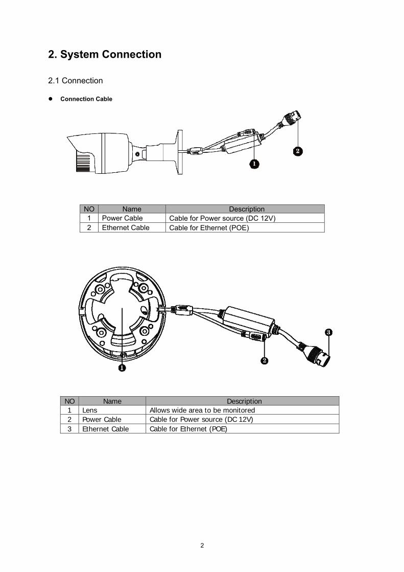
2.1 Connection Connection Cable
NO Name Description 1 Power Cable Cable for Power source (DC 12V) 2 Ethernet Cable Cable for Ethernet (POE)
NO Name Description 1 Lens Allows wide area to be monitored 2 Power Cable Cable for Power source (DC 12V) 3 Ethernet Cable Cable for Ethernet (POE)

3
Camera Dimension
Dimensions Unit: mm
Base Installation Secure the camera to the wall or ceiling by the camera stand (individual purchase). Ceiling Mount Wall Mount
4
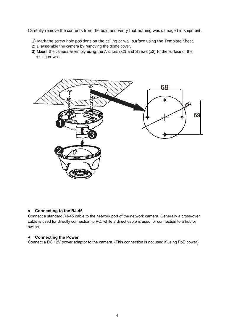
Carefully remove the contents from the box, and verity that nothing was damaged in shipment.
1) Mark the screw hole positions on the ceiling or wall surface using the Template Sheet. 2) Disassemble the camera by removing the dome cover. 3) Mount the camera assembly using the Anchors (x2) and Screws (x2) to the surface of the
ceiling or wall.
Connecting to the RJ-45 Connect a standard RJ-45 cable to the network port of the network camera. Generally a cross-over cable is used for directly connection to PC, while a direct cable is used for connection to a hub or switch. Connecting the Power Connect a DC 12V power adaptor to the camera. (This connection is not used if using PoE power)

5
2.2 Network Connection and IP assignment The Network Camera supports the operation through the network. When a camera is first connected to the network it has no assigned IP address. So, it is necessary to allocate an IP address to the device with the “Smart Manager” utility found in the supplied CD. (Default IP 192.168.30.220) 1. Connect the Network Camera / device to the network and power up. 2. Start SmartManager utility (Start > All programs > SmartManager > SmartManager), the main
window will be displayed, after a short while any network devices connected to the network will be displayed in the list.
3. Select the camera on the list and click right button of the mouse. You can see the pop-up menu
below. 4. Select Assign IP. You will see the "Assign IP Address" window. Enter the required IP address. Note: For more information, refer to the Smart Manger User’s Manual.

6
3. Operation The Network Camera can be used with Windows operating system and browsers. The recommended browsers are Internet Explorer, Safari, Firefox, Opera and Google Chrome with Windows. Note: To view streaming video in Microsoft Internet Explorer, set your browser to allow ActiveX controls. 3.1 Download and Install ActiveX You need to install ActiveX Control when you access IP Camera for the first time through IE browser.
Installation Method:
1) Input the IP address of IP Camera in the browser's address bar (for example: 192.168.1.10) to enter into login
page.
2) Click [Download ActiveX]
3) Pop up a file download dialog box, click [Run] or [Save] to download ActiveX.
4) After the download is complete, double-click the downloaded file “WebClient”, select the installation path, and
click [Install] to install “WebClient”.
5) After the installation is complete, click [Finish] to exit.

7
3.2 User Login Reopen IE web browser after the ActiveX installation completes, input the IP address of IP Camera (192.168.1.10
by default) to enter into login page. Select the system language, input user name and password, then click [Login]
button to enter the main interface.
Note: The default user name is “admin”, the default password is “admin”.
3.3 Live Video After signing in you will see the live video page, or click [Live Video] button in the menu bar to enter this page.
User can do many operations like play, stop, talkback, monitor audio, record, capture, zoom in, show alarm, view
in full-screen mode, control PTZ, adjust video parameters, select stream type and adjust display scale.

8
3.3.1 Video Control [Main / Sub Stream]: Select the stream according to the network environment: main stream is HD channel and
sub stream is SD channel.
[16:9 / 4:3]: Adjust the display scale.
[Play]: Click button to open the current video.
[Stop]: Click button to close the current video.
[Talkback]: Audio talkback switch. Click button to perform the talkback between PC and IP Camera; the
state is changed to after enable audio talkback, click this button to stop talkback.
[Audio]: Open or close the sound of live video.
[Record]: Manual recording switch. Click button to record current video, and save them in AVI format to
“Local recording files path” of local config; the state is changed to after enable recording, click this button to
stop recording.
[Capture]: Click button to generate the screenshot of current views, and save it in JPG format to “Local
capture files path” of local config.
[Digital Zoom]: Click button to enter the E-Zoom mode. The image will be magnified. User can click and
hold your left mouse button to move the image, click to exit the E-Zoom mode.
[Show Alarm]: Click button to pop up alarm information list, it shows the alarm IP, alarm time and alarm
description. Click close button or button to close it.
[Full Screen]: Double-click the video screen to display video in full-screen mode, double-click again or press Esc
key to exit full screen mode.
[Video Parameters]: Click to open PTZ control panel, and adjust the brightness, hue, contrast, saturation
and sharpness of video, click [Default] button to restore the default values.
Note: Note: Support 5 users online at the same time.

9
3.4 Configure
Click [Configure] button in the menu bar to configure parameters.
3.4.1 Quick Setup Step 1: Time Parameters
1) Set up the IP Camera’s date, time and current time zone, or click [Sync PC time] to sync system time with PC.
Enable NTP Service and set its IP and port number, IP Camera will sync system time with NTP server.
2) If you want to use DST function, enable it and set start & end time and shift time.
3) Click [Next] to proceed.
Step 2: Stream Configure

10
1) Set up appropriate stream parameters.
Parameter Description
Stream ID Main stream: HD channel. Sub stream: SD channel.
Stream type Include Only Video and Video & Audio.
Encode type Support the standard H.264 and M-JPEG video encoding.
Frame rate Set the encoding frame numbers per second.
Frame interval The smaller frame interval, the higher image bitrate and the better image quality you get.
Resolution Set the resolution of video.
Video format Set PAL or NTSC.
Bit type CBR: constant encoding bitrate. VBR: variable encoding bitrate.
Stream Size Different stream ID has different bitrate.
2) Click [Back] to change previous settings. Click [Next] to proceed.
Step 3: User Management
1) Add a user: Enter the new user's name and password, set the appropriate user right, and then click [Add].
2) Modify a user: Select a user in the list, modify user information or right, and then click [Modify].
3) Delete a user: Select a user in the list, and then click [Delete].
4) Click [Back] to change previous settings. Click [Next] to proceed.

11
Step 4: Network Parameters
1) Set up the IP Camera’s port number.
2) Set up its IP address, net mask and gateway. Please avoid conflict with the IP addresses of other devices or
PC. If DHCP function of router and IP Camera is enabled, it will automatically obtain IP address from the
router.
3) If you want to use multicast function, set its IP address and port number.
4) Set up the DNS server as your local DNS address for using DDNS function.
5) Click [Back] to change previous settings. Click [Completed] to save the settings.
Note: After modify and save network parameters, IP Camera will restart. All ports (including device port, media port,
web port, ONVIF port, etc) must be forwarded when IPC is accessed via internet.

12
3.4.2 Image 3.4.2.1 ISP Configure
[Brightness / Contrast / Hue / Saturation / Sharpness]: Drag the slider to adjust the brightness, contrast, hue,
saturation and sharpness of video, range from 1 to 255.
[DWDR]: Open this function to balance the contrast between light and dark areas within an image. User can see
highlight areas (under strong light) and low-light areas (shadows, backlighting, etc) simultaneously, otherwise
highlight areas display white and dark areas display black.
[Video Standard]: In indoor environment, if the flashing lamps result in image scintillation, please select 50HZ or
60HZ according to the power frequency.
[Mirror Mode]: Enable or disable mirroring function, set the mirror / flip / mirror and flip mode, video will rotate
horizontally / vertically / both horizontally and vertically.
[AWB Mode]: Select the appropriate mode to adjust the color of screen and make the picture closer to actual
results. There are six modes to choose from.
[3D Noise]: Open or close 3D DNR function.
[Noise Level]: Drag the slider to set the processing level of reducing noise, range from 1 to 255.
[Exposure]: Auto exposure will adjust exposure automatically according to the intensity of light. Manual exposure
can adjust exposure rating manually.
[Indoor And Outdoor]: Select indoor or outdoor mode to get the suitable display result.
Click OK button to save the setting. Click Default button to restore the default setting. When the setting is not saved,
click Refresh button to return to the previously saved parameters; when the setting has been saved, click Refresh
button to query whether the setting is successful.

13
3.4.2.2 Privacy Regional
[Enable]: Enable or disable privacy function.
[Color]: Select the color overlay of privacy area.
Enable privacy function, click and drag cursor to set the privacy area of video image. An image can be entirely or
partially masked, it supports 4 areas at maximum.
Click Clear all button to clear all privacy areas. Click Clear Selected Area button to clear selected privacy area.
Click OK button to save the setting. When the setting is not saved, click Refresh button to return to the previously
saved parameters; when the setting has been saved, click Refresh button to query whether the setting is
successful.
3.4.2.3 OSD
14
Time
[Enable]: Enable this function to display system time.
[Color]: Select different colors for time display. The background color of time area which has a transparency of
30% will automatically adjust according to the character color.
Text
[Enable]: Enable this function to display text content.
[Color]: Select different colors for text display. The background color of text area which has a transparency of 30%
will automatically adjust according to the character color.
[Text]: Click text box to self-define the channel name, it supports 40 English characters or 20 Chinese words at
maximum.
Click and drag system time or text content to adjust the display position.
Click OK button to save the setting. When the setting is not saved, click Refresh button to return to the previously
saved parameters; when the setting has been saved, click Refresh button to query whether the setting is
successful.
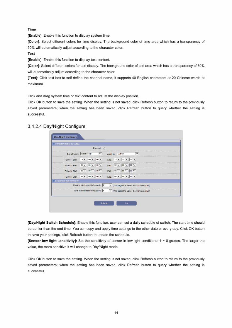
3.4.2.4 Day/Night Configure
[Day/Night Switch Schedule]: Enable this function, user can set a daily schedule of switch. The start time should
be earlier than the end time. You can copy and apply time settings to the other date or every day. Click OK button
to save your settings, click Refresh button to update the schedule.
[Sensor low light sensitivity]: Set the sensitivity of sensor in low-light conditions: 1 ~ 8 grades. The larger the
value, the more sensitive it will change to Day/Night mode.
Click OK button to save the setting. When the setting is not saved, click Refresh button to return to the previously
saved parameters; when the setting has been saved, click Refresh button to query whether the setting is
successful.

15
3.5.1 Network 3.5.1.1 Network Configure
[Device Port]: Default value is 5000 (users are recommended not to change it).
[Media Port]: Default value is 5005.
[Web Port]: Default value is 80 (users are recommended not to change it).
[RTSP Port]: Default value is 554 (users are recommended not to change it).
[ONVIF Port]: Default value is 12001 (users are recommended not to change it).
[DHCP]: If DHCP function of router is enabled, IP Camera will automatically obtain IP address from the router, and
revert to manual IP automatically when DHCP failed.
[IP Address]: Set the IP Camera’s IP address.
[Net mask]: Default value is 255.255.255.0 (users are recommended not to change it).
[Gateway]: Set the IP Camera’s gateway. When the device is connected to public network via a router, gateway
should be set to the router’s IP.
[Multicast Settings]: Multicast means the hosts of a group can receive all the data within this group. Set the IP
address and port number of multicast.
[DNS Server]: User needs to set up the DNS server as your local DNS address for using DDNS function.
Click OK button to save the setting. When the setting is not saved, click Refresh button to return to the previously
saved parameters; when the setting has been saved, click Refresh button to query whether the setting is
successful.
Note: After modify and save network parameters, IP Camera will restart. If the device is applied in LAN, please
avoid conflict with the IP addresses of other devices or PC.

16
3.5.1.2 PPPoE Configure
[Enable]: Enable or disable PPPoE dial-up function.
[Dynamic IP]: Display the public IP Address after the success of dial-up.
[Account/Password]: The account / password of ADSL dial-up, obtained from the internet service provider.
[Dial]: Support PPPoE dialing with wired and wireless.
Click OK button to save the setting. When the setting is not saved, click Refresh button to return to the previously
saved parameters; when the setting has been saved, click Refresh button to query whether the setting is
successful.
3.5.1.3 DDNS Configure
Bind the device with a fixed domain name, so that user can visit the device no matter how the public IP changes.
[Enable]: Enable or disable DDNS function.
[Domain]: Domain name set up by user (e.g. MyIPC.no-ip.org).
[User name/Password]: User name / password registered in DDNS server.
[Domain server]: Select the correct DDNS server.
Click OK button to save the setting. When the setting is not saved, click Refresh button to return to the previously
saved parameters; when the setting has been saved, click Refresh button to query whether the setting is
successful.

17
3.5.1.4 E-mail Configure
[Enable]: Enable or disable E-mail notification function.
[SSL]: Enable or disable mail encryption function.
[SMTP server]: Outgoing Mail Server Address. Mail server addresses are different for different Email service
providers, e.g. the SMTP server of 163.com is smtp.163.com, and the SMTP server of Gmail mailbox is
smtp.gmail.com. Support Gmail and 163.com only.
[Port]: Port number of SMTP server, usually is 25 or 465.
[Sender address]: The E-mail address of sending mail.
[Recipient address]: The E-mail address of receiving mail. Here user can add two E-mail addresses at most.
[Sender name]: Sender’s name.
[User name]: E-mail login user name.
[Password]: E-mail login password.
[Subject]: The subject of sending messages.
Click OK button to save the setting. When the setting is not saved, click Refresh button to return to the previously
saved parameters; when the setting has been saved, click Refresh button to query whether the setting is
successful.

18
3.5.1.5 FTP Configure
When an alarm is triggered, IP Camera will upload text messages and images to FTP server.
[Enable]: Enable or disable FTP function.
[Server address]: FTP server’s IP address or domain name, such as 192.168.1.119.
[Port]: FTP server’s port number, the default value is 21.
[User name/Password]: FTP server’s user name and password.
[FTP Directory]: Set the transmission path on remote FTP server. Click [/Device Name] and [/Channel Name]
button to create a path quickly. It can rename the file, reconnect automatically when time out, and create folders
automatically in the root directory of FTP server.
Click OK button to save the setting. When the setting is not saved, click Refresh button to return to the previously
saved parameters; when the setting has been saved, click Refresh button to query whether the setting is
successful.
3.5.1.6 Port Mapping
Enabling this function can automatically map the port currently in use to router.
If you want to map the port manually, please refer to Appendix 6 for port mapping.

19
3.5.2 Alarm 3.5.2.1 Motion Detection
[Enable]: Enable or disable motion detection function.
[Set Motion Area]: Click and drag cursor to set the area of motion detection in the video window. An image can be
entirely or partially set, it supports 1 area for detection.
[Sensitivity]: Set the sensitivity of motion detection: low, normal, high; the higher grade means higher sensitivity.
[Detection Time Interval]: The time interval between two adjacent detective motions, range from 5 to 10s. If there
is other motion detected during this period, it will be considered continuous movement; otherwise should be
regarded as two different motion events.
[Alarm Schedule]: User can set a daily schedule of motion detection. The start time should be earlier than the
end time. You can copy and apply time settings to the other date or every day. Click OK button to save your
settings, click Refresh button to update the schedule.
[Output]: Linkage alarm output with built-in relay when alarm is triggered.
[Delay]: The duration of linkage alarm output when alarm is triggered, range from 1 to 10s.
[Record]: Linkage recording and store in the SD card when alarm is triggered.
[Linkage Mode]: The duration of linkage recording when alarm is triggered, time range:

20
5/10/30/60/120/300/600/900/1200/1800s.
[Capture]: Linkage capture and store in the SD card when alarm is triggered.
[E-mail]: Enable this function, the alarm information of motion detection will be sent to mailbox (refer to E-mail
Configure). The notification email can contain text messages and images.
[FTP]: Enable this function, the alarm information of motion detection will be saved in FTP Server. It can upload
text messages and images.
Click OK button to save the setting. When the setting is not saved, click Refresh button to return to the previously
saved parameters; when the setting has been saved, click Refresh button to query whether the setting is
successful.
3.5.2.2 I/O
[I/O Type]: Select the I/O alarm type according to alarm trigger type: N.O. (normally open) and N.C. (normally
closed).
[Alarm Schedule]: Enable this function, user can set a daily schedule of I/O detection. The start time should be
earlier than the end time. You can copy and apply time settings to the other date or every day. Click OK button to
save your settings, click Refresh button to update the schedule.
[Output]: Linkage alarm output with built-in relay when alarm is triggered.
[Delay]: The duration of linkage alarm output when alarm is triggered, range from 1 to 10s.
[Record]: Linkage recording and store in the SD card when alarm is triggered.
[Alarm Linkage]: The duration of linkage recording when alarm is triggered, time range:
5/10/30/60/120/300/600/900/1200/1800s.
[Capture]: Linkage capture and store in the SD card when alarm is triggered.
[E-mail]: Enable this function, the information of I/O alarm will be sent to mailbox (refer to E-mail Configure). The
notification email can contain text messages and images.
[FTP]: Enable this function, the information of I/O alarm will be saved in FTP Server. It can upload text messages

21
and images.
Click OK button to save the setting. When the setting is not saved, click Refresh button to return to the previously
saved parameters; when the setting has been saved, click Refresh button to query whether the setting is
successful.
3.5.3 Audio & Video 3.5.3.1 Stream Configure
[Stream ID]: Support two types of streams: main stream is HD channel, and sub stream is SD channel.
[Stream type]: Include Only Video and Video & Audio.
[Encode type]: Support the standard H.264 (under main stream and sub stream) and M-JPEG (under sub stream)
video encoding.
[Frame rate]: Set the encoding frame numbers per second. The adjustable range synchronizes with stream ID.
[Frame interval]: The smaller frame interval, the higher image bitrate and the better image quality you get.
[Resolution]: Set the resolution of video. It can be set as 1080P, 960P, 720P under main stream; and CIF, D1,
VGA under sub stream.
[Video format]: It will appear after selecting sub stream and CIF or D1, set PAL or NTSC.
[Bit type]: CBR adopts constant encoding bitrate, VBR adopts variable encoding bitrate.
[Stream Size]: Different stream ID has different bitrate. Its range is 1000~12000kbps (under main stream) or 64 ~
2048kbps (under sub stream). The higher bitrate can generate better image quality, but it occupies more
bandwidth, please adjust the bitrate value according to your actual bandwidth.
Click OK button to save the setting. When the setting is not saved, click Refresh button to return to the previously
saved parameters; when the setting has been saved, click Refresh button to query whether the setting is
successful.

22
3.5.3.2 ROI Setting Select a region needs to be processed, that is ROI (region of interest). User can set the main concern and the most
interesting region on the video, and IP Camera will improve the corresponding region’s image quality while
encoding.
3.5.4 Storage 3.5.4.1 Record Configure
[Storage rule]:When the storage space is full, “Circle write” will cover the earliest storage files and keep recording,
“Not overwrite” will stop recording and generate alarm automatically.
[Pre-recording]: Alarm signals need a little time to process and trigger recording, it may not record some
important information before alarm activation. This function can save pre-recording (usually is 6~7s) and improve

23
monitoring system reliability, otherwise it only writes the current video data to SD card.
[Stream ID]: The smaller record stream you set, the more video files are stored in SD card. Select a stream type
for recording: main stream is HD channel, and sub stream is SD channel.
[Record Schedule]: Enable this function, user can set a daily schedule of recording. The start time should be
earlier than the end time. You can copy and apply time settings to the other date or every day. Click OK button to
save your settings, click Refresh button to update the schedule.
[FTP upload]: Enable this function to upload the timing record to FTP Server.
Click OK button to save the setting. When the setting is not saved, click Refresh button to return to the previously
saved parameters; when the setting has been saved, click Refresh button to query whether the setting is
successful.
3.5.4.2 Capture Configure
[Setting]: Enable or disable timing capture function; set the time interval of capture, time range: 5/10/15/30/60s. If
the capture interval is set to 5s, IP Camera will capture a picture every 5 seconds in the period of capture schedule,
and store them in the SD card.
[Capture Schedule]: User can set a daily schedule of timing capture. The start time should be earlier than the end
time. You can copy and apply time settings to the other date or every day. Click OK button to save your settings,
click Refresh button to update the schedule.
[FTP upload]: Enable this function to upload the pictures of timing capture to FTP Server.
Click OK button to save the setting. When the setting is not saved, click Refresh button to return to the previously
saved parameters; when the setting has been saved, click Refresh button to query whether the setting is
successful.

24
3.5.5 Security 3.5.5.1 User Management Enter the new user's name and password, set the appropriate user right, then click [Add] button to add this user
into the user list.
Select a user in the user list, modify user information or right, and then click [Modify] button to confirm the changes.
Select a user in the user list, click [Delete] button to delete this user.
Note: 20 users can be added for each IP Camera at most. The admin cannot be modified and deleted.
3.5.5.2 IEEE 802.1xs IP Camera supports IEEE 802.1X. This protocol is used to verify the connected device’s user rights. If the
verification fails, IEEE 802.1X will establish point-to-point connections or prevent access from LAN port. IEEE
802.1X prevents “Port Hijacking” (an unauthorized computer accesses the Internet through the network jack of
inside and outside building). It is very practical for network video application as the network jacks in public space
where IP Cameras are installed often have a potential security liability. In today's enterprise networks, IEEE 802.1X
is becoming the basic requirement of various network connection devices.
IEEE 802.1X, which is based on port, examines objects including requester (such as IP Camera), verifier (such as
switch) and authentication server.

25
Its work processes in the network video system are as follows:
Step 1: IP Camera sends the network access request to switch or AP (Access Point);
Step 2: Switch or AP sends this request to authentication server, such as RADIUS server (Remote
Authentication Dial In User Service) - Microsoft Internet Authentication Service.
Step 3: If the validation is successful, the server informs switch or AP of opening port, and allows IP Camera’s
data to be sent through the switch on the network.
3.5.5.3 HTTPS Configure
HTTPS (Hyper Text Transfer Protocol over Secure Socket Layer) is equivalent to HTTP. The one key difference:
HTTPS transmitted data uses SSL (Secure Sockets Layer) or TLS (Transport Layer Security) encryption. This
security method encrypts the data itself. This product has HTTPS built-in supporting ability in order to guarantee
the web browser to view the video safely. However, using HTTPS will reduce the communication links’ speed and
affect video frame rate.
3.5.5.4 RTSP Authentication
When RTSP request is being sent, IP Camera needs to carry authentication information after enabling the RTSP
authentication function.

26
3.5.5 System 3.5.5.1 Time Parameters
[Time Setting]: Manually set the date and time of IP Camera.
[Sync PC time]: Click this button to sync system time with PC.
[Time zone]: Set the current time zone.
[Daylight Saving Time]: User can enable DST function, and set start & end time and shift time.
[NTP Service]: Enable this function, IP Camera will sync system time with NTP server according to the time zone;
user can also manually set the IP and port number of NTP server.
Click OK button to save the setting. When the setting is not saved, click Refresh button to return to the previously
saved parameters; when the setting has been saved, click Refresh button to query whether the setting is
successful.
27
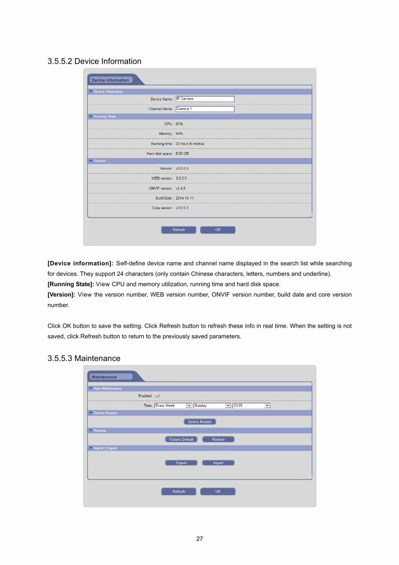
3.5.5.2 Device Information
[Device information]: Self-define device name and channel name displayed in the search list while searching
for devices. They support 24 characters (only contain Chinese characters, letters, numbers and underline).
[Running State]: View CPU and memory utilization, running time and hard disk space.
[Version]: View the version number, WEB version number, ONVIF version number, build date and core version
number.
Click OK button to save the setting. Click Refresh button to refresh these info in real time. When the setting is not
saved, click Refresh button to return to the previously saved parameters.
3.5.5.3 Maintenance
28
[Auto Maintenance]: User can enable the timing reboot function of IP Camera, and set reboot date and time.
[Device Restart]: Click [Device Restart] button to pop up a dialog box, then click OK button to restart IP Camera.
[Restore]: Click [Factory Default] button to pop up a warning window, then click OK button to restore factory
settings and restart the device automatically. Click [Restore] button to pop up a warning window, then click OK
button to restore default values and restart the device automatically.
[Import / Export]: User can export the data files of IP Camera into PC as backup function, or import specified data
files from PC to IP Camera.
Click OK button to save the setting. When the setting is not saved, click Refresh button to return to the previously
saved parameters; when the setting has been saved, click Refresh button to query whether the setting is
successful.
Notice: “Restore factory settings” can restore all user settings and network parameters; “Restore default values”
can restore all user settings and reserve network parameters.
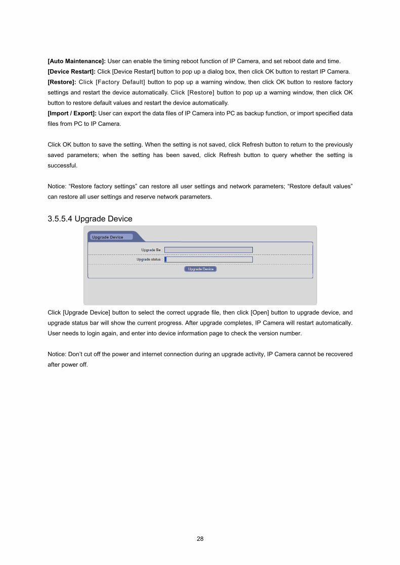
3.5.5.4 Upgrade Device
Click [Upgrade Device] button to select the correct upgrade file, then click [Open] button to upgrade device, and
upgrade status bar will show the current progress. After upgrade completes, IP Camera will restart automatically.
User needs to login again, and enter into device information page to check the version number.
Notice: Don’t cut off the power and internet connection during an upgrade activity, IP Camera cannot be recovered
after power off.

29
3.5.5.5 Connection
In this interface, user can view all user information. Click “Refresh” button to refresh the online user list. User can
preview and configure device remotely through IE web browser, ISS, ISS Mobile and other client. Clicking
“Disconnected” button can take the client offline.
3.5.6 Local Configure
[Protocol]: Support TCP, UDP and multicast network protocol.
[Use Buffer]: In order to avoid the stagnation caused by network congestion during play, using buffer function can
save a certain amount of data before playing. The longer buffer time you set, the longer it takes for video data to
arrive on the client.
[Path]: Click [Browse] button to configure the download path of remote recording files and remote capture files,
configure the storage path of local recording files and local capture files.

30
[Display mode]: Select the video display mode. Two options: full of window and original proportion.
[Length of recording file time]: Select the recording time for each local recording file.
Click OK button to save the setting. When the setting is not saved, click Refresh button to return to the previously
saved parameters; when the setting has been saved, click Refresh button to query whether the setting is
successful.
3.6 Log Click [Log] button in the menu bar to enter the log search page.
[Start Date / End Date]: Select the start date and end date.
[Log Type]: Select the type of log. Five options: all types, system, alarm, operation and network.
After setting the search criteria, click [Refresh] button to search log, the searched log information will be displayed
in the list.
3.7 Logout Click [Logout] button in the menu bar to log out, and return to the login page.

31
Production Specifications Main Item Specification
CAMERA
Image sensor 1/2.7” Progressive scan CMOS Active Array 1920(H) x 1080(V) Lens Fixed 3.6mm Lens, F1.8 Angle of View 90.0°(H) x 50.0(V) IR Distance 20m (with built-in 24 IR LEDs) Min. illumination Color: 0.2Lux, B/W: 0.0Lux (F1.8, 50IRE with IR On) Shutter Speed 1/20,000 ~ 1/30 (Slow shutter 1/15, 1/8 and 1/4) D-WDR, 3D-DNR & D-Zoom Yes
NETWORK
Video Compression -. Motion JPEG -. H.264 (MPEG-4 Part 10)
Video Streaming Simultaneously H.264 and MJPEG Video Resolutions 1920x1080 ~ 320x240 Frame Rate 30fps @ All Resolution
Protocol TCP/IP, UDP, IPv4/v6, HTTP, FTP, uPnP, RTP, RTSP, DHCP, SNMP, PPPoE
Security Multi-user authority, HTTPS, IP Filtering, Privacy Zone(4area)Max. Connection 3
API Programming Interface API Supported, Open Platform Compatible: ONVIF
Alarm Events -. File upload via FTP and HTTP -. Notification via E-mail, HTTP and TCP
Video Buffering Pre and Post Alarm Motion Detection Yes, max. 8 programmable zone Network Time Synchronization Yes Software Reset Yes Factory Reset Yes, Button/Web browser Auto Recovery Yes Installation Tool SmartManager, ATVision IP Upgrade Web browser
GENERAL
Ethernet RJ-45 10BASE-T/100BASE-TX Operating Temperature -20°C ~ 45°C Operation Humidity 0~80% (non-condensing) Housing Weather-proof IP66-rated housing
Power Consumption DC 12V 500mA, 6.0W / PoE 125mA, 6.0W (with IR on) Power over Ethernet IEEE 802.3af Class0
Dimensions (WxHXD) 104mm x 64mm (bullet) / 97.2mm x 80mm (turret) Unit Weight 320g(bullet) / 370g(turret)