full d1 dvr user manual - surveillance- · pdf filefull d1 dvr user manual ... search”...
TRANSCRIPT

700_708h_m769_769-b_769h_798ha_759ha_679ha_706h_796ha_757ha_677ha_677d_792d_792ha_675d_675ha_Manual_V1.7
FULL D1 DVR
User Manual
Intelligent Video Surveillance GUI Display with USB Mouse Control
Please read instructions thoroughly before operation and retain it for future reference.
For the actual display & operation, please refer to your DVR in hand.
IMPORTANT SAFEGUARD
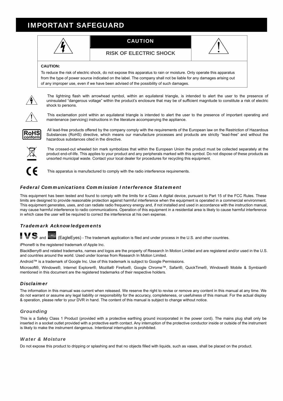
CAUTION
RISK OF ELECTRIC SHOCK
CAUTION:
To reduce the risk of electric shock, do not expose this apparatus to rain or moisture. Only operate this apparatus
from the type of power source indicated on the label. The company shall not be liable for any damages arising out
of any improper use, even if we have been advised of the possibility of such damages.
The lightning flash with arrowhead symbol, within an equilateral triangle, is intended to alert the user to the presence of uninsulated “dangerous voltage” within the product’s enclosure that may be of sufficient magnitude to constitute a risk of electric shock to persons.
This exclamation point within an equilateral triangle is intended to alert the user to the presence of important operating and maintenance (servicing) instructions in the literature accompanying the appliance.
All lead-free products offered by the company comply with the requirements of the European law on the Restriction of Hazardous Substances (RoHS) directive, which means our manufacture processes and products are strictly “lead-free” and without the hazardous substances cited in the directive.
The crossed-out wheeled bin mark symbolizes that within the European Union the product must be collected separately at the product end-of-life. This applies to your product and any peripherals marked with this symbol. Do not dispose of these products as unsorted municipal waste. Contact your local dealer for procedures for recycling this equipment.
This apparatus is manufactured to comply with the radio interference requirements.
Federal Communications Commission Interference Statement
This equipment has been tested and found to comply with the limits for a Class A digital device, pursuant to Part 15 of the FCC Rules. These limits are designed to provide reasonable protection against harmful interference when the equipment is operated in a commercial environment. This equipment generates, uses, and can radiate radio frequency energy and, if not installed and used in accordance with the instruction manual, may cause harmful interference to radio communications. Operation of this equipment in a residential area is likely to cause harmful interference in which case the user will be required to correct the interference at his own expense.
Trademark Acknowledgements
and (EagleEyes) - The trademark application is filed and under process in the U.S. and other countries.
iPhone® is the registered trademark of Apple Inc.
BlackBerry® and related trademarks, names and logos are the property of Research In Motion Limited and are registered and/or used in the U.S. and countries around the world. Used under license from Research In Motion Limited.
Android™ is a trademark of Google Inc. Use of this trademark is subject to Google Permissions.
Microsoft®, Windows®, Internet Explorer®, Mozilla® Firefox®, Google Chrome™, Safari®, QuickTime®, Windows® Mobile & Symbian® mentioned in this document are the registered trademarks of their respective holders.
Disclaimer The information in this manual was current when released. We reserve the right to revise or remove any content in this manual at any time. We do not warrant or assume any legal liability or responsibility for the accuracy, completeness, or usefulness of this manual. For the actual display & operation, please refer to your DVR in hand. The content of this manual is subject to change without notice.
Grounding This is a Safety Class 1 Product (provided with a protective earthing ground incorporated in the power cord). The mains plug shall only be inserted in a socket outlet provided with a protective earth contact. Any interruption of the protective conductor inside or outside of the instrument is likely to make the instrument dangerous. Intentional interruption is prohibited.
Water & Moisture Do not expose this product to dripping or splashing and that no objects filled with liquids, such as vases, shall be placed on the product.

MPEG4 Licensing THIS PRODUCT IS LICENSED UNDER THE MPEG-4 VISUAL PATENT PORTFOLIO LICENSE FOR THE PERSONAL AND NON-COMMERCIAL USE OF A CONSUMER FOR (i) ENCODING VIDEO IN COMPLIANCE WITH THE MPEG-4 VISUAL STANDARD (“MPEG-4 VIDEO”) AND/OR (ii) DECODING MPEG-4 VIDEO THAT WAS ENCODED BY A CONSUMER ENGAGED IN A PERSONAL AND NON-COMMERCIAL ACTIVITY AND/OR WAS OBTAINED FROM A VIDEO PROVIDER LICENSED BY MPEG LA TO PROVIDE MPEG-4 VIDEO. NO LICENSE IS GRANTED OR SHALL BE IMPLIED FOR ANY OTHER USE. ADDITIONAL INFORMATION INCLUDING THAT RELATING TO PROMOTIONAL INTERNAL AND COMMERCIAL USES AND LICENSING MAY BE OBTAINED FROM MPEG LA, LLC. SEE HTTP://WWW.MPEGLA.COM.
GPL Licensing
This product contains codes which are developed by Third-Party-Companies and which are subject to the GNU General Public License (“GPL”) or the GNU Lesser Public License (“LGPL”).
The GPL Code used in this product is released without warranty and is subject to the copyright of the corresponding author.
Further source codes which are subject to the GPL-licenses are available upon request.
We are pleased to provide our modifications to the Linux Kernel, as well as a few new commands, and some tools to get you into the code. The codes are provided on the FTP site, and please download them from the following site or you can refer to your distributor:
http://download.dvrtw.com.tw/GPL/DVR/H-Series/linux.tar.gz

TABLE OF CONTENTS
1. HARDWARE OVERVIEW................................................................................................................ 1
1.1 Package Content ...................................................................................................................................................1
1.2 Front Panel ............................................................................................................................................................1
1.3 Rear Panel .............................................................................................................................................................2
2. CONNECTION AND SETUP ........................................................................................................... 4
2.1 SATA Hard Disk Installation....................................................................................................................................4
2.2 Camera Connection ...............................................................................................................................................7
2.2.1 Normal / DCCS Camera ................................................................................................................................7
2.2.2 PTZ Camera ..................................................................................................................................................7
2.3 External Device Connection...................................................................................................................................8
2.4 DVR Power On ......................................................................................................................................................9
2.5 Date and Time Setting............................................................................................................................................9
2.6 Clear Hard Disk....................................................................................................................................................10
2.7 Password Setting .................................................................................................................................................10
2.8 Examining DCCS Signal Transmission ................................................................................................................11
3. USER INTERFACE........................................................................................................................ 12
3.1 DVR Access .........................................................................................................................................................12
3.2 Live Page .............................................................................................................................................................12
3.1.1 DVR Status ..................................................................................................................................................12
3.1.2 Channel Status. ...........................................................................................................................................13
3.1.3 Record-related Icons ...................................................................................................................................13
3.3 Quick Menu Bar ...................................................................................................................................................13
3.4 Main Menu ...........................................................................................................................................................14
4. FREQUENTLY-USED FUNCTIONS .............................................................................................. 15
4.1 Key Lock / Unlock ................................................................................................................................................15
4.2 User Level Creation .............................................................................................................................................15
4.3 PTZ Control..........................................................................................................................................................16
4.4 Playback ..............................................................................................................................................................17
4.4.1 Playback Control..........................................................................................................................................17
4.4.2 Event Search ...............................................................................................................................................18
4.4.3 Audio Playback ............................................................................................................................................18
4.5 Video Backup.......................................................................................................................................................18
4.6 Video Playback on PC (.dv5) ...............................................................................................................................19
4.6.1 Convert the file format to AVI .......................................................................................................................19
4.7 Digital Zoom.........................................................................................................................................................20
5. MAIN MENU .................................................................................................................................. 21
5.1 QUICK START .....................................................................................................................................................21
5.1.1 GENERAL ...................................................................................................................................................21
5.1.2 TIME SETUP ...............................................................................................................................................22
5.1.3 DAYLIGHT...................................................................................................................................................23
5.2 SYSTEM ..............................................................................................................................................................23
5.2.1 ACCOUNT ...................................................................................................................................................23
5.2.2 TOOLS.........................................................................................................................................................24
5.2.3 SYSTEM INFO ............................................................................................................................................25
5.2.4 BACKUP DATA............................................................................................................................................26
5.2.5 BACKUP LOG .............................................................................................................................................28
5.2.6 REGULAR REPORT ...................................................................................................................................29
5.3 EVENT INFORMATION .......................................................................................................................................29

5.3.1 QUICK SEARCH .........................................................................................................................................29
5.3.2 EVENT SEARCH.........................................................................................................................................30
5.3.3 HDD INFO ...................................................................................................................................................31
5.3.4 EVENT LOG ................................................................................................................................................31
5.4 ADVANCED CONFIG...........................................................................................................................................31
5.4.1 CAMERA .....................................................................................................................................................31
5.4.2 DETECTION................................................................................................................................................32
5.4.3 ALERT .........................................................................................................................................................33
5.4.4 NETWORK ..................................................................................................................................................34
5.4.5 DISPLAY......................................................................................................................................................37
5.4.6 RECORD .....................................................................................................................................................38
5.4.7 DEVICES.....................................................................................................................................................39
5.4.8 DCCS ..........................................................................................................................................................39
5.4.9 IVS...............................................................................................................................................................40
5.4.10 NOTIFY .....................................................................................................................................................44
5.5 SCHEDULE SETTING.........................................................................................................................................47
5.5.1 RECORD .....................................................................................................................................................47
5.5.2 DETECTION................................................................................................................................................48
5.5.3 ALARM ........................................................................................................................................................48
6. REMOTE OPERATION.................................................................................................................. 49
6.1 Supplied Licensed Software.................................................................................................................................49
6.1.1 Installation & Network Connection ...............................................................................................................49
6.1.2 Control Panel Overview ...............................................................................................................................50
6.1.3. General Operation ......................................................................................................................................52
6.1.4. E-Map .........................................................................................................................................................54
6.2 Web Browser .......................................................................................................................................................60
6.2.1 Event Playback & Download........................................................................................................................62
6.2.2 IVS Statistics................................................................................................................................................63
APPENDIX 1 SPECIFICATIONS....................................................................................................... 64
APPENDIX 2 PIN CONFIGURATION................................................................................................ 76
APPENDIX 3 PUSH VIDEO CONFIGURATION ............................................................................... 77
A3.1 PIN Connection .................................................................................................................................................77
A3.2 Configuration .....................................................................................................................................................78
APPENDIX 4 MOBILE SURVEILLANCE VIA EAGLEEYES ............................................................ 80
A4.1 Prerequisites......................................................................................................................................................80
A4.2 Where to download............................................................................................................................................80
APPENDIX 5 SET PUSH VIDEO....................................................................................................... 81
A5.1 Prerequisite .......................................................................................................................................................81
A5.2 Enable Push Video ............................................................................................................................................81
A5.2.1 From iOS® Mobile Device (iPhone® / iPad®)..............................................................................................81
A5.2.2 From Android™ Mobile Device..................................................................................................................82
APPENDIX 6 COMPATIBLE USB FLASH DRIVE LIST ................................................................... 83
APPENDIX 7 COMPATIBLE SATA HDD LIST.................................................................................. 84
APPENDIX 8 MAIN MENU STRUCTURE......................................................................................... 85
APPENDIX 9 DVR BATTERY REPLACEMENT ............................................................................... 87
APPENDIX 10 DVD WRITER INSTALLATION ................................................................................. 88
HARDWARE OVERVIEW
1
1. HARDWARE OVERVIEW
Note: The functions on the front panel and rear panel may vary, depending on the model you have.
1.1 Package Content
Standard Package
DVR HDD screws
Adapter & power cord Manual for IR remote controller
IR remote controller
Optional Accessories
IR Receiver extension cable CD manual
USB Mouse HDD brackets
1.2 Front Panel
1) LED Indicators
DVR is powered on.
The hard disk is reading or recording.
An alarm is triggered.
Timer recording is on.
Under playback status.
2) CH1 ~ 16 / 1 ~ 8 / 1 ~ 4
Press the channel number buttons to select the channel to display.
3)
Press to show the 4 channel display mode.
4) SEQ
Press to display each channel in full screen one by one starting from CH1. When the last channel is displayed, it
will repeat from CH1 again. To exit this mode, press “SEQ” again.
5) SLOW
In the playback mode, press to show slow playback.
6) ZOOM
Press to enlarge the picture of selected channel in the FRAME or FIELD recording mode.
7) PLAY
Press to playback the latest recorded data.
8) LIST (Event List Search)
Press to quickly search the recorded files by event types, or select FULL to show all the event logs.
To quickly search the time you want, select “QUICK SEARCH”. For details, please refer to “5.4.1 QUICK
SEARCH” in the user manual.
9) MENU
Press “MENU” to enter the main menu.
10) ENTER
Press “ENTER” to confirm the setting.

HARDWARE OVERVIEW
2
11) () / () / () / ()
Press / / / to move up / down / left / right.
In the playback mode:
Press “” to pause playback.
Press “” to stop playback.
Press ““ to fast forward.
Press ““ to fast rewind.
12) AUDIO (SLOW + ZOOM)
Press “SLOW” + “ZOOM” to select live or playback audio from audio channel 1~4.
Live audio from audio channel 1~4 (indicated in white).
Playback audio from audio channel 1~4 (indicated in yellow).
Audio channel unselected
13) P.T.Z. ( + SEQ)
Press “ ” + “SEQ” at the same time to enter / exit the PTZ control mode.
14) USB port
There are two USB ports on the front panel, one for connecting your USB mouse for mouse control, and the other
one for connecting your USB flash drive for video backup.
Note: It’s not allowed to have two USB mice or two USB flash drives connected on the front panel.
Note: For the compatible USB flash drive list, please refer to “APPENDIX 6 COMPATIBLE USB FLASH DRIVE LIST” at page 83.
15) (For selected models only)
Press “ ” to eject the disk tray of the DVD writer.
1.3 Rear Panel
1) 75Ω / HI-IMPEDANCE (For selected models only)
When using VIDEO LOOP, switch to HI-IMPEDANCE. If not, switch to 75Ω.
2) VIDEO IN: Connect to the video connector of a camera.
VIDEO LOOP (For selected models only): Video output connector.
Note: The DVR will automatically detect the video system of the camera, please make sure that the cameras are properly connected to the DVR and power-supplied before the DVR is turned on.
3) AUDIO IN (1~4)
Connect to the audio connector of a camera if the camera supports audio recording.
Note: To make a video backup with audio, make sure the camera which supports the audio function is connected to the video-in channel and audio-in channel. For example, the audio data from audio CH1 will be recorded with the video data from video CH1. For 16CH models, the audio CH1 ~ CH4 are corresponding to video CH1 ~ CH4 respectively.
4) AUDIO OUT (1~2)
Connect to a speaker with 1 mono audio output.
5) CALL (For selected models only)
Connect to a monitor specific for sequence display.
6) HDMI
Connect to the HDMI port of the monitor which supports HDMI video output.
Note: Dual video outputs via both VGA and HDMI ports are supported.
HARDWARE OVERVIEW
3
7) VGA
Connect to the VGA port of the monitor which supports VGA video output.
Note: Dual video outputs via both VGA and HDMI ports are supported.
8) IR
Connect the IR receiver extension line for remote control.
9) eSATA (For selected models only)
This port is used to connect a storage device supporting eSATA interface; for instance, an external hard disk or a
disk array.
Note: Please purchase a disk array supporting Linux system to ensure your DVR to work properly.
Note: If the disk array is not connected or detected well, check the mode of your disk array, or do a reset default on your disk array and try again.
10) Push Video Alarm In (For selected models only)
Connect up to four external alarm devices for active event notifications to your smart phone (Push Video). The
four alarm inputs, 1 ~ 4, are corresponding to the four video inputs, CH1 ~ 4.
11) EXTERNAL I/O
This port is used to connect external devices (such as speed dome cameras or external alarm, etc).
12) LAN
Connect to Internet by LAN cable.
13) DC 19V IN
Connect to the supplied adapter.
14) Power Switch (For selected models only)
Switch to “—” to turn on the power, and “” to turn off the power.

CONNECTION AND SETUP
4
2. CONNECTION AND SETUP
Before the DVR is powered on, make sure you have installed a hard disk, connected at least one camera and a
HDMI monitor. For details, please refer to the following sections.
Note: The DVR is designed to automatically detect the video system of the connected cameras (NTSC or PAL). To make sure the system detection is correct, please check if the cameras are connected to the DVR and power-supplied before the DVR is powered on.
2.1 SATA Hard Disk Installation
A SATA hard disk must be installed before the DVR is powered on.
Note: It’s not recommended to use a green hard disk in this device. Please check our hard disk compatible list at page 84.
Note: It’s recommended to clear all data in the hard disk when the DVR is powered on and the date & time are set correctly to ensure the recorded data are not mixed with other data previously saved in the same hard disk. For details, please refer to “2.6 Clear Hard Disk” at page 10.
Type 1
Step1: Loose the screws on the upper cover and open the
upper cover of the DVR.
Note: The DVR cover is made of metal. Please be careful with its edge when you remove the cover.
Step2: There are two hard disk brackets for this DVR as
indicated in the right picture.
Note: The bottom space in “Bracket 2” may be empty for users to install a DVD writer by themselves. To know how to do, please refer to “APPENDIX 10 DVD WRITER INSTALLATION” at page 88.
Front Panel
Bracket 1:Need to be removed first
to fasten a hard disk.
Bracket 2:Fasten a hard disk
directly.
2-1 To install on the first bracket
Remove the bracket, and align the screw holes of the
bracket with the hard disk’s screw holes. Make sure
the PCB side of the hard disk is facing up.
Then, fasten the hard disk to the bracket.
Note: If the second hard disk is to be installed, go to 2-2; If no, go to Step3 directly.
Note: For certain 8CH models, only one hard disk is allowed when a DVD writer is installed.
fasten

CONNECTION AND SETUP
5
2-2 To install on the second bracket
Align the screw holes of the bracket with the hard
disk’s screw holes. Make sure the PCB side of the
hard disk is facing up. Then, fasten the hard disk to
the bracket.
fasten
Step3: Replace the first bracket back to the DVR.
Step4: Connect the power and data bus cables to the hard disk.
Step5: Close the upper cover of the DVR, and fasten all the screws you loosened in Step1.
Type 2
Note: Below takes a 16CH DVR model as an example. This hard disk installation type may also appy to a 8CH or 4CH DVR model.
Step1: Loose the screws on the upper cover and open the upper cover of the DVR.
Note: The DVR cover is made of metal. Please be careful with its edge when you remove the cover.
Step2: Find the HDD brackets supplied in the sales package, and also the screw holes in the DVR as indicated
below.
Note: One hard disk should use two brackets.
Front Panel
Rear Panel
screw hole forhdd bracket

CONNECTION AND SETUP
6
Step3: Attach and fasten the brackets to your hard disk. Make sure the PCB side of the hard disk is facing up.
fasten
Step4: Fasten the hard disk with the brackets to your DVR, as indicated below.
Step5: Connect the power and data bus cables to the hard disk.
Front Panel
Rear Panel
fasten
Step6: Install another hard disk if needed.
Step7: Close the upper cover of the DVR, and fasten all the screws you loosened in Step1.
Type 3
Step1: Loose the screws on the upper cover and open the upper cover of the DVR.
Note: The DVR cover is made of metal. Please be careful with its edge when you remove the cover.
Step2: Place the hard disk to the bracket, and fasten it with the supplied screws. Make sure the PCB side of the
hard disk is facing up.
Front Panel
screw hole
.
Step3: Connect the power and data bus cables to the hard disk.
Front Panel

CONNECTION AND SETUP
7
2.2 Camera Connection
Install the camera on the wall or ceiling based on your installation environment and camera type. For installation
details, please refer to the user manual of your camera.
2.2.1 Normal / DCCS Camera
1) Connecting to DVR video input
Connect the camera video output to the DVR video input port with a coaxial cable or RCA line with a BNC
connector.
Note: For connecting a DCCS-type camera, make sure your DVR model supports DCCS, the camera is connected to the 1st video channel (CH1), and the distance between the camera and DVR needs to be within 200 meters by using a 3C2V coaxial cable (112 braids) for DCCS control to take effects. For more details, please refer to “2.8 Examining DCCS Signal Transmission” at page 11.
2) Connecting to DVR audio input (Optional)
Connect the camera audio output to the DVR audio input port with a coaxial cable or RCA cable with BNC
connectors.
3) Connecting to power
Connect the camera with indicated power supply and make sure it’s power-supplied.
2.2.2 PTZ Camera
The following description is taking our brand’s PTZ camera as an example.
Note: The RS485 wiring is not needed when your DVR and PTZ camera both support DCCS, and the video channel your PTZ camera connects is CH1. If yes, please go to STEP 5 directly for PTZ camera setting.
For detailed PIN / port connection, please refer to “APPENDIX 2 PIN CONFIGURATION” at page 76. For detailed
PTZ camera control and operation, please refer to its own user manual.
RJ11 cable 25 PIN D-Sub Connector
RS485-A: Red wire RS485-A: PIN 12
RS485-B: Green wire RS485-B: PIN 24
1
1516171819202122232425 14
2345678910111213
Solder Side of25-pin D-Sub connector
RS485 -A: PIN12 / RS485-B: PIN2 4
The RJ11 cable is not supplied in the sales package. The D-Sub connector is not supplied with the DVR package.
STEP 1: Get a RJ11 cable with the proper length to your connection.
Different RJ11 connector may have different wire layout, so the connection might be different. If you
cannot control the DVR after connection, please reverse the RJ11 cable connection with the DVR.
STEP 2: Remove one end of the insulating coating of the RJ11 cable.
Remove one end of the insulating coating of the RJ11 cable to find the RS485-A and the RS485-B wires,
and remove the insulating coating to reveal the naked wires for further connection.

CONNECTION AND SETUP
8
STEP 3: Twist the RS485-A and RS485-B wires of the RJ11 cable and the speed dome camera together.
Twist the RS485-A (red) and RS485-B (green) wires of the RJ11 cable to the RS485-A (brown) and
RS485-B (orange) wires of the speed dome camera. To protect the naked wires, use the insulation tape
to cover on the twisted wires.
STEP 4: Connect the other end of the RJ11 cable to DVR.
Solder the RS485-A (red) and RS485-B (green) wires of the RJ11 cable to the corresponding pins on the
solder side of the 9 or 25 PIN D-Sub connector (as shown above).
STEP 5: Set the camera at the DVR side.
Right click to show the main menu in the live view, and go to “ ” (ADVANCED CONFIG) “DEVICES” to set the camera.
a) Select the device to “PTZ”.
b) Set the ID to the value the same as the one set in the camera. The default ID of the camera is 000.
c) Select the protocol to “NORMAL”.
d) Set the baud rate to the value the same as the one set in the camera. The default baud rate of the
camera is 2400.
ADVANCED CONFIG
CAMERA CH1 CH2 CH3 CH4 CH5 CH6 CH7 CH8 CH9 CH10 CH11 DETECTION DEVICE PTZ ALERT ID 000 NETWORK PROTOCOL NORMAL DISPLAY RATE 2400 RECORD DEVICES DCCS IVS NOTIFY
EXIT
2.3 External Device Connection
This device supports external device connection with RS485 and alarm I/O ports, allowing users to connect
control devices such as a PTZ camera or keyboard controller, or connect alarm devices such as a magnetic
contact or buzzer.
Check the user manual of your external device to know which pin(s) should be used, and connect it to the
corresponding pins on the DVR rear panel.
Note: For more details about alarm I/O pin configurations, please refer to “APPENDIX 2 PIN CONFIGURATION” at page 76.
Certain alarm-in pins also support sending instant event notifications to your mobile devices, such as iPhone, iPad
and Android mobile devices, for an alarm event (Push Video). For details, please refer to “APPENDIX 3 PUSH
VIDEO CONFIGURATION” at page 77.

CONNECTION AND SETUP
9
2.4 DVR Power On
This device should be operated only with the type of power source indicated on the manufacturer’s label. Connect
the indicated AC power cord to the power adapter, and plug into an electrical outlet. Then turn the power switch on
the rear panel to “—“. The power LED will be on.
Note: Before the DVR is powered on, make sure (1) the cameras are connected and power-supplied for the detection of the camera video system to be correct, and (2) a HDMI monitor is connected to the DVR for correct video output detection.
Note: To ensure that your DVR works constantly and properly, it's recommended to use an UPS, Uninterruptible Power Supply (Optional), for continuously operation.
2.5 Date and Time Setting
Before operating your DVR, please set the date and time on your DVR FIRST.
Note: Please DO NOT change the date or time of your DVR after the recording function is activated. Otherwise, the recorded data will be disordered and you will not be able to find the recorded file to backup by time search. If users change the date or time accidentally when the recording function is activated, it’s recommended to clear all HDD data, and start recording again.
Note: For the first time to use the DVR, please power it on for at least 48 hours continuously after the date & time is set correctly. It helps to prevent DVR time from resetting after the disconnecting of DVR power. If the DVR time resets after the disconnecting of DVR power, for example, caused by a power outage, the battery might run out and please replace the battery as described in “APPENDIX 9 DVR BATTERY REPLACEMENT” at page 87.
Right-click to enter the DVR password with the password keypad. The default administrator password is admin.
The status will be changed from (key lock) to (unlock). Then, right-click to show the main menu, and
select (QUICK START) “TIME SETUP” to set the date & time.
QUICK START
GENERAL DATE 2009 / NOV / 17 TIME SETUP TIME 15 : 35 : 53 DAYLIGHT
EXIT

CONNECTION AND SETUP
10
2.6 Clear Hard Disk
It’s recommended to clear all data in the hard disk for the first time to user this DVR to ensure the recorded data
are not mixed with other data previously saved in the same hard disk.
Right-click to show the main menu, and select (SYSTEM) “SYSTEM INFO” “CLEAR HDD”. The DVR
will reboot when hard disk data are cleared.
SYSTEM
ACCOUNT BAUD RATE 2400 TOOLS HOST ID 000 SYSTEM INFO R.E.T.R 5 BACKUP DATA AUTO KEY LOCK(S) NEVER BACKUP LOG CLEAR HDD HDD-0 REGULAR REPORT RESET DEFAULT SUBMIT REMOTE CONTROL ID 000 SERIAL TYPE RS485 VIDEO FORMAT NTSC VERSION 1019-1008-1010-1010
EXIT
2.7 Password Setting
Right-click to show the main menu, and select (SYSTEM) “ACCOUNT” to change the default password of
SUPERVISOR.
There are four user levels for different access privileges: SUPERVISOR, POWER USER, NORMAL & GUEST.
For details, please refer to “4.2 User Level Creation” at page 15.
SYSTEM
ACCOUNT USER LIST TOOLS USER NAME LEVEL SYSTEM INFO admin SUPERVISOR BACKUP DATA power POWER USER BACKUP LOG normal NORMAL REGULAR REPORT guest GUEST
EXIT ADD EDIT DEL
CONNECTION AND SETUP
11
2.8 Examining DCCS Signal Transmission
Note: Needed only when the camera connected to CH1 supports DCCS.
Check the channel status bar of CH1, and see if the status icon of DCCS connection is “ ”.
If yes, the connection is ok.
If you see “ ”, make sure:
- The distance between this DVR and the DCCS camera should not exceed 200 meters with a 3C2V coaxial cable (112 braids).
Note: However, different materials used in 3C2V coaxial cables with different connection distance may cause some effects for the availability and fluency of signal transmission.
- It’s not allowed to use a signal booster or modem to amplify signals and extend the connection distance.

USER INTERFACE
12
3. USER INTERFACE
3.1 DVR Access
Connect your USB mouse to one of the USB ports on the DVR front panel, and check if there’s a mouse icon ( ) on the screen, indicating the USB mouse is detected properly.
Move your mouse to enter the DVR password with the password keypad. The default user name and password
are both “admin”. The status will be changed from (key lock) to (unlock).
Note: You may configure four different user levels to have different access privileges in “SYSTEM” “ACCOUNT”. For details, please refer to “4.2 User Level Creation” at page 15.
Password Input
3.2 Live Page
3.1.1 DVR Status
Note: Certain icons are for selected models only.
Key lock Key unlock
Overwrite on Overwrite off
Internet disconnected Internet connected
Local connection USB mouse connected
USB flash drive / device connected No USB device connected
IVS on
Timer record on Timer record off
PTZ mode on PTZ mode off
Sequence mode on Sequence mode off

USER INTERFACE
13
3.1.2 Channel Status
Note: Certain icons are for selected models only.
Original size Fit to screen DCCS connection OK DCCS connection failed
Live audio on Audio off Audio playback on Audio playback off
Recording Human detection event Motion event Alarm event
Record mode: Frame Record mode: Field Record mode: CIF
Virtual fence event One way pass event Scene Change event
3.1.3 Record-related Icons
1) Manual Recording
By defaults, manual recording is on ( ) when the DVR is powered on and a hard disk is installed.
2) Event Recording
The event icons, / / / / / , show on the channel status bar when their respective
events occur and the related record function is on.
3) Timer Recording
When timer recording is on, you will see “ ” on the screen.
4) HDD Overwritten
Be defaults, the HDD overwritten function is set to ON, and “ ” will be shown on the screen.
Note: To disable this function, right click to display the main menu in the live view, and go to “ ” (ADVANCED CONFIG.) “RECORD” “OVERWRITE”.
3.3 Quick Menu Bar
Move to the arrow mark to extend the quick menu bar and show the five functions as follows:
Quick Menu: Open
Click to show the channel switch panel and select the channel you want.
Click to display the playback control panel, and click to play the
latest recorded video clip, or click to enter the search list.
Switch to the channel you want first, and click to enter the zoom-in mode. In this mode, click and drag the red frame on the bottom left of the screen to move to the place you want to see. To exit this mode, click .
Click to show the power off panel to either halt or reboot the system.

USER INTERFACE
14
3.4 Main Menu
Right-click anywhere on the screen to show the main menu as follows, and right-click again to exit.
Main Menu
QUICK START
Click to set the status display, image settings, and date & time.
SYSTEM Click to set the system configurations.
EVENT INFORMATION Click to enter the event search menu.
ADVANCED CONFIG
Click to set CAMERA, DETECTION, ALERT, NETWORK, DISPLAY, RECORD, DEVICES, DCCS*, IVS* & NOTIFY*.
SCHEDULE SETTING
Click to set record timer, detection timer & alarm timer.
* For selected models only

FREQUENTLY-USED FUNCTIONS
15
4. FREQUENTLY-USED FUNCTIONS
4.1 Key Lock / Unlock
To lock or unlock local operation, click (unlock) or (lock) on the DVR status bar to change the status
to (lock) or (unlock).
To unlock local operation, you’ll be prompted to enter the user name and password to access.
Note: The default user name and password are both “admin”, which is the highest user level.
Note: Different user level has different access privilege for certain DVR functions. Please refer to “4.2 User Level Creation” at page 15.
4.2 User Level Creation
Note: This function is available only for “SUPERVISOR”.
To create different user account for different access privilege, click (SYSTEM)), and select “ACCOUNT” to enter “USER LIST”.
SYSTEM
ACCOUNT USER LIST TOOLS USER NAME LEVEL SYSTEM INFO admin SUPERVISOR BACKUP DATA power POWER USER BACKUP LOG normal NORMAL REGULAR REPORT guest GUEST
EXIT ADD EDIT DEL
Different user level has different access privilege for certain functions as described below:
Function User Level
SUPERVISOR POWER NORMAL GUEST
DVR status
/ Key lock / unlock
Channel status
/ Live audio on / off
/ Playback audio on / off
/ Original size / Fit to screen
PTZ Control
Quick menu bar
Channel Selection
Playback
Digital Zoom
Power
FREQUENTLY-USED FUNCTIONS
16
Function User Level
SUPERVISOR POWER NORMAL GUEST
Main menu
Quick Start
System
Event Information
Advanced Config.
Schedule Setting
Playback control
Fast Forward
Fast Rewind
/ Play / Pause
Stop
Slow Playback
/ Previous / Next Hour
Quick Search
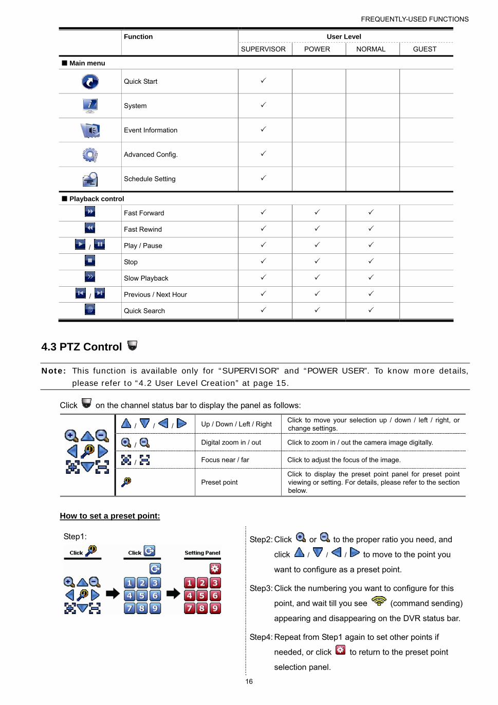
4.3 PTZ Control
Note: This function is available only for “SUPERVISOR” and “POWER USER”. To know more details, please refer to “4.2 User Level Creation” at page 15.
Click on the channel status bar to display the panel as follows:
/ / / Up / Down / Left / Right Click to move your selection up / down / left / right, or change settings.
/ Digital zoom in / out Click to zoom in / out the camera image digitally.
/ Focus near / far Click to adjust the focus of the image.
Preset point Click to display the preset point panel for preset point viewing or setting. For details, please refer to the section below.
How to set a preset point:
Step1:
Step2: Click or to the proper ratio you need, and
click / / / to move to the point you
want to configure as a preset point.
Step3: Click the numbering you want to configure for this
point, and wait till you see (command sending)
appearing and disappearing on the DVR status bar.
Step4: Repeat from Step1 again to set other points if
needed, or click to return to the preset point
selection panel.

FREQUENTLY-USED FUNCTIONS
17
How to go to a preset point:
Step1:
Step2: Select the numbering within which saves the camera view you want to
see, and wait till you see (command sending) appearing and
disappearing on the DVR status bar.
4.4 Playback
Note: This function is NOT available for “GUEST”. please refer to “4.2 User Level Creation” at page 15.
Click “ ” on the quick menu bar to display the playback control panel, and click to play the latest recorded
video clip, or click to enter the search list.
Note: There must be at least 8192 images of recorded data for playback to work properly. If not, the device will stop playback. For example, if the IPS is set to 30, the recording time should be at least 273 seconds (8192 images / 30 IPS) for the playback to work properly.
Note: During playback, the image size of the recording (FRAME , FIELD or CIF ) will be shown on the screen.
4.4.1 Playback Control
Fast Forward Increase the speed for fast forward. Click once to get 4X speed forward and click
twice to get 8X speed, etc., and the maximum speed is 32X.
Fast Rewind Increase the speed for fast rewind. Click once to get 4X speed rewind and click
twice to get 8X speed, etc., and the maximum speed is 32X.
/ Play / Pause
Click to play the latest recorded video clip immediately, and click again to pause.
In the pause mode, click once to get one frame forward, and click to get one frame rewind.
Stop Click to stop the video playback.
Slow Playback Click once to get 1/4X speed playback, and click twice to get 1/8X speed
playback.
/ Previous /
Next Hour
Click to jump to the next / previous time interval in an hour, for example, 11:00 ~
12:00 or 14:00 ~ 15:00, and start playing the earliest event video clip recorded
during this whole hour.
Repeat Click to set point A and point B in a video clip, and the system will play only the
specified range in that clip.
Backup Click to open the backup menu for video backup.
FREQUENTLY-USED FUNCTIONS
18
4.4.2 Event Search
Click to quickly search the recorded files by event types, or select FULL to show all the event logs.
To quickly search the time you want, select “QUICK SEARCH”.
4.4.3 Audio Playback
In the playback mode, click or on the channel status bar to play or mute audio recording.
Note: To make a video backup with audio, or play a recording with audio, make sure the camera which supports the audio function is connected to the video-in channel and audio-in channel. For example, the audio data from audio CH1 will be recorded with the video data from video CH1. For 16CH models, the audio CH1 ~ CH4 are corresponding to video CH1 ~ CH4 respectively.
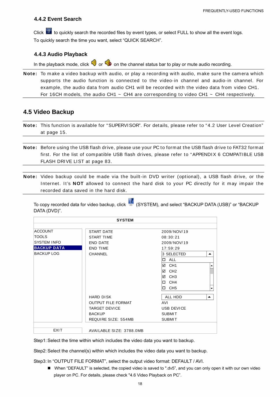
4.5 Video Backup
Note: This function is available for “SUPERVISOR”. For details, please refer to “4.2 User Level Creation” at page 15.
Note: Before using the USB flash drive, please use your PC to format the USB flash drive to FAT32 format first. For the list of compatible USB flash drives, please refer to “APPENDIX 6 COMPATIBLE USB FLASH DRIVE LIST at page 83.
Note: Video backup could be made via the built-in DVD writer (optional), a USB flash drive, or the Internet. It’s NOT allowed to connect the hard disk to your PC directly for it may impair the recorded data saved in the hard disk.
To copy recorded data for video backup, click (SYSTEM), and select “BACKUP DATA (USB)” or “BACKUP DATA (DVD)”.
SYSTEM
ACCOUNT START DATE 2009/NOV/19 TOOLS START TIME 08:30:21 SYSTEM INFO END DATE 2009/NOV/19 BACKUP DATA END TIME 17:59:29 BACKUP LOG CHANNEL 3 SELECTED ALL CH1 CH2 CH3 CH4 CH5 HARD DISK ALL HDD OUTPUT FILE FORMAT AVI TARGET DEVICE USB DEVICE BACKUP SUBMIT REQUIRE SIZE: 554MB SUBMIT
EXIT AVAILABLE SIZE: 3788.0MB
Step1: Select the time within which includes the video data you want to backup.
Step2: Select the channel(s) within which includes the video data you want to backup.
Step3: In “OUTPUT FILE FORMAT”, select the output video format: DEFAULT / AVI.
When “DEFAULT” is selected, the copied video is saved to ".dv5”, and you can only open it with our own video
player on PC. For details, please check "4.6 Video Playback on PC”.
FREQUENTLY-USED FUNCTIONS
19
Note: It’s recommended to save the file to the default format for security reasons. Only specific video player supports the default format and not everyone can see the video footage.
When "AVI" is selected, the copied video will be converted to “avi”, and you can open it with any media player
which supports the “avi” format on PC.
Step4: In “TRAGET DEVICE”, select “USB DEVICE” or “DVD DEVICE” based on the device you want to use for
video backup.
Note: “DVD DEVICE” is available for selected models only.
Step5: In “REQUIRE SIZE”, select “SUBMIT” to know the file size of the selected data.
Step6: In “BACKUP”, select “SUBMIT” to start backup to your USB flash drive, and wait till the backup successful
message appears.
4.6 Video Playback on PC (.dv5)
For video backup with the format “.dv5”, you can only use our own player to play.
Note: It’s NOT allowed to remove the hard disk installed in the DVR and connect it directly to your PC to check recorded video clips. It might impair the files saved in the hark disk, causing the loss of those files even when the disk is replaced back to the DVR.
To play “.dv5” video on your PC:
Step1: Insert the USB flash drive or CD / DVD with recorded data into your PC.
Note: The supported PC operating systems are Windows 7, Vista & XP.
Step2: Find the program “PLAYER.EXE” in the USB flash drive, and double-click it to install.
Note: “PLAYER.EXE” can also be downloaded from www.surveillance-download.com/user/c700.swf.
Step3: Run the program, VideoPlayer, and browse to where you save the recorded data.
Step4: Select the file you want to start video playback
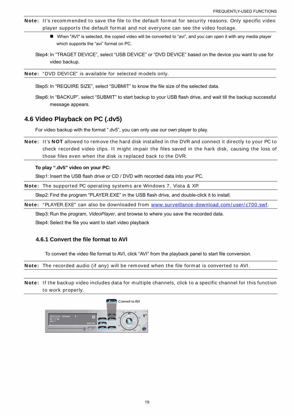
4.6.1 Convert the file format to AVI
To convert the video file format to AVI, click “AVI” from the playback panel to start file conversion.
Note: The recorded audio (if any) will be removed when the file format is converted to AVI.
Note: If the backup video includes data for multiple channels, click to a specific channel for this function to work properly.

FREQUENTLY-USED FUNCTIONS
20
4.7 Digital Zoom
Switch to the channel you want to zoom in, and move to the left side of the screen to show the quick start bar.
Click to enter the zoom-in mode. In this mode, click and drag the red frame on the bottom left of the screen to
move to the place you want to see.
To exit this mode, right-click anywhere on the screen.
Note: You need to exit the zoom mode first to use other DVR functions.
MAIN MENU
21
5. MAIN MENU
5.1 QUICK START
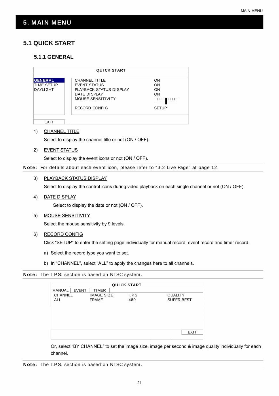
5.1.1 GENERAL
QUICK START
GENERAL CHANNEL TITLE ON TIME SETUP EVENT STATUS ON DAYLIGHT PLAYBACK STATUS DISPLAY ON DATE DISPLAY ON MOUSE SENSITIVITY - ׀ ׀ ׀ ׀ ׀ ׀ ׀ ׀ ׀ + RECORD CONFIG SETUP
EXIT
1) CHANNEL TITLE
Select to display the channel title or not (ON / OFF).
2) EVENT STATUS
Select to display the event icons or not (ON / OFF).
Note: For details about each event icon, please refer to “3.2 Live Page” at page 12.
3) PLAYBACK STATUS DISPLAY
Select to display the control icons during video playback on each single channel or not (ON / OFF).
4) DATE DISPLAY
Select to display the date or not (ON / OFF).
5) MOUSE SENSITIVITY
Select the mouse sensitivity by 9 levels.
6) RECORD CONFIG
Click “SETUP” to enter the setting page individually for manual record, event record and timer record.
a) Select the record type you want to set.
b) In “CHANNEL”, select “ALL” to apply the changes here to all channels.
Note: The I.P.S. section is based on NTSC system.
QUICK START MANUAL EVENT TIMER CHANNEL IMAGE SIZE I.P.S. QUALITY ALL FRAME 480 SUPER BEST
EXIT
Or, select “BY CHANNEL” to set the image size, image per second & image quality individually for each
channel.
Note: The I.P.S. section is based on NTSC system.

MAIN MENU
22
QUICK START MANUAL EVENT TIMER CHANNEL IMAGE SIZE I.P.S. QUALITY CH1 960H 40 SUPER BEST CH2 CIF 30 SUPER BEST CH3 CIF 30 HIGH CH4 FIELD 15 SUPER BEST CH5 FRAME 15 SUPER BEST CH6 CIF 30 SUPER BEST CH7 CIF 30 HIGH CH8 FIELD 7.5 SUPER BEST NEXT AVAILABLE IPS: CIF 705 / FIELD 352.5 / FRAME 176.25
APPLY EXIT
Note: The image size of 960H is available for selected models only.
5.1.2 TIME SETUP
QUICK START
GENERAL DATE 2009 / NOV / 17 TIME SETUP TIME 15 : 35 : 53 DAYLIGHT NTP SERVER tock.stdtime.gov.tw FORMAT Y/M/D SYNC PERIOD DAILY GMT (GMT+08:00)TAIPEI
EXIT
7) DATE
Set the current date. The default display format is YEAR – MONTH – DATE (Y-M-D).
8) TIME
Set the current time in HOUR : MIN : SEC.
9) NTP SERVER
Click to change the default NTP server to another server they’re familiar with, or keep the default NTP
server.
10) FORMAT
Select one date format from the following three options: Y/M/D, M/D/Y or D/M/Y.
11) SYNC PERIOD
Select to synchronize the time everyday (DAILY), or turn this function off (OFF).
12) GMT
Select your time zone.

MAIN MENU
23
5.1.3 DAYLIGHT
QUICK START
GENERAL DAYLIGHT SAVING ON TIME SETUP DAYLIGHT START TIME 1ST MON AUG 06:00 END TIME LAST MON OCT 10:00 ADJUST 01:00
EXIT
Depending on the time zone you’re in:
1) DAYLIGHT SAVING
Select to enable (ON) or disable (OFF) this function.
2) START TIME / END TIME
Set the start time and end time.
3) ADJUST
Set the time in HOUR : MIN.
5.2 SYSTEM
5.2.1 ACCOUNT
This function is used to create a new user account, or modify or delete an existing account for different access
privilege.
Note: For details about available local operations of each user level, please refer to “4.2 User Level Creation” at page 15.
ADVANCED CONFIG
ACCOUNT USER LIST TOOLS USER NAME LEVEL SYSTEM INFO admin SUPERVISOR BACKUP DATA (USB) power POWER USER BACKUP LOG (USB) normal NORMAL REGULAR REPORT guest GUEST EXIT ADD EDIT DEL

MAIN MENU
24
5.2.2 TOOLS
SYSTEM
ACCOUNT LANGUAGE ENGLISH TOOLS UPGRADE SUBMIT SYSTEM INFO NETWORK UPGRADE (For selected models only) SUBMIT BACKUP DATA BACKUP CONFIG SUBMIT BACKUP LOG RESTORE CONFIG SUBMIT REGULAR REPORT
EXIT
1) LANGUAGE
Select the language of the OSD.
2) UPGRADE
Save the upgrade files obtained from your installer or distributor in a compatible USB flash drive, and insert it
into the USB port at the front panel. Then, click “SUBMIT” to start upgrading.
Note: Before using the USB flash drive, please use your PC to format the USB flash drive to FAT32 format first. For the list of compatible USB flash drives, please refer to “APPENDIX 6 COMPATIBLE USB FLASH DRIVE LIST” at page 83.
Note: After upgrading firmware, it’s recommended to clear all HDD data for the system to work more stably. Before clearing all HDD data, please remember to make video backup.
3) NETWORK UPGRADE (For selected models only)
Click “SUBMIT” for perform system upgrade via Internet.
Note: This function requires Internet access. Please make sure your DVR is connected to Internet before using this function.
4) BACKUP CONFIG / RESTORE CONFIG
To keep the current configurations after DVR upgrade, insert a compatible USB flash drive into the USB port,
and select “SUBMIT” in “BACKUP CONFIG” to copy the current DVR configurations to a file “System.bin”
and save to your USB flash drive.
To restore the DVR configurations, insert the USB flash drive including “System.bin” to the USB port, and
select “SUBMIT” in “RESTORE CONFIG”.
MAIN MENU
25
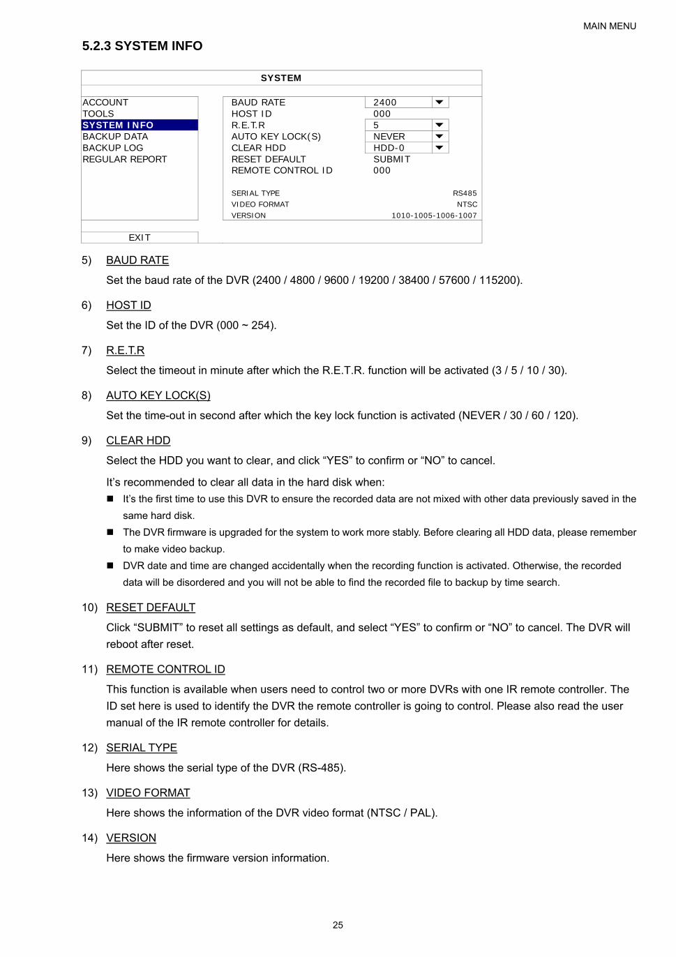
5.2.3 SYSTEM INFO
SYSTEM
ACCOUNT BAUD RATE 2400 TOOLS HOST ID 000 SYSTEM INFO R.E.T.R 5 BACKUP DATA AUTO KEY LOCK(S) NEVER BACKUP LOG CLEAR HDD HDD-0 REGULAR REPORT RESET DEFAULT SUBMIT REMOTE CONTROL ID 000 SERIAL TYPE RS485 VIDEO FORMAT NTSC VERSION 1010-1005-1006-1007
EXIT
5) BAUD RATE
Set the baud rate of the DVR (2400 / 4800 / 9600 / 19200 / 38400 / 57600 / 115200).
6) HOST ID
Set the ID of the DVR (000 ~ 254).
7) R.E.T.R
Select the timeout in minute after which the R.E.T.R. function will be activated (3 / 5 / 10 / 30).
8) AUTO KEY LOCK(S)
Set the time-out in second after which the key lock function is activated (NEVER / 30 / 60 / 120).
9) CLEAR HDD
Select the HDD you want to clear, and click “YES” to confirm or “NO” to cancel.
It’s recommended to clear all data in the hard disk when:
It’s the first time to use this DVR to ensure the recorded data are not mixed with other data previously saved in the
same hard disk.
The DVR firmware is upgraded for the system to work more stably. Before clearing all HDD data, please remember
to make video backup.
DVR date and time are changed accidentally when the recording function is activated. Otherwise, the recorded
data will be disordered and you will not be able to find the recorded file to backup by time search.
10) RESET DEFAULT
Click “SUBMIT” to reset all settings as default, and select “YES” to confirm or “NO” to cancel. The DVR will
reboot after reset.
11) REMOTE CONTROL ID
This function is available when users need to control two or more DVRs with one IR remote controller. The
ID set here is used to identify the DVR the remote controller is going to control. Please also read the user
manual of the IR remote controller for details.
12) SERIAL TYPE
Here shows the serial type of the DVR (RS-485).
13) VIDEO FORMAT
Here shows the information of the DVR video format (NTSC / PAL).
14) VERSION
Here shows the firmware version information.

MAIN MENU
26
5.2.4 BACKUP DATA
Note: It’s NOT allowed to remove the hard disk installed in the DVR and connect it directly to your PC to check recorded video clips. It might impair the files saved in the hard disk, causing the loss of those files even when the disk is replaced back to the DVR.
Note: This function is available only when a hard disk is installed.
Insert a compatible USB flash drive to the USB port at the front panel, or press to eject the DVD writer and
place a DVD-R or CD-R to it.
Note: Copying video footage to CD / DVD is available only for selected models.
Note: Before using the USB flash drive, please use your PC to format the USB flash drive to FAT32 format first. For the list of compatible USB flash drives, please refer to “APPENDIX 6 COMPATIBLE USB FLASH DRIVE LIST” at page 83.
SYSTEM
ACCOUNT START DATE 2009/NOV/19 TOOLS START TIME 08:30:21 SYSTEM INFO END DATE 2009/NOV/19 BACKUP DATA END TIME 17:59:29 BACKUP LOG CHANNEL ALL REGULAR REPORT HARD DISK ALL HDD OUTPUT FILE FORMAT DEFAULT TARGET DEVICE USB DEVICE BACKUP SUBMIT REQUIRE SIZE: 554MB SUBMIT
EXIT AVAILABLE SIZE: 3788.0MB
1) START DATE / START TIME
Select the start date & time.
2) END DATE / TIME
Select the end date & time.
3) CHANNEL
Click to select the channel(s).
4) HARD DISK
Select the hard disk containing the video data you need or “ALL HDD”.
5) OUTPUT FILE FORMAT
Select the file format for backup video: “DEFAULT” or “AVI”.
When “DEFAULT” is selected, the copied video is saved to ".dv5”, and you can only open it with our own video
player on PC. For details, please check the next section, "Video Playback on PC”.
Note: It’s recommended to save the file to the default format for security reasons. Only specific video player supports the default format and not everyone can see the video footage.
When "AVI" is selected, the copied video will be converted to “avi”, and you can open it with any media player
which supports the “avi” format on PC.
6) TARGET DEVICE
Select the device you want to use for video backup: “USB DEVICE” or “DVD DEVICE”.
Note: “DVD DEVICE” is available for selected models only.
MAIN MENU
27
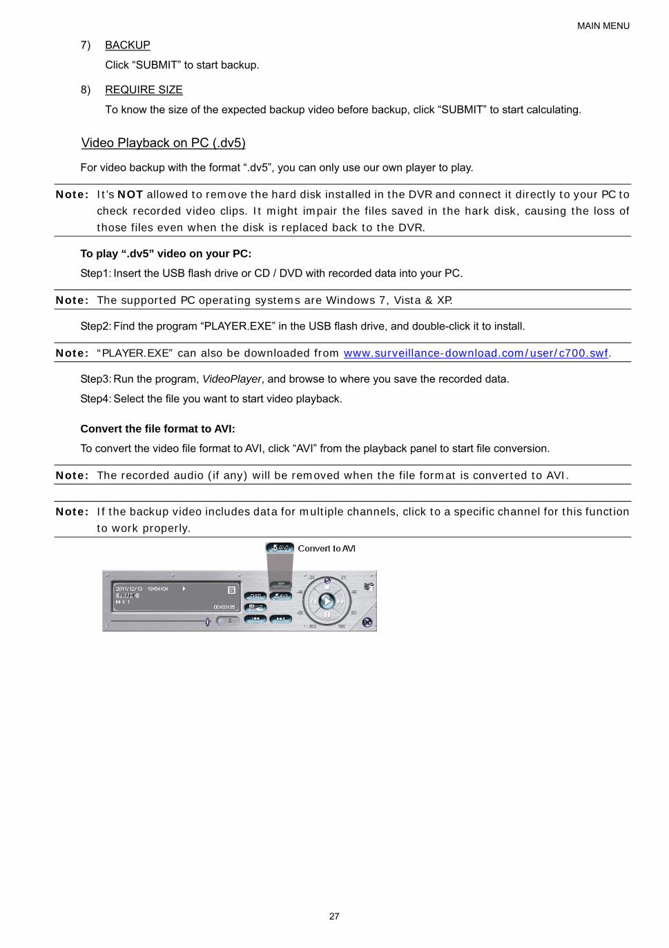
7) BACKUP
Click “SUBMIT” to start backup.
8) REQUIRE SIZE
To know the size of the expected backup video before backup, click “SUBMIT” to start calculating.
Video Playback on PC (.dv5)
For video backup with the format “.dv5”, you can only use our own player to play.
Note: It’s NOT allowed to remove the hard disk installed in the DVR and connect it directly to your PC to check recorded video clips. It might impair the files saved in the hark disk, causing the loss of those files even when the disk is replaced back to the DVR.
To play “.dv5” video on your PC:
Step1: Insert the USB flash drive or CD / DVD with recorded data into your PC.
Note: The supported PC operating systems are Windows 7, Vista & XP.
Step2: Find the program “PLAYER.EXE” in the USB flash drive, and double-click it to install.
Note: “PLAYER.EXE” can also be downloaded from www.surveillance-download.com/user/c700.swf.
Step3: Run the program, VideoPlayer, and browse to where you save the recorded data.
Step4: Select the file you want to start video playback.
Convert the file format to AVI:
To convert the video file format to AVI, click “AVI” from the playback panel to start file conversion.
Note: The recorded audio (if any) will be removed when the file format is converted to AVI.
Note: If the backup video includes data for multiple channels, click to a specific channel for this function to work properly.
MAIN MENU
28
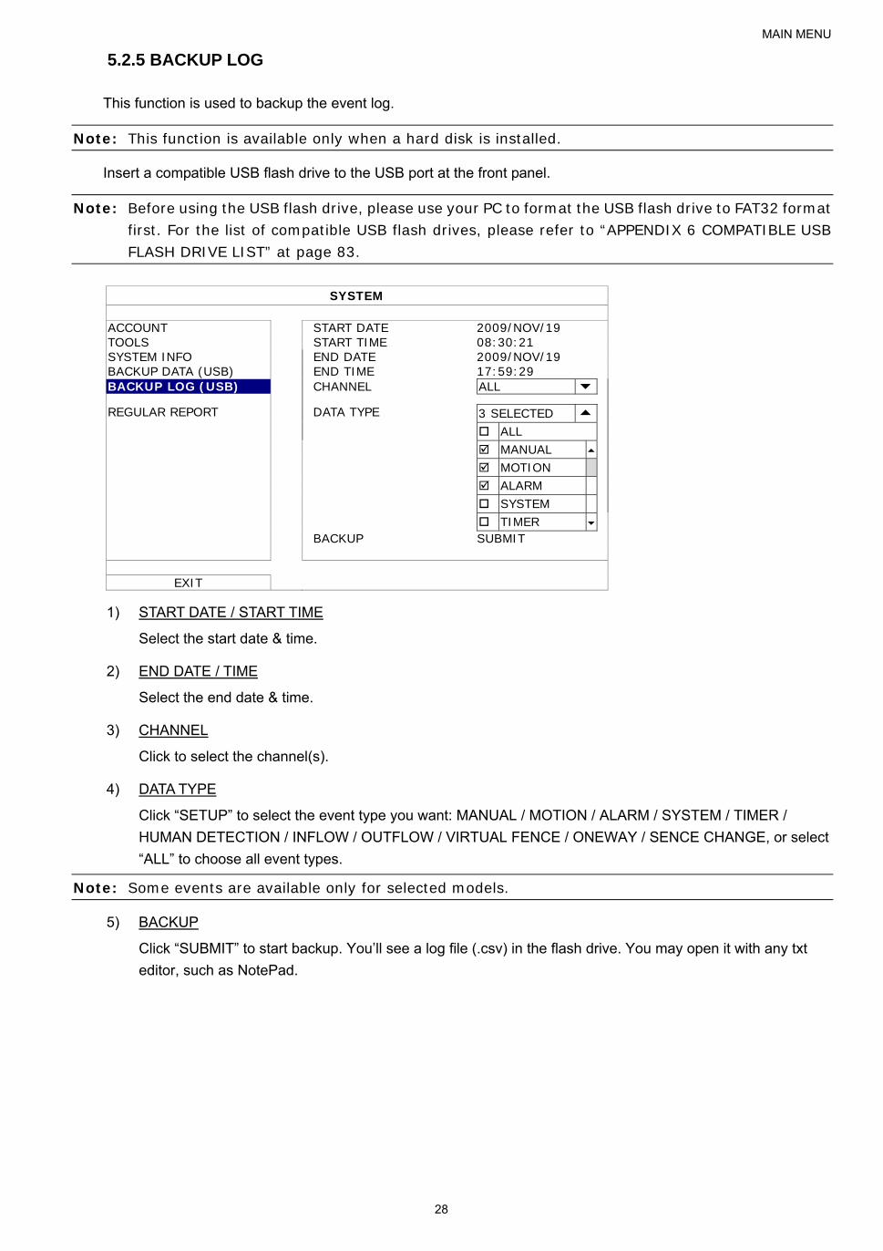
5.2.5 BACKUP LOG
This function is used to backup the event log.
Note: This function is available only when a hard disk is installed.
Insert a compatible USB flash drive to the USB port at the front panel.
Note: Before using the USB flash drive, please use your PC to format the USB flash drive to FAT32 format first. For the list of compatible USB flash drives, please refer to “APPENDIX 6 COMPATIBLE USB FLASH DRIVE LIST” at page 83.
SYSTEM
ACCOUNT START DATE 2009/NOV/19 TOOLS START TIME 08:30:21 SYSTEM INFO END DATE 2009/NOV/19 BACKUP DATA (USB) END TIME 17:59:29 BACKUP LOG (USB) CHANNEL ALL REGULAR REPORT DATA TYPE 3 SELECTED ALL MANUAL MOTION ALARM SYSTEM TIMER BACKUP SUBMIT
EXIT
1) START DATE / START TIME
Select the start date & time.
2) END DATE / TIME
Select the end date & time.
3) CHANNEL
Click to select the channel(s).
4) DATA TYPE
Click “SETUP” to select the event type you want: MANUAL / MOTION / ALARM / SYSTEM / TIMER /
HUMAN DETECTION / INFLOW / OUTFLOW / VIRTUAL FENCE / ONEWAY / SENCE CHANGE, or select
“ALL” to choose all event types.
Note: Some events are available only for selected models.
5) BACKUP
Click “SUBMIT” to start backup. You’ll see a log file (.csv) in the flash drive. You may open it with any txt
editor, such as NotePad.

MAIN MENU
29
5.2.6 REGULAR REPORT
This function is used to send event reports to the specified E-mail address. Users could configure up to 5 profiles
to receive different reports about specific channels at different time.
Note: This function is available only when a hard disk is installed.
SYSTEM
ACCOUNT PROFILE 1 TOOLS ACTIVE ON SYSTEM INFO PERIOD DAILY BACKUP DATA DAY OF MONTH 1 BACKUP LOG HOUR 1 REGULAR REPORT CHANNEL CH1 EVENT TYPE MOTION E-MAIL SETUP
EXIT
Step1: Select the profile you want to configure, and enable it.
Step2: Select the frequency to send reports in “PERIOD”: DAILY / MONTH / WEEK.
Step3: When MONTH or WEEK is selected, select which date or day from “DAY OF MONTH” or “DAY OF WEEK”.
Step4: Then, select which time you want to receive reports, which channel(s) you want to see, and which event
type(s) you want to see (ALARM / MANUAL / MOTION / SYSTEM / TIMER / INFLOW / OUTFLOW /
VIRTUAL FENCE / ONEWAY / SCENE CHANGE / HUMAN DETECTION).
Note: Some event types are available only for selected models.
Step5: Configure the email address to receive reports.
Note: The sender E-mail should be configured in “ADVANCED CONFIG” “NETWORK” “E-MAIL” for this function to work properly. For details, please refer to “E-MAIL” at page 36.
5.3 EVENT INFORMATION
5.3.1 QUICK SEARCH
EVENT INFORMATION QUICK SEARCH HARD DISK ALL HDD
EVENT SEARCH CHANNEL 2 SELECTED HDD INFO EVENT LOG 2009 NOV SUN MON TUE WED THU FRI SAT 1 2 3 4 5 6 7 8 9 10 11 12 13 14 15 16 17 18 19 20 21
22 23 24 25 26 27 28 29 30 00 06 12 18 24
EXIT 15 : 20 SUBMIT
Step1: Select the hard disk and channel including the video data you want to search.

MAIN MENU
30
Step2: Select the year and month including the video data you want to search from the calendar, and the date with
recorded data will be highlighted.
Note: To select the year and month, move your mouse to the display bar. Then, click and hold to drag up or down.
Step3: Select the date you want from the calendar, and the time with recorded data will be highlighted from the
time scale bar.
Step4: To immediately play the video clip, click “SUBMIT”.
To choose the start time for video playback, move your mouse cursor to the highlighted time, and click to
confirm the time when the time display below is the time you want. The video playback is activated right
away when you confirm the time.
Note: For video playback operations, please refer to “4.4 Playback” at page 17.
5.3.2 EVENT SEARCH
EVENT INFORMATION
QUICK SEARCH DATE 2009/NOV/19 EVENT SEARCH TIME 16:13:16 HDD INFO CHANNEL 1
EVENT LOG HARD DISK ALL HDD
EVENT TYPE MOTION SEARCH START
EXIT
1) DATE / TIME
Select the specific time period that you want to search.
2) CHANNEL
Select the video channel you want to search.
3) HARD DISK
Select the hard disk including the video data you want to search, or select “ALL HDD”.
4) EVENT TYPE
Select the event type you want to search, or select “ALL” to choose all events.
Note: Some events are available only for selected models.
5) SEARCH
Click “START” to start search and play the video data immediately.
MAIN MENU
31
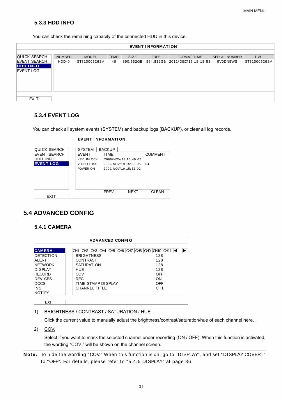
5.3.3 HDD INFO
You can check the remaining capacity of the connected HDD in this device.
EVENT INFORMATION
QUICK SEARCH NUMBER MODEL TEMP. SIZE FREE FORMAT TIME SERIAL NUMBER F.W. EVENT SEARCH HDD-0 ST31000526SV 46 890.562GB 864.832GB 2011/DEC/13 18:18:53 9V0DN5WS ST31000526SV HDD INFO EVENT LOG
EXIT
5.3.4 EVENT LOG
You can check all system events (SYSTEM) and backup logs (BACKUP), or clear all log records.
EVENT INFORMATION
QUICK SEARCH SYSTEM BACKUP EVENT SEARCH EVENT TIME COMMENT HDD INFO KEY UNLOCK 2009/NOV/19 15:49:07 EVENT LOG VIDEO LOSS 2009/NOV/19 15:32:05 04 POWER ON 2009/NOV/19 15:32:02
PREV NEXT CLEAN EXIT
5.4 ADVANCED CONFIG
5.4.1 CAMERA
ADVANCED CONFIG
CAMERA CH1 CH2 CH3 CH4 CH5 CH6 CH7 CH8 CH9 CH10 CH11 DETECTION BRIGHTNESS 128 ALERT CONTRAST 128 NETWORK SATURATION 128 DISPLAY HUE 128 RECORD COV. OFF DEVICES REC ON DCCS TIME STAMP DISPLAY OFF IVS CHANNEL TITLE CH1 NOTIFY
EXIT
1) BRIGHTNESS / CONTRAST / SATURATION / HUE
Click the current value to manually adjust the brightness/contrast/saturation/hue of each channel here. .
2) COV.
Select if you want to mask the selected channel under recording (ON / OFF). When this function is activated,
the wording “COV.” will be shown on the channel screen.
Note: To hide the wording “COV.” When this function is on, go to “DISPLAY”, and set “DISPLAY COVERT” to “OFF”. For details, please refer to “5.4.5 DISPLAY” at page 36.
MAIN MENU
32
3) REC
Select if you want to enable recording for the selected channel (ON / OFF).
Note: When this function is disabled, no manual, event or timer recording will be activated even if any of these three record functions is set to “ON”.
4) TIME STAMP DISPLAY
Enable this function and the recording time will be shown on the video during video playback.
5) CHANNEL TITLE
Click the channel title column to change the channel title (up to 12 characters). The default title is the
channel number.
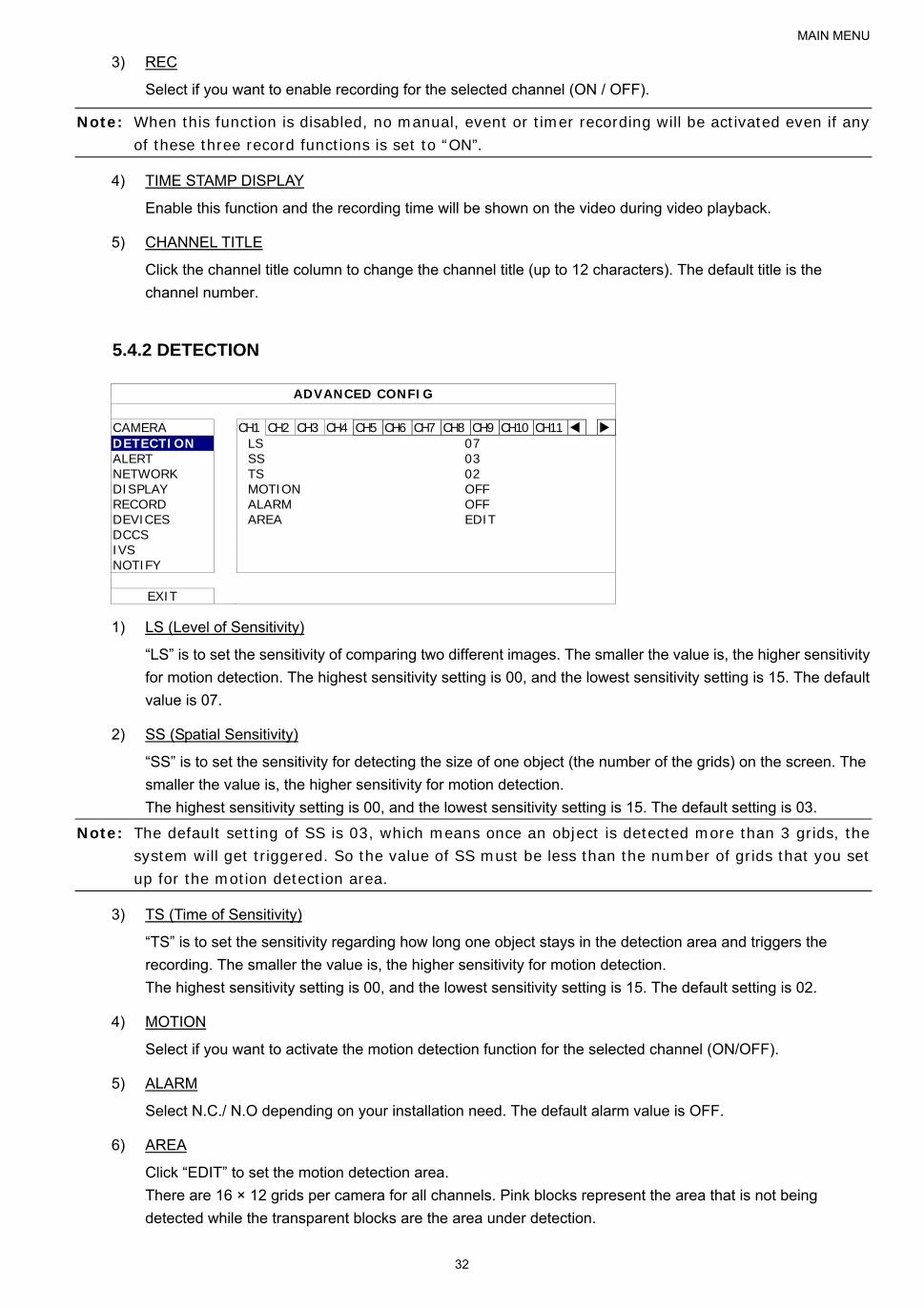
5.4.2 DETECTION
ADVANCED CONFIG
CAMERA CH1 CH2 CH3 CH4 CH5 CH6 CH7 CH8 CH9 CH10 CH11 DETECTION LS 07 ALERT SS 03 NETWORK TS 02 DISPLAY MOTION OFF RECORD ALARM OFF DEVICES AREA EDIT DCCS IVS NOTIFY
EXIT
1) LS (Level of Sensitivity)
“LS” is to set the sensitivity of comparing two different images. The smaller the value is, the higher sensitivity
for motion detection. The highest sensitivity setting is 00, and the lowest sensitivity setting is 15. The default
value is 07.
2) SS (Spatial Sensitivity)
“SS” is to set the sensitivity for detecting the size of one object (the number of the grids) on the screen. The
smaller the value is, the higher sensitivity for motion detection.
The highest sensitivity setting is 00, and the lowest sensitivity setting is 15. The default setting is 03.
Note: The default setting of SS is 03, which means once an object is detected more than 3 grids, the system will get triggered. So the value of SS must be less than the number of grids that you set up for the motion detection area.
3) TS (Time of Sensitivity)
“TS” is to set the sensitivity regarding how long one object stays in the detection area and triggers the
recording. The smaller the value is, the higher sensitivity for motion detection.
The highest sensitivity setting is 00, and the lowest sensitivity setting is 15. The default setting is 02.
4) MOTION
Select if you want to activate the motion detection function for the selected channel (ON/OFF).
5) ALARM
Select N.C./ N.O depending on your installation need. The default alarm value is OFF.
6) AREA
Click “EDIT” to set the motion detection area.
There are 16 × 12 grids per camera for all channels. Pink blocks represent the area that is not being
detected while the transparent blocks are the area under detection.

MAIN MENU
33
5.4.3 ALERT
ADVANCED CONFIG
CAMERA EXT. ALERT ON DETECTION INT. BUZZER OFF ALERT KEY BUZZER ON NETWORK VLOSS BUZZER ON DISPLAY MOTION BUZZER ON RECORD ALARM BUZZER ON DEVICES HDD BUZZER ON DCCS ALARM DURATION (SEC) 5 IVS HDD NEARLY FULL (GB) 5 NOTIFY HDD OVERHEAT ALERT (°C) 60
EXIT
1) EXT. ALERT
Select to enable or disable the sound when any external alarm is triggered (ON / OFF).
2) INT. BUZZER
Select to enable or disable the sound (ON / OFF) for all internal buzzers: KEY BUZZER, VLOSS BUZZER,
MOTION BUZZER, ALARM BUZZER, and HDD BUZZER.
Note: When this item is set to “OFF”, item 3) to item 7) will be disabled even though they are set to ON.
3) KEY BUZZER
Select to enable or disable the sound when pressing the buttons on the front panel (ON / OFF).
4) VLOSS BUZZERD
Select to enable or disable the sound when video loss happened (ON / OFF).
5) MOTION BUZZER
Select to enable or disable the sound when any motion alarm is triggered (ON / OFF).
6) ALARM BUZZER
Select to enable or disable the sound when any internal alarm is triggered (ON / OFF).
7) HDD BUZZER
Select to enable or disable the sound (ON / OFF) when the HDD remaining capacity reaches to the value set
in “HDD NEARLY FULL (GB)”.
8) ALARM DURATION (SEC)
Select the duration time for alarm buzzer in second (5 / 10 / 20 / 40).
9) HDD NEARLY FULL (GB)
If HDD BUZZER is enabled, select the duration time for buzzer notifications when the hard disk available
capacity is 5/10/15/20 GB left.
10) HDD OVERHEAT ALERT (°C)
Select the temperature alert for your hard disk to be aware of the possible overheat of your hard disk.

MAIN MENU
34
5.4.4 NETWORK
NETWORK
SSTTAATTIICC
ADVANCED CONFIG
CAMERA WAN FTP E-MAIL DDNS DETECTION NETWORK TYPE STATIC ALERT IP 192.168.001.010 NETWORK GATEWAY 192.168.001.254 DISPLAY NETMASK 255.255.255.000 RECORD PRIMARY DNS 168.095.001.001 DEVICES SECONDARY DNS 139.175.055.244 DCCS PORT 0080 IVS APPLY NOTIFY
EXIT MAC: 00:0E:53:EC:A7:B4
1) NETWORK TYPE
Select the network type as STATIC and set all the information needed in the DVR.
2) NETWORK INFORMATION (IP / GATEWAY / NETMASK)
Key in all the network information obtained from your ISP (Internet Service Provider).
3) DNS (PRIMARY DNS / SECONDARY DNS)
Key in the IP address of the domain name server obtained from your ISP (Internet Service
Provider).
4) PORT
The valid number ranges from 1 to 9999. The default value is 80. Typically, the TCP port used by
HTTP is 80. However in some cases, it is better to change this port number for added flexibility or
security.
PPPPPPOOEE
Note: When PPPOE configuration is completed, please move to “DDNS” to configure the DDNS service.
ADVANCED CONFIG
CAMERA WAN FTP E-MAIL DDNS DETECTION NETWORK TYPE PPPOE ALERT IP 192.168.001.010 NETWORK GATEWAY 192.168.001.254 DISPLAY NETMASK 255.255.255.000 RECORD PRIMARY DNS 168.095.001.001 DEVICES SECONDARY DNS 139.175.055.244 DCCS PORT 0080 IVS USER NAME OFFICE NOTIFY PASSWORD
EXIT MAC: 00:0E:53:EC:A7:B4
1) NETWORK TYPE
Select the network type as PPPOE and set all the information needed in the DVR.
2) DNS (PRIMARY DNS / SECONDARY DNS)
Key in the IP address of the domain name server obtained from your ISP (Internet Service
Provider).

MAIN MENU
35
3) PORT
The valid number ranges from 1 to 9999. The default value is 80. Typically, the TCP port used by
HTTP is 80. However in some cases, it is better to change this port number for added flexibility or
security.
4) USER NAME / PASSWORD
Set “username” and “password” subscribed from your ISP supplier
DDHHCCPP
Note: When DHCP configuration is completed, please move to “DDNS” to configure the DDNS service.
ADVANCED CONFIG
CAMERA WAN FTP E-MAIL DDNS DETECTION NETWORK TYPE DHCP ALERT IP 192.168.001.010 NETWORK GATEWAY 192.168.001.254 DISPLAY NETMASK 255.255.255.000 RECORD PRIMARY DNS 168.095.001.001 DEVICES SECONDARY DNS 139.175.055.244 DCCS PORT 0080 IVS NOTIFY
EXIT MAC: 00:0E:53:EC:A7:B4
1) NETWORK TYPE
Select the network type as DHCP.
2) DNS (PRIMARY DNS / SECONDARY DNS)
Key in the IP address of the domain name server obtained from your ISP (Internet Service
Provider).
3) PORT
The valid number ranges from 1 to 9999. The default value is 80. Typically, the TCP port used by
HTTP is 80. However in some cases, it is better to change this port number for added flexibility or
security.
FTP
When this function is enabled and an event occurs, a html file including a link will be sent to the specified FTP site.
Click the link to access to this DVR and check the event recording.
ADVANCED CONFIG
CAMERA WAN FTP E-MAIL DDNS DETECTION FTP ALERT ON ALERT USER NAME MANAGER NETWORK PASSWORD DISPLAY SERVER 192.168.2.32 RECORD PORT 0021 DEVICES DIRECTORY UPLOAD DCCS IVS NOTIFY
EXIT

MAIN MENU
36
When this function is enabled and an event occurs, a html file including a link will be sent to the specified E-mail
address. Click the link to access to this DVR and check the event recording.
ADVANCED CONFIG
CAMERA WAN FTP E-MAIL DDNS DETECTION E-MAIL ALERT ON ALERT SMTP SERVER SMTP.GMAIL.COM NETWORK PORT 465 DISPLAY MAIL FROM MANAGER RECORD SSL ENCRYPTION ON DEVICES VERIFY PASSWORD ON DCCS USER NAME MANAGER IVS PASSWORD NOTIFY RECEIVER SETUP
EXIT
1) E-MAIL ALERT
Select “ON” to enable this function, or “OFF” to disable this function.
2) SMTP SERVER
Enter the SMTP server address provided from your e-mail system supplier.
3) PORT
Enter the port number provided from your e-mail system supplier. If this column is left blank, the e-mail
server will use port 25 to send e-mails.
4) MAIL FROM
Enter the sender’s name.
5) SSL ENCRYPTION
Select “ON” if your e-mail server is using SSL encryption to protect your e-mail content from unauthorized
access.
6) VERIFY PASSWORD
Some mail servers are required to verify the password. Please enter the “user name” and “password”.
7) USER NAME / PASSWORD
Enter the “user name” and “password” when “VERIFY PASSWORD” is set to “ON”.
8) RECEIVER
Select “SETUP” to add up to 15 e-mail addresses of the assigned recipients.
DDNS
You need to additionally set DDNS when your network type is PPPOE or DHCP.
We have our own DDNS server for quick DDNS service configuration. You don’t need to additionally apply a
DDNS service. To use our own DDNS server, select “eagleeyes” in “SYSTEM NAME”. The default host name is the MAC address of the DVR.
Then, note down the whole address under “CURRENT HOST ADDRESS”, such as MAC000E53ECA7B4.ddns.eagleeyes.tw. This is the default IP address used to access your DVR remotely.
Note: Please at least use the default address to access your DVR remotely once. This is to ensure our DDNS server has your DVR registered. Then, you may change the host name to a more meaningful name to memorize later here.
(Optional) Enter your email address to receive our DDNS server notification if any.
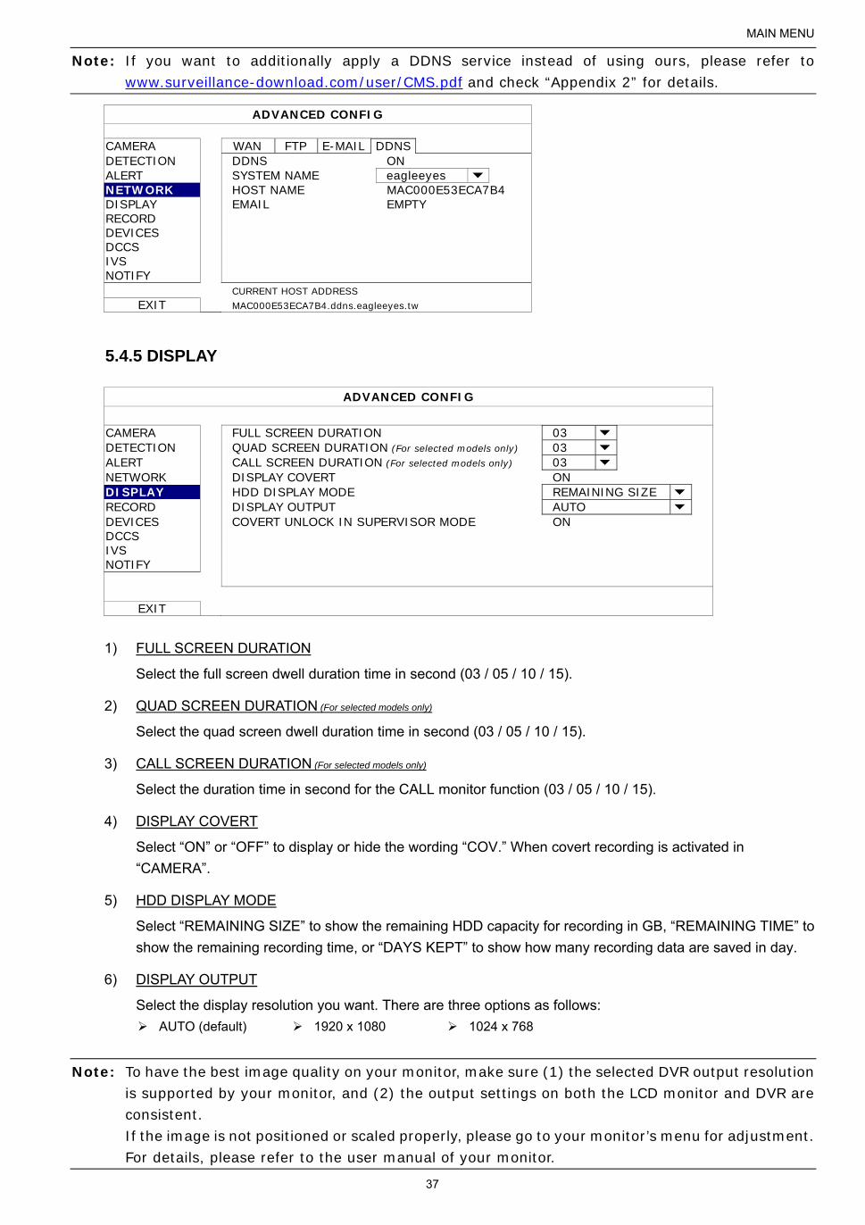
MAIN MENU
37
Note: If you want to additionally apply a DDNS service instead of using ours, please refer to www.surveillance-download.com/user/CMS.pdf and check “Appendix 2” for details.
ADVANCED CONFIG
CAMERA WAN FTP E-MAIL DDNS DETECTION DDNS ON ALERT SYSTEM NAME eagleeyes NETWORK HOST NAME MAC000E53ECA7B4 DISPLAY EMAIL EMPTY RECORD DEVICES DCCS IVS NOTIFY
CURRENT HOST ADDRESS EXIT MAC000E53ECA7B4.ddns.eagleeyes.tw
5.4.5 DISPLAY
ADVANCED CONFIG
CAMERA FULL SCREEN DURATION 03 DETECTION QUAD SCREEN DURATION (For selected models only) 03 ALERT CALL SCREEN DURATION (For selected models only) 03 NETWORK DISPLAY COVERT ON DISPLAY HDD DISPLAY MODE REMAINING SIZE RECORD DISPLAY OUTPUT AUTO DEVICES COVERT UNLOCK IN SUPERVISOR MODE ON DCCS IVS NOTIFY
EXIT
1) FULL SCREEN DURATION
Select the full screen dwell duration time in second (03 / 05 / 10 / 15).
2) QUAD SCREEN DURATION (For selected models only)
Select the quad screen dwell duration time in second (03 / 05 / 10 / 15).
3) CALL SCREEN DURATION (For selected models only)
Select the duration time in second for the CALL monitor function (03 / 05 / 10 / 15).
4) DISPLAY COVERT
Select “ON” or “OFF” to display or hide the wording “COV.” When covert recording is activated in
“CAMERA”.
5) HDD DISPLAY MODE
Select “REMAINING SIZE” to show the remaining HDD capacity for recording in GB, “REMAINING TIME” to
show the remaining recording time, or “DAYS KEPT” to show how many recording data are saved in day.
6) DISPLAY OUTPUT
Select the display resolution you want. There are three options as follows:
AUTO (default) 1920 x 1080 1024 x 768
Note: To have the best image quality on your monitor, make sure (1) the selected DVR output resolution is supported by your monitor, and (2) the output settings on both the LCD monitor and DVR are consistent. If the image is not positioned or scaled properly, please go to your monitor’s menu for adjustment. For details, please refer to the user manual of your monitor.

MAIN MENU
38
7) COVERT UNLOCK IN SUPERVISOR MODE
Enable this function to allow the supervisor user to see live view even when the channel is set “COV.” to
“ON” in “ADVANCED CONFIG” “CAMERA”.
5.4.6 RECORD
Note: Please DO NOT change the date or time of your DVR after the recording function is activated. Otherwise, the recorded data will be disordered and you will not be able to find the recorded file to backup by time search. If users change the date or time accidentally when the recording function is activated, it’s recommended to clear all HDD data, and start recording again.
ADVANCED CONFIG
CAMERA MANUAL RECORD ON DETECTION EVENT RECORD ON ALERT TIMER RECORD ON NETWORK PRE-ALARM RECORD ON DISPLAY OVERWRITE ON RECORD KEEP DATA LIMIT (DAYS) OFF DEVICES RECORD CONFIG SETUP DCCS IVS NOTIFY
EXIT
1) MANUAL RECORD
Set the manual recording function on / off.
2) EVENT RECORD
Set the event recording function on / off.
3) TIMER RECORD
Set the timer recording function on / off.
4) PRE-ALARM RECORD
Select to enable or disable the pre-alarm function (ON / OFF).
When pre-alarm and event recording functions are both activated, the DVR will record 8MB data before an
alarm / motion event is triggered.
5) OVERWRITE
Select “ON” to overwrite previous recorded data in your hard disk when the hard disk is full. When this
function is on and the hard disk is full, the DVR will clear 8GB data from the oldest for continuous recording
without notice.
6) KEEP DATA LIMITS (DAYS)
Assign the maximum recording days from 01 to 31 after which all the recorded data will be removed, or
select “OFF” to disable this function.
7) RECORD CONFIG
Click “SETUP” to enter the setting page individually for manual record, event record and timer record.
For details, please refer to “5.1.1 GENERAL” at page 21.

MAIN MENU
39
5.4.7 DEVICES
ADVANCED CONFIG
CAMERA CH1 CH2 CH3 CH4 CH5 CH6 CH7 CH8 CH9 CH10 CH11 DETECTION DEVICE PTZ ALERT ID 00 NETWORK PROTOCOL NORMAL DISPLAY RATE 2400 RECORD DEVICES DCCS IVS NOTIFY
EXIT
1) DEVICE
For the PTZ camera, select “PTZ”.
For a zoom lens control camera:
The DVR will detect it automatically and display its model number here.
To configure the parameters for a zoom lens control camera, please refer to “5.4.8 DCCS” at page 39. Different zoom lens control cameras might have different parameter settings. For details, please refer to their own user manuals.
2) ID
Click the current value to set the ID number (0 ~ 255) for the connected PTZ camera if necessary.
Make sure the ID setting of the camera is the same as the setting here, or the DVR will not be able to control
the device.
Note: To know the default ID of the PTZ camera, please refer to its user manual.
3) PROTOCOL
Select NORMAL (our protocol), P-D (PELCO-D) or P-P (PELCO-P) protocol.
4) RATE
Select the baud rate for the connected PTZ camera (2400 / 4800 / 9600 / 19200 / 38400 / 57600 / 115200).
Make sure the baud rate setting of the camera is the same as the setting here, or the DVR will not be able to
control the device.
Note: To know the default baud rate of the PTZ camera, please refer to its user manual.
5.4.8 DCCS
Note: This function is for selected models only.
Note: DCCS is supported only for CH1. Make sure you’ve connected a DCCS-enabled camera to the video channel of CH1, and you see “ ” in the channel status bar.
ADVANCED CONFIG
CAMERA CH1 CH2 CH3 CH4 CH5 CH6 CH7 CH8 CH9 CH10 CH11 DETECTION DIAGNOSTIC START ALERT MENU SETUP NETWORK DISPLAY RECORD DEVICES DEVICE AVK523 DCCS CONNECTION OK IVS NOTIFY
EXIT
1) DIAGNOSTIC
Click “START” to start examining the DCCS signal transmission between the DVR and the camera. The
result will display in “CONNECTION”.

MAIN MENU
40
2) MENU
Click “SETUP” to configure the connected zoom lens control camera.
Different zoom lens control cameras might have different parameter settings. For details, please refer to their
own user manuals.
Note: While configuring the camera parameters, the DVR will switch to the corresponding channel, and you can simultaneously preview the effects for the settings.
3) DEVICE
Here shows the model number of the camera.
4) CONNECTION
Here shows the examining result for DCCS signal transmission between the DVR and camera. The
message is as follows:
MESSAGE SHOWN MEANING
CHECKING The DVR is checking the DCCS signal transmission between the DVR and camera.
OK The signal transmission is fine and the DCCS function works properly.
FAIL The signal transmission is too weak or not available for the DCCS function to work properly.
5.4.9 IVS
Note: This function is for selected models only.
Note: Before using the IVS function, make sure the event record function is enabled on your DVR.
IVS, Intelligent Video Surveillance, is the advanced application for motion detection, but more precise and smarter.
It can be applied to different situations with one of the following three modes: FLOW COUNTING, VIRTUAL
FENCE, and ONE WAY.
When anyone crosses the detection line (virtual fence), the recording will be on.
Note: Four camera channels are supported for this function.
ADVANCED CONFIG
CAMERA IVS1 IVS2 IVS3 IVS4 DETECTION CAMERA CH3 ALERT IVS MODE FLOW COUNTING NETWORK DISPLAY LINE OFF DISPLAY SENSITIVITY 07 RECORD RESET COUNT SUBMIT DEVICES VIRTUAL FENCE AREA SETUP DCCS SCENE CHANGE OFF IVS SCENE CHANGE LEVEL MIDDLE NOTIFY
EXIT
1) CAMERA
Select the camera channel that you want to use the IVS function.
2) IVS MODE
Select one of the following three modes depending on your environment:
MODE DESCRIPTION
FLOW COUNTING A virtual detection line is set to detect the moving direction of pedestrians for flow counting.
VIRTUAL FENCE A virtual detection line is set to detect intruders crossing the detection line, and an alarm will be triggered.
ONE WAY A virtual detection line is set to detect intruders from the specified direction, and an alarm will be triggered.

MAIN MENU
41
3) DISPLAY LINE
Select to display the detection line for IVS on the screen or not.
4) SENSITIVITY
Set the sensitivity for IVS from 00 ~ 15. The larger the value, the more sensitive the IVS will be.
5) RESET COUNT
Click “SUBMIT” to reset the flow counting number to 0 when the IVS mode is set to “FLOW COUNTING” and
activated.
6) VIRTUAL FENCE AREA
Click “SETUP” to draw the detection line for IVS, and set the detection direction from left to right, or right to
left. This area setting is the detection base for IVS MODE.
Note: There are some tips to draw the detection line. For details, please check www.surveillance-download.com/user/IVS_setup.pdf.
7) SCENE CHANGE
Select “ON” to trigger a motion event when the camera is sensed to be moved and the camera scene is
changed. At the same time, the icon “ ” will be also shown on the screen in addition to the motion icon
“ ”.
8) SCENE CHANGE LEVEL
Set the detection sensitivity for “SCENE CHANGE” to “HIGH”, “MIDDLE” or “LOW”.
IVS APPLICATION
FFLLOOWW CCOOUUNNTTIINNGG
Step1: Go to “VIRTUAL FENCE AREA” to draw a detection line with your mouse, and decide the
detection direction by selecting “REVERSE”.
Step2: Finish the IVS setting and return to the live view. The IVS icon “ ” will be shown on the status bar.
Click it to show the flow counting panel as follows.
When anyone walks across the detection line, the system will determine his movement is in or out, and add one count to the corresponding channel on the flow counting panel.
IN People coming from the opposite direction to the arrow mark.
OUT People coming from the same direction as the arrow mark.
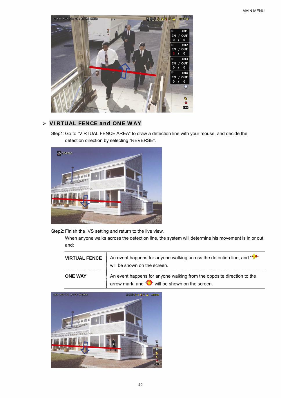
MAIN MENU
42
VVIIRRTTUUAALL FFEENNCCEE aanndd OONNEE WWAAYY
Step1: Go to “VIRTUAL FENCE AREA” to draw a detection line with your mouse, and decide the
detection direction by selecting “REVERSE”.
Step2: Finish the IVS setting and return to the live view.
When anyone walks across the detection line, the system will determine his movement is in or out,
and:
VIRTUAL FENCE An event happens for anyone walking across the detection line, and “ ”
will be shown on the screen.
ONE WAY An event happens for anyone walking from the opposite direction to the
arrow mark, and “ ” will be shown on the screen.

MAIN MENU
43
IVS STATISTICS
Press “LIST” on the DVR front panel, or click “ ” “ ” to enter the event search menu. Then, select
“STATISTIC” LIST
QUICK SEARCH CHANNEL 3 SELECTED RECORD ALL MOTION CH1 ALARM CH2 TIME CH3 HUMAN DETECTION CH4 IVS CH5 FULL STATISTIC EVENT TYPE 3 SELECTED ALL INFLOW OUTFLOW VIRTUAL FENCE ONEWAY MOTION TIME 2010/MAY/17 STATISTIC SUBMIT
EXIT
Set all the criteria you want to search, and click “SUBMIT” in “STATISTIC” to show the event statistics by
DAY in LIST (default) or CHART.
To check the statistics in the bar chart, click “CHART”.
To switch to the MONTH or HOUR view, click “DAY” at the bottom.
List View
IVS STATISTIC LIST CHART HOUR COUNT 00:00 – 00:59 0 01:00 – 01:59 0 02:00 – 02:59 0 03:00 – 03:59 0 04:00 – 04:59 0 05:00 – 05:59 10 06:00 – 06:59 0 07:00 – 07:59 0 08:00 – 08:59 5 09:00 – 09:59 0 2010/MAY/17 DAY EXIT

MAIN MENU
44
Chart View
IVS STATISTIC LIST CHART 30
24
18
12
6
CO
UN
T
0
0 1 2 3 4 5 6 7 8 9 10
11
12
13
14
15
16
17
18
19
20
21
22
23
HOUR 2010/MAY/17 DAY EXIT
5.4.10 NOTIFY
You can configure this DVR to send notifications for certain events to mobile devices with our mobile app,
EagleEyes, installed, or to the specified E-mail address(es).
PUSH VIDEO
Note: This function is for selected models only, and the supported channels depend on the model you have.
Before using this function, make sure:
An external alarm is connected to PUSH VIDEO Alarm in terminal on the rear panel.
You have a iPhone, iPad, or Android mobile phone or tablet.
You have subscribed the mobile network service from your mobile service provider.
The mobile app, EagleEyes, is installed in your mobile device. For details, please refer to “APPENDIX 4 MOBILE SURVEILLANCE
VIA EAGLEEYES” at page 80.
You have configured EagleEyes to access this DVR, and Push Video is enabled. For details, please refer to “APPENDIX 5 SET
PUSH VIDEO” at page 81.
You’ll get an active event notification with video telling you the occurrence of alarm event(s).
ADVANCED CONFIG
CANERA PUSH VIDEO PUSH STATUS MESSAGE MAIL VIDEO MAIL DETECTION GUARD ON ALERT CH01 ALARM OFF / INTERNAL ALARM CH1 NETWORK CH02 ALARM OFF CH2 DISPLAY CH03 ALARM N.O. office RECORD CH04 ALARM OFF CH4 DEVICES DCCS IVS NOTIFY
EXIT
1) GUARD
Select to enable or disable Push Video function (ON / OFF).
Select to activate the Push Video function (ON / OFF). Or it could also be activated later from your iPhone,
iPad or Android mobile device.

MAIN MENU
45
Note: For details about DVR operations from your mobile device, please visit http://www.eagleeyescctv.com.
2) ALARM TYPE
Select the external alarm type to “ALARM NO.” or “ALARM N.C.”
For CH01, there’s one more option of “INTERNAL ALARM”. This option should be selected only when the
camera connected to CH1 is a human detection camera.
3) CH1 ~ 4
Enter the text you want to see when your iPhone, iPad or Android mobile device receives Push Video. The
default text is the channel number.
PUSH STATUS
Note: This function is for selected models only.
Before using this function, make sure:
You have iPhone, iPad, or Android mobile phone or tablet. You have subscribed the mobile network service from your mobile service provider.
The mobile app, EagleEyes, is installed in your mobile device. For details, please refer to “APPENDIX 4 MOBILE SURVEILLANCE
VIA EAGLEEYES” at page 80.
You have configured EagleEyes to access this DVR, and Push Video is enabled. For details, please refer to “APPENDIX 5 SET
PUSH VIDEO” at page 81.
You’ll get a text message telling you the occurrence of selected system event(s).
ADVANCED CONFIG
CANERA PUSH VIDEO PUSH STATUS MESSAGE MAIL VIDEO MAIL DETECTION ACTION ON ALERT EVENT ALL NETWORK VIDEO LOSS DISPLAY HDD FULL RECORD POWER ON DEVICES HDD (CLEAR / NO HDD / OVER TEMPERATURE) DCCS NET LOGIN IVS KEY UNLOCK NOTIFY UPS SYSTEM ABNORMAL
EXIT
Step1: Switch “ACTION” to “ON”.
Step2: Select the system event(s) you want to get notified via your mobile device.
Step3: Enable “PUSH STATUS” in EagleEyes on your mobile device, and try to trigger an alarm event to see if
you’ll get Push Status.
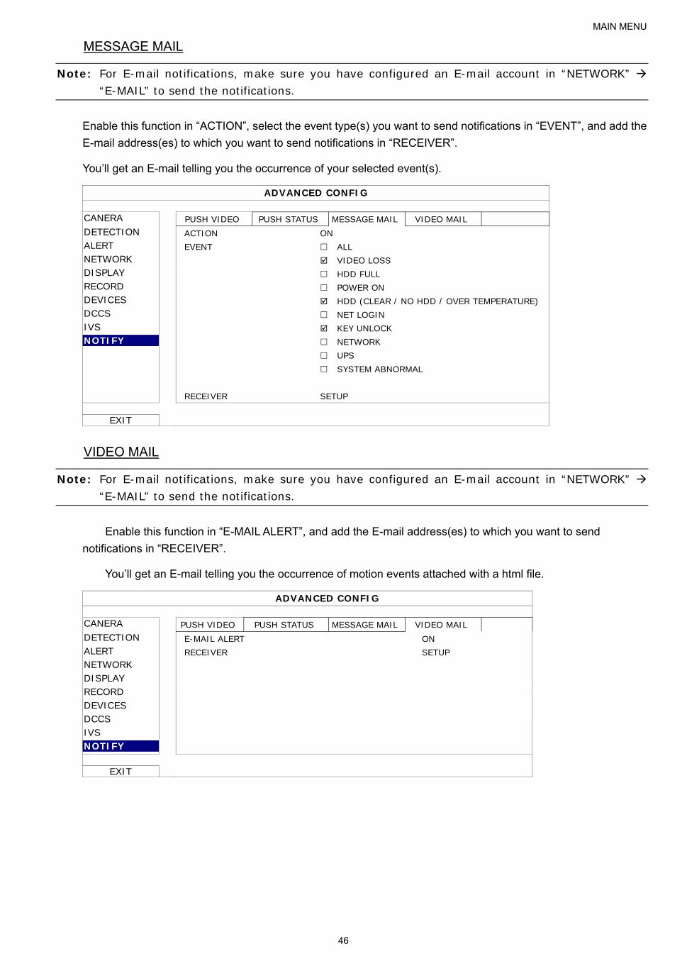
MAIN MENU
46
MESSAGE MAIL
Note: For E-mail notifications, make sure you have configured an E-mail account in “NETWORK” “E-MAIL” to send the notifications.
Enable this function in “ACTION”, select the event type(s) you want to send notifications in “EVENT”, and add the
E-mail address(es) to which you want to send notifications in “RECEIVER”.
You’ll get an E-mail telling you the occurrence of your selected event(s).
ADVANCED CONFIG
CANERA PUSH VIDEO PUSH STATUS MESSAGE MAIL VIDEO MAIL DETECTION ACTION ON ALERT EVENT ALL NETWORK VIDEO LOSS DISPLAY HDD FULL RECORD POWER ON DEVICES HDD (CLEAR / NO HDD / OVER TEMPERATURE) DCCS NET LOGIN IVS KEY UNLOCK NOTIFY NETWORK UPS SYSTEM ABNORMAL RECEIVER SETUP
EXIT
VIDEO MAIL
Note: For E-mail notifications, make sure you have configured an E-mail account in “NETWORK” “E-MAIL” to send the notifications.
Enable this function in “E-MAIL ALERT”, and add the E-mail address(es) to which you want to send
notifications in “RECEIVER”.
You’ll get an E-mail telling you the occurrence of motion events attached with a html file.
ADVANCED CONFIG
CANERA PUSH VIDEO PUSH STATUS MESSAGE MAIL VIDEO MAIL DETECTION E-MAIL ALERT ON ALERT RECEIVER SETUP NETWORK DISPLAY RECORD DEVICES DCCS IVS NOTIFY
EXIT

MAIN MENU
47
How to check video recording
Step1: Open the html file attached.
Note: Please accept to install ActiveX control on your computer.
Step2: Enter the user name and password to log into this DVR, and select the channel you want.
Step3: Click “Open” to download the motion recording to your computer and start playing.
5.5 SCHEDULE SETTING
5.5.1 RECORD
Select “ON” to enable record timer, and select the day and time for this function.
SCHEDULE SETTING
RECORD RECORD TIMER ON DETECTION 0 2 4 6 8 10 12 14 16 18 20 22 24
ALARM SUN MON TUE WED THU FRI SAT
EXIT
X axis 0 ~ 24 hours. Each time bar is 30 minutes.
Y axis Monday ~ Sunday.

MAIN MENU
48
5.5.2 DETECTION
Select “ON” to enable detection timer, and select the day and time for this function.
SCHEDULE SETTING
RECORD DETECTION TIMER ON DETECTION 0 2 4 6 8 10 12 14 16 18 20 22 24
ALARM SUN MON TUE WED THU FRI SAT
EXIT
X axis 0 ~ 24 hours. Each time bar is 30 minutes.
Y axis Monday ~ Sunday.
5.5.3 ALARM
Select “ON” to enable alarm timer, and select the day and time for this function.
SCHEDULE SETTING
RECORD ALARM TIMER ON DETECTION 0 2 4 6 8 10 12 14 16 18 20 22 24
ALARM SUN MON TUE WED THU FRI SAT
EXIT
X axis 0 ~ 24 hours. Each time bar is 30 minutes.
Y axis Monday ~ Sunday.

REMOTE OPERATION
49
6. REMOTE OPERATION
You can also control the DVR remotely via the supplied licensed software “Video Viewer”, web browser, and your
smart phones.
Note: For more details about mobile surveillance via your smart phones, please visit our official website www.eagleeyescctv.com, or download the instructions of EagleEyes installation and configuration from www.surveillance-download.com/user/eagleeyes_quick.pdf.
6.1 Supplied Licensed Software
The sections below describe frequently-used functions of the Video Viewer. For details about this software and
network settings, please download its extended user manual from the following link:
http://www.surveillance-download.com/user/CMS.pdf
6.1.1 Installation & Network Connection
1) Install the software
Step1: Place the supplied CD into your CD-ROM or DVD-ROM drive. The program will be automatically run.
Step2: Click “Video Viewer” to install the program, or click "Download the latest manuals and programs” to
download the latest version of Video Viewer from the Internet.
Step3: Follow the on-screen instructions to finish the installation. When the installation is completed, a
shortcut icon “ ” will be placed on your PC desktop.
2) Network Connection
LLooccaall CCoonnnneeccttiioonn ((vviiaa LLAANN))
LAN is used when it’s the first time to remotely access the DVR and you need to configure the network
setting of your DVR based on your network type in advance.
a) Connect the DVR to your PC via a RJ45 network cable. The default DVR values are as follows:
Item Default Value
IP address 192.168.1.10
User name admin
Password admin
Port 80
b) Set the PC’s IP address as “192.168.1.XXX” (1~255, except 10) in order to make the PC and DVR under
the same domain.
c) Double-click “ ” on your PC desktop to enter the control panel. By defaults, the “Address Book” panel
will be displayed on the right side of the control panel.
d) Click “ ” “ ” to key in the default IP address, user name, password, and port number of the DVR you intend to connect.
OR
Click “ ” “ ” to search the available IP address(es) of other DVR(s) under the same domain as your PC’s IP address. The found address(es) will be listed, and can be added into the address book
by clicking “ ”.
e) Double-click the IP address you just added into the address book to log in.
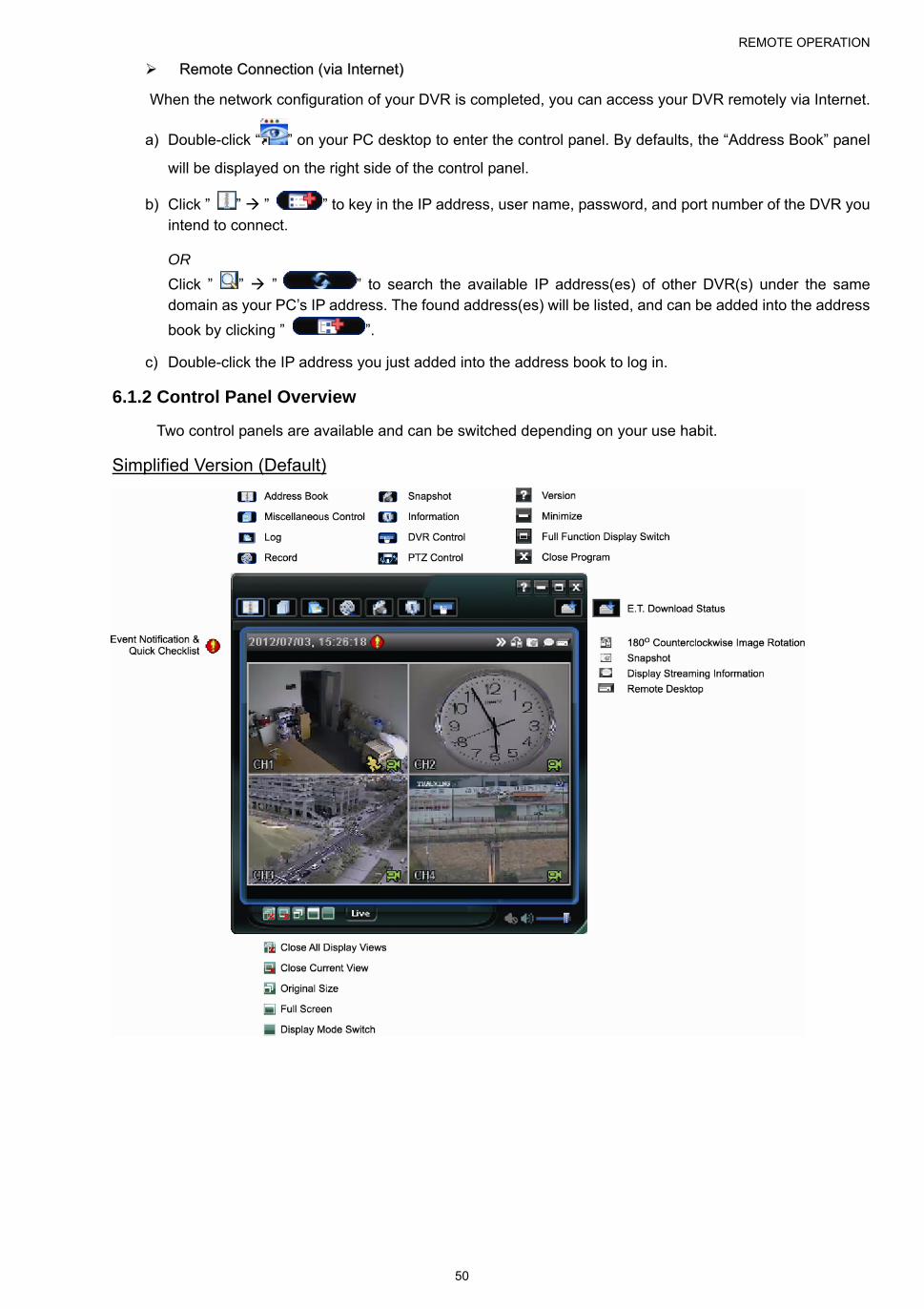
REMOTE OPERATION
50
RReemmoottee CCoonnnneeccttiioonn ((vviiaa IInntteerrnneett))
When the network configuration of your DVR is completed, you can access your DVR remotely via Internet.
a) Double-click “ ” on your PC desktop to enter the control panel. By defaults, the “Address Book” panel
will be displayed on the right side of the control panel.
b) Click ” ” ” ” to key in the IP address, user name, password, and port number of the DVR you intend to connect.
OR
Click ” ” ” ” to search the available IP address(es) of other DVR(s) under the same domain as your PC’s IP address. The found address(es) will be listed, and can be added into the address
book by clicking ” ”.
c) Double-click the IP address you just added into the address book to log in.
6.1.2 Control Panel Overview
Two control panels are available and can be switched depending on your use habit.
Simplified Version (Default)

REMOTE OPERATION
51
Full Function Version
Main Button Overview
Button
Simplified Full FunctionFunction Description
Address Book Click to show the predefined IP address(es). You can add, remove or
search the IP address to log in the DVR remotely.
Remote
Config Click to go into the detailed DVR setting.
Record
Setting Click to go to the detailed record setting.
Miscellaneous Control
Custom
Setting
Click to choose the language of this program. The
language change will take effect when this
program is closed and executed again.
Log Click to view all event and recording logs, search the desired log(s) by
date, or playback the recording of the selected log.
/ / Record / Record Stop Click to start / stop the manual recording.
Snapshot Click to take a snapshot of the current view. The snapshot will be saved
in the path you specified in “Record Setting”.
Information Click to show the current network connection details.
DVR Control Click to go to the DVR control panel to operate the DVR remotely.
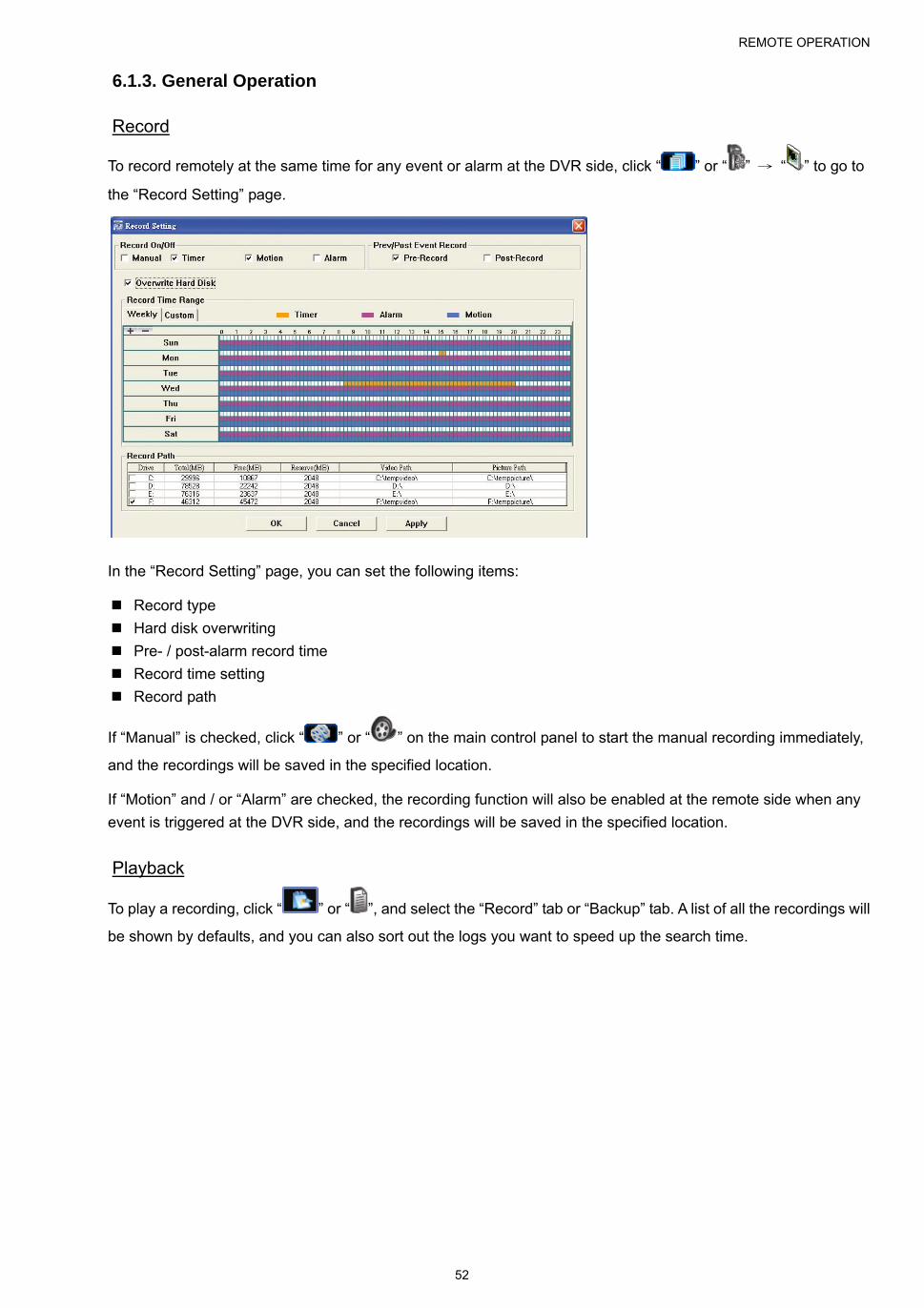
REMOTE OPERATION
52
6.1.3. General Operation
Record
To record remotely at the same time for any event or alarm at the DVR side, click “ ” or “ ” → “ ” to go to
the “Record Setting” page.
In the “Record Setting” page, you can set the following items:
Record type
Hard disk overwriting
Pre- / post-alarm record time
Record time setting
Record path
If “Manual” is checked, click “ ” or “ ” on the main control panel to start the manual recording immediately,
and the recordings will be saved in the specified location.
If “Motion” and / or “Alarm” are checked, the recording function will also be enabled at the remote side when any
event is triggered at the DVR side, and the recordings will be saved in the specified location.
Playback
To play a recording, click “ ” or “ ”, and select the “Record” tab or “Backup” tab. A list of all the recordings will
be shown by defaults, and you can also sort out the logs you want to speed up the search time.
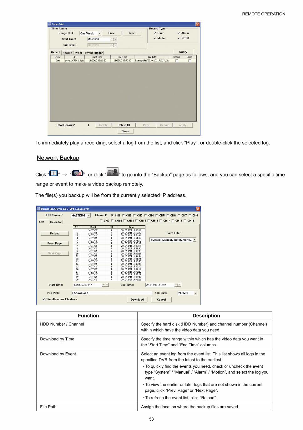
REMOTE OPERATION
53
To immediately play a recording, select a log from the list, and click “Play”, or double-click the selected log.
Network Backup
Click “ ” → “ ”, or click “ ” to go into the “Backup” page as follows, and you can select a specific time
range or event to make a video backup remotely.
The file(s) you backup will be from the currently selected IP address.
Function Description
HDD Number / Channel Specify the hard disk (HDD Number) and channel number (Channel)
within which have the video data you need.
Download by Time Specify the time range within which has the video data you want in
the “Start Time” and “End Time” columns.
Download by Event Select an event log from the event list. This list shows all logs in the
specified DVR from the latest to the earliest.
‧To quickly find the events you need, check or uncheck the event
type “System” / “Manual” / “Alarm” / “Motion”, and select the log you
want.
‧To view the earlier or later logs that are not shown in the current
page, click “Prev. Page” or “Next Page”.
‧To refresh the event list, click “Reload”.
File Path Assign the location where the backup files are saved.

REMOTE OPERATION
54
Function Description
Simultaneous Playback To view the backup images simultaneously when the download
process is in progress, select the checkbox “Simultaneous Playback”.
You will see the backup images while the images are being
downloaded to the PC or notebook.
To simply backup images without previewing, deselect the checkbox
“Simultaneous Playback”. You will only see a message box indicating
the total time needed, the current status and the saving location.
Download / Cancel Click “Download” to start or “Cancel” to discard the video backup.
Firmware Upgrade
This function is used to grade your DVR for function scalability.
Note: Before using this function, make sure you have the correct upgrade files provided by your installer or distributor.
Step1: Click “ ”, and select the IP address of your device in the address book.
Step2: Click “ ” to show the upgrade page, “Update Server”.
Step3: Click “Add” to browse to the upgrade files.
Step4: Click “Upgrade Firmware” to start firmware upgrade.
Note: It takes a few minutes to finish the upgrade process. Do not disconnect the power during firmware upgrade, or the upgrade may be failed. The device will reboot after the upgrade.
Step5: Select the IP address of the device and click “ ” again to check if the firmware is upgraded.
6.1.4. E-Map
Video Viewer is also a Central Management System (CMS) software, which allows network device control &
management for up to 16 devices simultaneously.
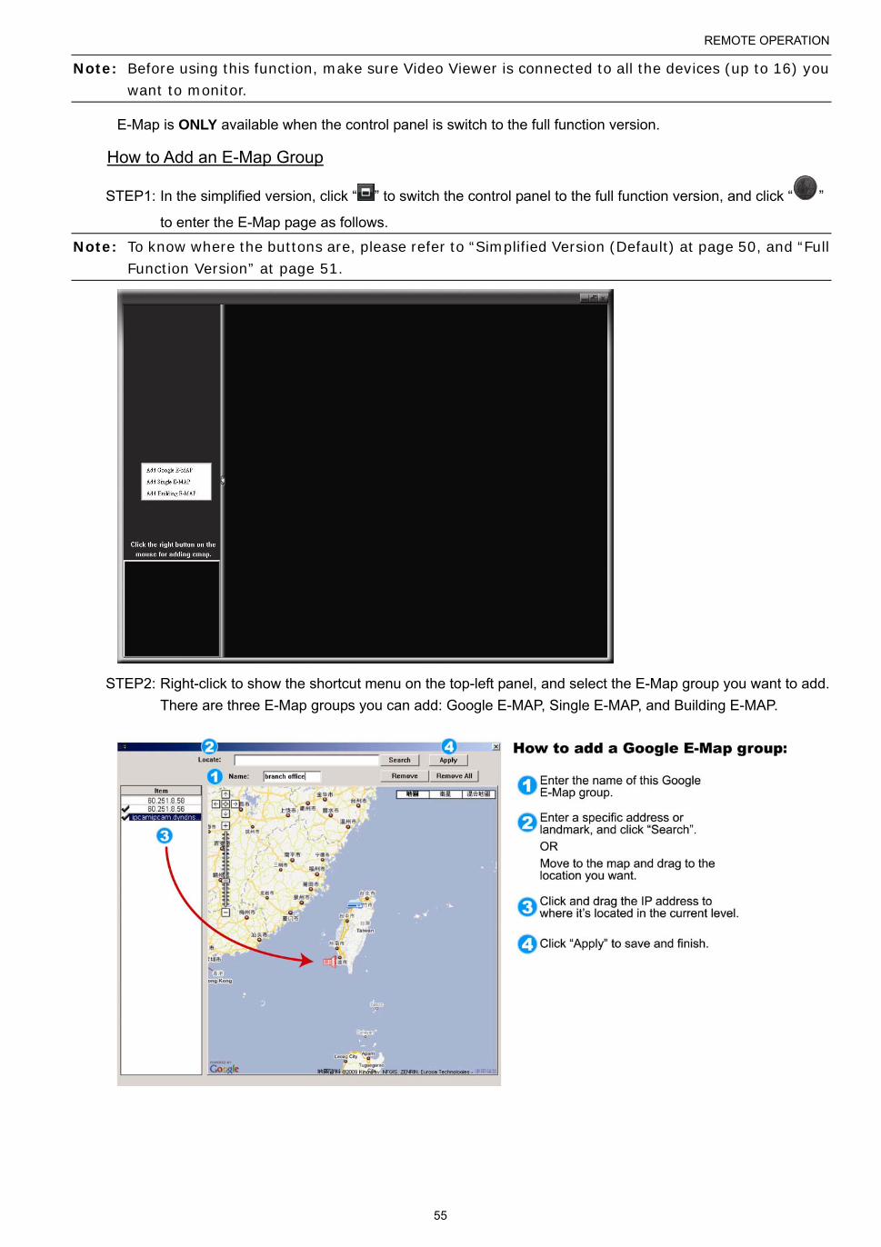
REMOTE OPERATION
55
Note: Before using this function, make sure Video Viewer is connected to all the devices (up to 16) you want to monitor.
E-Map is ONLY available when the control panel is switch to the full function version.
How to Add an E-Map Group
STEP1: In the simplified version, click “ ” to switch the control panel to the full function version, and click “ ”
to enter the E-Map page as follows.
Note: To know where the buttons are, please refer to “Simplified Version (Default) at page 50, and “Full Function Version” at page 51.
STEP2: Right-click to show the shortcut menu on the top-left panel, and select the E-Map group you want to add.
There are three E-Map groups you can add: Google E-MAP, Single E-MAP, and Building E-MAP.

REMOTE OPERATION
56
STEP3: When the E-Map group is created, you will see the tree on the top-left panel, showing all the devices
you’ve added to this group.

REMOTE OPERATION
57
Icon Description
The connected device is camera. When it’s selected, it will become red.
The connected device is DVR. When it’s selected, it will become red.
For any motion or alarm event, it will appear on the screen to catch your attention. To know what’s happening quickly, double-click the device icon on the E-Map to show the live view.
How to Edit / Remove an Existing E-Map Group
For Google E-Map Group
Right-click on the group name to show the shortcut menu list, and select “Edit E-MAP” or “Remove E-MAP” as needed.
You can also add a single E-Map group (Add Single E-MAP) or Building E-Map group (Add Building E-MAP) into the existing Google E-Map group.

REMOTE OPERATION
58
For Single E-Map Group
Right-click on the group name to show the shortcut menu list, and select “Edit E-MAP” or “Remove E-MAP” as needed.
For Building E-Map Group
Right-click on the group name to show the shortcut menu list, and select “Edit Building E-MAP” or “Remove E-MAP” as needed.

REMOTE OPERATION
59
To edit or remove a certain level of the building E-Map group, right click on the level name, and select “Edit E-MAP” or “Remove E-MAP” as needed.

REMOTE OPERATION
60
6.2 Web Browser
You can view the images or operate your DVR with a web browser, for example, Microsoft Internet Explorer.
Note: The supported PC operation systems are Windows 7, Vista & XP.
Note: To use Mozilla Firefox or Google Chrome for remote access, please go to Apple’s official website (http://www.apple.com) to download and install QuickTime first.
Note: The illustration below is just for your reference and may be different from what you actually see. Some functions and buttons are for selected models or certain user levels only.
Step 1: Key in the IP address used by your DVR in the URL address box, such as 60.121.46.236, and press Enter.
You will be prompted to enter the user name and password to access the DVR.
If the port number your DVR used is NOT 80, you need to key in the port number additionally. The format is
ipaddress:portnum. For example, for IP address 60.121.46.236 and port No. 888, please key
in ”http://60.121.46.236:888” into the URL address box, and press “Enter”.
Step 2: Enter the user name and password, the same as the ones used at AP login, and click “OK”. You will see a
similar screen as the following when the login information is correct.
Icon Description
Click to go to the live view of the DVR.
Click to enter the playback panel where you can search or select the event you want to play and download to your PC simultaneously. For details, please refer to “6.2.1 Event Playback & Download” at page 61.
Click to go to the detailed DVR setting.
Click to enter the PTZ mode.
Video / Audio Control
Format H.264 / QuickTime
QuickTime is Apple Inc.’s multimedia software. You need to have QuickTime installed in you operation system first. When “QuickTime” is selected, you will be promoted to enter the user name and password to access the server of the DVR.
Quality BEST / HIGH / NORMAL / BASIC
Select the image quality.
Resolution 4 CIF / CIF
Select the image resolution (4CIF: 704*480 / CIF: 352*240)
Audio Select the audio channel you want for listening to the live audio.
Note: Your camera must support audio recording, and connect to the video channel which supports audio recording and the audio input of the DVR. For details, please refer to “1.3 Rear Panel” at page 2.
means mute.
To disable the mute status, click this icon again and select the audio channel you want.

REMOTE OPERATION
61
Icon Description
Channel Control
Channel Selection
(1~16) Click one of the number to switch to the channel you want to see in full screen.
/ Click to go to the previous / next channel, or change setting.
Click to take a snapshot of the current view, and save it to the specified path in your PC set in “ ”
“General”.
:
Click to display four channels at a time. /
:
Click to display each channel one by one, starting from CH1. When the last channel is displayed, it will start from CH1 again.
To exit from this display mode, press any other channel display button.
/ / Click to show 4-cut / 9-cut / 16-cut display.
Playback Control
Increase the speed for fast rewind. Click once to get 4X speed rewind and click twice to get 8X speed, etc., and the maximum speed is 32X.
Increase the speed for fast forward. Click once to get 4X speed forward and click twice to get 8X speed, etc., and the maximum speed is 32X.
Click to play the current video clip.
Click to pause the video playback.
Click to stop the video playback.
Click to play the video clip slowly, once to get 4X slower, twice get 8X slower.
IVS Panel*
This button is enabled only when the IVS mode is “Flow Counting”. Click to show the detection line.
Click to enter the IVS statistics page. For details, please refer to “6.2.2 IVS Statistics” at page 63.
* For selected models only
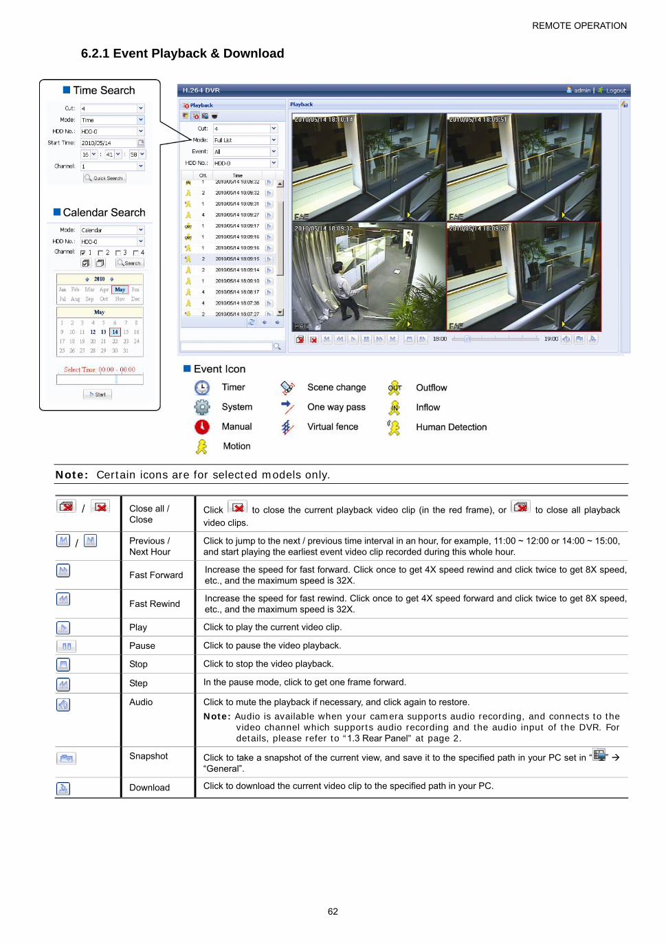
REMOTE OPERATION
62
6.2.1 Event Playback & Download
Note: Certain icons are for selected models only.
/ Close all / Close
Click to close the current playback video clip (in the red frame), or to close all playback
video clips.
/ Previous / Next Hour
Click to jump to the next / previous time interval in an hour, for example, 11:00 ~ 12:00 or 14:00 ~ 15:00, and start playing the earliest event video clip recorded during this whole hour.
Fast Forward Increase the speed for fast forward. Click once to get 4X speed rewind and click twice to get 8X speed, etc., and the maximum speed is 32X.
Fast Rewind Increase the speed for fast rewind. Click once to get 4X speed forward and click twice to get 8X speed, etc., and the maximum speed is 32X.
Play Click to play the current video clip.
Pause Click to pause the video playback.
Stop Click to stop the video playback.
Step In the pause mode, click to get one frame forward.
Audio Click to mute the playback if necessary, and click again to restore.
Note: Audio is available when your camera supports audio recording, and connects to the video channel which supports audio recording and the audio input of the DVR. For details, please refer to “1.3 Rear Panel” at page 2.
Snapshot Click to take a snapshot of the current view, and save it to the specified path in your PC set in “ ” “General”.
Download Click to download the current video clip to the specified path in your PC.

REMOTE OPERATION
63
6.2.2 IVS Statistics
Note: This function is for selected models only.

APPENDIX 1 SPECIFICATIONS
64
APPENDIX 1 SPECIFICATIONS
16CH Models
Model 1 Model 2 Model 3 Model 4 Video
Video System NTSC / PAL (auto detection)
Video Compression Format H.264
Video Input 16 channels (Composite video signal 1 Vp-p 75Ω BNC)
Video Loop Output 16 channels (Composite video signal 1 Vp-p 75Ω BNC) NO
Video Output BNC YES (Call monitor for sequence display) NO
VGA YES (Full HD display)
HDMI YES (Full HD display)
Dual Video Output YES
Record & Backup
Maximum Recording Rate 960H --
960 x 480 pixels with 360 IPS <NTSC> /
960 x 576 pixels with 360 IPS <PAL>
--
Frame 704×480 pixels with 480 IPS <NTSC> / 704×576 pixels with 400 IPS <PAL>
Field 704x240 pixels with 480 IPS <NTSC> / 704×288 pixels with 400 IPS <PAL>
CIF 352×240 pixels with 480 IPS <NTSC> / 352×288 pixels with 400 IPS <PAL>
Image Resolution Frame / Field / CIF 960H / Frame / Field / CIF Frame / Field / CIF
Recording Mode Manual / Timer / Motion / Alarm / Remote
Pre-alarm Recording YES
Quick Search Time / Motion / Alarm search mode
Backup Device USB 2.0 flash drive / Network
DVD Writer (Optional) / USB 2.0 flash drive /
Network USB 2.0 flash drive / Network
Audio
Audio Input 4 audio inputs
Audio Output 2 audio outputs (Mono)
General
Hard Disk Storage Accommodates 2 SATA HDDs (1 HDD capacity up to 3TB)
SATA Interface YES
eSATA Interface YES (For external disk array connection)
Image Quality Setting SUPER BEST / BEST / HIGH / NORMAL
USB Mouse Control YES
Motion Detection Area 16 × 12 grids per channel
Motion Detection Sensitivity 3 adjustable parameters for accurate detection
Event Notification Push Video / FTP / E-Mail
Picture Zoom 2X digital zoom
PTZ Control YES
Alarm I/O 16 inputs (4 inputs for Push Video), 1 output
IR Remote Control YES (IR receiver built-in)
Key Lock (Password Protection) YES
User Level 4 user levels for different access privilege
Video Loss Detection YES
Camera Title Supports up to 12 letters
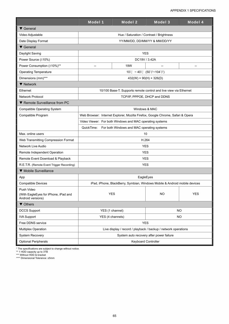
APPENDIX 1 SPECIFICATIONS
65
Model 1 Model 2 Model 3 Model 4 General
Video Adjustable Hue / Saturation / Contrast / Brightness
Date Display Format YY/MM/DD, DD/MM/YY & MM/DD/YY
General
Daylight Saving YES
Power Source (±10%) DC19V / 3.42A
Power Consumption (±10%)** -- 19W -- --
Operating Temperature 10 ~ 40 (50~104)
Dimensions (mm)*** 432(W) × 90(H) × 326(D)
Network
Ethernet 10/100 Base-T. Supports remote control and live view via Ethernet
Network Protocol TCP/IP, PPPOE, DHCP and DDNS
Remote Surveillance from PC
Compatible Operating System Windows & MAC
Compatible Program Web Browser: Internet Explorer, Mozilla Firefox, Google Chrome, Safari & Opera
Video Viewer: For both Windows and MAC operating systems
QuickTime: For both Windows and MAC operating systems
Max. online users 10
Web Transmitting Compression Format H.264
Network Live Audio YES
Remote Independent Operation YES
Remote Event Download & Playback YES
R.E.T.R. (Remote Event Trigger Recording) YES
Mobile Surveillance
App EagleEyes
Compatible Devices iPad, iPhone, BlackBerry, Symbian, Windows Mobile & Android mobile devices
Push Video
(With EagleEyes for iPhone, iPad and Android versions)
YES NO YES
Others
DCCS Support YES (1 channel) NO
IVA Support YES (4 channels) NO
Free DDNS service YES
Multiplex Operation Live display / record / playback / backup / network operations
System Recovery System auto recovery after power failure
Optional Peripherals Keyboard Controller
* The specifications are subject to change without notice. ** 1 HDD capacity up to 3TB *** Without HDD & bracket **** Dimensional Tolerance: ±5mm
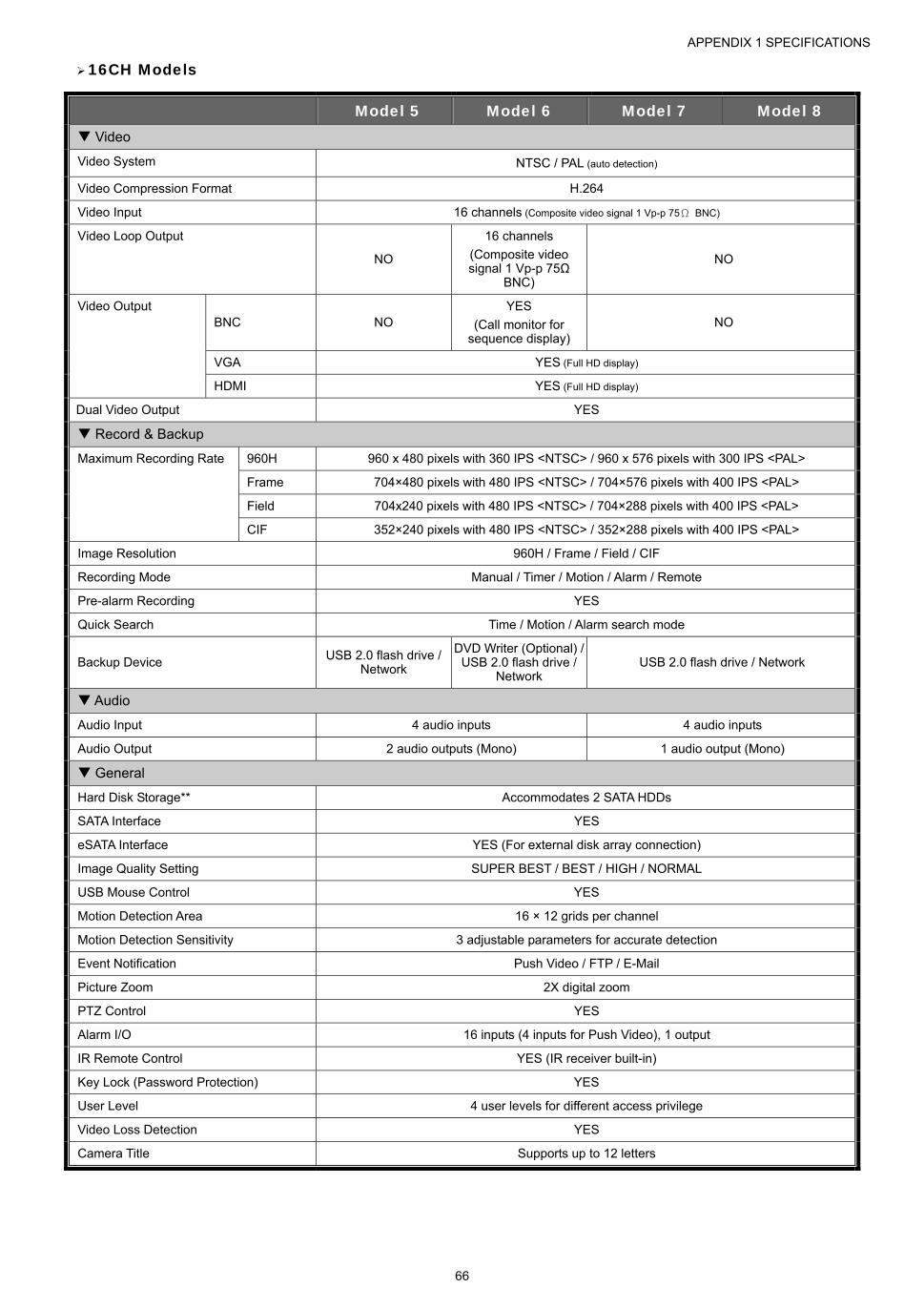
APPENDIX 1 SPECIFICATIONS
66
16CH Models
Model 5 Model 6 Model 7 Model 8 Video
Video System NTSC / PAL (auto detection)
Video Compression Format H.264
Video Input 16 channels (Composite video signal 1 Vp-p 75Ω BNC)
Video Loop Output
NO
16 channels
(Composite video signal 1 Vp-p 75Ω
BNC)
NO
Video Output BNC NO
YES
(Call monitor for sequence display)
NO
VGA YES (Full HD display)
HDMI YES (Full HD display)
Dual Video Output YES
Record & Backup
Maximum Recording Rate 960H 960 x 480 pixels with 360 IPS <NTSC> / 960 x 576 pixels with 300 IPS <PAL>
Frame 704×480 pixels with 480 IPS <NTSC> / 704×576 pixels with 400 IPS <PAL>
Field 704x240 pixels with 480 IPS <NTSC> / 704×288 pixels with 400 IPS <PAL>
CIF 352×240 pixels with 480 IPS <NTSC> / 352×288 pixels with 400 IPS <PAL>
Image Resolution 960H / Frame / Field / CIF
Recording Mode Manual / Timer / Motion / Alarm / Remote
Pre-alarm Recording YES
Quick Search Time / Motion / Alarm search mode
Backup Device USB 2.0 flash drive / Network
DVD Writer (Optional) / USB 2.0 flash drive /
Network USB 2.0 flash drive / Network
Audio
Audio Input 4 audio inputs 4 audio inputs
Audio Output 2 audio outputs (Mono) 1 audio output (Mono)
General
Hard Disk Storage** Accommodates 2 SATA HDDs
SATA Interface YES
eSATA Interface YES (For external disk array connection)
Image Quality Setting SUPER BEST / BEST / HIGH / NORMAL
USB Mouse Control YES
Motion Detection Area 16 × 12 grids per channel
Motion Detection Sensitivity 3 adjustable parameters for accurate detection
Event Notification Push Video / FTP / E-Mail
Picture Zoom 2X digital zoom
PTZ Control YES
Alarm I/O 16 inputs (4 inputs for Push Video), 1 output
IR Remote Control YES (IR receiver built-in)
Key Lock (Password Protection) YES
User Level 4 user levels for different access privilege
Video Loss Detection YES
Camera Title Supports up to 12 letters
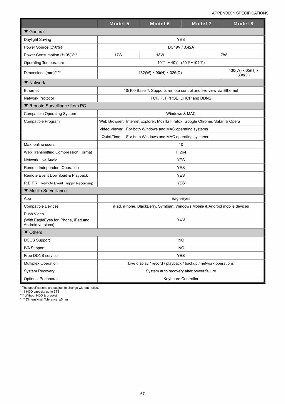
APPENDIX 1 SPECIFICATIONS
67
Model 5 Model 6 Model 7 Model 8 General
Daylight Saving YES
Power Source (±10%) DC19V / 3.42A
Power Consumption (±10%)*** 17W 18W 17W
Operating Temperature 10 ~ 40 (50~104)
Dimensions (mm)**** 432(W) × 90(H) × 326(D) 430(W) x 65(H) x
338(D)
Network
Ethernet 10/100 Base-T. Supports remote control and live view via Ethernet
Network Protocol TCP/IP, PPPOE, DHCP and DDNS
Remote Surveillance from PC
Compatible Operating System Windows & MAC
Compatible Program Web Browser: Internet Explorer, Mozilla Firefox, Google Chrome, Safari & Opera
Video Viewer: For both Windows and MAC operating systems
QuickTime: For both Windows and MAC operating systems
Max. online users 10
Web Transmitting Compression Format H.264
Network Live Audio YES
Remote Independent Operation YES
Remote Event Download & Playback YES
R.E.T.R. (Remote Event Trigger Recording) YES
Mobile Surveillance
App EagleEyes
Compatible Devices iPad, iPhone, BlackBerry, Symbian, Windows Mobile & Android mobile devices
Push Video
(With EagleEyes for iPhone, iPad and Android versions)
YES
Others
DCCS Support NO
IVA Support NO
Free DDNS service YES
Multiplex Operation Live display / record / playback / backup / network operations
System Recovery System auto recovery after power failure
Optional Peripherals Keyboard Controller
* The specifications are subject to change without notice. ** 1 HDD capacity up to 3TB *** Without HDD & bracket **** Dimensional Tolerance: ±5mm
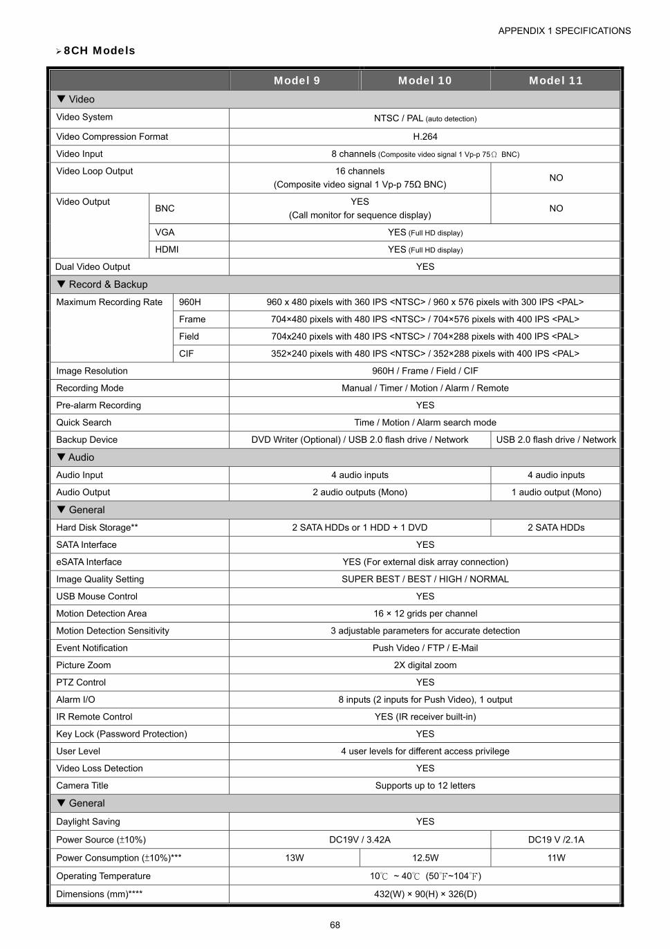
APPENDIX 1 SPECIFICATIONS
68
8CH Models
Model 9 Model 10 Model 11 Video
Video System NTSC / PAL (auto detection)
Video Compression Format H.264
Video Input 8 channels (Composite video signal 1 Vp-p 75Ω BNC)
Video Loop Output 16 channels
(Composite video signal 1 Vp-p 75Ω BNC) NO
Video Output BNC
YES
(Call monitor for sequence display) NO
VGA YES (Full HD display)
HDMI YES (Full HD display)
Dual Video Output YES
Record & Backup
Maximum Recording Rate 960H 960 x 480 pixels with 360 IPS <NTSC> / 960 x 576 pixels with 300 IPS <PAL>
Frame 704×480 pixels with 480 IPS <NTSC> / 704×576 pixels with 400 IPS <PAL>
Field 704x240 pixels with 480 IPS <NTSC> / 704×288 pixels with 400 IPS <PAL>
CIF 352×240 pixels with 480 IPS <NTSC> / 352×288 pixels with 400 IPS <PAL>
Image Resolution 960H / Frame / Field / CIF
Recording Mode Manual / Timer / Motion / Alarm / Remote
Pre-alarm Recording YES
Quick Search Time / Motion / Alarm search mode
Backup Device DVD Writer (Optional) / USB 2.0 flash drive / Network USB 2.0 flash drive / Network
Audio
Audio Input 4 audio inputs 4 audio inputs
Audio Output 2 audio outputs (Mono) 1 audio output (Mono)
General
Hard Disk Storage** 2 SATA HDDs or 1 HDD + 1 DVD 2 SATA HDDs
SATA Interface YES
eSATA Interface YES (For external disk array connection)
Image Quality Setting SUPER BEST / BEST / HIGH / NORMAL
USB Mouse Control YES
Motion Detection Area 16 × 12 grids per channel
Motion Detection Sensitivity 3 adjustable parameters for accurate detection
Event Notification Push Video / FTP / E-Mail
Picture Zoom 2X digital zoom
PTZ Control YES
Alarm I/O 8 inputs (2 inputs for Push Video), 1 output
IR Remote Control YES (IR receiver built-in)
Key Lock (Password Protection) YES
User Level 4 user levels for different access privilege
Video Loss Detection YES
Camera Title Supports up to 12 letters
General
Daylight Saving YES
Power Source (±10%) DC19V / 3.42A DC19 V /2.1A
Power Consumption (±10%)*** 13W 12.5W 11W
Operating Temperature 10 ~ 40 (50~104)
Dimensions (mm)**** 432(W) × 90(H) × 326(D)
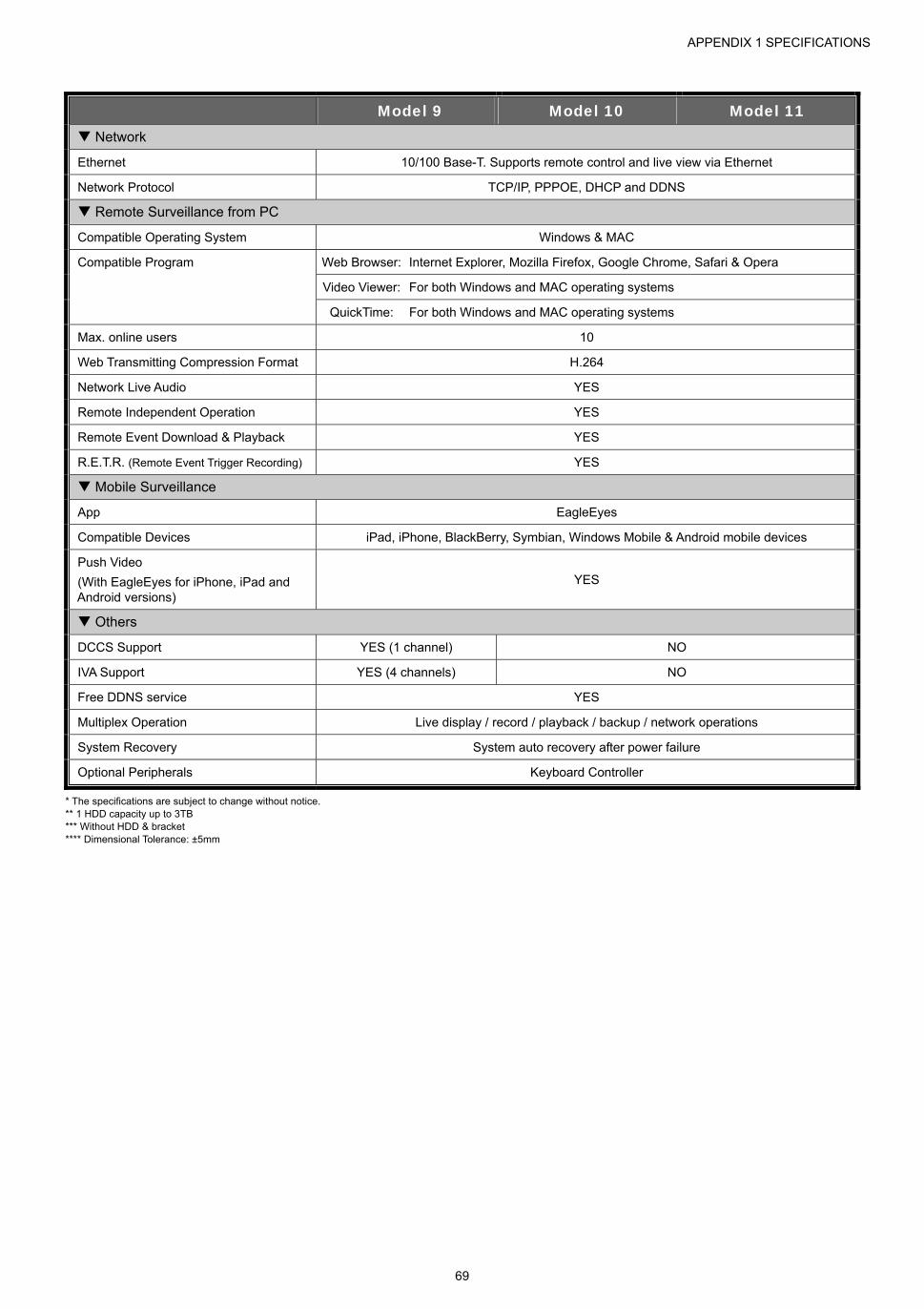
APPENDIX 1 SPECIFICATIONS
69
Model 9 Model 10 Model 11 Network
Ethernet 10/100 Base-T. Supports remote control and live view via Ethernet
Network Protocol TCP/IP, PPPOE, DHCP and DDNS
Remote Surveillance from PC
Compatible Operating System Windows & MAC
Compatible Program Web Browser: Internet Explorer, Mozilla Firefox, Google Chrome, Safari & Opera
Video Viewer: For both Windows and MAC operating systems
QuickTime: For both Windows and MAC operating systems
Max. online users 10
Web Transmitting Compression Format H.264
Network Live Audio YES
Remote Independent Operation YES
Remote Event Download & Playback YES
R.E.T.R. (Remote Event Trigger Recording) YES
Mobile Surveillance
App EagleEyes
Compatible Devices iPad, iPhone, BlackBerry, Symbian, Windows Mobile & Android mobile devices
Push Video
(With EagleEyes for iPhone, iPad and Android versions)
YES
Others
DCCS Support YES (1 channel) NO
IVA Support YES (4 channels) NO
Free DDNS service YES
Multiplex Operation Live display / record / playback / backup / network operations
System Recovery System auto recovery after power failure
Optional Peripherals Keyboard Controller
* The specifications are subject to change without notice. ** 1 HDD capacity up to 3TB *** Without HDD & bracket **** Dimensional Tolerance: ±5mm

APPENDIX 1 SPECIFICATIONS
70
8CH Models
Model 12 Model 13 Video
Video System NTSC / PAL (auto detection)
Video Compression Format H.264
Video Input 8 channels (Composite video signal 1 Vp-p 75Ω BNC)
Video Loop Output NO
Video Output BNC NO
YES
(Call monitor for sequence display)
VGA YES (Full HD display)
HDMI YES (Full HD display)
Dual Video Output YES
Record & Backup
Maximum Recording Rate 960H 960 x 480 pixels with 180 IPS <NTSC> / 960 x 576 pixels with 150 IPS <PAL>
Frame 704×480 pixels with 240 IPS <NTSC> / 704×576 pixels with 200 IPS <PAL>
Field 704x240 pixels with 240 IPS <NTSC> / 704×288 pixels with 200 IPS <PAL>
CIF 352×240 pixels with 240 IPS <NTSC> / 352×288 pixels with 200 IPS <PAL>
Image Resolution 960H / Frame / Field / CIF
Recording Mode Manual / Timer / Motion / Alarm / Remote
Pre-alarm Recording YES
Quick Search Time / Motion / Alarm search mode
Backup Device USB 2.0 flash drive / Network
Audio
Audio Input 4 audio inputs
Audio Output 1 audio output (Mono)
General
Hard Disk Storage** 2 SATA HDDs 1 SATA HDD
SATA Interface YES
eSATA Interface YES (For external disk array connection)
Image Quality Setting SUPER BEST / BEST / HIGH / NORMAL
USB Mouse Control YES
Motion Detection Area 16 × 12 grids per channel
Motion Detection Sensitivity 3 adjustable parameters for accurate detection
Event Notification Push Video / FTP / E-Mail
Picture Zoom 2X digital zoom
PTZ Control YES
Alarm I/O 8 inputs (2 inputs for Push Video), 1 output
IR Remote Control YES (IR receiver built-in)
Key Lock (Password Protection) YES
User Level 4 user levels for different access privilege
Video Loss Detection YES
Camera Title Supports up to 12 letters
General
Daylight Saving YES
Power Source (±10%) DC19 V /2.1A
Power Consumption (±10%)*** 11W 10.5W
Operating Temperature 10 ~ 40 (50~104)
Dimensions (mm)**** 430(W) x 65(H) x 338(D) 343(W) x 59(H) x 223(D)
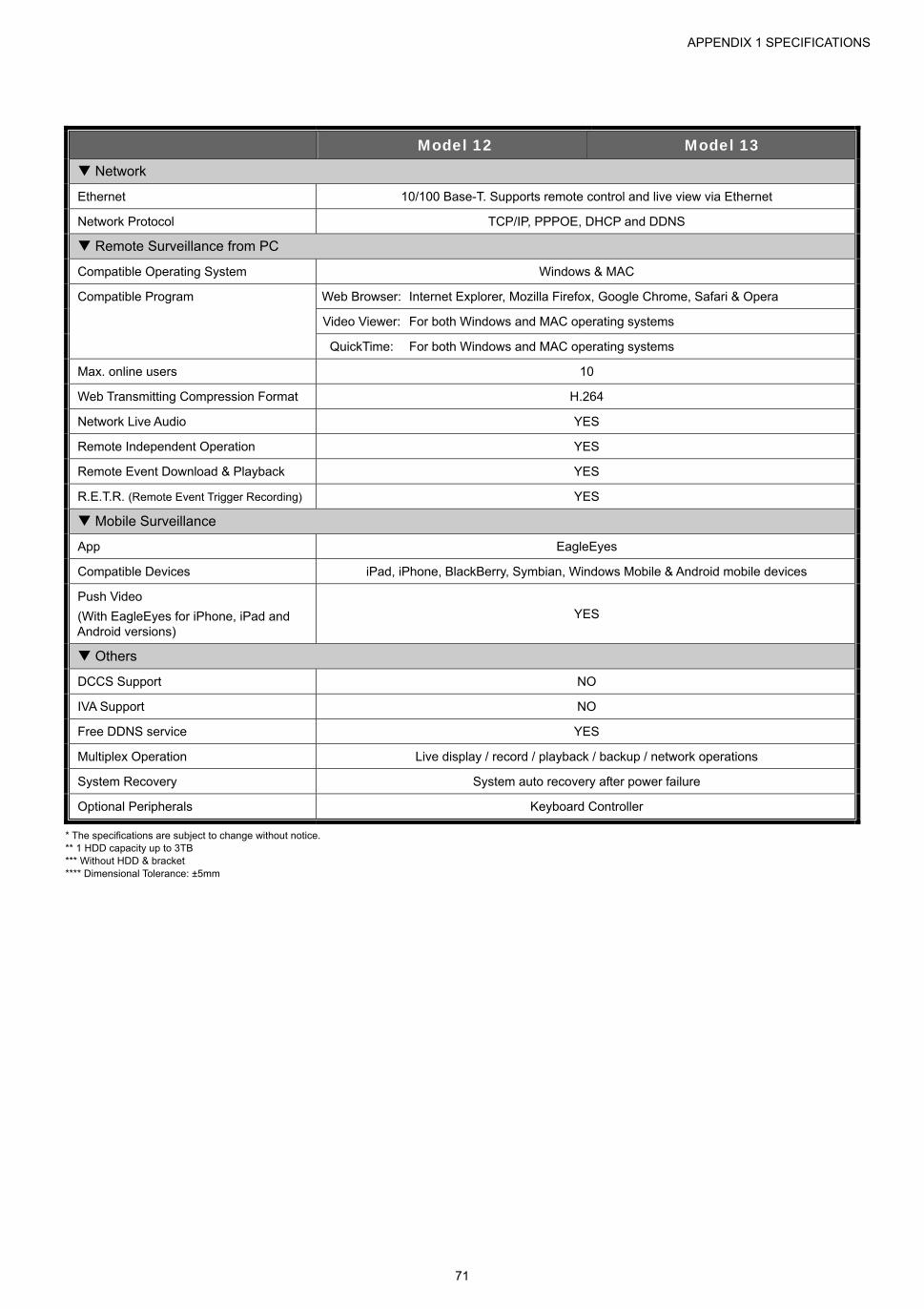
APPENDIX 1 SPECIFICATIONS
71
Model 12 Model 13 Network
Ethernet 10/100 Base-T. Supports remote control and live view via Ethernet
Network Protocol TCP/IP, PPPOE, DHCP and DDNS
Remote Surveillance from PC
Compatible Operating System Windows & MAC
Compatible Program Web Browser: Internet Explorer, Mozilla Firefox, Google Chrome, Safari & Opera
Video Viewer: For both Windows and MAC operating systems
QuickTime: For both Windows and MAC operating systems
Max. online users 10
Web Transmitting Compression Format H.264
Network Live Audio YES
Remote Independent Operation YES
Remote Event Download & Playback YES
R.E.T.R. (Remote Event Trigger Recording) YES
Mobile Surveillance
App EagleEyes
Compatible Devices iPad, iPhone, BlackBerry, Symbian, Windows Mobile & Android mobile devices
Push Video
(With EagleEyes for iPhone, iPad and Android versions)
YES
Others
DCCS Support NO
IVA Support NO
Free DDNS service YES
Multiplex Operation Live display / record / playback / backup / network operations
System Recovery System auto recovery after power failure
Optional Peripherals Keyboard Controller
* The specifications are subject to change without notice. ** 1 HDD capacity up to 3TB *** Without HDD & bracket **** Dimensional Tolerance: ±5mm

APPENDIX 1 SPECIFICATIONS
72
4CH Models
Model 13 Model 14 Model 15 Video
Video System NTSC / PAL (auto detection)
Video Compression Format H.264
Video Input 4 channels (Composite video signal 1 Vp-p 75Ω BNC)
Video Output BNC
YES
(Call monitor for sequence display)
NO
VGA YES (Full HD display)
HDMI YES (Full HD display)
Dual Video Output YES
Record & Backup
Maximum Recording Rate 960H 960 x 480 pixels with 90 IPS <NTSC> / 960 x 576 pixels with 75 IPS <PAL>
Frame 704×480 pixels with 120 IPS <NTSC> / 704×576 pixels with 100 IPS <PAL>
Field 704x240 pixels with 120 IPS <NTSC> / 704×288 pixels with 100 IPS <PAL>
CIF 352×240 pixels with 120 IPS <NTSC> / 352×288 pixels with 100 IPS <PAL>
Image Resolution 960H / Frame / Field / CIF
Recording Mode Manual / Timer / Motion / Alarm / Remote
Pre-alarm Recording YES
Quick Search Time / Motion / Alarm search mode
Backup Device USB 2.0 flash drive / Network
Audio
Audio Input 4 audio inputs
Audio Output 1 audio output (Mono)
General
Hard Disk Storage** 1 SATA HDD
SATA Interface YES
eSATA Interface YES (For external disk array connection) NO
Image Quality Setting SUPER BEST / BEST / HIGH / NORMAL
USB Mouse Control YES
Motion Detection Area 16 × 12 grids per channel
Motion Detection Sensitivity 3 adjustable parameters for accurate detection
Event Notification Push Video / FTP / E-Mail FTP / E-Mail
Picture Zoom 2X digital zoom
PTZ Control YES
Alarm I/O 4 inputs (1 input for Push Video), 1 output 4 inputs, 1 output
IR Remote Control YES (IR receiver built-in)
Key Lock (Password Protection) YES
User Level 4 user levels for different access privilege
Video Loss Detection YES
Camera Title Supports up to 12 letters
General
Daylight Saving YES
Power Source (±10%) DC19V / 2.1A DC12V / 3A
Power Consumption (±10%)*** 6W 5W 5W
Operating Temperature 10 ~ 40 (50~104)
Dimensions (mm)**** 375(W) × 61(H) × 281(D)
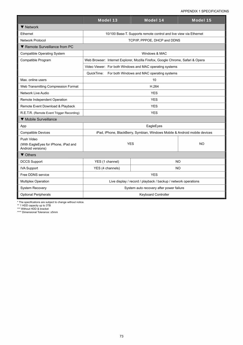
APPENDIX 1 SPECIFICATIONS
73
Model 13 Model 14 Model 15 Network
Ethernet 10/100 Base-T. Supports remote control and live view via Ethernet
Network Protocol TCP/IP, PPPOE, DHCP and DDNS
Remote Surveillance from PC
Compatible Operating System Windows & MAC
Compatible Program Web Browser: Internet Explorer, Mozilla Firefox, Google Chrome, Safari & Opera
Video Viewer: For both Windows and MAC operating systems
QuickTime: For both Windows and MAC operating systems
Max. online users 10
Web Transmitting Compression Format H.264
Network Live Audio YES
Remote Independent Operation YES
Remote Event Download & Playback YES
R.E.T.R. (Remote Event Trigger Recording) YES
Mobile Surveillance
App EagleEyes
Compatible Devices iPad, iPhone, BlackBerry, Symbian, Windows Mobile & Android mobile devices
Push Video
(With EagleEyes for iPhone, iPad and Android versions)
YES NO
Others
DCCS Support YES (1 channel) NO
IVA Support YES (4 channels) NO
Free DDNS service YES
Multiplex Operation Live display / record / playback / backup / network operations
System Recovery System auto recovery after power failure
Optional Peripherals Keyboard Controller
* The specifications are subject to change without notice. ** 1 HDD capacity up to 3TB *** Without HDD & bracket **** Dimensional Tolerance: ±5mm

APPENDIX 1 SPECIFICATIONS
74
4CH Models
Model 16 Model 17 Video
Video System NTSC / PAL (auto detection)
Video Compression Format H.264
Video Input 4 channels (Composite video signal 1 Vp-p 75Ω BNC)
Video Output BNC NO
VGA YES (Full HD display)
HDMI YES (Full HD display)
Dual Video Output YES
Record & Backup
Maximum Recording Rate 960H 960 x 480 pixels with 90 IPS <NTSC> / 960 x 576 pixels with 75 IPS <PAL>
Frame 704×480 pixels with 120 IPS <NTSC> / 704×576 pixels with 100 IPS <PAL>
Field 704x240 pixels with 120 IPS <NTSC> / 704×288 pixels with 100 IPS <PAL>
CIF 352×240 pixels with 120 IPS <NTSC> / 352×288 pixels with 100 IPS <PAL>
Image Resolution 960H / Frame / Field / CIF
Recording Mode Manual / Timer / Motion / Alarm / Remote
Pre-alarm Recording YES
Quick Search Time / Motion / Alarm search mode
Backup Device USB 2.0 flash drive / Network
Audio
Audio Input 4 audio inputs
Audio Output 1 audio output (Mono)
General
Hard Disk Storage** 1 SATA HDD
SATA Interface YES
eSATA Interface YES (For external disk array connection) NO
Image Quality Setting SUPER BEST / BEST / HIGH / NORMAL
USB Mouse Control YES
Motion Detection Area 16 × 12 grids per channel
Motion Detection Sensitivity 3 adjustable parameters for accurate detection
Event Notification Push Video / FTP / E-Mail FTP / E-Mail
Picture Zoom 2X digital zoom
PTZ Control YES
Alarm I/O 4 inputs (1 input for Push Video), 1 output 4 inputs, 1 output
IR Remote Control YES (IR receiver built-in)
Key Lock (Password Protection) YES
User Level 4 user levels for different access privilege
Video Loss Detection YES
Camera Title Supports up to 12 letters
General
Daylight Saving YES
Power Source (±10%) DC19V / 2.1A DC12V / 3A
Power Consumption (±10%)*** 5W 5W
Operating Temperature 10 ~ 40 (50~104)
Dimensions (mm)**** 343(W) x 59(H) x 223(D)

APPENDIX 1 SPECIFICATIONS
75
Model 16 Model 17 Network
Ethernet 10/100 Base-T. Supports remote control and live view via Ethernet
Network Protocol TCP/IP, PPPOE, DHCP and DDNS
Remote Surveillance from PC
Compatible Operating System Windows & MAC
Compatible Program Web Browser: Internet Explorer, Mozilla Firefox, Google Chrome, Safari & Opera
Video Viewer: For both Windows and MAC operating systems
QuickTime: For both Windows and MAC operating systems
Max. online users 10
Web Transmitting Compression Format H.264
Network Live Audio YES
Remote Independent Operation YES
Remote Event Download & Playback YES
R.E.T.R. (Remote Event Trigger Recording) YES
Mobile Surveillance
App EagleEyes
Compatible Devices iPad, iPhone, BlackBerry, Symbian, Windows Mobile & Android mobile devices
Push Video
(With EagleEyes for iPhone, iPad and Android versions)
YES NO
Others
DCCS Support NO
IVA Support NO
Free DDNS service YES
Multiplex Operation Live display / record / playback / backup / network operations
System Recovery System auto recovery after power failure
Optional Peripherals Keyboard Controller
* The specifications are subject to change without notice. ** 1 HDD capacity up to 3TB *** Without HDD & bracket **** Dimensional Tolerance: ±5mm
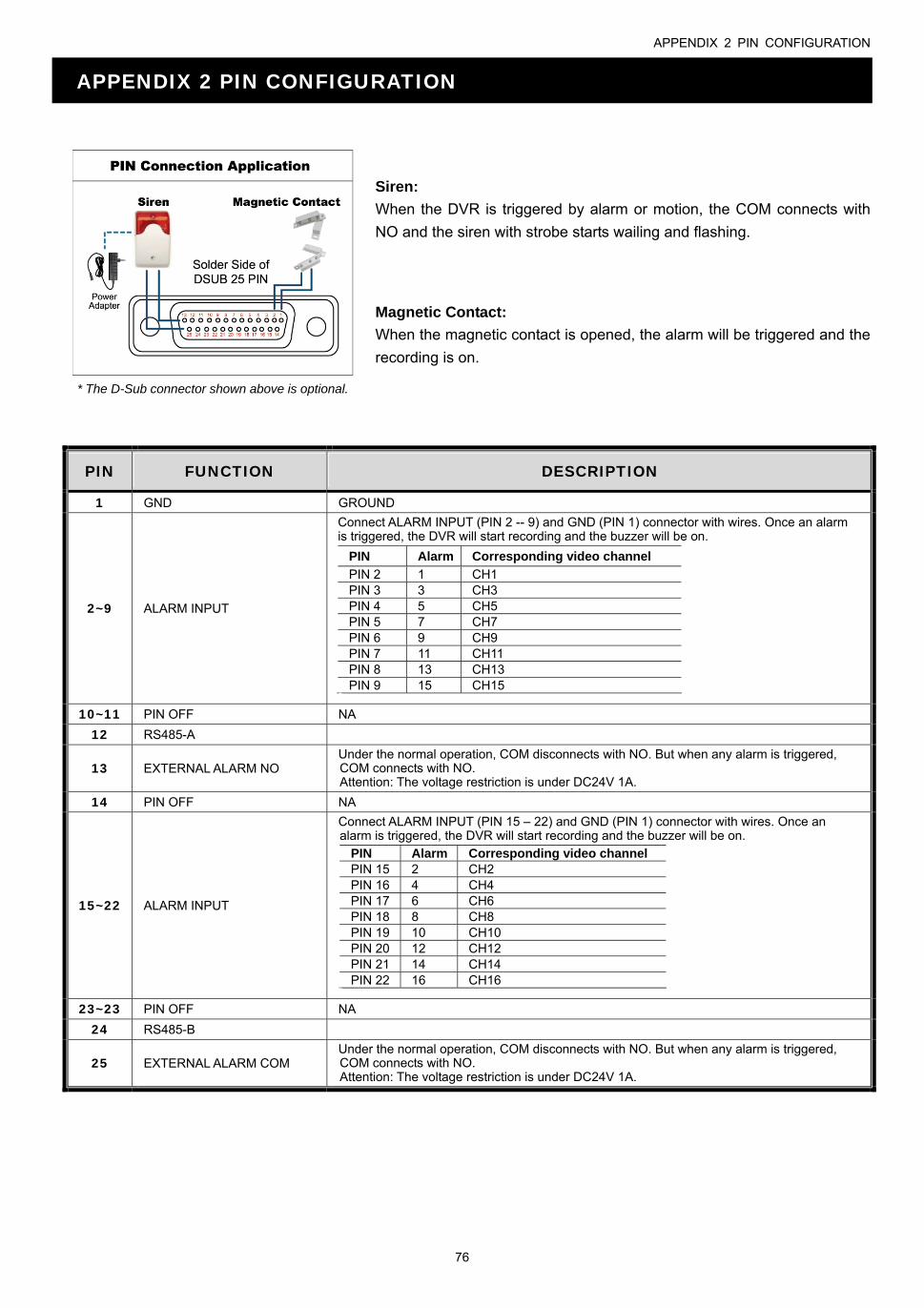
APPENDIX 2 PIN CONFIGURATION
76
APPENDIX 2 PIN CONFIGURATION
Siren:
When the DVR is triggered by alarm or motion, the COM connects with
NO and the siren with strobe starts wailing and flashing.
* The D-Sub connector shown above is optional.
Magnetic Contact:
When the magnetic contact is opened, the alarm will be triggered and the
recording is on.
PIN FUNCTION DESCRIPTION
1 GND GROUND
2~9 ALARM INPUT
Connect ALARM INPUT (PIN 2 -- 9) and GND (PIN 1) connector with wires. Once an alarm is triggered, the DVR will start recording and the buzzer will be on.
PIN Alarm Corresponding video channel
PIN 2 1 CH1 PIN 3 3 CH3 PIN 4 5 CH5 PIN 5 7 CH7 PIN 6 9 CH9 PIN 7 11 CH11 PIN 8 13 CH13 PIN 9 15 CH15
* 10~11 PIN OFF NA
12 RS485-A
13 EXTERNAL ALARM NO Under the normal operation, COM disconnects with NO. But when any alarm is triggered, COM connects with NO. Attention: The voltage restriction is under DC24V 1A.
14 PIN OFF NA
15~22 ALARM INPUT
Connect ALARM INPUT (PIN 15 – 22) and GND (PIN 1) connector with wires. Once an alarm is triggered, the DVR will start recording and the buzzer will be on.
PIN Alarm Corresponding video channel PIN 15 2 CH2 PIN 16 4 CH4 PIN 17 6 CH6 PIN 18 8 CH8 PIN 19 10 CH10 PIN 20 12 CH12 PIN 21 14 CH14 PIN 22 16 CH16
* 23~23 PIN OFF NA
24 RS485-B
25 EXTERNAL ALARM COM Under the normal operation, COM disconnects with NO. But when any alarm is triggered, COM connects with NO. Attention: The voltage restriction is under DC24V 1A.

APPENDIX 3 PUSH VIDEO CONFIGURATION
77
APPENDIX 3 PUSH VIDEO CONFIGURATION
Note: Available only when your DVR supports Push Video.
A3.1 PIN Connection
This DVR supports sending instant event notifications to your mobile devices, such as iPhone, iPad and Android
mobile devices, for an alarm event (Push Video). However, only certain alarm-in pins support this function.
There are two methods to connect alarm sensors for Push Video to take efforts: via PUSH VIDEO alarm-in
terminal and via external I/O port.
PUSH VIDEO alarm-in terminal
A PUSH VIDEO alarm-in terminal is provided on the DVR rear panel, similar as the picture below, to help you
quickly find and connect to the pins which support Push Video.
Note: Below takes 16CH models as an example. For 8CH and 4CH models, the alarm-in terminal should be 2 (for 8CH models) and 1 (for 4CH models).
Alarm Corresponding video channel
Alarm 1 CH1
Alarm 2 CH2
Alarm 3 CH3
Alarm 4 CH4
GNDAlarm 1 ~ 4
External I/O port
Check the table below to know which pin for alarm devices supports Push Video and its corresponding video
channel.
PIN Corresponding video channel
16CH Model PIN2 CH1
PIN15 CH2
PIN3 CH3
PIN16 CH4
8CH Model PIN2 CH1
PIN15 CH2
4CH Model PIN1 CH1

APPENDIX 3 PUSH VIDEO CONFIGURATION
78
Alarm sensor connection
Connect the alarm sensor, such as magnetic contacts, to the PUSH VIDEO alarm-in terminal or I/O pin which
supports Push Video on the DVR rear panel.
A3.2 Configuration
Before configuring Push Video, make sure:
1. The DVR system is set up as described in “2. CONNECTION AND SETUP” at page 4.
2. The DVR is connected to Internet.
3. You’ve installed the app, EagleEyes, on your iPhone, iPad or Android mobile devices. For details, please refer to “APPENDIX 4 MOBILE SURVEILLANCE VIA EAGLEEYES” at page 80.
Step1: Right click to show the main menu.
Go to (ADVANCED CONFIG.) "NOTIFY” to enable “GUARD” to “ON”, and configure your alarm sensor type (N.C. or N.O.).
ADVANCED CONFIG
CANERA PUSH VIDEO PUSH STATUS MESSAGE MAIL VIDEO MAIL DETECTION GUARD ON ALERT CH01 ALARM OFF / INTERNAL ALARM CH1 NETWORK CH02 ALARM OFF CH2 DISPLAY CH03 ALARM N.O. office RECORD CH04 ALARM OFF CH4 DEVICES DCCS IVS NOTIFY
EXIT
Step2: Open EagleEyes, and add this DVR to the EagleEyes address book.
Note: For more details about EagleEyes operation, please visit www.eagleeyescctv.com.
Step3: Enable Push Video as described below, and try to trigger your sensor to see if you can receive Push Video
successfully.
APPENDIX 3 PUSH VIDEO CONFIGURATION
79

APPENDIX 4 MOBILE SURVEILLANCE VIA EAGLEEYES
80
APPENDIX 4 MOBILE SURVEILLANCE VIA EAGLEEYES
EagleEyes is a mobile phone program used with our surveillance system for remote surveillance. It has several
advantages:
It’s free (Except EagleEyes Plus for iPhone, EagleEyes Plus+ for Android, and EagleEyesHD Plus for iPad).
It’s compatible with several popular mobile platforms, such as iPhone, iPad, BlackBerry and Android.
It’s easy to download, install and configure. For more details about configuring and operating this program, please
visit our official website www.eagleeyescctv.com.
A4.1 Prerequisites
Before installing EagleEyes to your mobile phone for remote surveillance, make sure you have checked the
following:
Your mobile platform is iPhone, iPad, BlackBerry and Android.
Mobile Internet services are subscribed and available to use for your mobile phone.
Note: You might be charged for Internet access via wireless or 3G networks. For the Internet access rate details, please check with your local network operator or service provider.
You have noted down the IP address, port number, user name and password used to access your network
camera from Internet.
A4.2 Where to download
Connect to www.eagleeyescctv.com from your mobile device, and sign in.
Note: Please DO NOT try to download EagleEyes from your computer.
Select the mobile platform you’re using to enter its individual download page.
Note: You can also find EagleEyes on “App StoreSM” / “Google Play™” from your iOS® / Android™ mobile devices.
When the download is completed, EagleEyes will be installed automatically to the location where all applications
are saved in your phone by default, or where you specify.

APPENDIX 5 SET PUSH VIDEO
81
APPENDIX 5 SET PUSH VIDEO
Note: Push Video is available only for selected models. Please check the product specifications or check with your installer for more details.
This DVR series supports instant event notifications to your iPhone / iPad / Android mobile device with our self-developed program, “EagleEyes”, installed. When a man is detected by a human detection camera or the external alarm device, the DVR will immediately receive alarm signals and send to your iPhone / iPad / Android mobile device.
Note: iPhone, iPad and Android are the trademarks or registered trademarks of their respective holders.
A5.1 Prerequisite
Before setting this function, make sure you have checked the following:
You have an iPhone® / iPad® / Android™ mobile device with our self-developed program, “EagleEyes”, installed. For
details, please refer to the previous chapter.
A human detection camera is connected to CH1 (for models which support DCCS), or an external alarm device is
connected to “PUSH VIDEO Alarm In” on the rear panel. Make sure a camera is also connected to record for alarm
occurrences. To know which video channel corresponds to which alarm pin, please refer to “APPENDIX 3 PUSH VIDEO
CONFIGURATION” at page 77.
The event record function of your DVR is not disabled.
The motion detection function of your DVR is not disabled.
Your DVR is connected to Internet. For details, please refer to
http://www.surveillance-download.com/user/CMS.pdf.
A5.2 Enable Push Video
A5.2.1 From iOS® Mobile Device (iPhone® / iPad®)
Step1: In the iPhone® / iPad® main menu, select “Settings” “Notifications”. Select “EagleEyes”, and make sure
"Notification Center” is set to “ON”.

APPENDIX 5 SET PUSH VIDEO
82
Step2: Open “EagleEyes”, and switch the Push Video button to “ON”. You’ll receive the message indicating that
Push Video is on.
Step3: Return to the main menu of your iPhone® / iPad®. You’ll receive event notifications when there’s an alarm
event. Select “Launch” (or “View” base on your iOS® version) to immediately play the recorded clip.
A5.2.2 From Android™ Mobile Device
In the address book, switch “Guard” from “OFF” to “ON”.
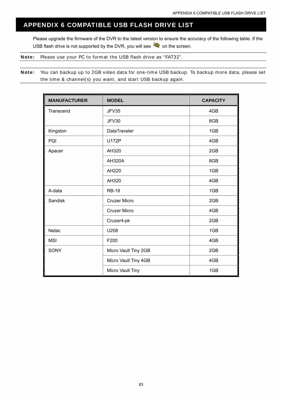
APPENDIX 6 COMPATIBLE USB FLASH DRIVE LIST
83
APPENDIX 6 COMPATIBLE USB FLASH DRIVE LIST
Please upgrade the firmware of the DVR to the latest version to ensure the accuracy of the following table. If the
USB flash drive is not supported by the DVR, you will see on the screen.
Note: Please use your PC to format the USB flash drive as “FAT32”.
Note: You can backup up to 2GB video data for one-time USB backup. To backup more data, please set the time & channel(s) you want, and start USB backup again.
MANUFACTURER MODEL CAPACITY
Transcend JFV35 4GB
JFV30 8GB
Kingston DataTraveler 1GB
PQI U172P 4GB
Apacer AH320 2GB
AH320A 8GB
AH220 1GB
AH320 4GB
A-data RB-18 1GB
Sandisk Cruzer Micro 2GB
Cruzer Micro 4GB
Cruzer4-pk 2GB
Netac U208 1GB
MSI F200 4GB
SONY Micro Vault Tiny 2GB 2GB
Micro Vault Tiny 4GB 4GB
Micro Vault Tiny 1GB
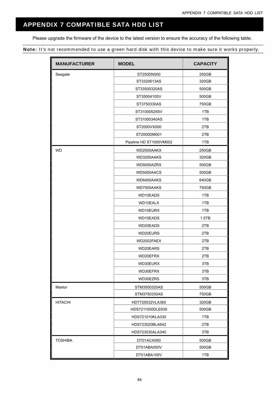
APPENDIX 7 COMPATIBLE SATA HDD LIST
84
APPENDIX 7 COMPATIBLE SATA HDD LIST
Please upgrade the firmware of the device to the latest version to ensure the accuracy of the following table.
Note: It’s not recommended to use a green hard disk with this device to make sure it works properly.
MANUFACTURER MODEL CAPACITY
Seagate ST250DN000 250GB
ST3320613AS 320GB
ST33500320AS 500GB
ST3500410SV 500GB
ST3750330AS 750GB
ST31000525SV 1TB
ST31000340AS 1TB
ST2000VX000 2TB
ST2000DM001 2TB
Pipeline HD ST1000VM002 1TB
WD WD2500AAKX 250GB
WD3200AAKS 320GB
WD5000AZRX 500GB
WD5000AACS 500GB
WD6400AAKS 640GB
WD7500AAKS 750GB
WD10EADS 1TB
WD10EALX 1TB
WD10EURX 1TB
WD15EADS 1.5TB
WD20EADS 2TB
WD20EURS 2TB
WD2002FAEX 2TB
WD20EARS 2TB
WD20EFRX 2TB
WD30EURX 3TB
WD30EFRX 3TB
WD30EZRS 3TB
Maxtor STM3500320AS 500GB
STM3750330AS 750GB
HITACHI HDT725032VLA360 320GB
HDS7211050DLE630 500GB
HDS721010KLA330 1TB
HDS723020BLA642 2TB
HDS723030ALA340 3TB
TOSHIBA DT01ACA050 500GB
DT01ABA050V 500GB
DT01ABA100V 1TB

APPENDIX 8 MAIN MENU STRUCTURE
85
APPENDIX 8 MAIN MENU STRUCTURE
QUICK START GENERAL CHANNEL TITLE EVENT STATUS PLAYBACK STATUS DISPLAY DATE DISPLAY MOUSE SENSITIVITY RECORD CONFIG
TIME SETUP DATE
TIME
NTP SERVER
FORMAT
SYNC PERIOD
GMT
DAYLIGHT
SYSTEM ACCOUNT TOOLS LANGUAGE UPGRADE NETWORK UPGRADE BACKUP CONFIG
RESTORE CONFIG
SYSTEM INFO BAUD RATE HOST ID R.E.T.R. AUTO KEY LOCK(S) CLEAR HDD RESET DEFAULT REMOTE CONTROL ID SERIAL TYPE VIDEO FORMAT VERSION BACKUP DATA BACKUP LOG
REGULAR REPORT
EVENT INFORMATION QUICK SEARCH
EVENT SEARCH
HDD INFO
EVENT LOG
ADVANCED CONFIG CAMERA BRIGHTNESS CONTRAST SATURATION HUE COV. REC TIME STAMP DISPLAY CHANNEL TITLE
DETECTION LS SS TS MOTION ALARM AREA
ALERT EXT. ALERT INT. BUZZER KEY BUZZER VLOSS BUZZER MOTION BUZZER ALARM BUZZER HDD BUZZER ALARM DURATION (SEC) HDD NEARLY FULL (GB)
HDD OVERHEAT ALERT (°C)
NETWORK WAN FTP E-MAIL
DDNS
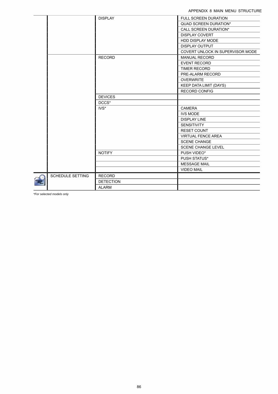
APPENDIX 8 MAIN MENU STRUCTURE
86
DISPLAY FULL SCREEN DURATION
QUAD SCREEN DURATION*
CALL SCREEN DURATION*
DISPLAY COVERT
HDD DISPLAY MODE
DISPLAY OUTPUT
COVERT UNLOCK IN SUPERVISOR MODE
RECORD MANUAL RECORD
EVENT RECORD
TIMER RECORD
PRE-ALARM RECORD
OVERWRITE
KEEP DATA LIMIT (DAYS)
RECORD CONFIG
DEVICES
DCCS*
IVS* CAMERA
IVS MODE
DISPLAY LINE
SENSITIVITY
RESET COUNT
VIRTUAL FENCE AREA
SCENE CHANGE
SCENE CHANGE LEVEL
NOTIFY PUSH VIDEO*
PUSH STATUS*
MESSAGE MAIL
VIDEO MAIL
SCHEDULE SETTING RECORD
DETECTION
ALARM
*For selected models only

APPENDIX 9 DVR BATTERY REPLACEMENT
87
APPENDIX 9 DVR BATTERY REPLACEMENT
DVR time reset after power failure, for example, caused by a power outage, will cause the disorder of the recorded data,
and users may have problems in searching the event clip they want. To keep the DVR time from resetting, a
non-chargeable lithium battery, CR2032, is installed in the DVR.
However, the DVR time might still get reset when the DVR battery is low or even running out of power. If so, please
replace the DVR battery, CR2032, right away as instructed below.
How to replace CR2032
Note: The lithium battery, CR2032, is a non-chargeable battery, and should be purchased separately. Please replace only with the same or equivalent type battery in case of danger.
Step1: Stop all DVR recording immediately to prevent the disorder of the recorded data. Then, back up the
recorded data if necessary.
Step2: Power off the DVR, and disconnect the DVR power.
Step3: Remove the DVR cover, and find the battery on the mainboard.
Step4: Push the release as indicated below to remove the battery.
Step5: Get a new battery with the side of “CR2032” facing up, and install it to the mainboard.
Step6: Replace the DVR cover and connect to power.
Step7: Set DVR date & time, and resume recording. For details, please refer to “2.5 Date and Time Setting” at page
9, and “5.4.6 RECORD” at page 38.
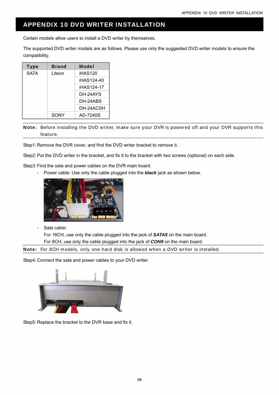
APPENDIX 10 DVD WRITER INSTALLATION
88
APPENDIX 10 DVD WRITER INSTALLATION
Certain models allow users to install a DVD writer by themselves.
The supported DVD writer models are as follows. Please use only the suggested DVD writer models to ensure the
compatibility.
Type Brand Model SATA Liteon iHAS120
iHAS124-40
iHAS124-17
DH-24AYS
DH-24ABS
DH-24ACSH
SONY AD-7240S
Note: Before installing the DVD writer, make sure your DVR is powered off and your DVR supports this feature.
Step1: Remove the DVR cover, and find the DVD writer bracket to remove it.
Step2: Put the DVD writer in the bracket, and fix it to the bracket with two screws (optional) on each side.
Step3: Find the sata and power cables on the DVR main board.
- Power cable: Use only the cable plugged into the black jack as shown below.
- Sata cable:
For 16CH, use only the cable plugged into the jack of SATA5 on the main board.
For 8CH, use only the cable plugged into the jack of CON9 on the main board.
Note: For 8CH models, only one hard disk is allowed when a DVD writer is installed.
Step4: Connect the sata and power cables to your DVD writer.
Step5: Replace the bracket to the DVR base and fix it.