full body adjustment using iterative inverse …
TRANSCRIPT

Journal of Mobile Multimedia, Vol. 10, No. 3&4 (2014) 309–326c© Rinton Press
FULL BODY ADJUSTMENT USING ITERATIVE INVERSE KINEMATIC
AND BODY PARTS CORRELATION
AHLEM BENTRAH ABDELHAMID DJEFFAL MC BABAHENINI
LESIA Laboratory, Biskra University
Biskra 07000, Algeriaahlem [email protected], abdelhamid [email protected], [email protected]
CHRISTOPHE GILLET PHILIPPE PUDLO ABDELMALIK TALEB-AHMED
LAMIH Laboratory, Valenciennes University
Valenciennes 59300, France
{christophe.gillet, philippe.pudlo, abdelmalik.taleb-ahmed} @univ-valenciennes.fr
In this paper, we present an iterative inverse kinematic method that adjust 3D human full
body pose in real time to achieve new constraints. The input data for the adjustments arethe starting posture and the desired end effectors positions -constraints-. The principal
idea of our method is to divide the full-body into groups and apply inverse kinematic
based on conformal algebra to each group in specific order, our proposed method involvecorrelation of body parts. In the first part of the paper we explain the used inverse
kinematic when handle with one and multiple constraints simultaneously and in the
case of the collision induced by the joints with the objects of the environment. Thesecond part focuses on the adjustment algorithm of the full body using the inverse
kinematic described above. Comparison is made between the used inverse kinematic(IK)
and another inverse kinematic that have the same principle. In the case of multiple taskssimultaneously, our inverse kinematic gives results without conflict. With presence of
obstacles, our IK allows to avoid collisions too. Preliminary results of the adjustmentmethod show that it generates new realistic poses that respect quickly new constraints.
The tests made on our adjustment method show that it resolves the motion retargeting
problem.
Keywords: Animation, Inverse kinematic, Geometric algebra, Virtual humanoid
1 Introduction
In many fields such as robotics and animation, there is often a need to control articulated
structures in complex conditions. In the animation case, the control may involve posing
the character body or some kinematic chain of the character to respect new constraints.
Constraints may be defined as end effectors targets or goal positions. In this paper, we refer
to reaching the goal position by task.
Character body is represented as series of different poses of rigid articulated chain, con-
sisting of set of segments connected by joints. The joints correspond to articulations such as
elbow, wrist, sterno-clavicular while the segments correspond to the body limbs such as the
upper arms, forearms... Each joint have one to three degrees of freedom (DOF) that represent
the rotation angle of the joint relative to its joint parent, the character body root is generally
in the pelvis. The root position/orientation and the joint rotation represent character pose
configuration. To generate new pose with known goal position where the new goal position
309
310 Full Body Adjustment Using Iterative Inverse Kinematic and Body Parts Correlation
may be the desired end-effector position or any other desired joint position. Inverse kinemat-
ics (IK) is one of the most important used techniques in which methods tend to compute the
joints angles in the aim of moving the end effectors as close as possible to the desired position.
1.1 Motivation
The focus of this research is aimed to moving away from recent character pose adjustment
using the data-driven inverse kinematics which need an important quantity of motions [17, 18],
towards an online method that can provide realistic character poses. This method can be used
in many field such as in the motion editing and the motion retargeting field to edit the motion
to fit some constraints or even in the robotic field to perform task. The main contribution of
this paper is to propose pose adjustment by:
(i) Dividing the character body into groups and apply IK to each group,
(ii) Using inverse kinematic method based on FABRIK method, our method differ to the
original FABRIK method in the following points :
(a) It minimizes the number of moved joints to reach targets,
(b) It uses the priority to avoid conflicts between tasks,
(c) It avoids obstacles while positioning end-effectors
(iii) Involve correlation of body parts.
The present paper is structured as follow: in the first section, we review related work
on the inverse kinematic, then we discuss IK methods, their advantages and drawbacks. In
the second section, we present an overview on the proposed method that allows to adjust
the full-body to new constraints. In third section, we present the inverse kinematic used
in the adjustment method for one and multiple constraints and in the case where there is
other objects in the environment. In the fourth section, we present our character model and
we introduce the steps of proposed adjustment method. In the last section we start with
comparison between our proposed inverse kinematic method and another method that have
the same principle (FABRIK), next we present preliminary results of our adjustment method
and an application of the proposed method to solve the motion retargeting problem.
2 Related work
The inverse kinematic problem is well studied. To handle simple kinematic chain that contains
a few degrees of freedom, the analytical methods are the best choice [5, 4]. These methods
are fast but they do not give solution in the complex articulated figures case. Numerical
methods based on Jacobian matrix [6, 2] are proposed to deal with complex articulated
figures. These methods tend to be computationally expensive. Moreover, they suffer from
singularities due to the matrix using. To overcome the high computational time, heuristic
method are proposed such as CCD (Cyclic Coordinate Descent) [3, 7] and triangulation [8].
The advantage of those methods is that they are computationally very fast. However they
do not support multiple tasks control. Kulpa in his work [9] tried to give solution to reach
multiple task simultaneously by dividing the whole body into groups and apply CCD method
[3] to each part separately. Another heuristic method called ”Forward and Backward Inverse
Kinematic” (FABRIK) proposed by Aristidou & Lasenby [1] to the hand modeling and traking,
it is based on geometric algebra to resolve the inverse kinematic problem. A comparison is

A. Bentrah, A. Djeffal, M. Babahenini, C. Gillet, P. Pudlo, and A. Taleb-Ahmed 311
made in [1] show that FABRIK method is fast than other inverse kinematic methods. The
FABRIK method can handle with angular limits. However, it presents conflicts when dealing
with multiple tasks. Beside, FABRIK is for unconstrained environments, hence it does not
give good results in the collisions case. Recently, an inverse kinematic methods that work in
the distance space are proposed [2]. A general problem of IK algorithms cited above is the
difficulty to ensure the naturalness of the generated pose. This is because natural human
motion involves correlation of body parts. Data driven IK systems have been presented as
in [17, 18], those methods are based on training data and create model, they can generate
natural pose but poses are highly related to the training data and require huge database.
Furthermore, Huang and Pelachaud, [20] they used a mass-spring model to adjust the joint
positions by minimising the force energy which is conserved in springs to solve the inverse
Kinematics problem from an energy transfer perspective.
The character control usually requires that we simultaneously apply multiple constraints
and manage multiple tasks [9, 1], which may lead to conflicts between tasks because some are
not achievable at the same time. An efficient inverse kinematic must have strategy to deal
with this problem. To treat this problem, some solutions are based on attributing weight
to each task to define their relative importance [10, 11] and solve the problem as a multi-
objective optimization where no task is achieved exactly but the sum of errors is minimized.
Other solution is based on ”task priority”. Priority based method as in [13] tend to sort the
tasks by order of priority, in order to satisfy the most important task first, the method in [13]
can deal with two tasks in the same time. Well known method in the priority task method is
PIK ”priority inverse kinematic” [12] where it can handle with many constraints.
The basic IK methods compute character poses in an obstacle free space. However most
environments are not obstacle free. This means that the inverse kinematics method should
give result without joint-obstacle collision. Many studies have been reported on the obstacle
avoidance problem. To deal with this problem two steps are needed, firstly ”collision de-
tection” where we detect when and where the joints collide with the obstacles, the second
step is ”collision response”. Our main focus is in the second step. Many studies have been
reported on the collision response problem in the animation and robotic domain. The Path
planning methods are mostly used in the animation [14, 15]. However, they are moreover
computationally expensive. Aside, the path planning method is not useful for the real time
motion control. In [19] are used for collision response for virtual human limbs, they treat
self-collision meaning that the arms and legs do not collide with other body parts of the
virtual character. In this method the authors treat the collision between the character arms
and legs. Nevertheless, this method is only useful when there are no other objects present
and self-collision is the only element to consider
3 Overview of the proposed method
Figure 1 shows an overview of the proposed method in which the character is divided into
five groups that correspond to the legs, trunk, arms and head. The groups are connected
by two joints, root and sterno-clavicular, this connection ensure the correlation or synergy
between the body parts, more detail to the subdividing step is explained the ”character
model” section . The subdividing of the body has the advantage to ease the adjustment,
while creating the synergy between the body parts ensure the realism of the adjustment

312 Full Body Adjustment Using Iterative Inverse Kinematic and Body Parts Correlation
result. To adjust pose to new constraints using our method, it should have as input the
initial character pose, the constrained joints and their desired positions. In the first step, the
root and the sterno clavicular configuration -position/orientation- are calculated based on the
desired positions. Then, the proposed inverse kinematic are applied to each group by order
to respect the constraints. In addition, to get more realistic pose, we may at each inverse
kinematic iteration set the joints biomechanical limits in case it is necessary, to respect the
biomecahnical limits of each joints, we will use the same principle as in [1].
Fig. 1. System overview
4 Iterative IK
Our inverse kinematic has the same principle as FABRIK [1]. Hence, it has two steps: Forward
and Backward. New joint position is calculated by keeping constant the length between jointiand jointi−1. Nevertheless, we propose algorithms to handle with environment obstacles and
conflict between tasks. The flowing sections represent the proposed idea.
4.1 Obstacle avoidance
Fig. 2. Obstacle avoidance processes

A. Bentrah, A. Djeffal, M. Babahenini, C. Gillet, P. Pudlo, and A. Taleb-Ahmed 313
It aim to ensure that the character joints do not collide with static or dynamic objects
(obstacles). static objects represent objects that do not move, while the dynamic objects
represent objects in motion. The strategy to avoid collisions must be integrated within the
IK algorithm. Our proposition is based on geometric algebra (GA) to calculate the joints
positions (figure 2). Using this algorithm, we keep the rapidity of our IK, which may be useful
in the interactive applications and fits with the iterative and local nature of the method used
for the inverse kinematic. Our proposed algorithm has two parts: detection and collision
response (figure 3). In the case where the character and the objects are in motion, we apply
the algorithm to each frame.
4.1.1 Collision detection
In this step we need to detect if the joint collide with the obstacle. There is many collision
detection methods, our detection algorithm uses Aligned Bounding Boxes (AABB). It consists
to encapsulate the environment objects with simple geometric forms as cubes and spheres,
then tests if a specific joint is in intersection with ABB or not. AAB simplifies the resolution
of intersection problem of complex forms.
4.1.2 Collision response
The basic inverse kinematic is position based local method. The new joint position depend on
the previous calculated joint position. Our proposition acts differently: the new joint position
does not depend only on the previous calculated joint position, but it depend also on the
obstacle position. In the inverse kinematic obstacle avoidance algorithm, we calculate the
new jointi position while keeping the distance D between jointi and jointi−1. We define posias this new position. If the jointi in posi(x0, y0, z0) collide with an object then we calculate
new position pos′
i(x, y, z) for this joint, else we keep this position and we calculate the next
joint position. pos′
i must respect two distances: D and dismax +4d. dismax is the distance
between the jointi and the bounding box edge and 4d represent security value (chosen equal
to 0.01). To respect the both distances, we used geometric algebra notions (GA). In this field,
to calculate the new joint position where we know the jointi and jointi−1 positions, can be
achieved by intersecting two spheres where the first sphere center is posi(x0, y0, z0) and its
radius is dis (dis = dismax +4d), the second sphere center is jointi−1 (x1, y1, z1) and it’s
radius is D. The two spheres intersection involves to solve the system of equation (1).
(x-x0)2 + (y − y0)2 + (z − z0)2 = dis2
(x-x1)2 + (y − y1)2 + (z − z1)2 = D2 (1)
The solution of the equation system (1) is a circle. As we need to get one point that will
be the new jointi without collision, we propose to fix the z coordinate, and because we have
the sum equal to D2 where dis2, (z − z0)or(z − z1) should not exceeds the radius. We used
equation Eq2 to fix z.
|z − z1| < Det|z − z0| < dis (2)
To find the new position pos′
i(x, y, z) of the jointi of the actual position posi(x0, y0, z0)
we must solve the following equation system:

314 Full Body Adjustment Using Iterative Inverse Kinematic and Body Parts Correlation
(x-x0)2 + (y − y0)2 + (z − z0)2 = dis2
(x-x1)2 + (y − y1)2 + (z − z1)2 = D2
|z − z1| < D et |Z − z0| < dis(3)
The proposed algorithm to find new joint position without collision with an obstacle is
summarized in the the following pseudo algorithm:
Obstacle avoidance algorithm
Input posi(x0, y0, z0 ), jointi−1(x1, y1, z1)
Objects list
Output new jointi position : pos′
i(x, y, z)
Check the intersection between jointi and the environment object
If there isn’t intersection
Do nothing and keep pos′
i(x, y, z) as jointi position
else
Calculate the distances between jointiand the bounding box corner (d1, d2, ..., dn)
Calculate dismax = max(d1, ..., dn)
Calculate z using equation (3)
Calculate x,y resolving (1) and (2)
Fig. 3. Obstacle avoidance using geometric algebra(GA): The elbow collide with an object (a),after applying the obstacle avoidance algorithm, the elbow don’t collide with the object
4.2 Multiple task
It is essential for an IK solver to be able to solve problems with multiple targets. However,
without good strategy this may lead to conflict between tasks. In our proposition, the char-
acter is subdivided into groups. Those groups are connected between them by sub-base: root
and streno-clavicular. Based on the work of Boulic [12] we propose to assign a priority to
each task. To get the position of the sub-joints two variants are proposed. We propose two
variants, because in some cases we have to verify the height priority task (foot on the ground)

A. Bentrah, A. Djeffal, M. Babahenini, C. Gillet, P. Pudlo, and A. Taleb-Ahmed 315
and in some other cases it is preferable to reach the highest priority task more then the lower
one. We use those variants to calculate the new sub-joints position.
4.2.1 Variant 1
To get the new joints position we apply the forward stage for each group, at the end of this
stage, many new sub-base positions are presented as the number of groups. The new sub-base
position is calculated using the following equation
newpos =
∑i=ni=1 posi × priorityi∑i=n
i=1 priorityi(4)
Where Posi is the sub-base position for the group i and Priorityi is the task priority of
the group i. Using the priority notation, the task that is more important will be achieved
before the lowest ones.
4.2.2 Variant 2
In this variant, we sort the tasks by the order of priority. We obtained numerous simple chains,
then we apply the previous algorithm for each simple chain, starting by the low priority chain
to the high one. Starting by the task with low priority ensure that the task that have the
highest priority will be reached much as possible.
5 Adjustment using inverse kinematic
5.1 Character model
The structure of our character model consists of rigid kinematic chain (cylinders) connected
by angular joints (figure 4).
Fig. 4. Character model:proposed hierarchy

316 Full Body Adjustment Using Iterative Inverse Kinematic and Body Parts Correlation
Fig. 5. Character representation :dividing the character onto groups
As in the work of Shin [16] where the character is subdivided into groups and analytic
inverse kinematic is applied to each group, we use almost the same principle. The figure 5
represents the character model. We decompose the humanoid in two parts and five groups.
The arms and trunk are linked by the ”streno-clavicular”, where the change in one arm config-
uration may affect change in the other arm and that may affect even the trunk configuration.
Beside, The legs and the trunk are linked by the ”root”,changing one leg configuration involve
change in the root configuration and the other leg. To more explain this correlation, suppose
we want to move the left foot to be in desired position, while this desired position is far from
the leg, to reach this task we may change in the root position, this changing affect another
member that is the other leg configuration. Re positioning/rotating the root involve change
in the all the groups configuration. This representation allow to ease the humanoid control.
After the subdividing we apply our inverse kinematic to each group. Using the inverse kine-
matic to subdividing groups make the adjustment method very fast. We apply just the joints
of the group concerned by the motion.
5.2 Full body adjustment
The main idea of our adjustment approach is that the adjustment is solved sequentially
using simple iterative IK based on geometric algebra on different parts of the body and in
specific order. No motion database is necessary. Based on the desired end-effectors, the
root and sterno-clavicular configurations are calculated. The trunk joints orientation are
calculated based on the new root and sterno-clavicular configurations. Finally, each of the
limbs configurations is determined based on the new clavicle position for the arms, the new
root position for the legs and the end-effectors positions with an iterative IK. Algorithm 1
summarizes the proposed method.

A. Bentrah, A. Djeffal, M. Babahenini, C. Gillet, P. Pudlo, and A. Taleb-Ahmed 317
Algorithm 1
input : starting character pose, desired end-effectors position
output : new character pose
1-Calculate the new root, sterno-clavicular position based on
the desired end-effectors positions
2-Trunk adjustment, using new sterno-clavicular position
3-Arms adjustment
4-Legs adjustment
end
5.2.1 Calculate the new root sterno-clavicular position
To reach an object, in real human motion it is preferable to solicit the trunk only when it
is impossible to achieve the target by moving just the arm. To achieve the natural pose, we
inspired our proposition from the real life. We first verify the contribution of the trunk and
the root in the arm or leg motion to satisfy the constraint, and then calculate the new trunk
configuration.
To test the contribution of the trunk in the motion, we calculate the distance D between
the sterno-clavicular and the target if its lower than the arm length, the sterno-clavicular and
the root keep their original positions 6.
In the opposite case, where the target is placed beyond arms length, the trunk chain is
integrated in the arm transport. In this case, the new sterno-clavicular position/orientation
Pos′
in order to get distance between target and this position equal to the arm length.
In some cases we cannot move the trunk in order to be the sterno-clavicular in pos′ (the
target is very far) one solution is to move the pelvis by error distance to be in pos′
pelvis.
The error distance in the pelvis position is calculated using the distance between the actual
position of the pelvis and the actual sterno-clavicular position, and the distance between the
actual sterno-clavicular position and Pos′.
In the case where there are two tasks to be achieved, user can choose between the two vari-
ants in order to calculate the sub-joint positions. In the case where both arms are constrained
the new trunk configuration is calculated considering the sterno-clavicular joint as the sub
joint between the two arms. The new sterno clavicular position is calculated by choosing one
variant from the variants described in section 4.2. If there is no variant chosen we calculate
the new sterno-clavicular position using equation (1). In the default case to calculate the
root position where there are constraints on the upper and lower body the root position is
calculated using variant two where the lower body constraint have the highest priority.

318 Full Body Adjustment Using Iterative Inverse Kinematic and Body Parts Correlation
Fig. 6. Reach target in simple chain. Figure a presents the initial arm configuration where wecalculate the arm length and the distance target-end effectors, in figure b we move just the arm
because the arm lenghth is lower then the distance between the target and the end-effectors
5.2.2 Root adjustment
Based on the sterno-clavicular and Ankles desired position we determine the new root position.
The ankles positions are given high priority. The new root position is calculated using variant
two in the sub-section 4.2. we choose this variant because the new root position must verify
strictly the ankles position.
5.2.3 Trunk adjustment
For the trunk adjustment, our inverse kinematic is applied on the trunk chain. The trunk
is constructed from five joints represent the most important spines. The root of the trunk
chain is the character body root and the end effectors are the sterno-clavicular. The aim of
this step is to find the new joints trunk position/orientation based on the sterno-clavicular
configuration.
Algortihm 3
Input :target position, initial trunk configuration
Output : trunk configuration
1- D1=|sterno-clavicular position-wrist position|
2-D=|sterno-clavicular position-object position|
3-If (D1<D) new sterno-clavicul position is calculated
Apply IK to find the new trunk configuration
End
In the case where both arms are constrained, the new trunk configuration is calculated
considering the sterno clavicular joint as the sub joint between the two arms. The new
sterno clavicular position is calculated by choosing one variant from the variants described in
section 4.2. If there is no variant chosen we calculate the new sterno-clavicular position using
equation (1). After getting the new position we apply IK to the trunk chain to get the new
trunk orientation.
5.2.4 Upper and lower body limbs adjustment
Now the configuration of the trunk and the root has been determined, we apply inverse kine-
matic to adjust the arms and the legs to their corresponding desired end effectors positions.

A. Bentrah, A. Djeffal, M. Babahenini, C. Gillet, P. Pudlo, and A. Taleb-Ahmed 319
For the arm limb, the root of the inverse kinematic is the sterno-clavicular position. While
for the legs, the root of the applied inverse kinematic is the pelvis.
6 Results
In the result section, we first compare our inverse kinematic with FABRIK method that have
the same principle, then we will give some preliminary results of our adjustment method and
the application of our adjustement method in the motion retargeting field. All the tests are
made in intel(R)Core(TM)i3-2330M CPU @ 2.20 GHZ and windows7 as operating system
machine.
6.1 Comparison of our IK to FABRIK
6.1.1 Priority inverse kinematic
Fig. 7. Multiple tasks case
In this subsection we implemented our priority inverse kinematic and FABRIK using matlabR
2011a as programming language. The Figure fig:result11 represents three chains connected
by sub-base with two end-effectors and two desired positions. In the character case, those
chains represent arms and trunk. This figure aims to represent how deal our inverse in the
presence of two target in the same time compared to FABRIK. Figure (7).a represents the
result when applying FABRIK to the chains, as shown there is conflict between tasks. When
320 Full Body Adjustment Using Iterative Inverse Kinematic and Body Parts Correlation
we apply our inverse kinematic to the chains in the figure (7).b the height priority target is
achieved without conflict.
The Variant1 result depends on the priority value of each task, thus the choice of the
priority value is very important, a wrong choice may achieve the high priority task but in
high computational time. While in the second variant the result depends only on the high
priority task. As conclusion, variant2 is used when the high priority task must be completely
achieved as it’s possible to get more than two tasks to achieve we tested the algorithm when
deal with three tasks.
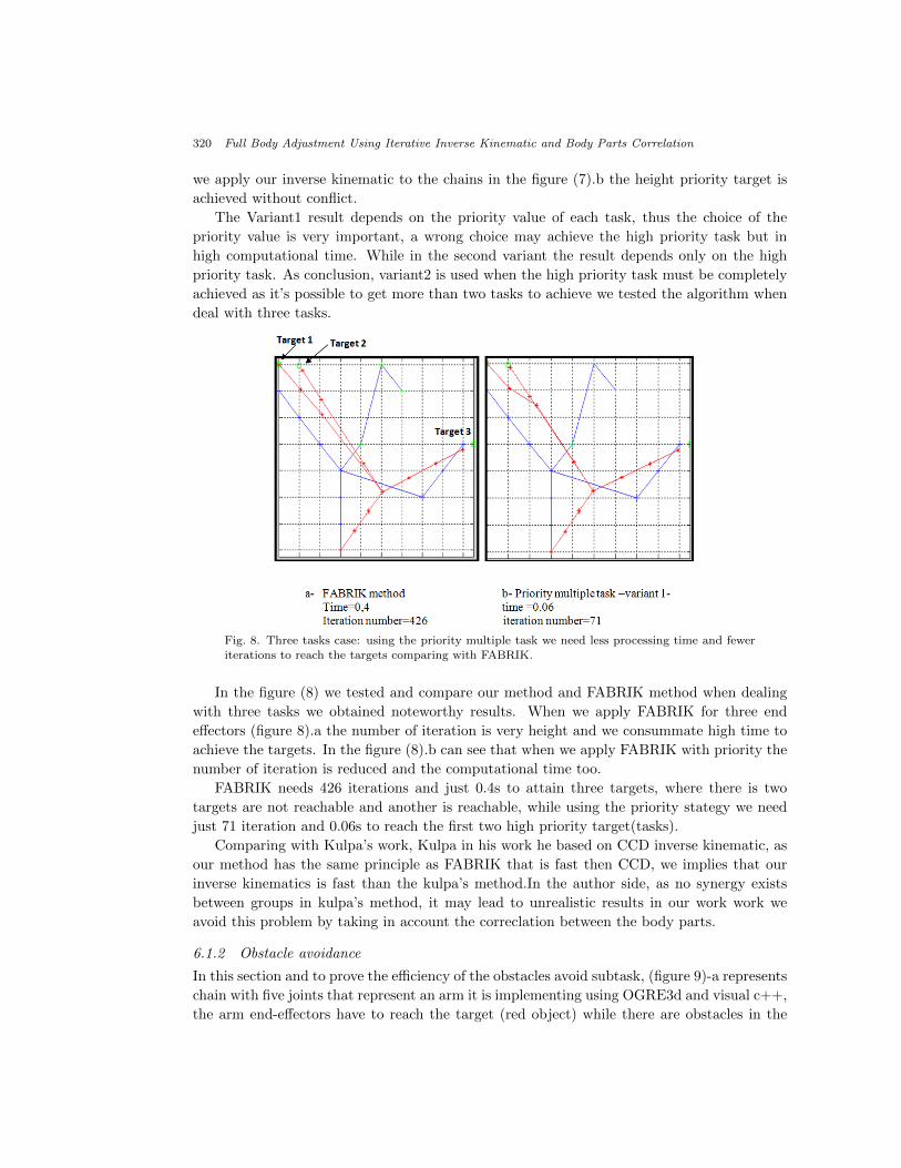
Fig. 8. Three tasks case: using the priority multiple task we need less processing time and fewer
iterations to reach the targets comparing with FABRIK.
In the figure (8) we tested and compare our method and FABRIK method when dealing
with three tasks we obtained noteworthy results. When we apply FABRIK for three end
effectors (figure 8).a the number of iteration is very height and we consummate high time to
achieve the targets. In the figure (8).b can see that when we apply FABRIK with priority the
number of iteration is reduced and the computational time too.
FABRIK needs 426 iterations and just 0.4s to attain three targets, where there is two
targets are not reachable and another is reachable, while using the priority stategy we need
just 71 iteration and 0.06s to reach the first two high priority target(tasks).
Comparing with Kulpa’s work, Kulpa in his work he based on CCD inverse kinematic, as
our method has the same principle as FABRIK that is fast then CCD, we implies that our
inverse kinematics is fast than the kulpa’s method.In the author side, as no synergy exists
between groups in kulpa’s method, it may lead to unrealistic results in our work work we
avoid this problem by taking in account the correclation between the body parts.
6.1.2 Obstacle avoidance
In this section and to prove the efficiency of the obstacles avoid subtask, (figure 9)-a represents
chain with five joints that represent an arm it is implementing using OGRE3d and visual c++,
the arm end-effectors have to reach the target (red object) while there are obstacles in the

A. Bentrah, A. Djeffal, M. Babahenini, C. Gillet, P. Pudlo, and A. Taleb-Ahmed 321
environment (blue and green objects). When we apply FABRIK to reach the target the joints
arm collide with the other objects in the environment (figure 9)-b. But when applying our
inverse kinematic with the obstacle avoidance test, (figure 9)-c represents the result: the end-
effectors reach the target without collision with the obstacles. to improve the realism of the
pose result, we apply the joint limits algorithm respect the biochemical limits of each joint.
Fig. 9. Obstacle avoidance
6.2 Preliminary adjustment method results
6.2.1 Reaching objects
In the first two result subsections, we tested the reliability of our inverse kinematic in in-
dependent chains. Finally, in this section we test the adjustment of the full body method.
Figure 10.a represents the character initial pose, the task is to reach the red object. Applying
the algorithms 1 and 2 we reconstruct the full body pose. In the first case (figure10.b), the
target is close to the character so the trunk keep its initial configuration and just the arm
changes its configuration. This is natural pose because in real life when the target is close we
use just the arm to reach it. We made another test where the target (figure10.c) is far from
the character, in this case the trunk moves to help the arm to reach the task.

322 Full Body Adjustment Using Iterative Inverse Kinematic and Body Parts Correlation
Fig. 10. Reaching objects
6.2.2 Multiple constraints
Fig. 11. Multiple tasks case1
To discuss the performance of our method, in figures 11 and 12, we compare the adjustment
method results to a natural captured pose. In the first case (figure 11) we will use an arm
end effectors of an natural pose as the desired goal position
To test the adjustment we follow two steps:
1. We recover the arm’s end effectors positions from natural pose figure 11(a-b) then we
represent them as spheres,
2. In the other side, we have character in an initial pose, we apply the adjustment method
to it in order that arm’s end-effectors reach the spheres. Figure 11(c-d-e)

A. Bentrah, A. Djeffal, M. Babahenini, C. Gillet, P. Pudlo, and A. Taleb-Ahmed 323
Fig. 12. Multiple tasks case2
In the second case, there are four tasks to reach. We recover the arm’s end-effectors
position and the leg’s end-effector position from natural pose figure 12(a-b) then we represent
them as spheres. We apply the adjustment method to our character that is in it’s initial pose
in order that their four end-effectors -arm’s and legs end effctors- be in their desired positions.
Remarkably, the adjustment result is very close to the natural pose.
Table 1. Comparison between natural and our method’s pose
Angle Natural pose Our method’s poseAng1 Arm1 0.5311 0.5551Ang2 Arm1 0.0003 0Ang3 Arm1 1.4031 0.3182
Table 1 represents comparison between the arm’s joints angle of natural pose and the
adjustment pose where they have the same arm’s end effectors position. We calculate the
angles between the arm’s joint in radian in the both case. As we see the arm’s joint angle of
the natural pose and our pose is almost equal.
6.2.3 Motion retargeting using adjustment method
Due to the good results of the adjustment method, we used it in the motion retargeting
problem to adapt the end-effectors positions to their desired positions in order to respect
environment constraints. One of the main problems in using motion capture data to animate
characters is the problem of retargeting, the motion data is not applicable for other skeleton
and other environment. To facilitate its use, the motion must be edited to meet specific
environmental constraints and/or character proprieties. To solve this problem we apply our
adjustment algorithm to preserve the original motion constraints, as the position of the end
effectors. Figure 13.a represent character pose from motion file, while the character reach an
object. Nevertheless, in the figure 13.b we apply the same data to another character that have
not the same segment length; the character can’t reach the object. Applying our adjustment
method we adapt the motion data to the new character and the character reach the object.

324 Full Body Adjustment Using Iterative Inverse Kinematic and Body Parts Correlation
Fig. 13. Motion retargeting using adjustment method:the adjsutement method is used to adapt
motion data to new morphology
7 Conclusion
In this paper, we propose a new fast method for pose adjustment to new constraints. The
principal idea of the method is to divide the character body into groups and apply an iterative
inverse kinematic to each group in a specific order. The used inverse kinematic method
have the same principle as FABRIK where it uses geometric algebra principle to solve the
problem. Comparing our inverse kinematic with FABRIK, our IK controls multiple end-
effectors without conflict by assigning priority to each task. Beside, the used inverse kinematic
method solves the problem without collision between joints and the environment objects.
Adjust the character body to the new constraints following algorithm 1 has two advantages.
Dividing the character body into groups, that has the advantage to make easy the computation
of a solution. As there is synergy between the groups, where the adjustment of the groups
follows an order and consider the other groups actual and desired configuration, the body
pose is realistic.
In our work, we are taking into account just the kinematic side to adjust the character
pose to new constraint. But, taking just kinematic constraint into consideration may give

A. Bentrah, A. Djeffal, M. Babahenini, C. Gillet, P. Pudlo, and A. Taleb-Ahmed 325
us unrealistic poses. As a future work, we plan to maintain the pose balancing to get more
realistic poses by combining the inverse kinematic and the kinetic in the same algorithm.
Beside, in this paper we presented full adjustement algorithm for one pose. As a future
direction, we would like to sue our method to adjust pose that is part of motion taking into
account the other frames.
8 Acknowledgement
1. This work is under the Hubert Curien Partnership (PHC) of the Tassili scientific coop-
eration and is funded by the French Ministry of Foreign Affairs (MFA) and the Algerian
Ministry of Higher Education and Scientific Research. We thank them all for their help.
2. We thank too Andreas Aristidou to his help.
References
1. Aristidou, Andreas and Lasenby, Joan (2011), FABRIK: a fast, iterative solver for the inversekinematics problem, Graphical Models, Vol 73, n 5, p 243-260, Elsevier
2. Kenwright, Ben (2012), Responsive biped character stepping: When push comes to shove, bookCy-berworlds (CW), International Conference on, p 151-156, IEEE
3. Welman, Chris, (1993),Inverse kinematics and geometric constraints for articulated figure manip-ulation, Simon Fraser University
4. Tolani, Deepak and Goswami (2000), Ambarish and Badler, Norman I, Real-time inverse kine-matics techniques for anthropomorphic limbs, Graphical models,Vol 62, N 5,p 353-388, Elsevier
5. Craig, John J (1989), Introduction to robotics, V 7, Addison-Wesley Reading, MA6. Buss, Samuel R (2004), Introduction to inverse kinematics with jacobian transpose, pseudoinverse
and damped least squares methods, IEEE Journal of Robotics and Automation, Vol 177. Wang, L-CT and Chen, Chih Cheng (1991), A combined optimization method for solving the
inverse kinematics problems of mechanical manipulators, Robotics and Automation, IEEE Trans-actions on, Vol 7, N 4, p 489-499, IEEE
8. Muller-Cajar, R and Mukundan, R (2007), Triangualation-a new algorithm for inverse kinematics,University of Canterbury. Computer Science and Software Engineering.
9. Kulpa, Richard and Multon, Franck and others (2005), Fast inverse kinematics and kinetics solverfor human-like figures., bookHumanoids, p 38-43
10. Badler, Norman I and Manoochehri, Kamran H and Walters, Graham (1987), Articulated figurepositioning by multiple constraints, Computer Graphics and Applications, IEEE, Vol 7, N 6, p28-38
11. Zhao, Jianmin and Badler, Norman I (1994), Inverse kinematics positioning using nonlinear pro-gramming for highly articulated figures, ACM Transactions on Graphics (TOG), Vol 13, N 4, p313-336,
12. Baerlocher, Paolo and Boulic, Ronan (2004), An inverse kinematics architecture enforcing anarbitrary number of strict priority levels, The visual computer, Vol 20, N 6, p 402-417,
13. Siciliano, Bruno and Slotine, J-JE (1991), A general framework for managing multiple tasks inhighly redundant robotic systems, bookAdvanced Robotics, 1991.’Robots in Unstructured Envi-ronments’, 91 ICAR., Fifth International Conference on, p 1211-1216, IEEE
14. Kallman, M and Mataric, Maja (2004), Motion planning using dynamic roadmaps, bookRoboticsand Automation, Proceedings. ICRA’04. 2004 IEEE International Conference on, Vol 5, p 4399-4404
15. Kallmann, Marcelo (2005), Scalable solutions for interactive virtual humans that can manipulateobjects, AIIDE, p 69-75
326 Full Body Adjustment Using Iterative Inverse Kinematic and Body Parts Correlation
16. Shin, Hyun Joon and Lee, Jehee and Shin, Sung Yong and Gleicher, Michael (2001), Computerpuppetry: An importance-based approach, ACM Transactions on Graphics (TOG),
17. Grochow, Keith and Martin, Steven L and Hertzmann, Aaron and Popovic, Zoran (2004), Style-based inverse kinematics, ACM Transactions on Graphics (TOG), Vol 23, N 3, p 522-531
18. Shin, Hyun Joon and Lee, Jehee (2006), Motion synthesis and editing in low-dimensional spaces,Computer Animation and Virtual Worlds, Vol 17, N 3-4, p 219-227, Wiley Online Library
19. Kallmann, Marcelo (2008),Analytical inverse kinematics with body posture control, Computer An-imation and Virtual Worlds,Vol 19, N 79-91,Wiley Online Library
20. Huang, Jing and Pelachaud, Catherine(2012),An efficient energy transfer inverse kinematics so-lution,Motion in Games,N 278-289,Springer