full-azimuth subsurface angle domain wavefield
TRANSCRIPT
Fa
Z
btKfia1SosBta
©
GEOPHYSICS, VOL. 76, NO. 1 �JANUARY-FEBRUARY 2011�; P. S1–S13, 19 FIGS.10.1190/1.3511352 OFFICIAL ONLINE VERSION: http://link.aip.org/link/?GPY/76/S1
ull-azimuth subsurface angle domain wavefield decompositionnd imaging Part I: Directional and reflection image gathers
vi Koren1 and Igor Ravve1
gfestgmbpmtaplloat
ABSTRACT
We present a new subsurface angle-domain seismic imagingsystem for generating and extracting high-resolution informationabout subsurface angle-dependent reflectivity. The system en-ables geophysicists to use all recorded seismic data in a continu-ous fashion directly in the subsurface local angle domain �LAD�,resulting in two complementary, full-azimuth, common-image-angle gather systems: directional and reflection. The completeset of information from both types of angle gathers leads to accu-rate, high-resolution, reliable velocity model determination andreservoir characterization. The directional angle decompositionenables the implementation of specular and diffraction imagingin real 3D isotropic/anisotropic geological models, leading to si-multaneous emphasis on continuous structural surfaces and dis-continuous objects such as faults and small-scale fractures.Structural attributes at each subsurface point, e.g., dip, azimuthand continuity, can be derived directly from the directional angle
ewaac
itiwa2
receivegor.ravv
S1
Downloaded 11 Jan 2011 to 192.117.235.33. Redistribution subject to
athers. The reflection-angle gathers display reflectivity as aunction of the opening angle and opening azimuth. These gath-rs are most meaningful in the vicinity of actual local reflectingurfaces, where the reflection angles are measured with respect tohe derived background specular direction. The reflection-angleathers are used for automatic picking of full-azimuth angle-do-ain residual moveouts �RMO� which, together with the derived
ackground orientations of the subsurface reflection horizons,rovide a complete set of input data to isotropic/anisotropic to-ography. The full-azimuth, angle-dependent amplitude varia-
ions are used for reliable and accurate amplitude versus anglend azimuth �AVAZ� analysis and reservoir characterization. Theroposed system is most effective for imaging and analysis be-ow complex structures, such as subsalt and subbasalt, high-ve-ocity carbonate rocks, shallow low-velocity gas pockets, andthers. In addition, it enables accurate azimuthal anisotropic im-ging and analysis, providing optimal solutions for fracture de-ection and reservoir characterization.
INTRODUCTION
The theory and implementation of so-called true amplitude, ray-ased angle-domain imaging have been intensively studied usinghe Kirchhoff integral and the Born modeling/inversion formula.irchhoff-type migrations invert for the plane-wave reflection coef-cient free of geometrical spreading, assuming the reflection occurslong smooth and continuous interfaces �Bleistein, 1987; Goldin,992; Schleicher et al., 1993; Hubral et al., 1996; Tygel et al., 1996;chleicher et al., 2007�. Born-type migrations/inversions are basedn linearized single scattering of the wavefield within a knownmooth background velocity model. This idea was introduced byeylkin �1985� and Miller et al. �1987� for acoustic migration using
he generalized Radon transform �GRT� and its inverse, and Beylkinnd Burridge �1990� extended the theory for isotropic elastic mod-
Manuscript received by the Editor 28 December 2009; revised manuscript1Paradigm Geophysical, Herzliya, Israel. E-mail: [email protected]; i2011 Society of Exploration Geophysicists.All rights reserved.
ls.Anumerical analysis for the implementation of the inverse GRTith an efficient discretization scheme was proposed by de Hoop
nd Spencer �1996�. De Hoop and Bleistein �1997� and de Hoop etl. �1999� extended the GRT derivation to handle anisotropic modelsontaining either point scatterers or smooth interfaces.
Many papers have been published which study and emphasize themportance of generating common-image-angle gathers directly athe subsurface points rather than the universally used surface-offsetmage gathers, especially in complex geological areas where theavefield includes multipathing �e.g., ten Kroode et al., 1994; Nolan
nd Symes, 1996; Brandsberg-Dahl et al., 1999; Rousseau et al.,000; Xu et al., 2001; Audebert et al., 2002; Koren et al., 2002; Rick-
ett and Sava, 2002; Brandsberg-Dahl et al., 2003; Foss and Ursin,2004; Sollid and Ursin, 2003; Soubaras, 2003; Bleistein et al.,2005a, 2005b; Wu and Chen, 2006; Biondi, 2007a, 2007b�.
d 13 July 2010; published online 4 January [email protected], [email protected].
SEG license or copyright; see Terms of Use at http://segdl.org/

irmatems��ge
dGdThpmlTutmm
“ieotdtpTwt
flntdvm
sffiercsdtismInusTdo
fcacscad
irflwtrf
isWms2dgsmcws
FgLaog
S2 Koren and Ravve
Although the theory of angle-domain imaging is well established,ts implementation, especially for large-scale 3D models or for high-esolution reservoir imaging, remains extremely challenging. A nu-erical implementation of a GRT type of true amplitude ray-based
ngle-domain migration in real 3D complex geological areas, enti-led common reflection-angle migration �CRAM�, has been present-d by Koren et al. �2002�. Unlike conventional ray-based imagingethods, ray tracing is performed from the image points up to the
urface where one-way “diffracted” rays are traced in all directionsincluding turning rays�, forming a system of ray pairs for mappingbinning� the recorded surface seismic data into reflection-angleathers. A similar approach has been proposed in Brandsberg-Dahlt al. �2003� and Sollid and Ursin �2003�.
This paper presents an extension of CRAM, where the imagedata events are decomposed in the local angle domain �LAD� �orRT domain�, into two complementary full-azimuth angle gathers:irectional and reflection �Koren et al., 2007, and Koren et al., 2008�.he combination of the two angle gathers, together with the ability toandle the full-azimuth information in a continuous manner, com-rises a much improved method for subsurface angle-domain seis-ic imaging that enables the generation and extraction of high-reso-
ution information about subsurface angle-dependent reflectivity.he complete set of information from both angle gather types allowss to distinguish between continuous structural surfaces and discon-inuous objects, such as faults and small-scale fractures, leading toore accurate, high-resolution, high-certainty velocity model deter-ination and reservoir characterization.Part I of this paper is organized as follows: The first section,
Method,” provides the main principles and motivations for generat-ng the two complementary angle gathers, emphasizing the new lev-l of information that can be obtained using its applications. The sec-nd section, “Full-azimuth subsurface angle-domain decomposi-ion: directional and reflection gathers,” provides the mathematicaletails used to generate the proposed angle gathers, and describeshe construction of the new 3D cylindrical gathers. Real data exam-les, land and marine, are presented in the “Field examples” section.hese examples demonstrate the strength of the different types ofeighted energy stacks using directional angle gathers, and present
he rich information that can be obtained from the full-azimuth re-
Incident Scattered
Projection of northon reflection plane
Opening angle
Opening azimuth
S R
M^x
^y^z
γ1
γ2
ν1
ν2
igure 1. Example of a selected ray pair �incident and scattered� at aiven subsurface point M and the four angles associated with theAD: dip � 1 and azimuth � 2 of the ray pair normal, opening angle � 1
nd opening azimuth � 2. Four scalar angles describing the directionsf the incident and reflected rays could be related to four LAD an-les, and vice versa.
Downloaded 11 Jan 2011 to 192.117.235.33. Redistribution subject to
ection-angle gathers for kinematic and dynamic analysis. In the fi-al section of the paper, we present our “Conclusions.” In Part II ofhis work we define the local angle domain �LAD� components anderive transformations from the incident and scattered slownessectors to the LAD angles and vice versa, for general anisotropicedia and converted waves.
METHOD
The proposed method follows the concept of imaging and analy-is in the local angle domain �LAD� in isotropy/anisotropy subsur-ace models. Imaging systems involve the interaction of two wave-elds at the image points: incident and scattered �reflected/diffract-d�. Each wavefield can be decomposed into local plane waves �orays�, indicating the direction of propagation.The direction of the in-ident and scattered rays can be described conventionally by their re-pective polar angles. Each polar angle includes two components —ip and azimuth. Note that throughout the paper, the term ray direc-ion refers to the direction of its slowness �or phase velocity�. Themaging stage involves combining a huge number of ray pairs repre-enting the incident and scattered rays. Each ray pair maps the seis-ic data recorded on the acquisition surface into the 4D LAD space.
n our notation, these angles are dip � 1 and azimuth � 2 of the ray pairormal, opening angle � 1 and opening azimuth � 2, as shown in Fig-re 1. Four scalar angles describing the directions of the incident andcattered rays could be related to four LAD angles, and vice versa.hey are mapped as forward and inverse LAD transforms, and theyepend on the medium properties at the scattering point. The detailsf the LAD technique are explained in Part II of this paper.Using an asymptotic ray-based migration/inversion “point dif-
ractor” operator, ray paths, slowness vectors, traveltimes, geometri-al spreading and phase rotation factors are calculated from the im-ge points up to the surface, forming a system for mapping the re-orded surface seismic data into the LAD at the image points. Thetrength of the proposed imaging system is mainly in its ability toonstruct different types of high-quality angle-domain common-im-ge gathers �ADCIG�, representing continuous, full-azimuth, angle-ependent reflectivity in real 3D space.First, we decompose the seismic recorded data into directional
mage gathers. Note that for each direction, seismic data events cor-esponding to ray pairs with the same orientation of the apparent re-ection surface but different opening angles are accounted for in aeighted summation form.The directional gathers contain directivi-
y-dependent information about specular and diffraction energy. Di-ectional data decomposition is associated with what we call “dif-raction imaging,” which is under active research.
True amplitude imaging of point scatterers is extremely challeng-ng. The asymptotic expansions for the amplitude behavior of pointcatterers have been studied by de Vries et al. �1998� and recently byapenaar et al. �2010�. Diffraction imaging in the prestack time do-ain has been intensively studied �e.g., Khaidukov et al., 2004; Ban-
al and Imhof, 2005; Shtivelman and Keydar, 2005; Fomel et al.,006; Taner et al., 2006, and others�. Kozlov et al. �2004� presentediffraction imaging in depth using a “side wave” Kirchhoff-type mi-ration, where the migration aperture was tapered to filter out thepecular energy. Moser and Howard �2008� presented the imple-entation of diffraction imaging in depth for 2D models, providing a
omprehensive review and insight into the potential of diffractionaves to obtain high-resolution images of small-scale discontinuous
ubsurface objects. Recently, Reshef et al. �2009� showed that the
SEG license or copyright; see Terms of Use at http://segdl.org/

seaeeNu
tattzFtIroi
fwsseoogcuf
rtfwjmwaottpwr
aaddtetecmetg
itgtma
msf
baetpic4t2cttfd
Fbcso
Angle domain decomposition and imaging S3
hape of residual moveouts along diffractors within dip-angle gath-rs shows some similarities to specular reflectors along reflection-ngle gathers.Thus, the diffraction energy within the dip-angle gath-rs can be used for high-resolution velocity analysis, especially in ar-as that contain discontinuous objects or along irregular interfaces.ote that in our study, dip-angle gathers are considered to be contin-ous, 3D, full-azimuth directional gathers.The ability to decompose the specular and diffraction energy from
he total scattered field obtained within the full-azimuth directionalngle gathers is the core component of our proposed imaging sys-em. It is based on estimating a directivity-dependent specularity at-ribute which measures the energy within calculated local Fresnelones along the 3D directional gather. The directivity-dependentresnel zones are estimated using precomputed diffraction ray at-
ributes, such as traveltimes, surface locations and slowness vectors.n practice, a specularity directional gather is computed for the cor-esponding seismic directional gather that also allows the extractionf structural subsurface attributes �e.g., dip, azimuth, and specular-ty/continuity� of the local reflecting/diffracting surfaces.
Note that this type of structural information normally is derivedrom postmigration images, created either by ray-based Kirchhoff orave equation migrations, using local coherent event analysis or
tructure-oriented filters. In these migrations, the final image is con-tructed by stacking �averaging� a huge number of seismic events atach image point, accounting for the energy arriving at differentpening angles and for all possible dips. This can result in smearingf the image along key subsurface objects, especially in complexeological areas characterized by faults, pinchouts and material dis-ontinuities. Thus, it is clear that the standard coherence methodssed for extracting the above-mentioned structural information suf-er from inaccuracy, instability, and considerable uncertainty.
The energy �or specularity measurement� computed along the di-ectional angle gather values also is used as a weighted stack opera-or. Two types of images are constructed: specular weighted stacksor emphasizing subsurface structure continuity, and diffractioneighted stacks, which emphasize discontinuities of small-scale ob-
ects such as faults, channels and fracture systems. Note that full-azi-uth directional angle decomposition does not necessarily require aide-azimuth acquisition geometry system; rather, a large migration
perture is needed to allow information from all directions. More-ver, in many cases it is sufficient to use small offsets to create direc-ional angle gathers. For example, it has been shown that nearly ver-ical faults and salt flanks can be detected via simulated corner �du-lex� waves established with directional angle decomposition,here the integration is performed on narrow opening angles �nar-
ow cones� only �Kozlov et al., 2009�.Once background directivity is derived, full-azimuth reflection-
ngle gathers are created by integrating all the dip/azimuth anglesround that direction. Note that if the certainty about the backgroundirectivity is high �measured by the specularity criteria�, only a smallip-angle range around the background direction �estimated fromhe angle-dependent Fresnel zone� is required to capture the specularnergy. The specularity criterion is a measure of the energy concen-ration along the directional angle gathers. The seismic data reflect-d/diffracted from the image points are decomposed/binned intoommon opening �reflection/diffraction� angles and opening azi-uth angles. The full-azimuth reflection-angle gathers are used to
xtract residual moveouts �RMO�, which measure the accuracy ofhe background velocity model used. The full-azimuth RMO, to-ether with the directivity information, comprises the required set of
Downloaded 11 Jan 2011 to 192.117.235.33. Redistribution subject to
nput data for velocity model determination via tomographic solu-ions. In addition, the true amplitude, full-azimuth, reflection-angleathers serve as optimal data for amplitude analysis �AVAZ�, and forhe extraction of high-resolution elastic properties. For these kine-atic and dynamic types of analysis, long offsets and rich azimuths
re particularly effective.
FULL-AZIMUTH SUBSURFACE ANGLE-DOMAINDECOMPOSITION: DIRECTIONAL AND
REFLECTION GATHERS
Our approach consists of three main stages: Ray tracing, full-azi-uth angle-domain decomposition, and final imaging �weighted
tacks�. The ray tracing stage involves shooting a fan of one-way dif-raction rays from image points up to the surface.
The take-off angles are measured around a given local normal to aackground reflection surface �if the background directivity is un-vailable, the vertical axis is assumed�. Ray attributes, such as trav-ltime, ray coordinates, slowness vectors, amplitude and phase fac-ors, are stored for each ray. The full-azimuth angle-domain decom-osition stage involves forming a combination of ray pairs indicat-ng incident and reflected/diffracted rays. Each ray pair maps a spe-ific seismic data event, recorded on the acquisition surface, into aD local angle-domain space in the subsurface — dip and azimuth ofhe ray pair normal, opening angle and opening azimuth �see Figure�. The term “ray pair normal” refers to an apparent normal �alsoalled migration dip vector� computed from Snell’s law for any iso-ropic or anisotropic velocity model, where both incident and scat-ered slowness directions are known.This is a normal to a virtual sur-ace formed by the incident and scattered rays. Note that the specularirection indicates the special case when the ray pair normal coin-
Displacementazimuth
Displacement distance
Offsetazimuth
Offsetdistance
N
R
SCMPN
M´
Reflected ray
Incident ray
Reference azimuth:Projection of northon reflection plane
Opening azimuth
Opening angle
AzimuthDip
M^x
^y ^z
igure 2. Subsurface-to-surface and surface-to-subsurface ray-ased mapping. Each ray pair maps a specific seismic data event re-orded on the acquisition surface, into a 4D local angle-domainpace in the subsurface — dip and azimuth of the ray pair normal,pening angle and opening azimuth.
SEG license or copyright; see Terms of Use at http://segdl.org/

cP
ttmbreamet
m
w�arc
vsectbei
D
am
w
Wb
agiao
w
aptmtfmlt�taw
Tclt
af
cp
t
aTtalao
S4 Koren and Ravve
ides with the normal to a physical reflection surface �see details inart II of this paper�.The four source-receiver surface coordinates �two for the source,
wo for the receiver� are defined according to their displacement vec-or and offset vector. Each vector is defined by its magnitude and azi-uth, where the displacement magnitude is the horizontal distance
etween the source-receiver midpoint and the image location �alsoeferred to as migration aperture distance�. Note that theoreticallyach of the four surface parameters depends on all four LAD angles,nd vice versa. There is, however �especially in moderately complexodels� a stronger dependency between the directional angle gath-
rs and the displacement vector, and between the opening angles andhe offset vector.
The mapping of the surface data U into the subsurface angle do-ain
U�S,R,t�→ I�M,�1,�2,� 1,� 2�, �1�
here M is the subsurface image point, and S� �Sx,Sy�, R�Rx,Ry� are the source and receiver locations, involves generating 7Dngle-domain data �four angles per subsurface point�. This processequires a massive amount of memory throughout the mapping pro-ess and a huge amount of disk space to store the results.
Although this type of mapping �decomposition� can be extremelyaluable for enhancing the imaging and analysis of seismic data, ittill is considered unfeasible even with the largest available comput-rs. We therefore propose splitting the general decomposition pro-ess into two complementary angle-domain image gathers, direc-ional and reflection. At each subsurface point, these image gathersecome functions of only two angles, where integration over the oth-r two angles is performed. We follow the derivation of GRT imag-ng, described in the introduction to this paper.
irectional and reflection seismic gathers
In the directional seismic gathers, the reflectivity/diffractivity I�
t the image point is a function of the ray pair normal dip � 1 and azi-uth � 2,
I��M,�1,�2���K��M,�1,�2,� 1,� 2�H2 sin � 1d� 1d� 2,
�2�
here K� is the kernel of the directional integrand,
K��M,�1,�2,� 1,� 2��W��M,�1,�2,� 1,� 2�
·L�M,�1,�2,� 1,� 2�, �3�
� is the integration weight for directional angle gather, explainedelow, and L is the filtered and amplitude-weighted input data,
L�M,�1,�2,� 1,� 2��D3�S,R,� D�
A�M,S�A�M,R�, �4�
nd H is the obliquity factor, depending primarily on the opening an-le � 1 and explained below. The term “diffractivity” is used here tondicate the reflectivity at nonspecular directions. In the reflection-ngle gathers, the reflectivity I� at the image point is a function of thepening angle � and the opening azimuth � ,
1 2Downloaded 11 Jan 2011 to 192.117.235.33. Redistribution subject to
I� �M,� 1,� 2���K� �M,�1,�2,� 1,� 2�H2 sin �1d�1d�2,
�5�
here K� is the kernel of the reflection integrand,
K� �M,�1,�2,� 1,� 2��W� �M,�1,�2,� 1,� 2�
·L�M,�1,�2,� 1,� 2�, �6�
nd W� is the integration weight for reflection-angle gather, ex-lained below. Thus in both directional and reflection-angle gathers,he integrands include the kernels, the obliquity factor and area ele-ents on the spherical surface. For directional angle gathers, the in-
egration limits are from zero to maximum opening angle � 1max, and
or reflection-angle gathers, the integration limits are from zero toaximum dip angle of the ray pair normal � 1
max, where both upperimits are, of course, less than � . In the azimuthal dimension, the in-egration includes full azimuths, i.e., from zero to 2� for both � 2 and2. The obliquity factor H in equation 2 and equation 5 is the magni-
ude of the slowness sum of the incident and reflected rays, i.e., thebsolute value of the two-way traveltime gradient, which decaysith increasing opening angle � 1,
H��VS
2�M��VR2�M��2VS�M�VR�M�cos � 1
VS�M�VR�M�� ��� D� .
�7�
he expressions VS�M� and VR�M� are the phase velocities of the in-ident and scattered rays, respectively, at the image point. In particu-ar, for an isotropic case, the velocities of the two rays are equal, andhe obliquity factor reduces to
H�2
V�M�cos
� 1
2. �8�
When the opening angle between the two rays approaches straightngle � 1
max→� , the obliquity factor vanishes. Indeed, it followsrom equation 7,
lim H� 1→�
� �VS�1�M��VR
�1�M�� . �9�
Furthermore, straight opening angle means propagation of the in-ident and reflected rays along the same line, and in this case theirhase velocities are equal for a general anisotropy, VS�M��VR�M�.In our notation, both rays are assumed arriving from the surface to
he subsurface image point. Locations
S�S�M,�1,�2,� 1,� 2�, R�R�M,�1,�2,� 1,� 2�
�10�
re the source and receiver coordinates on the acquisition surface�s�.hese coordinates are established by the traced one-way diffrac-
ion rays that connect the given image points with the given sourcend receiver locations. The dependency of the source and receiverocations on the background velocity model and the set of LADngles for each image point makes the implementation of thisutput-driven approach extremely difficult. Parameters
SEG license or copyright; see Terms of Use at http://segdl.org/

aw
u�t
a
w
a
tFrq�mcKepas
icaT�tw
tM
rttfTswaoe
wad
gttflgtdat
FftaScr
s
s
wt
atigera
ttttr
Angle domain decomposition and imaging S5
A�M,S��1
4�·� sin � 1
S�M�VS�M��J�M,S��
,
A�M,R��1
4�·� sin � 1
R�M�VR�M��J�M,R��
�11�
re the amplitudes of Green’s functions �e.g., Bleistein et al., 2001�,here J is the ray Jacobian,
J�dx
d�·
dx
d� 1�
dx
d� 2. �12�
Parameter � is an integration characteristic along the ray, withnits �� �m2·s�1 �m for meter and s for second�, so that �J
m·s, and �A�m–1. Angles � 1 and � 2 are dip and azimuth of theake-off direction at the image point.
The filtered version of the data is �Bleistein et al., 2001; Bleisteinnd Gray, 2002; Koren et al. 2002�,
D3�S,R,� D�S,M,R��1
2�B���
��
iwU�S,R,w�exp�i3�dw,
�13�
here w is the temporal frequency. Parameter 3 is the phase,
3�w� D�S,M,R���
2K�S,M,R�sgn�w�, �14�
nd U�S,R,w� is the input seismic trace in the frequency domain,
U�S,R,w���0
�
U�S,R,t�exp�� iwt�dt . �15�
Assuming arbitrary units �U for the recorded wavefield in theime domain, the wavefield units in the frequency domain are �U · s.actor B in equation 13 is the amplitude of the point-source power,epresenting the constant ratio between the incident field in the fre-uency domain and the corresponding Green’s function; its units areB� �U ·m·s. Thus, the units of the filtered data are �D3�
�1 · s�2. The units of amplitude-weighted data in equation 4 be-ome �L�m·s�2, and the same are the units of the kernels K� and� . Finally the units of the estimated “reflectivity” in equation 2 andquation 5 are �I�m�1. The estimated “reflectivity” can be inter-reted as I�R �s�so�, where R is the actual �unitless� reflectivity,nd �s�so� is 1D Dirac delta-function of normal signed distance�so from the reflector located at so �Bleistein and Gray, 2002�.Parameter K�S,M,R� is the KMAH index, and � D�� D�S,M,R�
s the diffraction stack time. The KMAH index counts the number ofaustics along the traced rays. Recall that caustics refer to pointslong the ray where the determinant of the Jacobian matrix vanishes.wo cases of caustic are distinguished: Jacobian matrix of rank twoinstead of three at regular points�, where the area of the ray tube sec-ion collapses to a line �incrementing KMAH by one�, and rank one,here the area collapses to a point �incrementing KMAH by two�.Equation 15 is the forward real-to-complex Fourier transform of
he input trace U from the time domain to the frequency domain.ultiplying the transformed signal by iw, we get the transformed de-
Downloaded 11 Jan 2011 to 192.117.235.33. Redistribution subject to
ivative. Thus, in the absence of caustics, the inverse transform onhe right side of equation 13 converts the derivative of the input fromhe frequency domain to the time domain. Caustics modify the phaseor the inverse complex-to-real transform according to equation 14.he absolute KMAH index is not essential, but its remainder on divi-ion by four is. Remainders zero and two yield the derivative of data,ith the original and opposite sign, respectively. Remainders one
nd three yield the Hilbert transform of the derivative, also with theriginal and opposite sign, due to the relationship between the Fouri-r transform F and the Hilbert transform HT,
F�HT�P���i sgn�w� ·F�P or
HT�P��F�1�� i sgn�w� ·F�P�, �16�
here P is an arbitrary function; in our case P��U /� t. Recall thatfter the Hilbert transform, the function remains in the same �time�omain.Functions W��M,� 1,� 2,� 1,� 2� and W��M,� 1,� 2,� 1,� 2� are inte-
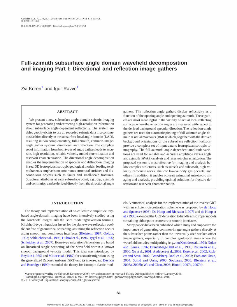
ration weights, inversely proportional to the hit counts �illumina-ion�. Weight W��M,� 1,� 2,� 1,� 2� is estimated for any fixed direc-ional dual angle � 1,� 2 and for a defined proximity of the running re-ection dual angle � 1,� 2 as shown in Figure 3a. Similarly, the inte-ration weight W��M,� 1,� 2,� 1,� 2� is estimated for any fixed reflec-ion dual angle � 1,� 2 and for a defined proximity of the runningirectional dual angle � 1,� 2 as shown in Figure 3b. The proximity iscircle of a preselected radius on the unit sphere �solid angle�, where
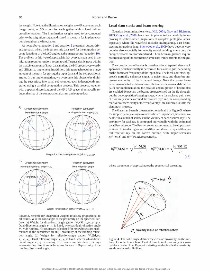
he center of the circle corresponds to the running value.The scheme for computing the integration weights is presented in
igure 4. When the integration through the reflection sphere is per-ormed, the running dual angle � 1,� 2 �black dashed line� is the cen-er of the circular proximity of radius � � , and �̃ 1,�̃ 2 �red solid lines�re the dual reflection angles of multiple ray pairs inside this region.imilarly, on the directional sphere, the running angle � 1,� 2 is theenter of the proximity of radius � �, and �̃ 1,�̃ 2 are multiple dual di-ection angles inside,
in2 �̃ 1�� 1
2�sin �̃ 1 sin� 1 sin2 �̃ 2�� 2
2�sin2� �
2�
A�solid
4�
in2 �̃1��1
2�sin �̃1 sin�1 sin2 �̃2��2
2�sin2� �
2�
A�solid
4�,
�17�
here the right sides are ratios of the proximity areas �solid angles�o the area of the entire sphere 4� .
The rays are shot from the image point and distributed evenly inll directions, so that the given area of the proximity is equivalent tohe fixed number of rays whose starting angles are within the prox-mity radius. Because of the limited migration aperture, acquisitioneometry, and complexity of the background velocity model forach value of a running dual angle, some of the rays in the proximityeach the earth’s surface within the given recording aperture, where-s others do not.
The weight is the ratio of the total number of rays in proximity tohe number of arrivals �assuming there is at least one arrival�. The ra-io of the total number of rays to the number of arrivals is related tohe ratio of the total wavefield amplitude �from the LAD proximity�o the amplitude of the rays �from the same proximity� that reach theecording aperture. The greater the number of arrivals, the smaller
SEG license or copyright; see Terms of Use at http://segdl.org/
ticpt
ecTmtaaaigwd
L
2pespept
aoppetaoors
fdpljtR
w
a
b
FhfD�rt�twr
Ffba
S6 Koren and Ravve
he weight. Note that the illumination weights are 4D arrays per eachmage point, or 5D arrays for each gather with a fixed inline-rossline location. The illumination weights need to be computedrior to the migration stage, and stored in memory for implementa-ion throughout the integration.
As noted above, equation 2 and equation 5 present an output-driv-n approach, where the input seismic data used for the migration be-ome functions of the LAD angles at the image points �equation 10�.he problem in this type of approach is that every ray pair used in theigration requires random access to a different seismic trace within
he massive amount of input data, making the I/O process very costlynd difficult to implement. In addition, this approach requires a hugemount of memory for storing the input data and the computationalrrays. In our implementation, we overcome this obstacle by divid-ng the subsurface into small subvolumes, each independently mi-rated using a parallel computation process. This process, togetherith a special discretization of the 4D LAD space, dramatically re-uces the size of the computational arrays and output data.
Directional subsystem
fixed directional angle ,
Reflection subsystem
running reflection angle γ1 γ2
ν1,ν2proximity β
Weight for directional gather Wν(M,ν1,ν2,γ1,γ2)
)
) Directional subsystem
γ1,γ2proximity β
Weight for reflection gather Wγ(M,ν1,ν2,γ1,γ2)
Reflection subsystem
fixed reflection anglerunning directional angle ν ν1 2,
igure 3. Scheme for integration weights inversely proportional toit counts; � is the cone angle of the proximity on the spherical sur-ace. �a� Weight for directional angle gather, W��M,� 1,� 2,� 1,� 2�.ual directional angle � 1,� 2 is fixed, whereas dual reflection angle1,� 2 is running. Hit counts are calculated for rays whose starting di-
ections in the subsurface are in � -proximity of the running reflec-ion angle. �b� Weight for reflection-angle gather, W��M,� 1,2,� 1,� 2�. Dual reflection angle � 1,� 2 is fixed, whereas dual direc-
ional angle � 1,� 2 is running. Hit counts are calculated for rayshose starting directions in the subsurface are in � -proximity of the
unning directional angle.
Downloaded 11 Jan 2011 to 192.117.235.33. Redistribution subject to
ocal slant stacks and beam steering
Gaussian beam migrations �e.g., Hill, 2001; Gray and Bleistein,009; Gray et al., 2009� have been implemented successfully in im-roving Kirchhoff-based migrations in complex geological areas,specially where the wavefield includes multipathing. Fast beam-teering migrations �e.g., Sherwood et al., 2009� have become veryopular also, especially for velocity model building where only thenergetic beams are stored and used. These beam migrations requirereprocessing of the recorded seismic data traces prior to the migra-ion.
The construction of beams is based on a local tapered slant stackpproach, which normally is performed for a coarse grid, dependingn the dominant frequency of the input data. The local slant stack ap-roach normally enhances signal-to-noise ratio, and therefore im-roves continuity of the structural image. Note that every beamvent is associated with traveltime, shot-receiver areas and directivi-y. In our implementation, the creation and migration of beams alsore enabled. However, the beams are performed on the fly through-ut the decomposition/imaging stage, where for each ray pair, a setf proximity sources around the “source ray” and the correspondingeceivers at the vicinity of the “receiver ray” are collected to form thelant stack process.
The Gaussian beam is presented schematically in Figure 5, whereor simplicity only a single source is shown. In practice, however, weeal with a bunch of sources in the vicinity of each “source ray” Theroximity for each ray is computed individually with the estimatedocal Fresnel zone. The Fresnel zones are assumed to be elliptic pro-ections of circular regions around the central source ray and the cen-ral receiver ray on the earth’s surface, with major semiaxes
Fmaj�M,S� and RF
maj�M,R�, respectively,
RFmaj�M,S���� ��M,S�
fD, RF
maj�M,R���� ��M,R�fD
,
�18�
here parameter � � approximates the geometrical spreading,
igure 4. The solid angle defines the circular proximity on the sur-ace of a reflection sphere. Central direction of proximity is showny black dashed line. Rays with starting angles inside the proximityre shown by red solid lines.
SEG license or copyright; see Terms of Use at http://segdl.org/

wta�Iwpefste
w�obzmrr
Tpdubdo
S
rsdtmmgts
wttapt
shis
F
dscmgdratst
nrtt
Fbbjtrg
Angle domain decomposition and imaging S7
� ��M,S����J�M,S��V3�S�,
� ��M,R����J�M,R��V3�R�, �19�
ith the units �� ��m2 /s. For each ray �“source” and “receiver”�,he ratio between the minor and major semiaxes depends on the dipngle � 1
surf of the phase velocity at the earth surface point, RFmin /RF
maj
cos � 1surf, and the eccentricity of the elliptic zone is � F�sin � 1
surf.n case of a tilted topographic surface, we replace the dip angle � 1
surf
ith the angle between the phase velocity and the normal to the to-ography. Thus the area of the proximity AF��RF
minRFmaj is estimat-
d from the ray Jacobian J of each individual ray and the dominantrequency fD of the recorded data. The slant �slope� used for the localtack is taken from the slowness vectors of the “source ray” pS andhe “receiver ray” pR, respectively. The local tapered slant stackvent can be constructed by
Ubeam�So,Ro,t��1
Nf���S�R
U�So� S,Ro� R,t
� � �f taper� S, R�dSdR, �20�
here Nf is a normalization factor, S� � xS, yS, zS�, R� xR, yR, zR� are the shifts between central and “current” locationsf sources/receivers of the stacked traces within the local areasounded by the Fresnel zones, along the acquisition surface z��x,y�. Function U�So� S,Ro� R,t� � � is the recorded seis-ic data, t� t�M,So,Ro� is the two-way traveltime of the central
ays, f taper� S, R� is a Gaussian taper, and � is the traveltime cor-ection due to the above-mentioned shifts,
� � � S� � R�pxS xS�py
S yS�pzS zS�px
R xR
�pyR yR�pz
R zR. �21�
hus, the construction of the local beams to be migrated for eachoint and each ray pair theoretically is more accurate than the stan-ard beam migrations, where the beam construction is performedniformly prior to the migration.Abeam steering approach can thene applied by measuring the coherency �e.g., semblance� of the can-idate wavelets before the performance of the slant stack, wherenly energetic events are migrated.
pecularity directional gathers
One of the main goals of this work is to provide a method for sepa-ating the specular energy from the total scattered field along theeismic directional gathers. It is assumed that in the actual specularirection, �
1*,�
2*, the coherency measure �semblance� along reflec-
ion events, from all available opening angles � 1 and opening azi-uths � 2, is larger than that along nonspecular directions. To esti-ate the semblance for each direction, two auxiliary directional an-
le gathers are computed: energy and hit count. The energy direc-ional angle gather is computed by integrating the direction kernelquared through all reflection angles,
E��M,�1,�2���K�2�M,�1,�2,� 1,� 2�H4
�sin � 1d� 1d� 2, �22�
Downloaded 11 Jan 2011 to 192.117.235.33. Redistribution subject to
here the kernel K� and the obliquity factor H are defined in equa-ion 3 and equation 7, respectively. Note that all of the three direc-ional angle gathers — seismic I��M,� 1,� 2�, energy E��M,� 1,� 2�,nd hit count N��M,� 1,� 2�, — are computed in the same imagingrocess. The specularity �semblance� gather then is computed fromhese gathers as follows,
fspec�M,�1,�2��1
N�M,�1,�2�·
I�2�M,�1,�2�
E��M,�1,�2�. �23�
In the following section, we show field examples of computedpecularity directional gathers and their application: extractingigh-resolution structural dip and azimuth information, and generat-ng different types of images using specular/diffraction weightedtacks.
ull-azimuth angle-domain common-image gathers
Figure 6 displays a schematic example of the full-azimuth angle-omain common-image gathers. Figure 6a shows a depth migratedection from 3D land data. The vertical line shows a lateral �inline-rossline� location of a specific gather, with an image point in deptharked on this line. A reflection-angle gather at this location, in a
iven azimuth, is shown in Figure 6b. Figure 6c shows two sphericalisplays related to the specific image point. The sphere on the rightepresents the specular and diffused energy as a function of the dip/zimuth direction. The location of the spot on the sphere indicateshat the image point is located in the vicinity of an actual reflectingurface. The orientation of the local reflecting surface is defined byhe dip/azimuth indicated by the maximum energy value.
For a real reflector, the size of the spot on the directional imageormally is a relatively small area in the proximity of the specular di-ection. The specular component is attenuated relative to the scat-ered component. Thus, the size of the spot relates to the measure ofhe energy concentration, where in the vicinity of a real reflector,
Acquisition surface
Fresnel zone
Ray tube
Reflection surface
Input traces
M
SR
surfν1
igure 5. Gaussian beam migration scheme with a single source. Thelue circle �viewed as an ellipse� is the normal cross section of theeam at the arrival point of the central ray. The red ellipse is the pro-ection of the blue circle on the acquisition surface, and it representshe Fresnel zone. The major semiaxis of the red ellipse is equal to theadius of the blue circle. The minor semiaxis depends on the dip an-le of the central ray at the arrival point, � surf.
1SEG license or copyright; see Terms of Use at http://segdl.org/

mir
iapltgr
chppb
R
tt
a
b
Frttttea r.
a
b
F�Ss
S8 Koren and Ravve
ost of the energy will be concentrated in the specular direction, andn the vicinity of diffractors, low energy will be distributed in all di-ections.
The sphere on the left represents the reflectivity versus the open-ng angle and opening azimuth. For a real reflector, high amplitudesre displayed along a relatively large opening angle range that de-ends on the illumination quality caused by the complexity of the ve-ocity model and the data acquisition. The north pole on the direc-ional sphere represents the dip direction coinciding with the back-round reference dip, whereas the north pole on the reflection sphereepresents zero offset or zero opening angle. Figure 6d is a cylindri-
0
1
2
3
4
5
Dep
th(k
m)
0 2.5 5 7.5 10 12.5 15Location (km)
3
60
90
0
30
60
90
120150 180
210
240
270
300
330
Image point
Azimuth (º)Wide-azimuth land data Reflection CIG
Reflection energy
Reflection-angle image gather Cylindrical display: Image
0
1
2
3
4
5
Dep
th(k
m)
0 10 20 30 40 50 60 70 80Opening angle (º)
γ1γ2
z
)
)
c)
d)
Dip (º)
igure 6. Schematic example of full-azimuth angle-domain commoectional and reflection. �a� Depth migrated section from 3D land dataion of a specific gather shown by the vertical line and an image poinhis line. �b� Reflection-angle gather at this lateral location, in a givenion and directional spherical displays related to a specific image poinhe directional sphere represents the dip direction coinciding with thnce dip, and the north pole on the reflection sphere represents zero ongle. �d� Cylindrical display related to all vertical points of the gathe
012345
Dep
th(k
m)
0 1 2 3 4 5 6 7 8 9 10
km10
86
42
0Location (km)
Velocity (km/s)1.5
2.0
2.5
3.0
3.5
4.0
4.5
012345
Dep
th(k
m)
0 1 2 3 4 5 6Location (km
Dip (º)
100%V
6030 0 330
300
Azimuth (º)
Dip (º)
6030 0
Azimuth
)
)
c)
d)
igure 7. Velocity model accuracy. �a� True velocity model of the SEGb� Specularity as a function of dip/azimuth angles at a reflecting suame velocity model with a 10% velocity error applied in region beponding directional specularity.
Downloaded 11 Jan 2011 to 192.117.235.33. Redistribution subject to
al display related to all vertical points of the gather. These pointsave a fixed lateral location and different depths. The cylindrical dis-lay includes a stack of disks, where each disk is related to a specificoint in depth. The disk image is obtained from the spherical imagey projecting or expanding the spherical surface on a plane.
ecommended workflow
Our implementation enables the simultaneous generation of thewo full-azimuth angle gathers: directional and reflection. In prac-ice, however, we recommend a very specific workflow.
First, generate directional angle gathers withrelatively small opening angles �integrating onlydata points with moderate ray pair opening an-gles, for example, below 60°�. The directionalangle gathers require the availability of data fromrich directions �large migration aperture�, but notnecessarily wide-opening angles or wide-open-ing azimuths. Specularity directional angle gath-ers then can be constructed, and specular direc-tions �dip and azimuth� of actual local reflectingsurfaces can be extracted.
Second, generate reflection-angle gathers inthe specular direction, using a small dip range�migration aperture�, with wide opening anglesand all opening azimuths to maximize the avail-able information on the angle-dependent reflec-tivity. Full-azimuth subsurface angle-domain re-sidual moveouts �RMO� then can be automatical-ly picked for high-resolution anisotropic tomog-raphic velocity updating. In addition, amplitudeversus angle and azimuth analysis �AVAZ� can beperformed to enhance reservoir imaging andcharacterization, in particular, fracture detection.
VELOCITY MODEL ACCURACYUSING DIRECTIONAL GATHERS
Figure 7a shows the actual true velocity modelof the SEG/EAGE salt model. Using directionalangle decomposition, the specularity as a func-tion of the dip/azimuth angles at a given reflectingsurface below the salt is shown in Figure 7b. Thespecularity is displayed as a small spot concen-trated in the vicinity of the actual directivity of thegiven reflector.
Figure 7c shows the same velocity model whena 10% velocity error was applied in the region be-low the salt. The corresponding directionalspecularity is shown in Figure 7d. It is clear thatthe energy is smeared �defocused� along the di-rectional unit sphere, indicating the error in thevelocity model and hence the directivity of thegiven reflector.
This example suggests a procedure for quicklyevaluating the integrity of the velocity model.Note that this directivity focusing-analysis ap-proach is considered a complementary approach
180210
240
270
300
330
uth (º)ional CIG
ar energy
r reflectivity
ν2
z
ip (º)
e gathers: di-a lateral loca-th marked onth. �c� Reflec-north pole onground refer-zero opening
1.5
2.0
2.5
3.0
3.5
4.0
Velocity (km/s)
10
km10
86
42
0
300
E salt model.elow salt. �c�lt. �d� Corre-
0
0
120150
AzimDirect
Specul
gathe
ν1
D
n-imag, with
t in depazimut. Thee backffset or
7 8 9)
90%V
330(º)
/EAGrface blow sa
SEG license or copyright; see Terms of Use at http://segdl.org/

ts
rm
E
fnidtc
cmor
whtsedsstt
E
nftsv
F
FKr
F�d
Fe�l
Angle domain decomposition and imaging S9
o the universally used velocity model error analysis, based on mea-uring residual moveouts along reflection-angle gathers.
FIELD EXAMPLES
In this section, we provide field examples of directional-based andeflection-based decomposition for enhancing velocity model deter-ination, and for extracting high-resolution structural attributes.
xample A
Example A shows directional-based imaging using 3D land datarom Egypt, where the subsurface model is characterized by domi-ant overthrust. Figure 8 shows an example of a cylindrical specular-ty directional angle gather, where the specular energy �directivity-ependent Fresnel volume� is emphasized. The high amplitudes ofhe specular energy along the vertical axis indicate the directivityhanges of the subsurface reflectors with depth.
Figures 9a and 10a show the imaging results of the inline androssline sections, respectively, using traditional Kirchhoff-basedigrations. Figures 9b and 10b show the markedly improved resultsbtained when using the specular energy shown in Figure 8 as the di-ectional weighted stack operator,
Ispec�M�� ��1,�2
I��M,�1,�2� · fspecp �M,�1,�2�, �24�
here f spec�M,� 1,� 2� is the specularity gather that measures theigh-energy reflectivity from continuous surfaces, defined by equa-ion 23, and p is an amplifying power index. Each data point in thepecularity gather is a measure of the energy concentration comput-d along the directional angle gather, with a given 3D window —ip, azimuth and depth �Koren et al., 2010�. Figure 11a shows thepecular weighted energy stack at a given line, and views 11b-dhow the same image with an overlay of the extracted structural at-ributes — dip, azimuth and continuity. Figure 12 shows these at-ributes for the entire volume at a given depth.
Azimuth (º)
Azimuth 90º
60
30
0 330 300270
240
Azimuth 270º
Depth (km)
Dip (º)
Specularity0.0
0.1
0.2
0.3
0.4
0.5
0.6
0.7
0.8
0.9
1.0
Dip (º)
igure 8. 3D cylindrical specularity directional angle gather.
Downloaded 11 Jan 2011 to 192.117.235.33. Redistribution subject to
xample B
Figure 13 shows two depth migrated sections from 3D land data inorthwest Germany �owned by RWE-Dea AG and Wintershall AG�ollowing the creation of directional angle gathers. Figure 13a showshe direct stack of the directional angle gathers, and Figure 13b thepecular energy weighted stack of the same gathers. The high energyalues associated with the specular directions sharpen the image of
0
1
2
3
4
Dep
th(k
m)
0 1 2 3 4 5 6 7 8
Location along inline (km)
0 1 2 3 4 5 6 7 8
Location along inline (km)
a) b)
igure 9. Comparison between two images of the same inline. �a�irchhoff migration. �b� Specular weighted energy stack along di-
ectional angle gathers.
0
1
2
3
4
Dep
th(k
m)
0 1 2 3 4 5 6 7 8
Location along crossline (km) Location along crossline (km)
0 1 2 3 4 5 6 7 8
a) b)
igure 10. Comparison between two images of the same crossline.a� Kirchhoff migration. �b� Specular weighted energy stack alongirectional angle gathers.
0.0
0.5
1.0
1.5
2.0
2.5
3.0
3.5
4.0
Dep
th(k
m)
0.00.10.20.30.40.50.60.70.80.91.0
0
10
20
30
40
50
60
70
80
900
45
90
135
180
225
270
315
360
Dip
scal
e(º
)A
zim
uth
scal
e(º
)
Con
tinui
t ysc
ale
Location along inline (km)0 2 4 6 0 2 4 6 0 2 4 6 0 2 4 6 8
Specular stack Dip Azimuth Continuity
a) b) c) d)
igure 11. Depth section along a given line. �a� Specular weightednergy stack. �b� Specular weighted energy stack with dip overlay.c� Specular weighted energy stack with azimuth overlay. �d� Specu-ar weighted energy stack with continuity overlay.
SEG license or copyright; see Terms of Use at http://segdl.org/

ti
gcostc
E
s
eun
E
ecnrwpe
w
i
Fe�l
Falw
Fd
a
Fri
S10 Koren and Ravve
he structure, and the improvement in the continuity of the structuralnformation throughout the volume is seen clearly in Figure 13b.
Figure 14 shows an example of a specularity directional angleather in the vicinity of the salt. Two areas of specular energy arelearly visible, indicating subsurface points which are in the vicinityf conflicting dips, such as unconformities and pinchouts. Thishows that the common assumption that every image point is charac-erized by single directivity is somewhat naïve, and that we also mustonsider all the energetic directions.
xample C
Figure 15 shows an example of imaging in a complex basin in off-horeAustralia. Using directional angle decomposition and specular
8
7
6
5
4
3
2
1
0
7
6
5
4
3
2
1
00 1 2 3 4 5 6 7 0 1 2 3 4 5 6 7 8
Loca
tion
alon
gcr
ossl
ine
(km
)
Location along inline (km)Azimuth Continuity
Specular energy Dip
a) b)
c) d)
igure 12. Depth slice throughout 3D image. �a� Specular weightednergy stack. �b� Specular weighted energy stack with dip overlay.c� Specular weighted energy stack with azimuth overlay. �d� Specu-ar weighted energy stack with continuity overlay.
0
1
2
3
4
5
Dep
th(k
m)
Location along inline (km) Location along inline (km)
a) b)
0 2.5 5 7.5 10 12.5 15 17.5 0 2.5 5 7.5 10 12.5 15 17.5
igure 13. Depth migrated section from a 3D land-marine transitionrea, northwest Germany. �a� Directional angle decomposition fol-owed by normal �no weighting� stack. �b� Image in the same areaith specular energy weighted stack applied.
Downloaded 11 Jan 2011 to 192.117.235.33. Redistribution subject to
nergy weighting, we were able to detect and image a structure �Fig-re 15b� that previously was completely hidden due to noisy data inonspecular directions �Figure 15a�.
xample D
Figure 16 shows two depth slices from a fractured carbonate res-rvoir in the North Sea. Figure 16a demonstrates the resolution thatan be obtained using directional angle decomposition followed byormal stack. Figure 16b shows a high-resolution image of the sameeservoir, emphasizing the fracture system and the channels, thatere obtained by using a diffraction energy weighted stack �as op-osed to the specular energy weighted stack shown in the previousxamples�,
Idiff�M�� ��1,�2
I��M,�1,�2� · fdiffp �M,�1,�2�, �25�
here
fdiff�M,�1,�2��1� fspec�M,�1,�2� �26�
s an operator that decays the specular energy.
Specularity0.0
0.1
0.2
0.3
0.4
0.5
0.6
0.7
0.8
0.9
1.0
0.0
0.2
0.4
0.6
0.8
1.0
1.2
1.4
1.6
Dep
th(k
m)
Azimuth (º)Dip (º)
igure 14. Specularity directional angle gather along pinchout: Twoifferent specular directions at the same depth level.
0.0
0.5
1.0
1.5
2.0
2.5
3.0
3.5
4.0
4.5
5.0
5.5
6.0
Dep
th(k
m)
Location along inline (km)0 5 10 15 20 25 0 5 10 15 20 25
Location along inline (km)
) b)
igure 15. Imaging a “hidden” structure in offshoreAustralia. �a� Di-ectional angle decomposition followed by normal stack. �b� Imagen the same area with specular energy weighted stack applied.
SEG license or copyright; see Terms of Use at http://segdl.org/

5FptTcaad
Ftst
a
Fmsizing the high reflectivity values.
Ffa
a
b
c
Fofbflp
Angle domain decomposition and imaging S11
Downloaded 11 Jan 2011 to 192.117.235.33. Redistribution subject to
Full-azimuth reflection-angle gathers were created using equation.An example of a 3D reflection-angle gather in this area is shown inigure 17. It is displayed as a cylinder �Figure 17a� and with trans-arency �Figure 17b�, so that the full dimensionality of the ampli-ude versus opening angle and opening azimuth can be studied.hese full-azimuth image gathers can provide diagnostic qualityontrol regarding the accuracy of the velocity models, and enable theutomatic detection of residual moveout �RMO� errors. The gatherslso can be sampled in full-angle or full-azimuth sectors to better un-erstand the influence of azimuth on the velocity model, and to better
understand the behavior of seismic amplitude as afunction of opening angle and azimuth. Figure 18shows 20 azimuthal sectors of reflection-anglegathers that were extracted on the fly from the cy-lindrical gather shown in Figure 17. Figure 19ashows five extracted opening angle sectors �20°,30°, 40°, 50°, and 60°�, each of which displaysfull-azimuth reflections.
The azimuthally varying reflector indicates anazimuthal anisotropic effect, and is marked by arectangle. In Figure 19b, the reflector is magni-fied and overlain by automatic RMO picks, whichare used to flatten the event �Figure 19c�. Al-though azimuthally varying reflectors can resultfrom lateral heterogeneity, in this example the tar-get area is known to be a fractured carbonate res-
0
30
60
90
120
150
180
210
240
270
300
330
360
Azi
mut
h(º
)
ely extracteds, indicating
0.0
0.5
1.0
1.5
2.0
2.5
3.0
3.5
4.0
4.5
5.0
Dep
th(k
m)
20 30 40 50 60Opening angle sectors (º)
0
10
20
30
40
50
60
70
80
Ope
ning
angl
e(º
)
Dep
th(k
m)
Dep
th(k
m)
3.4
3.5
3.6
3.4
3.5
3.6
Azimuth (º)0 30 60 90 120 150 180 210 240 270 300 330 360
)
)
)
igure 19. Full-azimuth reflection-angle event. �a� Five extractedpening angle sectors �20°, 30°, 40°, 50°, and 60°�, each displayingull-azimuth reflections. The azimuthally varying reflector, markedy a rectangle, indicates an azimuthal anisotropy effect. �b� The re-ector is magnified and overlain by automatic RMO picks. �c� RMOicks are used to flatten the event.
4
3
2
1
00 1 2 3 4 5 6 7 8
Loca
tion
alon
gcr
ossl
ine
(km
)
Location along inline (km)
a)
4
3
2
1
00 1 2 3 4 5 6 7 8
Loca
tion
alon
gcr
ossl
ine
(km
)
Location along inline (km)
b)
igure 16. Two depth slices from a fractured carbonate reservoir inhe North Sea. �a� Image obtained using directional angle decompo-ition followed by normal stack. �b� Image with high-resolution fea-ures obtained using diffraction energy weighted stack.
2.02.22.42.62.83.03.23.43.63.84.0
Opening azimuth
Opening angle (º)
–1.0–0.8–0.6–0.4–0.20.00.20.40.60.81.0
Dep
th(k
m)
Nor
mal
ized
seis
mic
ampl
itude
040
80
180º270º
0º
90º
)
0.00.10.20.30.40.50.60.70.80.91.0
2.02.22.42.62.83.03.23.43.63.84.0
Opening azimuth
Opening angle (º)
Dep
th(k
m)
Nor
mal
ized
refle
ctiv
ity
040
80
180º270º
0º
90º
b)
igure 17. 3D cylindrical reflection-angle gather. �a� Selected azi-uthal sector. �b� Full 3D volume with transparency mode, empha-
0.0
0.5
1.0
1.5
2.0
2.5
3.0
3.5
4.0
4.5
5.0
Dep
th(k
m)
0 18 36 54 72 90 108 126 144 162 180 198 216 234 252 270 288 306 324 342Azimuthal sectors (º)
igure 18. Twenty azimuthal sectors of reflection-angle gathers interactivrom the 3D cylindrical gather. Residual moveout curves vary with azimuthzimuthal anisotropy effect.
SEG license or copyright; see Terms of Use at http://segdl.org/

em
ugvrrirmtat
ttotfluvaafpe
poccia
CsSbtpSatts
A
B
B
B
B
B
B
B
B
B
B
B
B
d
d
d
d
F
F
G
G
G
H
H
K
K
K
K
K
K
K
M
S12 Koren and Ravve
rvoir with many external supported indications, e.g., vertical seis-ic profiling �VSP� information and S-waves.
CONCLUSIONS
This paper presents a novel imaging system for generating contin-ous, full-azimuth, angle-domain image gathers. The set of four an-les within the local angle domain is introduced. Forward and in-erse transforms between the LAD and the directions of incident andeflected rays are described. Although the method is presented as aay-based imaging approach, the theory is valid for wave equationmaging as well. Two complementary angle gathers, directional andeflection, deliver high-resolution information about the subsurfaceodel. In particular, the new directional image gathers allow the au-
omatic extraction of geometrical attributes, such as dip, azimuthnd specularity/continuity, and enable the generation of differentypes of images by weighting either specular or diffraction energy.
It has been shown that several specular directions might coexist athe same image point, associated with conflicting dips �unconformi-ies and pinchouts�. Continuous structure surfaces and discontinu-us subscale small objects, such as channels and fractures, can be de-ected, even below complex geological structures. Full-azimuth re-ection-angle gathers provide information about full-azimuth resid-al moveouts, and therefore measure the accuracy of the backgroundelocity model from all angles and azimuths. In particular, the full-zimuth RMO can be used as indicators of the existence of azimuthalnisotropy effects due to fractures. In addition, the true amplitude,ull-azimuth reflection-angle gathers serve as optimal data for am-litude analysis �AVAZ�, and for the extraction of high-resolutionlastic properties.
The full-azimuth angle-domain decomposition performed inde-endently for every image point enables control and customizationf the locality, direction, and scope of the area being studied, and theorresponding seismic data.The system, therefore, might be used lo-ally as a target-oriented system for direct, high-resolution reservoirmaging, as well as globally for full-volume imaging of massivemounts of data.
ACKNOWLEDGMENTS
We thank Allon Bartana, Edip Baysal, Anat Canning, Davidhase, Duane Dopkin, Adam Farris, Ofra Kalechshtain, Dan Ko-
loff, Evgeny Kozlov, Ronit Levy, Beth Orshalimy, Evgeny Ragoza,.P. Singh, and many other colleagues at Paradigm for their contri-ution to the development work leading to this paper.We are gratefulo Norman Bleistein for the valuable discussions, and to the Geo-hysics editors and reviewers Jose Carcione, Ivan Vasconcelos,tig-Kyrre Foss and Samuel Gray for their many valuable commentsnd suggestions, which helped to improve the content and style ofhis paper. We would also like to thank RWE-Dea and our other cus-omers for their collaboration and permission to use their data in thistudy.
REFERENCES
udebert, F., P. Froidevaux, H. Rakotoarisoa, and J. Svay-Lucas, 2002, In-sights into migration in the angle domain: 72nd Annual InternationalMeeting, SEG, ExpandedAbstracts, 1188–1191.
ansal, R., and M. G. Imhof, 2005, Diffraction enhancement in prestack seis-mic data: Geophysics, 70, no. 3, V73–V79, doi: 10.1190/1.1926577.
eylkin, G., 1985, Imaging of discontinuities in the inverse scattering prob-
Downloaded 11 Jan 2011 to 192.117.235.33. Redistribution subject to
lem by inversion of a casual generalized Radon transform: Journal ofMathematical Physics, 26, 99–108, doi: 10.1063/1.526755.
eylkin, G., and R. Burridge, 1990, Linearized inverse scattering problemsin acoustics and elasticity: Wave Motion, 12, 15–52, doi: 10.1016/0165-2125�90�90017-X.
iondi B., 2007a, Angle-domain common-image gathers from anisotropicmigration: Geophysics, 72, no. 2, S81–S91, doi: 10.1190/1.2430561.
iondi, B., 2007b, Residual moveout in anisotropic angle-domain common-image gathers: Geophysics, 72, no. 2, S93–S103, doi: 10.1190/1.2430562.
leistein, N., 1987, On the imaging of reflectors in the earth: Geophysics, 52,931–942, doi: 10.1190/1.1442363.
leistein, N., J. K. Cohen, and J. W. Stockwell Jr., 2001, Mathematics of mul-tidimensional seismic imaging, migration, and inversion: Springer.
leistein, N., and S. H. Gray, 2002, A proposal for common-opening-anglemigration/inversion: Center for Wave Phenomena, Colorado School ofMines, Research Report CWP-420.
leistein, N., Y. Zhang, S. Xu, G. Zhang, and S. H. Gray, 2005a, Kirchhoffinversion in image point coordinates recast as source/receiver point pro-cessing: 75th Annual International Meeting, SEG, Expanded Abstracts,1697–1700.
leistein, N., Y. Zhang, S. Xu, G. Zhang, and S. H. Gray, 2005b, Migration/inversion: think image point coordinates, process in acquisition surfacecoordinates: Inverse Problems, 21, 1715–1744, doi: 10.1088/0266-5611/21/5/013.
randsberg-Dahl, S., M. V. de Hoop, and B. Ursin, 2003, Focusing in dip andAVA compensation on scattering-angle/azimuth common image gathers:Geophysics, 68, 232–254, doi: 10.1190/1.1543210.
randsberg-Dahl, S., M. V. de Hoop, and B. Ursin, 1999, Velocity analysis inthe common scattering-angle/azimuth domain: 69th Annual InternationalMeeting, SEG, ExpandedAbstracts, 1715–1718.
e Hoop, M. V., and N. Bleistein, 1997, Generalized Radon transform inver-sions for reflectivity in anisotropic elastic media: Inverse Problems, 13,669–690, doi: 10.1088/0266-5611/13/3/009.
e Hoop, M. V., and C. Spencer, 1996, Quasi-Monte Carlo integration overS2�S2 for migration� inversion: Inverse Problems, 12, 219–239.
e Hoop, M. V., C. Spencer, and R. Burridge, 1999, The resolving power ofseismic amplitude data: An anisotropic inversion/migration approach:Geophysics, 64, 852–873, doi: 10.1190/1.1444595.
e Vries, P., D. V. van Coevorden, and A. Lagendijk, 1998, Point scatterersfor classical waves: Reviews of Modern Physics, 70, 447–466, doi:10.1103/RevModPhys.70.447.
omel, S., E. Landa, and M. T. Taner, 2006, Post-stack velocity analysis byseparation and imaging of seismic diffractions: 76th Annual InternationalMeeting, SEG, ExpandedAbstracts, 2559–2563a.
oss, S.-K., and B. Ursin, 2004, 2.5-D modeling, inversion and angle-migra-tion in anisotropic elastic media: Geophysical Prospecting, 52, 65–84, doi:10.1046/j.1365-2478.2004.00400.x.
oldin, S., 1992, Estimation of reflection coefficient under migration of con-verted and monotype waves: Soviet Geology and Geophysics, 33, 76–90.
ray, S. H., and N. Bleistein, 2009, True-amplitude Gaussian-beam migra-tion: Geophysics, 74, no. 2, S11–S23, doi: 10.1190/1.3052116.
ray, S. H., Y. Xie, C. Notfors, T. Zhu, D. Wang, and C.-O. Ting, 2009, Tak-ing apart beam migration: The Leading Edge, 28, 1098–1108, doi:10.1190/1.3236380.
ill, N. R., 2001, Prestack Gaussian-beam depth migration: Geophysics, 66,1240–1250, doi: 10.1190/1.1487071.
ubral, P., J. Schleicher, and M. Tygel, 1996, Aunified approach to 3-D seis-mic reflection imaging, Part I: Basic concepts: Geophysics, 61, 742–758,doi: 10.1190/1.1444001.
haidukov, V., E. Landa, and T. J. Moser, 2004, Diffraction imaging by fo-cusing-defocusing: An outlook on seismic superresolution: Geophysics,69, 1478–1490, , doi: 10.1190/1.1836821.
oren, Z., I. Ravve, A. Bartana, and D. Kosloff, 2007, Local angle domain inseismic imaging: 69th Conference and Exhibition, EAGE, Extended Ab-stracts, P287.
oren, Z., I. Ravve, and R. Levy, 2010, Specular-diffraction imaging fromdirectional angle decomposition: 72nd Conference and Exhibition,EAGE, ExtendedAbstracts, G045.
oren, Z., I. Ravve, E. Ragoza, A. Bartana, and D. Kosloff, 2008, Full-azi-muth angle domain imaging: 78th Annual International Meeting, SEG,ExpandedAbstracts, 2221–2225.
oren, Z., X. Sheng, and D. Kosloff, 2002, Target-oriented common reflec-tion angle migration: 72ndAnnual International Meeting, SEG, ExpandedAbstracts, 1196–1199.
ozlov, E., N. Barasky, E. Korolev, A. Antonenko, and E. Koshchuk, 2004,Imaging scattering objects masked by specular reflections: 74th AnnualInternational Meeting, SEG, ExpandedAbstracts, 1131–1134.
ozlov, E. A., Z. Koren, D. N. Tverdohlebov, and A. N. Badeikin, 2009, Cor-ner reflectors — a new concept of imaging vertical boundaries: 71st Con-ference and Exhibition, EAGE, ExtendedAbstracts, Z039.iller, D., M. Oristaglio, and G. Beylkin, 1987, Anew slant on seismic imag-
SEG license or copyright; see Terms of Use at http://segdl.org/

M
N
R
R
R
S
S
S
S
S
S
T
t
T
W
W
X
Angle domain decomposition and imaging S13
ing: Migration and integral geometry: Geophysics, 52, 943–964, doi:10.1190/1.1442364.ozer, T. J., and C. B. Howard, 2008, Diffraction imaging in depth: Geo-physical Prospecting, 56, 627–641, doi: 10.1111/j.1365-2478.2007.00718.x.
olan, C., and W. Symes, 1996, Imaging in complex velocities with generalacquisition geometry: TRIP, the Rice Inversion Project, Rice University,technical report.
eshef, M., N. Lipzer, and E. Landa, 2009, Interval velocity analysis in com-plex areas — azimuth considerations: 71st Conference and Exhibition,EAGE, ExtendedAbstracts, U010.
ickett, J. E., and P. C. Sava, 2002, Offset and angle-domain common image-point gathers for shot-profile migration: Geophysics, 67, 883–889, doi:10.1190/1.1484531.
ousseau, V., L. Nicoletis, J. Svay-Lucas, and H. Rakotoarisoa, 2000, 3Dtrue amplitude migration by regularisation in angle domain: 62nd Confer-ence and Exhibition, EAGE, ExtendedAbstracts, B-13.
chleicher, J., M. Tygel, and P. Hubral, 2007, Seismic true-amplitude imag-ing: SEG Geophysical Developments Series No. 12.
chleicher, J., M. Tygel, and P. Hubral, 1993, 3-D true-amplitude finite-off-set migration: Geophysics, 58, 1112–1126, doi: 10.1190/1.1443495.
herwood, J. W. C., K. Sherwood, H. Tieman, and K. Schleicher, 2009, 3Dbeam prestack depth migration with examples from around the world: TheLeading Edge, 28, 1120–1127, doi: 10.1190/1.3236382.
htivelman, V., and S. Keydar, 2005, Imaging shallow subsurface inhomoge-
Downloaded 11 Jan 2011 to 192.117.235.33. Redistribution subject to
neities by 3D multipath diffraction summation: First Break, 23, 39–42.ollid, A., and B. Ursin, 2003, Scattering-angle migration of ocean-bottomseismic data in weakly anisotropic media: Geophysics, 68, 641–655, doi:10.1190/1.1567234.
oubaras, R., 2003, Angle gathers for shot-record migration by local har-monic decomposition: 73rd Annual International Meeting, SEG, Expand-edAbstracts, 889–892.
aner, M. T., S. Fomel, and E. Landa, 2006, Separation and imaging of seis-mic diffractions using plane-wave decomposition: 76th Annual Interna-tional Meeting, SEG, ExpandedAbstracts, 2401–2405.
en Kroode, A. P. E., D. J. Smit, and A. R. Verdel, 1994, Linearized inversescattering in the presence of caustic: SPIE — The International Society forOptical Engineering, ExpandedAbstracts, 28–42.
ygel, M., J. Schleicher, and P. Hubral, 1996, Aunified approach to 3-D seis-mic reflection imaging, part II: Theory: Geophysics, 61, 759–775, doi:10.1190/1.1444002.apenaar, K., E. Slob, and R. Snieder, 2010, On seismic interferometry, thegeneralized optical theorem, and the scattering matrix of a point scatterer:Geophysics, 75, no. 3, SA27–SA35, doi: 10.1190/1.3374359.u, R.-S., and L. Chen, 2006, Directional illumination analysis using beam-let decomposition and propagation: Geophysics, 71, no. 4, S147–S159,doi: 10.1190/1.2204963.
u, S., H. Chauris, G. Lambaré, and M. Noble, 2001, Common-angle migra-tion: A strategy for imaging complex media: Geophysics, 66, 1877–1894,doi: 10.1190/1.1487131.
SEG license or copyright; see Terms of Use at http://segdl.org/