fuel cell technology
TRANSCRIPT
A
SEMINAR
ON
“FUEL CELL”
SUBMITTED IN PARTIAL FULFILLMENT OF
REQUIREMENT OF THE DEGEE OF
BACHELOR OF TECHNOLOGY
IN
ELECTRICAL ENGINEERING
SUPERVISED BY: SUBMITTED BY:
Prof. ASAD ZAI Jasraj
Roll No. – 13EVEEE014
DEPARTMENT OF ELECTRICAL ENGINEERING
VYAS COLLEGE OF ENGINEERING AND TECHNOLOGY, JODHPUR
RAJASTHAN TECHNICAL UNIVERSITY, KOTA
2017
~ i ~
CERTIFICATE
This is to certify that the student Mr. Jasraj of final year, have successfully
completed the seminar presentation on “Fuel Cell” towards the partial
fulfilment of the degree of Bachelors of Technology (B. TECH) in the Electrical
Engineering of the Rajasthan Technical University during academic year
2017 under my supervision.
The work presented in this seminar has not been submitted elsewhere for award
of any other diploma or degree.
Prof. Asad Zai
Supervisor
Professor
Deptt. of Electrical Engineering
VIET, Jodhpur.
Counter Signed by:
Prof. Manish Bhati
Head Deptt. of Electrical Engg.
VIET, Jodhpur.

~ ii ~
ACKNOWLEDGEMENT
First of all, I thank the God Almighty for His grace and mercy that enabled me in the
finalization of this seminar. Secondly I would also like to thank my Parents and Sister
who helped me a lot in finalizing this project within the limited time frame.
Every seminar big or small is successfully largely due to effort of a number of
wonderful people who have always given their valuable advice or lent a helping hand.
I sincerely appreciate the inspiration, support and guidance of all those people who
have been instrumental in making this seminar a successful.
I wish to express of gratitude to my guile to Prof. Asad Zai, Electrical Engineering
Department to give me guidance at every moment during my entire thesis and giving
valuable suggestion. He gives me unfailing inspiration and whole hearted co-operation
in caring out my seminar work. His continuous encouragement at each work and effort
to the push work are grateful acknowledged.
I am also grateful to Prof. Manish Bhati, Head of the Department, Electrical
Engineering for giving me the support and encouragement that was necessary for the
completion of this seminar.
JasRaj
~ iii ~
ABSTRACT
Technology is increasing our energy needs, but it is also show in new ways to
generate power more effetely with less impact on the environment. One of the most
promising options for supplementing future power supplies is the fuel cells.
A fuel cell is a device that electrochemically converts the chemical energy of a fuel
and an oxidant to electrical energy. The fuel and oxidant are typically stored outside
of the fuel cell and transferred into the fuel cell as the reactants are consumed. The
most common type of fuel cell uses the chemical energy of hydrogen to produce
electricity, with water and heat as by-products. Fuel cells are unique in terms of the
variety of their potential applications; they potentially can provide energy for systems
as large as a utility power station and as small as a laptop computer. Fuel cells have
several potential benefits over conventional combustion- based technologies currently
used in many power plants and passenger vehicles. They produce much smaller
quantities of greenhouse gases and none of the air pollutants that create smog and
cause health problems. If pure hydrogen is used as a fuel, fuel cells emit only heat and
water as a byproduct.
~ iv ~
TABLE OF CONTANTS
CERTIFICATE ........................................................................... i
ACKNOWLEDGEMENT........................................................... ii
ABSTRACT ................................................................................. iii
TABLE OF CONTANTS ........................................................... iv
LIST OF FIGURES .................................................................... vi
1 Introduction ....................................................................... 1
1.1 What is fuel Cell ................................................................. 2
2 Hydrogen Fuel Cell ........................................................... 3
2.1 Polymer Electrolyte Membrane Fuel cell ........................... 3
2.2 Molten Carbonate Fuel Cell ................................................ 3
2.3 Solid Oxide Fuel Cell ......................................................... 3
2.4 Phosphoric Acid Fuel Cell .................................................. 3
3 MAJOR COMPONETS .................................................... 6
4 DESIGNING of Fuel Cell ................................................... 8
4.1 PROTON EXCHANGE MEMBRANE FUEL CELLS ...... 8
5 FUEL CELL EFFICIENCY ............................................ 13
APPLICATIONS ............................................................... 15
ADVANTAGES ................................................................ 16
CONCLUSION .................................................................. 18

~ v ~
LIST OF FIGURES
1 Fuel Cell Car Model ................................................................. 3
2 Fuel Cell Working .................................................................... 6
3 Phosphoric acid fuel cell ........................................................... 9
4 A block diagram of a fuel cell .................................................. 9
5 Proton exchange membrane fuel cell ........................................ 10
6 Reaction diagram of Hydrogen-oxygen fuel cell ..................... 11

[1]
Chapter-1
INTRODUCTION
Technology is increasing our energy needs, but it is also showing in new ways to generate
power more effetely with less impact on the environment. One of the most promising
options for supplementing future power supplies is the fuel cells. they have the potential to
create much more reliable power, with lower levels of undesirable emissions and noise and
higher overall efficiency than more traditional power generation systems with existing and
projected applications ranging from space craft to private automobiles, large stationary
power generator systems to small electronic devices, fuel cells are poised to play an
increasingly critical role in meeting the world’s plowing demand for clean, reliable power.
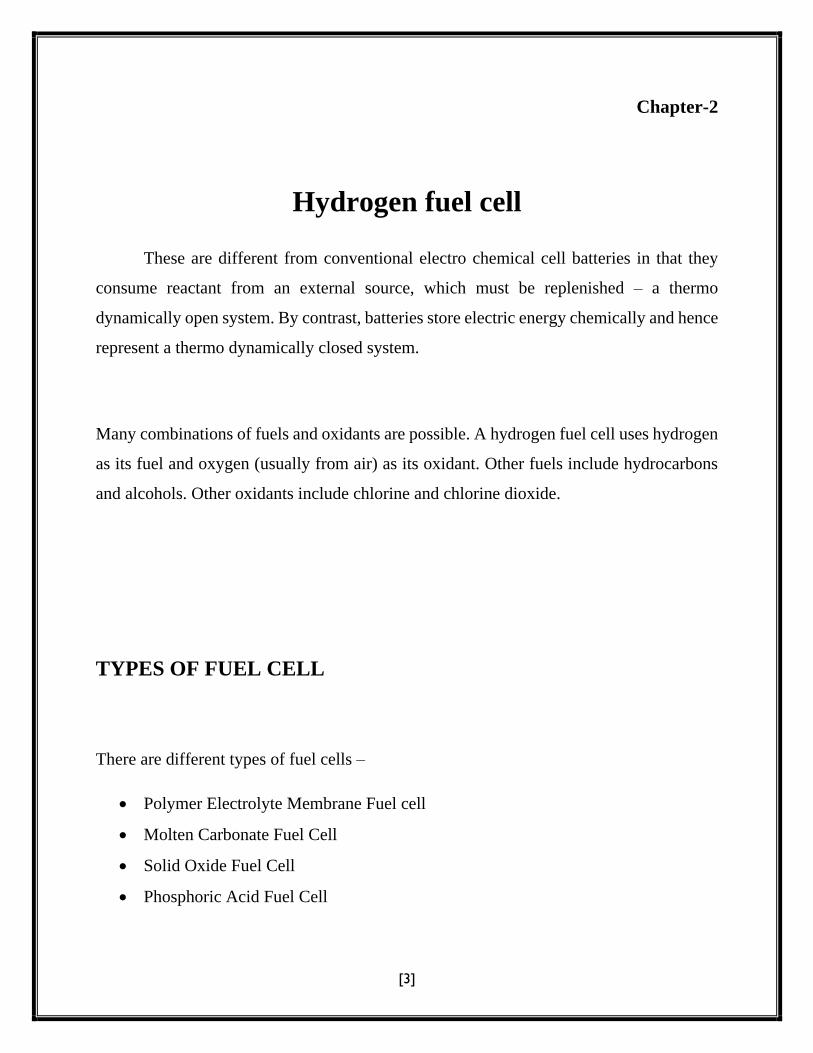
Fig 1: Fuel Cell Car Model

[2]
WHAT IS FUEL CELL?
Fuel cell is an electro chemical energy device which converts chemical hydrogen
and oxygen to produce electricity by slipping electrons from hydrogen. Hydrogen is
exceeded from natural gun, propane and other common fuel cell and oxygen is from air.
Electricity is generated from the reaction between a fuel supply and an oxidizing
agent. The reactance flow into the cell and the reaction products flow out of it, while the
electrolyte remains within it. Fuel cells can operate continuously as long as the necessary
reactant and oxidant flow are maintained.
Fig 2: Fuel Cell Working
[3]
Chapter-2
Hydrogen fuel cell
These are different from conventional electro chemical cell batteries in that they
consume reactant from an external source, which must be replenished – a thermo
dynamically open system. By contrast, batteries store electric energy chemically and hence
represent a thermo dynamically closed system.
Many combinations of fuels and oxidants are possible. A hydrogen fuel cell uses hydrogen
as its fuel and oxygen (usually from air) as its oxidant. Other fuels include hydrocarbons
and alcohols. Other oxidants include chlorine and chlorine dioxide.
TYPES OF FUEL CELL
There are different types of fuel cells –
Polymer Electrolyte Membrane Fuel cell
Molten Carbonate Fuel Cell
Solid Oxide Fuel Cell
Phosphoric Acid Fuel Cell
[4]
1. Polymer Electrolyte Membrane Fuel cell:
PEMFC consists of a proton conducting membrane. This polymer membrane is very
thin, 20-200 micrometers, flexible and transparent. The membrane is coated on both sides
with platinum (Pt) impregnated porous carbon electrode. The membrane electrode
assembly (MEA) is approximately 1mm thick. The operating temperature of the PEMFC
is to 90 deg C or lower because the polymer membrane must be hydrated with liquid water
to maintain adequate conductivity. Because of this low operating temperature, the Platinum
based catalyst is the only viable option.
The PEMFC has the highest power density with a range of 300-1000mW/cm2 and
offers the most reliable fast start and on-off cycling. These characteristics make this fuel
cell type highly suitable for transport applications and portable power although there are
power generation applications currently available on the market.
2. Molten Carbonate Fuel Cell:
The MCFC is a mixture of alkali (Na and K) carbonates Li2CO3 And K2CO3
retained in a ceramic matrix of LiOAlO2. The cell operates at temperature of 1100 to 1300
deg F or 600to 700 deg C in order to keep the alkali carbonates in a highly conductive
molten salt form, the carbonate ions providing ionic conduction. The electrodes are
typically nickel based. Where the anode is a nickel/chromium alloy and the cathode is a
lithiated nickel oxide. As CO2 is generated at the anode it is typically recycled to the
cathode where it is consumed and since it is preheated by combustion this improves the
overall efficiency of the cell.

[5]
Because of the high temperature the MCFC can take a variety of fuel types such as
methane, hydrogen, alcohols, and CO poisoning is nonexistent in fact the carbon monoxide
acts as a fuel. The MCFC is the best used in stationary applications like power generation
and can achieve electrical efficiencies of goes up to 50%. In combined heat and power
applications the efficiencies go up to 90%.
3. Solid Oxide Fuel Cell:
Solid oxide fuel cells (SOFCs) offer substantial potential for heat and power
generation. They promise to be useful in large, high-power applications such as full-scale
industrial and large scale electricity generating stations. Some fuel cell developers see
SOFCs being used in motor vehicles. A SOFC system usually utilizes a solid ceramic as
the electrolyte and operates at high temperatures (973–1,273 K) and this high temperature
is beneficial for co-generation of both electricity and high-grade heat at user sites, thus,
increasing total system efficiency to about 85%.
Further, this high operating temperature allows internal reforming, promotes rapid electro
catalysis with non-precious metals, and produces high quality byproduct heat for co-
generation.
4. Phosphoric Acid Fuel Cell:
The electrolyte consists of highly concentrated or pure, liquids phosphoric acid
(H3PO4) saturated in a silicon carbide matrix (SiC); on either side of the electrolyte
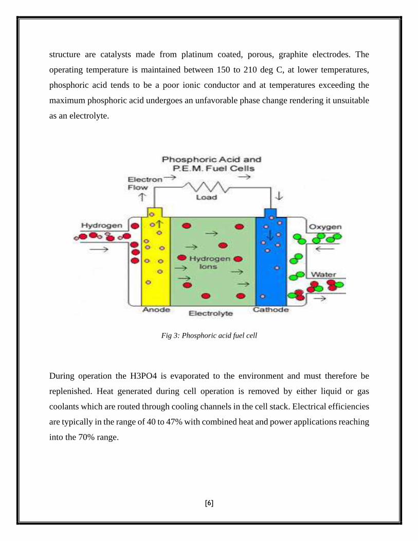
[6]
structure are catalysts made from platinum coated, porous, graphite electrodes. The
operating temperature is maintained between 150 to 210 deg C, at lower temperatures,
phosphoric acid tends to be a poor ionic conductor and at temperatures exceeding the
maximum phosphoric acid undergoes an unfavorable phase change rendering it unsuitable
as an electrolyte.
Fig 3: Phosphoric acid fuel cell
During operation the H3PO4 is evaporated to the environment and must therefore be
replenished. Heat generated during cell operation is removed by either liquid or gas
coolants which are routed through cooling channels in the cell stack. Electrical efficiencies
are typically in the range of 40 to 47% with combined heat and power applications reaching
into the 70% range.
[7]
Chapter-3
MAJOR COMPONETS
A fuel cell system consists of 3 major components
1. A fuel cell stack.
2. A processor to extract pares hydrogen from the fuel source.
3. A storage and conditioners system to adapt the fuel cell’s continuous power only
out to fluctuating demand.
4. A mechanism for recovering heat from electro chemical process.
The reminder of the system consists of pump compressors and controls.
In fuel cell stack, purified hydrogen and oxygen from air pass through linked platter
similar to those in battery. The electro chemical reaction generator electricity and heat. An
energy storage and power conditioners system adapts the fuel cells maximum power flour
to fluctuating power loads. A battery storage system with DC-AC inventor stores power
from low demand periods for use during peak demand.
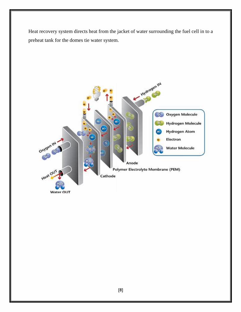
[8]
Heat recovery system directs heat from the jacket of water surrounding the fuel cell in to a
preheat tank for the domes tie water system.

[9]
Chapter-4
DESIGNING of Fuel Cell
Fuel cells come in many varieties; however, they all works in the same general
manner. They are made up of tree segments which are sandwiched together: the anode, the
electrolyte, and the cathode. Two chemical reactions occur at the interferances of the three
different segmens. The net result, and an electric current is created, which can be used to
power electrical devices, normally reffered to as the load.
At the anode a catalyst oxidizes the fuel, usually hydrogen, turning the fuel into a
positively charged ion and a negatively charged electron. The electrolyte is a substances
specifically designed so ions can pass through it, but the electrons cannot. The ions travel
through the electrolyte to the cathode, the ions are reunited with the electrons and the two
react with a third chemical, usually oxygen, to create water or carbon dioxide.
Fig 4: A block diagram of a fuel cell
[10]
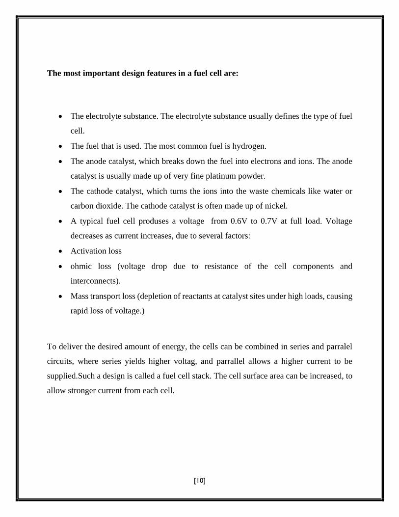
The most important design features in a fuel cell are:
The electrolyte substance. The electrolyte substance usually defines the type of fuel
cell.
The fuel that is used. The most common fuel is hydrogen.
The anode catalyst, which breaks down the fuel into electrons and ions. The anode
catalyst is usually made up of very fine platinum powder.
The cathode catalyst, which turns the ions into the waste chemicals like water or
carbon dioxide. The cathode catalyst is often made up of nickel.
A typical fuel cell produses a voltage from 0.6V to 0.7V at full load. Voltage
decreases as current increases, due to several factors:
Activation loss
ohmic loss (voltage drop due to resistance of the cell components and
interconnects).
Mass transport loss (depletion of reactants at catalyst sites under high loads, causing
rapid loss of voltage.)
To deliver the desired amount of energy, the cells can be combined in series and parralel
circuits, where series yields higher voltag, and parrallel allows a higher current to be
supplied.Such a design is called a fuel cell stack. The cell surface area can be increased, to
allow stronger current from each cell.

[11]
4.1 PROTON EXCHANGE MEMBRANE FUEL CELLS
Fig 5: Proton exchange membrane fuel cell
In the archetypical hydrogen- oxygen PEMFC design, a proton conducting polymer
membrane, (the electrolyte), seperates the anode and cathode sides.S This was called a
“solid polymer electrolyte fuel cell” (SPEFC)in the early 1970s, before the proton
exchange mechanism was well-understood.

[12]
On the anode side, hydrogen diffuses to the anode catalysts where it later dissociates into
protons and electrons. These protons often react with oxidants causing them to become
what is commonly referred to as multi-facilitated proton membranes. The proton conducted
through the membrane to the cathode, but the electrons are forced to travel in external
catalysts, oxygen molecules react with the electrons (which have traveled through the
external circuits) and protons to form water-in this example, the only waste product, either
liquid or vapor.
In addition to this pure hydrogen type, there are hydrocarbon fuels for cells,
including diesel, methanol (see: direct-methanol fuel cells) and chemical hydrides. The
waste products with these types of fuel are carbon dioxide and water.
[13]
Chapter-5
FUEL CELL EFFICIENCY
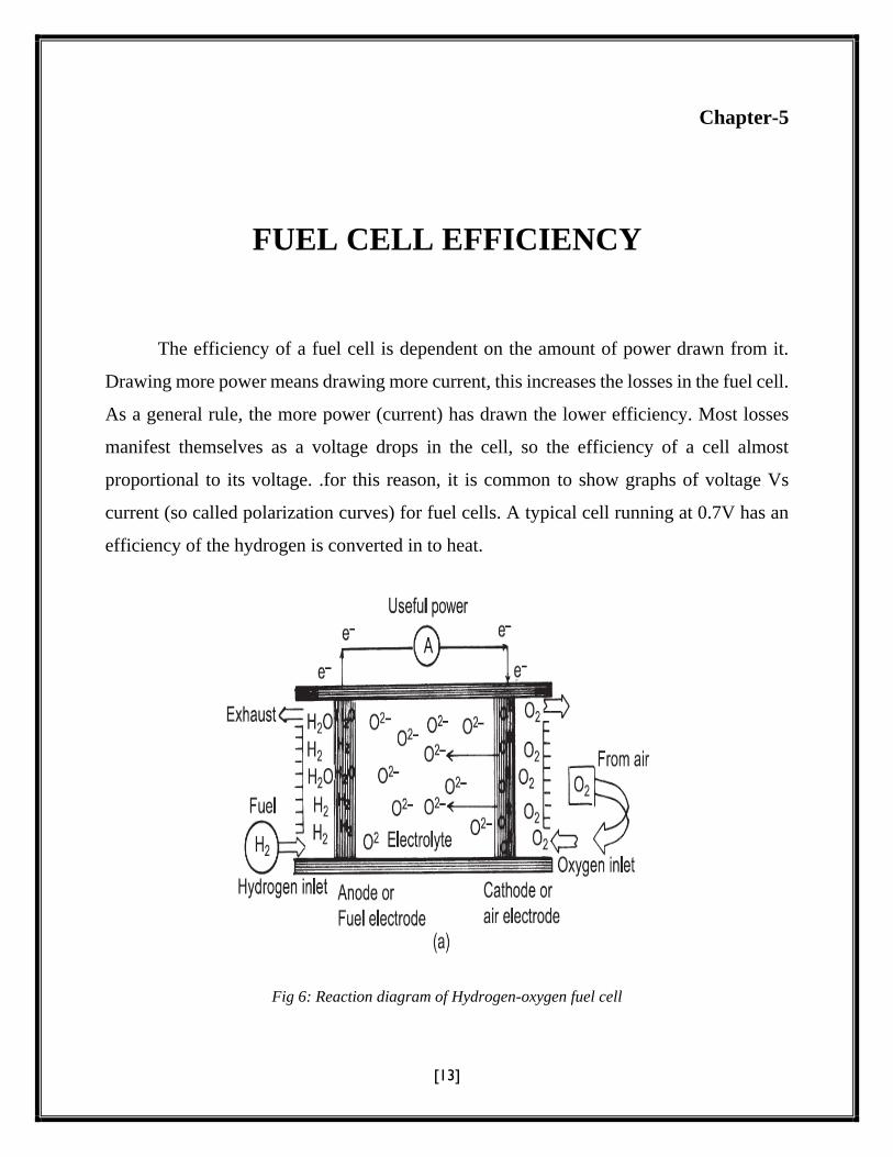
The efficiency of a fuel cell is dependent on the amount of power drawn from it.
Drawing more power means drawing more current, this increases the losses in the fuel cell.
As a general rule, the more power (current) has drawn the lower efficiency. Most losses
manifest themselves as a voltage drops in the cell, so the efficiency of a cell almost
proportional to its voltage. .for this reason, it is common to show graphs of voltage Vs
current (so called polarization curves) for fuel cells. A typical cell running at 0.7V has an
efficiency of the hydrogen is converted in to heat.
Fig 6: Reaction diagram of Hydrogen-oxygen fuel cell
[14]
For a hydrogen cell operating at standard conditions with no reactant leaks, the
efficiency is equal to the cell voltage divided by 1.48V, based on the enthalpy, or heating
value, of the reaction. For the same cell, the second law of efficiency is equal to cell voltage
divided by 1.23V. The difference between these numbers represents the difference between
the reaction’s enthalpy and Gibbs free energy. This difference always appears as heat,
along with any losses in electrical conversion efficiency.
Limited carbon monoxide tolerance of some (non-PEDOT) cathodes.

[15]
APPLICATIONS
Proving power for base stations or sites.
Off-grid power supply.
Distributed generation.
Emergency power systems are type of fuel cell systems, which may include lighting,
generators and other apparatus, to provide backup resources in a crisis or when
regular system fail. They find uses in a wide variety of settings from residential
homes to hospitals, scientific laboratories, data centers, telecommunication
equipment and naval ships.
An uninterrupted power supply (UPS) provides emergency power and depending
on topology, provide line regulation as well to connected equipment by supplying
power from a separate source when utility power is not available. Unlike a stand by
generator, it can provide instant protection from a momentary power interruption.
Base load power plants.
Electric and hybrid vehicles.
Notebook computers for applications where AC charging may not be available for
be available for weeks at a time.
Portable charging docks for small electronics (example: - a belt clip that charges
your cell phone or PDA)
Smart phones with high power consumption due to large displays and additional
features like GPS might be equipped with micro fuel cells.
Small heating appliances.
Space shuttles.

[16]
ADVANTAGES
Fuel cells are clean, highly efficient, scalable power generators that may be fueled
by a variety of fuel feeds stocks and therefore be used in an assortment of power generation
applications. In particular, they offer several advantages over other technologies:
Fuel cells produce electricity without combustion, which means that, unlike
internal combustion, air pollution, or green house gasses and operate at high
efficiencies over a wide range of loads.
Fuel cells, unlike batteries, avoid the need to replace the cell or undergo a lengthy
recharging cycle when its fuel is spent. Additionally, since fuel cells store their fuel
in external storage tanks, the maximum operating range of a fuel cell-powered
device is limited only by the amount of fuel that can be carried.
In distributed power generation applications, fuel cells reduce the load on the need
for the grid and also eliminate (or reduce) the need for over head or underground
transmission lines, which are expensive to install and maintain and result in power
losses/efficiency reductions
Since fuel cells are scalable and can be installed on site, they reduce the need for
large power generation plants (and environmental impacts of such large scale
plants).
Because fuel cells have substantially fever moving parts than internal combustion
engines (ICE), it is anticipated that maintenance costs for fuel cell vehicles will be
lower than those ICE vehicles.
Most fuel cell components are recyclable or reusable.
[17]
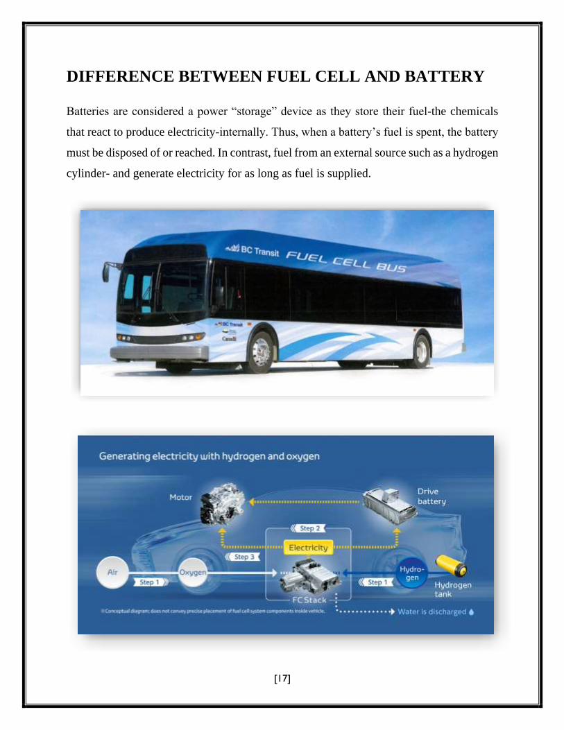
DIFFERENCE BETWEEN FUEL CELL AND BATTERY
Batteries are considered a power “storage” device as they store their fuel-the chemicals
that react to produce electricity-internally. Thus, when a battery’s fuel is spent, the battery
must be disposed of or reached. In contrast, fuel from an external source such as a hydrogen
cylinder- and generate electricity for as long as fuel is supplied.
[18]
CONCLUSION
Fuel cells are an attractive technology option for India, because of their economic,
environmental, and energy management advantages. In India context, they have the
following benefits.
High efficient, can deliver more power per units of fuel consumption.
Least polluting for coal-based power generation.
Low gestation periods due to modularity for setting up new power plants.
No transmission and distribution losses because of dispersed generation.
Suitable for powering vehicles (especially busses) to reduce urban pollution and
diesel import.