fuel and blanket processing development for molten salt
TRANSCRIPT

ii&o* \ OAK RiRGE~ NATlO-NAL CABORATORY opera ted by
UNldh CARBIDE CORPORATION I- ~NUCLEAR DIVISION
for the ;;/ US; Al6MlC ENERGY, COMMISSION
ORNL - W-1652
COPY NO. -z &;‘/
DATE - June 1967
FUEL AND BLANKET PROCESSING DEVELOPMENT?~'* d
. :
Evaluations of Molten Salt Breeder Reactors have pointed ri the direction of desirable design, research, and development
1 for improving the economic and breeding performance of these f systems, In design, the conventional concept of processing
fuel in facilities that are separate from the reactor plant 1 i,
needs to be abandoned in favor of integrating the processing operations directly into.the reactor building. For the MSBR, only a small space-is required adjacent to the reactor cells for processing cells, This arrangement allows significant savings in capital, operating, shipping, and inventory costs.
Research and development have shown that irradiated MSBR fuel can be decontaminated in a four-step process consisting of fluorination, HF6 sorption, vacuum distillation, and reduction-reconstitution, .These operations recover snot only the uranium but also-the-WF-EeF2 carrier, Fluorination and sorption technologies -are welldeveloped for batchwise opera- tion,having advanced through the pilot plant stage..: However, for MSBR application, these-two steps,as well as distillation and reduction-reconstitution,must be developed for continuous operation. These four unit processes are rather simple -and straightforward; however, vacuum distillation requires a higher temperature (~1000~C) than has been encountered previously in molten salt processing.; ~~ Im~
NOTiCEThis document eontains information of a preliminary nature and was prepared primarily for internal use at the Oak Ridge National Laboratory. It is subject to rsvisi&. or correction and therefore does _ not represent a fin01 report.
.

LEGAL NOTICE
This report was prepared OL an DCCOU~+ of Govotnmmt sponsorad work. Neither the United States, nor the Commission, nor my person acting on behotf of the Commission:
A. Maker any warranty or npmsentotion. expressed or implied, with respect to the accuracy, completmorr, or usefulness of the information contained in this report, or that the vs. of any information, apparatus, method, or process disclosed in this repot? may no? infringe
privately owned rights; or 8. Assumer any liobiliti~s with rwpec? to the usa of, or for damages resulting from the use of
any information, opparatvr, method, or process disclosed in this report.
As used tn tha above, *‘person acting on behalf of tha Commission” includes any employee or
cmtroctw of tha Commission, or employ** of such contractor, to ths extent that such employee
or contractor of the Commissim, or employee of such contractor preparer, disseminates, ot provides access to, any information putwant +o his employment w contract with the Commission,
M his l mployman? with such cm+r~~+w.

-3-
! Fertile stream processing steps consist of protactinium removal, fluorination, and m6 sorption. Protactinium removal is singularly important because of the improved breeding performancewithlow protactinium concentrations in the fertile stream. Relatively-high processing rates are required,
Xenon poisoning is kept low by injecting a purge gas directly into the circulating fuel stream. An in-line stripper removes the gases, which are routed to a charcoal system for retention and decay.
This document describes the fuel and blanket processes for the MSRR, giving the current status of the technology and outlining the needed development. It is concluded that the principal needs are to develop the vacuum distillation and protactinium removal operations, which have been demonstrated in the laboratory but not on an engineering scale. A program to develop continuous fluoride volatility, liquid-phase reduction- reconstitution, improved xenon control, and special instrumenta- tion should also be a major developmental effort. An estimate of manpower and cost for developing MSBR fuel and fertile processes indicates that it will require 288 man-years of effort over a 7-year period at a total cost of about $18,000,000.

-4-
TABLE OF CONTENTS
Page NO.
Abstract _-_----------------_--------------------------------------- 1 Introduction -_-c--------------------------------------------------- 6 Elements and Requirements of MSBR Processing ----------------------- 7
Objectives -------------------_------------ -----------------F-- 7 Design Features ----------------------------------------------- 8
Process Operations -------------------------------------------- 8
Description of Process --------------------------------------------- 9 he1 Stream Process _______--_-__----__------------------------ 9
Fertile Stream Process "'c"'c""""-"'""""""" ------ 17
Off-Gas Treatment ---------__----_--_-------------------------- 18 Waste Storage ----------------_-------------------------------- 19
Status of Processing Technology and Needed Development ---i--------- 20 Fluoride Volatifity Process __--------------------------------- 20
Continuous Fluorination --------------------------------------- 25
DF6 Purification by Sorption ---------------------------------- 26
Cold 'leaps ________________________________________------------ 28
Vacuum Distillation ------------------------------------------- 31 Fuel Reconstitution ------------------------------------------- 33 Fuel Clarification -------------------------------------------- 35 Protactinium Removal ------------------------------------------ 36 Waste Handling and Disposal ___________________________________ 36
Process Control ----------------------------------------------- 38 Development of Alternative Processes and Improvements -------------- 39
Iodine Stripping ---------------------------------------------- 39 Use of Additives in Vacuum Distillation ----------------------- 39
Reduction-Coprecipitation and/or Electrolysis ----------------- 40 Ion &change with Nonfluoride Solids ----_--------------------- 41
Schedule of Manpower and Cost for Development Program -------------- 42 Continuous Fluorination -----------_--------------------------- 44 Sorption -------_^----_---------------------------------------- 44 Carrier Salt Distillation and the M3RE Ekperiment ------------- 44

-5- T’ I
u E TABLE OF CONTENTS (cont.)
Page No.
&constitution of Fuel _____c_________c____-------------------- 45
Blanket Processing (Pa) --------------------------------------- 4s Filtration and Salt Cleanup ---_------------_------------------ 46 Process Off-Gas Handling ,,,,,,,-,,---------------------------- 46 Alternative Processing Schemes and Process Improvements ------- 46 Special Instrumentation and Process Control ----------.--------- 47 Waste Handling ad Disposal ----------------------------------- 47
General Design ------------------------------------------------ 47 Salt Production --------------------c___________________------- 48 Engineering Test Unit ---------_------------------------------- 48 Summary of Development Costs --------------------_________c____ 48
References ------------------------------------------------------- -- 49

-6-
INTRODUCTION
The breeding potential of a molten salt reactor operating on the thorium-uranium cycle has been recognized for a number of years, and in 1959 a study was initiated to ccmpare the MSBR on the same bases with other thorium-uranium breeders, namely, aqueous homogeneous, liquid bismuth, and gas-cooled reactors. The comparisons were made on the bases of fuel yield (percent of fissile inventory bred per year) and fuel cycle cost, and the results8 confirmed the belief that the MSBR was attractive in both regards. Evaluations of MSBR concepts have continued toward optimizing nuclear and economic performance and have resulted in the generation of more reliable information on the system. These evaluations have also served to point the direction of desirable development and research.
Whereas the initial studies were made on the bases of (a) on-site and (b) central processing plants using etisting processing techniques, the savings that would result by using an integrated processing plant,>i;e., (a), soon became
E apparent. Furthermore, a new processing concept for recovering the fuel -t?
4 carrier salt by vacuum distillation had been shown by Kelly to be feasible,
considerably enhancing the economic appearance ofthe MSBR. These aspects of the fuel cycle were studied by Scott and Carter' for a 10004~ (elec- trical) system. Protactinium removal from the fertile stream was not considered as a processing step in these studies because no satisfactory process was apparent; however, more recent experiments have suggested a mechanism of protactinium removal, whereby significant improvement in the breeding performance of an MSB can be achieved.
0
These newer design and processing concepts have been incorporated into more recent physics and economic calculations to define an optimum MSBR. The discussion that follows treats processing of MSBR fuel and fertile streams in this same respect. First, processing requirements for an economic molten salt breeder are discussed; second, the process is described; third, the statusofthe technology and needed development for each process step are described; fourth, attractive alternative processes to the main- line operations are discussed; and, finally, a schedule of manpower and
f costs for a developmental program to solve critical MSBR processing problems
and to provide the processes and equipment for the processing plant for an Engineering Test Unit is included,
ELEMENTSANB REQUIREMENTS OFMSBR PROCESSING
One of the most attractive features of a two-region, molten salt reactor is the ease with which the fuel and fertile streams can be processed for removal of fission products and recovery of bred material. The fluid streams are easily removed from and returned to the reactor without disturb- ing operations, and the processing methods are relatively simple and straight- forward, On-site processing is a primary requirement of a breeder reactor, which would be at an extreme disadvantage if a sizable inventory of fissile material were held up in decay cooling and transit.
Objectives
The fuel stream of the MSBR is a mixture of LiF-BeF2-UFk in the approximate molar proportions 63.6-36.2-0.22 mole 5; the fertile stream is a mixture of LiF-BeF2-ThF 4 of approximate composition 71-Z-27 mole $. The primary objective of the fuel process is to recover both uranium and carrier salts sufficiently decontaminated from fission products to ensure attractive breeding performance of the reactor. To discard the carrier salt
with the fission products is not economical since both lithium and beryllium are expensive components.(the former being enriched to about 99.995 at, $ 7LiJ, For the blanket processing, the objective is to remove the bred fissile material on ~a sufficiently rapid cycle to minimize the inventory of fissile material, the fission rate, and concentration of fission products in the blanket salt,. This can be accomplished by removing the 233 U on a relatively fast cycle but even more effectively by removing the protactinium precursor rapidly enough so that its con- centration in the blanket is low. A low 233 Pa concentration is desirable
because each capture of a neutron by an atom of 233 Pa results in the net loss of two neutrons (effectively two atoms of bred 233u) l

Design Features
An essential element in the design of an MSBR processing plant is that of keeping the out-of-reactor inventory low to decrease inventory charges and improve the fuel yield, which is the fraction of fissile inventory bred per year. The logical way to achieve this low inventory is to close-couple the processing plant with the reactor, and it is,pro- posed to integrate the two operations. Processing equipment will be located in cells adjacent to the reactor cell, and a small portion of each circulating stream will be metered semicontinuously to the processing plant. Most processing operations are continuous: the fuel stream being purged of fission products, fortified with makeup fuel and carrier, and returned to the reactor core; the fertile stream being stripped of its ', protactinium and uranium, fortified with makeup thorium and returned to the blanket. It is not necessary to allow long decay periods before processing since the reactants are either gaseous (Fp) or solid (granular NaF) and are not affected by strong radiation fields. Cooling periods before processing no longer than one day and perhaps as low as a few hours should suffice. The length of this period depends upon the design of the continuous fluorinator and the ability to control the fluorination tempera- ture. Removal of fission product decay heat is a principal consideration throughout the plant.
In the integrated plant all services available to the reactor are available to the chemical plant. These include mechanical equipment, compressed gases, heating and ventilating equipment, electricity, shop services, supervision, etc. The cost savings for an integrated facility are immediately apparent when one considers the large amount of duplica- tion required for separate plants. only a relatively small,space is needed for the processing equipment as compared to that needed for the reactor and power conversion equipment so that the additional building cost is small.
Process Cperations
Four major operations are needed to sufficiently decontaminate the fuel stream of an MSBR. These are fluorination, sorption of UF6, vacuum
-f u . I

0 u E
-9-
distillation, and salt reconstitution. The fertile stream requires fluorination, sorption of UF6, and for maximum effectiveness includes '
protactinium removal. These operations represent the most straightforward
processing for achieving a high-performance molten salt breeder. The technology for fluorination and sorption is well developed(through the operation of the fluoride volatility pilot plant at ORNLhthe other opera- tions have been demonstrated in small engineering experiments and/or in the laboratory. The process for each stream is capable of economically
?
c
recovering more than 99.9% of the uranium, 94% or more of the LiF-BeF2 in the fuel carrier, and more than 9% of the LiF in the fertile stream*
DESCRIPTION OF PROCESS
The processing facility must be capable of removing the major portion of the fission products from the molten fuel salt and returning the purified salt to the fuel system after reconstitution with 233 U and carrier salts,
In blanket processing, the facility must recover bred uranium, minimize parasitic neutron loss to protactinium, and minimize the loss of carrier and fertile salts with the waste.
In Fig. 1 a flow diagram is presented to show the steps in processing a molten salt breeder. The flow rates were obtained from physics calcula- tions for a 2225-e (thermal) reference reactor. The core cycle time is 52 days, and the blanket cycle time is about 22 days for the uranium recovery step; protactinium removal is on a l-day cycle. The core power is 2160 Mw (thermal); the blanket power is 65 Mw (thermal). A flowsheet, similar to Fig. 1 and excluding the protactinium removal step, was used in a design.and cost study' of a processing plant for a MOO-I4w (electrical) MSHR.
Fuel Stream Process
Decay Holdup
r'
u F
Irradiated fuel is removed directly frcan the circulating fuel stream for processing, and, as such, is only a few seconds removed from the fission zone. The gross heat generation rate is shown in Fig. 2. It is

F2 TO REcxLE
f I
Uh+F2 SORPTION COLDTRAP
NaF MgF2
Fin RECYCLE
t
I -630 FThAY/REACTOR 4.3FT%WREACl0R 1 I ulallLLAlt
I AHF
NO -S/STATION POWER/REACTOR FUEL wL./REACTOR 9LhNKE.r wL.mEAcIoR @627FT’ U WEMORY/FiEACTOR a 190kg
, ,MW j 1
Pig. 1. Processing Diagram for a Bblten Salt Breeder Reactor.

t
bd P
I I I l l l l l l I I1111111 I I IWll I I111111
JO’3 KY2 IO” loo IO’ IO2 103
TIME AFTER ‘DISCHARGE FROM REACTOR (days)
Fig. 2. Fission Product Decay Heat in MSBR Fuel Stream for 3 1000 Mw (electrical) Reactor. T&e curve is calculated for the gross of fission products in the discharged fuel;
amount

I
- 12 -
necessary to a+w fission products to decay a few hours before fluorination b so that the fluorinating temperature can be controlled at the desired value. This holdup will be carried out in a metering tank in the reactor cell where there is convenient access to the reactor cooling system.
Continuous Fluorination
After the cooling period, the fuel salt flows into the top of a columnar vessel where it is contacted by a countercurrent stream of fluorine gas. The temperature of fluorination is controlled at about 550°C. Uranium tetrafluoride in the irradiated salt reacts quantitatively with fluorine to give volatile lJF6, which is carried overhead by excess fluorine. The chemical reaction is
TJF +F2=UF6. 4 Certain fission product fluorides are also volatile and will leave
the fluorinator with the UF6. The principal metallic elements that form volatile fluorides are ruthenium, niobium, molybdenum, technetium, and
?I
tellurium. Since prefluorination time is so short, appreciable amounts of a fission product iodine and bromine will also be present. These elements are oxidized by fluorine to volatile interhalogen compounds and exit in the UF6 stream. Zirconium fluoride also has a relatively high vapor pressure and has been observed in the overhead product. Sorption techniques are used to purify the UF6 product.
WUl& FWification by Sorption
Volatile fission product fluorides and IJF6 are separated in a series of sorption and desorption steps. These are batch steps, but the process is made continuous by usingparallel beds alternately.
The first separation is made when the gas passes through a bed of pelletieed NaF. The system consists of two distinct zones, one held at 400°C and one at about 1OO“C. In the higher-temperature zone, most of the fission products, corrosion products, and entrained salt are irreversibly removedwhile the UF6 and some fission products pass through to the lower- temperature zone. In this zone, UF6 and MoF6 are sorbed. The barren ($T
fluorine carrier passes through the next bed of pelletized MgF2, which is .

- 13 -
believed to be effective for sorbing technetium; however, available data are not altogether conclusive. The volatile halogens are expected to\pass' through the sorbers and remain in the recycle fluorine stream. These are controlled by decay and by a small gas purge to the off-gas disposal system. About 10% of the circulating fluorine will have to be discarded to purge these fission products.
When the low-temperature zone of the NaF bed is loaded with UF'6, the bed is taken off stream, and the temperature of the cold zone is slowly raised while the bed is swept with fluorine gas. At temperatures around
150°C, molybdenum fluoride desorbs and is carried away, thereby separating it from DF 6' The temperature is raised higher to about 400°C for complete desorption of uranium, which is collected for recycle to the reactor. The NaF and MgF2 beds are reused until. loaded with retained fission products; at this point they are discharged to waste and filled with fresh material. The operation of the sorption system is diagrammed in Fig. 3.
The rate of heat generation by fission products deposited on the sorbers might be as large as 30% of the gross rate shown in Fig. 2. There-
fore, the beds will require cooling to prevent local overheating.
3 Collection
Desorbed UF6 is carried by fluorine into a primary cold trap held at about -40°C where it is collected for the fuel reconstitution step.. The -4O*C trap is backed up by a colder (-60"~) trap to catch any UF6 that might pass through the first trap. For additional safety a NaF chemical trap is included to trap any m6 that might get through the cold traps. When a cold trap is loaded with m6, the trap is warmed to triple point conditions (90°C and 46 @a) to melt m6 and allow it to drain to a receiver for feeding the reduction unit.
Vacuum Distillation
After fluorination, the barren carrier, containing the bulk of the fission products, flows,to a still which is operated at about 1 mm Hg pressure and 1000'C. The LiF and BeF, volatilize, leaving fission products in the still bottoms. This residue &sists largely of rare earth fluorides,

4
F2 AND (Ru, Te, I, Br, MO) FLUORIDES TO GAS SCRUBBER AND/OR
RECYCLE
ORNL DWG 6,3015 114
RECYCLE F2 I
uF* TRAP I
lOD*C DURING SORPTION, 400% DURING DESORPTION
PRIMARY COLD TRAP, -40%
SECONDARY COLD TRAP, -60%
FLUORINATOR + OFF-GAS OR F2 llF, TO
WASTE REDUCTlON UNIT
(Tc)
NaF WASTE @Jb,U
Fig. 3. uF6 Purification System with Disposition of Volatile Fission Products.
\

- 15 - Ir:
u c
which are the principal neutron poisons. Available data indicate that the relative volatilities of the rare earth fluorides, compared to LiF and BeF2, are low and that a good separation can be achieved in a single-step distilla- tion without rectification. The following data (Table 1) have been obtained for several fluoride cckpounds.
Table 1. Relative Volatilities of Rare Earth Fluorides, ZrF
4' and BeF2 With Respect to LiF
Temperature = 1OOO'C Pressure = l$mtnHg
Component Mole Fraction in,Liquid Relative Volatility
LiF 0.842 me
BeF2 0.105 4.6 :: ZrF4 0.0096 1.4
l?t?F 3 0.055 2.5 x 10⁻³ I" N@3 0.06 c3 x 10 -4
=3 0.05 .' <3 x 10 -4
It is proposed to operate the still semicontinuously, allowing the fission products to collect in the still bottoms; the bottoms, in turn, are sent to the fission product accumulator tank (see Fig. 1) for dilution and storage. The accumulator contains about 400 ft3 of 88-12 mole $
- LiF-BeF2 mixture, which is the equilibrium compositionof-theliquid in the still. The accumulator salt is recycled through the still by adding it into the still feed coming from the fluorinator. Since the recycle/feed ratio can have any desired value,.it is adjusted to exercise control over the heat generation rate in the still as the fission products continuously concentrate at that point. Calculations indicate that a volume ratio as low as 1:l is adequate for control of the heat generation.
The 400 ft3 of LiF-BeF2 mixture in the accumulator is believed to be sufficient for collecting fission products for the entire 30-year lifetime of the reactor. At the end of this time the mixture can be processed for
- 16 -
recovery of LiF and BeF 2 and transfer of fission products to some inexpensive medium for permanent disposal.
Although CsF and RbF have higher vapor pressures than I&F and would be expected to contaminate the recycle carrier, no difficulty is expected with these fission products because each has a gaseous precursor which is removed on a very fast cycle in the gas sparging operation. Another fission product that has a relatively high vapor pressure is ZrFb, and it might be necessary to discard a small fraction of the carrier distillate to purge this poison. There is some evidence that the activity of ZrFb is low in the still bottoms; thus, most of the ZrFb will remain in these bottoms. Rven if all the ZrF4 distilled, no more than 5% of the distillate would have to be discarded to control its poisoning effect.
Although fluorination is expected to recover greater than YY.Y$ ,of the uranium in the fuel stream, any small fraction that reaches the vacuum still is not entirely lost. The vapor pressure of UFb at 1000°C is slightly greater than that of LiF allowing part of this uranium to accomparty the carrier salt. f
. Fuel Reconstitution
The principal operation in reconstituting the fuel is to recombine the distillate, the recycle and makeup uranium, and the makeup carrier salt in the proper proportions for feed to the reactor.. Uranium hexa- fluoride from the cold traps is mixedwith a portion of the bred UF6 from the blanket process, and the mixture is dissolved at 550 to 600”~ in recycle fuel salt. The mixture is kept at the proper UFb concentration by introducing LiF-BeF2 distillate and makeup. Hydrogen is then introduced into the mixture to reduce m6 to lJFb. The entire operation can be carried out continuously in a single unit.
A filter after the reduction unit will be used to clarify the fuel salt before it goes to the reactor. Reducing conditions in the column will precipitate any colloidal nickel or iron,:which will contaminate the salt (as a result of equipment corrosion).

3 --17 -
w t
Xenon Removal
Because of the low solubility of the rare gases in molten fluoride salts, xenon can be stripped from the fuel salt by sparging with an inert gas such as helium or nitrogen. The sparging is done in an in-line gas
stripping unit located between the pump and the reactor. 13 A very short cycle time of the order of 30 ~sec is required to keep xenon poisoning at the desired low level, which is less than 0.5% fractional poisoning. The inert carrier gas transports the fission gases to charcoal adsorbers where they are retained for decay; the carrier gas is recycled. Because of the very short cycle time, this processing must be accomplished with equipment in the reactor primary system and is considered to be a part of the reactor system, rather than a part of the fuel processing system.
+
An alternative method of eliminating xenon is to process-the reactor fluid for removal of iodine, the precursor of xenon. A methodforremoving iodine has not been developed; however, laboratory experiments have given promising results. l1 The method is to sparge the fuel salt with an W-H2 mixture,allowing the iodine ion (the form present under reactor conditions)
P
f w c
to react with HF forming HI, which is removed as a gas. Considering the fact that 135 I has a half-life of 6.7 hr, it is seen that the processing rate must be fast to maketheprocess effective for removing the xenon daughter. There is a lower limit to the amount of 13'Xe that can be purged
by removing the iodine precursor; the independent fission yield of 135Xe is
quite significant (removing 135 I accounts for only about 805% of the xenon poisoning).
Fertile Stream Process
The fertile (or blanket) stream process has three primary operations: -protactinium removal, continuous fluorination, and m6 sorption. The
assumption is made that the uranium is not removed with the protactinium, so the latter two operations are- analogous to the corresponding fuel stream operations discussed above~but are.carried out at a higher volumetric rate. The fertile stream is cycled through fluorination once~every 20 to 25 days to keep a low uranium concentration in the blanket, thereby keeping the

- 18 -
fission rate low. The low fission rate ensures a low fission product u *
accumulation rate so that it is unnecessary to remove them on the same cycle as uranium, In fact, a 30-year discard cycle ofthe barren fertile stream is a sufficient purge rate for fission products. At the end of .
this time the waste tank would be processed to recover ThFh; the fission products would be permanently stored in an inexpensive medium.
If the process for removing protactinium from the fertile stream also removes all the uranium, fluorination of the fertile stream will not be necessary. A fluorination step is, however, required in the subsequent processing of the protactinium to separate the uranium.
The bred uranium is recovered in cold traps as IF6. A portion of this is used to refuel the core, and the remainder is sold.
Protactinium Removal
The breeding performance of the reactor can be significantly improved if the protactinium concentration is kept low. The proposed process is to contact the fertile salt at about 650°C on a rather fast cycle, perhaps as fast as once every 10 to 60 hr, with a stream of liquid metal carrier; e,g., bismuth, containing 3000 to ho00 ppm thorium. The thorium metal-reduces protactinium and the two nuclides exchange between the two streams. A hydrofluorination or sorption treatment is then used to extract protactinium from the bismuth stream into a second salt mixture,in which it is allowed to decay to uranium. Later the salt is fluorinated to recover the uranium.
Preliminary data indicate that 96% of the protactinium can be removed from the blanket by this method. The behavior of uranium has not yet been determined. Thorium, of course, is the ideal reductant because the removed protactinium is replaced w equivalent fertile material.
Off-Gas Treatment
Most of the off-gas from the processing plant comes from the continuous fluorinators; smaller amounts are formed in various other process vessels. The gases are treated to prevent the release of any contained fission products to the atmosphere. Excess fluorine used in the fluorinators is-
,-- v‘
a

- 19 - P
recycled through a surge chamber, and a small side-stream of the recycling fluorine is sent through a caustic scrubber to prevent gross buildup of fission products. Each of the processing vessels and holdup tanks has off-
gas lines that lead to the scrubber for removing HF, F2, and volatile contaminants.
The scrubber operates Asia continuous countercurrent, packed bed unit with recirculating aqueous KOH. A small side-stream of KOH solution is sent to waste, and the scrubber off-gas is contacted with steam to hydrolize fission product tellurium. A filter removes the hydrolized product. Non- condensable gases are sent to the facility that treats gases generated by the reactor; ultimately the gases are discharged to the atmosphere after considerable dilution.
Waste Storage
Waste streams from the processing facility are: (1) aqueous waste from the KOH scrubber for purifying recycle fluorine, (2) molten salt from fertile stream discard, (3) NaF and MgF2 sorbent from UF6 purification, (4) daughter products of Kr and Xe that accumulate as solids in the gas sparging system of the reactor, and (s), if needed, molten salt discard of LiF-BeF2 carrier to purge ZrF4. The material in the fission product accumulator (see Fig. 1) is not considered a waste because it is not removed from the process even though it contains fission products. Eventually a portion of this volume becomes waste at the end of the reactor lifetime and after processing to
reclaim as much as possible ~of the LiF-BeF2 content, Each of the waste
streams would be stored in underground facilities at the reactor site; after appropriate decay periods and waste treatment procedures, these could be sent to permanent storage or.disposal sites.
Aqueous Waste
The aqueous waste stream is small and would be combined with similar wastes from the reactor in a single underground facility.

- 20 -
Fertile Stream Discard
This waste is stored in an underground tank which can be cooled by air circulation in natural convection. The specific heat generation rate is low because of the small concentration of fission products present. It
may be desirable to store the fertile stream discard inside the processing cell. The salt volume is only about 2500 ft3, and, if inside the cell, cooling could be conveniently provided by the same medium that is used in the processing operations.
NaF and HgF2 Pellets
These sorbents, which contain the volatile fission product fluorides, are stored in cylindrical cans in an underground concrete vault, The spent pellets are discharged fram the sorbers into cans inside the processing cell. When several cans have been filled,.the contents are moved from the cell to the vault." Decay heat is removed by forced.air circulation through the vault.
Kr and Xe Daughter Products
Krypton and xenon, sparged from the reactor, are precursors of solid fission products (Rb, Sr, Y, Zr, Cs, Da, La, Ce) that settle as fines and dust throughout the gas processing system. These particulates must be :, removed to avoid clogging and overheating gas lines. A possible method for doing this is to periodically flush lines and gas holders with a molten salt, which dissolves and accumulates the decay products. The accumulator could be a vessel,@n the processing cell)in which these fission products are retained until permanent disposal.
Fluoride Volatility Process
Rxperience at CRNL with the processing of molten salt fuels by the fluoride volatility process dates from 1954 and included all phases of laboratory and development work through the successful operation of a

pilot plant. During this period the process was adapted for use with the fluid fuel, NaF-ZrFL-UFb, of the Aircraft Reactor Experiment, and two alloy fuels, Zr-U and Al-U. Although the alloy fuels were solid, they were dissolved in the molten fluoride salt and their processing was carried out by methods analogous-to processing a molten fluoride fuel. After the initial dissolution step for the solid element, processing of liquid and solid fuels becomes identical within the limits imposed by different compositions.
The fluoride volatility process takes'its name from the principal operation, the volatilizing of uranium as the hexafluoride. The advantages
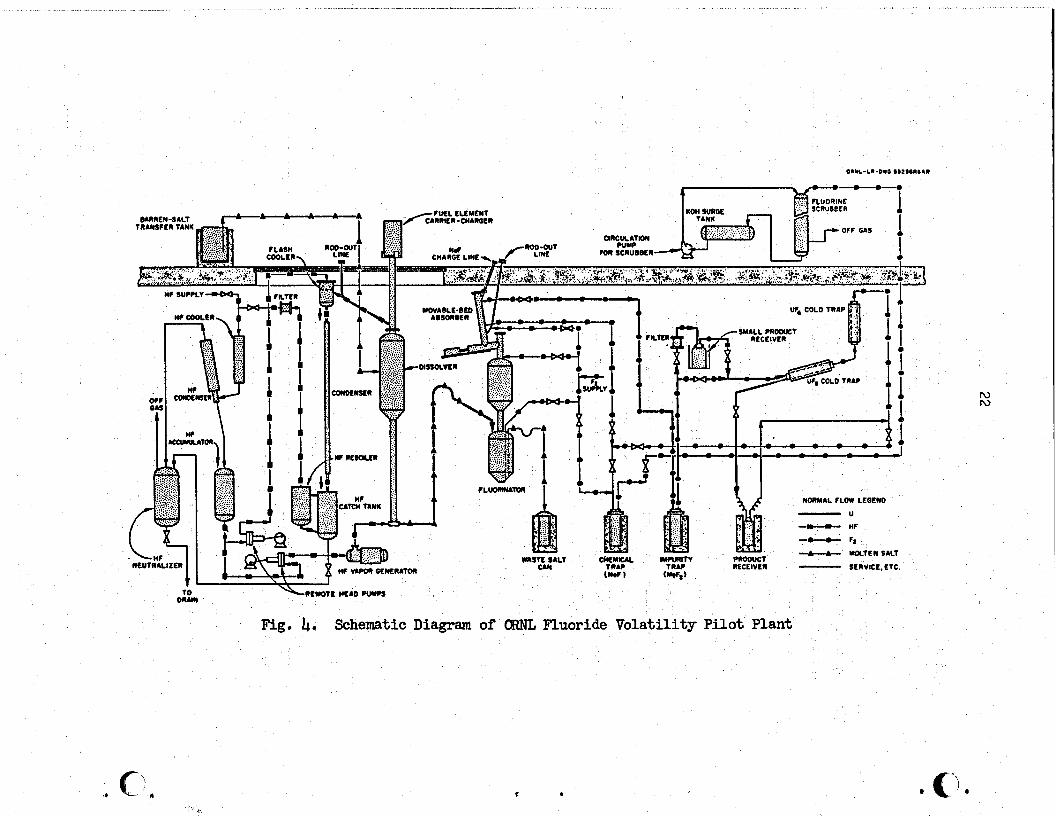
of fluoride volatility are: thesmall volume of fission product waste, the convenient form of the IJF6 product, which is easily converted to UF 4 for fuel recycle, the virtual elimination of processing criticality hazards as opposed to aqueous processing-of enriched fuels, andthe.high decontamina- tion factors attainable for the IJF6 product. Unattractive features of the processare: the corrosiveness of fluorine-molten salt mixtures, and, to a lesser degree, the high processing temperatures. A diagram of the CRNL Fluoride Volatility Pilot Plant is shown in Fig. 4.
In addition to the molten fluoride processing work at CRNL, similar research has been carried out at Argonne National Laboratory, Efforts at the two installations were ccmplementary,with‘the ANL work being directed primarily toward hydrofluorination and fluorination techniques and reagents as well as equipment development. In addition, molten salt process develop- ment was supplemented by an extensive corrosion-testing program under sub- contract with Battelle Memorial Institute (1959-1963). Evaluations were made of potential construction materials for the hydrofluorination and fluorination equipment; the metals of most interest were found to be Hastelloy N, Alloy 79-h (knownalso as HyMu 80 and-Moly Permaloy), and Nickel 201 (L-Nickel). All these metals are satisfactory construction materials for molten sa.lt processing equipment with the possible exception of the vacuum still. The 1000°C distillation temperature is beyond the range at which materials have been evaluated.,
The proposed process for the MSHR includes several operations in addition to those with which there has been reprocessing experience. The most important of theseare: *continuous fluorination, vacuum tistillation,
4’ and removal of protactinium from the fertile reduction of UF6 to TJF
.- - nOLO tNA?
‘. WDNYIL FLOW UDCND
1’
-u -- nF
- - F, b-F.
rmmJc1 -cc UDLlENSALt
CAN MCEIVLN - (Nub WV*)
SEnVICL. E TC.
Fig. 4. Schematic Diagram of ORNL Fluoride Volatility Pilot Plant
c .

- 23 -
stream. The following paragraphs review the experience with ARE, Zr-U, i and Al-U fuel processing and delineate the status of existing technology
for the operations involved in MSER processing.
ARE Fuel Processing
Initial development of a process for molten fluoride fuel was motivated by the need to recover unburned, highly enriched uranium from the irradiated fuel of the Aircraft Reactor Experiment. This fuel was a 48-49.52.5 mole $ mixture of NaF-ZrF4-UF4. Beginning in 19% the fluoride volatility process was developed for this recovery and culminated in successfully processing the ARE fuel during the period December 1957 to March 1958. Since,the reactor operated in November 1954, the irradiated fuel was about three years old. The recovery operations consisted of batchwise UF6 volatilization, followed by its decontamination on granular beds of sodium fluoride, and its recovery in cold traps. Barren waste, containing the bulk of the fission
; products, was drained into metal cans and buried. Better than 99% recovery of uranium was attained in this initial hot operation of the fluoride volatility pilot plant. Decontamination factors of at least 10 4 were I attained,as indicated by the gross garmna activity of the.product. 9
Zr-U and Al-U Fuels
In the initial stages of fluoride volatility development it was recognized that the process had application to fuels other than molten fluoride salts. Concurrentlywith the development of a process for ARE fuel, laboratory research was pursued toward adapting the process for treating irradiated Zircaloy-clad, Zr-U alloy fuel from submarine reactors. This~research resulted in the development of a hydrofluorination operation in which the solid fuel element is dissolved by reaction with anhydrous HF in molten LiF-NaF-ZrF 4; then-remaining steps of the process were the same as for ARE fuel.
Processing experience led to improvements in the pilot plant and equipment before operation with Zr-U fuel. In addition to the hydro-
; fluorinator, an improved fluorinator (Fig. 5) and NaF sorber were incor-
u porated in the modified plant. The plant was operated with irradiated a‘

24
ORNL-LR-DWG 39150-R2
SAMPLE LINE (I-in NPS SCH. 40)
TUBULAR EL . .------ -EC HEATERS
CORROSION-SPECIMEN NOZZLE (6) H
FURNACE LINER -
TREPANNED SECTION (4.in. 00)
DRAFT TUBE -
WASTE-SALT OU
MATERIAL I ,-in. NICKEL 2Olj
:T OUTLET TO .E BED ABSORBER
SOLIDS SETTLING CHAMBER
VESSEL SUPPORT
APPED NOZZLE -\
THERMOCOUPLE
&jj FLUOF
J
FURNACE
/FLUORINATION CHAMBER ( 16-in. 00 1
3INE iNLET
-TREPiI&f’J~DO~~CTION
0 .!5 16 15 20 INCHES
Fig. 5. Volatility Pilot Plant Fluorinator Vessel e /--.

i
- 25 -
submarine reactor fuels during the period March 1962 to September 1963. Fuel elements that had cooled as long as 6.5 years and as short as 6 months were successfully processed, Uranium recovery and decontamina- tion in all runs were excellent.
The final phase of operation of the ORNL Volatility Pilot Plant was associated with processing aluminum-clad, Al-U alloy fuel, 10 It was found that the solid elements could be satisfactorily dissolved by reaction with anhydrous HF in molten 66-22-12 mole 5 KF-ZrF -AlF 4 3’
Other operations in the process were the same as for Zr-U alloy processing, and the same pilot plant equipment was used. A number of pilot plant runs were made with irradiated Al-U fuel during the period July 1964 to January 1965 at which time the Volatility Pilot Plant was shut down. During that period, Al-U fuel cooled for only four weeks was satisfactorily processed. The same excellent recovery and decontamination factors were obtained as with ARE and~Zr-U fuels; uranium recoveries of 99.9% or better,and decontamination factors of lO',were typicall
Continuous Fluorination
Continuous fluorination is desirable for processing both the core and blanket of an MSBR because of the need to minimize the out-of-reactor inventory and the costs of processing. Engineering development is compli- cated by the corrosiveness of the molten-salt-fluorine mixture and by the difficulty of reproducing in the laboratory the high internal heat generation rate of a recently irradiated fuel.
Current Status
~!Che technology for batchwise fluorination has been rather thoroughly developed and applied in the Fluoride Volatility Pilot-Plant but there is little experience with continuous fluorination. Qle technique of continuous fluorination involves spraying or jetting mall droplets of molten salt through a fluorine atmosphere in such a way that they do not contact the metal walls of the fluorinator, Some very preliminary-tests* with single salt droplets have been successful in achieving high uranium recovery.

- 26 -
A second method, which appears to be the most promising, is to carry out the fluorination in a liquid-phase continuous system using.a l/2- to 3flr-in.-thick layer of frozen salt to protect the vessel walls. The initial work on such a system was done at Argonne National Laborz+tory;3 currently, the development is being pursued in the Chemical Technology Division at C%UJL. Preliminary results, employing units that did not have frozen-wall protection, have demonstrated that high uranium recoveries can be effected in continuous, countercurrent operation.
Needed Development
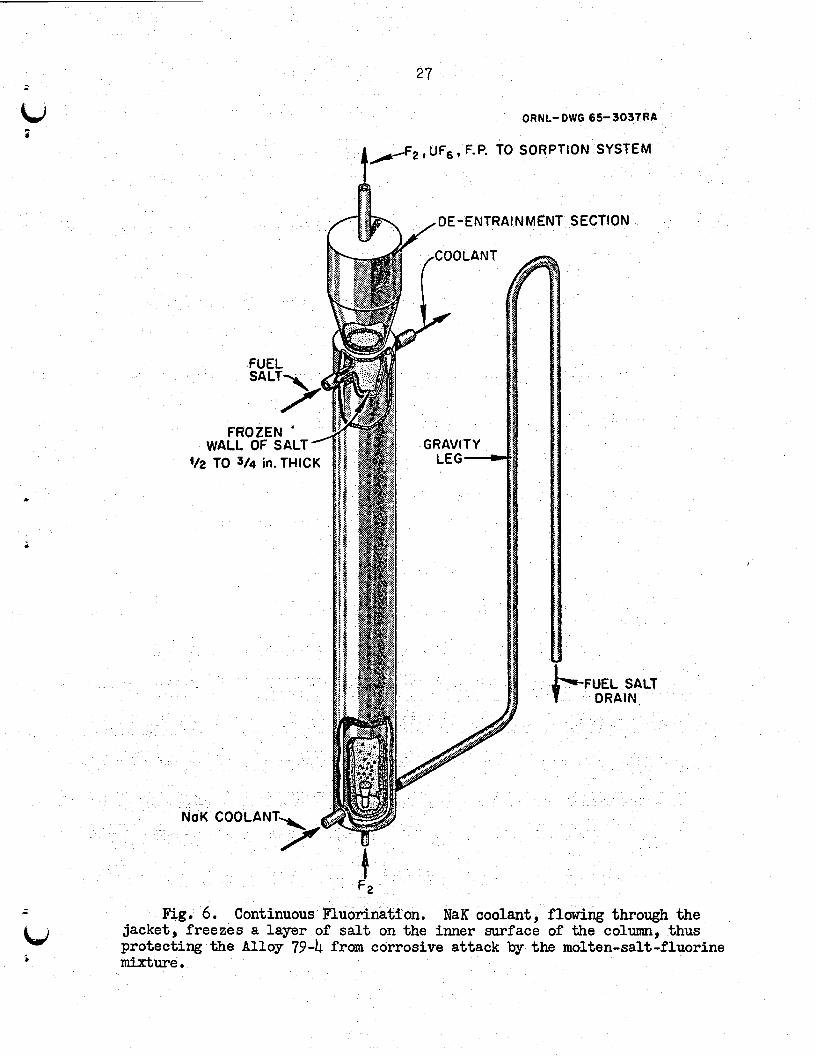
Engineering development of a continuous fluorinator should be given high priority. Areas requiring study include: mass transfer information; process flow control; method of establishing and maintaining a frozen-salt wall; mist deentrainment in gas stream; and, efficiency of gas-liquid contact. A problem in particular,need of attention is the design of nozzles that admit and remove the molten salt and fluorine gas. It might be difficult to protect these areas from corrosive attack by establishing a frozen-salt wall. In the development it should be recognized that there is a large difference in capacity between the fuel and fertile stream fluorinators and that the internal heat generation in the fertile stream is appreciably less than in the fuel. A conceptual design of a continuous fluorinator is shown in Fig. 6.
UF6 Purification by Sorption
The NaF and MgF2 sorption units provide adequate decontamination for
%' The batchwise units can be operated satisfactorily for both.fuel and fertile streams of the MSER. Development on this part of 'theprocess is not critical to successful operation of a molten salt breeder experiment.
Current Status
The UF6 purification system has been operated as an integral part of the Fluoride Volatility Pilot Plant,producing a product that can be handled directly. Also,it has been demonstrated that uranium recovery from the sorbers is essentially quantitative.
27
ORNL- OWG 6S- 3037RA
t
/a-F2 t UF6 t F.P. i0 SORPTION SYSTEM
-
DE-ENTRAINMENT SECTION
112 TO 314 in. THICK
FUEL SAL
NaK COOLANT\
/
Fig. 6. Continuous Fluorination. NaK coolant, flowing through the jacket, freezes a layer of salt on the inner surface of the column, thus protecting the Alloy 79-k from corrosive attack by the molten-salt-fluorine mixture.

- 28 -
Needed Development
Although no extensive development is needed to ensure successful operaWon of the sorption system, there are several areas in which performance data should be obtained. The sorption characteristics and capacity of MgF2 for technetium are not well known; the methods for removal of tellurium and ruthenium are also not well known; and the chemistry of molybdenum in the sorption system needs better definition. From an engineering viewpoint, a sorption system that could be operated continuously would have advantages over a batch system, and such a system should be developed for large-scale MGHH installations.
Heat generation in the sorber beds will be appreciable because of the short decay time before fluorination. A thorough evaluation must be made of this problem gncluding a satisfactory cooling mechanism). Since the sorbents become wastes that are removed from the processing cell for storage, it is essential that a means of doing this be developed (one that precludes frequent entry into the cell),.
A diagram of a successfully operated unit is shown in Fig. 7.
Cold Traps
Current Status
Cold traps, like the one shown in Fig. 8, have been used at ORNL and OHGDP for the collection of DF6. The unit has to be operated batchwise, but this is no deterrent to its use in a breeder experiment or a full-scale installation.
Needed Development
No development is needed on this phase of the process on a near-term basis; however, ultimately it will be desirable to have a continuous cold trap system.

29
NaF CHARGING CHUTE
our%-LR-DWG 504MR-3
1 (/,-in. NPS, SCHED-40 (AIR GOOL- ING AND THERMOCOUPLES )
I SCHED-40 INCONEL
WASTE RECEIVER
/ r INCONEL-X PISTON
S-in NPS, SCtiED-80 lNCONEi
HYDRAULIC CYLINDER 7
Ftig. 7. Movable-Bed Temperature-Zoned Absorber. When the lower zone of the bed becomes loaded with fission products, the hydraulic cylinder operates the piston to discharge that portion of the bed into the waste carrier. Fresh NaF is added at the top. This apparatus has already been tested in the CHENL pilot plant.

30
ORNL-LR-DWG 19091 R-l
/ THERMOCOUPLE /d%h w
CALRor “---I-.- ‘*’ J nmuLn3 w -n 34
---. a I. . SCALt Un.1
INLET END HEATER
L REFRIGERANT TUBES (4)
15-in.-SPS COPPER PIPE
Fig. 8. Cold Trap for m6 Collection. This design has already been successfully used in the CENL pilot plant.

- 31 - ;
Vacuum Distillation
The vacuum distillation concept for separating LiF-BeF2 fuel carrier from fission products is feasible from an engineering viewpoint. However, considerable development is needed to perfect the operation for a breeder experiment, and the most significant advancement in molten salt processing can be made by developing vacuum distillation.
Current Status
Research has only recently begun to explore vacuum distillation of molten salts, and a high priority should be given to this critical step in the processing scheme. Although a considerable amount of physical and chemical data for this system has been measured, more data, especially relative volatility, activity, and distillation rate measurements,, are needed before a full-scale plant unit can be designed. It appears that semicontinuous operation of the still as diagrammed in Fig. 1 is the most satisfactory methodforaccumulating and storing the fission products. The general problems and technology of operating a piece of equipment at 1000°C and 1 mm Hg need to be determined so that their influence on design canbe recognized. Extensive, nonradioactive testing of the MSRE experimental still should answer some of these questions.
Vacuum distillation has been seriously considered for purifying the 4 carrier since laboratory tests showed that decontamination factors for
rare earths in the range 100 to 1000 could be achieved. These bench-scale tests have been continued to develop basic data for the relative volatility (see Table 1) of rare earth fluorides as well as operating technology at high temperature and low pressure. Also underway is the fabrication of a I large-scale distillation experiment that will be an extensive demonstration of the operation employing nonradioactive mixtures; the last part of the experiment will be a demonstration run employing radioactive spent fuel from the MSRE. The equipment for this experiment is shown in Fig. 9.
Needed Development
i

I
EONTAMINATQ Fm- LIF - 65.6 mole % BaF2 u29.4 ’ 6 nF4 m 5.0 l l
FISSION PRODUCTS
ORNL OW6 66-10962Rl
VENT
t
-c OECONTAMINATED LIF - BrF2- Lrfe
Fig. 9. Vacuum Still for MSRE Distillation Experiment. Contaminated feed is fed continuously to the annular space in the still by pressurizing the feed tank with argon. The feed rate is made equal to the vaporization rate so that the still level remains constant. The course of the distilla- tion is followed by periodic sampling of the condensate. The bulk of the fission products remains in the still residue.
. c ”

- 33 -
Even though the accumulated fission products generate a considerable amount of heat, the use of the accumulator vessel lowers the specific heat generation rate to a value that introduces no difficulty in designing the heat removal system. The calculated magnitude of this heat generation rate for a conceptual still design for a 1000~Mw (electrical) MSER is shown in Fig. 10.
The 1000°C operating temperature of the vacuum still introduces metallurgical problems that have not been encountered previously in molten' salt processing. Equipment for the MSHE distillation experiment is made of Hastelloy N; however, it is believed that this material is not the best for these conditions and that development of a suitable material should be started. Molybdenum or a high molybdenum alloy are likely candidates and should be evaluated. Not only must the material be compatible with molten fluoride salt but also with the coolant, which will probably be NaK or another molten salt, and the surrounding atmosphere. Duplex or clad material may be applicable.
Fuel Reconstitution
The reduction of UK6 to IJ'Fb and recombination of the mb with LiF-HeF2 carrier requires engineering development. This work should have a high priority, ranking in importance with continuous fluorination and vacuum distillation.
Current Status
The reduction of UF6~by hydrogen in an H2-F2 flame is a well known reaction; the reductionis rapid and quantitative. However, the powdery Wb product is difficult to handle remotely. Liquid-phase reduction in which UF 6 is reacted with H 2 in molten salt is more suitable for continuous, trouble-free operation. A limited amount of wor d has been done on liquid- phase reduction, and the data indicate that the method is highly suitable to this application.

10
10-l
34 ?
CI c
ORNL DWG 674268
I I
5
1.0 10 10'
OPERATING TIME OF VACUUM STILL (duys)
Fig. 10. Heat Generation Rate in the Vacuum Still Residue Due to Fission Product Buildup. The integrated heat generation rate of decaying fission products in the still residue makes it necessary to accumulate these nuclides in a relatively large volume in order to lower the specific heat generation rate. The above curve is for gross amounts of fission products from processing 1s fi?/day of fuel from a 1000 Mw (electrical) reactor system. Elapsed time between discharge from the reactor and entry to the still is 2.58 days.

Needed Development
- 35 -
Little is known about the kinetics of the absorption and reduction of UF6 in the molten fluoride mixture other than that it is fast. The mechanimn may be reaction of UF6 with'~DF 4
to form an intermediate fluoride,followed by reduction with HZ'. An experimental program is needed to study reaction rates, temperature, DF4 concentration, nozzle design, contactor design, and gas-liquid separation. There might be a corrosion problem in the reduction unit, and considerable attention will be needed in the designof theunit to minimize this effect.
Fuel Clarification
: Reducing conditions that exist in the TJF6 reduction unit are conducive
to the formation of metallic species, particularly nickel and iron, which may be in a finely divided or colloidal state. Before returning to the reactor, the fuel will need clarification. Development of a solid-liquid separation system for the breeder experiment is not a critical item; however, it is a problem that will have to be solved eventually.
Current Status
Final clarification of the fuel charge for the MSRE was accomplished by filtration, which was carried out after an HZ-HF treatment to reduce oxides. Sintered nickel filters were used in a batch operation, and after use the filters were discarded. This procedure was very effective in clarifying the molten salt.
Needed Developer&
So far, filtrations have ~been carried out on nonirradiated salts, and one did not have to cope with-heat generation from fission product decay on the filters. This could be a real problem in a system that recycles fuel. Present filters probably do not have an adequate operating lifetime in.this type of service. No techniquesfor handling or backwashing the filter'cake have been worked out. A continuous clarification method would be highly desirable to avoid frequent entries into the cell to change filters.

Protactinium Removal
Protactinium removal is an important operation in fertile stream processing and should be vigorously pursued. The benefits are primarily in improvement in the breeding ratio b decreasing parasitic capturesjand reduction in the thorium inventory. In order to be effective, the process- ing rate for protactinium removal must be significantly faster than its natural decay rate (half-life = 27.4 days); this requirement means a high volumetric processing rate for the fertile salt.
Current Status
The work on protactinium removal has been confined to laboratory development, which has given some premising preliminary results. The status of this work is discussed in the report 12 on the chemical develop- ment program, CRNL-~~-1853.
Needed Development
Laboratory investigations into protactinium removal are underway, but no engineering development has been started. As soon as the laboratory work has reached the point at which engineering studies can be useful, the studies should be started. They will involve the complete engineering development of process and equipment. A primary need for the engineering is an alpha-handling facility in which to do the work. Building such a facility should begin soon in order to be ready when needed. Engineering development must be oriented toward a simple and easily operated process because of the high volumetric throughput required to maintain a low protactinium concentration.
Waste Handling andDisposal
Waste handling for an MSDR poses some problems that have not been encountered before in processing operations. These are brought about primarily by having considerable amounts of fission products appear at several points in the process, for example, in still bottoms, in NaF and

- 37 -
taJ f
MgF2 sorbents, and.throughout the gas sparging system. In-process collection and handling of these wastes are areas that need study and development. On the other hand,waste disposal is not a critical problem in the development of a molten salt breeder experiment. Bulk storage procedures like those used for aqueous wastes can be used for the near term while research and development effort is applied in more-critical areas.
Current Status
The general topic of waste disposal has been the subject of consider- able study at CRNL for several years. Although molten fluoride wastes were not a specific part of the study, a large amount of the developed data and knowledge are applicable in this case. For example, the cost data for permanent disposal and,heat dissipation rate in underground storage facilities should be very good estimates for the fluoride salt case. In addition there is considerable experience in'handlingand treating hot aqueous wastes in pilot plant operations at Hanford and the Idaho Chemical Processing Plant to make glasses and calcined products.
Needed Development
A study is being made of waste disposal for molten fluoride salts to determine the most satisfactory program to follow. The fission product accumulator, which is integrated directly into the vacuum distillation
step, is in effect a waste tank that stores the bulk of the MSER waste for its 30-year lifetime. At the end of life and following an interim cooling period, this waste could be disposed of by procedures current at that time. Another highly radioactive waste is the NaF and "gF2 sorbent from purifying the UF&. Since this material is already in solid, granular form, it is probably suitable for permanent disposal if sealed in the proper container. An interim cooling period would of course be necessary.
fn the reactor off-gas ~treating system, however, fission products are not conveniently collected in a'material that subsequently acts as a retentionmedium; instead decaying krypton and xenon deposit 'solid daughter products, perhaps as fines and dust, throughout the off-gas system. The

- 38 -
problem of keeping the off-gas system clean of such products has not been encountered in fuel processing, and considerable development is needed to perfect a satisfactory method.
Process Control
;;;
*
The chemical processing plant will need measurements of radiation, temperature, pressure, uranium concentration, and flow rate. Development of a flow metering device is of outstanding importance because of the proposed continuous operations, and the work should be undertaken in the near future.
Current Status
All of these measurements have been encountered in the development program for the MSRE and much satisfactory instrumentation has been developed. In the case of temperature and pressure control, satisfactory means of control have been developed. However, the problem of controlling the flow
T
rate of a molten salt stream has not been solved. There is no current method of continuously measuring uranium concentration in's flowing stream of molten salt or UE 6 concentration in a flowing gas stream- Concentrations have been determined by sampling and laboratory analysis.
Needed Development
The primary need in instrumentation for processing the MSDR is a flow control device that can meter the flow of a molten salt stream. The problem has been recognized as a difficult one and, in the past, has been circum- vented by batch operation and liquid level measurements. However, for snooth operation of a continuous process, such a device will be needed. The usual method of using flow control valves is not suitable for a molten salt and has been avoided.
Considerable emphasis must also be placed on the development of in-line instrumentation for concentration measurements, particularly for uranium, lithium, and beryllium. Smooth operation of the plant might require a fast analysis of a flowing stream.

- 39 -
f4d DEVELOPMENT C4F ALTERNATIVE PROCESSES AND IMPROVEMENTS f
The discussion in the preceding sections has presented the main-line effort for the development of a processing method for the molten salt breeder reactor. In this section several alternative schemes are described. These schemes have promise for improving or substituting for the primary processing method and a concurrent investigation should be conducted.
Iodine Stripping
No single fission product has such a deleterious effect on the breeding usXe performance as . Removal of its iodine precursor from a side stream is
13%e has a direct an indirect means of removing xenon; however, since fission yield, the reduction in poison fraction by iodine removal is limited. Iodine .&ripping does not appear to have an advantage over direct stripping of xenon, and‘development should be subordinate to more important problems.
i
Current Status i
Some laboratory studies have been made of the chemistry of iodine in molten salts. They included experiments in which iodine was removed from salt by sparging with a stream of RF in hydrogen.
Needed Development
Laboratory development should be continued to obtain the basic data for an iodine removal process. Engineering support is also needed to evaluate proposed processes. The engineering effort will include some experimentation as well as process analysis and calculations. Fission
gases contain a surprisingly large amount of the decay energy of the system, and the importance of this fact needs to be assessed in the design of a fission gas disposal system.
Use of~Additives in Vacuum Distillation
The success of vacuum distillation depends upon the fission product fluorides' having a low relative volatility compared to LiF, and extant

- 40 -
data indicate that this is the case with the rare earths (see Table 1). However, there is a possibility that even-lower relative volatilities can be achieved through the use of additives that react with the rare earths, zirconium, and other fission products. The additives could be introduced just prior to the vacuum distillation step and would remain in the still residue, being sent to waste when the still is drained.
This technique could be significantly helpful in improving zirconium decontamination if the proper complexing additive were found. Zirconium fluoride is more volatile than LiF so the vacuum still may not be very effective in separating it from the carrier unless its activity in the solution is lowered. Zirconium poisoning can be economically controlled by discarding carrier salt, but lowering ZrF4 volatility would decrease the required amount of carrier discard.
Current Status
No work has been done. S
Needed Development
Reliable relative volatility data for the rare earths and zirconium fluorides are being obtained, and this is the first step in accurately assessing the effect of additives. Bench-scale development isthe primary need. If useful additives are found their effects can be demonstrated in the general development of the distillation process.
Reduction-Coprecipitation and/or Electrolysis
Reductive coprecipitation6 of the lanthanide elements with beryllium has been demonstrated in the laboratory. The reduction product is a refractory, insoluble beryllide deposited at the salt-metal interface. Metallic lithium can also be used as the reducing agent.
Electrochemical reduction instead of liquid metal contacting might also be used to control the concentration of such fission products as MO, Ru, Sn, and Pd and in removing corrosion product Fe, Ni, and Cr. E
G *

i&J i
Current Status
The liquid metal extractions have been limited to scouting experiments in the laboratory; however, significant removals were observed for La, Sm, Cd, Sr, and Eu using a Li-Bi alloy extractant. Similar results were obtained with Be instead of Li; however, a large excess of Be was needed to remove Zr.
Needed Development
!Ihe data on these extraction methods are preliminary and insufficient for judging the process. Back extraction of rare earths from liquid metal carrier has not been tested. More basic laboratory experiments are needed to more clearly define mechanisms and products. As for electrolytic reduction, the electrochemistry of molten salt systems needs to be explored as a prerequisite to a sound evaluation of the method. Basic oxidation- reduction relationships between the metals and the rare earth ccmponents of the salt phase need to be measured. Extensive engineering development will be required if laboratory experiments indicate that the process is attractive.
. Ion Exchange with Nonfluoride Solids
The processes included here are concerned with the selective removal of rare earth fission products while not requiring any change of state in the bulk of MSBR core stream. Conceptually, this is a most desirable feature. Refractory solids, based on carbides, phosphides, nitrides, silicides, and sulfides, might be found which will exchange cations with the rare earths forming ~insoluble compounds. &cides might also be included in this class of materials because of their extreme low solubility in molten salt. Indeed, the oxide method might be particularly useful for processing a fuel stream:containing thorium,as proposed in the alternative reactor concept. In its simplest form, the operation can be visualized as w a percolation of a small side ~stream of core fluid through a'column packed with the ion exchange material.
Current Status
There have been some exploratory experiments' with carbides (that indicate such an exchange does occur)and a few incidental observations

- 42 -
on sulfides (madeduring the course of other studies). Qn the other hand, there is a large body of information concerning the chemistry of oxides in contact with molten salts. Many oxides, including those of fission products as well as heavy metals, have been studied to establish their solubility products in molten salt. Also the removal of rare earths as oxides from molten fluoride melts has been researched to assess the potential for a processing scheme. However, it is not yet possible to resolve all the variables to petit a quantitative statement about the possibilities for such a process.
Needed Development
More laboratory development is needed on these ion exchange processes before there can be a full appreciation of their potential, Later in the development, the work will have to be supported by engineering experiments, which to a large extent would be concerned with contactor development.
SCREDULEfB'MANF'aWERAND COSIFaRDEVELOPIWI~Ra3RAM
The cost and manpower commitment necessary to develop on-site, integrated processing methods for the fuel and fertile streams of a molten salt breeder reactor were estimated on the presumption that all critical questions required answers by June of 1970. Costs were based on the pre- dicted costs of work in the Chemical Technology Division (including a steady 2$ increase per year)andthe estimated amount of york necessary to solve each problem as required for comprehensive design and optimum operation.
Table 2 itemizes the manpower and costs for each subprogram with totals drawn at the end of FY.74. It is anticipated that some support for the reactor processing development program will be required after FY 74, but that it will be small compared to the effort which brought the program to that point.
Comments on each subprogram,uith the anticipated status at the end of FY ‘&are given below.

*, c I J) c Ii
Table 2. Mwpouer snd Cost Breakdma for the Developmeat of the Cm-Site Proccssiag for the he1 and Fertile Salts oiab¶olten Salt BreederReactorby the ChemicalTbmolngyMvieim
FI66 :Fr6g Ff 70 Fx 71 FY 72 =73 Fr 74 ThrozEk74
m $x10-3 w $xlo-3 MY $xlo-3 MY MO-3 MY $&lo-3 MY $xlo-3 My $x10-3 My $&o-3
CmtinuoueFlwri?mtlo Hen 2.5 ll3.0 4.0 unusllal Fzqmlscs 25.0 mtal 138.0
sorption 'well 1.0 40.0 1.5 Umsual Brpcnseo mtal. 40.0
Carrier Salt Mea 2.5 no.0 2.5 mstil1ath-m &umal Expenses 25.0
Total US.0
184.0 4.0 150.0 334.0
64.0 2.0
64.0
112.5 4.0 llo.0 222.5 141.0 9.0
In.0 l20.5 1.5
120.5
lea.0 3.5 100.0 288.0 lOi. 0.5
ICE.5 U3.0 6.6 150.0 333.0
168.0 3.0
2TE
loo.0 2.0
1:::
50.0 1.0
50.0 195.0 4.0
2$:,0
102.0 21.0
1g::
51.0 8.5
51.0 19.0 29.5
2::: 7.0
1002.0 lLE.0
llr77.0 405.0 4g::
149.5 535.0
1973.5 361.0 130.0 J.Dl.0 4g5.0 5:::
28W.O 1220.0 b61.0 I
267.5 60.0 5
327.5 I
222 SStG
814.0
814.0
581.0 280.0 861.0 w7.s
147.0 2.0
$:X
123:5 3: la0
328.0 4.0
24.0 ,I.5
24.0
;g.; 6.5
4lio
IGRE Experiment Men unusual Exoenscs
&.O g.: .
3.0
2.5
4.5
1.5
2.0
5.0
2.0
2.5
‘1.0
5.5
2.0
1 Total- 320.0
Recombiner Men .0.5 20.0
'Total, tbusual Expases 20.0 Blanket Processing Men 1.0 40.0
(Pa) Unusual Expenses Total 40.0
Filtration and Salt Men CbSD-Up unusual bp?.!mes
lwal Fmcess Off Gsa Mea 1.0 57.0
H=aing husual Expenses Total 57.0
Alternative Proces.slng Men 2.0 80.0 Schemes and Process Unusual Expenses ILllprovement Total 80.0
Special Instrumeataticm Men 1.0 45.0 and Control Unusual Expenses
Totd 45.0
Waste Fhndling and Men 0.5 35.0 Disposal I.knsualEqeaues
Total 35.0 General Dsrign Men lJnus& 1.0 45.0
2xpanscs Total 45.0
Salt PnJductlon Men 1.0 45.0 Unusual Btpenses Total 45.0
Engineering Test Men unit operatic4ls tlnusual lrxpenses
Total
po.0 1.0 51.0 10.5
51.0 511.0 53.5 ri: .
6.0
65,5 3.0
65.5 440.0 9.0 100.0 540-O no.0 2.0
1c:g 164.0 3.0 40.0
2Gb.o Se.0 2.0
l68.0
49.0 1.0
49.0 - 489.0 12.0 250.0 739.0
Ijg.0 1.0
lg: 50.0 65g.z 9.0
9&o
233.0 9.0 70.0
303.0 66.5 2.5
2; . ' 106.0 3.0
l2:; 210.0 4.0
210.0
478.0 9.0 200.0 678.0 91.0
91.0 136.5 1.0
I.%; 86.0 2.0
86.0
46.0 12.0
$2: 92.0 19.0
92.0 2.0 Il.0
1E 7.0
44.0 1.0 2::
88.0 2.0
88.0 112.5 1.0 50.0
162.5
45.0 1.0
$2 go.0 2.0
90.0 30.0 1.0 30.0
100.0
105-p 2.0
l$i:X lg.; 3.5
w3:o 72.0 1.5
1q.5 2.0 50.0
llo.0 2.0 .S.O
l60.0 9.0
157.5 201.5 0.5
2:; u.0 2.0
Ill.0 336.0 8.0
i$*: . lJB.0 l2.0
148.bl
Ilo. hS7.5 se.0
152.0 2.0 160.0
160.0 352.0 8.0
352.0 880.0 8.0
880.0 2723.0 40.0
7.5 .sl+o.o
368.0 fi6.5
368.0 300.0 50.0
g&o.0
2077.0 550.0
2627.0
294.0
300.0 2454.0
1m.o 289.0 142g2.0 500.0 3650.0
2271.0 17942.0
72.0 ztzt.0 8.0
g:: 144.0 2.0
144.0 w3.5 47.0
2c:;
360.0 0.0
360.0 4co.o 6.0
400.0 1990.0 35.0
2z$::
Total Men 18.0 Unusual ESrpenses %"o 39*5 Total 1coo:o
2x32; 53.5 .
3125.0

-WC-
Continuous Fluorination d *
The continuous fluorination development is primarily an engineering problem which will center around the development of small. towers operated with the liquid phase continuous. By the end of 1970 a good estimate of the size of equipment'necessary to give the desired recovery consistently will be established. The feasibility of protecting surfaces from corrosion by a layer of frozen salt will be established, although plant conditions cannot be realized in experiment. Scouting work will have been done on alternative methods for continuous fluorination, including spray fluorina- tion technique. Studies will have been initiated to determine the rate- controlling mechanisms. In years 1971 through 1974 additional work will be done to establish the mechanism of mass transfer to allow more nearly optimum operation. Corrosion protection by a frozen layer of salt will be further studied with emphasis on startup and shutdown and the specific design of inlet and outlet ports.
Sorption
The absorption system to collect and purify UF6 from the fluorinator does not require extensive work; however, the use of a supplemental magnesium fluoride bed to retain technetium will be studied. All pertinent problems will be answered by the end of 1970. Attention will be given to the specific equipment necessary for the absorption problems in the reactor processing.
Carrier Salt Distillation and the MSRE Experiment
Work on carrier salt distillation is logically divided into two parts. There will be an experiment in the MSRE in which salt from this reactor will be distilled and the separation from fission products demonstrated in a short campaign of batchwise operation. This should be completed by the end of 1969 and will require, including FY 67 expenses, about 8-i/2 man-years and $500,000. The other part of the distillation study is of a more general nature and will'be aimed at providing an effective unit for use inLthe

- 4s -
breeder reactor. By the end of 1970 relative volatility of all significant components in the fuel sslt and blanket salt should be known with accuracy necessary for design. The behavior of evaporating salt systems under the temperature and pressure'of the still will be understood and calculations will be made to define the requirements for mass transport from the bulk of the solution to the evaporating interface. The feasibility of using distillation will be well established by this time and the approximate size of the unit will be known; however, details on still design will not have been fixed,
Reconstitution of Fuel
Work on the reconstitution of the fuel will comprise a minimum study for understanding the effect of oxidation state of the salt on its chemical and physical properties, and for providing an effective design. There is no question as to the feasibility of the liquid phase reconstitution of the salt.
Blanket Processing (Pa)
Studies on the processing of the blanket salt to remove protactinium cannot be specifically outlined at this time because of the uncertainties in the chemistry of the system. It is anticipated that engineering work would not be undertaken in earnest.for at least two years, during which time chemical studies and feasibility studies would proceed (while the necessary experimental facilities are being constructed). By the end of 1970 it is anticipated that there~will be a flowsheet for protactinium removal; it wiI1 likely involve either reduction of protactinium with its accumulation on metal surfaces, reduction and assimilation into a molten metal, or the ion exchange of-protactinium with some active insoluble oxide. Cold engineering studies would have commenced by 1970 and engineer-
ping experiments in alpha facilities will be in an advanced planning stage.

- 46 -
Filtration and Salt Cleanup
It is anticipated that there will be particulate matter circulating with the salt streams. It is possible that intentional precipitation of
specific fission products may be used, but in any case solid matter will be present. A small effort will be devoted to the development of methods to filter and clean the salt during reactor operation. By the end of 1970 an acceptable filter medium should be available and tests should have been started. These will terminate after 1971.
Process Off-Gas Handling /
Studies will be pursued to define methods of handling and treating the gases produced by the chemical processing plant. Among the problems which hopefully will'be solved by 1970 is the problem of accommodating the fission product decay heat in gas streams. By the end of 1970 all problems in the handling of the off-gas will be anticipated and defined.
Alternative Processing Schemes and Process Improvement
- There will be a study of reasonable intensity on the evaluation of
alternatives to the fluorination-distillation processB Although it is not anticipated that a more desirable alternative will be produced, study should be undertaken to ascertain that we have not missed a better process than the one we plan to use. Alternative methods for removing xenon from the fuel salt, specifically the removal of precursor iodine, will be evaluated. This subprogram will also include study of methods of processing an-alternative reactor which contains thorium in the fuel salt. This change in chemistry produces chemical and engineering problems,much more-formidable than those associated with the system without thorium. It is anticipated that the study would form a nucleus of technology from which a more intensive program could spring if such an alternative reactor were necessary. By the end of 1970 both the reactor system and the processing method will be firmly fixed and this subprogram wffl be reoriented to handle process chemiStry

- 47 -
problems as they arise. The work on process alternatives should yield valuable insight into the phase~equilibria of circulating impurities that may be found in the reactor system.
Special Instrumentation and Process Control
c I LJ ?
c
:
There are many places where special instrumentation and control are crucial. The feed to the continuous fluorinator and the feed to the dis- tillation unit must be metered; ther&ure, knowledge of properties, particu- larly uranium concentration and gross beta-gamma, fs necessary for process control. A minimal program will be manned to. do this, although it is anticipated that most process control problems will be worked out as part of the development of particular units.
Waste Handling and Disposal
One important problem in the successful operation of the chemical processing plant is the safe, temporary accommodation of the separated fission products. These include those stored in the fission product retention tankkhich will be close-coupled to the carrier salt still), alkali metals @rich are accumulated along with several other fission products from the xenon removal system),and the sorber beds from the fluorination step. No fundamental difficulties are foreseen, but several materials-handling and heat-transfer problems must be worked out.
m waste disposal programis not intended to make major contribution to the philosophy of long-term waste disposal. Our effort here will be restricted to establishing an acceptable way~of disposing of the particular waste from this experimental reactor. The method will be selected and evaluated by the end of 1969 and details of the facility should be available by the end of 1970.
General Design
Provision is made for funding a general design group who will put together the components in a rational form and do layout work, etc., and

-48- i-
.‘! l
who will maintain liaison with designers. By the end of 1970, space @hi+ *
requirements and the general appearance of the facility should be reasonably established.
Salt Production
As a service to all of the I&IxbPatd~ grbupa working with reactor-grade MSR-type salt systems, a group will be set up to produce salt in adequate quantities. It is anticiDated that the existing facilities at Y-12 will be used for at least the first two years, after which time some modification will be necessary to allow increased capacity. These modifications will be done in 1969 and 1970.
Engineering Test Unit
An Engineering Test Unit for the chemical processing plant will be built as part of the engineering test unit for the reactor. Dy the end of 1970 a layout for this mockup will be fixed. The funds included in this write-up cover the Title I design and liaison with the architect- engineer who will make the Title II design. They also cover the operation of the facility and an engineering development program which will use the facility as its major tool. The denoted funds do not cover-either the detailed design or the construction of this engineering test unit.
Summary of Development Costs
The total program through the end of 1970 (fiscal year) will cost about $~,150,000 for support of people and.$l,&O,OOO Por-special equipment and experimental facilities,~ The program through F'Y 74 ;is estimated at
1 $~,300,000 for the support of people and $3,650,000 for special equipment and experimental facilities.

A I
4J 0
c
:
1.
2.
3.
4.
5.
6.
7.
- 49 -
REFERENCES
C. D. Scott and W. L. Carter, Preliminary Design Study of a Continuous Fluorination-Vacuum Distillation System for Regenerating Fuel and Fertile Streams in a Molten Salt Breeder Reactor, CRNL-3791 (January 1966).
F. L. Culler, Chemical Technology Division Annual Progress Report for Period Ending May 31, 1964, Q1NL-3627 (October 1964).
R. W. Kessie et al., Process Vessel Design for Frozen Wall Containment -- of Fused Salt, ANL-6377 (1961).
W. R, Grimes, Reactor Chemistry Division Annual Progress Report for Period Ending December 31, 1965, ORNL-3913, pp. 35-8 (March 1966).
L. E. McNeese and C. D. Scott, Reconstitution of MSR Fuel by Reducing CRNL-TM-1051 (n65). UF5 Gas to UF,, in a Molten Salt,
D. E. Ferguson, Chemical Technology Division Annual Progress Report for Period Ending May 31, 1966, ORNL-3945 (September 1966).
W. R. Grimes, Reactor Chemistry Division Annual Progress Report for Period Ending January 31, 1960, CRNL-2931, pp. 83-4 (March 1961).
8. L. G. Alexander et al., Thorium Breeder Reactor Evaluation. Part I. -- Fuel Yield and Fuel Cycle Costs for Five Thermal Breeders, GRNL CF- h-3-9 (May 24, 1961).
9. W. H. Carr, llVolatility Processing of the ARE Fuel," Chem. Engr. Sym. Series E( 28), pp. 57-61 (1960).
10. M. R. Bennett et al., JA Fused-Salt Fluoride-Volatility Process for Recovering Uraz<from Spent Aluminum-Based Fuel Elements," published in Ind. and Eng. Qlsm., Frocess Design and Development, 1965.
11. R. B. Briggs, Molten-Salt Reactor Program Semiannual Progress Report for Period Ending August 31, 1965, ORNL-38'72, 127 ff (December 1965).
12. W. R. Grimes, Chemical Research and Development for Molten Salt Breeder Reactors, CRNL-TM-1853 (June 1967)..
13. D. Scott, Jr., Components and Systems Development for Molten Salt Breeder Reactors, ORNL-TM-1855 (June 1967).


- 51 -
- '~DISTRIBUTION
1. R. K. Adams 51. A. Giaxribusso;AEC-Wash. G..M. Adamson
;: R. G. Affel 52. H. E. Goeller 53. W. R. Grimes
4. L. G. Alexander 54. A. G. Grindell .' zrn ;* "F* Fe; 55. R. H. Guymon
7: J: M: Baker 56. B. A. Hannaford
8. S. J. Ball ;;. ;* "G--H"=
9. W. P. Barthold 59: C: S: Harrill 10. H. F. Bauman 60. P. N, Haubenreich 11. S. E. Beall 61. F. 8,~ Heddleson . 12. M. Bender 62.. P. G, Herndon 13. E. S. Bet&is 63. J. R. Hightower 14. F. F. Blsnkenship 64. H. W. Hoffman 15. R. E. Blanc0 65. R. W. Horton 16. J. 0. Blcmeke 66. T. L. Hudson 17. R. Blumberg 67. H. Inouye I 18. E. G. Bohlmann 68. W. -H. Jordan 19. C. J. Borkowski 69. P. R. Kasten 20. G. E. Boyd 70'. R. J. Kedl 21. J. Braunstein 71. M. T. Kelley 22. M. A. Bredig 72. M. J, Kelly
Z: R. B. Briggs 73. C. R. Kennedy H. R. Bronstein 74. T. W. Kerlin
25. G. D. Brunton 75. H. T.. Kerr 26. D. A. Canon&o 76. S. S. Kirslis 27. S. Cantor 77. A. I. Krakoviak 28. W. L. Carter 78. J. W. Krewson
::: G. I. Cathers 79. C. E. Lamb J. M. Chandler 80. J. A. Lane
31. E. L. Compere 81. W. J. Larkin, AEC-OR0 32. W. H. Cook 82. R. B. Lindauer
33-34. D. F. Cope ‘83. A. P. Litman 35. L. T. Corbin 84. M. I. Lundin 36. J. L. Crowley 85. R. N. Lyon 37. F. L. Culler, Jr. 86. H. G. MacPherson 38. J. M. Dale 87. R. E, MacPherson 39. D. G. Davis 88; C. D. Martin 40. S. J. Ditto 89. C. E. Mathews 41. A. S. Dworkin 42. J. R. Engel
90. C. L.. Matthews 91. R. W. McClung
43. E. P. Epler 92. H. E. McCoy &. D. E. Ferguson 93. H. F. McDuffie $2. ;. ;. p-ris 94. C. K. McGlothlan
47: H: A: FrE&an 95. C. J. McHargue
96-116. T. W. McIntosh, AEC-Wash. 48. J, H. Frye, Jr. 111. L. E. McNeese 49. C. H. Gabbard 112. A. S.' Meyer 50. R. B. Gallaher 113. R. L. Moore

25. J. P. Nichols E. L. Nicholson
l1.6: L. C. Oakes 117. P. Patriarca 118. A. M. Perry 119. H. B. Piper 120. B. E. Prince 121. J. L. Redford 122. M. Richardson 123. R. C. Robertson 124. H. C. Roller
125-174. M. W. Rosenthal 175. H. M. Roth, AEC-a0 176. H. C. Savage 177. C. E. Schillina
- 52 -
DISTRIBUTION (cont.) 3 c
212-213. Central Research Library 2l.4-215. .Document Reference Section 216-225. Laboratory Records Department
226. Laboratory Records, ORNL R.C. 227-2U. Division 0f Technical Informa-
tion Extension
li& 179. 180. 181.
182-183. 184. 185. 186. 167. 188. 189. 190. 191. 192. 193 l 194.
195.
196.
197.
198.
199.
200. 201, 202. 203. 204.
%* 207: 208. 209. 210. 211.
Dunlap Scott - H. E. Seagren W. F. %haffer J. H. Shaffer M. Shaw, AEC-Wash. M. J. Skinner G. M. Slaughter W. L. Smalley, AEC-CR0 A. N. smith .F. J. snith G. P. smith 0. L. Smith P. G. 3nith W. F. Spencer I. Spiewak R. C. Steffy H. H. Stone R. F. Sweek, AEC-Wash. J. R. Tallackson E. H. Taylor R. E. Thoma J. S. Watson C. F. Weaver B. H. Webster A. M. Weinberg J. R. Weir W. J. Werner IL W. West M. E..Whatley J. C. White L. V. Wilson 0. Young H. C. Young