ft2000/ft2000d roofing filter mod - mods.dk · ft2000/ft2000d roofing filter mod ... branch will go...
TRANSCRIPT

Version Control: v.2 30.05.09
Updates: see section 2
FT2000/FT2000D roofing filter mod
WARNING!!! The purpose of this document is NOT a user guide how to change in any way the factory design or layout. Keep in mind changing any hardware inside of any Yaesu product will VOID YOUR WARRANTY. Also be aware the SMD technology is very sensitive and if you don’t have proper tools, knowledge and skills better give-up. I AM NOT RESPONSIBLE FOR ANY HARDWARE FAILURE and I DO NOT RECOMMAND ANYONE TO TRY MY THIS MOD.
Special thanks to Charlie Mazoch W5VIN, Adam Farson VA7OJ/AB4OJ, Chris Parnell ZL1CDP and many many others, a really ham radio familly.
Roofing filter…why
In 99% of cases you will probably not notice any improvement, the most visible 2 KHz IMD is in contests in CW where in 2 KHz you can have multiple signals with 40 over than some “ghosts” signals will be noticed.
Let’s analyze the schematics of FT2K – 1st mixer section
FT2000
The output of 1st mixer is running at 69.450 MHz, placing a 10 pF in a 50 ohms line will change the overall impedance and 1st mixer will not “see” anymore 50 ohms. So what….Results…part of the signal that supposed to be transferred towards to roofs will

returned back (as SWR) and will degraded the overall performance. On FT950 Yaesu realized the problem and change the design….as you can see they placed kind of splitter from 1st mixer to not destroy the impedance, this explain better results of 950
FT950OK let`s start…
CASE 1
For NON DMU USERS
In case you don`t care abt DMU, to re-establish 50 ohms impedance, is easy, just cut the trace, take out the red trimmer capacitors from 3 and 6 KHz roofs and you`ll have approximately 50 ohms. In the picture the mixer shield is missing, you don`t need to take it out, just cut that trace and that`s it.
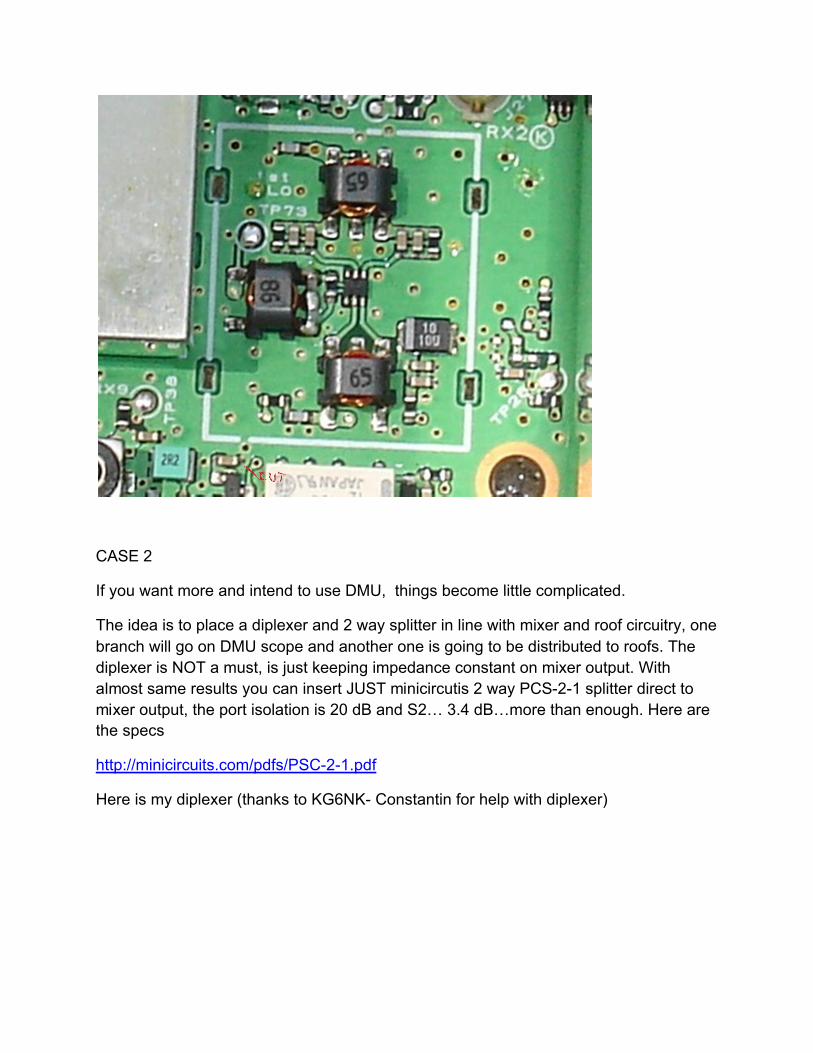
CASE 2
If you want more and intend to use DMU, things become little complicated.
The idea is to place a diplexer and 2 way splitter in line with mixer and roof circuitry, one branch will go on DMU scope and another one is going to be distributed to roofs. The diplexer is NOT a must, is just keeping impedance constant on mixer output. With almost same results you can insert JUST minicircutis 2 way PCS-2-1 splitter direct to mixer output, the port isolation is 20 dB and S2… 3.4 dB…more than enough. Here are the specs
http://minicircuits.com/pdfs/PSC-2-1.pdf
Here is my diplexer (thanks to KG6NK- Constantin for help with diplexer)

If you want to find out more abt diplexers take a look here is some theory:
http://www.qrp.pops.net/dip2.asp
so going back…
Step 1 take out the mixer shield

Step 2
The PCB is a 3 layer one…at least. So we need to cut some traces that are running in the middle…take a look in service manual:

And here is the real life…
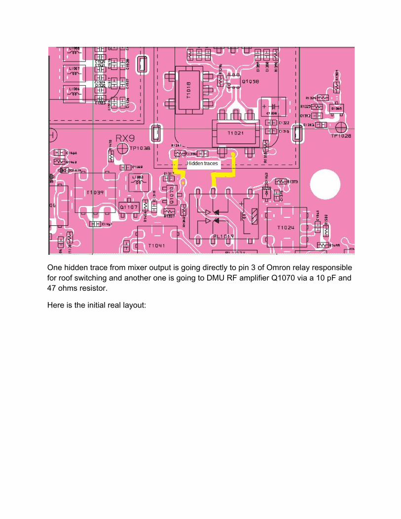
One hidden trace from mixer output is going directly to pin 3 of Omron relay responsible for roof switching and another one is going to DMU RF amplifier Q1070 via a 10 pF and 47 ohms resistor.
Here is the initial real layout:
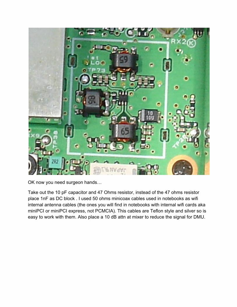
OK now you need surgeon hands…
Take out the 10 pF capacitor and 47 Ohms resistor, instead of the 47 ohms resistor place 1nF as DC block . I used 50 ohms minicoax cables used in notebooks as wifi internal antenna cables (the ones you will find in notebooks with internal wifi cards aka miniPCI or miniPCI express, not PCMCIA). This cables are Teflon style and silver so is easy to work with them. Also place a 10 dB attn at mixer to reduce the signal for DMU.
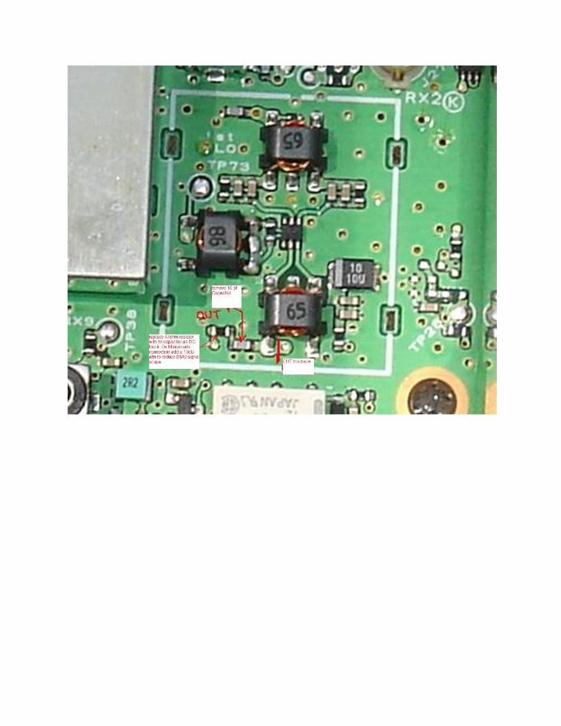

Then you need to cut the trace from mixer output (to isolate the hidden one). This is not easy and involve some good cutters and surgeon hand.
After looks like this:

Place back the shield,


Next is insertion of Inrad Roofing filter mount on motherboard with a 3dB amp that compensate the attn
I chose 3 KHz to use as Inrad config. I removed the red trimmer capacitors from both 3 KHz and 6 KHz and on 3 KHz I removed the 0 ohms jumpers resistors (Charlie zero ohm resistors), basically isolating the 3KHz and placing Inrad roof instead of stock 3 KHz.
(see section 2 for updates!!)

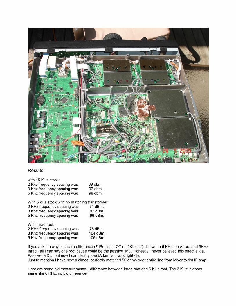
Results:
with 15 KHz stock:2 Kkz frequency spacing was 69 dbm.3 Khz frequency spacing was 97 dbm.5 Khz frequency spacing was 98 dbm.
With 6 kHz stock with no matching transformer:2 KHz frequency spacing was 71 dBm.3 Khz frequency spacing was 97 dBm.5 Khz frequency spacing was 96 dBm.
With Inrad roof:2 KHz frequency spacing was 78 dBm.3 Khz frequency spacing was 104 dBm.5 Khz frequency spacing was 106 dBm
If you ask me why is such a difference (7dBm is a LOT on 2Khz !!!!)...between 6 KHz stock roof and 5KHz Inrad...all I can say one root cause could be the passive IMD. Honestly I never believed this effect a.k.a. Passive IMD… but now I can clearly see (Adam you was right ). Just to mention I have now a almost perfectly matched 50 ohms over entire line from Mixer to 1st IF amp.
Here are some old measurements…difference between Inrad roof and 6 KHz roof. The 3 KHz is aprox same like 6 KHz, no big difference

This is Inrad roof
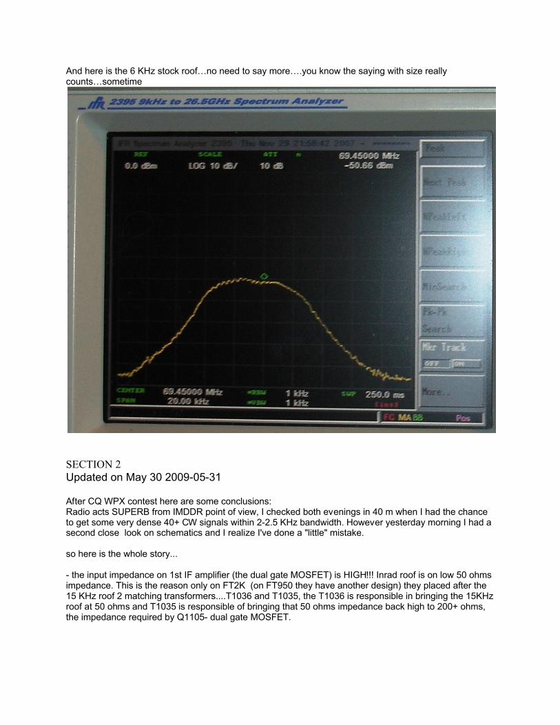
And here is the 6 KHz stock roof…no need to say more….you know the saying with size really counts…sometime
SECTION 2Updated on May 30 2009-05-31
After CQ WPX contest here are some conclusions:Radio acts SUPERB from IMDDR point of view, I checked both evenings in 40 m when I had the chance to get some very dense 40+ CW signals within 2-2.5 KHz bandwidth. However yesterday morning I had a second close look on schematics and I realize I've done a "little" mistake.
so here is the whole story...
- the input impedance on 1st IF amplifier (the dual gate MOSFET) is HIGH!!! Inrad roof is on low 50 ohms impedance. This is the reason only on FT2K (on FT950 they have another design) they placed after the 15 KHz roof 2 matching transformers....T1036 and T1035, the T1036 is responsible in bringing the 15KHz roof at 50 ohms and T1035 is responsible of bringing that 50 ohms impedance back high to 200+ ohms, the impedance required by Q1105- dual gate MOSFET.
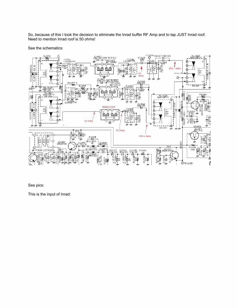
So, because of this I took the decision to eliminate the Inrad buffer RF Amp and to tap JUST Inrad roof. Need to mention Inrad roof is 50 ohms!
See the schematics:
See pics:
This is the input of Inrad:

So I took the advantage of T1040 the matching transformer that was used by 3KHz roof and insert Inrad output to input of T1040 cutting a small trace, no big deal, so now my Inrad roof stays without any buffer amp and is like this:Input Inrad connected as I specified in my mod doc on port 5 of RL 1024 and output is connected at T1040 where supposed to be C1555**** that is missing.

And this is a general assay view:

Results:
Now Inrad roof is almost same like 15 KHz roof as signal level, and this IS GOOD!!! (the difference is maybe 0.5 dB or so…)I had to retune T1040 obviously but no big deal with a siggen and a spectrum analyzer.The big problem is still 6 KHz roof, I tried to add back the red trimmer, BAD BAD BAD...took it out again and now stays on curb in garbage can, food for raccoons :-)). The 6 KHz roof without any input impedance is still 6-8 dB less than Inrad and 15 KHz, clear sign that the 6 KHz Yaesu roof is NOT 50ohms, I won't mess with it at all until I'll get the transformers from Yaesu, than I'll mount one in PCB pad and see the results and update to v3 this doc, however based on my measurements I really don't care abt 6 KHz roof as long as is kind of useless anyway.
Going back to results...The really GOOD part of the story...I break the 80dBm 2KHz IMDDR, and this is really fantastic, I gotactually 82dBm, so 3 dB more dB at 2 KHz spacing than before on v1, one explanation is the buffer Inrad amp and no necessary the matching impedance to Inrad output, or most a little bit of everything combined. This values needs to be confirmed with a parallel measurement
Speaking abt contest, with this new mode I listened yesterday night for 3-4 hours side by side Orion2 and
FT2K with a 2 way 50 ohms splitter, not bad at all, signals were very strong and no bad at all. However need to mention some more SW developments needs to be done on SW side to make us all happy.
Thanks and 73’s de
VE3GNO/YO3GJC Daniel
In memoriam of YO3GNO Nic, now sk