from iter to demo - deutsche physikalische gesellschaft · power plant stellarator physics...
TRANSCRIPT

From ITER to DEMO
Hartmut Zohm
Max-Planck-Institut für Plasmaphysik
85748 Garching
DPG Advanced Physics School‚The Physics of ITER‘
Bad Honnef, 25.09.2014

• Introduction: what is DEMO?
• DEMO technology challenges
• DEMO physics challenges
• Risk mitigation strategies

• Introduction: what is DEMO?
• DEMO technology challenges
• DEMO physics challenges
• Risk mitigation strategies

Fusion Power Plant - Challenges
Lithium compound
Cooling circuits and generator
Plasma
First wall
Structural materials
Magnets
Fusion specificauxiliaries
Breeding blanket& fuel cycle

Fusion Power Plant - Challenges
Lithium compound
Cooling circuits and generator
Plasma
First wall
Structural materials
Magnets
Fusion specificauxiliaries
Breeding blanket& fuel cycle
ITER contribution

2010 2015 2020 2025 2030 2035 2040 2045 2050 2055
DEMO-relevant technology
ITER
Pla
smap
hysi
cs
IFMIF
Tokamak physics
Firstcommercialpower plant
Stellarator physics
ITER-relevant technology
First electricityfrom fusion
DEMO
Fac
ilitie
sTe
chno
logy
A Road Map to Fusion Energy

What is DEMO?
DEMO is the step between ITER and a Fusion Power Plant (FPP)
There is no unique definition, but the goals are to demonstrate…• a workable solution for all physics and technology questions• large scale (100s of MW) net electricity production• self-sufficient fuel cycle• high reliability and availability over a reasonable time span
and allow an assessment of the economic prospects of an FPP
In the EU Roadmap, DEMO is a single step between ITER and an FPP
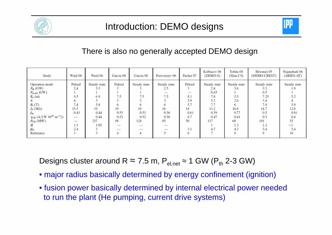
There is also no generally accepted DEMO design
Introduction: DEMO designs
Designs cluster around R ≈ 7.5 m, Pel,net ≈ 1 GW (Pth 2-3 GW)
• major radius basically determined by energy confinement (ignition)
• fusion power basically determined by internal electrical power needed to run the plant (He pumping, current drive systems)

Introduction: DEMO designs
However, there is quite a spread in optimism of assumptions
• DEMO-CREST: very moderate assumptions, building on ITER Q=10
• ARIES-AT: operation at ‘99% of all physics and technology limits’

τE and βN determine machine size
ITER (Q=10)
DEMO (ignited)
4295
342
1Aq
RBcP N
fus
β=42
95
342
1Aq
RBcP N
fus
β=
• high τE helps to achieve ignition, but does not enter in fusion power
• βN does almost not enter into Q, but strongly into fusion power
15
5
7.37.21.0
53.31.3
1
2 −=
BRH
Aqcc
Q
Nβ15
5
7.37.21.0
53.31.3
1
2 −=
BRH
Aqcc
Q
Nβ
ITER (βN=1.8)
DEMO (βN=3)
Major radius R 0 [m] Major radius R 0 [m]
Fus
ion
Pow
er [M
W]

• Introduction: what is DEMO?
• DEMO technology challenges
• DEMO physics challenges
• Risk mitigation strategies

Many solutions can be adopted from ITER – these will not be treated here
The EU programme has identified the following DEMO technology challenges, i.e. items that will qualitatively go beyond ITER
• Enabling technologies (H&CD, Diagnostics and control, T processingetc.) have to have highest availability, reliability and efficiency
• Materials have to cope with much higher n-fluences at adequatelifetime and, at the same time, low radiological burden
• T-self sufficiency has to be guaranteed
‚DEMO is no longer an experiment‘ – industry should be involved early on!
DEMO technology challenges

DEMO Technology Challenges: Structural Materials
Progress in materials development needed to fully use fusion advantages
• issues: structural stability at high temperature (Carnot efficiency) and under14 MeV n-bombardment (rise of Ductile-Brittle Transition Temperature)
• EUROFER steels up to 550o C, better: Oxide Dispersion strengthened Steel
• also reduce waste issues (fuel/burn products itself have short τ1/2 ≤ 12 yrs)
1 hr 1 day 1 year 100 years
time (log scale)
Spe
cific
act
ivity
(B
q/kg
)

Fusion Material Development – IFMIF
Construction of DEMO as first of a kind requires qualification of materials
• need dedicated facility with high n-fluence of fusion-specific spectrum
IFMIF can address this and should run several years before DEMO licensing
• important to get IFMIF going if ‚fast track‘ option should be kept
• present status: 5 years ‚EVEDA‘ (Japan/EU), then ready to build
D-Accelerator Liquid-Li Target Test cell
D-beams neutrons

Technology sets strict limits for exhaust in DEMO
• Water cooling: (safety, small Top-range (DBTT), < 5 dpa): ≤ 5-10 MW/m2
• He cooling: (higher Top-range, but development needed): ≤ 5-10 MW/m2
• in addition, Te,div ≤ 4 eV to limit erosion(consistent lifetime estimate)

DEMO Technology Challenges: Blanket
Breeding blanket must provide self-sufficient T-supply for fuel cycle
• breeding ratio > 1 needed (1 neutron per fusion reaction)
Blanket also crucial for providing high grade heat (the hotter the better)
He sub-systems
cold shield
SiC f/SiC channel inserts
EUROFER Structure (FW+Grids)
ODS Layers plated to the FW
hot shield
coolant manifold
He-2
He-1 Pb-17Li
Pb-17Li
1
2
rad.
tor.
pol.
“Dual Coolant” He-PbLi LM Blanket DesignTmax ≥ 650°C, 80-150 dpa in DEMO
EU Power Plant ConceptualDesign Study (PPCS)

• Introduction: what is DEMO?
• DEMO technology challenges
• DEMO physics challenges
• Risk mitigation strategies

ITER will address key issues for DEMO beyond present day experiments, the most prominent example being α-heating
The EU programme has identified ‘DEMO physics challenges’ (items not needed for ITER Q=10, but absolutely vital for DEMO and an FPP)
• Steady state tokamak operation at high Q
• High density operation
• Power exhaust (RDEMO/RITER = 1.2, but PDEMO/PITER = 4!)
• Disruptions (WDEMO/WITER > 5!)
• Reliable control with minimum sensors and actuators
The DEMO physics challenges

Vary βN = 2...5 and fCD = 0 (ohmic)…0.3, assume conventional technology
Objectives of acceptable frec and significant Pel,net can be fulfilled, butsufficient pulse length requires high βN > 5 (‘advanced tokamak’)!
The ‘ITER’ case: R0=7.5 m, Bt=5.2 T, A=3.1

Assuming improved technology and physics (ηCD=0.5, γCD=0.4,H=1.2), the situation is relaxed w.r.t. power…
* βN = 3.5τpulse = 8 hrsfrec = 37%Pel,net = 500 MW
…but achieving steady state is still challenging the stability limits…
⇒ pulsed and steady state options to be studied in parallel (different A!)!
⇒ high efficiency of H&CD systems becomes crucial!
The ‘ITER’ case: R0=7.5 m, Bt=5.2 T, A=3.1

Exhaust: no R-scaling of power deposition width
Under attached divertor conditions scaling yields 2 mm in the midplane(2 cm at the divertor target) in DEMO and ITER
figure of merit is Psep/R since wetted area only increaes linearly with R
02.010.020.178.073.0 geoSOLcyltorq RPqB ⋅⋅⋅⋅= −λ
Attached divertor (AUG)Ptot = 12.5 MWPtarget,max = 14.5 MW/m2
Width ~ 2 cm
# 23223; time 4.21 s

Experiments at high P/R (ASDEX Upgrade)
Feedback controlled N- seeding: qdiv < 5 MW/m2 at Pheat = 23 MW
• good core plasma performance (τE/τE,iter scaling ~ 1, βN ~ 2.8)
• present values of Psep/R up to 10 MW/m (ITER: 15 MW/m)

Exhaust problem in DEMO different from ITER
Simple P/R divertor scaling argument:
• Lower bound: ASDEX Upgrade result: Psep / R = 7 MW/m
• Upper bound: ITER assumption: Psep /R = 15 MW/m
An unprecedented ‚core‘ radiation level will be needed in DEMO!
• Prad(r) must be tailored consistent with confinement needs

Double Radiation Feedback (ASDEX Upgrade)
Now, Prad,main controlled by Ar-seeding (more radiation inside separatrix)
• still Pheat,tot = 23 MW and qdiv < 5 MW/m2, but now Prad,core = 15 MW (67%)
• close to PLH, but still τE/τE,iter scaling =1 and βN = 3!
• Introduction: what is DEMO?
• DEMO technology challenges
• DEMO physics challenges
• Risk mitigation strategies

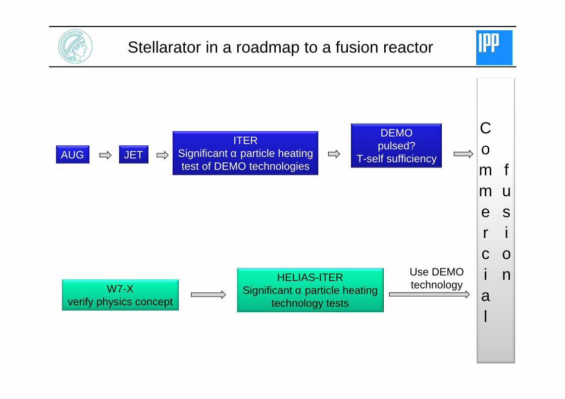
Stellarators are intrinsically steady state devices
EU programme studies stellarator line as alternative to tokamak
• no internal plasma current – no limitation to steady state plasma operation
• no disruptions since no intrinsic current
• engineering feasibility of stellarator power plant must be assessed early on
F. Schauer et al.24th SOFE (2011)
JETITER
Significant α particle heatingtest of DEMO technologies
DEMOpulsed?
T-self sufficiencyAUG
Commercial
fusion
W7-Xverify physics concept
HELIAS-ITERSignificant α particle heating
technology tests
Use DEMO technology
Stellarator in a roadmap to a fusion reactor

Optimisation of divertor geometry
The ‘snowflake divertor’ has a higher order magnetic field null
• ‘snowflake’ promises large expansionof magnetic flux and concomitant broadening of wetted area
Technological questions to be studied:
• integration into reactor (higher multipole requires closer coils)
• controllability of configuration

Optimisation of divertor geometry
‘Super-X divertor’ has very long outer divertor leg
• maximises toroidal magneticflux expansion
• promises large divertor volume and wetted area
Technological questions:
• integration into a reactor (long divertor leg → coils need to be close to plasma)
• controllability of configuration
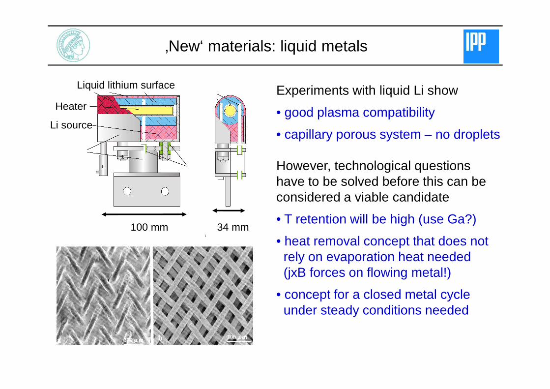
‚New‘ materials: liquid metals
Experiments with liquid Li show
• good plasma compatibility
• capillary porous system – no droplets
However, technological questions have to be solved before this can be considered a viable candidate
• T retention will be high (use Ga?)
• heat removal concept that does notrely on evaporation heat needed(jxB forces on flowing metal!)
• concept for a closed metal cycleunder steady conditions needed
Liquid lithium surface
Heater
Li source
100 mm 34 mm

Technology and physics challenges are strongly interlinked
• traditionally, physics assumptions have led to requirements fortechnology (example: divertor target has to stand 20+ MW/m2)
• not always possible to match (see above), which calls for an iteration
Technology and physics should be treated in an integrated way, applying the same level of optimism in the assumptions!
This requires engineers and physicists to sit together at one table!
• ideally, a hierarchy of design decisions is worked out
First steps to bring the two communities closer together have provento be very fruitful ☺
Concluding Remark: Physics & Technology