from bits to antenna to rf: wireless system design with matlab3gpptrend.cm.nctu.edu.tw/session...
TRANSCRIPT
1© 2014 The MathWorks, Inc.
From Bits to Antenna to RF: Wireless System Design with MATLAB
Houman Zarrinkoub, PhD.Signal Processing & [email protected]

2
Agenda
Landscape of wireless design
Antenna-to-Bit simulation
Case study: 802.11n/ac/ad Systems
Smart RF design
Case study: ADI Agile Transceiver Modeling
LTE and LTE-Advanced
Case study: MU-MIMO
Summary

3
Mobile Communications: LTE, 5G and Beyond
5G standardization
100-1000 times faster speeds
Reliable service everywhere
Greater complexity
New architectures
New frequency bands (mmWave)
More antennas (massive MIMO)
Advanced RF and DSP co-design

4
Connected Smart Devices, Internet of Things
Internet of Things
Embedded sensors
Digital health
Industrial instruments
Pervasive computing
Connected wirelessly to internet
Low power
Generate lots of data

5
Wireless System Design: MATLAB and Simulink
Who are our users?
R&D algorithm designer
Digital baseband engineer
RF system engineer
Test or validation engineer
What do they need?
End-to-end simulation
Design verification
Real-world over-the-air testing
Simulate& Analyze
ImplementPrototype & Test
Wireless SystemDesign
Multi-domainsystem
Single domainsystem
Algorithm

6
1 Antenna to Bits simulation
2Smart RF design
3LTE & LTE-Advanced
7
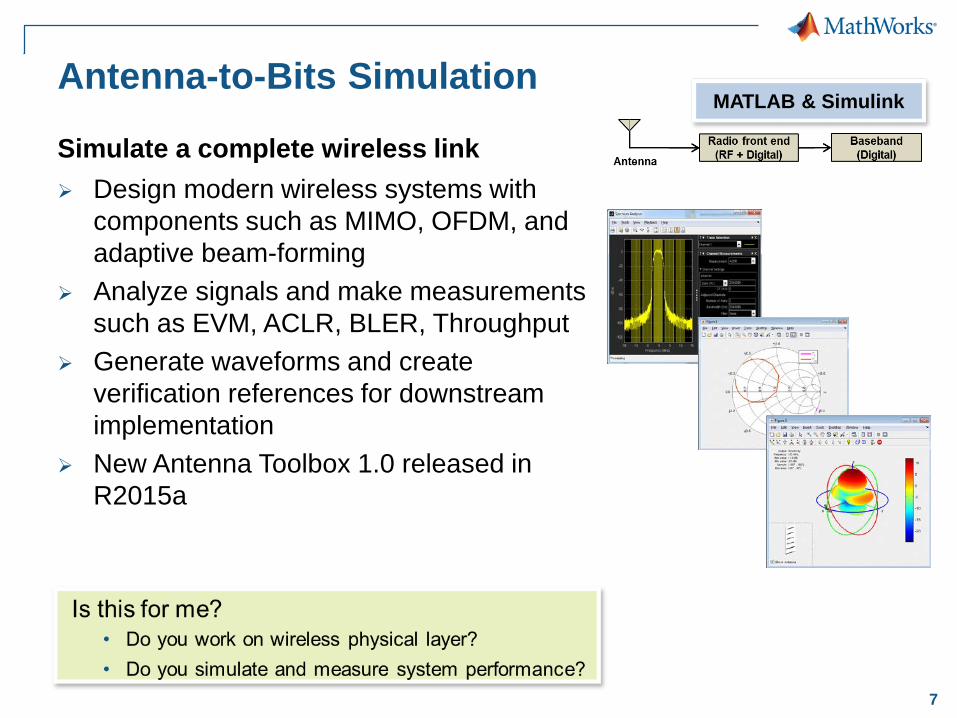
Antenna-to-Bits Simulation
Design modern wireless systems with components such as MIMO, OFDM, and adaptive beam-forming
Analyze signals and make measurements such as EVM, ACLR, BLER, Throughput
Generate waveforms and create verification references for downstream implementation
New Antenna Toolbox 1.0 released in R2015a
MATLAB & Simulink
Simulate a complete wireless link

8
Step-by-step MATLAB demo – OFDM as the air interface technology of 802.11n– Beamforming as a MIMO technique
Easy-to-follow end-to-end simulation Graphical test bench Adjustment of channel characteristics on
the fly
Demo: 802.11n/ac/ad modelinga MIMO-OFDM system

9
How does a MIMO-OFDM System work?
Input bits
ModulationChannelcoding
MIMO ....
Transmitter
Channel
Large-scale fading
(path-loss …)
Small-scale fading
(Multipath, Doppler effects)
Interference
NoiseReceiver
Channeldecoding
De-modulation
MIMOReceiver
(Equalizer)
Channel estimation
OFDMreceiver
OFDMreceiver
……
……
Output bits
10
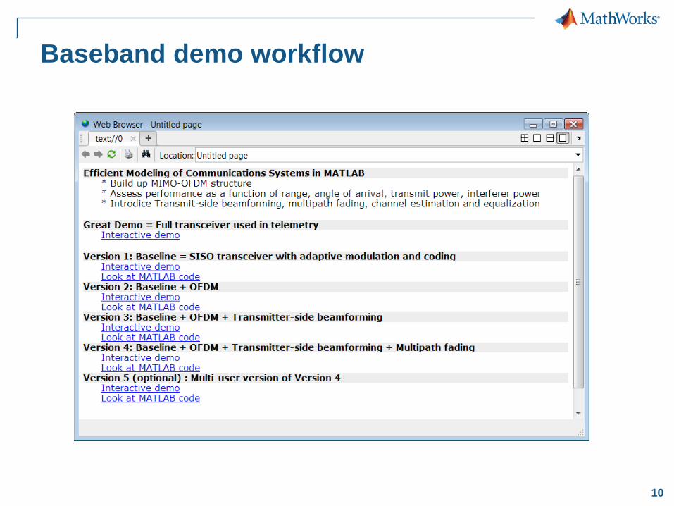
Baseband demo workflow

11
Version 1: Baseline - Modulation and Coding
Start with a SISO transceiver with modulation, coding, scrambling Channel modeling (Interferer + path loss) No multipath fading yet Isotropic (non-directional) antennas (1x1)
Signal Source (S)
InterferenceSource (I)
𝜃𝜃𝑆𝑆𝜃𝜃𝐼𝐼
𝑑𝑑𝑆𝑆𝑑𝑑𝐼𝐼

12
MATLAB tools for modeling of adaptive modulation and coding
• Use algorithms in Communications System Toolbox
• Quickly build and run fast & reliable simulations
• Simulate dynamic changes of systems (such as modulation scheme)
• Perform measurements and examine performance metrics during simulation

13
Version 2: Baseline + OFDM
Introduce OFDM transmission Transceiver with modulation, coding, scrambling & OFDM
transmitter & receiver Channel (Interferer + path loss) modeling No multipath fading yet
Signal Source (S)
InterferenceSource (I)
𝑑𝑑𝑆𝑆𝑑𝑑𝐼𝐼
14
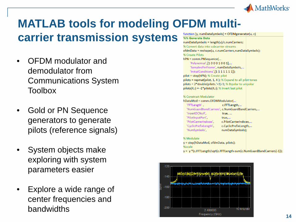
MATLAB tools for modeling OFDM multi-carrier transmission systems
• OFDM modulator and demodulator from Communications System Toolbox
• Gold or PN Sequence generators to generate pilots (reference signals)
• System objects make exploring with system parameters easier
• Explore a wide range of center frequencies and bandwidths
15
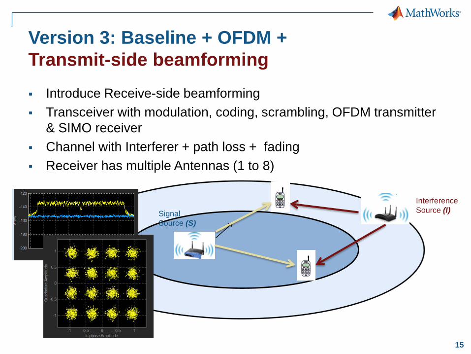
Version 3: Baseline + OFDM +Transmit-side beamforming Introduce Receive-side beamforming Transceiver with modulation, coding, scrambling, OFDM transmitter
& SIMO receiver Channel with Interferer + path loss + fading Receiver has multiple Antennas (1 to 8)
Signal Source (S)
InterferenceSource (I)
16
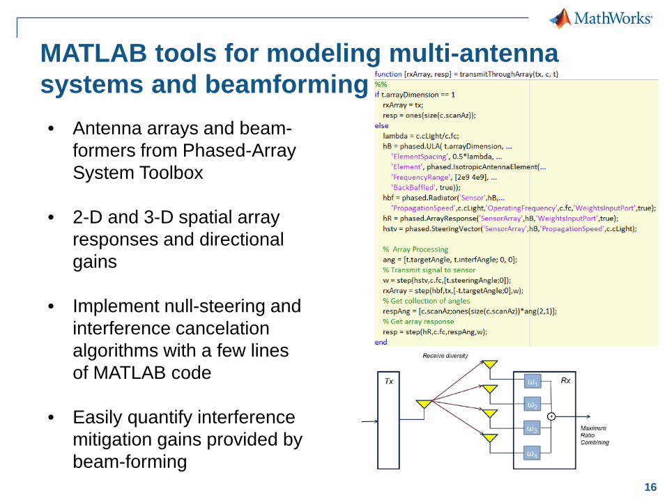
MATLAB tools for modeling multi-antenna systems and beamforming• Antenna arrays and beam-
formers from Phased-Array System Toolbox
• 2-D and 3-D spatial array responses and directional gains
• Implement null-steering and interference cancelation algorithms with a few lines of MATLAB code
• Easily quantify interference mitigation gains provided by beam-forming

17
Version 4: Baseline + OFDM +Transmit-side beamforming + Multipath fading Introduce Transmit-side beamforming with Multipath fading Transceiver with modulation, coding, scrambling, MIMO-OFDM
transmitter & receiver Channel with Interferer + path loss + fading Transmitter has multiple Antennas (1 to 8)
Signal Source (S)
InterferenceSource (I)
18
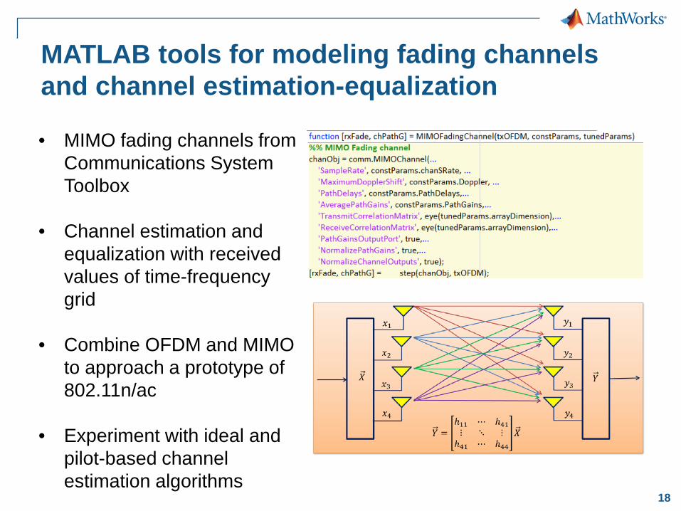
MATLAB tools for modeling fading channels and channel estimation-equalization
• MIMO fading channels from Communications System Toolbox
• Channel estimation and equalization with received values of time-frequency grid
• Combine OFDM and MIMO to approach a prototype of 802.11n/ac
• Experiment with ideal and pilot-based channel estimation algorithms
19
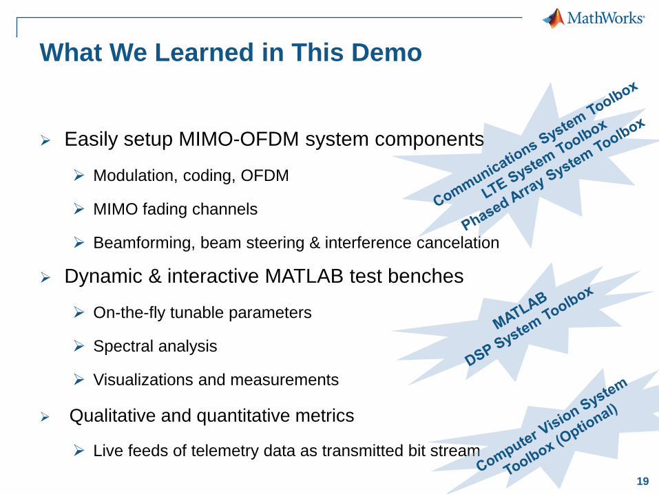
What We Learned in This Demo
Easily setup MIMO-OFDM system components
Modulation, coding, OFDM
MIMO fading channels
Beamforming, beam steering & interference cancelation
Dynamic & interactive MATLAB test benches
On-the-fly tunable parameters
Spectral analysis
Visualizations and measurements
Qualitative and quantitative metrics
Live feeds of telemetry data as transmitted bit stream

20
Antenna Toolbox Easy design
– Library of 22 parameterized antenna elements– Functionality for the design of linear and
rectangular antenna arrays – No need for full CAD design
Rapid simulation setup– Method of Moments field solver for port, field,
and surface analysis – No need to be an EM expert
Seamless integration– Model the antenna together with signal
processing algorithms– Rapid iteration of different antenna scenarios
for radar and communication systems design
21
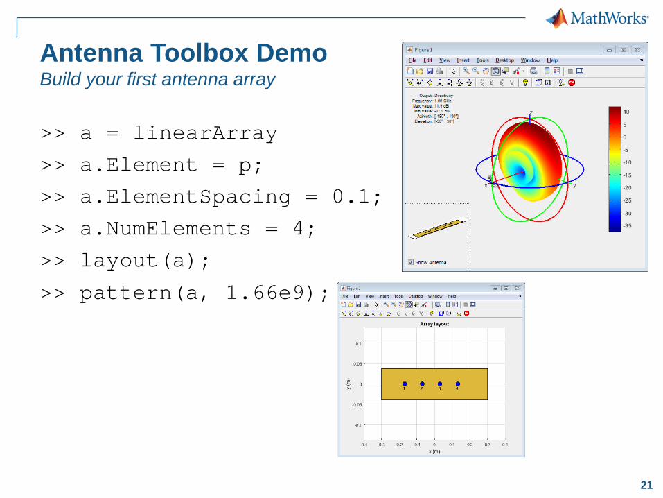
Antenna Toolbox DemoBuild your first antenna array
>> a = linearArray
>> a.Element = p;
>> a.ElementSpacing = 0.1;
>> a.NumElements = 4;
>> layout(a);
>> pattern(a, 1.66e9);

22
Integration Demo: Phased Array System Toolboxatx_array_modeling_with_embedded_element_pattern
...
% Import antenna element in Phased Array
myURA1 = phased.URA;myURA1.Element = mydipole;...
% Import the embedded element pattern
EmbAnt = Phased.CustomAntennaElement(...
'FrequencyVector',freqVector,... 'AzimuthAngles',az,... 'ElevationAngles',el,... 'RadiationPattern',embpattern);
myURA2 = phased.URA;
myURA2.Element = EmbAnt;
...
Antenna element
Pattern of the embedded element computed with Antenna Toolbox
Phased Array
23
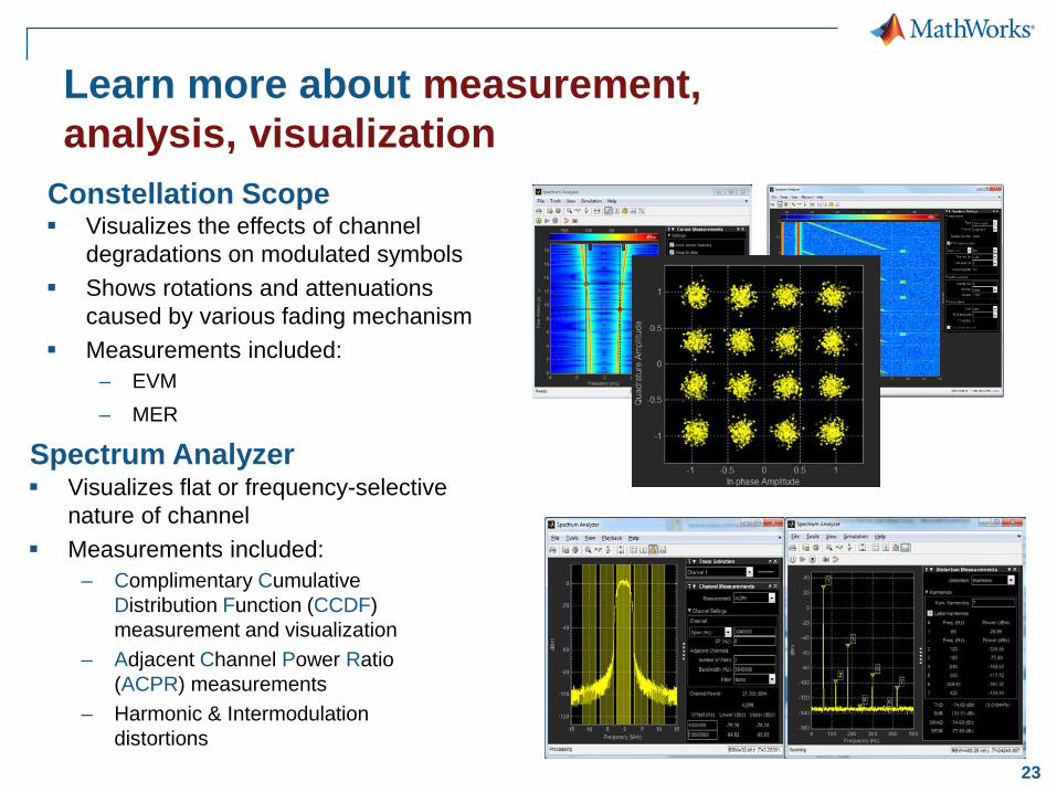
Learn more about measurement, analysis, visualization
Constellation Scope Visualizes the effects of channel
degradations on modulated symbols Shows rotations and attenuations
caused by various fading mechanism Measurements included:
– EVM – MER
Spectrum Analyzer Visualizes flat or frequency-selective
nature of channel Measurements included:
– Complimentary Cumulative Distribution Function (CCDF) measurement and visualization
– Adjacent Channel Power Ratio (ACPR) measurements
– Harmonic & Intermodulation distortions
24
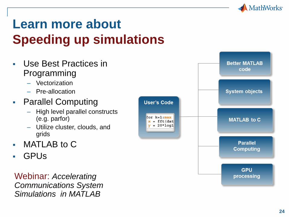
Learn more about Speeding up simulations Use Best Practices in
Programming – Vectorization – Pre-allocation
Parallel Computing– High level parallel constructs
(e.g. parfor)– Utilize cluster, clouds, and
grids
MATLAB to C GPUs
Webinar: Accelerating Communications System Simulations in MATLAB
25
Summary
We have modern algorithms (OFDM and MIMO) & analysis tools and even modern standard-based products (LTE) for modern systems
We have incorporated features and tools like C code generation, parallel computing etc. into our tool that “substantially” accelerate simulation
We now have very high end communications measurements and analysis tools like Spectrum Analyzers, etc. They work directly in MATLAB and come at the low toolbox price
26
1 Antenna to Bits simulation
2Smart RF design
3LTE & LTE-Advanced

27
Smart RF Design
Model and simulate RF transceiver together with baseband algorithms
Develop calibration and control algorithms such as DPD or AGC to mitigate impairments and interferers
Add measured RF component characteristics
Use circuit envelope techniques to accelerate simulation of RF transceivers
Fast behavioral RF modeling & simulation MATLAB & Simulink
Analog Devices AD9361RF Agile Transceiver™

28
AGC RSSI
Example: Simulation of Analog Devices® RF Transceivers with MATLAB and SimRF

29
CW test signal
LTE-like or custom test signal
Multi-rate finite-precision programmable decimation filters
Analog continuous-time programmable filters
Tunable RF receiver
RF Receiver
Third order Delta-Sigma ADC
RSSI
AGCManual and slow attack mode
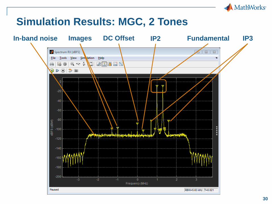
30
Simulation Results: MGC, 2 TonesFundamentalDC Offset IP2 IP3In-band noise Images

31
Which Tools? MATLAB, Simulink and …

32
Learn More About: RF Modeling
SimRF: fast simulation of RF front-ends Design the architecture and specs of the RF front-end
Integrate RF with adaptive algorithms such as DPD, AGC
Test and debug the implementation before going in the lab
Provide a model to your colleagues and customers
Webinar: Design and Verify RF Transceivers for Wireless Communication Systems

33
Trade Off Simulation Speed and Modeling FidelityHow do your signals look like?
Modeling fidelity
Sim
ulat
ion
spee
d
True Pass-Band
Circuit Envelope
Equivalent Baseband
Carrier
Signal bandwidth
freq
Spe
ctru
m
Carrier 1 freq
Spe
ctru
m
Carrier 2DC
freq
Spe
ctru
m

34
Summary
Executable specifications of real-life communication systems across multiple disciplines Develop smarter algorithms faster Improve the communication between different teams Understand, debug, test your system before going in the lab Provide (IP protected) models to the end users

35
1 Antenna to Bits simulation
2Smart RF design
3LTE & LTE-Advanced

36
LTE & LTE-Advanced
Specify your LTE and LTE-A PHY systems covering all transmission modes, channels, and signals
Combine your LTE baseband models with RF modeling for a combined digital-RF design
New features in R2015a LTE Rel. 11 support UMTS/HSPA+ Waveform Generation Coordinated Multipoint (CoMP)
Qualifying question• Are you working on LTE Physical layer?
Design, simulate, and test LTE and LTE-Advanced systems
MATLAB & Simulink

37
What’s the LTE System Toolbox?
Release 8,9, 10 &11 (LTE-A) Scope
– TDD/FDD, – Uplink/Downlink– Transmitter/Receiver
~200 functions for physical layer (PHY) modeling
Link-level simulation Conformance Tests
38
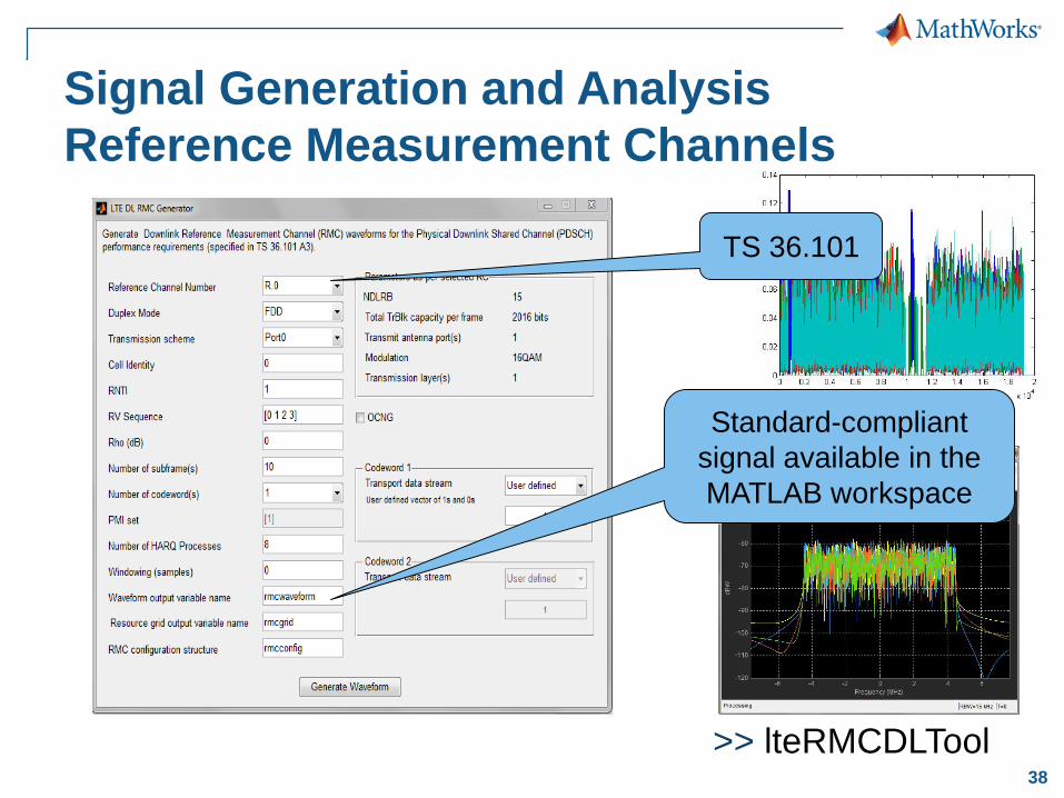
Signal Generation and Analysis Reference Measurement Channels
>> lteRMCDLTool
Standard-compliant signal available in the MATLAB workspace
TS 36.101

39
Typical Use Cases
Golden reference to verify in-house PHY models
Complete end-to-end link-level simulation
Signal generation and analysis
Signal information recovery
RF Signal GeneratorTransmitter
Test Waveform Generation
40
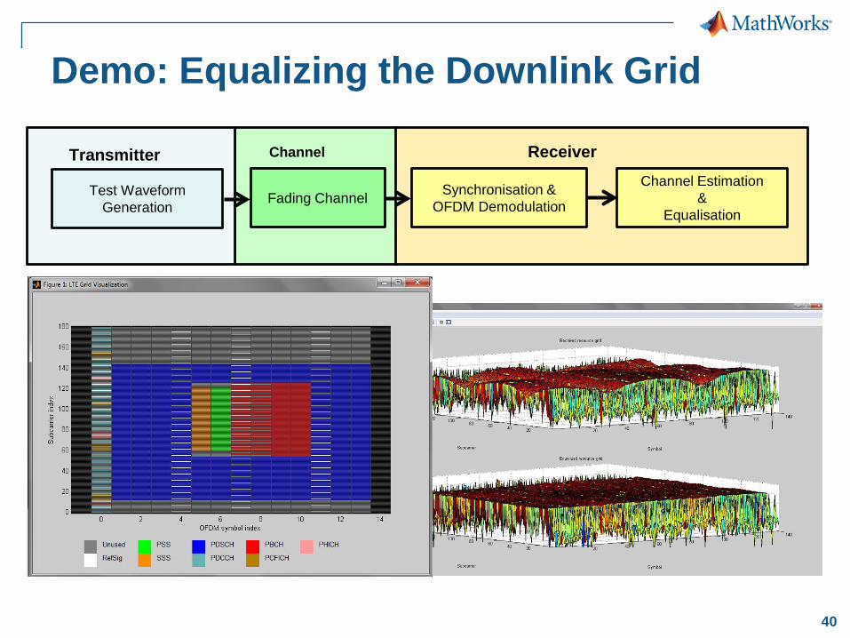
Demo: Equalizing the Downlink Grid
ReceiverTransmitter Channel
Test Waveform Generation
Synchronisation & OFDM Demodulation
Channel Estimation&
EqualisationFading Channel

41
Summary
Comprehensive– Comprehensive set of PHY models– Numerous preset, extensible examples
Open environment– MATLAB-based– Link to test and measurement instruments
Standard-compliance– Ability to generate and transmit signals using hardware signal generators– Trusted by numerous customers