frn 1.xx - 4 - rockwell automation...frn 1.xx - 4.xx quick start 400p fcover.fm page 1 wednesday,...
TRANSCRIPT
www.abpowerflex.com
fcover.fm Page 1 Wednesday, November 23, 2016 4:24 PM
400P
AdjustableFrequency ACDrive forGeneral IndustrialApplicationsFRN 1.xx - 4.xx
400P
Quick Start
fcover.fm Page 2 Wednesday, November 23, 2016 4:24 PM
Important User InformationSolid state equipment has operational characteristics differing from those of electromechanical equipment. Safety Guidelines for the Application, Installation and Maintenance of Solid State Controls (Publication SGI-1.1 available from your local Rockwell Automation sales office or online at http://www.rockwellautomation.com/literature) describes some important differences between solid state equipment and hard-wired electromechanical devices. Because of this difference, and also because of the wide variety of uses for solid state equipment, all persons responsible for applying this equipment must satisfy themselves that each intended application of this equipment is acceptable.
In no event will Rockwell Automation, Inc. be responsible or liable for indirect or consequential damages resulting from the use or application of this equipment.
The examples and diagrams in this manual are included solely for illustrative purposes. Because of the many variables and requirements associated with any particular installation, Rockwell Automation, Inc. cannot assume responsibility or liability for actual use based on the examples and diagrams.
No patent liability is assumed by Rockwell Automation, Inc. with respect to use of information, circuits, equipment, or software described in this manual.
Reproduction of the contents of this manual, in whole or in part, without written permission of Rockwell Automation, Inc. is prohibited.
Throughout this manual, when necessary we use notes to make you aware of safety considerations.
Important: Identifies information that is critical for successful application and understanding of the product.
Allen-Bradley, Rockwell Automation, and PowerFlex are registered trademarks of Rockwell Automation, Inc.
DriveExplorer, DriveExecutive, and SCANport are trademarks of Rockwell Automation, Inc.
Trademarks not belonging to Rockwell Automation are property of their respective companies.
WARNING: Identifies information about practices or circumstances that can cause an explosion in a hazardous environment, which may lead to personal injury or death, property damage, or economic loss.
ATTENTION: Identifies information about practices or circumstances that can lead to personal injury or death, property damage, or economic loss. Attentions help you:• identify a hazard• avoid the hazard• recognize the consequences
Shock Hazard labels may be located on or inside the equipment (e.g., drive or motor) to alert people that dangerous voltage may be present.
Burn Hazard labels may be located on or inside the equipment (e.g., drive or motor) to alert people that surfaces may be at dangerous temperatures.

22P-QS001C-EN-P.fm Page 1 Thursday, March 30, 2017 5:55 PM
Quick Start
PowerFlex 400P Adjustable Frequency AC Drive
FRN 4.xx
This Quick Start guide summarizes the basic steps needed to install, start-up and program the PowerFlex 400P Adjustable Frequency AC Drive. The information provided Does Not replace the User Manual and is intended for qualified drive service personnel only.For detailed PowerFlex 400P information including EMC instructions, application considerations and related precautions refer to the PowerFlex 400P User Manual, publication 22P-UM001.
General Precautions
!ATTENTION: To avoid an electric shock hazard, verify that the voltage on the bus capacitors has discharged before performing any work on the drive. Measure the DC bus voltage at the –DC and +DC terminals or at the –DC and P2 terminals on the Power Terminal Block (refer to Chapter 1 of the User Manual for Power Terminal descriptions). The voltage must be zero.
A darkened LCD display and LEDs is not an indication that capacitors have discharged to safe voltage levels.
!ATTENTION: Only qualified personnel familiar with adjustable frequency AC drives and associated machinery should plan or implement the installation, start-up and subsequent maintenance of the system. Failure to comply may result in personal injury and/or equipment damage.
!ATTENTION: This drive contains ESD (Electrostatic Discharge) sensitive parts and assemblies. Static control precautions are required when installing, testing, servicing or repairing this assembly. Component damage may result if ESD control procedures are not followed. If you are not familiar with static control procedures, reference A-B publication 8000-4.5.2, “Guarding Against Electrostatic Damage” or any other applicable ESD protection handbook.
!ATTENTION: An incorrectly applied or installed drive can result in component damage or a reduction in product life. Wiring or application errors, such as, undersizing the motor, incorrect or inadequate AC supply, or excessive ambient temperatures may result in malfunction of the system.
English-2 PowerFlex 400P Adjustable Frequency AC Drive Quick Start
22P-QS001C-EN-P.fm Page 2 Thursday, March 30, 2017 5:55 PM
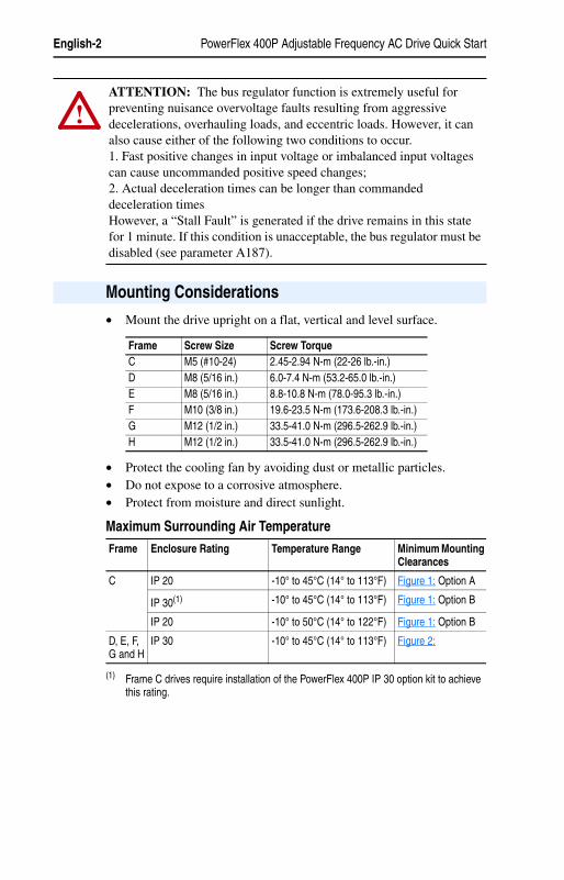
• Mount the drive upright on a flat, vertical and level surface.
• Protect the cooling fan by avoiding dust or metallic particles.• Do not expose to a corrosive atmosphere.• Protect from moisture and direct sunlight.
Maximum Surrounding Air Temperature
!ATTENTION: The bus regulator function is extremely useful for preventing nuisance overvoltage faults resulting from aggressive decelerations, overhauling loads, and eccentric loads. However, it can also cause either of the following two conditions to occur.1. Fast positive changes in input voltage or imbalanced input voltages can cause uncommanded positive speed changes;2. Actual deceleration times can be longer than commanded deceleration timesHowever, a “Stall Fault” is generated if the drive remains in this state for 1 minute. If this condition is unacceptable, the bus regulator must be disabled (see parameter A187).
Mounting Considerations
Frame Screw Size Screw TorqueC M5 (#10-24) 2.45-2.94 N-m (22-26 lb.-in.)D M8 (5/16 in.) 6.0-7.4 N-m (53.2-65.0 lb.-in.)E M8 (5/16 in.) 8.8-10.8 N-m (78.0-95.3 lb.-in.)F M10 (3/8 in.) 19.6-23.5 N-m (173.6-208.3 lb.-in.)G M12 (1/2 in.) 33.5-41.0 N-m (296.5-262.9 lb.-in.)H M12 (1/2 in.) 33.5-41.0 N-m (296.5-262.9 lb.-in.)
Frame Enclosure Rating Temperature Range Minimum Mounting Clearances
C IP 20 -10° to 45°C (14° to 113°F) Figure 1: Option A
IP 30(1)
(1) Frame C drives require installation of the PowerFlex 400P IP 30 option kit to achieve this rating.
-10° to 45°C (14° to 113°F) Figure 1: Option B
IP 20 -10° to 50°C (14° to 122°F) Figure 1: Option B
D, E, F, G and H
IP 30 -10° to 45°C (14° to 113°F) Figure 2:

PowerFlex 400P Adjustable Frequency AC Drive Quick Start English-3
22P-QS001C-EN-P.fm Page 3 Thursday, March 30, 2017 5:55 PM
Minimum Mounting Clearances
Figure 1: Frame C Mounting Clearances
Figure 2: Frames D, E, F, G, and H Mounting Clearances
120 mm(4.7 in.)
120 mm(4.7 in.)
25 mm(1.0 in.)
120 mm(4.7 in.)
120 mm(4.7 in.)
120 mm(4.7 in.)
120 mm(4.7 in.)
120 mm(4.7 in.)
120 mm(4.7 in.)
Mounting Option BMounting Option ANo clearance required between drives.
Closest object that may restrict air flow
through the drive heat sink and chassis.
150 mm(6.0 in.)
150 mm(6.0 in.)
50 mm(2.0 in.)
250 mm(9.8 in.)
150 mm(6.0 in.)
300 mm(11.8 in.)
300 mm(11.8 in.)
300 mm(11.8 in.)
300 mm(11.8 in.)
50 mm(2.0 in.)
50 mm(2.0 in.)
50 mm(2.0 in.)
Frame D and E Frame F Frame G and H
English-4 PowerFlex 400P Adjustable Frequency AC Drive Quick Start
22P-QS001C-EN-P.fm Page 4 Thursday, March 30, 2017 5:55 PM
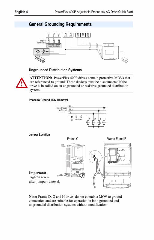
Ungrounded Distribution Systems
Phase to Ground MOV Removal
Jumper Location
Note: Frame D, G and H drives do not contain a MOV to ground connection and are suitable for operation in both grounded and ungrounded distribution systems without modification.
General Grounding Requirements
PEL1R
L2S
L3T
T1U
T2V
T3W
PE
RequiredInput Fusing
Required BranchCircuit Disconnect
!ATTENTION: PowerFlex 400P drives contain protective MOVs that are referenced to ground. These devices must be disconnected if the drive is installed on an ungrounded or resistive grounded distribution system.
R/L1S/L2T/L3
1 2 3 4
Three-PhaseAC Input
Jumper
Frame C Frame E and F
Important:Tighten screw after jumper removal.
PowerFlex 400P Adjustable Frequency AC Drive Quick Start English-5
22P-QS001C-EN-P.fm Page 5 Thursday, March 30, 2017 5:55 PM
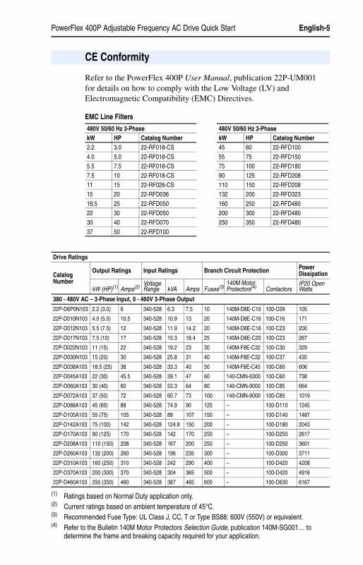
Refer to the PowerFlex 400P User Manual, publication 22P-UM001for details on how to comply with the Low Voltage (LV) and Electromagnetic Compatibility (EMC) Directives.
EMC Line Filters
CE Conformity
480V 50/60 Hz 3-Phase 480V 50/60 Hz 3-PhasekW HP Catalog Number kW HP Catalog Number2.2 3.0 22-RF018-CS 45 60 22-RFD1004.0 5.0 22-RF018-CS 55 75 22-RFD1505.5 7.5 22-RF018-CS 75 100 22-RFD1807.5 10 22-RF018-CS 90 125 22-RFD20811 15 22-RF026-CS 110 150 22-RFD20815 20 22-RFD036 132 200 22-RFD32318.5 25 22-RFD050 160 250 22-RFD48022 30 22-RFD050 200 300 22-RFD48030 40 22-RFD070 250 350 22-RFD48037 50 22-RFD100
Drive Ratings
Catalog Number
Output Ratings Input Ratings Branch Circuit Protection Power Dissipation
kW (HP)(1) Amps(2) Voltage Range kVA Amps Fuses(3)
140M Motor Protectors(4) Contactors
IP20 Open Watts
380 - 480V AC – 3-Phase Input, 0 - 460V 3-Phase Output
22P-D6P0N103 2.2 (3.0) 6 340-528 6.3 7.5 10 140M-D8E-C10 100-C09 105
22P-D010N103 4.0 (5.0) 10.5 340-528 10.9 13 20 140M-D8E-C16 100-C16 171
22P-D012N103 5.5 (7.5) 12 340-528 11.9 14.2 20 140M-D8E-C16 100-C23 200
22P-D017N103 7.5 (10) 17 340-528 15.3 18.4 25 140M-D8E-C20 100-C23 267
22P-D022N103 11 (15) 22 340-528 19.2 23 30 140M-F8E-C32 100-C30 329
22P-D030N103 15 (20) 30 340-528 25.8 31 40 140M-F8E-C32 100-C37 435
22P-D038A103 18.5 (25) 38 340-528 33.3 40 50 140M-F8E-C45 100-C60 606
22P-D045A103 22 (30) 45.5 340-528 39.1 47 60 140-CMN-6300 100-C60 738
22P-D060A103 30 (40) 60 340-528 53.3 64 80 140-CMN-9000 100-C85 664
22P-D072A103 37 (50) 72 340-528 60.7 73 100 140-CMN-9000 100-C85 1019
22P-D088A103 45 (60) 88 340-528 74.9 90 125 – 100-D110 1245
22P-D105A103 55 (75) 105 340-528 89 107 150 – 100-D140 1487
22P-D142A103 75 (100) 142 340-528 124.8 150 200 – 100-D180 2043
22P-D170A103 90 (125) 170 340-528 142 170 250 – 100-D250 2617
22P-D208A103 110 (150) 208 340-528 167 200 250 – 100-D250 3601
22P-D260A103 132 (200) 260 340-528 196 235 300 – 100-D300 3711
22P-D310A103 160 (250) 310 340-528 242 290 400 – 100-D420 4208
22P-D370A103 200 (300) 370 340-528 304 365 500 – 100-D420 4916
22P-D460A103 250 (350) 460 340-528 387 465 600 – 100-D630 6167
(1) Ratings based on Normal Duty application only.(2) Current ratings based on ambient temperature of 45°C.(3) Recommended Fuse Type: UL Class J, CC, T or Type BS88; 600V (550V) or equivalent.(4) Refer to the Bulletin 140M Motor Protectors Selection Guide, publication 140M-SG001… to
determine the frame and breaking capacity required for your application.
English-6 PowerFlex 400P Adjustable Frequency AC Drive Quick Start
22P-QS001C-EN-P.fm Page 6 Thursday, March 30, 2017 5:55 PM
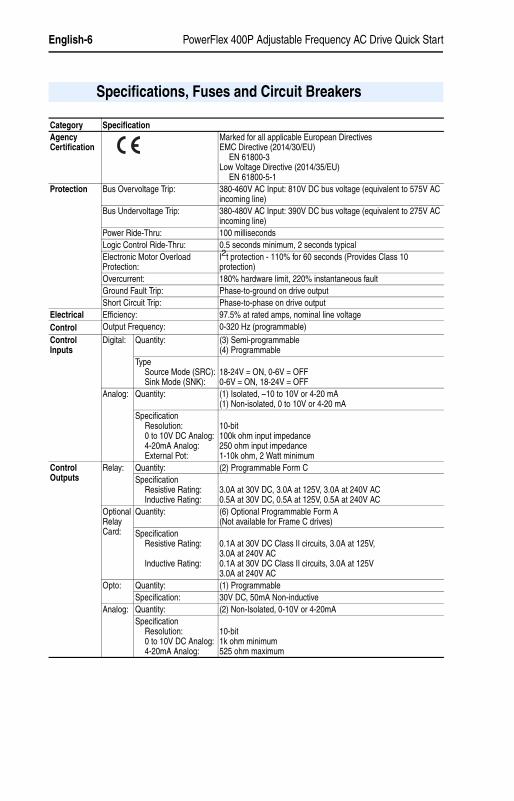
Specifications, Fuses and Circuit Breakers
Category SpecificationAgency Certification
Marked for all applicable European DirectivesEMC Directive (2014/30/EU)
EN 61800-3Low Voltage Directive (2014/35/EU)
EN 61800-5-1Protection Bus Overvoltage Trip: 380-460V AC Input: 810V DC bus voltage (equivalent to 575V AC
incoming line)Bus Undervoltage Trip: 380-480V AC Input: 390V DC bus voltage (equivalent to 275V AC
incoming line)Power Ride-Thru: 100 millisecondsLogic Control Ride-Thru: 0.5 seconds minimum, 2 seconds typicalElectronic Motor Overload Protection:
I2t protection - 110% for 60 seconds (Provides Class 10 protection)
Overcurrent: 180% hardware limit, 220% instantaneous faultGround Fault Trip: Phase-to-ground on drive outputShort Circuit Trip: Phase-to-phase on drive output
Electrical Efficiency: 97.5% at rated amps, nominal line voltageControl Output Frequency: 0-320 Hz (programmable)Control Inputs
Digital: Quantity: (3) Semi-programmable(4) Programmable
TypeSource Mode (SRC):Sink Mode (SNK):
18-24V = ON, 0-6V = OFF0-6V = ON, 18-24V = OFF
Analog: Quantity: (1) Isolated, –10 to 10V or 4-20 mA(1) Non-isolated, 0 to 10V or 4-20 mA
SpecificationResolution:0 to 10V DC Analog:4-20mA Analog:External Pot:
10-bit100k ohm input impedance250 ohm input impedance1-10k ohm, 2 Watt minimum
Control Outputs
Relay: Quantity: (2) Programmable Form CSpecification
Resistive Rating:Inductive Rating:
3.0A at 30V DC, 3.0A at 125V, 3.0A at 240V AC0.5A at 30V DC, 0.5A at 125V, 0.5A at 240V AC
Optional Relay Card:
Quantity: (6) Optional Programmable Form A(Not available for Frame C drives)
SpecificationResistive Rating:
Inductive Rating:
0.1A at 30V DC Class II circuits, 3.0A at 125V,3.0A at 240V AC0.1A at 30V DC Class II circuits, 3.0A at 125V3.0A at 240V AC
Opto: Quantity: (1) ProgrammableSpecification: 30V DC, 50mA Non-inductive
Analog: Quantity: (2) Non-Isolated, 0-10V or 4-20mASpecification
Resolution:0 to 10V DC Analog:4-20mA Analog:
10-bit1k ohm minimum525 ohm maximum

PowerFlex 400P Adjustable Frequency AC Drive Quick Start English-7
22P-QS001C-EN-P.fm Page 7 Thursday, March 30, 2017 5:55 PM
Figure 3: Power Terminal Blocks
Power Wiring
R/L1 S/L2 T/L3 P1 P2 DC– U/T1 V/T2 W/T3
Frame E:480V55-75kW(75-100HP)
Frame D
R/L1 S/L2 T/L3 P1 P2 DC– U/T1 V/T2 W/T3
Frame CR/L1 S/L2 T/L3 U/T1 V/T2 W/T3 P2 P1
BR–BR+DC+DC–
Frame E:480V37-45kW(50-60HP)R/L1S/L2T/L3 P1 P2 DC– U/T1V/T2W/T3
R/L1 S/L2 T/L3 P1 P2 DC– U/T1 V/T2 W/T3
Frame F
Frame G
Frame H
R/L1
R/L1
S/L2
S/L2
T/L3
T/L3
P1 P2 DC–
DC–DC+
U/T1
U/T1
V/T2
V/T2
W/T3
W/T3
See note on thefollowing page.

English-8 PowerFlex 400P Adjustable Frequency AC Drive Quick Start
22P-QS001C-EN-P.fm Page 8 Thursday, March 30, 2017 5:55 PM
Important: For Frame E, 480V 55-75 kW (75-100 HP) drives, take care to place the wire beneath the jumper and not above it when connecting to terminals P1 and P2.
Terminal (1) DescriptionR/L1, S/L2, T/L3 3-Phase InputU/T1 To Motor U/T1
=Switch any two motor leads to change forward direction.
V/T2 To Motor V/T2W/T3 To Motor W/T3
P2, P1
DC Bus Inductor Connection
Drives are shipped with a jumper between Terminals P2 and P1. Remove this jumper only when a DC Bus Inductor will be connected. Drive will not power up without a jumper or inductor connected.
DC–, DC+ DC Bus Connection (Frame C and H Drives)P2, DC– DC Bus Connection (Frame D, E, F and G Drives)BR+, BR– Not Used
Safety Ground - PE
(1) Important: Terminal screws may become loose during shipment. Ensure that all terminal screws are tightened to the recommended torque before applying power to the drive.
P1 P2 DC- P1 P2 DC-
Wire
Jumper WireJumper
Correct Incorrect
Bottom view of terminal block and wire

PowerFlex 400P Adjustable Frequency AC Drive Quick Start English-9
22P-QS001C-EN-P.fm Page 9 Thursday, March 30, 2017 5:55 PM
Power Terminal Block Specifications
Important: Frame C, D, F, G and H drives utilize a finger guard over the power wiring terminals. Replace the finger guard when wiring is complete.
Refer to the PowerFlex 400P User Manual for maximum power cable length recommendations.
Input Power Conditions
Frame Maximum Wire Size(1)
(1) Maximum/minimum sizes that the terminal block will accept - these are not recommendations. If national or local codes require sizes outside this range, lugs may be used. Some ratings will require a pair of wires.
Minimum Wire Size (1) Recommended Torque
C 8.4 mm2 (8 AWG) 1.3 mm2 (16 AWG) 2.9 N-m (26 lb.-in.)
D 33.6 mm2 (2 AWG) 8.4 mm2 (8 AWG) 5.1 N-m (45 lb.-in.)
E 480V37-45 kW(50-60 HP)
33.6 mm2 (2 AWG) 3.5 mm2 (12 AWG) 5.6 N-m (49.5 lb.-in.)
E 480V55-75 kW(75-100 HP)
107.2 mm2 (4/0 AWG) 53.5 mm2 (1/0 AWG) 19.5 N-m (173 lb.-in.)
F 152.5 mm2 (300 MCM) 85.0 mm2 (3/0 AWG) 19.5 N-m (173 lb.-in.)
G 152.5 mm2 (300 MCM) 85.0 mm2 (3/0 AWG) 29.4 N-m (260 lb.-in.)
H 253.0 mm2 (500 MCM) 127.0 mm2 (250 MCM) 40.0 N-m (354 lb.-in.)
Input Power Condition Corrective Action
Low Line Impedance (less than 1% line reactance)
• Install Line Reactor(1)
• or Isolation Transformer
(1) Refer to the PowerFlex 400P User Manual for information on ordering accessories.
Line has power factor correction capacitors • Install Line Reactor(1)
• or Isolation TransformerLine has frequent power interruptions
Line has intermittent noise spikes in excess of 6000V (lightning)
Phase to ground voltage exceeds 125% of normal line to line voltage
• Remove MOV jumper to ground (Frame C, E and F drives only)
• or Install Isolation Transformer with grounded secondary if necessary
Ungrounded distribution system
English-10 PowerFlex 400P Adjustable Frequency AC Drive Quick Start
22P-QS001C-EN-P.fm Page 10 Thursday, March 30, 2017 5:55 PM
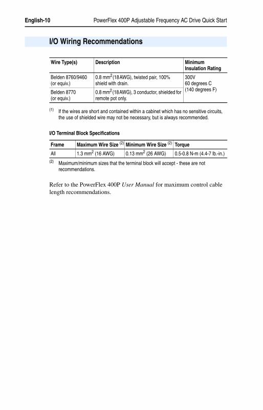
I/O Terminal Block Specifications
(2) Maximum/minimum sizes that the terminal block will accept - these are not recommendations.
Refer to the PowerFlex 400P User Manual for maximum control cable length recommendations.
I/O Wiring Recommendations
Wire Type(s) Description Minimum Insulation Rating
Belden 8760/9460(or equiv.)
0.8 mm2(18AWG), twisted pair, 100% shield with drain. (1)
(1) If the wires are short and contained within a cabinet which has no sensitive circuits, the use of shielded wire may not be necessary, but is always recommended.
300V60 degrees C(140 degrees F)Belden 8770
(or equiv.)0.8 mm2(18AWG), 3 conductor, shielded for remote pot only.
Frame Maximum Wire Size (2) Minimum Wire Size (2) Torque
All 1.3 mm2 (16 AWG) 0.13 mm2 (26 AWG) 0.5-0.8 N-m (4.4-7 lb.-in.)
PowerFlex 400P Adjustable Frequency AC Drive Quick Start English-11
22P-QS001C-EN-P.fm Page 11 Thursday, March 30, 2017 5:55 PM
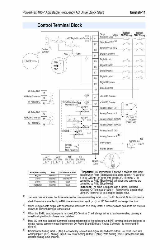
(1)Important: I/O Terminal 01 is always a coast to stop input except when P036 [Start Source] is set to option 1 “3-Wire” or 6 “2-W Lvl/Enbl”. In three wire control, I/O Terminal 01 is controlled by P037 [Stop Mode]. All other stop sources are controlled by P037 [Stop Mode]. Important: The drive is shipped with a jumper installed between I/O Terminals 01 and 11. Remove this jumper when using I/O Terminal 01 as a stop or enable input.
(2) Two wire control shown. For three wire control use a momentary input on I/O Terminal 02 to command a start. If reverse is enabled by A166, use a maintained input for I/O Terminal 03 to change direction.
(3) When using an opto output with an inductive load such as a relay, install a recovery diode parallel to the relay as shown, to prevent damage to the output.
(4) When the ENBL enable jumper is removed, I/O Terminal 01 will always act as a hardware enable, causing a coast to stop without software interpretation.
(5) Most I/O terminals labeled “Common” are not referenced to the safety ground (PE) terminal and are designed to greatly reduce common mode interference. On Frame D and E drives, Analog Common 1 is referenced to ground.
(6) Common for Analog Input 2 (AI2). Electronically isolated from digital I/O and opto output. Not to be used with Analog Input 1 (AI1), Analog Output 1 (AO1) or Analog Output 2 (AO2). With Analog Input 2, provides one fully isolated analog input channel.
Control Terminal Block
04
05
06
07
01
02
03
08
09
10
12
13
14
15
16
17
18
19
20
11
Digital Common
Digital Common
Digital Input 1
Digital Input 2
Digital Input 3
Stop/Function Loss
(1)(4)
Start/Run FWD (2)
Direction/Run REV
Digital Input 4
Opto Common
R1
R2
R3
#1 Relay N.O.
#1 Relay Common
#1 Relay N.C.
+24V DC Source
+10V DC Source
Analog Input 1 (AI1)
Analog Common 1
Analog Output 2 (AO2)
Analog Output 1 (AO1)
Analog Input 2 (AI2)
Analog Common 2 (6)
Opto Output
RS485 Shield
+24V
+10V
R4
R5
R6
#2 Relay N.O.
#2 Relay Common
#2 Relay N.C.
TypicalSNK Wiring
TypicalSRC Wiring
RS485(DSI)
Enable (4)
Jumper
30V DC50mANon-inductive
Common24V
ENBL
(3)
Pot must be1-10k ohm2 Watt Min.
SRCSNK
SNK
SRC
Earth Referenced Frames D & E
(5)
0-10V
0-20mA
0-10V
0-20mA
0-10V0-20mA
1 of 7 Digital Input Circuits
10V 20MAAO1
10V 20MAAO2
10V 20MAAI1
10V 20MAAI2
Isolated
P036 [Start Source] Stop I/O Terminal 01 Stop
Keypad Per P037 Coast
3-Wire Per P037 Per P037(4)
2-Wire Per P037 Coast
RS485 Port Per P037 Coast
English-12 PowerFlex 400P Adjustable Frequency AC Drive Quick Start
22P-QS001C-EN-P.fm Page 12 Thursday, March 30, 2017 5:55 PM
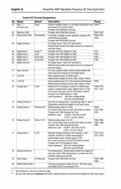
Control I/O Terminal Designations
No. Signal Default Description Param.01 Stop (1) /
Function LossCoast Factory installed jumper or a normally closed input must
be present for the drive to start. Program with P036 [Start Source].
P036 (1)
02 Start/Run FWD – Program with P036 [Start Source]. P036, P03703 Direction/Run REV Rev Enabled To enable or disable reverse operation, program with
A166 [Reverse Disable].Program with P036 [Start Source].
P036, P037, A166
04 Digital Common – For digital inputs. Tied to I/O Terminal 09.Electronically isolated with digital inputs from analog I/O and opto output.
05 Digital Input 1 Purge (2) Program with T051 [Digital In1 Sel]. T05106 Digital Input 2 Local Program with T052 [Digital In2 Sel]. T05207 Digital Input 3 Clear Fault Program with T053 [Digital In3 Sel]. T05308 Digital Input 4 Comm Port Program with T054 [Digital In4 Sel]. T05409 Digital Common – For digital inputs. Tied to I/O Terminal 04.
Electronically isolated with digital inputs from analog I/O and opto output.
10 Opto Common – For opto-coupled outputs. Electronically isolated with opto output from analog I/O and digital inputs.
11 +24V DC – Drive supplied power for digital inputs.Referenced to Digital Common. Max. Output: 100mA.
12 +10V DC – Drive supplied power for 0-10V external potentiometer.Referenced to Analog Common. Max. Output: 15mA.
P038
13 Analog Input 1 0-10V External 0-10V (unipolar), 0-20mA or 4-20mA input supply or potentiometer wiper. Default input is 0-10V.For current (mA) input, set AI1 DIP Switch to 20mA. Program with T069 [Analog In 1 Sel].Input Impedance: 100k ohm (Voltage Mode)
250 ohm (Current Mode)
T069, T070, T071, T072
14 Analog Common 1 – Common for Analog Input 1 and Analog Output 1 and 2. Electrically isolated from digital I/O and opto output.
15 Analog Output 1 OutFreq 0-10 Default analog output is 0-10V.For current (mA) value, set AO1 DIP Switch to 20mA. Program with T082 [Analog Out1 Sel].Maximum Load: 4-20mA = 525 ohm (10.5V)
0-10V = 1k ohm (10mA)
P038, T051-T054, A152
16 Analog Output 2 OutCurr 0-10 Default analog output is 0-10V.For a current (mA) value, set AO2 DIP Switch to 20mA. Program with T085 [Analog Out2 Sel].Maximum Load: 4-20mA = 525 ohm (10.5V)
0-10V = 1k ohm (10mA)
T082, T084, T085, T086, T087
17 Analog Input 2 0-10V Optically isolated external 0-10V (unipolar), ±10V (bipolar), 0-20mA or 4-20mA input supply or potentiometer wiper. Default input is 0-10V.For current (mA) input, set AI2 DIP Switch to 20mA. Program with T073 [Analog In 2 Sel].Input Impedance: 100k ohm (Voltage Mode)
250 ohm (Current Mode)
T073, T074, T075, T076
18 Analog Common 2 – For Analog Input 2. Electronically isolated from digital I/O and opto output. With Analog Input 2, provides one fully isolated analog input channel.
19 Opto Output At Frequency Program with T065 [Opto Out Sel]. T065, T066, T068
20 RS485 (DSI) Shield – Terminal connected to Safety Ground - PE when using the RS485 (DSI) Communication Port.
(1) See Footnotes (1) and (4) on previous page.(2) See the User Manual for Important information regarding Stop commands and the [Digital Inx Sel] Purge option.
PowerFlex 400P Adjustable Frequency AC Drive Quick Start English-13
22P-QS001C-EN-P.fm Page 13 Thursday, March 30, 2017 5:55 PM
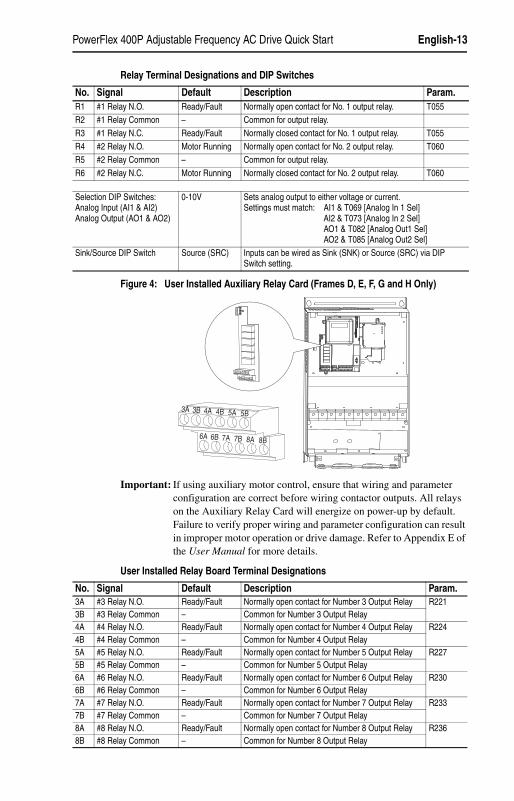
Relay Terminal Designations and DIP Switches
Figure 4: User Installed Auxiliary Relay Card (Frames D, E, F, G and H Only)
Important: If using auxiliary motor control, ensure that wiring and parameter configuration are correct before wiring contactor outputs. All relays on the Auxiliary Relay Card will energize on power-up by default. Failure to verify proper wiring and parameter configuration can result in improper motor operation or drive damage. Refer to Appendix E of the User Manual for more details.
User Installed Relay Board Terminal Designations
No. Signal Default Description Param.R1 #1 Relay N.O. Ready/Fault Normally open contact for No. 1 output relay. T055R2 #1 Relay Common – Common for output relay.R3 #1 Relay N.C. Ready/Fault Normally closed contact for No. 1 output relay. T055R4 #2 Relay N.O. Motor Running Normally open contact for No. 2 output relay. T060R5 #2 Relay Common – Common for output relay.R6 #2 Relay N.C. Motor Running Normally closed contact for No. 2 output relay. T060
Selection DIP Switches:Analog Input (AI1 & AI2)Analog Output (AO1 & AO2)
0-10V Sets analog output to either voltage or current.Settings must match: AI1 & T069 [Analog In 1 Sel]
AI2 & T073 [Analog In 2 Sel]AO1 & T082 [Analog Out1 Sel]AO2 & T085 [Analog Out2 Sel]
Sink/Source DIP Switch Source (SRC) Inputs can be wired as Sink (SNK) or Source (SRC) via DIP Switch setting.
3A 3B 4A 4B 5A 5B
6A 6B 7A 7B 8A 8B
No. Signal Default Description Param.3A #3 Relay N.O. Ready/Fault Normally open contact for Number 3 Output Relay R2213B #3 Relay Common – Common for Number 3 Output Relay4A #4 Relay N.O. Ready/Fault Normally open contact for Number 4 Output Relay R2244B #4 Relay Common – Common for Number 4 Output Relay5A #5 Relay N.O. Ready/Fault Normally open contact for Number 5 Output Relay R2275B #5 Relay Common – Common for Number 5 Output Relay6A #6 Relay N.O. Ready/Fault Normally open contact for Number 6 Output Relay R2306B #6 Relay Common – Common for Number 6 Output Relay7A #7 Relay N.O. Ready/Fault Normally open contact for Number 7 Output Relay R2337B #7 Relay Common – Common for Number 7 Output Relay8A #8 Relay N.O. Ready/Fault Normally open contact for Number 8 Output Relay R2368B #8 Relay Common – Common for Number 8 Output Relay
English-14 PowerFlex 400P Adjustable Frequency AC Drive Quick Start
22P-QS001C-EN-P.fm Page 14 Thursday, March 30, 2017 5:55 PM
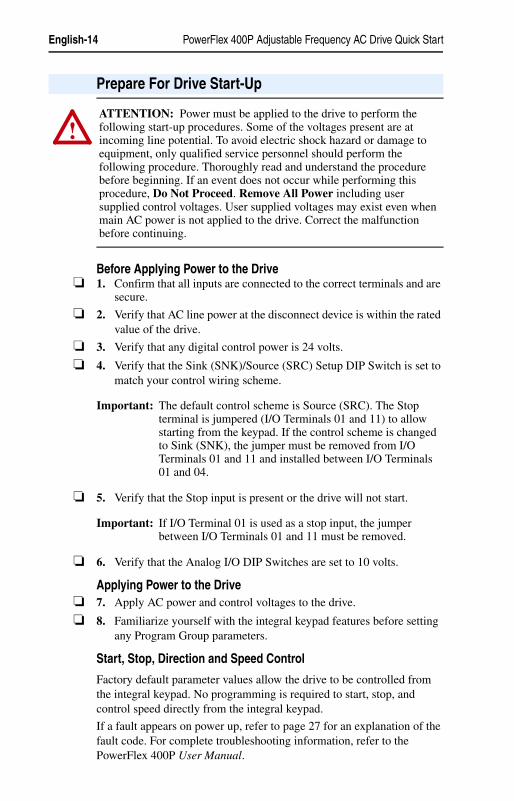
Before Applying Power to the Drive❏ 1. Confirm that all inputs are connected to the correct terminals and are
secure.
❏ 2. Verify that AC line power at the disconnect device is within the rated value of the drive.
❏ 3. Verify that any digital control power is 24 volts.
❏ 4. Verify that the Sink (SNK)/Source (SRC) Setup DIP Switch is set to match your control wiring scheme.
Important: The default control scheme is Source (SRC). The Stop terminal is jumpered (I/O Terminals 01 and 11) to allow starting from the keypad. If the control scheme is changed to Sink (SNK), the jumper must be removed from I/O Terminals 01 and 11 and installed between I/O Terminals 01 and 04.
❏ 5. Verify that the Stop input is present or the drive will not start.
Important: If I/O Terminal 01 is used as a stop input, the jumper between I/O Terminals 01 and 11 must be removed.
❏ 6. Verify that the Analog I/O DIP Switches are set to 10 volts.
Applying Power to the Drive❏ 7. Apply AC power and control voltages to the drive.
❏ 8. Familiarize yourself with the integral keypad features before setting any Program Group parameters.
Start, Stop, Direction and Speed Control
Factory default parameter values allow the drive to be controlled from the integral keypad. No programming is required to start, stop, and control speed directly from the integral keypad.
If a fault appears on power up, refer to page 27 for an explanation of the fault code. For complete troubleshooting information, refer to the PowerFlex 400P User Manual.
Prepare For Drive Start-Up
!ATTENTION: Power must be applied to the drive to perform the following start-up procedures. Some of the voltages present are at incoming line potential. To avoid electric shock hazard or damage to equipment, only qualified service personnel should perform the following procedure. Thoroughly read and understand the procedure before beginning. If an event does not occur while performing this procedure, Do Not Proceed. Remove All Power including user supplied control voltages. User supplied voltages may exist even when main AC power is not applied to the drive. Correct the malfunction before continuing.

PowerFlex 400P Adjustable Frequency AC Drive Quick Start English-15
22P-QS001C-EN-P.fm Page 15 Thursday, March 30, 2017 5:55 PM
Operator Keys
Integral Keypad
Key Name DescriptionEscape Back one step in programming menu.
Cancel a change to a parameter value and exit Program Mode.
Select Advance one step in programming menu.Select a digit when viewing parameter value.
Up ArrowDown Arrow
Scroll through groups and parameters.Increase/decrease the value of a flashing digit.
Enter Advance one step in programming menu.Save a change to a parameter value.
Digital Speed Increment andDecrement Arrows
Used to control speed of drive. Default is active.Control is activated by parameter P038 [Speed Reference].
Start(1) Used to start the drive. Default is active.Control is activated by parameter P036 [Start Source].
Reverse (1) Used to reverse direction of the drive. Default is active.Controlled by parameters P036 [Start Source] and A166 [Reverse Disable].
Stop Used to stop the drive or clear a fault.This key is always active.Controlled by parameter P037 [Stop Mode].
(1) Important: Certain digital input settings can override drive operation. Refer to “Start and Speed Reference Control” on page 1-29 of the User Manual for details.
English-16 PowerFlex 400P Adjustable Frequency AC Drive Quick Start
22P-QS001C-EN-P.fm Page 16 Thursday, March 30, 2017 5:55 PM
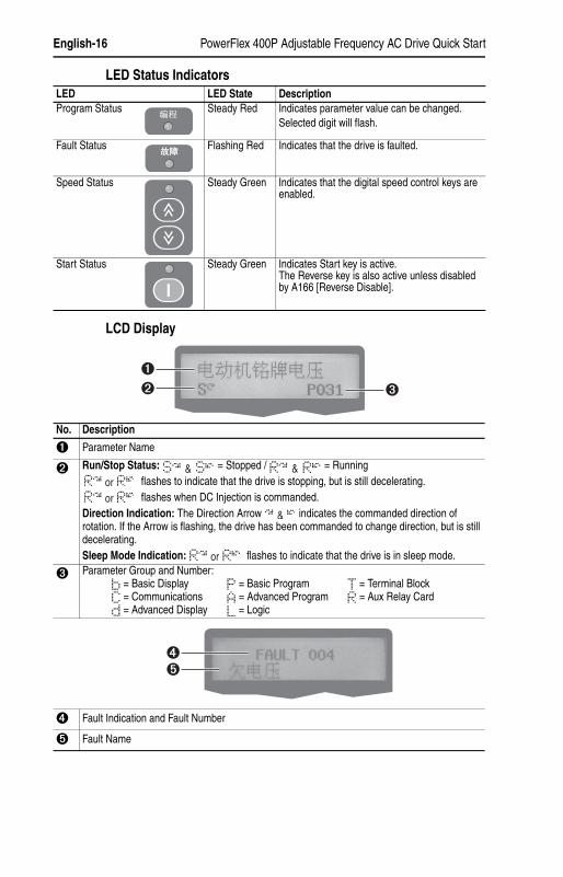
LED Status Indicators
LCD Display
LED LED State DescriptionProgram Status Steady Red Indicates parameter value can be changed.
Selected digit will flash.
Fault Status Flashing Red Indicates that the drive is faulted.
Speed Status Steady Green Indicates that the digital speed control keys are enabled.
Start Status Steady Green Indicates Start key is active.The Reverse key is also active unless disabled by A166 [Reverse Disable].
No. Description
➊ Parameter Name
➋ Run/Stop Status: = Stopped / = Running flashes to indicate that the drive is stopping, but is still decelerating. flashes when DC Injection is commanded.
Direction Indication: The Direction Arrow indicates the commanded direction of rotation. If the Arrow is flashing, the drive has been commanded to change direction, but is still decelerating.Sleep Mode Indication: flashes to indicate that the drive is in sleep mode.
➌ Parameter Group and Number:= Basic Display = Basic Program = Terminal Block= Communications = Advanced Program = Aux Relay Card= Advanced Display = Logic
➍ Fault Indication and Fault Number
➎ Fault Name
➊➋ ➌
➍➎
PowerFlex 400P Adjustable Frequency AC Drive Quick Start English-17
22P-QS001C-EN-P.fm Page 17 Thursday, March 30, 2017 5:55 PM
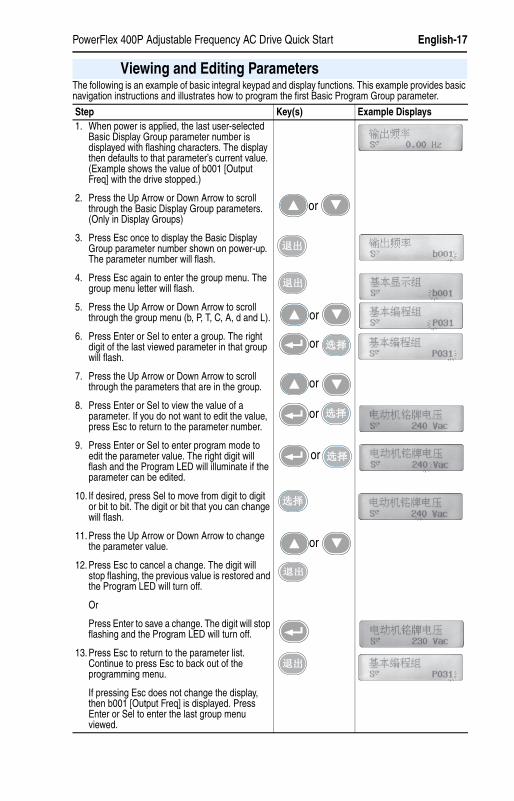
The following is an example of basic integral keypad and display functions. This example provides basic navigation instructions and illustrates how to program the first Basic Program Group parameter.
Viewing and Editing Parameters
Step Key(s) Example Displays1. When power is applied, the last user-selected
Basic Display Group parameter number is displayed with flashing characters. The display then defaults to that parameter’s current value. (Example shows the value of b001 [Output Freq] with the drive stopped.)
2. Press the Up Arrow or Down Arrow to scroll through the Basic Display Group parameters. (Only in Display Groups)
3. Press Esc once to display the Basic Display Group parameter number shown on power-up. The parameter number will flash.
4. Press Esc again to enter the group menu. The group menu letter will flash.
5. Press the Up Arrow or Down Arrow to scroll through the group menu (b, P, T, C, A, d and L).
6. Press Enter or Sel to enter a group. The right digit of the last viewed parameter in that group will flash.
7. Press the Up Arrow or Down Arrow to scroll through the parameters that are in the group.
8. Press Enter or Sel to view the value of a parameter. If you do not want to edit the value, press Esc to return to the parameter number.
9. Press Enter or Sel to enter program mode to edit the parameter value. The right digit will flash and the Program LED will illuminate if the parameter can be edited.
10. If desired, press Sel to move from digit to digit or bit to bit. The digit or bit that you can change will flash.
11. Press the Up Arrow or Down Arrow to change the parameter value.
12. Press Esc to cancel a change. The digit will stop flashing, the previous value is restored and the Program LED will turn off.
Or
Press Enter to save a change. The digit will stop flashing and the Program LED will turn off.
13. Press Esc to return to the parameter list. Continue to press Esc to back out of the programming menu.
If pressing Esc does not change the display, then b001 [Output Freq] is displayed. Press Enter or Sel to enter the last group menu viewed.
or
or
or
or
or
or
or

English-18 PowerFlex 400P Adjustable Frequency AC Drive Quick Start
22P-QS001C-EN-P.fm Page 18 Thursday, March 30, 2017 5:55 PM
The Basic Program Group contains the most commonly changed parameters.
The PowerFlex 400P is designed so that start up is simple and efficient. The Program Group contains the most commonly used parameters.
Basic Display Group Parameters
No. Parameter Min/Max Display/Optionsb001 [Output Freq] 0.00/ [Maximum Freq] 0.01 Hz
b002 [Commanded Freq] 0.00/ [Maximum Freq] 0.01 Hz
b003 [Output Current] 0.0/(Drive Amps × 2) 0.1 Amps
b004 [Output Voltage] 0/510 1 VAC
b005 [DC Bus Voltage] 0/820 1 VDC
b006 [Drive Status] 0/1 (1 = Condition True) Bit 4 Bit 3 Bit 2 Bit 1Decelerating Accelerating Forward Running
b007 [Fault 1 Code] 0/122 1
b008 [Process Display] 0.00/9999.99 0.01
b010 [Output Power] 0.0/999.9 kW 0.1 kW
b011 [Elapsed MWh] 0/3276.7 MWh 0.1 MWh
b012 [Elapsed Run Time] 0/9999 Hrs 1 = 10 Hrs
b013 [Torque Current] 0.0/(Drive Amps × 2) 0.1 Amps
b014 [Drive Temp] 0/120 degC 1 degC
b015 [Elapsed kWh] 0.0/100.0 kWh 0.1 kWh
Smart Start-Up with Basic Program Group
= Stop drive before changing this parameter.
No. Parameter Min/Max Display/Options DefaultP031 [Motor NP Volts] 20/Drive Rated Volts 1 VAC Based on Drive Rating
Set to the motor nameplate rated volts.
P032 [Motor NP Hertz] 15/320 Hz 1 Hz 60 Hz
Set to the motor nameplate rated frequency.
P033 [Motor OL Current] 0.0/(Drive Amps × 2) 0.1 Amps Based on Drive Rating
Set to the maximum allowable motor current.
P034 [Minimum Freq] 0.0/320.0 Hz 0.1 Hz 0.0 Hz
Sets the lowest frequency the drive will output continuously.
P035 [Maximum Freq] 0.0/320.0 Hz 0.1 Hz 60.0 Hz
Sets the highest frequency the drive will output.
P036 [Start Source] 0/6 0 = “Keypad” 4 = “2-W Hi Speed”1 = “3-Wire” 5 = “Comm Port”2 = “2-Wire” 6 = “2-W Lvl/Enbl”3 = “2-W Lvl Sens”
3
Sets the control scheme used to start the drive.
P037 [Stop Mode] 0/7 0 = “Ramp, CF”(1)
1 = “Coast, CF”(1)
2 = “DC Brake, CF”(1)
3 = “DCBrkAuto,CF”(1)
4 = “Ramp”5 = “Coast”6 = “DC Brake”7 = “DC BrakeAuto”(1) Stop input also clears active fault.
0
Active stop mode for all stop sources [e.g. keypad, run forward (I/O Terminal 02), run reverse (I/O Terminal 03), RS485 port] except as noted below.Important: I/O Terminal 01 is always a coast to stop input except when P036 [Start Source] is set for “3-Wire” control. When in three wire control, I/O Terminal 01 is controlled by P037 [Stop Mode].
PowerFlex 400P Adjustable Frequency AC Drive Quick Start English-19
22P-QS001C-EN-P.fm Page 19 Thursday, March 30, 2017 5:55 PM
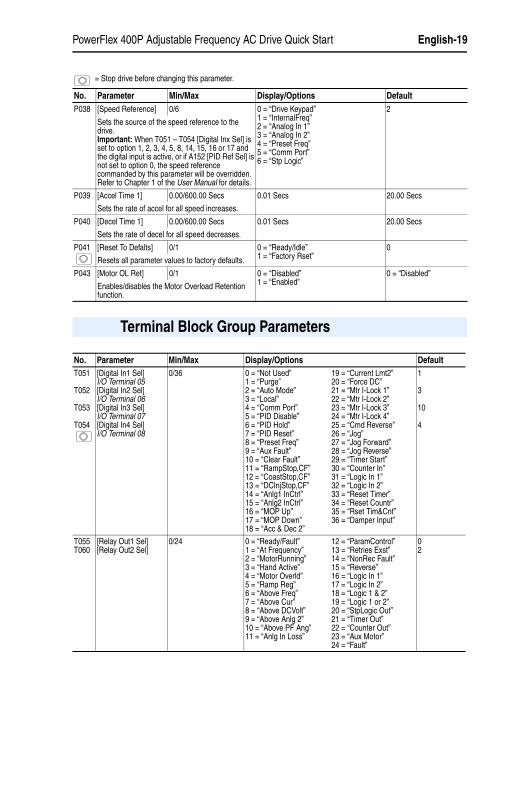
P038 [Speed Reference] 0/6 0 = “Drive Keypad”1 = “InternalFreq”2 = “Analog In 1”3 = “Analog In 2”4 = “Preset Freq”5 = “Comm Port”6 = “Stp Logic”
2
Sets the source of the speed reference to the drive.Important: When T051 – T054 [Digital Inx Sel] is set to option 1, 2, 3, 4, 5, 8, 14, 15, 16 or 17 and the digital input is active, or if A152 [PID Ref Sel] is not set to option 0, the speed reference commanded by this parameter will be overridden. Refer to Chapter 1 of the User Manual for details.
P039 [Accel Time 1] 0.00/600.00 Secs 0.01 Secs 20.00 Secs
Sets the rate of accel for all speed increases.
P040 [Decel Time 1] 0.00/600.00 Secs 0.01 Secs 20.00 Secs
Sets the rate of decel for all speed decreases.
P041 [Reset To Defalts] 0/1 0 = “Ready/Idle”1 = “Factory Rset”
0
Resets all parameter values to factory defaults.
P043 [Motor OL Ret] 0/1 0 = “Disabled”1 = “Enabled”
0 = “Disabled”
Enables/disables the Motor Overload Retention function.
= Stop drive before changing this parameter.
No. Parameter Min/Max Display/Options Default
Terminal Block Group Parameters
No. Parameter Min/Max Display/Options DefaultT051
T052
T053
T054
[Digital In1 Sel]I/O Terminal 05[Digital In2 Sel]I/O Terminal 06[Digital In3 Sel]I/O Terminal 07[Digital In4 Sel]I/O Terminal 08
0/36 0 = “Not Used”1 = “Purge”2 = “Auto Mode”3 = “Local”4 = “Comm Port”5 = “PID Disable”6 = “PID Hold”7 = “PID Reset”8 = “Preset Freq”9 = “Aux Fault”10 = “Clear Fault”11 = “RampStop,CF”12 = “CoastStop,CF”13 = “DCInjStop,CF”14 = “Anlg1 InCtrl”15 = “Anlg2 InCtrl”16 = “MOP Up”17 = “MOP Down”18 = “Acc & Dec 2”
19 = “Current Lmt2”20 = “Force DC”21 = “Mtr I-Lock 1”22 = “Mtr I-Lock 2”23 = “Mtr I-Lock 3”24 = “Mtr I-Lock 4”25 = “Cmd Reverse”26 = “Jog”27 = “Jog Forward”28 = “Jog Reverse”29 = “Timer Start”30 = “Counter In”31 = “Logic In 1”32 = “Logic In 2”33 = “Reset Timer”34 = “Reset Countr”35 = “Rset Tim&Cnt”36 = “Damper Input”
1
3
10
4
T055T060
[Relay Out1 Sel][Relay Out2 Sel]
0/24 0 = “Ready/Fault”1 = “At Frequency”2 = “MotorRunning”3 = “Hand Active”4 = “Motor Overld”5 = “Ramp Reg”6 = “Above Freq”7 = “Above Cur”8 = “Above DCVolt”9 = “Above Anlg 2”10 = “Above PF Ang”11 = “Anlg In Loss”
12 = “ParamControl”13 = “Retries Exst”14 = “NonRec Fault”15 = “Reverse”16 = “Logic In 1”17 = “Logic In 2”18 = “Logic 1 & 2”19 = “Logic 1 or 2”20 = “StpLogic Out”21 = “Timer Out”22 = “Counter Out”23 = “Aux Motor”24 = “Fault”
02
English-20 PowerFlex 400P Adjustable Frequency AC Drive Quick Start
22P-QS001C-EN-P.fm Page 20 Thursday, March 30, 2017 5:55 PM
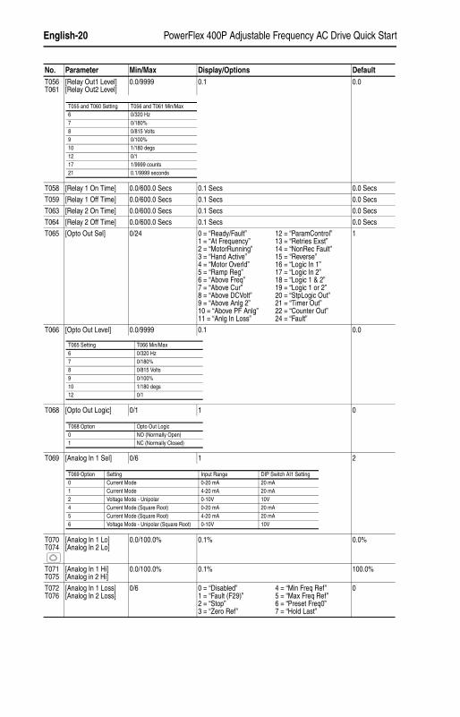
T056T061
[Relay Out1 Level][Relay Out2 Level]
0.0/9999 0.1 0.0
T058 [Relay 1 On Time] 0.0/600.0 Secs 0.1 Secs 0.0 Secs
T059 [Relay 1 Off Time] 0.0/600.0 Secs 0.1 Secs 0.0 Secs
T063 [Relay 2 On Time] 0.0/600.0 Secs 0.1 Secs 0.0 Secs
T064 [Relay 2 Off Time] 0.0/600.0 Secs 0.1 Secs 0.0 Secs
T065 [Opto Out Sel] 0/24 0 = “Ready/Fault”1 = “At Frequency”2 = “MotorRunning”3 = “Hand Active”4 = “Motor Overld”5 = “Ramp Reg”6 = “Above Freq”7 = “Above Cur”8 = “Above DCVolt”9 = “Above Anlg 2”10 = “Above PF Anlg”11 = “Anlg In Loss”
12 = “ParamControl”13 = “Retries Exst”14 = “NonRec Fault”15 = “Reverse”16 = “Logic In 1”17 = “Logic In 2”18 = “Logic 1 & 2”19 = “Logic 1 or 2”20 = “StpLogic Out”21 = “Timer Out”22 = “Counter Out”24 = “Fault”
1
T066 [Opto Out Level] 0.0/9999 0.1 0.0
T068 [Opto Out Logic] 0/1 1 0
T069 [Analog In 1 Sel] 0/6 1 2
T070T074
[Analog In 1 Lo][Analog In 2 Lo]
0.0/100.0% 0.1% 0.0%
T071T075
[Analog In 1 Hi][Analog in 2 Hi]
0.0/100.0% 0.1% 100.0%
T072T076
[Analog In 1 Loss][Analog In 2 Loss]
0/6 0 = “Disabled”1 = “Fault (F29)”2 = “Stop”3 = “Zero Ref”
4 = “Min Freq Ref”5 = “Max Freq Ref”6 = “Preset Freq0”7 = “Hold Last”
0
No. Parameter Min/Max Display/Options Default
T055 and T060 Setting T056 and T061 Min/Max6 0/320 Hz7 0/180%8 0/815 Volts9 0/100%10 1/180 degs12 0/117 1/9999 counts21 0.1/9999 seconds
T065 Setting T066 Min/Max6 0/320 Hz7 0/180%8 0/815 Volts9 0/100%10 1/180 degs12 0/1
T068 Option Opto Out Logic0 NO (Normally Open)1 NC (Normally Closed)
T069 Option Setting Input Range DIP Switch AI1 Setting0 Current Mode 0-20 mA 20 mA1 Current Mode 4-20 mA 20 mA2 Voltage Mode - Unipolar 0-10V 10V4 Current Mode (Square Root) 0-20 mA 20 mA5 Current Mode (Square Root) 4-20 mA 20 mA6 Voltage Mode - Unipolar (Square Root) 0-10V 10V

PowerFlex 400P Adjustable Frequency AC Drive Quick Start English-21
22P-QS001C-EN-P.fm Page 21 Thursday, March 30, 2017 5:55 PM
T073 [Analog In 2 Sel] 0/7 1 2
T077 [Sleep-Wake Sel] 0/4 0 = “Disabled”1 = “Analog In 1”
2 = “Analog In 2”3 = “Command Freq”4 = “Ind Slp Wake”
0
T078 [Sleep Level] 0.0/100.0% 0.1% 10.0%
T079 [Sleep Time] 0.0/600.0 Secs 0.1 Secs 0.0 Secs
T080 [Wake Level] 0.0/100.0% 0.1% 15.0%
T081 [Wake Time] 0.0/600.0 Secs 0.1 Secs 0.0 Secs
T082T085
[Analog Out1 Sel][Analog Out2 Sel]
0/29 1 01
T083T086
[Analog Out1 High][Analog Out2 High]
0/800% 1% 100%
T084T087
[Anlg Out1 Setpt][Anlg Out2 Setpt]
0.0/100.0% 0.1% 0.0%
T088 [Anlg Loss Delay] 0.0/20.0 Secs 0.1 Secs 0.0 Secs
T089 [Analog In Filter] 0/14 1 0
T090 [Sleep Sel] 0/7 0 = “AI1 > SlpLvl”1 = “AI1 < SlpLvl”2 = “AI2 > SlpLvl”3 = “AI2 < SlpLvl”
4 = “OFrq>SlpLvl”5 = “OFrq<SlpLvl”6 = “CFrq>SlpLvl”7 = “CFrq<SlpLvl”
0
No. Parameter Min/Max Display/Options Default
T073 Option Setting Input Range DIP Switch AI2 Setting0 Current Mode 0-20 mA 20 mA1 Current Mode 4-20 mA 20 mA2 Voltage Mode - Unipolar 0-10V 10V3 Voltage Mode - Bipolar -10 to +10V 10V4 Current Mode (Square Root) 0-20 mA 20 mA5 Current Mode (Square Root) 4-20 mA 20 mA6 Voltage Mode - Unipolar (Square Root) 0-10V 10V7 Voltage Mode - Bipolar (Square Root) -10 to +10V 10V
SettingOutput Range Min. Output Value Max. Output Value Filter
DIP Switch AO1
Related Parameter
0 OutFreq 0-10 0-10V 0V = 0 Hz [Maximum Frequency] None 10V b0011 OutCurr 0-10 0-10V 0V = 0 Amps 200% Drive Rated FLA Filter A 10V b0032 OutTorq 0-10 0-10V 0V = 0 Amps 200% Drive Rated FLA Filter A 10V b0133 OutVolt 0-10 0-10V 0V = 0 Volts 120% Drive Rated Output V None 10V b0044 OutPowr 0-10 0-10V 0V = 0 kW 200% Drive Rated Power Filter A 10V b0105 Setpnt 0-10 0-10V 0V = 0.0% 100.0% Setpoint Setting None 10V T0846 TstData 0-10 0-10V 0V = 0000 65535 (Hex FFFF) None 10V A1967 OutFreq 0-20 0-20 mA 0 mA = 0 Hz [Maximum Frequency] None 20 mA b0018 OutCurr 0-20 0-20 mA 0 mA = 0 Amps 200% Drive Rated FLA Filter A 20 mA b0039 OutTorq 0-20 0-20 mA 0 mA = 0 Amps 200% Drive Rated FLA Filter A 20 mA b01310 OutVolt 0-20 0-20 mA 0 mA = 0 Volts 120% Drive Rated Output V None 20 mA b00411 OutPowr 0-20 0-20 mA 0 mA = 0 kW 200% Drive Rated Power Filter A 20 mA b01012 Setpnt 0-20 0-20 mA 0 mA = 0.0% 100.0% Setpoint Setting None 20 mA T08413 TstData 0-20 0-20 mA 0 mA = 0000 65535 (Hex FFFF) None 20 mA A19614 OutFreq 4-20 4-20 mA 4 mA = 0 Hz [Maximum Frequency] None 20 mA b00115 OutCurr 4-20 4-20 mA 4 mA = 0 Amps 200% Drive Rated FLA Filter A 20 mA b00316 OutTorq 4-20 4-20 mA 4 mA = 0 Amps 200% Drive Rated FLA Filter A 20 mA b01317 OutVolt 4-20 4-20 mA 4 mA = 0 Volts 120% Drive Rated Output V None 20 mA b00418 OutPowr 4-20 4-20 mA 4 mA = 0 kW 200% Drive Rated Power Filter A 20 mA b01019 Setpnt 4-20 4-20 mA 4 mA = 0.0% 100.0% Setpoint Setting None 20 mA T08420 TstData 4-20 4-20 mA 4 mA = 0000 65535 (Hex FFFF) None 20 mA A19621 MinFreq 0-10 0-10V 0 V = [Minimum Freq] [Maximum Freq] None 10 V P03422 MinFreq 0-20 0-20 mA 0 mA = [Minimum Freq] [Maximum Freq] None 20 mA P03423 MinFreq 4-20 4-20 mA 4 mA = [Minimum Freq] [Maximum Freq] None 20 mA P03424 AnlgIn1 0-10 0-10V 0V = 0.0% 100.0% Setting Filter A 10V d30525 AnlgIn1 0-20 0-20 mA 0 mA = 0.0% 100.0% Setting Filter A 20 mA d30526 AnlgIn1 4-20 4-20 mA 4 mA = 0.0% 100.0% Setting Filter A 20 mA d30527 AnlgIn2 0-10 0-10V 0V = 0.0% 100.0% Setting Filter A 10V d30628 AnlgIn2 0-20 0-20 mA 0 mA = 0.0% 100.0% Setting Filter A 20 mA d30629 AnlgIn2 4-20 4-20 mA 4 mA = 0.0% 100.0% Setting Filter A 20 mA d306
T083 Setting T082 Setting T082 Max. Output Value50% 1 “OutCurr 0-10” 5V for 200% Drive Rated Output Current90% 11 “OutPowr 0-20” 18 mA for 200% Drive Rated Power
English-22 PowerFlex 400P Adjustable Frequency AC Drive Quick Start
22P-QS001C-EN-P.fm Page 22 Thursday, March 30, 2017 5:55 PM
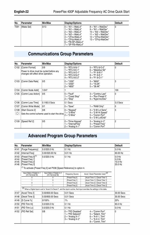
T091 [Wake Sel] 0/13 0 = “AI1 > WakLvl”1 = “AI1 < WakLvl”2 = “AI2 > WakLvl”3 = “AI2 < WakLvl”4 = “CFrq>WakLvl”5 = “CFrq<WakLvl”6 = “FB-SP>WakLvl”7 = “SP-FB>WakLvl”
8 = “AI1 > WakDev”9 = “AI1 < WakDev”10 = “AI2 > WakDev”11 = “AI2 < WakDev”12 = “CFrq>WakDev”13 = “CFrq<WakDev”
0
No. Parameter Min/Max Display/Options Default
Communications Group Parameters
No. Parameter Min/Max Display/Options DefaultC102 [Comm Format] 0/9 0 = “RTU 8-N-1”
1 = “RTU 8-E-1”2 = “RTU 8-O-1”3 = “RTU 8-N-2”4 = “RTU 8-E-2”
5 = “RTU 8-O-2”6 = “MetaSys N2”7 = “P1 8-N-1”8 = “P1 8-E-1”9 = “P1 8-O-1”
0
Power to drive must be cycled before any changes will affect drive operation.
C103 [Comm Data Rate] 0/5 0 = “1200”1 = “2400”2 = “4800”
3 = “9600”4 = “19.2K”5 = “38.4K”
3
C104 [Comm Node Addr] 1/247 1 100
C105 [Comm Loss Action] 0/5 0 = “Fault”1 = “Coast Stop”2 = “Stop”
3 = “Continu Last”4 = “Run Preset 0”5 = “Kypd Inc/Dec”
0
C106 [Comm Loss Time] 0.1/60.0 Secs 0.1 Secs 5.0 Secs
C107 [Comm Write Mode] 0/1 0 = “Save” 1 = “RAM Only” 0
C108 [Start Source 2] 0/6 0 = “Keypad”1 = “3-Wire”2 = “2-Wire”
3 = “2-W Lvl Sens”4 = “2-W Hi Speed”5 = “Comm Port”6 = “2-W Lvl/Enbl”
3
Sets the control scheme used to start the drive.
C109 [Speed Ref 2] 0/5 0 = “Drive Keypad”1 = “InternalFreq”2 = “Analog In 1”
3 = “Analog In 2”4 = “Preset Freq”5 = “Comm Port”
2
Advanced Program Group Parameters
No. Parameter Min/Max Display/Options DefaultA141 [Purge Frequency] 0.0/320.0 Hz 0.1 Hz 5.0 Hz
A142 [Internal Freq] 0.00/320.00 Hz 0.01 Hz 60.00 Hz
A143A144A145A146
[Preset Freq 0](1)
[Preset Freq 1][Preset Freq 2][Preset Freq 3]
0.0/320.0 Hz 0.1 Hz 0.0 Hz5.0 Hz10.0 Hz20.0 Hz
(1) To activate [Preset Freq 0] set P038 [Speed Reference] to option 4.
A147 [Accel Time 2] 0.00/600.00 Secs 0.01 Secs 30.00 Secs
A148 [Decel Time 2] 0.00/600.00 Secs 0.01 Secs 30.00 Secs
A149 [S Curve %] 0/100% 1% 20%
A150 [PID Trim Hi] 0.0/320.0 Hz 0.1 Hz 60.0 Hz
A151 [PID Trim Lo] 0.0/320.0 Hz 0.1 Hz 0.0 Hz
A152 [PID Ref Sel] 0/8 0 = “PID Disabled”1 = “PID Setpoint”2 = “Analog In 1”3 = “Analog In 2”
4 = “Comm Port”5 = “Setpnt, Trim”6 = “A-In 1, Trim”7 = “A-In 2, Trim”8 = “Comm, Trim”
0
Input State of Digital In 1(I/O Terminal 05)
Input State of Digital In 2(I/O Terminal 06) Frequency Source Accel / Decel Parameter Used (2)
0 0 [Preset Freq 0] [Accel Time 1] / [Decel Time 1]1 0 [Preset Freq 1] [Accel Time 1] / [Decel Time 1]0 1 [Preset Freq 2] [Accel Time 2] / [Decel Time 2]1 1 [Preset Freq 3] [Accel Time 2] / [Decel Time 2]
(2) When a Digital Input is set to “Accel 2 & Decel 2”, and the input is active, that input overrides the settings in this table.
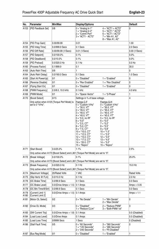
PowerFlex 400P Adjustable Frequency AC Drive Quick Start English-23
22P-QS001C-EN-P.fm Page 23 Thursday, March 30, 2017 5:55 PM
A153 [PID Feedback Sel] 0/8 0 = “Analog In 1”1 = “Analog In 2”2 = “Comm Port”3 = “ACT1 - ACT2”
4 = “ACT1 + ACT2”5 = “ACT1 * ACT2”6 = “ACT1 / ACT2”7 = “Min A1, A2”8 = “Max A1, A2”
0
A154 [PID Prop Gain] 0.00/99.99 0.01 1.00
A155 [PID Integ Time] 0.0/999.9 Secs 0.1 Secs 2.0 Secs
A156 [PID Diff Rate] 0.00/99.99 (1/Secs) 0.01 (1/Secs) 0.00 (1/Secs)
A157 [PID Setpoint] 0.0/100.0% 0.1% 0.0%
A158 [PID Deadband] 0.0/10.0% 0.1% 0.0%
A159 [PID Preload] 0.0/320.0 Hz 0.1 Hz 0.0 Hz
A160 [Process Factor] 0.1/999.9 0.1 30.0
A163 [Auto Rstrt Tries] 0/9 1 0
A164 [Auto Rstrt Delay] 0.0/160.0 Secs 0.1 Secs 1.0 Secs
A165 [Start At PowerUp] 0/1 0 = “Disabled” 1 = “Enabled” 0
A166 [Reverse Disable] 0/1 0 = “Rev Enabled” 1 = “Rev Disabled” 0
A167 [Flying Start En] 0/1 0 = “Disabled” 1 = “Enabled” 0
A168 [PWM Frequency] 2.0/8.0, 10.0 kHz 0.1 kHz 4.0 kHz
A169 [PWM Mode] 0/1 0 = “Space Vector” 1 = “2-Phase” 1
A170 [Boost Select] 0/15 Settings in % of base voltage. 4
Only active when A125 [Torque Perf Mode] is set to 0 “V/Hz”.
Frames C-F Frames G-H0 = “Custom V/Hz” 0 = “Custom V/Hz”1 = “30.0, VT” 1 = “30.0, VT”2 = “35.0, VT” 2 = “35.0, VT”3 = “40.0, VT” 3 = “40.0, VT”4 = “45.0, VT” 4 = “45.0, VT”5 = “0.0, no IR” 5 = “0.0, no IR”6 = “0.0” 6 = “0.0”7 = “2.5, CT” 7 = “0.2”8 = “5.0, CT” 8 = “0.5”9 = “7.5, CT” 9 = “0.8”10 = “10.0, CT” 10 = “1.0”11 = “12.5, CT” 11 = “2.0”12 = “15.0, CT” 12 = “3.0”13 = “17.5, CT” 13 = “4.0”14 = “20.0, CT” 14 = “5.0”15 = “Kepco” 15 = “Kepco”
A171 [Start Boost] 0.0/25.0% 1.1% 2.5%
Only active when A170 [Boost Select] and L361 [Torque Perf Mode] are set to “0”.
A172 [Break Voltage] 0.0/100.0% 0.1% 25.0%
Only active when A170 [Boost Select] and L361 [Torque Perf Mode] are set to “0”.
A173 [Break Frequency] 0.0/320.0 Hz 0.1 Hz 15.0 Hz
Only active when A170 [Boost Select] and L361 [Torque Perf Mode] are set to “0”.
A174 [Maximum Voltage] 20/Rated Volts 1 VAC Rated Volts
A175 [Slip Hertz @ FLA] 0.0/10.0 Hz 0.1 Hz 2.0 Hz
A176 [DC Brake Time] 0.0/99.9 Secs 0.1 Secs 0.0 Secs
A177 [DC Brake Level] 0.0/(Drive Amps × 1.5) 0.1 Amps Amps × 0.05
A178 [DC Brk Time@Strt] 0.0/99.9 Secs 0.1 Secs 0.0 Secs
A179A180
[Current Limit 1][Current Limit 2]
0.0/(Drive Amps × 1.5) 0.1 Amps Amps × 1.1
A181 [Motor OL Select] 0/2 0 = “No Derate” 1 = “Min Derate”2 = “Max Derate”
0
A182 [Drive OL Mode] 0/3 0 = “Disabled”1 = “Reduce CLim”
2 = “Reduce PWM”3 = “Both-PWM 1st”
3
A183 [SW Current Trip] 0.0/(Drive Amps × 1.8) 0.1 Amps 0.0 (Disabled)
A184 [Load Loss Level] 0.0/Drive Amps 0.1 Amps 0.0 (Disabled)
A185 [Load Loss Time] 0/9999 Secs 1 Secs 0 (Disabled)
A186 [Stall Fault Time] 0/5 0 = “60 Seconds”1 = “120 Seconds”2 = “240 Seconds”
3 = “360 Seconds”4 = “480 Seconds”5 = “Flt Disabled”
0
A187 [Bus Reg Mode] 0/1 0 = “Disabled” 1 = “Enabled” 1
No. Parameter Min/Max Display/Options Default

English-24 PowerFlex 400P Adjustable Frequency AC Drive Quick Start
22P-QS001C-EN-P.fm Page 24 Thursday, March 30, 2017 5:55 PM
A188 [Skip Frequency 1] 0/320 Hz 1 Hz 0 Hz
A189 [Skip Freq Band 1] 0.0/30.0 Hz 0.1 Hz 0.0 Hz
A190 [Skip Frequency 2] 0/320 Hz 1 Hz 0 Hz
A191 [Skip Freq Band 2] 0.0/30.0 Hz 0.1 Hz 0.0 Hz
A192 [Skip Frequency 3] 0/320 Hz 1 Hz 0 Hz
A193 [Skip Freq Band 3] 0.0/30.0 Hz 0.1 Hz 0.0 Hz
A194 [Compensation] 0/3 0 = “Disabled”1 = “Electrical”
2 = “Mechanical”3 = “Both”
1
A195 [Reset Meters] 0/2 0 = “Ready/Idle” 1 = “Reset MWh”2 = “Reset Time”
0
A196 [Testpoint Sel] 1024/65535 1 1024
A197 [Fault Clear] 0/2 0 = “Ready/Idle” 1 = “Reset Fault”2 = “Clear Buffer”
0
A198 [Program Lock] 0/3 0 = “Unlocked”1 = “Locked” (All)
2 = “Locked” (Not Network)3 = “Locked” (P035, A170)
0
A199 [Motor NP Poles] 2/40 1 4
A200 [Motor NP FLA] 0.1/(Drive Amps × 2) 0.1 Amps Rated Amps
A201 [PID Invert Error] 0/1 0 = “Not Inverted” 1 = “Inverted” 0
A203 [Wake Deviation] 0.0/100.0% 0.1% 0.0%
A204 [ACT1 Input] 0/2 0 = “Analog In 1”1 = “Analog In 2”
2 = “Current” 0
A205 [ACT2 Input] 0/2 0 = “Analog In 1”1 = “Analog In 2”
2 = “Current” 0
A206 [ACT1 Minimum] 0.0/200.0% 0.1% 0.0%
A207 [ACT1 Maximum] 0.0/200.0% 0.1% 100.0%
A208 [ACT2 Minimum] 0.0/200.0% 0.1% 0.0%
A209 [ACT2 Maximum] 0.0/200.0% 0.1% 100.0%
A210 [Wake PID Preload] 0.0/320.0 Hz 0.1 Hz 0.0 Hz(No Preload)
No. Parameter Min/Max Display/Options Default
Aux Relay Card Group Parameters
No. Parameter Min/Max Display/Options DefaultR221R224R227R230R233R236
[Relay Out3 Sel][Relay Out4 Sel][Relay Out5 Sel][Relay Out6 Sel][Relay Out7 Sel][Relay Out8 Sel]
0/24 0 = “Ready/Fault”1 = “At Frequency”2 = “MotorRunning”3 = “Hand Active”4 = “Motor Overld”5 = “Ramp Reg”6 = “Above Freq”7 = “Above Cur”8 = “Above DCVolt”9 = “Above Anlg 2”
10 = “Above PF Ang”11 = “Anlg In Loss”12 = “ParamControl”13 = “Retries Exst”14 = “NonRec Fault”15 = “Reverse”16 = “Logic In 1”17 = “Logic In 2”23 = “Aux Motor”24 = “Fault”
0
R222R225R228R231R234R237
[Relay Out3 Level][Relay Out4 Level][Relay Out5 Level][Relay Out6 Level][Relay Out7 Level][Relay Out8 Level]
0.0/9999 Hz 0.1 0.0
R239 [Aux Motor Mode] 0/1 0 = “Disabled” 1 = “Enabled” 0
R240 [Aux Motor Qty] 1/6 1 = “1 Aux Mtr”2 = “2 Aux Mtr”3 = “3 Aux Mtr”
4 = “1 Mtr + Swap”5 = “2 Mtr + Swap”6 = “3 Mtr + Swap”
1
[Relay OutX Select] Setting [Relay OutX Level] Min/Max6 0/320 Hz7 0/180%8 0/815 Volts9 0/100%10 1/180 degs12 0/1
PowerFlex 400P Adjustable Frequency AC Drive Quick Start English-25
22P-QS001C-EN-P.fm Page 25 Thursday, March 30, 2017 5:55 PM
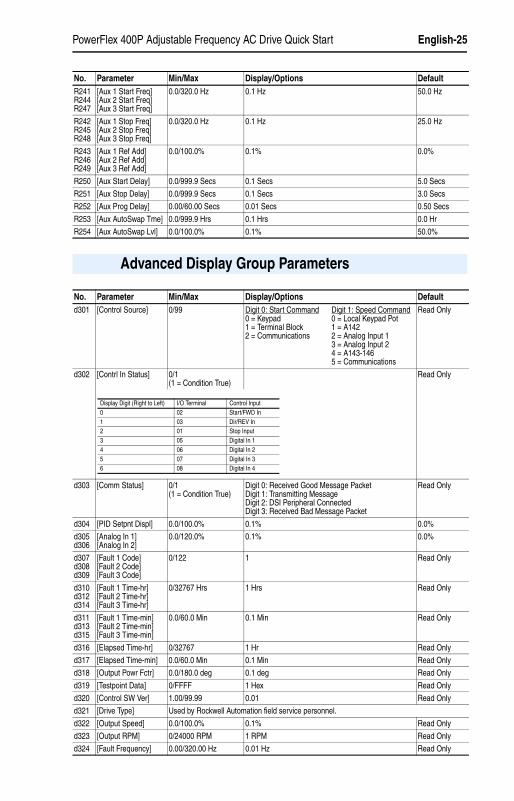
R241R244R247
[Aux 1 Start Freq][Aux 2 Start Freq][Aux 3 Start Freq]
0.0/320.0 Hz 0.1 Hz 50.0 Hz
R242R245R248
[Aux 1 Stop Freq][Aux 2 Stop Freq][Aux 3 Stop Freq]
0.0/320.0 Hz 0.1 Hz 25.0 Hz
R243R246R249
[Aux 1 Ref Add][Aux 2 Ref Add][Aux 3 Ref Add]
0.0/100.0% 0.1% 0.0%
R250 [Aux Start Delay] 0.0/999.9 Secs 0.1 Secs 5.0 Secs
R251 [Aux Stop Delay] 0.0/999.9 Secs 0.1 Secs 3.0 Secs
R252 [Aux Prog Delay] 0.00/60.00 Secs 0.01 Secs 0.50 Secs
R253 [Aux AutoSwap Tme] 0.0/999.9 Hrs 0.1 Hrs 0.0 Hr
R254 [Aux AutoSwap Lvl] 0.0/100.0% 0.1% 50.0%
No. Parameter Min/Max Display/Options Default
Advanced Display Group Parameters
No. Parameter Min/Max Display/Options Defaultd301 [Control Source] 0/99 Digit 0: Start Command
0 = Keypad1 = Terminal Block2 = Communications
Digit 1: Speed Command0 = Local Keypad Pot1 = A1422 = Analog Input 13 = Analog Input 24 = A143-1465 = Communications
Read Only
d302 [Contrl In Status] 0/1(1 = Condition True)
Read Only
d303 [Comm Status] 0/1(1 = Condition True)
Digit 0: Received Good Message PacketDigit 1: Transmitting MessageDigit 2: DSI Peripheral ConnectedDigit 3: Received Bad Message Packet
Read Only
d304 [PID Setpnt Displ] 0.0/100.0% 0.1% 0.0%
d305d306
[Analog In 1][Analog In 2]
0.0/120.0% 0.1% 0.0%
d307d308d309
[Fault 1 Code][Fault 2 Code][Fault 3 Code]
0/122 1 Read Only
d310d312d314
[Fault 1 Time-hr][Fault 2 Time-hr][Fault 3 Time-hr]
0/32767 Hrs 1 Hrs Read Only
d311d313d315
[Fault 1 Time-min][Fault 2 Time-min][Fault 3 Time-min]
0.0/60.0 Min 0.1 Min Read Only
d316 [Elapsed Time-hr] 0/32767 1 Hr Read Only
d317 [Elapsed Time-min] 0.0/60.0 Min 0.1 Min Read Only
d318 [Output Powr Fctr] 0.0/180.0 deg 0.1 deg Read Only
d319 [Testpoint Data] 0/FFFF 1 Hex Read Only
d320 [Control SW Ver] 1.00/99.99 0.01 Read Only
d321 [Drive Type] Used by Rockwell Automation field service personnel.
d322 [Output Speed] 0.0/100.0% 0.1% Read Only
d323 [Output RPM] 0/24000 RPM 1 RPM Read Only
d324 [Fault Frequency] 0.00/320.00 Hz 0.01 Hz Read Only
Display Digit (Right to Left) I/O Terminal Control Input0 02 Start/FWD In1 03 Dir/REV In2 01 Stop Input3 05 Digital In 14 06 Digital In 25 07 Digital In 36 08 Digital In 4
English-26 PowerFlex 400P Adjustable Frequency AC Drive Quick Start
22P-QS001C-EN-P.fm Page 26 Thursday, March 30, 2017 5:55 PM
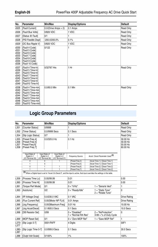
d325 [Fault Current] 0.0/(Drive Amps × 2) 0.1 Amps Read Only
d326 [Fault Bus Volts] 0/820 VDC 1 VDC Read Only
d327 [Status @ Fault] 0/1 1 Read Only
d328 [PID Feedbk Displ] -200.0/200.0% 0.1% Read Only
d329 [DC Bus Ripple V] 0/820 VDC 1 VDC Read Only
d330d331d332d333d334d335d336
[Fault 4 Code][Fault 5 Code][Fault 6 Code][Fault 7 Code][Fault 8 Code][Fault 9 Code][Fault 10 Code]
0/122 1 Read Only
d337d339d341d343d345d347d349
[Fault 4 Time-hr][Fault 5 Time-hr][Fault 6 Time-hr][Fault 7 Time-hr][Fault 8 Time-hr][Fault 9 Time-hr][Fault10 Time-hr]
0/32767 Hrs 1 Hr Read Only
d338d340d342d344d346d348d350
[Fault 4 Time-min][Fault 5 Time-min][Fault 6 Time-min][Fault 7 Time-min][Fault 8 Time-min][Fault 9 Time-min][Fault10 Time-min]
0.0/60.0 Min 0.1 Min Read Only
No. Parameter Min/Max Display/Options Default
Logic Group Parameters
No. Parameter Min/Max Display/Options DefaultL351 [Counter Status] 0/9999 1 Read Only
L352 [Timer Status] 0.0/9999 Secs 0.1 Secs Read Only
L354 [Stp Logic Status] 0/7 1 Read Only
L355L356L357L358
[Preset Freq 4][Preset Freq 5]Preset Freq 6][Preset Freq 7]
0.0/320.0 Hz 0.1 Hz 30.00 Hz40.00 Hz50.00 Hz60.00 Hz
L359 [Process Time Lo] 0.00/99.99 0.01 0.00
L360 [Process Time Hi] 0.00/99.99 0.01 0.00
L361 [Torque Perf Mode] 0/1 0 = “V/Hz” 1 = “Sensrls Vect” 1
L363 [Autotune] 0/2 0 = “Ready/Idle” 1 = “Static Tune”2 = “Rotate Tune”
0
L364 [IR Voltage Drop] 0.0/230.0 VAC 0.1 VAC Drive Rating
L365 [Flux Current Ref] 0.00/[Motor NP FLA] 0.01 Amps Drive Rating
L366 [Jog Frequency] 0.00/[Maximum Freq] 0.01 Hz 10.00 Hz
L367 [Jog Accel/Decel] 0.1/600.0 Secs 0.1 Secs 10.0 Secs
L368 [DB Resistor Sel] 0/99 0 = “Disabled”1 = “Normal RA Res”
2 = “NoProtection”3-99 = % of Duty Cycle
0
L369 [MOP Reset Sel] 0/1 0 = “Zero MOP Ref” 1 = “Save MOP Ref” 1
L370-L377
[Stp Logic 0-7] 0001/FAFF 4 Digits 00F1
L380-L387
[Stp Logic Time 0-7] 0.0/999.9 Secs 0.1 Secs 30.0 Secs
L388 [Outpt Volt Scale] 0/100% 1% 100%
Input State of Digital In 1
(I/O Terminal 05)
Input State of Digital In 2
(I/O Terminal 06)
Input State of Digital In 2
(I/O Terminal 07)Frequency Source Accel / Decel Parameter Used (2)
0 0 1 [Preset Freq 4] [Accel Time 1] / [Decel Time 1]1 0 [Preset Freq 5] [Accel Time 1] / [Decel Time 1]0 1 1 [Preset Freq 6] [Accel Time 2] / [Decel Time 2]1 1 1 [Preset Freq 7] [Accel Time 2] / [Decel Time 2]
(2) When a Digital Input is set to “Accel 2 & Decel 2”, and the input is active, that input overrides the settings in this table.
PowerFlex 400P Adjustable Frequency AC Drive Quick Start English-27
22P-QS001C-EN-P.fm Page 27 Thursday, March 30, 2017 5:55 PM
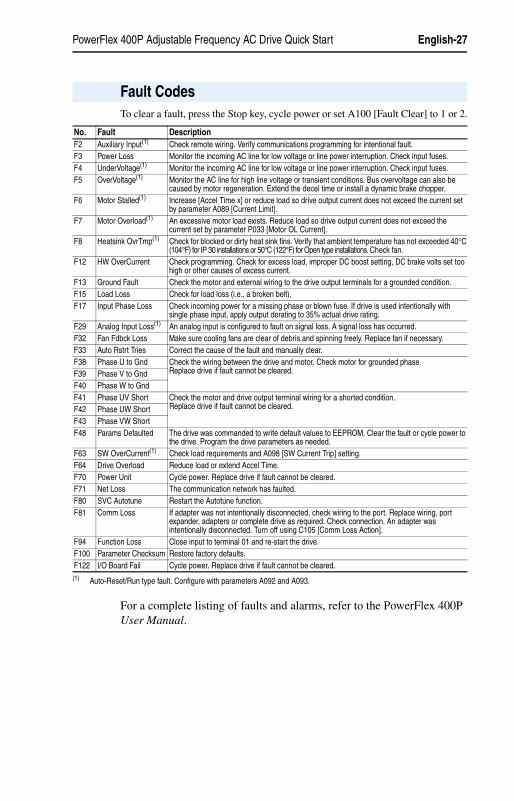
To clear a fault, press the Stop key, cycle power or set A100 [Fault Clear] to 1 or 2.
For a complete listing of faults and alarms, refer to the PowerFlex 400P User Manual.
Fault Codes
No. Fault DescriptionF2 Auxiliary Input(1) Check remote wiring. Verify communications programming for intentional fault.F3 Power Loss Monitor the incoming AC line for low voltage or line power interruption. Check input fuses.F4 UnderVoltage(1) Monitor the incoming AC line for low voltage or line power interruption. Check input fuses.F5 OverVoltage(1) Monitor the AC line for high line voltage or transient conditions. Bus overvoltage can also be
caused by motor regeneration. Extend the decel time or install a dynamic brake chopper.F6 Motor Stalled(1) Increase [Accel Time x] or reduce load so drive output current does not exceed the current set
by parameter A089 [Current Limit].F7 Motor Overload(1) An excessive motor load exists. Reduce load so drive output current does not exceed the
current set by parameter P033 [Motor OL Current].F8 Heatsink OvrTmp(1) Check for blocked or dirty heat sink fins. Verify that ambient temperature has not exceeded 40°C
(104°F) for IP 30 installations or 50°C (122°F) for Open type installations. Check fan.F12 HW OverCurrent Check programming. Check for excess load, improper DC boost setting, DC brake volts set too
high or other causes of excess current.F13 Ground Fault Check the motor and external wiring to the drive output terminals for a grounded condition.F15 Load Loss Check for load loss (i.e., a broken belt).F17 Input Phase Loss Check incoming power for a missing phase or blown fuse. If drive is used intentionally with
single phase input, apply output derating to 35% actual drive rating.F29 Analog Input Loss(1) An analog input is configured to fault on signal loss. A signal loss has occurred.F32 Fan Fdbck Loss Make sure cooling fans are clear of debris and spinning freely. Replace fan if necessary.F33 Auto Rstrt Tries Correct the cause of the fault and manually clear.F38 Phase U to Gnd Check the wiring between the drive and motor. Check motor for grounded phase.
Replace drive if fault cannot be cleared.F39 Phase V to GndF40 Phase W to GndF41 Phase UV Short Check the motor and drive output terminal wiring for a shorted condition.
Replace drive if fault cannot be cleared.F42 Phase UW ShortF43 Phase VW ShortF48 Params Defaulted The drive was commanded to write default values to EEPROM. Clear the fault or cycle power to
the drive. Program the drive parameters as needed.F63 SW OverCurrent(1) Check load requirements and A098 [SW Current Trip] setting.F64 Drive Overload Reduce load or extend Accel Time.F70 Power Unit Cycle power. Replace drive if fault cannot be cleared.F71 Net Loss The communication network has faulted.F80 SVC Autotune Restart the Autotune function.F81 Comm Loss If adapter was not intentionally disconnected, check wiring to the port. Replace wiring, port
expander, adapters or complete drive as required. Check connection. An adapter was intentionally disconnected. Turn off using C105 [Comm Loss Action].
F94 Function Loss Close input to terminal 01 and re-start the drive.F100 Parameter Checksum Restore factory defaults.F122 I/O Board Fail Cycle power. Replace drive if fault cannot be cleared.(1) Auto-Reset/Run type fault. Configure with parameters A092 and A093.

English-28 PowerFlex 400P Adjustable Frequency AC Drive Quick Start
22P-QS001C-EN-P.fm Page 28 Thursday, March 30, 2017 5:55 PM
PowerFlex 400P Frames
Figure 5: PowerFlex 400P Frames C-F IP20/66
Dimensions are in millimeters and (inches).
Dimensions
Output Power Frame SizekW HP 400-480V AC Input2.2-7.5 3-10 C11-15 15-20 C18.5-22 25-30 D30-37 40-50 E45-75 60-100 E90-110 125-150 F132-160 200-250 G200-250 300-350 H
a
eb
d
f
c
Frame a b c d e fWeight (1) kg (lbs.)
C 130.0 (5.1) 260.0 (10.2) 180.0 (7.1) 116.0 (4.57) 246.0 (9.7) 5.8 (0.23) 4.33 (9.5)D 250.0 (9.84) 436.2 (17.17) 206.1 (8.11) 226.0 (8.90) 383.4 (15.09) 9.0 (0.35) 14.0 (30.9)E 370.0 (14.57) 605.5 (23.84) 259.2 (10.21) 335.0 (13.19) 567.4 (22.34) 8.5 (0.33) 51.2 (112.9)F 425.0 (16.73) 850.0 (33.46) 264.0 (10.39) 381.0 (15.00) 647.5 (25.49) 13.0 (0.51) 88.0 (194.0)G 425.0 (16.73) 892.0 (35.12) 264.0 (10.39) 381.0 (15.00) 819.5 (32.26) 13.0 (0.51) 106 (233.7)H 529.0 (20.83) 1363.8 (53.60) 358.6 (14.12) 480.0 (18.90) 1119.0 (44.06) 13.0 (0.51) 177 (390.2)
(1) Weights include HIM and Standard I/O.

PowerFlex 400P Adjustable Frequency AC Drive Quick Start English-29
22P-QS001C-EN-P.fm Page 29 Thursday, March 30, 2017 5:55 PM
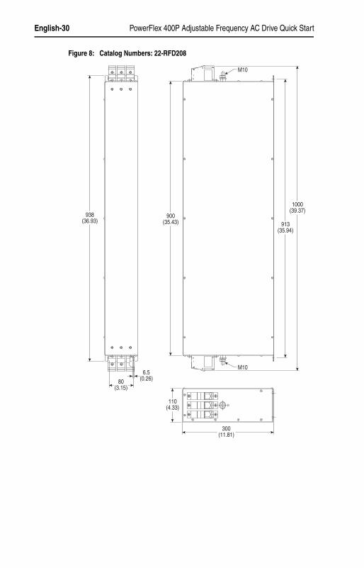
EMC Line Filters
Dimensions are in millimeters and (inches).
Figure 6: Catalog Numbers: 22-RF018-CS, 22-RF018-CL, 22-RF026-CS, 22-RF026-CL, 22-RF026-CL, 22-RF034-CS
Figure 7: Catalog Numbers: 22-RFD036, 22-RFD050, 22-RFD070, 22-RFD100, 22-RFD150, 22-RFD180
130(5.12)90
(3.54)
60(2.36)32
(1.26)
17(0.67) 30
(1.18)5.5 (0.22)
297(11.69) 297
(11.69)
309(12.17) B
E
AD C
F
G
Catalog Number A B C D E F G
22-RFD036 74 (2.91) 272 (10.71) 161 (6.34) 60 (2.36) 258 (10.16) 7.5 (0.30) 7 (0.28)
22-RFD050 93 (3.66) 312 (12.28) 190 (7.48) 79 (3.11) 298 (11.73) 13.5 (0.53) 7 (0.28)
22-RFD070 93 (3.66) 312 (12.28) 190 (7.48) 79 (3.11) 298 (11.73) 13.5 (0.53) 7 (0.28)
22-RFD100 93 (3.66) 312 (12.28) 190 (7.48) 79 (3.11) 298 (11.73) 13.5 (0.53) 7 (0.28)
22-RFD150 126 (4.96) 312 (12.28) 224 (8.82) 112 (4.41) 298 (11.73) 19.5 (0.77) 7 (0.28)
22-RFD180 126 (4.96) 312 (12.28) 224 (8.82) 112 (4.41) 298 (11.73) 27 (1.06) 7 (0.28)
English-30 PowerFlex 400P Adjustable Frequency AC Drive Quick Start
22P-QS001C-EN-P.fm Page 30 Thursday, March 30, 2017 5:55 PM
Figure 8: Catalog Numbers: 22-RFD208
938(36.93)
900(35.43) 913
(35.94)
1000(39.37)
110(4.33)
300(11.81)
80(3.15)
6.5(0.26)
M10
M10

PowerFlex 400P Adjustable Frequency AC Drive Quick Start English-31
22P-QS001C-EN-P.fm Page 31 Thursday, March 30, 2017 5:55 PM
Figure 9: Catalog Numbers: 22-RFD323 and 22-RFD480
Catalog Number A B C D E F G
22-RFD323 300 (11.81) 735 (28.94) 145 (5.71) 275 (10.83) 689 (27.13) 64 (2.52) 180 (7.09)
22-RFD480 300 (11.81) 882 (34.72) 145 (5.71) 275 (10.83) 836 (32.91) 64 (2.52) 240 (9.45)
aa
aaM11
Ø 10.8(0.43)
45°
A
D
C
F
250(11.81)
25(0.98)
60(2.36)
60(2.36)
10(0.39)
50(1.97)
12.5(0.49)
6(0.24)
G
G
G
EB
M12
ø 9(0.35)
x 8
3(0.12)
64(2.52)
18(0.71)
English-32 PowerFlex 400P Adjustable Frequency AC Drive Quick Start
22P-QS001C-EN-P.fm Page 32 Thursday, March 30, 2017 5:55 PM
www.rockwellautomation.com
Americas: Rockwell Automation, 1201 South Second Street, Milwaukee, WI 53204-2496 USA, Tel: (1) 414.382.2000, Fax: (1) 414.382.4444
Europe/Middle East/Africa: Rockwell Automation NV, Pegasus Park, De Kleetlaan 12a, 1831 Diegem, Belgium, Tel: (32) 2 663 0600, Fax: (32) 2 663 0640
Asia Pacific: Rockwell Automation, Level 14, Core F, Cyberport 3, 100 Cyberport Road, Hong Kong, Tel: (852) 2887 4788, Fax: (852) 2508 1846
Power, Control and Information Solutions Headquarters
Publication 22P-QS001C-EN-P – January 2017Supersedes Publication 22P-QS001B-EN-P – March 2010 Copyright © 2017 Rockwell Automation, Inc. All rights reserved. Printed in China.