friction and wear performance analysis of hydrofluoroether
TRANSCRIPT
Friction and wear performance analysis of hydrofluoroether-7000
refrigerant as lubricant
Muhammad Usman Bhutta a,b
, Zulfiqar Ahmad Khan*a
a NanoCorr, Energy & Modelling (NCEM) Research Group, Department of Design & Engineering,
Bournemouth University, Talbot Campus, Fern Barrow, Poole, BH12 5BB b School of Mechanical & Manufacturing Engineering (SMME), National University of Sciences & Technology
(NUST), Campus H-12, Islamabad, Pakistan *Corresponding author: [email protected]
Abstract
The disquiet about global warming has triggered the formulation and introduction of new generation
of refrigerants. Hydrofluoroethers (HFEs) are within the family of newly developed environmentally
friendly refrigerants with a wide range of application areas. Hydrofluoroethers reportedly have better
heat transfer and thermodynamic properties. In addition to an understanding and knowledge of the
thermodynamic properties of refrigerants, it is essential to understand the tribological properties of
refrigerants within the context of sustainable development. Tribo-performance of refrigerants applied
in refrigeration, air-conditioning and energy systems directly influences the durability, reliability and
cost effectiveness of the system. HFE-7000 has considerable potential for engineering applications in
green energy and low carbon technologies. In this research, a detailed investigation has been
performed to assess friction and wear performance of HFE-7000 (HFE-347mcc3). HFE-7000 has
been employed as lubricants. Experimental results indicate the formation of tribo-films on the topmost
surfaces. Energy-Dispersive X-ray Spectroscopic (EDS) and X-ray Photoelectron Spectroscopic
(XPS) analyses on the tested samples revealed significant presence of oxygenated and fluorinated
anti-wear tribo-films. These oxygen and fluorine containing tribo-layers prevent metal to metal
contact and contribute to the reduction of friction and wear.
Keywords: Environment-friendly refrigerants, tribo-films, sliding contact, low carbon technology,
EDS, XPS.
1. Introduction
Anthropogenic global climate change, rise in worldwide economic development and the increase in
global population has substantially increased the use of air-conditioning and refrigeration systems
worldwide. Previous generation of artificially formulated refrigerants have high environmental
implications and these refrigerants contribute towards global warming and ozone depletion [1, 2].
Although the ozone depleting refrigerants have almost been phased out, the artificially formulated
refrigerants which are one of the main contributors towards global warming are still largely in use [3].
The types of refrigerants employed in cooling, refrigeration and air-conditioning systems have
evolved over the years.
Naturally occurring compounds which have good heat transfer and thermodynamic properties such as
Ammonia, Hydrocarbons, Sulfur Dioxide, Methyl Formate and Methyl Chloride were being used in
refrigeration systems before 1930s. Almost all of these compounds are toxic, flammable or both. As a
result of their use accidents were common [4]. Sulfur Dioxide, Methyl Formate and Methyl Chloride
were being commonly used in domestic refrigerators which are highly toxic and highly flammable.
Several fatal accidents occurred due to methyl chloride leakage from refrigerators in 1920s [3]. This
led to a collaborative research in 1928 to find alternative replacement refrigerants that would be
nontoxic and non-flammable which resulted in the development of Chlorofluorocarbons and
Hydrochlorofluorocarbons.
Chlorofluorocarbons (CFCs) and Hydrochlorofluorocarbons (HCFCs) were extensively used as
refrigerants till the mid-1990s. CFCs are chemicals containing atoms of chlorine, carbon and fluorine.
HCFCs have an additional hydrogen atom and their molecular structure resembles closely to CFCs.
CFCs and HCFCs are non-toxic and non-flammable refrigerants possessing excellent thermodynamic
properties. This led to the extensive use of CFCs and HCFCs in various applications including uses in
residential refrigerators, domestic air-conditioning systems, commercial applications, small scale
industrial and in automotive air-conditioning units. Besides having excellent thermodynamic
qualities, CFCs and HCFCs also possess exceptional tribological properties [5-14]. CFCs and HCFCs
were reported to form protective surface films under normal compressor operating conditions which
enhanced the friction and wear of interacting parts. The discovery of the depletion of the ozone layer
and publication of the destructive effects of CFCs on the stratospheric ozone layer in 1974 [15] led to
the realisation that CFCs have an extremely high ozone depletion potential and are leading to the
destruction of the ozone. Vienna Convention for the Protection of the Ozone layer which was
followed by the Montreal Protocol on Substances that Deplete the Ozone Layer in 1987 put a ban on
CFCs [16]. Montreal Protocol was enforced in 1989 worldwide which banned the use of CFCs by the
start of year 1996 in developed countries. HCFCs have lower ODP (Ozone Depletion Potential)
values as compared to CFCs, which has allowed their use for a longer period of time. HCFCs are
planned to be phased out by the end of year 2020.
Refrigerators and air-conditioners had become common household items, bans and restrictions on
CFCs and HCFCs meant that alternative refrigerants had to be introduced, however this led to the
need for assessing tribo-implications of these refrigerants in turn their implications on the durability.
This paved the way to the development and introduction of Hydrofluorocarbons (HFCs). HFCs are
synthetically produced refrigerants which contains hydrogen atoms, fluorine and carbon with zero
ODP. HFCs had thermodynamic properties matching CFCs [17-21], which resulted in their extensive
use as substitute refrigerants. CFCs and HCFCs were compatible with mineral oils, HFCs however
were incompatible and immiscible with mineral oils. This meant that new lubricants with various
additives had to be developed for the use of HFC refrigerants in compressors. After the introduction
and acceptance of HFC refrigerants various researcher around the world started investigating the
tribological performance of these refrigerants. A number of tribological studies including [5, 6, 22-33]
were conducted to evaluate the performance of HFC refrigerants by using a range of lubricants and
additives. Numerous studies [5-11, 13, 14, 23, 34-40] were also conducted which compared the
friction, wear and lubricity performance of HFCs to HCFCs and CFCs. Most of the investigations that
directly compared the tribological properties of HFCs to HCFCs and CFCs concluded that CFCs and
HCFCs have superior tribological performance as compared to HFCs. Fluorine in HFCs did not
decompose under normal compressor operating conditions and did not form protective surface films.
Having zero ODP, HFCs were deployed worldwide and their harmful global warming implications
were not considered at the time of their commercialisation, however high global warming
implications of HFCs were realised later. The Kyoto Protocol in 1997 to the United Nations
Framework Convention of Climate Change placed limits on CO2 and other greenhouse gases. HFCs
were identified to be amongst the main contributors to global warming [41] and they will be banned in
any hermetically sealed system from the year 2022.
As a response to Environmental Impact Legislations naturally occurring hydrocarbons became of
interest after Kyoto Protocol. Amongst hydrocarbons, HC-600a gained particular attention as it can
replace HFC-134a. Various different investigations were conducted to examine the tribological
performance of HC-R600a under different testing conditions [42-49]. The study [42] showed that
environmental burden is greater by using HFC-134a based systems in comparison to systems based on
HC-600a. Hydrocarbon refrigerants are also considered to be up to 50% more efficient thermal
conductors than fluorocarbon refrigerants [3]. However due to the inherited high flammability
concerns associated with hydrocarbons their applications are limited and thus new refrigerants have to
be introduced.
This has now forced the introduction of new artificially formulated alternative refrigerants. The
refrigerant industry has introduced new refrigerants namely Hydrofluoroolefins (HFOs) and
Hydrofluoroethers (HFEs). HFOs and HFEs have zero ODP and lower global warming potential
(GWP). HFO-1234yf has thermodynamic properties matching HFC-134a and is considered a direct
replacement of HFC-134a [50]. This means that HFO-1234yf can be easily introduced into HFC-134a
based refrigeration cycles. Tribological evaluation of HFOs is underway and various studies [51-57]
have shown that HFOs possess very good tribological properties because the fluorine in HFOs
chemically reacts with the lubricants and the interacting metals to form protective tribological films
on the surface. Some of these studies have also compared HFO-1234yf directly with HFC-134a under
identical operating conditions and have concluded that HFO-1234yf has superior tribological
properties compared to HFC-134a [51-54]. HFOs however are mildly flammable and their
flammability restricts their application areas and places of use.
In recent years focus has also shifted towards refrigerants that are naturally occurring such as
hydrocarbons and carbon dioxide, however the high flammability of hydrocarbons restricts their
application range. CO2 based refrigeration systems require extremely high pressures to operate which
results in higher design, material and operation costs.
HFEs are non-flammable refrigerants having low GWP and zero ODP. HFEs are odourless,
colourless, low toxic, low viscous refrigerants which are normally liquid at room temperature and
look identical to water. HFEs have a number of applications for example they can be used in cascaded
refrigeration systems, in freeze drying units, in fuels cells, in chemical reactors, in high voltage
transformers, as cleaning and rinsing agents, as lubricant carriers, in vapour degreasing applications
and in renewable solar thermal systems [58]. Various studies like [59, 60] have demonstrated that
hydrofluoroethers possess good thermodynamics properties especially in low carbon technology and
energy applications [61]. HFEs are also potential replacements of HFCs, HCFCs and PFCs [62].
There is however very limited work that has been reported on the tribological performance of newly
developed HFEs. The only reported works are [63, 64]. The study [63] examined the properties of
polyester in HFE-245mc atmosphere which was published back in 2002 while only the wear
performance analysis of HFE-347mcc3 was performed with no comment on friction in [64].
At the time of writing this paper, no work has been published that looks into the wear as well as
friction performance of 1-methoxyheptafluoropropane (HFE-7000). The study of tribo performance of
this refrigerant is the novelty in this research. This is a promising new refrigerant with significant
potential for industrial applications including low carbon technologies, clean energy, automotive and
aerospace industries.
This study has been undertaken to experimentally evaluate the friction, wear and lubricity
performance of HFE-7000 in a modified micro-friction machine. The chamber pressure and
temperature were continuously monitored and controlled to keep the refrigerant in liquid state during
the testing to sustain saturated contacts. The tribological effects of load, temperature and surface
roughness were studied by using Hydrofluororther-7000 as lubrication medium without using any
external lubricant. A number of studies have been performed and reported in the past to investigate
the tribological performance of numerous refrigerants without using any lubricants [11, 39, 43, 45, 47,
48, 53, 65-70]. Un-lubricated conditions are used to better understand the lubricity of the refrigerants
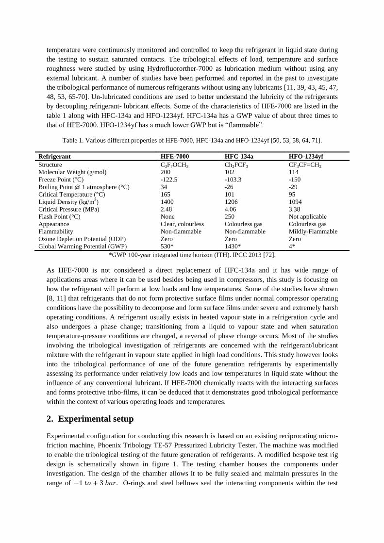
by decoupling refrigerant- lubricant effects. Some of the characteristics of HFE-7000 are listed in the
table 1 along with HFC-134a and HFO-1234yf. HFC-134a has a GWP value of about three times to
that of HFE-7000. HFO-1234yf has a much lower GWP but is “flammable”.
Table 1. Various different properties of HFE-7000, HFC-134a and HFO-1234yf [50, 53, 58, 64, 71].
Refrigerant HFE-7000 HFC-134a HFO-1234yf
Structure C3F7OCH3 Ch2FCF3 CF3CF=CH2
Molecular Weight (g/mol) 200 102 114
Freeze Point (°C) -122.5 -103.3 -150
Boiling Point @ 1 atmosphere (°C) 34 -26 -29
Critical Temperature (°C) 165 101 95
Liquid Density (kg/m3) 1400 1206 1094
Critical Pressure (MPa) 2.48 4.06 3.38
Flash Point (°C) None 250 Not applicable
Appearance Clear, colourless Colourless gas Colourless gas
Flammability Non-flammable Non-flammable Mildly-Flammable
Ozone Depletion Potential (ODP) Zero Zero Zero
Global Warming Potential (GWP) 530* 1430* 4*
*GWP 100-year integrated time horizon (ITH). IPCC 2013 [72].
As HFE-7000 is not considered a direct replacement of HFC-134a and it has wide range of
applications areas where it can be used besides being used in compressors, this study is focusing on
how the refrigerant will perform at low loads and low temperatures. Some of the studies have shown
[8, 11] that refrigerants that do not form protective surface films under normal compressor operating
conditions have the possibility to decompose and form surface films under severe and extremely harsh
operating conditions. A refrigerant usually exists in heated vapour state in a refrigeration cycle and
also undergoes a phase change; transitioning from a liquid to vapour state and when saturation
temperature-pressure conditions are changed, a reversal of phase change occurs. Most of the studies
involving the tribological investigation of refrigerants are concerned with the refrigerant/lubricant
mixture with the refrigerant in vapour state applied in high load conditions. This study however looks
into the tribological performance of one of the future generation refrigerants by experimentally
assessing its performance under relatively low loads and low temperatures in liquid state without the
influence of any conventional lubricant. If HFE-7000 chemically reacts with the interacting surfaces
and forms protective tribo-films, it can be deduced that it demonstrates good tribological performance
within the context of various operating loads and temperatures.
2. Experimental setup
Experimental configuration for conducting this research is based on an existing reciprocating micro-
friction machine, Phoenix Tribology TE-57 Pressurized Lubricity Tester. The machine was modified
to enable the tribological testing of the future generation of refrigerants. A modified bespoke test rig
design is schematically shown in figure 1. The testing chamber houses the components under
investigation. The design of the chamber allows it to be fully sealed and maintain pressures in the
range of O-rings and steel bellows seal the interacting components within the test
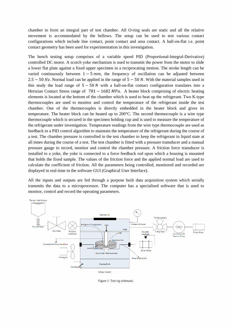
chamber to form an integral part of test chamber. All O-ring seals are static and all the relative
movement is accommodated by the bellows. The setup can be used to test various contact
configurations which include line contact, point contact and area contact. A ball-on-flat i.e. point
contact geometry has been used for experimentation in this investigation.
The bench testing setup comprises of a variable speed PID (Proportional-Integral-Derivative)
controlled DC motor. A scotch yoke mechanism is used to transmit the power from the motor to slide
a lower flat plate against a fixed upper specimen in a reciprocating motion. The stroke length can be
varied continuously between , the frequency of oscillation can be adjusted between
. Normal load can be applied in the range of . With the material samples used in
this study the load range of with a ball-on-flat contact configuration translates into a
Hertzian Contact Stress range of . A heater block comprising of electric heating
elements is located at the bottom of the chamber which is used to heat up the refrigerant. Two K-type
thermocouples are used to monitor and control the temperature of the refrigerant inside the test
chamber. One of the thermocouples is directly embedded in the heater block and gives its
temperature. The heater block can be heated up to 200°C. The second thermocouple is a wire type
thermocouple which is secured in the specimen holding cup and is used to measure the temperature of
the refrigerant under investigation. Temperature readings from the wire type thermocouple are used as
feedback in a PID control algorithm to maintain the temperature of the refrigerant during the course of
a test. The chamber pressure is controlled in the test chamber to keep the refrigerant in liquid state at
all times during the course of a test. The test chamber is fitted with a pressure transducer and a manual
pressure gauge to record, monitor and control the chamber pressure. A friction force transducer is
installed to a yoke, the yoke is connected to a force feedback rod upon which a housing is mounted
that holds the fixed sample. The values of the friction force and the applied normal load are used to
calculate the coefficient of friction. All the parameters being controlled, monitored and recorded are
displayed in real-time in the software GUI (Graphical User Interface).
All the inputs and outputs are fed through a purpose built data acquisition system which serially
transmits the data to a microprocessor. The computer has a specialised software that is used to
monitor, control and record the operating parameters.
Figure 1: Test rig schematic.
3. Testing Procedure
The steel flat circular specimen is placed in the cup which is then secured on the oscillating rod with
the help of screws. Then the wire type thermocouple is fastened into position. Steel ball is fixed on the
ball-holder with the help of grub screws and ball holder is connected to the ball holder shaft. The shaft
provides a means to secure the ball-holder in position and also functions as a means to apply the
vertical normal load. After this the chamber is closed and sealed. The chamber is then vacuumed so as
to minimise the effects of oxygen and ambient air during testing.
After the chamber has been vacuumed, HFE-7000 is introduced in the system by using the shut-off
and flow valves. Sufficient amount of refrigerant is charged so that the cup overflows and the bottom
flat specimen is fully immersed in the fluid which ensures fully lubricated conditions at all times. The
extra overflown refrigerant gets collected at the bottom of the chamber where the heating block is
located. This overflown refrigerant assists heat transfer from the heater block and helps maintain the
refrigerant temperature in the specimen cup. The vacuum inside the test chamber and gravitational
force helps the refrigerant to flow from the cylinder into the cup. The chamber lid has a transparent
glass top which allows the operator to physically observe chamber conditions at all times. Next the
desired load is manually applied. After this the control algorithm is run and the refrigerant inside the
cup in the testing chamber is heated to the required temperature. The refrigerant temperature is
controlled by using values from the wire type thermocouple and feedback PID control. Once the
temperature reaches its specific value, the temperature of the refrigerant is stabilised and maintained
for one hour before starting a test. After the temperature has been stabilised and has been maintained
to the desired value for one hour, a test is run for two hours.
The oscillating frequency is controlled by using feedback controlled driver motor. The motor, the
heater and all the transducers are connected to a microprocessor based central data acquisition and
control system. The values of the friction force, the chamber pressure values, the temperature readings
from the heater block, temperature of the refrigerant and the motor speed are continuously recorded in
a spreadsheet.
Flat circular plate specimens of three different values of average surface roughness,
made of EN1A steel were used. The balls were made of AISI 52100 steel
having an average surface value of . The flat specimens are circular in shape having
thickness of 2.75 mm and 30 mm diameter. The steel balls are 10 mm in diameter. Three different
loads were applied. Three different temperatures were
used in this study. All tests were performed at a constant reciprocating of having a stroke length
of . Each flat disc sample was mechanically grinded and then polished to the desired surface
roughness after which each sample was ultrasonically treated with acetone for five minutes and then
dried with warm air using a specimen drier before each experiment. The grinding and polishing
process followed by the ultrasonic treatment with acetone of the specimens assured the removal of
any unwanted/oxide surface films pre-experimentation. Each experiment lasted two hours and
repeatability was ensured by conducting each experiment at least twice.
4. Results and discussion
4.1. Friction
Results of friction have been discussed in terms of real-time coefficient of friction values, average
coefficient of friction and average frictional force. Kinematic viscosity of HFE-7000 at 20°C is
0.32 cSt, at 30°C is 0.29 cSt and at 40°C is 0.27 cSt [58]. A detailed discussion on results of
friction obtained in this study is provided in sections 4.1.1, 4.1.2 and 4.1.3 respectively.
4.1.1. Coefficient of Friction
Fully lubricated conditions were established since the start of the experiment and were maintained
throughout the test. The results of the variation of the coefficient of friction with changing normal
load, refrigerant temperature and average surface roughness are presented in figures 2, 3 and 4
respectively.
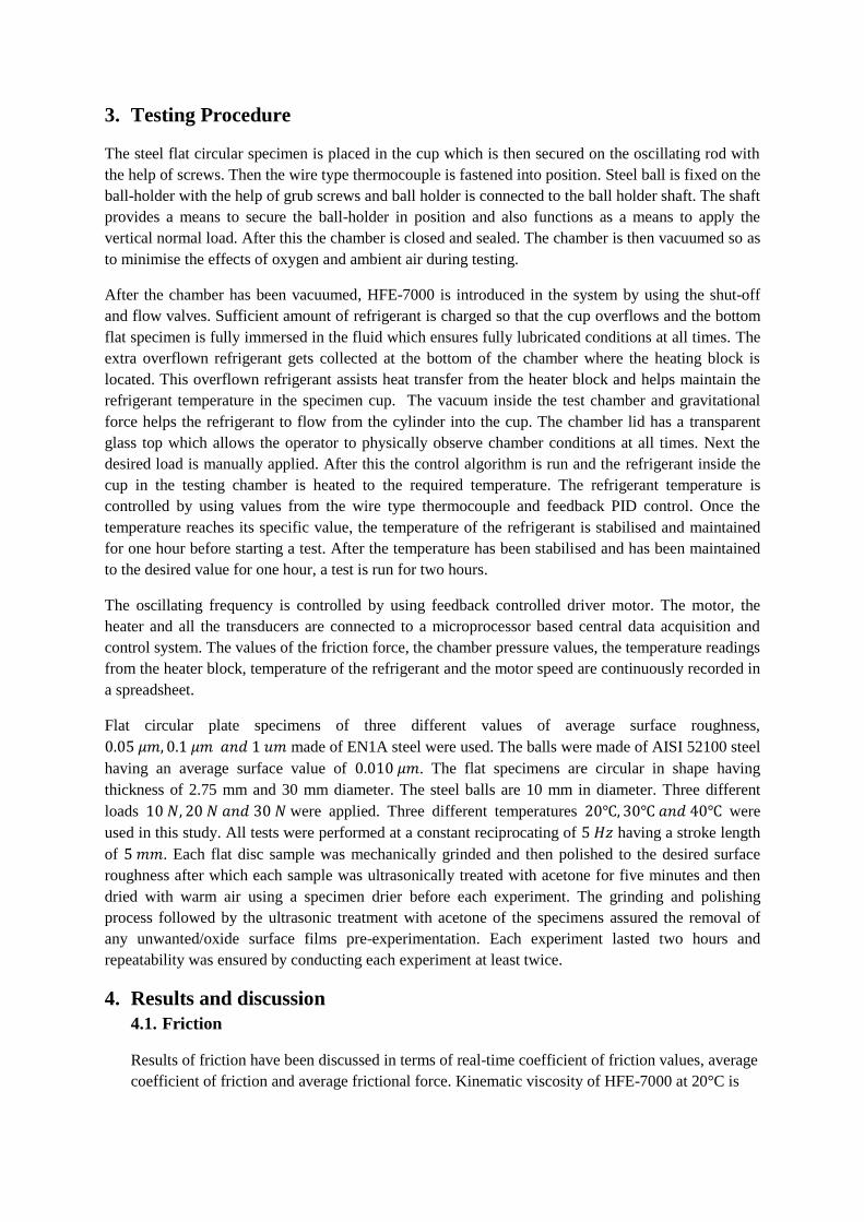
For Ra of the values of the friction coefficient decreased with an increase in load at HEF-
7000 temperature of . An increase in normal load from resulted in fewer overall
variations in the coefficient of friction and more stable values. For normal load of and fluid
temperature of the coefficient of friction increased almost linearly to a maximum value after
which it started to decrease. With some fluctuations, the coefficient of friction decreased after
increasing initially and reached a stable value at the end of the experiment. The decrease in the
coefficient of friction is probably because of the development of protective tribo-films after which the
coefficient of friction decreases and once the tribo-films have been formed on the entire wear track
the friction coefficient reaches a stable value.
(a)
0
0.1
0.2
0.3
0.4
0.5
0.6
0 1000 2000 3000 4000 5000 6000 7000 8000
Fri
ctio
n C
oef
fici
ent,
Time, s
Ra 0.05 m, Temperature 20°C
10 N 20 N 30 N
(b)
(c)
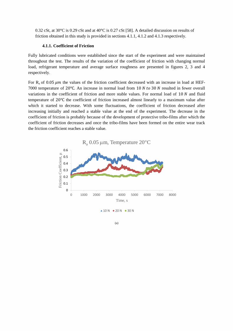
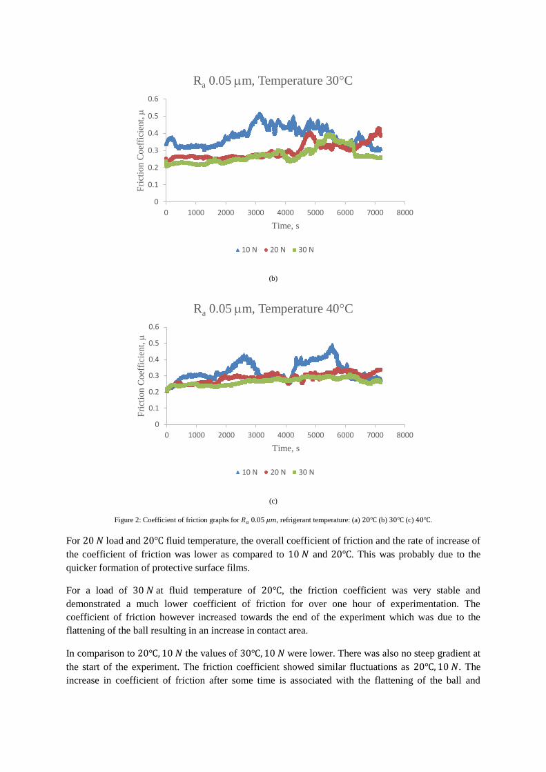
Figure 2: Coefficient of friction graphs for , refrigerant temperature: (a) (b) (c) .
For load and fluid temperature, the overall coefficient of friction and the rate of increase of
the coefficient of friction was lower as compared to and . This was probably due to the
quicker formation of protective surface films.
For a load of at fluid temperature of , the friction coefficient was very stable and
demonstrated a much lower coefficient of friction for over one hour of experimentation. The
coefficient of friction however increased towards the end of the experiment which was due to the
flattening of the ball resulting in an increase in contact area.
In comparison to the values of were lower. There was also no steep gradient at
the start of the experiment. The friction coefficient showed similar fluctuations as . The
increase in coefficient of friction after some time is associated with the flattening of the ball and
0
0.1
0.2
0.3
0.4
0.5
0.6
0 1000 2000 3000 4000 5000 6000 7000 8000
Fri
ctio
n C
oef
fici
ent,
Time, s
Ra 0.05 m, Temperature 30°C
10 N 20 N 30 N
0
0.1
0.2
0.3
0.4
0.5
0.6
0 1000 2000 3000 4000 5000 6000 7000 8000
Fri
ctio
n C
oef
fici
ent,
Time, s
Ra 0.05 m, Temperature 40°C
10 N 20 N 30 N
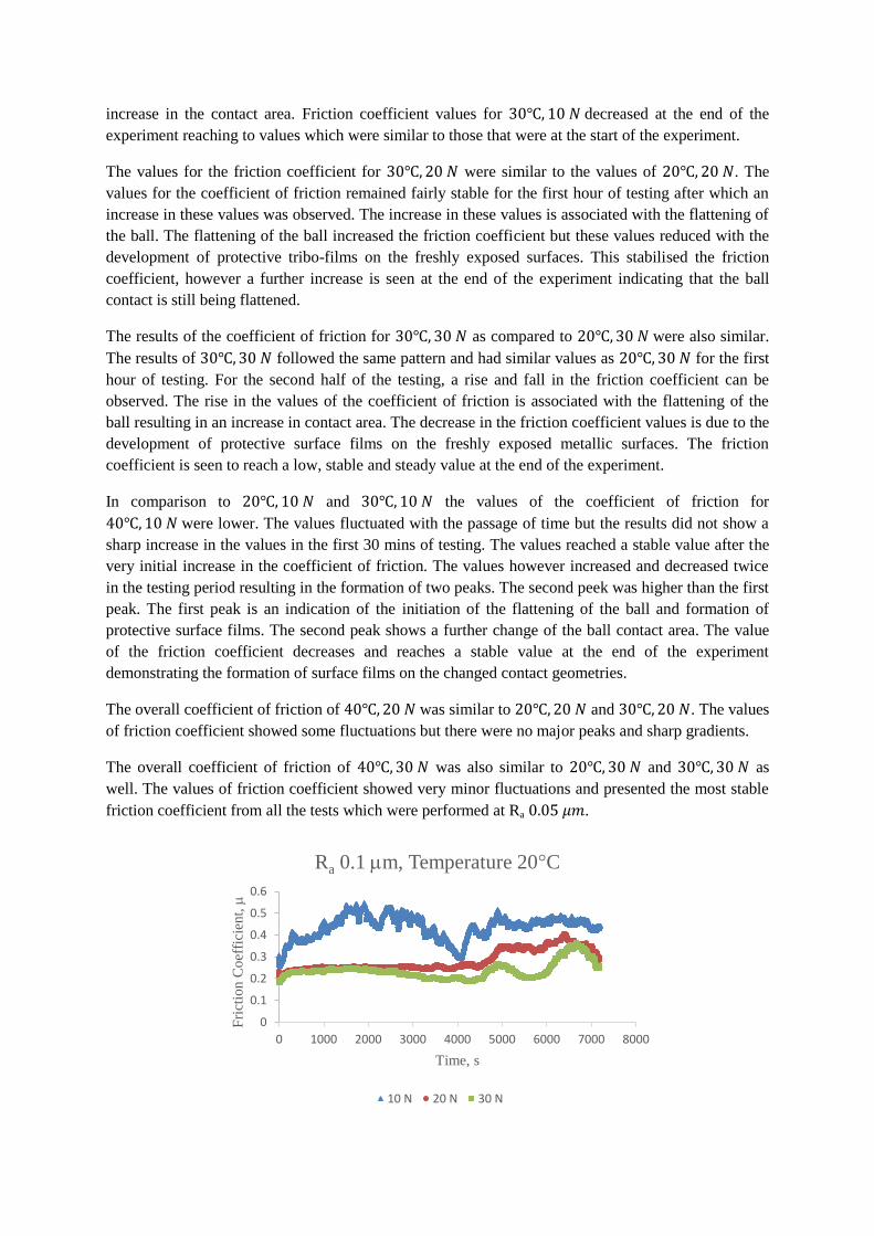
increase in the contact area. Friction coefficient values for decreased at the end of the
experiment reaching to values which were similar to those that were at the start of the experiment.
The values for the friction coefficient for were similar to the values of . The
values for the coefficient of friction remained fairly stable for the first hour of testing after which an
increase in these values was observed. The increase in these values is associated with the flattening of
the ball. The flattening of the ball increased the friction coefficient but these values reduced with the
development of protective tribo-films on the freshly exposed surfaces. This stabilised the friction
coefficient, however a further increase is seen at the end of the experiment indicating that the ball
contact is still being flattened.
The results of the coefficient of friction for as compared to were also similar.
The results of followed the same pattern and had similar values as for the first
hour of testing. For the second half of the testing, a rise and fall in the friction coefficient can be
observed. The rise in the values of the coefficient of friction is associated with the flattening of the
ball resulting in an increase in contact area. The decrease in the friction coefficient values is due to the
development of protective surface films on the freshly exposed metallic surfaces. The friction
coefficient is seen to reach a low, stable and steady value at the end of the experiment.
In comparison to and the values of the coefficient of friction for
were lower. The values fluctuated with the passage of time but the results did not show a
sharp increase in the values in the first 30 mins of testing. The values reached a stable value after the
very initial increase in the coefficient of friction. The values however increased and decreased twice
in the testing period resulting in the formation of two peaks. The second peek was higher than the first
peak. The first peak is an indication of the initiation of the flattening of the ball and formation of
protective surface films. The second peak shows a further change of the ball contact area. The value
of the friction coefficient decreases and reaches a stable value at the end of the experiment
demonstrating the formation of surface films on the changed contact geometries.
The overall coefficient of friction of was similar to and . The values
of friction coefficient showed some fluctuations but there were no major peaks and sharp gradients.
The overall coefficient of friction of was also similar to and as
well. The values of friction coefficient showed very minor fluctuations and presented the most stable
friction coefficient from all the tests which were performed at Ra .
0
0.1
0.2
0.3
0.4
0.5
0.6
0 1000 2000 3000 4000 5000 6000 7000 8000
Fri
ctio
n C
oef
fici
ent,
Time, s
Ra 0.1 m, Temperature 20°C
10 N 20 N 30 N
(a)
(b)
(c)
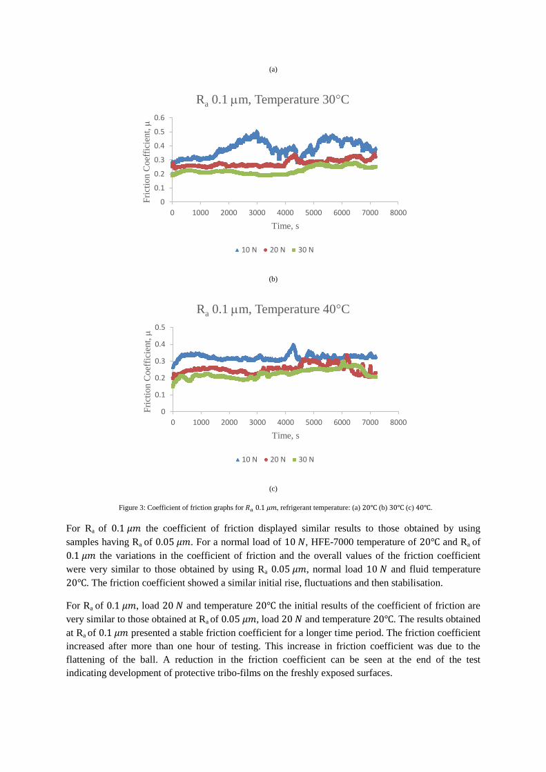
Figure 3: Coefficient of friction graphs for , refrigerant temperature: (a) (b) (c) .
For Ra of the coefficient of friction displayed similar results to those obtained by using
samples having Ra of . For a normal load of , HFE-7000 temperature of and Ra of
the variations in the coefficient of friction and the overall values of the friction coefficient
were very similar to those obtained by using Ra , normal load and fluid temperature
. The friction coefficient showed a similar initial rise, fluctuations and then stabilisation.
For Ra of , load and temperature the initial results of the coefficient of friction are
very similar to those obtained at Ra of , load and temperature . The results obtained
at Ra of presented a stable friction coefficient for a longer time period. The friction coefficient
increased after more than one hour of testing. This increase in friction coefficient was due to the
flattening of the ball. A reduction in the friction coefficient can be seen at the end of the test
indicating development of protective tribo-films on the freshly exposed surfaces.
0
0.1
0.2
0.3
0.4
0.5
0.6
0 1000 2000 3000 4000 5000 6000 7000 8000
Fri
ctio
n C
oef
fici
ent,
Time, s
Ra 0.1 m, Temperature 30°C
10 N 20 N 30 N
0
0.1
0.2
0.3
0.4
0.5
0 1000 2000 3000 4000 5000 6000 7000 8000
Fri
ctio
n C
oef
fici
ent,
Time, s
Ra 0.1 m, Temperature 40°C
10 N 20 N 30 N
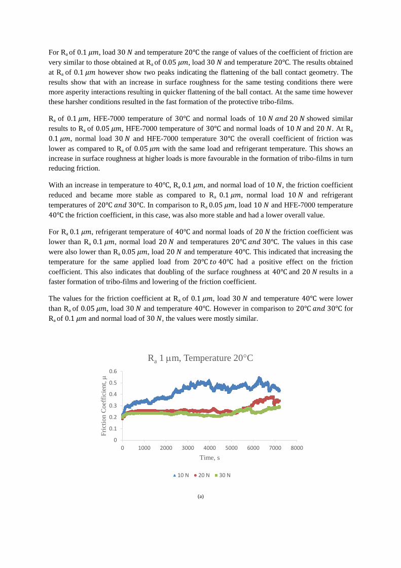
For Ra of , load and temperature the range of values of the coefficient of friction are
very similar to those obtained at Ra of , load and temperature . The results obtained
at Ra of however show two peaks indicating the flattening of the ball contact geometry. The
results show that with an increase in surface roughness for the same testing conditions there were
more asperity interactions resulting in quicker flattening of the ball contact. At the same time however
these harsher conditions resulted in the fast formation of the protective tribo-films.
Ra of , HFE-7000 temperature of and normal loads of showed similar
results to Ra of , HFE-7000 temperature of and normal loads of and . At Ra
, normal load and HFE-7000 temperature the overall coefficient of friction was
lower as compared to Ra of with the same load and refrigerant temperature. This shows an
increase in surface roughness at higher loads is more favourable in the formation of tribo-films in turn
reducing friction.
With an increase in temperature to , Ra , and normal load of , the friction coefficient
reduced and became more stable as compared to Ra , normal load and refrigerant
temperatures of . In comparison to Ra , load and HFE-7000 temperature
the friction coefficient, in this case, was also more stable and had a lower overall value.
For Ra , refrigerant temperature of and normal loads of the friction coefficient was
lower than Ra , normal load and temperatures . The values in this case
were also lower than Ra , load and temperature . This indicated that increasing the
temperature for the same applied load from had a positive effect on the friction
coefficient. This also indicates that doubling of the surface roughness at and results in a
faster formation of tribo-films and lowering of the friction coefficient.
The values for the friction coefficient at Ra of , load and temperature were lower
than Ra of , load and temperature . However in comparison to for
Ra of and normal load of , the values were mostly similar.
(a)
0
0.1
0.2
0.3
0.4
0.5
0.6
0 1000 2000 3000 4000 5000 6000 7000 8000
Fri
ctio
n C
oef
fici
ent,
Time, s
Ra 1 m, Temperature 20°C
10 N 20 N 30 N
(b)
(c)
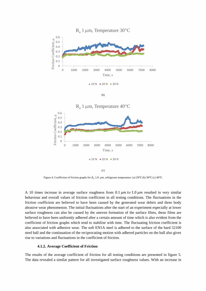
Figure 4: Coefficient of friction graphs for , refrigerant temperature: (a) (b) (c) .
A 10 times increase in average surface roughness from resulted in very similar
behaviour and overall values of friction coefficient in all testing conditions. The fluctuations in the
friction coefficient are believed to have been caused by the generated wear debris and three body
abrasive wear phenomenon. The initial fluctuations after the start of an experiment especially at lower
surface roughness can also be caused by the uneven formation of the surface films, these films are
believed to have been uniformly adhered after a certain amount of time which is also evident from the
coefficient of friction graphs which tend to stabilise with time. The fluctuating friction coefficient is
also associated with adhesive wear. The soft EN1A steel is adhered to the surface of the hard 52100
steel ball and the continuation of the reciprocating motion with adhered particles on the ball also gives
rise to variations and fluctuations in the coefficient of friction.
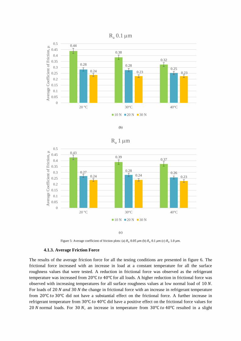
4.1.2. Average Coefficient of Friction
The results of the average coefficient of friction for all testing conditions are presented in figure 5.
The data revealed a similar pattern for all investigated surface roughness values. With an increase in
0
0.1
0.2
0.3
0.4
0.5
0.6
0 1000 2000 3000 4000 5000 6000 7000 8000Fri
ctio
n C
oef
fici
ent,
Time, s
Ra 1 m, Temperature 30°C
10 N 20 N 30 N
0
0.1
0.2
0.3
0.4
0.5
0.6
0 1000 2000 3000 4000 5000 6000 7000 8000Fri
ctio
n C
oef
fici
ent,
Time, s
Ra 1 m, Temperature 40°C
10 N 20 N 30 N
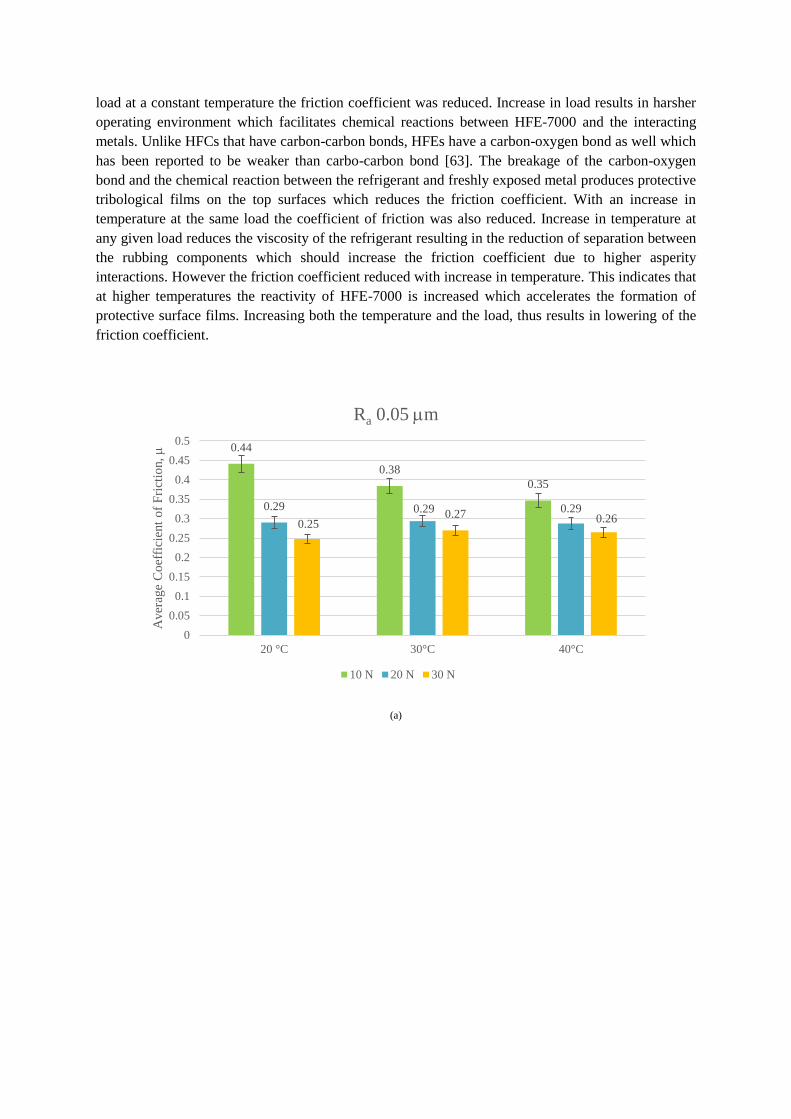
load at a constant temperature the friction coefficient was reduced. Increase in load results in harsher
operating environment which facilitates chemical reactions between HFE-7000 and the interacting
metals. Unlike HFCs that have carbon-carbon bonds, HFEs have a carbon-oxygen bond as well which
has been reported to be weaker than carbo-carbon bond [63]. The breakage of the carbon-oxygen
bond and the chemical reaction between the refrigerant and freshly exposed metal produces protective
tribological films on the top surfaces which reduces the friction coefficient. With an increase in
temperature at the same load the coefficient of friction was also reduced. Increase in temperature at
any given load reduces the viscosity of the refrigerant resulting in the reduction of separation between
the rubbing components which should increase the friction coefficient due to higher asperity
interactions. However the friction coefficient reduced with increase in temperature. This indicates that
at higher temperatures the reactivity of HFE-7000 is increased which accelerates the formation of
protective surface films. Increasing both the temperature and the load, thus results in lowering of the
friction coefficient.
(a)
0.44
0.38
0.35
0.29 0.29 0.29
0.25 0.27 0.26
0
0.05
0.1
0.15
0.2
0.25
0.3
0.35
0.4
0.45
0.5
20 °C 30°C 40°C
Aver
age
Co
effi
cien
t o
f F
rict
ion,
Ra 0.05 m
10 N 20 N 30 N
(b)
(c)
Figure 5: Average coefficient of friction plots: (a) (b) (c) .
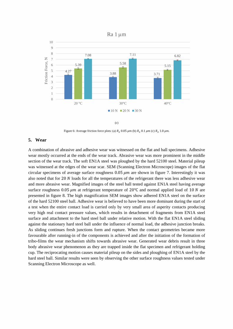
4.1.3. Average Friction Force
The results of the average friction force for all the testing conditions are presented in figure 6. The
frictional force increased with an increase in load at a constant temperature for all the surface
roughness values that were tested. A reduction in frictional force was observed as the refrigerant
temperature was increased from for all loads. A higher reduction in frictional force was
observed with increasing temperatures for all surface roughness values at low normal load of .
For loads of the change in frictional force with an increase in refrigerant temperature
from did not have a substantial effect on the frictional force. A further increase in
refrigerant temperature from did have a positive effect on the frictional force values for
normal loads. For , an increase in temperature from resulted in a slight
0.44
0.38
0.32
0.28 0.28 0.25
0.24 0.23 0.23
0
0.05
0.1
0.15
0.2
0.25
0.3
0.35
0.4
0.45
0.5
20 °C 30°C 40°C
Aver
age
Co
effi
cien
t o
f F
rict
ion,
Ra 0.1 m
10 N 20 N 30 N
0.43
0.39 0.37
0.27 0.28 0.26
0.24 0.24 0.23
0
0.05
0.1
0.15
0.2
0.25
0.3
0.35
0.4
0.45
0.5
20 °C 30°C 40°C
Aver
age
Co
effi
cien
t o
f F
rict
ion,
Ra 1 m
10 N 20 N 30 N
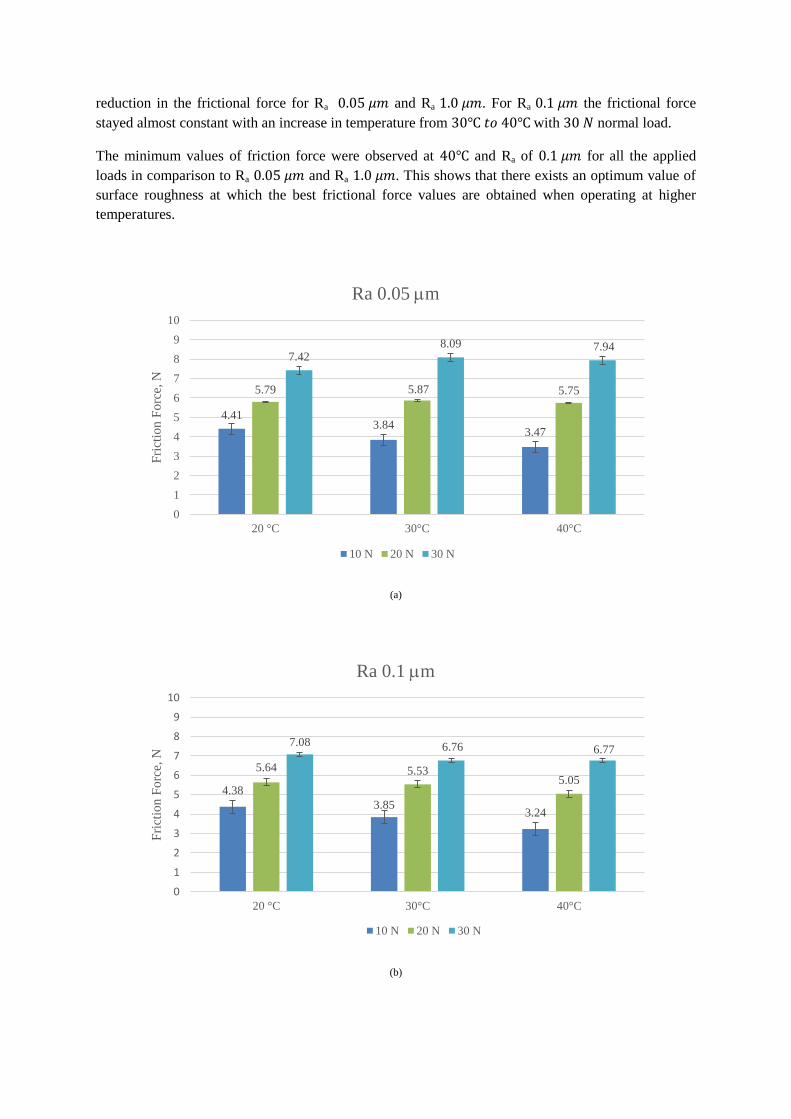
reduction in the frictional force for Ra and Ra . For Ra the frictional force
stayed almost constant with an increase in temperature from with normal load.
The minimum values of friction force were observed at and Ra of for all the applied
loads in comparison to Ra and Ra . This shows that there exists an optimum value of
surface roughness at which the best frictional force values are obtained when operating at higher
temperatures.
(a)
(b)
4.41 3.84
3.47
5.79 5.87 5.75
7.42 8.09 7.94
0
1
2
3
4
5
6
7
8
9
10
20 °C 30°C 40°C
Fri
ctio
n F
orc
e, N
Ra 0.05 m
10 N 20 N 30 N
4.38
3.85 3.24
5.64 5.53 5.05
7.08 6.76 6.77
0
1
2
3
4
5
6
7
8
9
10
20 °C 30°C 40°C
Fri
ctio
n F
orc
e, N
Ra 0.1 m
10 N 20 N 30 N
(c)
Figure 6: Average friction force plots: (a) (b) (c) .
5. Wear
A combination of abrasive and adhesive wear was witnessed on the flat and ball specimens. Adhesive
wear mostly occurred at the ends of the wear track. Abrasive wear was more prominent in the middle
section of the wear track. The soft EN1A steel was ploughed by the hard 52100 steel. Material pileup
was witnessed at the edges of the wear scar. SEM (Scanning Electron Microscope) images of the flat
circular specimens of average surface roughness are shown in figure 7. Interestingly it was
also noted that for loads for all the temperatures of the refrigerant there was less adhesive wear
and more abrasive wear. Magnified images of the steel ball tested against EN1A steel having average
surface roughness at refrigerant temperature of and normal applied load of are
presented in figure 8. The high magnification SEM images show adhered EN1A steel on the surface
of the hard 52100 steel ball. Adhesive wear is believed to have been more dominant during the start of
a test when the entire contact load is carried only by very small area of asperity contacts producing
very high real contact pressure values, which results in detachment of fragments from EN1A steel
surface and attachment to the hard steel ball under relative motion. With the flat EN1A steel sliding
against the stationary hard steel ball under the influence of normal load, the adhesive junction breaks.
As sliding continues fresh junctions form and rupture. When the contact geometries became more
favourable after running-in of the components is achieved and after the initiation of the formation of
tribo-films the wear mechanism shifts towards abrasive wear. Generated wear debris result in three
body abrasive wear phenomenon as they are trapped inside the flat specimen and refrigerant holding
cup. The reciprocating motion causes material pileup on the sides and ploughing of EN1A steel by the
hard steel ball. Similar results were seen by observing the other surface roughness values tested under
Scanning Electron Microscope as well.
4.27 3.88 3.71
5.39 5.58 5.15
7.08 7.11 6.82
0
1
2
3
4
5
6
7
8
9
10
20 °C 30°C 40°C
Fri
ctio
n F
orc
e, N
Ra 1 m
10 N 20 N 30 N
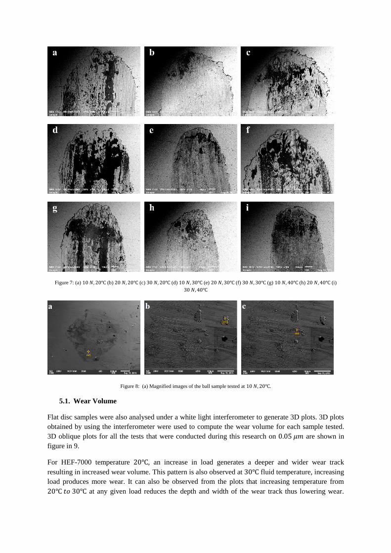
Figure 7: (a) (b) (c) (d) (e) (f) (g) (h) (i)
Figure 8: (a) Magnified images of the ball sample tested at .
5.1. Wear Volume
Flat disc samples were also analysed under a white light interferometer to generate 3D plots. 3D plots
obtained by using the interferometer were used to compute the wear volume for each sample tested.
3D oblique plots for all the tests that were conducted during this research on are shown in
figure in 9.
For HEF-7000 temperature , an increase in load generates a deeper and wider wear track
resulting in increased wear volume. This pattern is also observed at fluid temperature, increasing
load produces more wear. It can also be observed from the plots that increasing temperature from
at any given load reduces the depth and width of the wear track thus lowering wear.
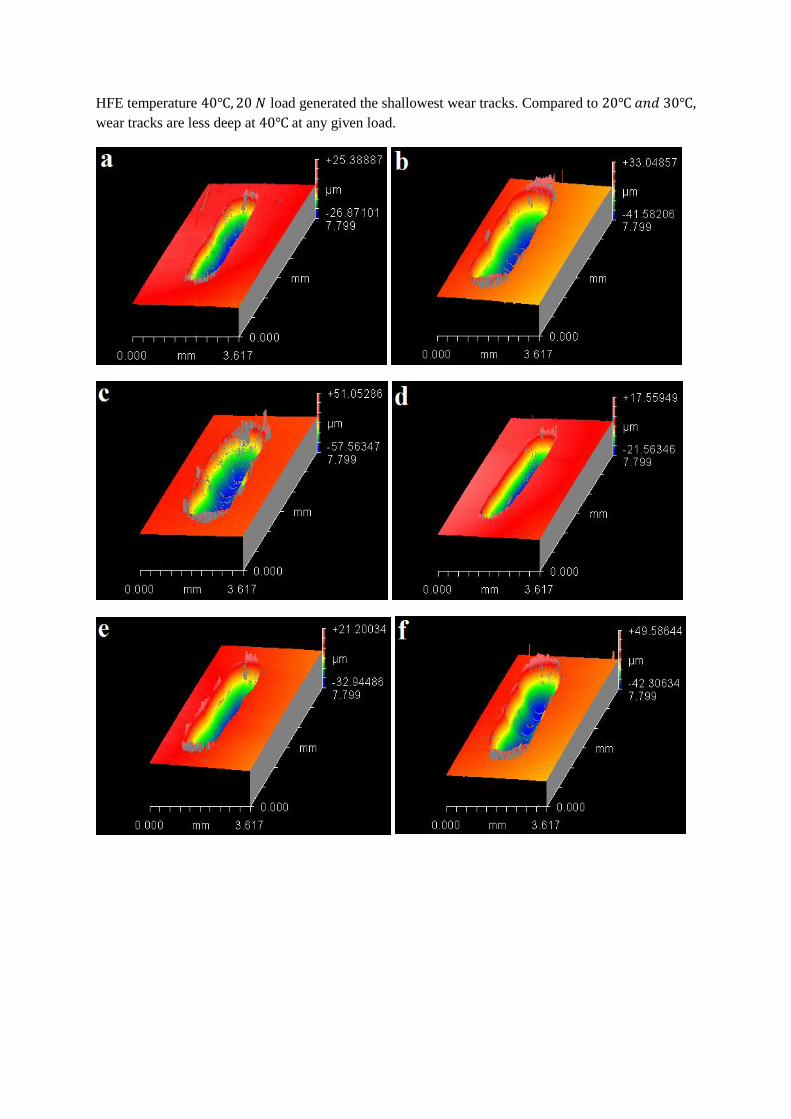
HFE temperature load generated the shallowest wear tracks. Compared to ,
wear tracks are less deep at at any given load.
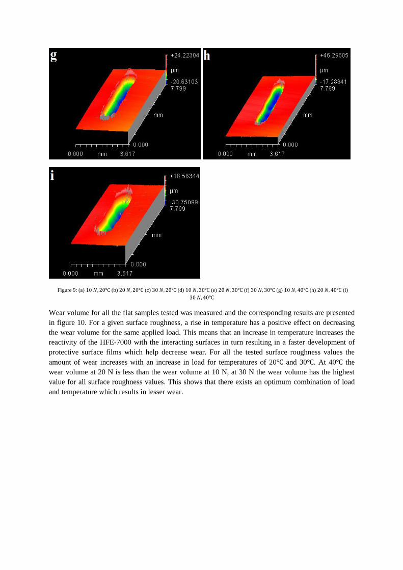
Figure 9: (a) (b) (c) (d) (e) (f) (g) (h) (i)
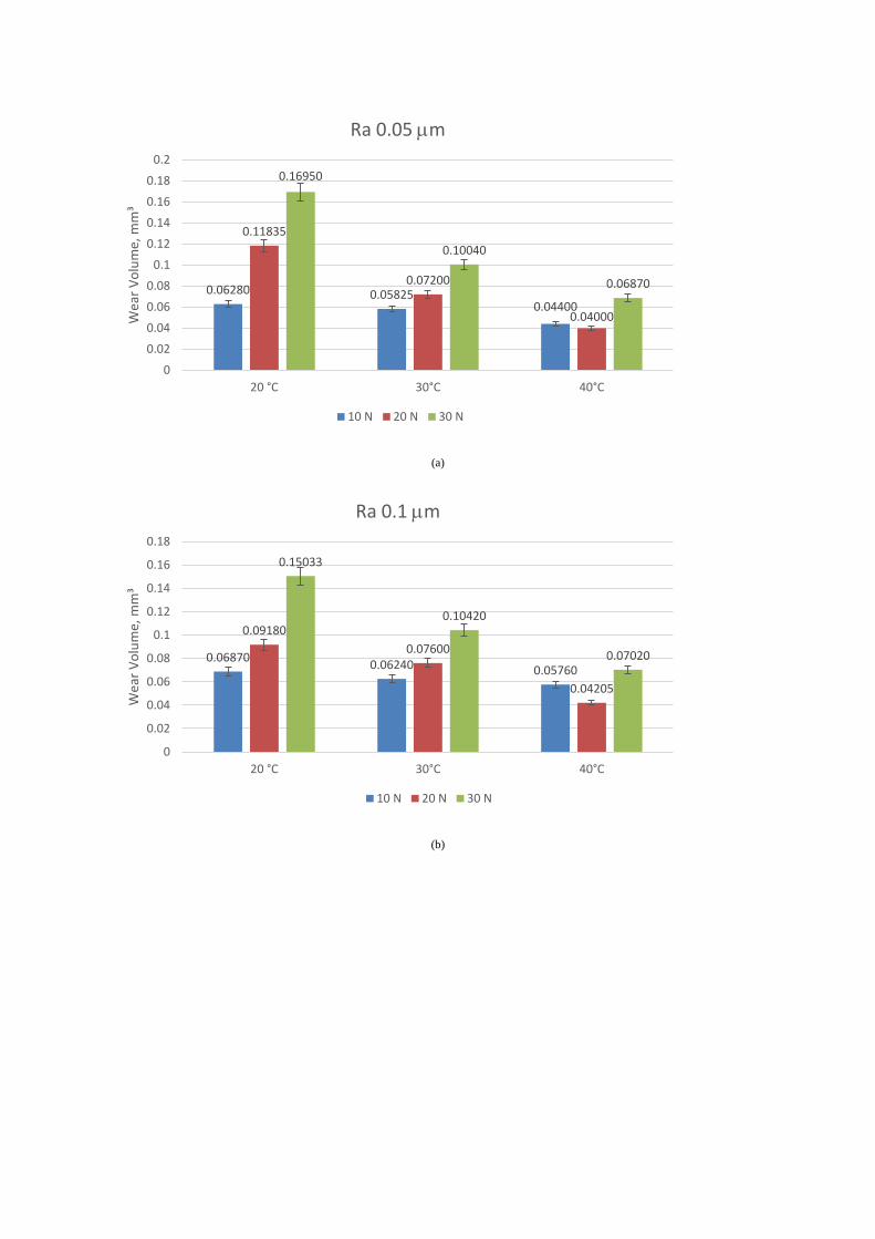
Wear volume for all the flat samples tested was measured and the corresponding results are presented
in figure 10. For a given surface roughness, a rise in temperature has a positive effect on decreasing
the wear volume for the same applied load. This means that an increase in temperature increases the
reactivity of the HFE-7000 with the interacting surfaces in turn resulting in a faster development of
protective surface films which help decrease wear. For all the tested surface roughness values the
amount of wear increases with an increase in load for temperatures of 20 and 30 . At 40 the
wear volume at 20 N is less than the wear volume at 10 N, at 30 N the wear volume has the highest
value for all surface roughness values. This shows that there exists an optimum combination of load
and temperature which results in lesser wear.
(a)
(b)
0.06280 0.05825 0.04400
0.11835
0.07200
0.04000
0.16950
0.10040
0.06870
0
0.02
0.04
0.06
0.08
0.1
0.12
0.14
0.16
0.18
0.2
20 °C 30°C 40°C
Wea
r V
olu
me,
mm
³ Ra 0.05 m
10 N 20 N 30 N
0.06870 0.06240 0.05760
0.09180
0.07600
0.04205
0.15033
0.10420
0.07020
0
0.02
0.04
0.06
0.08
0.1
0.12
0.14
0.16
0.18
20 °C 30°C 40°C
Wea
r V
olu
me,
mm
³
Ra 0.1 m
10 N 20 N 30 N
(c)
Figure 10: Wear volume plots: (a) (b) (c) .
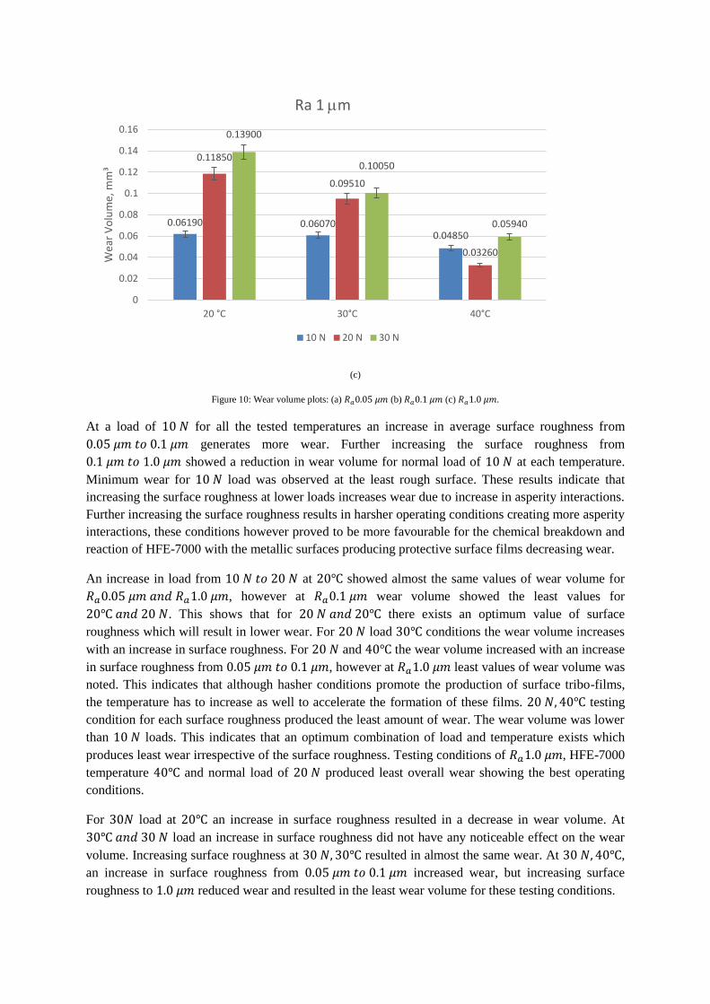
At a load of for all the tested temperatures an increase in average surface roughness from
generates more wear. Further increasing the surface roughness from
showed a reduction in wear volume for normal load of at each temperature.
Minimum wear for load was observed at the least rough surface. These results indicate that
increasing the surface roughness at lower loads increases wear due to increase in asperity interactions.
Further increasing the surface roughness results in harsher operating conditions creating more asperity
interactions, these conditions however proved to be more favourable for the chemical breakdown and
reaction of HFE-7000 with the metallic surfaces producing protective surface films decreasing wear.
An increase in load from at showed almost the same values of wear volume for
, however at wear volume showed the least values for
. This shows that for there exists an optimum value of surface
roughness which will result in lower wear. For load conditions the wear volume increases
with an increase in surface roughness. For and the wear volume increased with an increase
in surface roughness from , however at least values of wear volume was
noted. This indicates that although hasher conditions promote the production of surface tribo-films,
the temperature has to increase as well to accelerate the formation of these films. testing
condition for each surface roughness produced the least amount of wear. The wear volume was lower
than loads. This indicates that an optimum combination of load and temperature exists which
produces least wear irrespective of the surface roughness. Testing conditions of , HFE-7000
temperature and normal load of produced least overall wear showing the best operating
conditions.
For load at an increase in surface roughness resulted in a decrease in wear volume. At
load an increase in surface roughness did not have any noticeable effect on the wear
volume. Increasing surface roughness at resulted in almost the same wear. At ,
an increase in surface roughness from increased wear, but increasing surface
roughness to reduced wear and resulted in the least wear volume for these testing conditions.
0.06190 0.06070 0.04850
0.11850
0.09510
0.03260
0.13900
0.10050
0.05940
0
0.02
0.04
0.06
0.08
0.1
0.12
0.14
0.16
20 °C 30°C 40°C
Wea
r V
olu
me,
mm
³ Ra 1 m
10 N 20 N 30 N
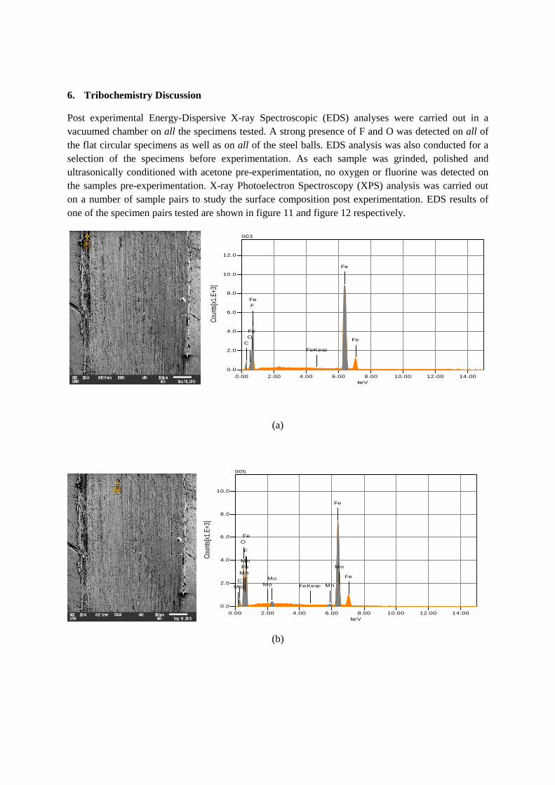
6. Tribochemistry Discussion
Post experimental Energy-Dispersive X-ray Spectroscopic (EDS) analyses were carried out in a
vacuumed chamber on all the specimens tested. A strong presence of F and O was detected on all of
the flat circular specimens as well as on all of the steel balls. EDS analysis was also conducted for a
selection of the specimens before experimentation. As each sample was grinded, polished and
ultrasonically conditioned with acetone pre-experimentation, no oxygen or fluorine was detected on
the samples pre-experimentation. X-ray Photoelectron Spectroscopy (XPS) analysis was carried out
on a number of sample pairs to study the surface composition post experimentation. EDS results of
one of the specimen pairs tested are shown in figure 11 and figure 12 respectively.
(a)
(b)
keV
0.00 2.00 4.00 6.00 8.00 10.00 12.00 14.00
Cou
nts[
x1.E
+3]
0.0
2.0
4.0
6.0
8.0
10.0
12.0
003
C
O
Fe
F
Fe
FeKesc
Fe
Fe
keV
0.00 2.00 4.00 6.00 8.00 10.00 12.00 14.00
Cou
nts[
x1.E
+3]
0.0
2.0
4.0
6.0
8.0
10.0
005
Mo
C
O
Mn
Fe
Mn
F
Fe
Mo
Mo
FeKesc Mn
Fe
Mn
Fe
(c)
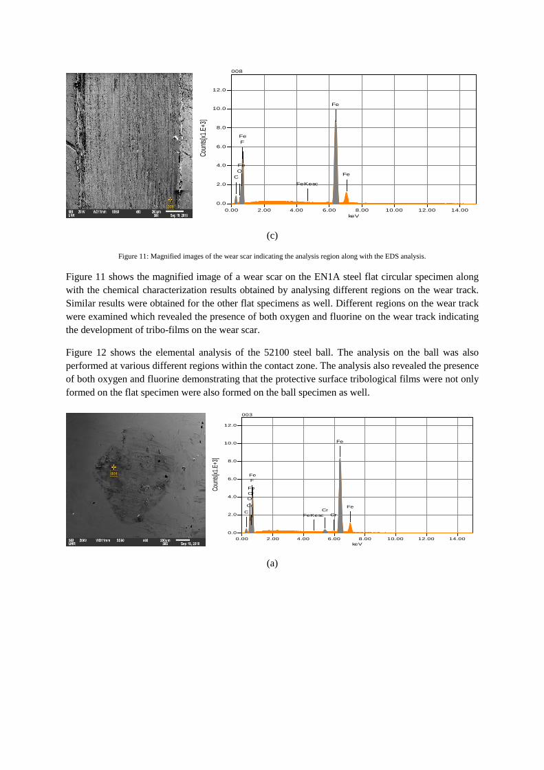
Figure 11: Magnified images of the wear scar indicating the analysis region along with the EDS analysis.
Figure 11 shows the magnified image of a wear scar on the EN1A steel flat circular specimen along
with the chemical characterization results obtained by analysing different regions on the wear track.
Similar results were obtained for the other flat specimens as well. Different regions on the wear track
were examined which revealed the presence of both oxygen and fluorine on the wear track indicating
the development of tribo-films on the wear scar.
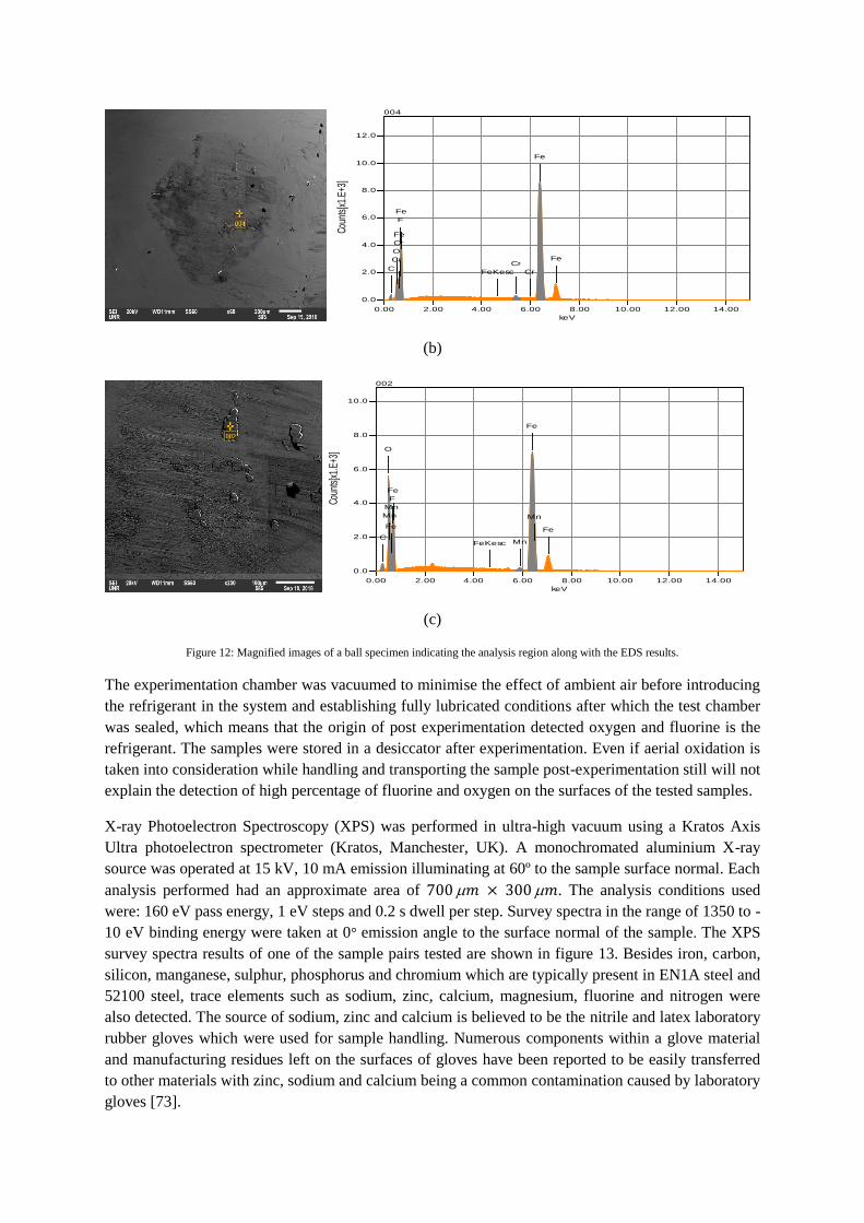
Figure 12 shows the elemental analysis of the 52100 steel ball. The analysis on the ball was also
performed at various different regions within the contact zone. The analysis also revealed the presence
of both oxygen and fluorine demonstrating that the protective surface tribological films were not only
formed on the flat specimen were also formed on the ball specimen as well.
(a)
keV
0.00 2.00 4.00 6.00 8.00 10.00 12.00 14.00
Coun
ts[x
1.E+
3]0.0
2.0
4.0
6.0
8.0
10.0
12.0
008
C
O
Fe
F
Fe
FeKesc
Fe
Fe
keV
0.00 2.00 4.00 6.00 8.00 10.00 12.00 14.00
Coun
ts[x
1.E+
3]
0.0
2.0
4.0
6.0
8.0
10.0
12.0
003
C
Cr
O
Cr
Fe
F
Fe
FeKesc
Cr
Cr
Fe
Fe
(b)
(c)
Figure 12: Magnified images of a ball specimen indicating the analysis region along with the EDS results.
The experimentation chamber was vacuumed to minimise the effect of ambient air before introducing
the refrigerant in the system and establishing fully lubricated conditions after which the test chamber
was sealed, which means that the origin of post experimentation detected oxygen and fluorine is the
refrigerant. The samples were stored in a desiccator after experimentation. Even if aerial oxidation is
taken into consideration while handling and transporting the sample post-experimentation still will not
explain the detection of high percentage of fluorine and oxygen on the surfaces of the tested samples.
X-ray Photoelectron Spectroscopy (XPS) was performed in ultra-high vacuum using a Kratos Axis
Ultra photoelectron spectrometer (Kratos, Manchester, UK). A monochromated aluminium X-ray
source was operated at 15 kV, 10 mA emission illuminating at 60º to the sample surface normal. Each
analysis performed had an approximate area of . The analysis conditions used
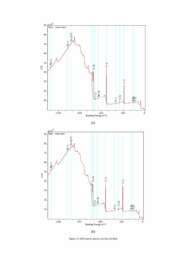
were: 160 eV pass energy, 1 eV steps and 0.2 s dwell per step. Survey spectra in the range of 1350 to -
10 eV binding energy were taken at 0° emission angle to the surface normal of the sample. The XPS
survey spectra results of one of the sample pairs tested are shown in figure 13. Besides iron, carbon,
silicon, manganese, sulphur, phosphorus and chromium which are typically present in EN1A steel and
52100 steel, trace elements such as sodium, zinc, calcium, magnesium, fluorine and nitrogen were
also detected. The source of sodium, zinc and calcium is believed to be the nitrile and latex laboratory
rubber gloves which were used for sample handling. Numerous components within a glove material
and manufacturing residues left on the surfaces of gloves have been reported to be easily transferred
to other materials with zinc, sodium and calcium being a common contamination caused by laboratory
gloves [73].
keV
0.00 2.00 4.00 6.00 8.00 10.00 12.00 14.00
Coun
ts[x
1.E+
3]
0.0
2.0
4.0
6.0
8.0
10.0
12.0
004
C
Cr
O
Cr
Fe
F
Fe
FeKesc
Cr
Cr
Fe
Fe
keV
0.00 2.00 4.00 6.00 8.00 10.00 12.00 14.00
Coun
ts[x
1.E+
3]
0.0
2.0
4.0
6.0
8.0
10.0
002
C
O
Mn
Fe
Mn
F
Fe
FeKesc Mn
Fe
Mn
Fe
(a)
(b)
Figure 13: XPS survey spectra: (a) Disc (b) Ball
Nitrogen is often associated with carbon contamination from the atmosphere and this is consistent
with the inelastic background of the C 1s peak which indicates that it is mainly a contaminant
overlayer. Elements of interest i.e. the constituents present in the refrigerant and steel samples were
further investigated and are presented in figure 14.
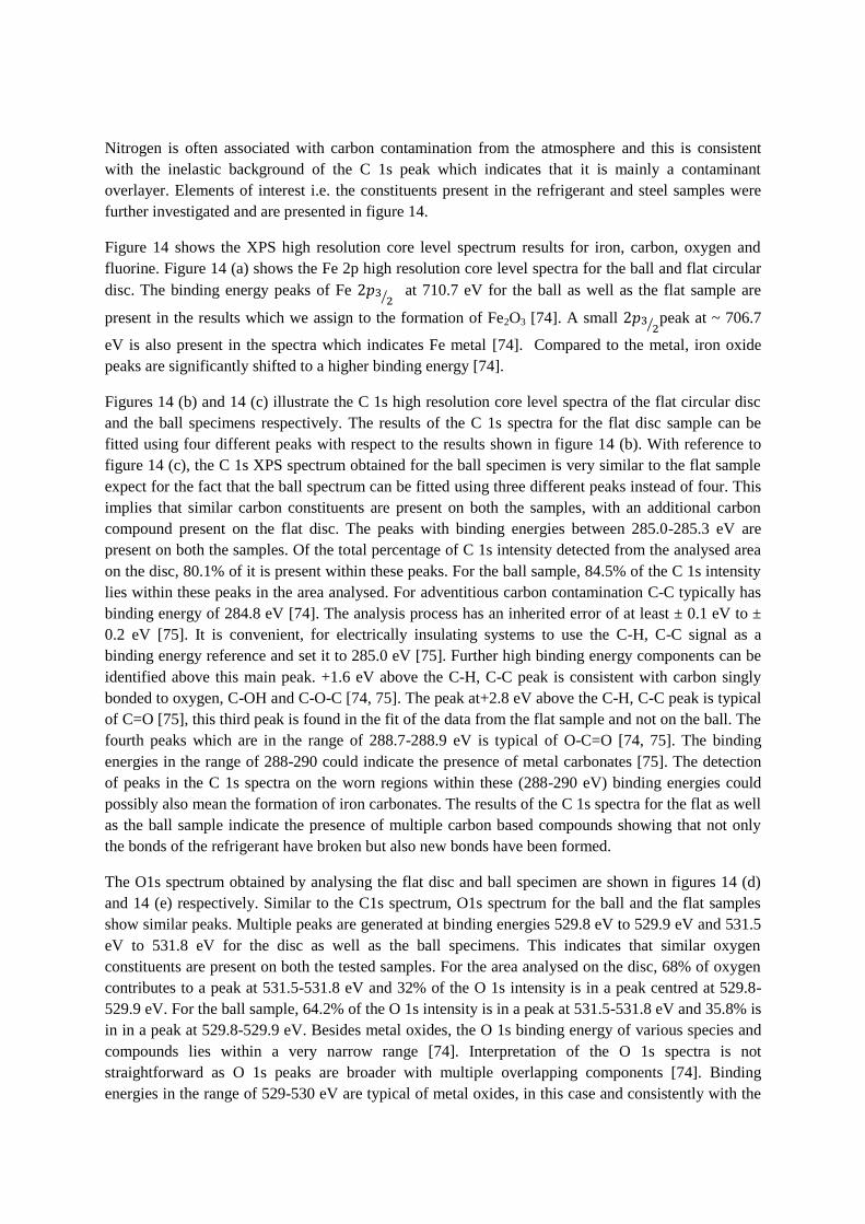
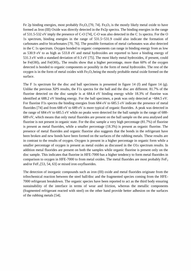
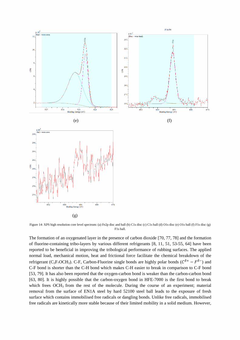
Figure 14 shows the XPS high resolution core level spectrum results for iron, carbon, oxygen and
fluorine. Figure 14 (a) shows the Fe 2p high resolution core level spectra for the ball and flat circular
disc. The binding energy peaks of Fe ⁄ at 710.7 eV for the ball as well as the flat sample are
present in the results which we assign to the formation of Fe2O3 [74]. A small ⁄peak at ~ 706.7
eV is also present in the spectra which indicates Fe metal [74]. Compared to the metal, iron oxide
peaks are significantly shifted to a higher binding energy [74].
Figures 14 (b) and 14 (c) illustrate the C 1s high resolution core level spectra of the flat circular disc
and the ball specimens respectively. The results of the C 1s spectra for the flat disc sample can be
fitted using four different peaks with respect to the results shown in figure 14 (b). With reference to
figure 14 (c), the C 1s XPS spectrum obtained for the ball specimen is very similar to the flat sample
expect for the fact that the ball spectrum can be fitted using three different peaks instead of four. This
implies that similar carbon constituents are present on both the samples, with an additional carbon
compound present on the flat disc. The peaks with binding energies between 285.0-285.3 eV are
present on both the samples. Of the total percentage of C 1s intensity detected from the analysed area
on the disc, 80.1% of it is present within these peaks. For the ball sample, 84.5% of the C 1s intensity
lies within these peaks in the area analysed. For adventitious carbon contamination C-C typically has
binding energy of 284.8 eV [74]. The analysis process has an inherited error of at least ± 0.1 eV to ±
0.2 eV [75]. It is convenient, for electrically insulating systems to use the C-H, C-C signal as a
binding energy reference and set it to 285.0 eV [75]. Further high binding energy components can be
identified above this main peak. +1.6 eV above the C-H, C-C peak is consistent with carbon singly
bonded to oxygen, C-OH and C-O-C [74, 75]. The peak at+2.8 eV above the C-H, C-C peak is typical
of C=O [75], this third peak is found in the fit of the data from the flat sample and not on the ball. The
fourth peaks which are in the range of 288.7-288.9 eV is typical of O-C=O [74, 75]. The binding
energies in the range of 288-290 could indicate the presence of metal carbonates [75]. The detection
of peaks in the C 1s spectra on the worn regions within these (288-290 eV) binding energies could
possibly also mean the formation of iron carbonates. The results of the C 1s spectra for the flat as well
as the ball sample indicate the presence of multiple carbon based compounds showing that not only
the bonds of the refrigerant have broken but also new bonds have been formed.
The O1s spectrum obtained by analysing the flat disc and ball specimen are shown in figures 14 (d)
and 14 (e) respectively. Similar to the C1s spectrum, O1s spectrum for the ball and the flat samples
show similar peaks. Multiple peaks are generated at binding energies 529.8 eV to 529.9 eV and 531.5
eV to 531.8 eV for the disc as well as the ball specimens. This indicates that similar oxygen
constituents are present on both the tested samples. For the area analysed on the disc, 68% of oxygen
contributes to a peak at 531.5-531.8 eV and 32% of the O 1s intensity is in a peak centred at 529.8-
529.9 eV. For the ball sample, 64.2% of the O 1s intensity is in a peak at 531.5-531.8 eV and 35.8% is
in in a peak at 529.8-529.9 eV. Besides metal oxides, the O 1s binding energy of various species and
compounds lies within a very narrow range [74]. Interpretation of the O 1s spectra is not
straightforward as O 1s peaks are broader with multiple overlapping components [74]. Binding
energies in the range of 529-530 eV are typical of metal oxides, in this case and consistently with the
Fe 2p binding energies, most probably Fe2O3 [70, 74]. Fe2O3 is the mostly likely metal oxide to have
formed as Iron (III) Oxide was directly detected in the Fe2p spectra. The binding energies in the range
of 531.5-532 eV imply the presence of C-O [74], C-O was also detected in the C 1s spectra. For the O
1s spectrum, binding energies in the range of 531.5~531.9 could also indicate the formation of
carbonates and/or bicarbonates [70, 76]. The possible formation of metal carbonates was also detected
in the C 1s spectrum. Oxygen bonded to organic components can range in binding energy from as low
as 530.9 eV to as high as 533.8 eV and metal hydroxides are reported to have a binding energy of
531.3 eV with a standard deviation of 0.3 eV [75]. The most likely metal hydroxides, if present, could
be Fe(OH)2 and Fe(OH)3. The results show that a higher percentage, more than 60% of the oxygen
detected is bonded to organic components or possibly in the form of metal hydroxides. The rest of the
oxygen is in the form of metal oxides with Fe2O3 being the mostly probable metal oxide formed on the
surface.
The F 1s spectrum for the disc and ball specimens is presented in figure 14 (f) and figure 14 (g).
Unlike the previous XPS results, the F1s spectra for the ball and the disc are different. 81.7% of the
fluorine detected on the disc sample is at 684.4 eV binding energy while 18.3% of fluorine was
identified at 688.2 eV binding energy. For the ball specimen, a peak was only detected at ~684.5 eV.
For fluorine F1s spectra the binding energies from 684 eV to 685.5 eV indicate the presence of metal
fluorides [74] and from 688 eV to 689 eV is more typical of organic fluorides. A peak was detected in
the range of 684 eV to 685.5 eV while no peaks were detected for the ball sample in the range of 688-
689 eV, which means that only metal fluorides are present on the ball sample on the area analysed and
fluorine is not present in organic state. For the disc sample a very high percentage (81.7%) of fluorine
is present as metal fluorides, while a smaller percentage (18.3%) is present as organic fluorine. The
presence of metal fluorides and organic fluorine also suggests that the bonds in the refrigerant have
been broken and new bonds have been formed on the surfaces of the rubbing metals. These results are
in contrast to the results of oxygen. Oxygen is present in a higher percentage in organic form while a
smaller percentage of oxygen is present as metal oxides as discussed in the O1s spectrum results. In
addition metal fluorides are present on both the samples while organic fluorine is present only on the
disc sample. This indicates that fluorine in HFE-7000 has a higher tendency to form metal fluorides in
comparison to oxygen in HFE-7000 to from metal oxides. The metal fluorides are most probably FeF2
and/or FeF3 [53, 54, 63] or mixed iron oxyfluorides.
The detection of inorganic compounds such as iron (III) oxide and metal fluorides originate from the
tribochemical reaction between the steel ball/disc and the fragmented species coming from the HFE-
7000 refrigerant breakdown. The organic species have been reported to act as the third body ensuring
sustainability of the interface in terms of wear and friction, whereas the metallic components
(fragmented refrigerant reacted with steel) on the other hand provide better adhesion on the surfaces
of the rubbing metals [54].
(a) (b)
(c) (d)
(e) (f)
(g)
Figure 14: XPS high resolution core level spectrum: (a) Fe2p disc and ball (b) C1s disc (c) C1s ball (d) O1s disc (e) O1s ball (f) F1s disc (g)
F1s ball.
The formation of an oxygenated layer in the presence of carbon dioxide [70, 77, 78] and the formation
of fluorine-containing tribo-layers by various different refrigerants [8, 11, 51, 53-55, 64] have been
reported to be beneficial in improving the tribological performance of rubbing surfaces. The applied
normal load, mechanical motion, heat and frictional force facilitate the chemical breakdown of the
refrigerant (C3F7OCH3). C-F, Carbon-Fluorine single bonds are highly polar bonds ( ) and
C-F bond is shorter than the C-H bond which makes C-H easier to break in comparison to C-F bond
[53, 79]. It has also been reported that the oxygen-carbon bond is weaker than the carbon-carbon bond
[63, 80]. It is highly possible that the carbon-oxygen bond in HFE-7000 is the first bond to break
which frees OCH3 from the rest of the molecule. During the course of an experiment; material
removal from the surface of EN1A steel by hard 52100 steel ball leads to the exposure of fresh
surface which contains immobilised free radicals or dangling bonds. Unlike free radicals, immobilised
free radicals are kinetically more stable because of their limited mobility in a solid medium. However,
similar to free radicals, immobilised free radicals are also extremely reactive. The breakdown of
refrigerant and the exposure of fresh highly reactive bonds on the surface of the EN1A steel specimen
leads to a chemical reaction between the refrigerant and EN1A steel. This leads to the adsorption of
HFE-7000 on to the surfaces therefore forming oxygenated and fluorinated tribo-films which results
in reduction in friction and wear. Besides the adhered softer material on the ball, scratch marks are
also clearly visible on the surface of the ball in the contact region, which leads to a similar chemical
reaction between the ball the refrigerant as well. These tribo-layers are well adhered to the rubbing
surface as the presence of fluorine and oxygen was not only detected throughout the wear scar on the
disc specimen but was also detected on different contact regions on the ball specimen.
7. Conclusions
A micro friction machine has been successfully modified and commissioned for bench testing the
future generation of refrigerants within tribological context. A series of testes have been conducted to
assess the tribological performance of the environmentally friendly refrigerant HFE-7000 by varying
the tribo-operating conditions. Variable operating environments have been simulated during this
study. Tests have been performed by changing the applied normal load, by using samples of various
surface finish and by heating the refrigerant to various temperatures. HFE-7000 has a wide ranging
application areas and the tribological performance of the refrigerant has been investigated at low loads
and low temperatures starting from room temperature. The results have shown that a mechanical
system based on HFE-7000 will show good friction and wear performance at higher operating
temperatures and loads, in addition HFE 7000 exhibits good tribological performance at lower
temperatures and low loads as well. An increase in load even at results in a significant reduction
in the friction coefficient and the increase in temperature at a low load of even reduces wear.
Overall the results indicate that increasing the operating temperature at a constant load reduces both
friction coefficient and wear. Increasing the load at a constant temperature increases wear but results
in a reduction in friction coefficient. The reduction in the friction coefficient with increasing load and
decrease in wear along with a decrease in coefficient of friction with increasing temperature is
believed to be associated with the development of protective tribo-films on the interacting surfaces.
The formation of these films is accelerated by an elevation in the refrigerant temperature and increase
in the applied load. Increasing the applied load and operating temperature increases the reactivity of
the refrigerant HFE-7000 with the rubbing metals. EDS analyses on the samples in the contact region
and wear track have shown a significant presence of oxygen, fluorine and carbon on the rubbing
surfaces. The detailed high resolution XPS analysis reveal the formation of new bonds/compounds on
the surfaces of the interacting metals and indicate breaking up of the bonds of the refrigerant. Analysis
on different regions within the contact zone of the rubbing metals post-experimentation has
demonstrated that oxygenated and fluorinated layers are well adhered on the disc wear track and ball.
It is also observed from the results obtained that the surface roughness does not have a very
significant effect on the coefficient of friction and on wear. This shows that metallic parts of a range
of surface finish and even parts with rough surface finish can be used in HFE-7000 run interacting
systems.
The results of this study show that HFE-7000 which is a promising future generation refrigerant from
a thermodynamics point of view has demonstrated good tribological performance. It can be inferred
with confidence evidenced by the results presented here, that HFE-7000 based interacting systems
will show better friction and wear performance as compared to their predecessors HFCs.
Acknowledgments:
The authors would like to acknowledge financial and in-kind support provided by National University
of Sciences & Technology (NUST) Islamabad Pakistan and Bournemouth University United
Kingdom. The authors would also like to acknowledge Steve Spencer and Alex Shard from National
Physical Laboratory, Teddington, Middlesex, United Kingdom for conducting XPS analysis and for
providing valuable guidance & feedback in explaining its results.
References
[1] J.T. McMullan, Refrigeration and the environment — issues and strategies for the future, international Journal of Refrigeration, vol. 25, no. 1, pp. 89-99, 2002/01/01/ 2002, doi: 10.1016/S0140-7007(01)00007-X.
[2] B. Xiang, P.K. Patra, S.A. Montzka, S.M. Miller, J.W. Elkins, F.L. Moore, E.L. Atlas, B.R. Miller, R.F. Weiss, R.G. Prinn, S.C. Wofsy, Global emissions of refrigerants HCFC-22 and HFC-134a: Unforeseen seasonal contributions, Proceedings of the National Academy of Sciences, vol. 111, no. 49, pp. 17379-17384, 2014, 10.1073/pnas.1417372111.
[3] M.U. Bhutta, Z.A. Khan, N.P. Garland, A. Ghafoor, A Historical Review on the Tribological Performance of Refrigerants used in Compressors, Tribology in Industry, vol. 40, no. 1, pp. 19-51, 2018, 10.24874/ti.2018.40.01.03.
[4] J.M. Calm, The next generation of refrigerants–Historical review, considerations, and outlook, international Journal of Refrigeration, vol. 31, no. 7, pp. 1123-1133, 2008, doi: 10.1016/j.ijrefrig.2008.01.013.
[5] S. Jollev, New and Unique Lubricants for Use in Compressors Utilizing R-134a Refrigerant, in International Refrigeration and Air Conditioning Conference, Purdue University, Indiana, USA, 17-20 July, 1990, Paper 96.
[6] B. Davis, T.K. Sheiretov, C. Cusano, Tribological Evaluation of Contacts Lubricated by Oil-Refrigerant Mixtures, in Air Conditioning and Refrigeration Center, College of Engineering, University of Illinois at Urbana-Champaign, USA, ACRC Technical Report 19, May 1992.
[7] S. KOMATSUZAKI, Y. HOMMA, Lubricants for HFC Refrigerant Compressors, Journal of The Japan Petroleum Institute, vol. 37, no. 3, pp. 226-235, 1994, 10.1627/jpi1958.37.226.
[8] K. Mizuhara, M. Akei, T. Matsuzaki, The friction and wear behavior in controlled alternative refrigerant atmosphere, Tribology Transactions, vol. 37, no. 1, pp. 120-128, 1994, 10.1080/10402009408983274.
[9] T. Sheiretov, W.V. Glabbeek, C. Cusano, Tribological evaluation of various surface treatments for M2 tool steel in a refrigerant environment, in International Compressor Engineering Conference, Purdue University, Indiana, USA, 19-22 July, 1994, Paper 964.
[10] M. Akei, K. Mizuhara, T. Taki, T. Yamamoto, Evaluation of film-forming capability of refrigeration lubricants in pressurized refrigerant atmosphere, Wear, vol. 196, no. 1-2, pp. 180-187, 1996, 10.1016/0043-1648(95)06917-8.
[11] K. Kawahara, S. Mishina, A. Kamino, K. Ochiai, T. Okawa, S. Fujimoto, Tribological Evaluation of Rotary Compressor with HFC Refrigerants, in International Compressor Engineering Conference, Purdue University, Indiana, USA, 23-26 July, 1996, Paper 1141.
[12] S. Fujimoto, K. Sakitani, M. Watada, Tribology Analysis in Rolling Piston Type Compressor, in International Compressor Engineering Conference, Purdue University, Indiana, USA, 1984, Paper 477.
[13] M. Muraki, K. Tagawa, D. Dong, Refrigeration Lubricant Based on Polyolester for Use With HFCs and Prospect of Its Application With R-22 (Part 1) Tribological Characteristics, in International Refrigeration and Air Conditioning Conference, Purdue University, Indiana, USA, 23-26 July, 1996, Paper 336.
[14] R. Tuomas, O. Isaksson, Measurement of lubrication conditions in a rolling element bearing in a refrigerant environment, Industrial Lubrication and Tribology, vol. 61, no. 2, pp. 91-99, 2009, 10.1108/00368790910940419.
[15] M.J. Molina, F.S. Rowland, Stratospheric sink for chlorofluoromethanes: chlorine atom-catalysed destruction of ozone, Nature, vol. 249, no. 5460, pp. 810-812, 1974.
[16] U. Nations, Montreal Protocol on Substances that Deplete the Ozone Layer, in United Nations Environment Programme, Montreal, Canada, 16 September 1987.
[17] D.P. Wilson, R.S. Basu, Thermodynamic properties of a new stratospherically safe working fluid-refrigerant 134a, in ASHRAE transactions, 1988, pp. Pages 2095-2118.
[18] I.R. Shankland, R.S. Basu, D.P. Wilson, Thermal conductivity and viscosity of a new stratospherically safe refrigerant-1, 1, 1, 2-tetrafluoroethane (R-134a), in International Refrigeration and Air Conditioning Conference, Purdue University, Indiana, USA, 1988, Paper 41.
[19] H. Spauschus, HFC 134a as a substitute refrigerant for CFC 12, international Journal of Refrigeration, vol. 11, no. 6, pp. 389-392, 1988, 10.1016/0140-7007(88)90063-1.
[20] S.J. Eckels, M.B. Pate, An experimental comparison of evaporation and condensation heat transfer coefficients for HFC-134a and CFC-12, international Journal of Refrigeration, vol. 14, no. 2, pp. 70-77, 1991, 10.1016/0140-7007(91)90078-U.
[21] S.H. Khan, S.M. Zubair, Thermodynamic analyses of the CFC-12 and HFC-134a refrigeration cycles, Energy, vol. 18, no. 7, pp. 717-726, 1993, 10.1016/0360-5442(93)90031-8.
[22] S. Kitaichi, S. Sato, R. Ishidoya, T. Machida, Tribological Analysis of Metal Interface Reactions in Lubricant Oils/CFC12 and HFC 134a System, in International Refrigeration and Air Conditioning Conference, 17-20 July, 1990, Purdue University, Indiana, USA, paper 97.
[23] B.C. Na, K.J. Chun, D.-C. Han, A tribological study of refrigeration oils under HFC-134a environment, Tribology International, vol. 30, no. 9, pp. 707-716, 1997, 10.1016/S0301-679X(97)00072-8.
[24] Y. Yamamoto, S. Gondo, Friction and wear characteristics of lubricants for alternative refrigerant HFC 134a, JSME International Journal Series C Mechanical Systems, Machine Elements and Manufacturing, vol. 41, no. 2, pp. 278-284, 1998, doi: 10.1299/jsmec.41.278.
[25] M. Takesue, S. Tominaga, Wear and Scuffing Characteristics of Polyvinylether (PVE) in an HFC Atmosphere, in International Refrigeration and Air Conditioning Conference, 14-17 July, 1998, Purdue University, Indiana, USA, paper 440.
[26] H. Yoon, T. Sheiretov, C. Cusano, Tribological evaluation of some aluminum-based materials in lubricant/refrigerant mixtures, Wear, vol. 218, no. 1, pp. 54-65, 1998, doi: 10.1016/S0043-1648(98)00195-1.
[27] T. Sheiretov, H. Yoon, C. Cusano, Tribological Evaluation of Various Aluminum Alloys in Lubricant/Refrigerant Mixtures, Air Conditioning and Refrigeration Center, College of Engineering, University of Illinois at Urbana-Champaign, ACRC Technical Report 92, 1996.
[28] C. Ciantar, M. Hadfield, A. Smith, A. Swallow, The influence of lubricant viscosity on the wear of hermetic compressor components in HFC-134a environments, Wear, vol. 236, no. 1, pp. 1-8, 1999, doi: 10.1016/S0043-1648(99)00267-7.
[29] C. Ciantar, M. Hadfield, A. Swallow, A. Smith, The influence of POE and PVE lubricant blends within hermetic refrigerating compressors operating with HFC-134a refrigerant, Wear, vol. 241, no. 1, pp. 53-64, 2000, doi: 10.1016/S0043-1648(00)00361-6.
[30] H. Fukui, K.-i. Sanechika, M. Ikeda, Novel refrigeration lubricants for use with HFC refrigerants, Tribology International, vol. 33, no. 10, pp. 707-713, 2000, doi: 10.1016/S0301-679X(00)00107-9.
[31] Y. Yamamoto, S. Gondo, J. Kim, Solubility of HFC134a in Lubricants and Its Influence on Tribological Performance, Tribology Transactions, vol. 44, no. 2, pp. 209-214, 2001, doi: 10.1080/10402000108982450.
[32] C. Ciantar, M. Hadfield, A study of tribological durability with associated environmental impacts of a domestic refrigerator, Materials & Design, vol. 25, no. 4, pp. 331-341, 2004, doi: 10.1016/j.matdes.2003.10.016.
[33] Y.-Z. Lee, S.-D. Oh, Friction and wear of the rotary compressor vane–roller surfaces for several sliding conditions, Wear, vol. 255, no. 7–12, pp. 1168-1173, 2003, doi: 10.1016/S0043-1648(03)00278-3.
[34] F. Wardle, B. Jacobson, H. Dolfsma, E. Hoglund, U. Jonsson, The effect of refrigerants on the lubrication of rolling element bearings used in screw compressors, in International Compressor Engineering Conference, Purdue University, Indiana, USA, 14-17 July, 1992, Paper 843.
[35] B. Jacobson, Lubrication of Screw Compressor Bearings in the Presence of Refrigerants, in International Compressor Engineering Conference, Purdue University, Indiana, USA, 19-22 July, 1994, Paper 966.
[36] T. Hamada, N. Nishiura, Refrigeration lubricant based on polyolester for use with HFCs and prospect of its application with R-22 (Part 2) Hydrolytic stability and compressor endurance test results, in International Refrigeration and Air Conditioning Conference, Purdue University, Indiana, USA, 23-26 July, 1996, Paper 337.
[37] B. Jacobson, Ball Bearing Lubrication in Refrigetation Compressors, in International Compressor Engineering Conference, Purdue University, Indiana, USA, 23-26 July, 1996, Paper 1090.
[38] M. Akei, K. Mizuhara, The Elastohydrodynamic Properties of Lubricants in Refrigerant Environments©, Tribology Transactions, vol. 40, no. 1, pp. 1-10, 1997, 10.1080/10402009708983622.
[39] B.O. Jacobson, G.E.M. Espejel, High pressure investigation of refrigerants HFC245fa, R134a and R123, in International Compressor Engineering Conference, Purdue University, Indiana, USA, 17-20 July, 2006, Paper 1789.
[40] R. Tuomas, O. Isaksson, Compressibility of Oil/Refrigerant Lubricants in Elasto-Hydrodynamic Contacts, Journal of Tribology, vol. 128, no. 1, pp. 218-220, 2005, 10.1115/1.2125967.
[41] C. Breidenich, D. Magraw, A. Rowley, J.W. Rubin, The Kyoto protocol to the United Nations framework convention on climate change, American Journal of International Law, vol. 92, no. 2, pp. 315-331, 1998, doi: 10.2307/2998044.
[42] N. Garland, M. Hadfield, Environmental implications of hydrocarbon refrigerants applied to the hermetic compressor, Materials & Design, vol. 26, no. 7, pp. 578-586, 2005, 10.1016/j.matdes.2004.08.009.
[43] Z.A. Khan, M. Hadfield, Y. Wang, Pressurised chamber design for conducting rolling contact experiments with liquid refrigerant lubrication, Materials & Design, vol. 26, no. 8, pp. 680-689, 2005, 10.1016/j.matdes.2004.08.006.
[44] Z.A. Khan, M. Hadfield, S. Tobe, Y. Wang, Ceramic rolling elements with ring crack defects—A residual stress approach, Materials Science and Engineering: A, vol. 404, no. 1, pp. 221-226, 2005, 10.1016/j.msea.2005.05.087.
[45] Z.A. Khan, M. Hadfield, S. Tobe, Y. Wang, Residual stress variations during rolling contact fatigue of refrigerant lubricated silicon nitride bearing elements, Ceramics international, vol. 32, no. 7, pp. 751-754, 2006, 10.1016/j.ceramint.2005.05.012.
[46] Z.A. Khan, M. Hadfield, Manufacturing induced residual stress influence on the rolling contact fatigue life performance of lubricated silicon nitride bearing materials, Materials & Design, vol. 28, no. 10, pp. 2688-2693, 2007, 10.1016/j.matdes.2006.10.003.
[47] K. Sariibrahimoglu, H. Kizil, M.F. Aksit, I. Efeoglu, H. Kerpicci, Effect of R600a on tribological behavior of sintered steel under starved lubrication, Tribology International, vol. 43, no. 5, pp. 1054-1058, 2010, 10.1016/j.triboint.2009.12.035.
[48] J. De Mello, R. Binder, N. Demas, A. Polycarpou, Effect of the actual environment present in hermetic compressors on the tribological behaviour of a Si-rich multifunctional DLC coating, Wear, vol. 267, no. 5, pp. 907-915, 2009, doi: 10.1016/j.wear.2008.12.070.
[49] T.A. Solzak, A.A. Polycarpou, Tribology of hard protective coatings under realistic operating conditions for use in oilless piston-type and swash-plate compressors, Tribology Transactions, vol. 53, no. 3, pp. 319-328, 2010, 10.1080/10402000903283300.
[50] M. Spatz, B. Minor, H. DuPont, HFO-1234yf A low GWP refrigerant for MAC. Honeywell/DuPont joint collaboration, in SAE World Congress 14-17 April, 2008, Detroit, Michigan, USA.
[51] H.N. Tatsuya Sasaki, Hideaki Maeyama, Kota Mizuno, Tribology Characteristics of HFO and HC Refrigerants with Immiscible Oils - Effect of Refrigerant with Unsaturated Bond, in International Compressor Engineering Conference, Purdue University, Indiana, USA, 12-15 July, 2010, Paper 1946.
[52] S.P. Mishra, A.A. Polycarpou, Tribological studies of unpolished laser surface textures under starved lubrication conditions for use in air-conditioning and refrigeration compressors, Tribology International, vol. 44, no. 12, pp. 1890-1901, 2011, 10.1016/j.triboint.2011.08.005.
[53] M.W. Akram, K. Polychronopoulou, A.A. Polycarpou, Lubricity of environmentally friendly HFO-1234yf refrigerant, Tribology International, vol. 57, pp. 92-100, 2013, 10.1016/j.triboint.2012.07.013.
[54] M.W. Akram, K. Polychronopoulou, C. Seeton, A.A. Polycarpou, Tribological performance of environmentally friendly refrigerant HFO-1234yf under starved lubricated conditions, Wear, vol. 304, no. 1, pp. 191-201, 2013, 10.1016/j.wear.2013.04.035.
[55] M.W. Akram, K. Polychronopoulou, A.A. Polycarpou, Tribological performance comparing different refrigerant–lubricant systems: The case of environmentally friendly HFO-1234yf refrigerant, Tribology International, vol. 78, pp. 176-186, 2014, 10.1016/j.triboint.2014.05.015.
[56] M.W. Akram, J.L. Meyer, A.A. Polycarpou, Tribological interactions of advanced polymeric coatings with polyalkylene glycol lubricant and r1234yf refrigerant, Tribology International, vol. 97, pp. 200-211, 2016, 10.1016/j.triboint.2016.01.026.
[57] R.J. Hulse, R.S. Basu, R.R. Singh, R.H. Thomas, Physical properties of HCFO-1233zd (E), Journal of Chemical & Engineering Data, vol. 57, no. 12, pp. 3581-3586, 2012, doi: 10.1021/je300776s.
[58] (3M™ Novec™ 7000 Engineered Fluid). Data sheet [https://multimedia.3m.com/mws/media/121372O/3m-novec-7000-engineered-fluid-tds.pdf].
[59] R. Akasaka, Y. Kayukawa, A fundamental equation of state for trifluoromethyl methyl ether (HFE-143m) and its application to refrigeration cycle analysis, international Journal of Refrigeration, vol. 35, no. 4, pp. 1003-1013, 2012, doi: org/10.1016/j.ijrefrig.2012.01.003.
[60] H. Helvaci, Z.A. Khan, Experimental study of thermodynamic assessment of a small scale solar thermal system, Energy Conversion and Management, vol. 117, pp. 567-576, 2016, 10.1016/j.enconman.2016.03.050.
[61] H.U. Helvaci, Z.A. Khan, Heat transfer and entropy generation analysis of HFE 7000 based nanorefrigerants, International Journal of Heat and Mass Transfer, vol. 104, pp. 318-327, 2017/01/01 2017, 10.1016/j.ijheatmasstransfer.2016.08.053.
[62] A. Sekiya, S. Misaki, The potential of hydrofluoroethers to replace CFCs, HCFCs and PFCs, Journal of Fluorine Chemistry, vol. 101, no. 2, pp. 215-221, 2000/02/01/ 2000, doi: 10.1016/S0022-1139(99)00162-1.
[63] M. Muraki, T. Sano, D. Dong, Elastohydrodynamic properties and boundary lubrication performance of polyolester in a hydrofluoroether refrigerant environment, Proceedings of the Institution of Mechanical Engineers, Part J: Journal of Engineering Tribology, vol. 216, no. 1, pp. 19-26, 2002, doi: 10.1243/1350650021543852.
[64] M. Bhutta, Z. Khan, N. Garland, Wear Performance Analysis of Ni–Al2O3 Nanocomposite Coatings under Nonconventional Lubrication, Materials, vol. 12, no. 1, p. 36, 2018, doi: 10.3390/ma12010036.
[65] P. Vergne, N. Fillot, N. Bouscharain, N. Devaux, G.E. Morales-Espejel, An experimental and modeling assessment of the HCFC-R123 refrigerant capabilities for lubricating rolling EHD circular contacts, Proceedings of the Institution of Mechanical Engineers, Part J: Journal of Engineering Tribology, vol. 229, no. 8, pp. 950-961, 2015, doi: 10.1177/1350650115574537.
[66] M.L. Cannaday, A.A. Polycarpou, Tribology of unfilled and filled polymeric surfaces in refrigerant environment for compressor applications, Tribology Letters, vol. 19, no. 4, pp. 249-262, 2005, doi: 10.1007/s11249-005-7441-9.
[67] S.M. Yeo, A.A. Polycarpou, Fretting experiments of advanced polymeric coatings and the effect of transfer films on their tribological behavior, Tribology International, vol. 79, pp. 16-25, 2014, doi: 10.1016/j.triboint.2014.05.012.
[68] T.A. Solzak, A.A. Polycarpou, Tribology of protective hard coatings for use in oil-less, piston-type compressors, in International Compressor Engineering Conference, Purdue University, Indiana, USA, 17-20 July, 2006, Paper 1790.
[69] N.G. Demas, A.A. Polycarpou, Tribological investigation of cast iron air-conditioning compressor surfaces in CO2 refrigerant, Tribology Letters, vol. 22, no. 3, pp. 271-278, 2006, 10.1007/s11249-006-9094-8.
[70] E.E. Nunez, K. Polychronopoulou, A.A. Polycarpou, Lubricity effect of carbon dioxide used as an environmentally friendly refrigerant in air-conditioning and refrigeration compressors, Wear, vol. 270, no. 1, pp. 46-56, 2010, 10.1016/j.wear.2010.09.005.
[71] B.H. Minor, D. Herrmann, R. Gravell, Flammability characteristics of HFO‐1234yf, Process Safety Progress, vol. 29, no. 2, pp. 150-154, 2009, doi: 10.1002/prs.10347.
[72] Global Warming Potential Values, https://www.ghgprotocol.org/sites/default/files/ghgp/Global-Warming-Potential-Values%20%28Feb%2016%202016%29_1.pdf.
[73] Spectroscopy: http://www.spectroscopyonline.com/xps-surface-characterization-disposable-laboratory-gloves-and-transfer-glove-components-other-surfac.
[74] Thermo Scientific XPS , https://xpssimplified.com/periodictable.php. [75] X-ray Photoelectron Spectroscopy (XPS) Reference Pages, http://www.xpsfitting.com/. [76] X. Wu, P. Cong, H. Nanao, I. Minami, S. Mori, Tribological behaviors of 52100 steel in carbon
dioxide atmosphere, Tribology Letters, vol. 17, no. 4, pp. 925-930, 2004, 10.1007/s11249-004-8101-1.
[77] H.-G. Jeon, S.-D. Oh, Y.-Z. Lee, Friction and wear of the lubricated vane and roller materials in a carbon dioxide refrigerant, Wear, vol. 267, no. 5, pp. 1252-1256, 2009, 10.1016/j.wear.2008.12.097.
[78] M. Cannaday, A. Polycarpou, Advantages of CO2 compared to R410a refrigerant of tribologically tested Aluminum 390-T6 surfaces, Tribology Letters, vol. 21, no. 3, pp. 185-192, 2006, 10.1007/s11249-005-9013-4.
[79] G. Gu, Z. Wu, Z. Zhang, F. Qing, Tribological properties of fluorine-containing additives of silicone oil, Tribology International, vol. 42, no. 3, pp. 397-402, 2009/03/01/ 2009, doi: 10.1016/j.triboint.2008.07.012.
[80] D.R. Lide, CRC handbook of chemistry and physics, : CRC Press, Boca Raton, Florida, 73rd edition, 1992-1993, pp. 9-145.