friction and wear behaviour of plasma sprayed fly ash...
TRANSCRIPT
_____________________________________________________________________________________________________ *Corresponding author: Email: [email protected];
Physical Science International Journal 5(1): 61-73, 2015, Article no. PSIJ.2015.007
ISSN: 2348-0130
SCIENCEDOMAIN international
www.sciencedomain.org
Friction and Wear Behaviour of Plasma Sprayed Fly Ash Added Red Mud Coatings
Harekrushna Sutar1,2*, Debashis Roy1, Subash Chandra Mishra2,
Ananta Prasad Chakraverty2 and Himanshu Sekhar Maharana2
1Department
of Chemical Engineering, Jadavpur University, Kolkata, 700032, West Bengal, India.
2Department
of Metallurgical and Materials Engineering, National Institute of Technology, Rourkela,
769008, Odisha, India.
Authors’ contributions
This work was carried out in collaboration between all authors. Author HS design the study, wrote the protocol, first draft and wrote the manuscript. Authors APC and HSM managed the analysis of the
study and gave a number of suggestions that significantly improved the paper. Authors DR and SCM supervised. All authors read and approved the final manuscript.
Article Information
DOI: 10.9734/PSIJ/2015/12624
Editor(s): (1) Mohd Rafatullah, Div. of Environmental Technology, School of Industrial Technology, Universiti Sains Malaysia, Malaysia.
(2) Stefano Moretti, School of Physics & Astronomy, University of Southampton, UK. Reviewers:
(1) Anonymous, Hunan University of Science and Technology, China. (2) Anonymous, Kielce University of Technology, Poland.
(3) Anonymous, Institute of Plasma Physics, Czech Republic. (4) Anonymous, National Institute of Technology Karnataka, Surathkal, India.
Complete Peer review History: http://www.sciencedomain.org/review-history.php?iid=679&id=33&aid=6532
Received 10th
July 2014 Accepted 30
th September 2014
Published 17th
October 2014
ABSTRACT
The present investigation aims at evaluating the effect of fly ash addition on sliding wear behaviour of pure red mud. Plasma sprayed coatings composed of red mud and varying percentage of fly ash were considered for the wear behavior study. Plasma spraying technique was used with varying levels of power namely 6, 9, 12 and 15 kW. Investigations of the coatings focused on tribological properties like sliding wear behaviour, wear morphology, wear mechanism and frictional force. Experimental investigations also include the effect of varying percentage of fly ash on dry sliding wear behaviour of pure red mud. Fly ash with 10, 20 and 50% by weight was mixed with red mud and sliding wear test performed using pin on disc wear test machine. The wear test was performed for sliding distance up to 942 m with track diameter of 100 mm and at sliding speed of 100 rpm (0.523 m/s); applying normal load of 10 N for a maximum duration of 30 minutes. The variation of wear rate and frictional force with that of sliding distance and time has been presented. Significant wear resistance was visible with the addition of fly ash due to increase in bond strength and dense
Original Research Article

Sutar et al.; PSIJ, 5(1): 61-73, 2015; Article no.PSIJ.2015.007
62
film at the interface. Wear rate decreases with operating power up to 12 kW thereafter declines initiating other dominating parameters.
Keywords: Red mud; fly ash; plasma coating; sliding wear; wear morphology; frictional force; wear
mechanism.
1. INTRODUCTION Coating technologies have already gained a promising momentum for the creation of emerging materials in the last few decades. Coatings with advanced wear properties claim frequent use in tribological applications. Plasma spray is one of the most widely used techniques involved in surface modification by improvement of wear resistance, which may affirm the great versatility and its application to a wide spectrum of materials. The coatings with considerable amount of hardness can protect against variety of wear mediums including abrasive, adhesive and corrosive. Basically, wear resistant coatings are fabricated from some common conventional materials like nickel, iron, cobalt and molybdenum based alloys [1-2]. Extensive investigations of erosion wear behavior of plasma sprayed ceramic coatings using Taguchi Technique was reported by some experimenters [3]. The tribological properties of traditional manganese phosphate coatings and hBN composite coatings composed of nano hexagonal boron nitride (hBN) in layered manganese phosphate crystals on AISI 1040 steel were studied in [4]. Studies are also available regarding the wear behaviour of WC with 12% Co coatings produced by Air Plasma Spraying method at different standoff distances [5]. Examinations of the wear behaviour of Mo and Mo+NiCrBSi thermally sprayed coatings were performed for the application as next generation ring face coatings [6]. Almost all plasma sprayed ceramic coatings featured favorable tribological performance in linear contact at high temperatures: high anti-wear resistance and easy to be lubricated owing to the oil storage of pores in coatings [7-9]. But needful to say, plasma sprayed ceramic coatings exhibit some failure mechanisms during sliding such as plastic deformation, brittle fracture and polishing effects [10], which in turn demands a few additives, which could reduce the friction and wear of plasma sprayed ceramic coatings [11]. Several factors may influence the tribological behaviour of a coated surface such as: the
geometry of the contact including macro geometry and topography of the surfaces; the material characteristics; basic mechanical properties as well the microstructure and finally the operating parameters controlling the coating deposition [12]. Red mud as an industrial waste material is considered to be the material of choice for coating applications. It is behooved to mention here that, red mud in present decade should be considered as an alternative for replacing some conventional expensive coating materials. Utilization of red mud and its implications is available in literature [13] in great details. Few results on the wear behavior of red mud were reported by some researchers. In addition to the above, morphology and solid particle erosion wear behaviour of red mud and fly ash composite were studied in [14]. Characteristics of plasma sprayed pure red mud coatings were reported in [15]. Red mud as filling material is also found to be the wear enhancing agent for metals [16]. Tribological aspects of thermally sprayed red mud-fly ash and red mud-Al coatings on mild steel was reported [17]. Data pertaining to the sliding wear behavior of fly ash based red mud composite coatings are not abundant and need to be addressed. The present investigation aims to evaluate the wear behavior of varying percentage of fly ash with pure red mud coating at different operating power subjected to normal laboratory conditions. This paper may pave the path for extending the study to throw more light on fly ash based red mud coatings.
2. MATERIALS AND METHODS OF EXPERIMENTATION
2.1 Preparation of Coating Powder The present experimental work included the preparation of coating powder from the raw materials as red mud and fly ash powders. The powder mixture of red mud and different percentage of fly ash was prepared using V-shaped drum mixer. In addition, pure red mud powder was also used as coating material for the comparison on the basis of percentage of fly ash
Sutar et al.; PSIJ, 5(1): 61-73, 2015; Article no.PSIJ.2015.007
63
addition. Coating of the various combinations of mixed powders was conducted on one side cross section of the mild steel substrate. Data in Table 1 shows the different mixtures chosen for plasma spraying.
Table 1. Powders used for coating deposition
Sl.no. Coating material Mixture
composition (by weight %)
1 Red mud (RM) 100 2 Red mud + fly ash
(FA) 90 + 10
3 Red mud + fly ash 80 + 20 4 Red mud + fly ash 50 + 50
Red mud, as the primary raw material was collected in powder form from National Aluminium Company (NALCO) located at Damonjodi in the state of Odisha, India. The as-received powder was sieved to obtain particles in the required size range of 80-100 µm. Raw fly ash was collected from the captive power plant of Rourkela steel plant, India and sieved to maintain same size range as that of fly powder. Powders having three different weight ratios of red mud and fly ash Table 1 were prepared by mixing thoroughly.
2.2 Preparation of Substrates Commercially available mild steel rod was used as source for substrate preparation. The rod was cut to pieces having one particular dimension (l = 40 mm and Ø= 12 mm) each. The specimens were grit blasted from one side cross section (initial roughness 0.03 mm) at a pressure of 3 kg/cm
2 using alumina grits of grit size 60. The
stand-off distance in the shot blasting was kept between 120-150 mm. Then the average roughness of the substrate was 6.8 µm. The grit blasted specimens were used for plasma spraying after cleaning in an ultrasonic cleaning unit.
2.3 Plasma Spraying The spraying process was performed at the Laser and Plasma technology division of Bhabha Atomic Research Centre, Mumbai, India by adopting conventional atmospheric plasma spraying (APS) set up. The plasma input power was varied from 6 to 15 kW by controlling the gas flow rate, voltage and arc current. The powder
feed rate was maintained constant at 10 gm/min by using a turntable type volumetric powder feeder. Plasma generation used argon as primary and nitrogen as secondary gas agent. The mixtures of powders were deposited at spraying angle of 90°by maintaining the powder feeding external to the gun. The operating parameters of the coating deposition process are shown in Table 2. Table 2. Operating parameters during coating
deposition Operating parameters Values
Plasma arc current (Ampere)
200,225,250,300
Arc voltage (Volt) 30,40,48,50 Torch input power (kW) 6,9,12,15 Plasma gas(argon), (litre/min)
20
Secondary gas(nitrogen),(litre/min)
2
Career gas(argon) flow rate (litre/min)
7
Powder feed rate (gm/min) 10 Torch to base distance (mm)
110
Arc length range (mm) 2,3,6,8,11
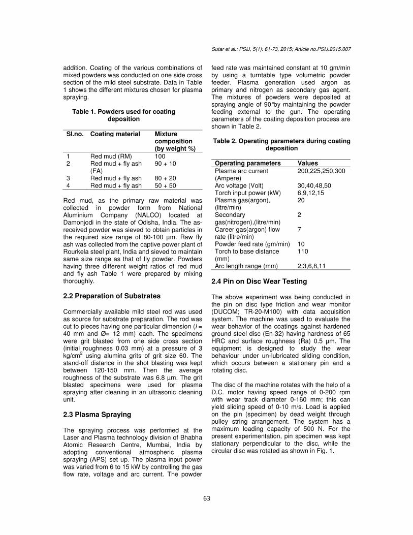
2.4 Pin on Disc Wear Testing The above experiment was being conducted in the pin on disc type friction and wear monitor (DUCOM; TR-20-M100) with data acquisition system. The machine was used to evaluate the wear behavior of the coatings against hardened ground steel disc (En-32) having hardness of 65 HRC and surface roughness (Ra) 0.5 µm. The equipment is designed to study the wear behaviour under un-lubricated sliding condition, which occurs between a stationary pin and a rotating disc. The disc of the machine rotates with the help of a D.C. motor having speed range of 0-200 rpm with wear track diameter 0-160 mm; this can yield sliding speed of 0-10 m/s. Load is applied on the pin (specimen) by dead weight through pulley string arrangement. The system has a maximum loading capacity of 500 N. For the present experimentation, pin specimen was kept stationary perpendicular to the disc, while the circular disc was rotated as shown in Fig. 1.
Sutar et al.; PSIJ, 5(1): 61-73, 2015; Article no.PSIJ.2015.007
64
Fig. 1. Schematic representation of pin on disc apparatus
3. RESULTS AND DISCUSSION 3.1 Scanning Electron Microscopy and
Compositional Analysis The characterization of red mud powder involved taking microstructures by the help of scanning electron microscope (JEOL; JSM-6480 LV). The micro structural images captured by SEM (scanning electron microscope) and EDS (energy dispersive spectroscopy) analysis of pure red mud powder are illustrated in Fig. 2. EDS experiment was performed by the above SEM with the required attached module. Data presented in Table 3 indicates the weight as well the atomic percentage of elements comprising pure red mud powder. The EDS analysis of red mud revealed the signature of elements like Fe,
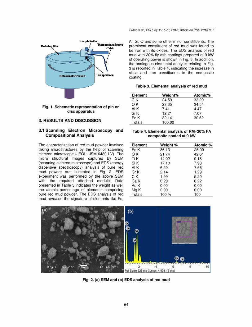
Al, Si, O and some other minor constituents. The prominent constituent of red mud was found to be iron with its oxides. The EDS analysis of red mud with 20% fly ash coatings prepared at 9 kW of operating power is shown in Fig. 3. In addition, the analogous elemental analysis relating to Fig. 3 is reported in Table 4, indicating the increase in silica and iron constituents in the composite coating.
Table 3. Elemental analysis of red mud
Element Weight% Atomic%
C K 24.59 33.29 O K 23.65 24.54 Al K 7.41 4.47 Si K 12.21 7.07 Fe K 32.14 30.62 Totals 100.00
Table 4. Elemental analysis of RM+20% FA
composite coated at 9 kW
Element Weight % Atomic %
Fe K 36.13 25.90 O K 21.74 42.61 Ti K 14.02 9.18 Si K 17.10 7.93 Al K 6.59 7.66 Cr K 2.14 1.29 C K 1.99 5.20 Ca K 0.29 0.22 Au K 0.00 0.00 Mg K 0.00 0.00 Totals 100 % 100
Fig. 2. (a) SEM and (b) EDS analysis of red mud
Sutar et al.; PSIJ, 5(1): 61-73, 2015; Article no.PSIJ.2015.007
65
3.2 Coating Porosity Image analysis technique was adopted for the measurement of porosity of coating materials. The polished surfaces of various coatings were kept under a microscope (Neomate) equipped with a charge coupled-device (CCD) camera (JVC, TK 870E). Volume of interest (VOIS) image analysis software paid an important role for the determination of porosity. The software can measure accurately the total area captured by the objective of the microscope. Hence the
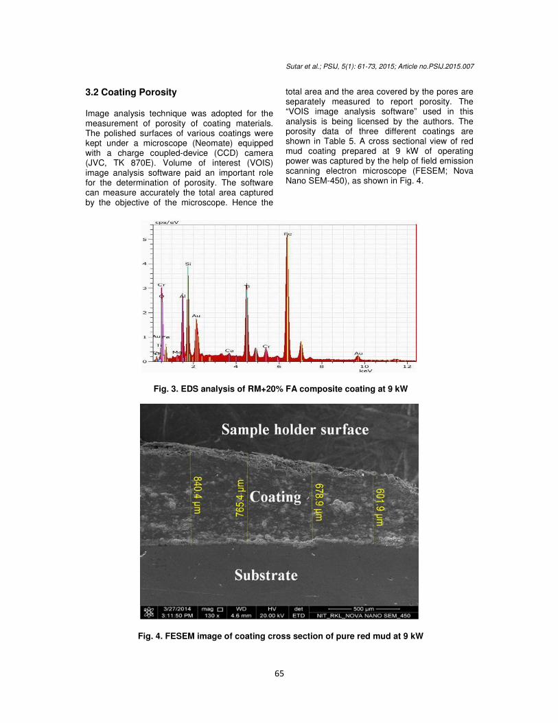
total area and the area covered by the pores are separately measured to report porosity. The “VOIS image analysis software” used in this analysis is being licensed by the authors. The porosity data of three different coatings are shown in Table 5. A cross sectional view of red mud coating prepared at 9 kW of operating power was captured by the help of field emission scanning electron microscope (FESEM; Nova Nano SEM-450), as shown in Fig. 4.
Fig. 3. EDS analysis of RM+20% FA composite coating at 9 kW
Fig. 4. FESEM image of coating cross section of pure red mud at 9 kW

Sutar et al.; PSIJ, 5(1): 61-73, 2015; Article no.PSIJ.2015.007
66
Table 5. Coating porosity for different coating type
Coating material
Plasma torch input power(kW)
Porosity (%)
Red mud 6 12.89 9 12.02 12 11.87 15 13.02
90% red mud +10% fly ash
6 11.52 9 11.12 12 10.90 15 12.98
80% red mud +20% fly ash
6 10.89 9 10.54 12 10.17 15 11.78
Approximately 8-13% porosity range was observed Table 5 for all three coating materials. Porosity amount was found to be ameliorated in case of all coating compositions prepared at lower (6 kW) and at higher (15 kW) power levels. At 6 kW operating power level, there is poor melting of particles subjected to relatively low plasma gas temperature exhibiting non-uniform mixing of molten particles; which in turn causes reasonably porous coating layer. On the other hand, at highest operating power level (15 kW) the high plasma gas temperature caused faster deposition of molten particles by creating thickened coating layer with less hardness and high porosity. Porosity level was found to be higher in case of pure red mud compared to the composite coatings made of the mixture of fly ash and red mud. About 3-10% porosity level was reported for the coatings prepared by conventional plasma spraying [18], which supports the porosity results obtained in the present investigation.
3.3 Coating Hardness The polished section of the coatings put under optical microscope for the microscopic observations, which revealed the presence of three distinguishable different phases namely dull, white and spotted. The three different distinct phases were subject to micro indenting to record micro hardness data with the help of Leitz micro hardness tester using 50 Pa (0.493 N) on all samples. The results are summarized in Table 6. The three structurally different phases of
red mud coatings bear three different ranges of hardness values varying from 488 to 588 HV. Hardness values were found to be enhanced for the red mud and fly ash composite coatings. This result is attributed to the increased content of alumina and silica in the composition of feed material forming alumino-silicate (mullite phase) during spray deposition [19].
Table 6. Coating hardness for different operating power level
Coating material
Plasma torch input power ( kW)
Micro hardness (HV)
Dull White Spotted
100% red mud
6 540 488 496 9 532 498 511 12 586 513 508 15 555 502 510
90% red mud +10% fly ash
6 638 632 628 9 648 642 636 12 660 638 628 15 651 640 632
80% red mud +20% fly ash
6 658 649 642 9 669 658 649 12 699 689 652 15 681 681 650
50% red mud +50% fly ash
6 696 679 658 9 682 633 672 12 726 712 660 15 719 679 668
3.4 Wear Test Study Prior to starting the wear testing experiment, the pin and the disc surface of the concerned equipment were polished perfectly with emery papers for better ensuring of smooth contact with the coating samples. Hereafter the surface roughness was reduced to 0.1 µm. The wear tests were carried out per ASTM G- 99 standard for maximum time period of 30 minutes under un-lubricated condition in a normal laboratory ambience having relative humidity of 40-55% and the temperature range of 20-25°C. The weight of the specimens before and after the wear experiment being recorded by using electronic weighing machine having accuracy of (0.01 mg) for monitoring the mass loss occurrence in the coating samples. Specimens were periodically cleaned with woolen cloth to avoid entrapment of wear debris and to maintain uniformity in each set of experiments. The test pieces were cleaned with tetrachloroethylene solution before and after
Sutar et al.; PSIJ, 5(1): 61-73, 2015; Article no.PSIJ.2015.007
67
each test. Wear rate was estimated by measuring the mass loss (∆m) of the specimen after each test. Wear rate relating to mass loss and the sliding distance (L) was formulated below in equation (1).
L
mW
r
∆=
(1)
Where
rW
= wear rate in N/m;
m∆ = mass Loss in Newton (N);
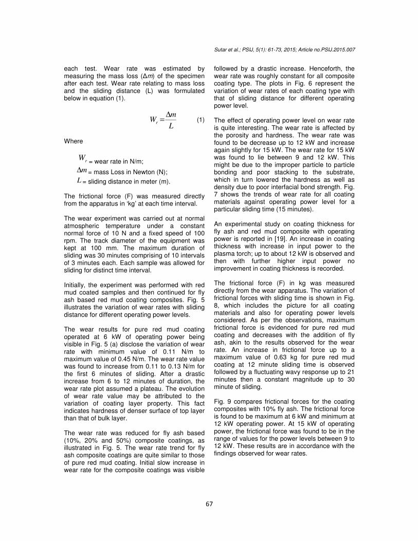
L = sliding distance in meter (m). The frictional force (F) was measured directly from the apparatus in ‘kg’ at each time interval. The wear experiment was carried out at normal atmospheric temperature under a constant normal force of 10 N and a fixed speed of 100 rpm. The track diameter of the equipment was kept at 100 mm. The maximum duration of sliding was 30 minutes comprising of 10 intervals of 3 minutes each. Each sample was allowed for sliding for distinct time interval. Initially, the experiment was performed with red mud coated samples and then continued for fly ash based red mud coating composites. Fig. 5 illustrates the variation of wear rates with sliding distance for different operating power levels. The wear results for pure red mud coating operated at 6 kW of operating power being visible in Fig. 5 (a) disclose the variation of wear rate with minimum value of 0.11 N/m to maximum value of 0.45 N/m. The wear rate value was found to increase from 0.11 to 0.13 N/m for the first 6 minutes of sliding. After a drastic increase from 6 to 12 minutes of duration, the wear rate plot assumed a plateau. The evolution of wear rate value may be attributed to the variation of coating layer property. This fact indicates hardness of denser surface of top layer than that of bulk layer. The wear rate was reduced for fly ash based (10%, 20% and 50%) composite coatings, as illustrated in Fig. 5. The wear rate trend for fly ash composite coatings are quite similar to those of pure red mud coating. Initial slow increase in wear rate for the composite coatings was visible
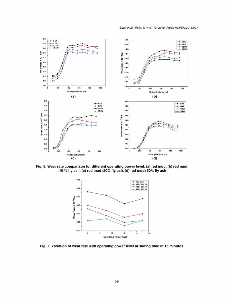
followed by a drastic increase. Henceforth, the wear rate was roughly constant for all composite coating type. The plots in Fig. 6 represent the variation of wear rates of each coating type with that of sliding distance for different operating power level. The effect of operating power level on wear rate is quite interesting. The wear rate is affected by the porosity and hardness. The wear rate was found to be decrease up to 12 kW and increase again slightly for 15 kW. The wear rate for 15 kW was found to lie between 9 and 12 kW. This might be due to the improper particle to particle bonding and poor stacking to the substrate, which in turn lowered the hardness as well as density due to poor interfacial bond strength. Fig. 7 shows the trends of wear rate for all coating materials against operating power level for a particular sliding time (15 minutes). An experimental study on coating thickness for fly ash and red mud composite with operating power is reported in [19]. An increase in coating thickness with increase in input power to the plasma torch; up to about 12 kW is observed and then with further higher input power no improvement in coating thickness is recorded. The frictional force (F) in kg was measured directly from the wear apparatus. The variation of frictional forces with sliding time is shown in Fig. 8, which includes the picture for all coating materials and also for operating power levels considered. As per the observations, maximum frictional force is evidenced for pure red mud coating and decreases with the addition of fly ash, akin to the results observed for the wear rate. An increase in frictional force up to a maximum value of 0.63 kg for pure red mud coating at 12 minute sliding time is observed followed by a fluctuating wavy response up to 21 minutes then a constant magnitude up to 30 minute of sliding. Fig. 9 compares frictional forces for the coating composites with 10% fly ash. The frictional force is found to be maximum at 6 kW and minimum at 12 kW operating power. At 15 kW of operating power, the frictional force was found to be in the range of values for the power levels between 9 to 12 kW. These results are in accordance with the findings observed for wear rates.

Sutar et al.; PSIJ, 5(1): 61-73, 2015; Article no.PSIJ.2015.007
68
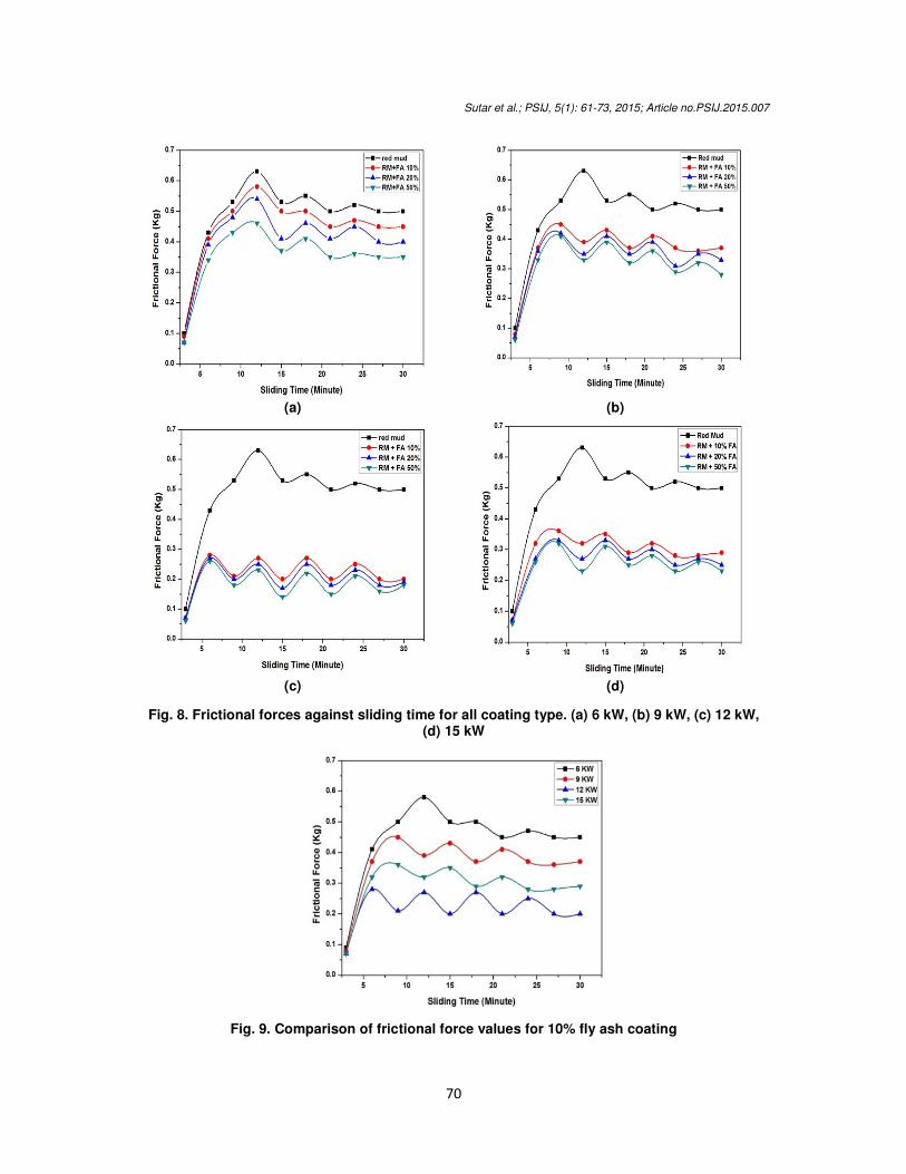
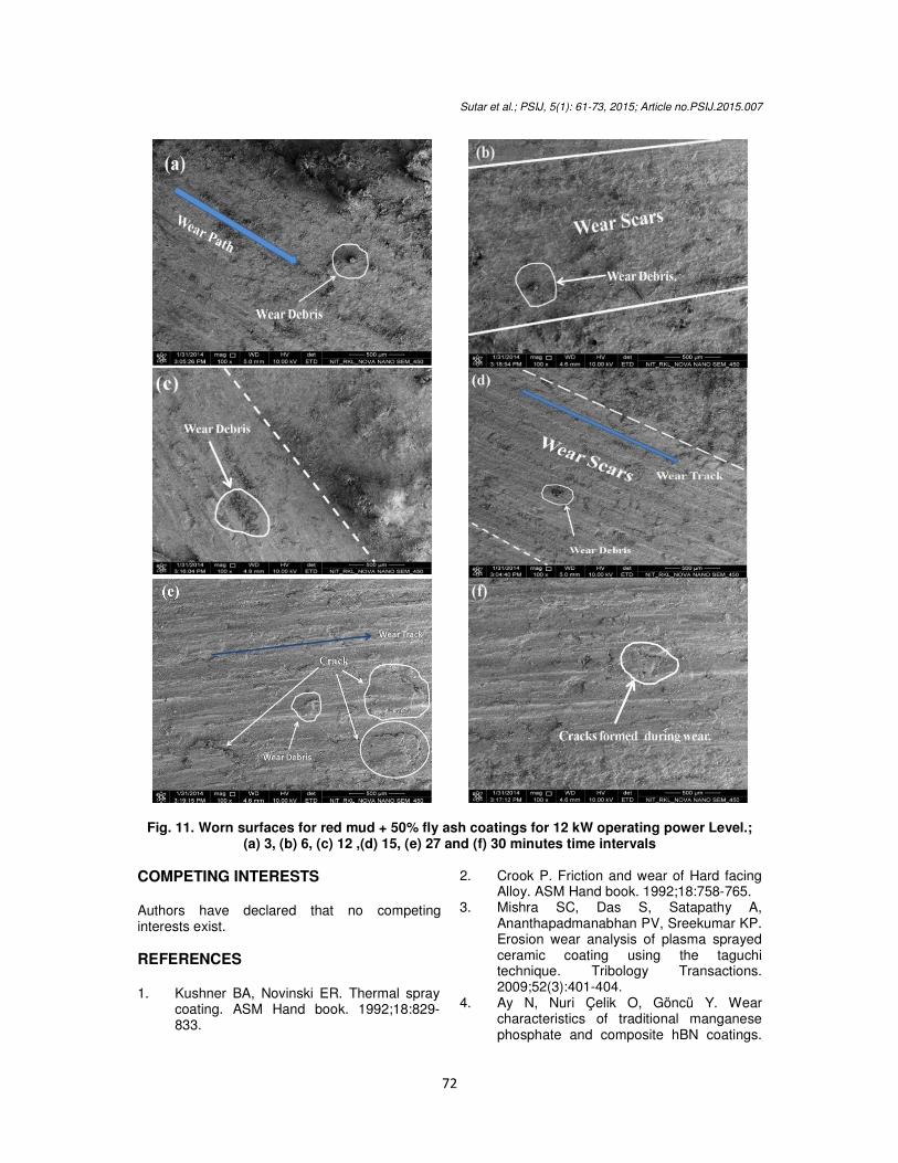
Wear morphology for selected coating samples are highlighted in some images captured by FESEM. Fig. 10 represents the wear morphological images for red mud with 10% fly ash coating (prepared at 6 kW operating power) allowed for sliding for the time intervals of 3, 6, 12 and 15 minutes. Owing to continuous sliding of counter surfaces, wear debris formed which interlock within the sliding interfaces, causing pitting and eventually crack formation. Wear scars, debris formed and cracked sections are clearly visible in Fig. 10 (b) and (d) indicating a fatigue failure on the worn surface. Fig. 11 shows the worn surfaces for 50% fly ash based red mud coatings (prepared at 12 kW of operating power level) for the sliding intervals 3, 6, 12, 15, 27 and 30 minutes. The wear morphology changes with increase in the sliding distance impacting change in surface roughness leading to the interruption
of its contact mechanism. The change in wear characteristics may be attributed to the variation of hardness of coating inter-layers with respect to the change in sliding distance. At incipient, a slow increase in wear rate is observed and then attains a rapid increment, the ‘break in’ situation, after traversing of certain sliding distance. The further increase in sliding distance cannot change the contact area; causing a relatively steady wear rate. Hence, it can be concluded that the wear takes place by the phenomenon of adhesion and abrasive mechanism due to development of shear stresses between the hard asperities of the two surfaces in contact. After the “break in” phase, the trend of wear rate remains almost constant for coatings deposited at all power levels. The duration of this stage extends till the end of the test.
(a) (b)
(c) (d)
Fig. 5. Wear rates obtained for different coating type with sliding distance. (a) 6 kW, (b) 9 kW,
(c) 12 kW, (d) 15 kW
Sutar et al.; PSIJ, 5(1): 61-73, 2015; Article no.PSIJ.2015.007
69
(a) (b)
(c) (d)
Fig. 6. Wear rate comparison for different operating power level. (a) red mud, (b) red mud
+10 % fly ash, (c) red mud+20% fly ash, (d) red mud+50% fly ash
Fig. 7. Variation of wear rate with operating power level at sliding time of 15 minutes
Sutar et al.; PSIJ, 5(1): 61-73, 2015; Article no.PSIJ.2015.007
70
(a) (b)
(c) (d)
Fig. 8. Frictional forces against sliding time for all coating type. (a) 6 kW, (b) 9 kW, (c) 12 kW, (d) 15 kW
Fig. 9. Comparison of frictional force values for 10% fly ash coating
Sutar et al.; PSIJ, 5(1): 61-73, 2015; Article no.PSIJ.2015.007
71
Fig. 10. Worn surfaces for red mud + 10% fly ash coatings for 6 kW operating power level.; (a) 3, (b) 6, (c) 12 and (d) 15 minutes time interval
4. CONCLUSION The present allow for some salient concluding remarks. Red mud, the waste generated from alumina plants is coat able on metal substrates by employing thermal plasma spraying technique with excellent wear resistance. The addition of fly ash with red mud reduces the wear rate by enhancing the coating property. But the optimum percentages of fly ash required for better coating material still impact a question mark for the researchers. It is observed that for the early stage the wear rate increases slowly and then rises drastically with sliding distance for all coating type and finally becomes stagnant. Operating power level proved to be the
remarkable variable for coating property. The coating wear resistance increases until an optimum value at 12 kW indicating some other dominating parameters. The present work leaves a wide spectrum of scopes for future investigators to explore many other aspects of red mud coatings. Thermal stability of these coatings may be evaluated for better claiming in high temperature applications. Corrosive wear behavior under different operating conditions may be investigated to identify suitable application areas. Post heat treatment of these coatings may also be implemented for furthering the study regarding the improvement in coating quality and properties.
Sutar et al.; PSIJ, 5(1): 61-73, 2015; Article no.PSIJ.2015.007
72
Fig. 11. Worn surfaces for red mud + 50% fly ash coatings for 12 kW operating power Level.;
(a) 3, (b) 6, (c) 12 ,(d) 15, (e) 27 and (f) 30 minutes time intervals
COMPETING INTERESTS Authors have declared that no competing interests exist.
REFERENCES 1. Kushner BA, Novinski ER. Thermal spray
coating. ASM Hand book. 1992;18:829-833.
2. Crook P. Friction and wear of Hard facing Alloy. ASM Hand book. 1992;18:758-765.
3. Mishra SC, Das S, Satapathy A, Ananthapadmanabhan PV, Sreekumar KP. Erosion wear analysis of plasma sprayed ceramic coating using the taguchi technique. Tribology Transactions. 2009;52(3):401-404.
4. Ay N, Nuri Çelik O, Göncü Y. Wear characteristics of traditional manganese phosphate and composite hBN coatings.
Sutar et al.; PSIJ, 5(1): 61-73, 2015; Article no.PSIJ.2015.007
73
Tribology Transactions. 2013;56(6):1109-1118.
5. Afzal M, Ajmal M, Khan AN. Wear behavior of WC-12% Co coatings produced by air plasma spraying at different standoff distances. Tribology Transactions. 2014;57(1):94-103.
6. Wayne SF, Sampath S, Anand V. Wear mechanisms in thermally sprayed mo-based coatings. Tribology Transactions. 1994;37(3):636-640.
7. Wang Y, Jin Y, Wen S. The analysis of the friction and wear mechanisms of plasma-sprayed coatings at 450°C. Wear. 1998;128:265–276.
8. Wang Y, Jin Y, Wen S. The analysis of the chemical structure and properties of ceramic surface films in friction using SEM, AES and Micro-region X-ray diffraction. Wear. 1998;128:277–290.
9. Wang Y, Jin Y, Wen S. The inspection of sliding surface and subsurface of plasma-sprayed using scanning acoustic microscopy. Wear. 1998;134:399–411.
10. Vijande-Diaz R, Belzunce J, Fernandez E, Rincon A, Pérez MC. Wear and microstructure in fine ceramic coatings. Wear. 1991;148:233–331.
11. Wei J, Xue Q. Effects of additives on friction and wear behaviour of Cr2O3 coatings. Wear. 1993;160:61–65.
12. Homberg K, Mathews A, Ronkainen H. Coatings tribology-contact mechanisms and surface design. Tribology International. 1998;31(1-3):107-120.
13. Sutar H, Mishra SC, Sahoo SK, Chakraverty AP, Maharana HS. Progress of red mud utilization: An overview. American Chemical Science Journal. 2014;4(3):255-279.
14. Sutar H, Mishra SC, Sahoo SK, Satapathy A, Kumar V. Morphology and solid particle erosion wear behaviour of red mud composite coatings. Natural Science. 2012;4(11):832-838.
15. Satapathy A, Sutar H, Mishra SC, Sahoo SK. Characterization of plasma sprayed pure red mud coatings: An analysis. American Chemical Science Journal. 2013;3(2):151-163.
16. Prasad N, Sutar H, Mishra SC, Sahoo SK, Acharya SK. Dry sliding wear behavior of aluminium matrix composite using red mud an industrial waste. International Research Journal of Pure and Applied Chemistry. 2013;3(1):59-74.
17. Sutar H, Mishra SC, Sahoo SK, Maharana HS, Chakraverty AP. Tribological aspects of thermally sprayed red mud-fly ash and red mud-Al coatings on mild steel. American Chemical Science Journal. 2014;4(6):1014-1031.
18. Pawlowski L. The science and engineering of thermal spray coatings. John Wiley and Sons, New York. 1995;218.
19. Satapathy A. Thermal spray coating of red mud on metals, PhD Thesis, National Institute of Technology, Rourkela, Odisha, India; 2005.
_________________________________________________________________________________ © 2015 Sutar et al.; This is an Open Access article distributed under the terms of the Creative Commons Attribution License (http://creativecommons.org/licenses/by/4.0), which permits unrestricted use, distribution, and reproduction in any medium, provided the original work is properly cited.
Peer-review history: The peer review history for this paper can be accessed here:
http://www.sciencedomain.org/review-history.php?iid=679&id=33&aid=6532