frequency dependent impedance analysis of the …
TRANSCRIPT

FREQUENCY DEPENDENT IMPEDANCE ANALYSIS OF THE
FOUNDATION-SOIL-SYSTEMS OF ONSHORE WIND TURBINES
Philipp MICHEL1, Christoph BUTENWEG
2, Sven KLINKEL
3
ABSTRACT
Due to the growing use of wind energy, wind turbines need to be built on sites with poor load bearing character.
To increase stability und durability of the turbines, dynamic investigation of the holistic system consisting of
turbine, tower and foundation, including soil-structure-interaction (SSI) effects need to be carried out. The use of
different foundations, shallow or pile foundations, on varying soil conditions affects the overall dynamic
behavior of the slender wind turbine tower. Therefore, a frequency tuning might be necessary while designing
the tower. The influence of the SSI effects on slender structures is well known in research and practice.
However, the choice of adequate and problem oriented SSI calculation belongs to the experience of the structural
engineer. The available methods vary from simple analytical models to highly sophisticated numerical methods,
demanding high calculation costs. This study attempts to streamline this selection process, presenting an
impedance catalogue for an onshore wind turbine, to be used by practical engineers to estimate the dynamic
impedance and the vibration behavior of the system in few steps. Frequency dependent impedance functions are
presented for shallow and pile foundations on homogenous and layered soils. These functions are computed
using the substructure method, dividing the overall system into structure and soil model. While the structure of
the wind turbine is modelled via the finite element method, the soil model is constructed using the boundary
element method. Concluding the holistic model is exposed to wind load to examine the SSI influence during
dynamic loading.
Keywords: soil-structure-interaction, soil dynamics, vibration analysis, onshore wind turbines
1. INTRODUCTION
1.1 Motivation
Soil-structure-interaction (SSI) effects play an important role in the design of wind turbines, both
offshore and onshore. The established design codes cover this field and demand SSI analyses, as the
design of the wind turbine is heavily frequency dependent. In a current scientific project at RWTH
Aachen University, a joint team of mechanical engineers and structural engineers from the fields of
steel construction and structural dynamics investigate the overall wind turbine behaviour to improve
the holistic system. Aim of the project is to minimize friction at the discipline-specific interfaces while
simulating the soil-structure-drive-train interaction. In this project a reference onshore wind turbine is
created which is used to carry out all simulations. This investigation focuses on the SSI part of the
project.
As holistic simulations of SSI investigations are time consuming and costly, the practical engineer has
to use simplifying methods. One approach is to apply the substructure method were the overall system
is divided into subsystems. The current paper follows this approach, with the focus on the foundation-
soil system. Impedance functions for different foundations-soil models are computed in advance and
1Research Assistant, Chair of Structural Analysis and Dynamics, Aachen, Germany, [email protected]
2Professor, Center for Wind and Earthquake Engineering, Aachen, Germany, [email protected]
3Professor, Chair of Structural Analysis and Dynamics, Aachen, Germany, [email protected]

2
are coupled with the structure of a wind turbine in the second step. This procedure allows to carry out
the complex SSI calculation in advance giving the possibility to study the SSI effects of the soil at a
certain site. The wind turbine model can be modelled using highly sophisticated FE tools. Once a
database of impedance functions for various soil models is created, this catalogue can be used for
multiple wind turbine simulations.
1.2 State of the Art
Early SSI studies investigate vibrating machines on elastic half-space (Gazetas, 1983). Especially the
response of tall and slender structures is altered by the presence of compliant soil (Luco, 1986). A
milestone in analyzing the foundation-soil-behavior was the introduction of the term of the dynamic
impedance function of the system (Lysmer, 1965). Kausel (2010) clearly shows the evolution of SSI
computations; the next important milestone was the usage of numerical approaches, allowing the
investigation of more complex systems with layered soils and deep foundations. The substructure
method is a possible approach, where the structure and the soil are decoupled and determined
separately. For the holistic investigation the sub-systems are coupled again. For example, the structure
is modelled using the Finite Element Method (FEM) and the soil is modelled using approaches such as
the Boundary Element Method (BEM). FEM-BEM coupling allows the consideration of complex soil
composition as well as detailed structure modelling (Savidis et al., 2002). Taddei et al. (2014) study
the SSI effects on a wind turbine based on a shallow foundation on layered soil using FEM-BEM
coupling. The results are in alignment with other investigations concerning the influence of SSI on
wind turbines. Bazeos et al. (2002) describe the alternation of the eigenfrequency of turbines resting
on compliant soil. The findings of Zhao and Maisser (2006) confirm the influence of the SSI on the
natural frequency of the turbine. Andersen (2010) applies lumped parameter models to show, that
especially the higher modes of the turbine tower are damped due to the energy transmission into the
ground. A simplified cone model is used by Harte et al. (2012), who show the alteration of the
response in the time domain by compliant soil. The influence of layered soil on the turbine is studied
in Taddei et al. (2014), which underlines the importance of the influence of the relative stiffness of
structure and soil and the stiffness ratio of different soil layers. Kaynia (1982) and Garcia (2002) carry
out research on the dynamic interaction of piles and soil. Pile foundations of wind turbines are in the
focus of Zania (2014), who investigates the influence of the dynamic soil-pile interaction on the
natural frequencies and the damping of offshore wind turbines. Present research on multi pile groups is
carried out by Medina et al. (2014) who use FEM-BEM coupling to investigate the impact of pile
inclination on the response of pile groups.
1.3 Goals and Outline
Impedance functions are calculated and presented for different soil models in the frequency domain
using a reliable FEM-BEM code. The soil models vary from homogenous soil to multi layered soil,
both shallow and pile foundations are investigated. The influence of the soil properties on the
impedance functions are observed and discussed. Afterwards the impedance functions are coupled to
the simplified model of a 3.2 MW onshore wind turbine model which is created in ANSYS. First it is
investigated how the response of the holistic is influenced by SSI effects and how this behavior
resembles the behavior of the foundation-soil substructure. Afterwards the response of the wind
turbine under wind load on compliant soil is investigated in the frequency domain.
2. DYNAMIC IMPEDANCE
2.1 Soil-Structure-Interaction
The equation of motion for a structure is
(1)
3
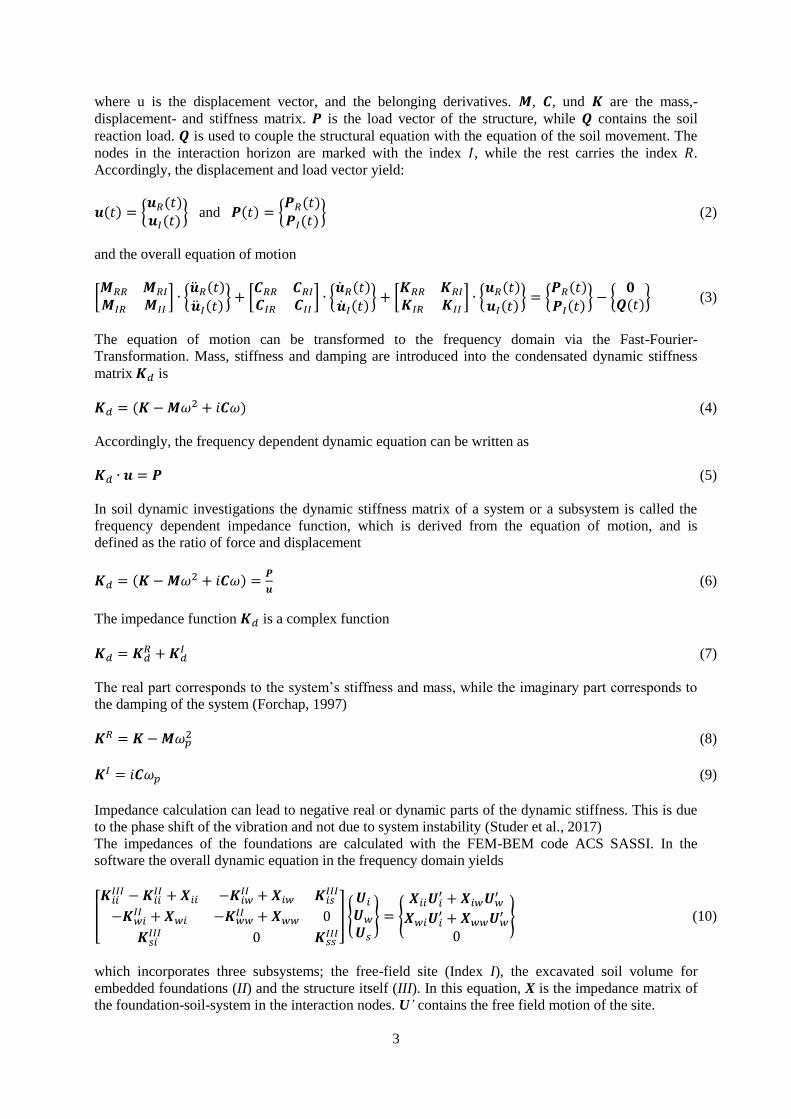
where u is the displacement vector, and the belonging derivatives. , , und are the mass,-
displacement- and stiffness matrix. is the load vector of the structure, while contains the soil
reaction load. is used to couple the structural equation with the equation of the soil movement. The
nodes in the interaction horizon are marked with the index , while the rest carries the index .
Accordingly, the displacement and load vector yield:
and
(2)
and the overall equation of motion
(3)
The equation of motion can be transformed to the frequency domain via the Fast-Fourier-
Transformation. Mass, stiffness and damping are introduced into the condensated dynamic stiffness
matrix is
(4)
Accordingly, the frequency dependent dynamic equation can be written as
(5)
In soil dynamic investigations the dynamic stiffness matrix of a system or a subsystem is called the
frequency dependent impedance function, which is derived from the equation of motion, and is
defined as the ratio of force and displacement
(6)
The impedance function is a complex function
(7)
The real part corresponds to the system’s stiffness and mass, while the imaginary part corresponds to
the damping of the system (Forchap, 1997)
(8)
(9)
Impedance calculation can lead to negative real or dynamic parts of the dynamic stiffness. This is due
to the phase shift of the vibration and not due to system instability (Studer et al., 2017)
The impedances of the foundations are calculated with the FEM-BEM code ACS SASSI. In the
software the overall dynamic equation in the frequency domain yields
(10)
which incorporates three subsystems; the free-field site (Index I), the excavated soil volume for
embedded foundations (II) and the structure itself (III). In this equation, X is the impedance matrix of
the foundation-soil-system in the interaction nodes. U’ contains the free field motion of the site.

4
To calculate the soil stiffness, Green’s functions must be computed for the elastodynamic soil system,
which is done using the Thin-Layer-Method (TLM) (Kausel, 1981). The Green’s functions describe
the soil flexibility, hence the relationship between a load at one point of the soil and the displacement
at another point of the soil. The flexibility is the inverse of the stiffness of the soil. These fundamental
solutions have to consider certain boundary conditions such as a free surface at the top and bottom
boundary conditions, which are dependent on the natural soil configuration. They are able to consider
a homogenous half space, a layered half space and soil layers over a bedrock. The assumption of a free
surface and steadfast bedrock at the bottom provides the boundary conditions of no stress at the top
and no displacements at the bottom of the model. The TLM divides the soil in multiple thin layers to
calculate the relationship of a concentrated load and the displacement in one thin layer. Subsequently
the stiffness matrices of each thin layer are overlapped to obtain the relationship for the complete soil
model.
2.2 Validation
Before the actual investigation, the applied methods are validated. Focus is put on the impedance of
the pile foundation, the systems with the higher complexity. Therefore, the dynamic impedance
functions for a rectangular foundation with a 2x2 pile group are calculated and compared to results
from the literature (Garcia, 2002). In this example, the rigid foundation has no contact to the soil. The
ratio of the center to center distance of the piles and the pile diameter is , with , and a pile diameter of 0.2 m. The foundation is resting on a homogenous soil, with an underlying
homogenous half-space. Both are considered soft with an ratio of
for the Young’s
Moduli. The soil parameters are equal for layer and half-space, additional soil and pile parameters can
be found in Table 1. Figure 1 shows the real and the imaginary part of the impedance functions in
vertical and horizontal direction. The complex impedance values of a pile group (index ) are
normalized with the static stiffness of a single pile (index ), multiplied with the number of used piles.
is the dimensionless frequency depending on the circular frequency of the harmonic vibration ,
the pile diameter and the shear wave velocity of the soil
(11)
A good agreement can be seen for the dynamic stiffness of the piles in both directions. These
differences are to believed due to the employed computational methods. In general, the dynamic
stiffness of the monopile shows very little frequency dependence. The present 2x2 pile group shows a
strong frequency dependence in both the real and the imaginary component.
Table 1: Properties of the soil and pile model used in the validation.
System [MN/m²]
[kg/m³] [-] [m/s] [-] [m] [m]
Soil 332.5 2000 0.40 250 0.05 - -
Pile 332.5 x 10³ 2857 0.25 - 0.00 9 0.2

5
Figure 1. Dynamic impedance function in horizontal and vertical direction of a 2x2 pile group.
(a) contains the real part, (b) the imaginary part.
2.3 Modelling
The model of the foundation and the pile structure are created based on the results of the pre-design of
the foundations of the reference turbine. The foundation has a radius of 11 m, and is simplified to a
disk with a height of 1.6 m. The pile foundation incorporates 48 piles with a length of 30 m, which are
distributed periodically around the circular foundation. The piles are divided into an inner pile group
inclined with 6° and an outer group inclined with 10° in the opposite direction (
Figure 2). Both foundations are described in Σφάλμα! Το αρχείο προέλευσης της αναφοράς δεν
βρέθηκε., which shows relevant information on the disk and the piles. The mass of the disk is 1520
tons, the overall mass of disk and all piles is 5728 tons.
Table 2: Properties of the disk and the piles of the foundations used in the dynamic investigations.
Radius
[m]
Height
[m]
Density
[t/m³]
Pile
Diameter[m]
Number
of piles
Pile length
[m]
Damping
[-]
11 1.6 2.5 0.61 48 30 0.05
Figure 2. Geometry of the shallow and pile foundations.
While the foundation is created using solid elements, the piles are represented by beam elements. The
beams are connected to the solids in multiple nodes to couple displacement and rotational degrees of
freedom of the beam with the three displacement degrees of freedom of the solid element. The piles
are divided in 24 parts with an element length of lc = 1.25 m. The interaction nodes have to be located
0
0.5
1
1.5
2
2.5
3
0 0.25 0.5 0.75 1
kii
,G /
(n∙k
0ii
,s)
a0
( a )
horizontal vertical
[Garcia, 2002]
0
2
4
6
8
10
12
0 0.25 0.5 0.75 1
c ii,
G /
(n∙c
0ii
,s)
a0
( b )
[Garcia, 2002] horizontal
vertical
R = 11.00 (foundation bottom edge) R = 10.40 (radius of outer pile row)
R = 9.80 (radius of outer pile row) R = 5.00 (foundation top edge)
+ 1.75 top edge
-1.35 bottom edge
0.0 ground surface
outer piles inner piles
10° 6° 10° 6°

6
on the boundaries of the soil layers defined by the thin-layer-method. The application of the TLM
(Kausel, 1981) has to follow certain conditions such as the thickness of the thin layers and the element
size in the interaction horizon. The thickness of a thin layer is obtained via
(12)
Where the wave length λ is the ratio of the minimum shear wave velocity νs of all the physical layers
and the maximum investigated frequency fmax:
(13)
The element size in the interaction horizon also needs to be in relation to the shear wave velocity of
the top layer and the frequency to enable accurate computation. The maximum element size equals the
layer thickness
. The minimum shear wave velocity in this analysis will be 100 m/s, the
maximum investigation frequency is 25 Hz. Hence the maximum soil layer thickness results to 0.8 m.
The layer thickness is chosen equal to 0.625 m satisfying both conditions. The same rules apply for the
element sizes in the foundation, so the maximum element edge length is 0.625 m. The mesh of the
surface foundation is shown in
Figure 3. Both the surface nodes of the foundation model and the nodes of the piles are fully coupled
with the soil.
Figure 3. (left) Element size in the foundation mesh. (right) Tower model on a multi pile grid on the
layered soil model The investigation point A is located at the tower top mass, point B is placed on the
top of the stiff bedrock, point C at the foundation top.
2.4 Impedance Functions
The impedance functions for both foundation types are dependent on the frequency and on the soil
properties like shear modulus, density and layering. Impedances for six degrees of freedom are
obtained, horizontal, vertical motion, rocking and torsion in the frequency domain. With the wind
turbine foundations being rotationally symmetric, the impedances in the both horizontal direction and
the rocking impedances are equal.
B
C
A x
z
7
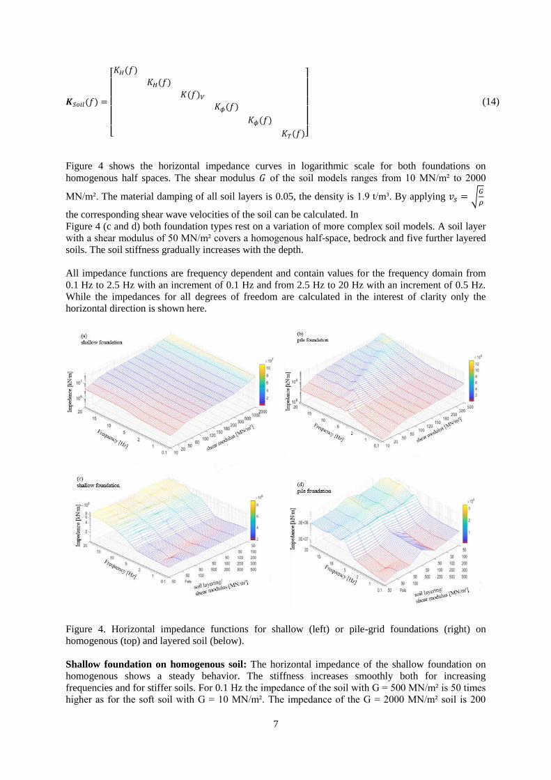
(14)
Figure 4 shows the horizontal impedance curves in logarithmic scale for both foundations on
homogenous half spaces. The shear modulus of the soil models ranges from 10 MN/m² to 2000
MN/m². The material damping of all soil layers is 0.05, the density is 1.9 t/m³. By applying
the corresponding shear wave velocities of the soil can be calculated. In
Figure 4 (c and d) both foundation types rest on a variation of more complex soil models. A soil layer
with a shear modulus of 50 MN/m² covers a homogenous half-space, bedrock and five further layered
soils. The soil stiffness gradually increases with the depth.
All impedance functions are frequency dependent and contain values for the frequency domain from
0.1 Hz to 2.5 Hz with an increment of 0.1 Hz and from 2.5 Hz to 20 Hz with an increment of 0.5 Hz.
While the impedances for all degrees of freedom are calculated in the interest of clarity only the
horizontal direction is shown here.
Figure 4. Horizontal impedance functions for shallow (left) or pile-grid foundations (right) on
homogenous (top) and layered soil (below).
Shallow foundation on homogenous soil: The horizontal impedance of the shallow foundation on
homogenous shows a steady behavior. The stiffness increases smoothly both for increasing
frequencies and for stiffer soils. For 0.1 Hz the impedance of the soil with G = 500 MN/m² is 50 times
higher as for the soft soil with G = 10 MN/m². The impedance of the G = 2000 MN/m² soil is 200

8
times higher than for the weak soil and shows rock-like behavior. This includes just a small increase of
stiffness for the higher frequencies. The frequency influence is higher for the weaker soils, where the
impedance curve shows a slight s-form. This includes a rise in stiffness in the range of 5 Hz. The
dynamic stiffness in vertical direction is larger than in horizontal direction and the increase of stiffness
is more abrupt. However, the qualitative process of the impedance is the same, which can also be said
about the rocking and torsion impedance.
Pile foundation on homogenous soil: The horizontal impedance of the pile-grid on homogenous soil
also increases with increasing shear modulus and increasing frequency. However, the general progress
is less smooth, showing a clear eigenfrequency-peak. This peak moves in higher frequency ranges for
soils with increasing stiffness. Again, a more or less abrupt rise of impedance can be seen in the 5 Hz
range. This rise is most significant for soils with a medium stiffness. After the local peak, the
impedances decrease again. This proofs the dynamic behavior of the system, which shows a
significant eigenfrequency in this range. The qualitative progress of vertical, rocking and torsional
impedance is the same. In general, the pile-grid foundation has a much larger stiffness as the shallow
foundation and is more frequency dependent.
Shallow foundation on layered soil: The tendency of the increasing impedance with higher
frequency and soil stiffness stays the same. However, the system shows more complex behavior with
multiple local maxima and minima. The frequency increase in the 5 Hz range is more abrupt than for
the homogenous half space.
Pile foundation on layered soil: The general tendency in the influence of frequency and soil stiffness
stays the same. However, the curves show more maxima and minima. Significant is the maximum in
the 5 Hz region for all models. The influence of the stiff section in the multi-layer soil is clearly
visible, a G = 500 MN/m² soil under a softer G = 10 MN/m² layer increases the overall impedance.
This effect is weaker, if multiple soft layers cover the stiff layer. In general, the complexity of the
impedance curves grows for an increase in layer numbers.
The display shows the significant influence of shear modulus and frequency on the dynamic
impedance of the foundation soil system. An increasing shear modulus leads to an increasing stiffness.
However, the complexity of the response rises with growing system complexity in terms of soil
layering and foundation type. This proves the point, that the foundation-soil-system is a dynamic
system.
2.5 Impedance Catalogue
To streamline wind turbine calculations simplified models can replace the expensive numerical SSI
model for certain applications. Another solution would be the development of an impedance catalogue
which contains impedance functions for all degrees of freedom for different soil types. This way the
engineer can choose for the suitable impedance function for the current site and couple it to the tower
model.
3. HOLISTIC DYNAMIC ANALYSIS
3.1 Holistic impedance functions
To analyze the influence of the soil stiffness onto the holistic system, the impedance functions are
coupled to a simplified FE model of a wind turbine tower, which is explained in
Figure 3 and Table 3. The FE structure is modelled using ANSYS.
The 3 MW reference onshore wind turbine has a hub height of 114 m. The tower of the wind turbine is
presented by a beam element with a length of 112 m. The shaft and top diameter of the tower are
shown in Table 3. The rotor and the engine of the wind turbine are simplified using a point mass at the

9
tower top. The mass of flanges and connectors inside the tower are distributed equally over the tower
height by increasing the density of the material to 8,5 t/m³. The Young’s modulus of the steal is
, the Poisson’s ratio is 0.3.
Table 3: Turbine and tower properties
Parameter Value Parameter Value
Tower height 112 m Min. tower diameter (top) 3.0 m
Hub height 115 m Max. wall thickness 44 mm
Machinery mass 204 tons Min. wall thickness 19 mm
Max. tower diameter (shaft) 5.5 m Overall mass 595 tons
The beam element has 6 degrees of freedom for each node, the impedance functions are coupled to the
bottom node. Six frequency dependent impedance functions are coupled with the beam by employing
six spring-dashpot-elements (COMBIN14). According to the directions of motions three rotational and
three translational elements are employed.
In the frequency dependent displacement computation the inverse of the dynamic stiffness of the
overall system if multiplied with the load vector :
(15)
The frequency dependent dynamic stiffness of the overall system consists of the condensated dynamic
stiffness of the building
(16)
and the frequency dependent soil stiffness and yields
(17)
3.2 Normalized system response
In the first step a virtual horizontal force with the amplitude of 1 is applied to the tower in each
frequency. Thcorresponding horizontal displacements of the tower top and the foundation are shown
in
Figure 5 for a shallow foundation and a pile foundation on soft soil and a stiff soil. While the
calculation yields real and imaginary displacement parts, this investigation focuses on the amplitude of
the complex displacements. The displacements are normalized by the maximum tower displacement,
which occurs in the frequency range of 0.2 Hz which is the first natural frequency of the holistic
tower-soil system. The corresponding eigenmode is bending of the tower, which leads to massive
tower top displacements. Other eigenfrequencies can be found in higher frequency ranges where tower
displacements in longitudinal direction and torsional movements occur. However, since the horizontal
displacement of the tower is critical (Harte et al., 2012) the focus of this investigation lies on the first
natural frequency.

10
Figure 5. Normalized displacement response at the foundation top edge (left) and at the tower top
(right) under a virtual load applied at the tower top node.
The normalized amplitudes at the foundation top edge (
Figure 5) show the frequency dependent influence of the SSI. The maximum displacement of all
system lies in the range of the first natural frequency, the displacements are decreasing for higher
frequencies. The system with soft soils yields higher response than the stiffer soils. The displacements
of the shallow foundation are higher than the displacements of the pile foundation. The conclusion is,
that the higher overall system stiffness leads to smaller displacement amplitudes at the foundation top
edge.
The horizontal displacement at the tower top consists of multiple components
(18)
Is the horizontal movement of the foundation, the horizontal displacement due to
rocking of the foundation and is the displacement due to tower bending. Tower bending
governs the results, as the results only vary in a small degree. However, the displacement is higher for
stiff soils in certain frequency ranges. Stiff foundation boundary conditions allow no foundation
movement, so the system reacts with a lot of tower bending. While only the horizontal impedance of
the system is shown for brevity also the rocking impedance function obviously has an impact on the
tower top motion.
3.3 Wind loading
The wind force was obtained in the joint project described in the introduction, following the current
German design codes. Turbulent wind with the wind speed of 11 m/s acts on the reference turbine
during energy production. The wind history is calculated for forces and moments in the three axis. The
FFT is used to convert the time histories into the frequency domain. The envelope curve is used to
apply the wind force in the following investigations (Werkmeister et al, 2017).
1.0E-09
1.0E-06
1.0E-03
1.0E+00
0.1 1 2 5 10 15 20
u/u
max
[-]
Frequency [Hz]
( a )
shallow: G = 50 MN/m²
shallow: G = 300 MN/m²
piles: G = 50 MN/m²
piles: G = 300 MN/m²
1.0E-09
1.0E-06
1.0E-03
1.0E+00
0.1 1 2 5 10 15 20
u/u
max
[ -
]
Frequency [Hz]
( b )
shallow G: = 50 MN/m²
shallow G: = 300 MN/m²
piles: G = 50 MN/m²
piles: G = 300 MN/m²
11
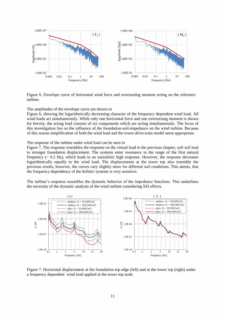
Figure 6. Envelope curve of horizontal wind force and overturning moment acting on the reference
turbine.
The amplitudes of the envelope curve are shown in
Figure 6, showing the logarithmically decreasing character of the frequency dependent wind load. All
wind loads act simultaneously. While only one horizontal force and one overturning moment is shown
for brevity, the acting load consists of six components which are acting simultaneously. The focus of
this investigation lies on the influence of the foundation-soil-impedance on the wind turbine. Because
of this reason simplification of both the wind load and the tower-drive-train model seem appropriate.
The response of the turbine under wind load can be seen in
Figure 7. The response resembles the response on the virtual load in the previous chapter, soft soil lead
to stronger foundation displacement. The systems enter resonance in the range of the first natural
frequency (~ 0.2 Hz), which leads to an unrealistic high response. However, the response decreases
logarithmically equally to the wind load. The displacements at the tower top also resemble the
previous results, however, the curves vary slightly more for different soil conditions. This attests, that
the frequency dependency of the holistic systems is very sensitive.
The turbine’s response resembles the dynamic behavior of the impedance functions. This underlines
the necessity of the dynamic analysis of the wind turbine considering SSI effects.
Figure 7. Horizontal displacement at the foundation top edge (left) and at the tower top (right) under
a frequency dependent wind load applied at the tower top node.
1.00E-02
1.00E+01
1.00E+04
1.00E+07
0.001 0.01 0.1 1 10 100
Am
pli
tud
e [N
]
Frequency [Hz]
( Fx )
1.00E-01
1.00E+02
1.00E+05
1.00E+08
0.001 0.01 0.1 1 10 100
Am
pli
tud
e [N
m]
Frequency [Hz]
( Mx )
1.0E-10
1.0E-07
1.0E-04
1.0E-01
0.1 1 2 5 10 15 20
ux [
m]
Frequency [Hz]
( a )
shallow: G = 50 [MN/m²]
shallow: G = 300 [MN/m²]
piles: G = 50 [MN/m²]
piles: G = 300 [MN/m²]
1.0E-10
1.0E-07
1.0E-04
1.0E-01
1.0E+02
0.1 1 2 5 10 15 20
ux [
m]
Frequency [Hz]
( b )
shallow: G = 50 [MN/m²]
shallow: G = 300 [MN/m²]
piles: G = 50 [MN/m²]
piles: G = 300 [MN/m²]

12
4. CONCLUSIONS
The presented impedance function of shallow or pile foundations of wind turbines on compliant soil
are dependent on the soil stiffness and the frequency. Strong SSI effects can be observed, especially
for the more complex models, for example a multi pile foundation resting in a multi layered soil,
which can be clearly seen in the frequency dependent display of the impedance functions. These
impedance functions are coupled to the FE model of a wind turbine tower. The holistic system
behavior resembles the influence of the SSI effects seen in the impedance functions. The application
of wind load in the frequency domain shows the importance of focusing the investigations on the low
frequency domain. There the wind load is highest and the natural frequencies of the holistic model are
in a range of 0.2 depending on the stiffness of the soil.
While this investigation focuses on the SSI aspects, further work should focus on holistic analysis
considering detailed tower and drive train modelling to simulate the overall turbine behavior.
5. ACKNOWLEDGMENTS
This research was financially supported by the German Federal Ministry for the Environment, Nature Conservation, Building and Nuclear Safety.
6. REFERENCES
Andersen, Assessment of lumped-parameter models for rigid footings, Computers & Structures, 88(23), pp.
1333-1347, 2010.
Bazeos, Hatzigeorgiou, Hondros, Karamaneas, Karabalis und Beskos, Static, Seismic and stability analyses of a
prototype wind turbine steel tower, Engineering Structures, 24(8), pp. 1015-1025, 2002.
Forchap, Wellenzahlanalyse zur Ermittlung des Baugrundaufbaus bei der Untersuchung von
Fundamentschwingungen und Bodenerschütterungen, Institut für Konstruktiven Ingenieurbau Ruhr-Universität
Bochum, Bochum, 1997.
Garcia, Reduction of seismically induced structural vibrations considering soil-structure interaction, Bochum,
2002.
Gazetas, Analysis of machine foundation vibrations: state of the art, Soil Dynamics and Earthquake Engineering,
1983, Vol.2, No.1, 1983.
Harte, Basu, Nielsen, Dynamic analysis of wind turbines including soil-structure-interaction, Engineering
Structures, 45, pp. 509-518, 2012.
Kausel, An Explicit Solution for the Green Functions for Dynamic Loads in Layered Media, Massachusetts
Institute of Technology, Cambridge, 1981.
Kausel, Early history of soil-structure interaction, Soil Dynamics and Earthquake Engineering, pp. 822-832,
September 2010.
Kaynia, Dynamic Stiffness and seismic response of pile groups, Cambridge, 1982.
Luco, Soil-structure interaction effects on the seismic response of tall chimneys, Soil Dynamics and Earthquake
Engineering, Vol. 5, No 3, pp. 170-177, 1986.
Lysmer, Vertical Motion of Rigid Footings, US Army Engineer Waterways Experiment Station, Corps of
Engineers, Vicksburg, 1965.
Medina, Padrón, Aznaréz, Santana, Maeso, Kinematic interaction factors of deep foundations with inclined piles,
Earthquake Engineering and Structural Dynamics Vol. 43, pp. 2035-2050, 2014.
Savidis, Hirschauer, Bode, Schepers, 3D-simulation of dynamic interaction between track and layered
subground, System Dynamics and Long-term Behaviour of Railway Vehicles, Track and Subgrade 6, pp. 431-
450, 2002.

13
Studer, Laue, Koller, Bodendynamik - Grundlagen, Kennziffern, Probleme und Lösungsansätze, Springer,
Zürich, 2007.
Taddei, Butenweg und Klinkel, Parametric Investigation of the Soil-Structure Interaction Effects on the Dynamic
Behavior of a Wind Turbine Considering a Layered Soil, Hoboken: Wiley-Blackwell, 2014.
Werkmeister, Jacobs, Shkara, Michel, Fontecha (2017). Soil-Structure Drive Train Interaction of wind turbine,
World Wind Energy Conference 2017, 12 June 2017, Malmö, Sweden.
Zania, Natural vibration frequency and damping of slender structures founded on monopiles, Soil Dynamics and
Earthquake Engineering 59, pp. 8-20, 2014.
Zhao, Maisser, Seismic response analysis of wind turbine towers including soil structure interaction, Journal of
Multi-Body Dynamics, 220, pp. 53-61,2006.