freestanding direct vent fireplaces models: rfsdv22, · 10001028 3 rfsdv22/32/42 freestanding...
TRANSCRIPT

INSTALLER: DO NOT DISCARD THIS MANUAL - LEAVE FOR HOMEOWNER
FreestandingDirect Vent FireplacesModels: RFSDV22,RFSDV32, RFSDV42
Homeowner’s Installation andOperating Manual
CERTIFIED
DESIGN
CERTIFIED
10001028 7/04 Rev. 2
INSTALLER/ CONSUMERSAFETY INFORMATION
PLEASE READ THIS MANUALBEFORE INSTALLING ANDUSING APPLIANCE
WARNING!IF THE INFORMATION INTHIS MANUAL IS NOTFOLLOWED EXACTLY, A FIREOR EXPLOSION MAY RESULTCAUSING PROPERTYDAMAGE, PERSONAL INJURY
OR LOSS OF LIFE.
FOR YOUR SAFETYInstallation and service mustbe performed by a qualifiedinstaller, service agency or thegas supplier.
WHAT TO DO IF YOU SMELLGAS:
• Do not try to light anyappliance.
• Do not touch any electricswitch; do not use any phonein your building.
• Immediately call your gassupplier from your neighbor'sphone. Follow the gassuppliers instructions.
• If you cannot reach your gassupplier call the firedepartment.
DO NOT STOREOR USE GASOLINE OROTHER FLAMMABLE VAPORSAND LIQUIDS IN THE VICINITYOF THIS OR ANY OTHERAPPLIANCE.
410 Admiral Blvd. • Mississauga, Ontario, Canada L5T 2N6 • 905-670-7777www.majesticproducts.com • www.vermontcastings.com
CFM Specialty Home Products

2 10001028
RFSDV22/32/42 Freestanding Direct Vent Fireplace
Table of ContentsPLEASE READ THE INSTALLATION & OPERATING INSTRUCTIONS BEFORE USING APPLIANCE.
Thank you and congratulations on your purchase of a CFM Specialty Home Products fireplaceIMPORTANT: Read all instructions and warnings carefully before starting installation. Failure to follow these instruc-
tions may result in a possible fire hazard and will void the warranty.
Installation InstructionsImportant Curing/Burn Information .....................................................................................3Locating the Fireplace ........................................................................................................3Fireplace Dimensions .........................................................................................................4Clearance to Combustibles ................................................................................................5Gas Specifications .............................................................................................................5Gas Inlet & Manifold Pressures ..........................................................................................5High Elevations ..................................................................................................................5Preparation .........................................................................................................................5Gas Line Installation ...........................................................................................................5Installation of Remote Switch for RN/RP gas valve ...........................................................6
General Venting InformationGeneral Venting Information - Termination Location .........................................................7Termination Clearances .....................................................................................................8General Information on Assembling Vent Pipes ................................................................8Twist Lock Pipes ................................................................................................................8How to use the Vent Graph ................................................................................................9Vertical Sidewall Applications ............................................................................................9Vertical Sidewall Installation .............................................................................................11Below Grade Installations (Snorkel) .................................................................................12Vertical Through-the-Roof Applications & Installation ......................................................13Twist Lock Venting Components ......................................................................................15
Operating InstructionsGlass Information .............................................................................................................16Louvre Removal ...............................................................................................................16Trim Removal ...................................................................................................................16Glass Removal .................................................................................................................16Glass Cleaning .................................................................................................................17Installation of Logs & Burner Lava Rock Material ............................................................17Ceramic Refractory ..........................................................................................................18Flame Adjustment ............................................................................................................18Temperature Adjustment ..................................................................................................18Flame Characteristics ......................................................................................................19Lighting Instructions .........................................................................................................20Troubleshooting ...............................................................................................................21
Maintenance ............................................................................................................................24Replacement ............................................................................................................................25Accessories ............................................................................................................................28Mobile Home Instructions ...........................................................................................................29Warranty ............................................................................................................................30

310001028
RFSDV22/32/42 Freestanding Direct Vent Fireplace
IMPORTANT:PLEASE REVIEW THE FOLLOWING CAREFULLYRemove any plastic from trim parts before turningthe fireplace ON.It is normal for fireplaces fabricated of steel to giveoff some expansion and/or contraction noises duringthe start up or cool down cycle. Similar noises arefound with your furnace heat exchanger or carengine. It is not unusual for your gas fireplace togive off some odor the first time it is burned. This isdue to the curing of the paint and any undetected oilfrom the manufacturing process.Please ensure that your room is well ventilated -
open all windows.It is recommended that you burn your fireplace for aleast six (6) hours the first time you use it. If optionalfan kit has been installed, place fan in the "OFF"position during this time.
Installation and Operating InstructionsThis gas fireplace should be installed by a qualified installer inaccordance with local building codes and with current CSA-B149.1 Installation codes for Gas Burning Fireplaces andEquipment and CAN/CSA Z 240.4 Canada.FOR U.S.A Installations follow local codes and/or the currentNational Fuel Gas Code. ANSI Z223.1/NFPA 54.FOR SAFE INSTALLATION AND OPERATION PLEASE NOTETHE FOLLOWING:1 . This fireplace gives off high temperatures and should be
located out of high traffic areas and away from furnitureand draperies.
2. Children and adults should be alerted to the hazards of thehigh surface temperatures of this fireplace and should stayaway to avoid burns or ignition of clothing.
3. Children should be carefully supervised when they are inthe same room as your fireplace.
4. Under no circumstances should this fireplace bemodified.Parts removed for servicing should be replacedprior to operating the fireplace again.
5. Installation and any repairs to this fireplace should becarried out by a qualified service person. A professionalservice person should be contacted to inspect this fireplaceannually.Make it a practice to have all of your gas fire-places checked annually. More frequent cleaning may berequired due to excess lint and dust from carpeting,bedding material, etc.
6. Control compartments, burners and air passages in thisfireplace should be kept clean and free of dust and lint.Make sure that the gas valve and pilot light are turned offbefore you attempt to clean this fireplace.
7, The venting system(chimney) of this fireplace should bechecked at least once a year and if needed your ventingsystem should be cleaned.
8. Keep the area around your fireplace clear of combustiblematerials, gasoline and other flammable vapour andliquids. This fireplace should not be used as a drying rackfor clothing,nor should Christmas stockings or decorationsbe hung in the area of it.
9. Under no circumstances should any solid fuels(wood,coal,paper or cardboard etc.)be used in this fire-place.
10.The flow of combustion and ventilation air must not beobstructed in any way.
11.When the fireplace is installed directly on carpeting, vinyltile or any combustible material other than wood, thefireplace must be installed on a metal or wood panelextending the full width and depth of the fireplace.
12.This fireplace requires adequate ventilation andcombustion air to operate properly.
13.This fireplace must not be connected to a chimney flueserving a separate solid fuel burning fireplace.
Proposition 65 Warning: Fuels used in gas,woodburning or oil fired appliances, and the productsof combustion of such fuels, contain chemicals knownto the State of California to cause cancer, birth defectsand other reproductive harm.California Health & Safety Code Sec. 25249.6
A) *Flat on wall corner B) *Room dividerC) Island D) Cross cornerE) Flat on wall
* A & B must maintain a 12" (305mm) clearance between the wall andside glass of fireplace.
There is a minimum vertical rise required for the ventingwhich varies depending on the application. The maximumhorizontal run also has restrictions. Become familiar withthe venting instructions starting on page 7, before startingthe installation.
Locating the Fireplace
12 in. (305mm)
A
12 in. (305mm)
B
C
D
E
Fig. 1 Locating gas fireplace.

4 10001028
RFSDV22/32/42 Freestanding Direct Vent Fireplace
A
B
C D E
F
G
H
J
I
K
A
C
B
D E
F
K
G
H
I
J
A
B
C
N
K
D M
J
I
H
L
RFSDV22
RFSDV32
RFSDV42
Fireplace Dimensions
Ref. RFSDV22 RFSDV32 RFSDV42A 26" (660mm) 25" (635mm) 28¹⁄₄" (717mm)B 26" (660mm) 24¹⁄₈" (613mm) 28¹⁄₄" (717mm)C 15¹⁄₄" (387mm) 16" (406mm) 17⁷⁄₈" (454mm)D 19¹⁄₄" (488mm) 20" (508mm) 22³⁄₄" (578mm)E 18⁵⁄₈" (473mm) 19" (483mm) -- --F 21" (533mm) 21" (533mm) -- --G 31¹⁄₂" (800mm) 31³⁄₄" (806mm) -- --H 17³⁄₄" (451mm) 17³⁄₄" (451mm) 22³⁄₄" (578mm)I 29⁵⁄₈" (752mm) 29⁵⁄₈" (752mm) 33⁵⁄₈" (854mm)J 9⁵⁄₈" (244mm) 9" (229mm) 10⁵⁄₈" (270mm)K 6¹⁄₂" (165mm) 6¹⁄₂" (165mm) 7" (178mm)L -- -- -- -- 36³⁄₈" (924mm)M -- -- -- -- 14³⁄₁₆" (360mm)N -- -- -- -- 17³⁄₈" (441mm)
Fig. 2 Fireplace specifications.

510001028
RFSDV22/32/42 Freestanding Direct Vent Fireplace
Adequate clearances as listed below must bemaintained for servicing and proper operation:
Back ............................................................... 0" (0mm)Side .......................................................... 12" (305mm)Floor ............................................................... 0" (0mm)Top ........................................................... 36" (914mm)Corner .................................... 0" to Back Edges (0mm)Vent Pipe...................................................... 1" (25mm)
Clearance to Combustibles
Gas SpecificationsMax. Min.Input Input
Model Fuel Gas Control B.T.U.H B.T.U.H.
RFSDV22RN Natural Gas Millivolt Hi/Lo 30,000 21,000
RFSDV22RP Propane Gas Millivolt Hi/Lo 30,000 22,500
RFSDV22TN Natural Gas Thermostatic 30,000 21,000
RFSDV22TP Propane Gas Thermostatic 30,000 22,500
RFSDV32RN Natural Gas Millivolt Hi/Lo 30,000 21,000
RFSDV32RP Propane Gas Millivolt Hi/Lo 30,000 22,500
RFSDV32TN Natural Gas Thermostatic 30,000 21,000
RFSDV32TP Propane Gas Thermostatic 30,000 22,500
RFSDV32RMH Nat/Prop Millivolt Hi/Lo 30,000 N/A
RFSDV42RN Natural Gas Millivolt Hi/Lo 40,000 28,000
RFSDV42RP Propane Gas Millivolt Hi/Lo 37,000 27,750
RFSDV42TN Natural Gas Thermostatic 40,000 28,000
RFSDV42TP Propane Gas Thermostatic 37,000 27,750
This appliance may be installed in an aftermarketpermanently located, manufactured (mobile) home,where not prohibited by local codes.
This appliance is only for use with the type of gasindicated on the rating plate. This appliance is notconvertible for use with other gases, unless acertified kit is available and used.
Natural LP (Propane)
Inlet Minimum 4.5" w.c. 11.0" w.c.Inlet Maximum 14.0" w.c. 14.0" w.c.Manifold Pressure 3.5" w.c. 10.0" w.c.
Gas Inlet and Manifold Pressures
ANSI.Z21.88a-1998 / CSA 2.33a - M98Vented Gas Fireplace Heaters
RFSDV22 / RFSDV32 / RFSDV42Certified To
Preparation
The use of wall paper adjacent to thisfireplace is not recommended, as thehigh temperatures given off by thisfireplace may adversely effect the bindersin the adhesive used to apply the wallpa-per.
Before beginning, remove the glass door from thefireplace. Also check to make sure there is no hiddendamage to the fireplace. Take a minute and plan outthe gas, vent and electrical supply. See Glass RemovalSection.
Gas Line Installation
When purging gas line, the front glassmust be removed.
The gas pipeline can be brought in through the rear ofthe fireplace as well as the bottom. Knockouts areprovided on the bottom behind the valve to allow forthe gas pipe installation and testing of any gas connec-tion. It is most convenient to bring the gas line infrom the rear right side of the valve, as this allowsfan installation or removal without disconnectingthe gas line.
The gas line connection can be made with properlytinned 3/8" copper tubing, 3/8" rigid pipe or anapproved flex connector. Since somemunicipalities have some additional local codes, itis always best to consult your local authority andthe CSA- B149.1 installation code.
For U.S. Installations consult the current NationalFuel Gas Code, ANSI Z223.1.
Always check for gas leaks with a mildsoap and water solution. Do not use anopen flame for leak testing.
The gas control is equipped with a captured screw typepressure test point, therefore it is not necessary toprovide a 1/8" test point up stream of the control.
High Elevations
Input ratings are shown in BTU per hour andare certified without deration for elevations upto 4,500 ft. (1,370 m) above sea level. Forelevations above 4,500 ft. (1,370 m) in USA,installations must be in accordance with thecurrent ANSI Z223.1 and/ or local codes havingjurisdiction.
In Canada, please consult provincial and/ orlocal authorities having jurisdiction forinstallations at elevations above 4,500 ft.(1,370 m).
6 10001028
RFSDV22/32/42 Freestanding Direct Vent Fireplace
Do not use this fireplace if any part ofthis fireplace has been under water.Immediately call a qualified servicetechnician to inspect the heater and toreplace any part control which has beenunder water.
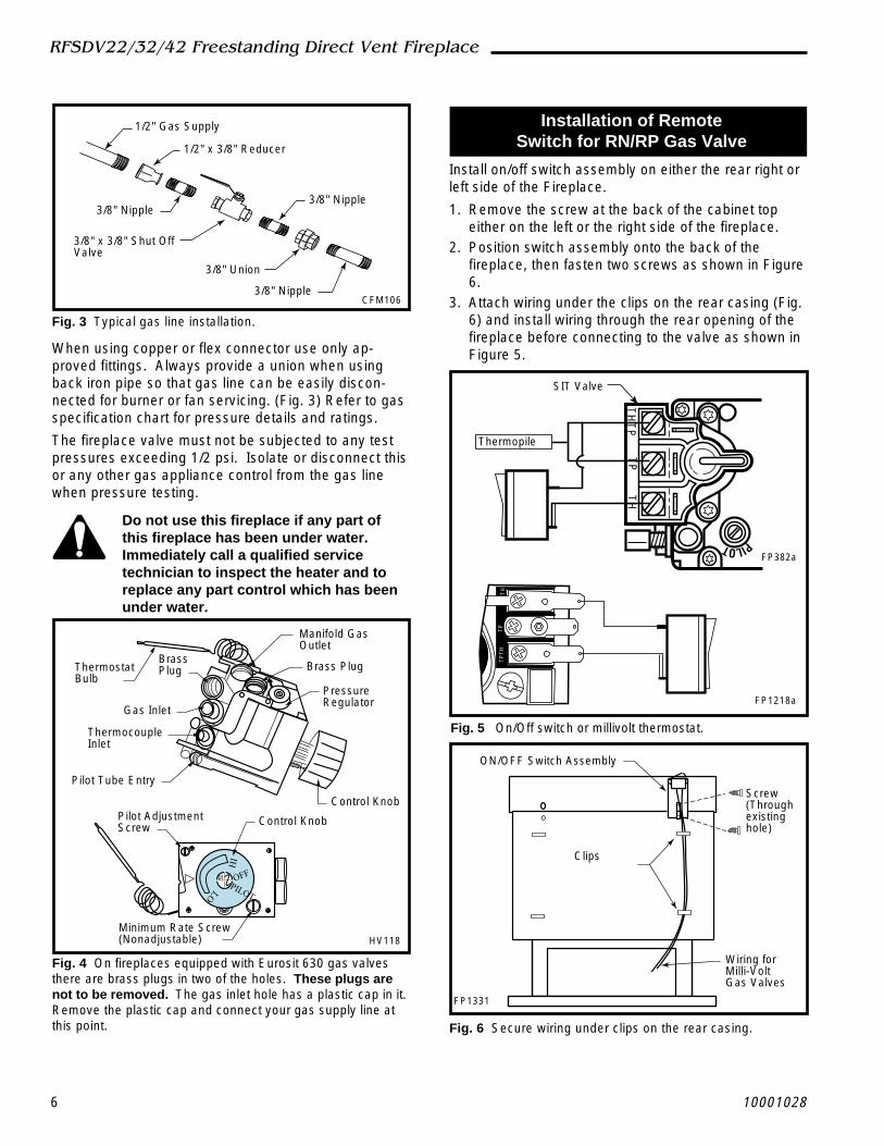
Installation of RemoteSwitch for RN/RP Gas Valve
Install on/off switch assembly on either the rear right orleft side of the Fireplace.
1. Remove the screw at the back of the cabinet topeither on the left or the right side of the fireplace.
2. Position switch assembly onto the back of thefireplace, then fasten two screws as shown in Figure6.
3. Attach wiring under the clips on the rear casing (Fig.6) and install wiring through the rear opening of thefireplace before connecting to the valve as shown inFigure 5.
1/2" Gas Supply
1/2" x 3/8" Reducer
3/8" Nipple
3/8" x 3/8" Shut OffValve
3/8" Nipple
3/8" Union
3/8" NippleCFM106
Fig. 3 Typical gas line installation.
When using copper or flex connector use only ap-proved fittings. Always provide a union when usingback iron pipe so that gas line can be easily discon-nected for burner or fan servicing. (Fig. 3) Refer to gasspecification chart for pressure details and ratings.
The fireplace valve must not be subjected to any testpressures exceeding 1/2 psi. Isolate or disconnect thisor any other gas appliance control from the gas linewhen pressure testing.
it
HI
LO
OFF
PILOT
Manifold GasOutlet
Brass Plug
PressureRegulator
ThermostatBulb
BrassPlug
Gas Inlet
ThermocoupleInlet
Pilot Tube Entry
Control KnobPilot AdjustmentScrew Control Knob
Minimum Rate Screw(Nonadjustable) HV118
Fig. 4 On fireplaces equipped with Eurosit 630 gas valvesthere are brass plugs in two of the holes. These plugs arenot to be removed. The gas inlet hole has a plastic cap in it.Remove the plastic cap and connect your gas supply line atthis point.
PILOT
TH
TP
TP
TH
SIT Valve
Thermopile
FP382a
Fig. 5 On/Off switch or millivolt thermostat.
TP
TH
TH
TP
FP1218a
ON/OFF Switch Assembly
Screw(Throughexistinghole)
Clips
Wiring forMilli-VoltGas Valves
FP1331
Fig. 6 Secure wiring under clips on the rear casing.

710001028
RFSDV22/32/42 Freestanding Direct Vent Fireplace
V
V
V
V
V
V
V
X
X
X
D
E
B
B B
C
BM
B
A
JK
F
L
VENT TERMINATION AIR SUPPLY INLET AREA WHERE TERMINAL IS NOT PERMITTED
H
I
FixedClosedFixed
Closed
OperableOperable Fixed
Closed
VB
INSIDECORNER DETAIL
V
A
G
V
NN
V
V
G
G
A
CFM145a
General Venting Information - Termination Location
A = Clearance above grade, veranda, porch, 12” (30cm) 12” (30cm)deck, or balcony
B = Clearance to window or door that may be 6” (15cm) for appliances 6” (15cm) for appliancesopened < 10,000Btuh (3kW), 12” (30cm) < 10,000 Btuh (3kW), 9”
for appliances > 10,000 Btuh (3kW) and (23cm) for appliances > 10,000< 100,000 Btuh (30kW), 36” (91cm) Btuh (3kW) and < 50,000 Btuhfor appliances > 100,000 Btuh (30kW) (15kW), 12” (30cm) for
appliances > 50,000 Btuh (15kW)C = Clearance to permanently closed window 12” (305mm) recommended to 12” (305mm) recommended to
prevent window condensation prevent window condensationD = Vertical clearance to ventilated soffit located
above the terminal within a horizontal 18” (458mm) 18” (458mm)distance of 2 feet (610mm) from the centerline of the terminal
E = Clearance to unventilated soffit 12” (305mm) 12” (305mm)F = Clearance to outside corner see next page see next pageG = Clearance to inside corner (see next page) see next page see next pageH = Clearance to each inside of center line 3’ (914mm) within a height of 15’ (4.6m) 3’ (914mm) within a height of 15’
extended above meter/regulator assembly above the meter/regulator assembly (4.6m) above the meter/regulatorassy
I = Clearance to service regulator vent outlet 3’ (914mm) 3’ (914mm)J = Clearance to nonmechanical air supply inlet 6” (15cm) for appliances < 10,000 6” (15cm) for appliances
to building or the combustion air inlet to any Btuh (3kW), 12” (30cm) for < 10,000 Btuh (3kW), 9”other appliances appliances > 10,000 Btuh (3kW) and < (23cm) for appliances > 10,000
100,000 Btuh (30kW), 36” (91cm) Btuh (3kW) and < 50,000 Btuhfor appliances > 100,000 Btuh (30kW) (15kW), 12” (30cm) for
appliances > 50,000 Btuh (15kW)K = Clearance to a mechanical air supply inlet 6’ (1.83m) 3’ (91cm) above if within 10’
(3m) horizontallyL = Clearance above paved sidewalk or paved 7’ (2.13m)† 7’ (2.13m)†
driveway located on public propertyM = Clearance under veranda, porch, deck or 12” (30cm)‡ 12” (30cm)‡
balconyN = Clearance above a roof shall extend a minimum of 24” (610mm) above the highest point when it passes through the roof
surface, and any other obstruction within a horizontal distance of 18” (450mm).1 In accordance with the current CSA-B149 Installation Codes2 In accordance with the current ANSI Z223.1/NFPA 54 National Fuel Gas Codes† A vent shall not terminate directly above a sidewalk or paved driveway which is located between two single family dwellings andserves both dwellings‡ only permitted if veranda, porch, deck or balcony is fully open on a minimum 2 sides beneath the floor:NOTE: 1. Local codes or regulations may require different clearances.
2. The special venting system used on Direct Vent Fireplaces are certified as part of the appliance, with clearances tested andapproved by the listing agency.
Canadian Installations1 US Installations2
8 10001028
RFSDV22/32/42 Freestanding Direct Vent Fireplace
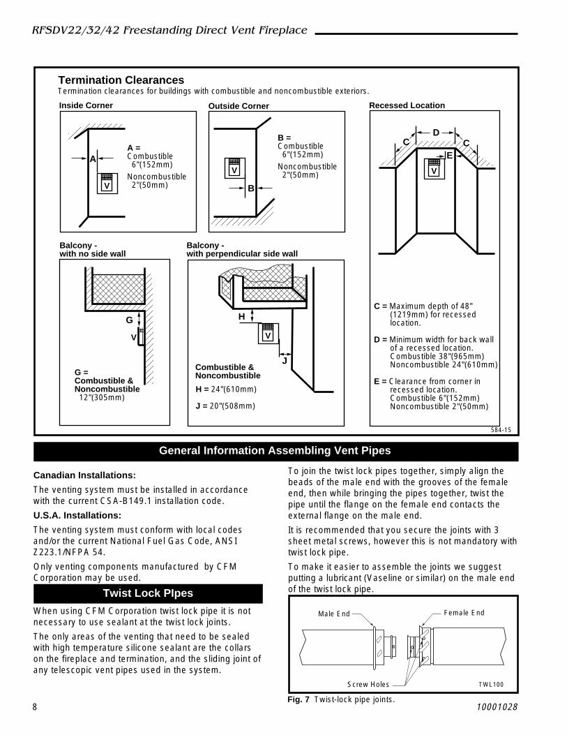
Outside CornerInside Corner
Termination ClearancesTermination clearances for buildings with combustible and noncombustible exteriors.
A =Combustible 6"(152mm)Noncombustible 2"(50mm)
B =Combustible 6"(152mm)Noncombustible 2"(50mm)
A
Balcony - with no side wall
G = Combustible &Noncombustible 12"(305mm)
G
Balcony - with perpendicular side wall
H = 24"(610mm)
J = 20"(508mm)
H
J
B
Recessed Location
C = Maximum depth of 48" (1219mm) for recessed location. D = Minimum width for back wall of a recessed location. Combustible 38"(965mm) Noncombustible 24"(610mm)
E = Clearance from corner in recessed location. Combustible 6"(152mm) Noncombustible 2"(50mm)
CD
CE
V
V
Combustible &Noncombustible
V V
V
584-15
General Information Assembling Vent Pipes
Canadian Installations:
The venting system must be installed in accordancewith the current CSA-B149.1 installation code.
U.S.A. Installations:
The venting system must conform with local codesand/or the current National Fuel Gas Code, ANSIZ223.1/NFPA 54.
Only venting components manufactured by CFMCorporation may be used.IST LOCK
Twist Lock PIpes
When using CFM Corporation twist lock pipe it is notnecessary to use sealant at the twist lock joints.
The only areas of the venting that need to be sealedwith high temperature silicone sealant are the collarson the fireplace and termination, and the sliding joint ofany telescopic vent pipes used in the system.
To join the twist lock pipes together, simply align thebeads of the male end with the grooves of the femaleend, then while bringing the pipes together, twist thepipe until the flange on the female end contacts theexternal flange on the male end.
It is recommended that you secure the joints with 3sheet metal screws, however this is not mandatory withtwist lock pipe.
To make it easier to assemble the joints we suggestputting a lubricant (Vaseline or similar) on the male endof the twist lock pipe.
Male End Female End
Screw Holes TWL100
Fig. 7 Twist-lock pipe joints.

910001028
RFSDV22/32/42 Freestanding Direct Vent Fireplace
How to Use the Vent Graph
1. Determine the height of the centre of the horizontalvent pipe exiting through the outer wall. Using thisdimension on the Sidewall Vent Graph (Fig. 8 or 9),locate the point it intersects with the slanted graphline.
2. From the point of this intersection, draw a verticalline to the bottom of the graph.
3. Select the indicated dimension, and position the fire-place in accordance with same.
EXAMPLE A:
If the vertical dimension from the floor of the fireplaceis 11' (335cm) the horizontal run to the face of theouter wall must not exceed 14' (427cm).
EXAMPLE B:
If the vertical dimension from the floor of the fireplaceis 7' (214cm), the horizontal run to the face of the outerwall must not exceed 8.5' (259cm).
For RFSDV22 & RFSDV32
3
4
5
6
7
8
9
10
11
12
13
14
15
16
17
18
19
20
21
22
23
24
25
26
27
28
29
30
3 4 5 6 7 8 9 10 11 12 13 14 15 16 17 18 19 20
eg: A
eg: B
Vertical D
imension from
the Floor of the F
ireplace to theC
enter of the Horizontal V
ent Pipe
Horizontal Dimension
Fig. 8 Sidewall venting graph for use with RFSDV22/32.
Vertical D
imension from
the Floor of the F
ireplaceto the C
enter of the Horizontal V
ent Pipe
Horizontal Dimension
3
4
5
6
7
8
9
10
11
12
13
14
15
16
17
18
19
20
21
22
23
24
25
26
27
28
29
30
3 4 5 6 7 8 9 10 11 12 13 14 15 16 17 18 19 20
eg: A
eg: C
RFSDV42ONLY
For RFSDV42
Fig. 9 Sidewall venting graph for use with RFSDV42 only.
EXAMPLE C: (only RFSDV42)If the vertical dimension from the floor of the fireplace is7' (214mm), the horizontal run to the face of the outerwall must not exceed 8' (244cm).Refer to Page 12 for venting requirements forsnorkels.
Vertical Sidewall Applications
Since it is very important that the venting systemmaintain its balance between the combustion airintake and the flue gas exhaust, certain limitationsas to vent configurations apply and must bestrictly adhered to.
The graph showing the relationship between verticaland horizontal side wall venting will help to determinethe various lengths allowable. (Fig. 8 or 9)
Minimum clearance between vent pipesand combustible materials is 1" (25mm)on top, bottom and sides unless other-wise noted.

10 10001028
RFSDV22/32/42 Freestanding Direct Vent Fireplace
• The maximum number of elbow degrees in a systemis 270°. (Fig. 13)
20'(610cm)
7.5'(229cm)
SupportStraps Every3' (914mm)
Firestop / Zero ClearanceSleeve
FP1334
Fig. 12 Support straps for horizontal runs.
SupportStrapsEvery 3'(914mm)
When vent termination exits through foundations lessthan 20" (508mm) below siding outcrop, the vent pipemust flush up with the siding. A 7DVSS must also beused.
It is always best to locate the fireplace in such a waythat minimizes the number of offsets and horizontalvent length.
The horizontal vent run refers to the total length of ventpipe from the flue collar of the fireplace to the face ofthe outer wall.
Horizontal plane means no vertical rise exists onthis portion of the vent assembly.
• The maximum number of 90° elbows per side wallinstallation is three (3).
• For RFSDV22 & RFSDV32 the maximumhorizontal run off a minimum 12" (305mm)vertical rise is 3' (914mm). (Fig. 10)
• For the RFSDV42 a minimum of 24" (610mm)vertical rise is required for a maximumhorizontal run of 3'(914mm). (Fig. 10)
• If a 90° elbow is used in the horizontal vent run(level height maintained) the maximum horizontalvent length is reduced by 36" (914mm). (Fig. 10)This does not apply if the 90° elbows are used toincrease or redirect a vertical rise. (Fig. 11)
Example: According to the chart the maximum hori-zontal vent length is 20' (6m) and if a 90° elbow isrequired in the horizontal vent it must be reduced to 17'(5.2m).
(Fig. 11 Dimension A plus B must not be greater than17' (5.2m))
• The maximum number of 45° elbows permitted perside wall installation is two (2). These elbows can beinstalled in either the vertical or horizontal run. (Fig.13)
• For each 45° elbow installed in the horizontalrun, the length of the horizontal run MUST bereduced by 18" (45cm). This does not apply if the45° elbows are installed on the vertical part ofthe vent system.
7.5 ft.2286 mm
A + B = 17 ft. (5.2 m) max.
FP1333
Fig. 11 Horizontal run reduction.
3 FT(92cm)
x
FP1332
Fig. 10 Maximum horizontal run with vertical rise.
RFSDV22/32X = 12" (305mm)RFSDV42X = 24" (610mm)
12
3
4
FP1335
Fig. 13 Maximum number of elbows.
Sample: 1 - 90°2 - 45°3 - 45°4 - 90°
Total 270°

1110001028
RFSDV22/32/42 Freestanding Direct Vent Fireplace
Vertical Sidewall Installation
Step 1Locate the vent opening on the wall. It may be neces-sary to first position the fireplace and measure toobtain hole location. Depending on whether the wall iscombustible or noncombustible, cut opening to correctsize. (Fig. 14) For combustible walls, first frame inopening.
Combustible Walls: Cut a 9³⁄₈" x 9³⁄₈" (240mm x240mm) hole through the exterior wall and frame asshown. (Fig. 14)
Noncombustible Walls: Hole opening must be 7¹⁄₂"(190mm) in diameter.
Step 3Place fireplace into position. (Fig. 16) Measure thevertical length (X) required form the base of the fluecollars to the center of the wall opening.
Vent Opening for Combustible Wall9³⁄₈"
(240mm)
9³⁄₈"(240mm)
Framing Detail
Fireplace Hearth
Vent Opening for Noncombustible Wall
7¹⁄₂'(190mm)
VO584-100
Fig. 14 Locate vent opening on wall.
Max. Length12" (294mm)
Adjustable ZeroClearance Sleeve
Adjustable Zero Clearance Sleeve
#8 Screws (2)
Firestop
ZCS101
#8 Screws (2)
#8 Screws(2)
Fig. 15 Adjustable zero clearance sleeve.
Step 2Measure wall thickness and cut zero clearance sleeveparts to proper length (MAXIMUM 12"). Assemblesleeve and attach to firestop with #8 sheet metalscrews (supplied). Install firestop assembly. (Fig. 15)
Zero clearance sleeve is only requiredfor combustible walls.
X
FP1336
Fig. 16 Vertical length requirement.
Step 4Apply a bead of silicone to the inner and outer fluecollars of the fireplace (Fig. 17) and using appropriatelength of pipe section(s), attach to fireplace with three(3) screws. Follow with the installation of the inner andouter elbow, again secure joints as described on Pages8 and 9.
Bead of Sealant
FP1337
Fig. 17 Apply a bead of silicone to the inner and outer fluecollars.
Step 5Measure the horizontal length requirement including a2" overlap, i.e. from the elbow to the outside wall faceplus 2" (or the distance required if installing a second90° elbow). (Fig. 18)

12 10001028
RFSDV22/32/42 Freestanding Direct Vent Fireplace
FP1340
Fig. 20 Attach vent termination.
Below Grade Installations
When it is not possible to meet the required ventterminal clearances of 12" (305mm) above grade levela starter vent kit is recommended. It allows installationdepth of down to 7" (178mm) below grade level. The 7"is measured from the center of the horizontal vent pipeas it penetrates through the wall.
If venting system is installed below ground,we recommend a window well with adequateand proper drainage.
Ensure sidewall venting clearances are observed.
If installing a snorkel a minimum 24" vertical rise isnecessary. The maximum horizontal run with the 24"vertical pipe is 36" (915mm). This measurement istaken from the collar of the fireplace to the face of theexterior wall. See vent graph for extended horizontalrun if the vertical exceeds 24".
1. Establish vent hole through the wall. (Fig.14)2. Remove soil to a depth of approximately 16" below
base of snorkel. Install drain pipe. Install windowwell (not supplied). Refill hole with 12" of coarsegravel leaving a clearance of approximately 4" belowsnorkel. (Fig. 21)
3. Install vent system.4. Ensure a watertight seal is made around the vent
pipe coming through the wall.5. Apply high temperature sealant caulking (supplied)
around the 4" and 7" snorkel collars.6. Slide into vent pipe and secure to the wall.7. Level the soil so as to maintain a 4" clearance below
snorkel. (Fig. 21)
Step 6
NOTE: If using the charcoal wall plate, Part #52202-CG, and collar, part #52203CG, put them in placebefore putting the pipe sections through the wall.
Use appropriate length of pipe sections - telescopic orfixed - and install. The sections which go through thewall are packaged with the starter kit, and can be cut tosuit if necessary. (Fig. 19)
Sealing vent pipe and firestop gaps withhigh temperature sealant will restrict coldair being drawn in around the fireplace.
X
FP1338
Fig. 18 Measure horizontal venting length plus 2".
FP1339
Fig. 19 Use appropriate length pipe sections.
Step 7Apply high temperature sealant to 4" and 7" collars orthe termination one inch away form crimped end.Guide the vent terminations 4" and 7" collars into theirrespective vent pipes. Secure the termination to thewall with screws provided and caulk around the wallplate to weatherproof.
Support horizontal pipes every 36"(914mm) with metal pipe straps.
Check fireplace to make sure it is lev-elled and properly positioned.

1310001028
RFSDV22/32/42 Freestanding Direct Vent Fireplace
Firestop
7" Pipe
24"(608mm)Minimum
Snorkel
4" Clearance
Window Well
Ground
Gravel
Drain
Foundation Wall
* A minimum of 24" (608mm)vertical pipe must be installedwhen using the snorkel kit.* The 22" vertical rise (center tocenter) of the snorkel may beincluded for calculation of max.horizontal run.FP1341
Fig. 21 Below grade installation.
Screws
Snorkel
Wall Screws
FoundationRecess
Watertight SealAround Pipe
Sheet MetalScrews
BG401
Fig. 22 Snorkel installation, recessed foundation.
Vertical Through-the-Roof Applications
This Gas Fireplace has been approved for,
• Vertical installations up to 40 feet (12m) in height.Up to a 10 ft. horizontal vent run can be installedwithin the vent system using a maximum of two 90o
elbows. (Fig. 23)• Up to two 45o elbows may be used within the hori-
zontal run. For each 45o elbow used on the horizon-tal level the maximum horizontal length must bereduced by 18".
Do Not Back Fill Around Snorkel. SoilShould Not Be Less Than 4" BelowSnorkel.
If the foundation is recessed, use recess brackets (notsupplied) for securing lower portion of the snorkel.Fasten brackets to wall first and then secure to snorkelwith self drilling #8 x 1/2 sheet metal screws. It will benecessary to extend the vent pipes out as far as theprotruding wall face. (Fig. 22)
Example: Maximum horizontal length0 - 45o elbows 10 ft. (3m)1 - 45o elbows 8.5 ft. (2.6m)2 - 45o elbows 7 ft. (2m)
Maximum10' (305cm)
Minimum 8'(2.4m)Maximum40' (12.2m)
FP1342
Support StrapsEvery 3' (914mm)
Fig. 23 Vertical through the roof requirements.
• A minimum of an 8 ft. vertical rise.• Two sets of 45 degree elbow offsets within these
vertical installations. From 0 to a maximum of 8 ft. ofvent pipe can be used between elbows. (Fig. 24)
• 7DVCS must be used to support offsets. (Fig. 25)This application will require that you first determinethe roof pitch and use the appropriate starter kit.(See Venting Components List)
• The minimum height of the vent above thehighest point of penetration through the roof is 2feet. (Fig. 26)
40' (12m)
Max. 8'(2.44m)
Max. 8'(2.44m)
45°
45°
FP1343
Fig. 24 Typical offset installation.

14 10001028
RFSDV22/32/42 Freestanding Direct Vent Fireplace
9. Install storm collar and seal around the pipe.10. Add additional vent lengths for proper height. (Fig.
26)11. Apply high temperature sealant to 4" and 7" collars
of vertical vent termination and install.If there is a room above ceiling level, firestop spacermust be installed on both the bottom and the top sideof the ceiling joists. If an attic is above ceiling level a7DVAIS (Attic Insulation Shield) must be installed. (Fig.27)The enlarged ends of the vent section always face down-ward. (Fig. 28)
Attic InsulationShield
Joist
CeilingInstallation
11"(279mm)
Firestop Spacer
Nails (4)
11"(279mm)
FP1029
Fig. 27 Place firestop spacer(s) and secure.
3 #5 Sheet MetalScrews per JointSealant
StormCollar
TWL101a
Fig. 28 Roof flashing.
3 #5 SheetMetalScrews perJoint
SealantStormCollar
Vertical Through-the-Roof Installation
1. Locate your fireplace.2. Plumb to centre of the (4") flue collar from ceiling
above and mark position.3. Cut opening equal to 9³⁄₈" x 9³⁄₈" (240mm x 240mm).4. Proceed to plumb for additional openings through
the roof. In all cases, the opening must provide aminimum of 1 inch clearance to the vent pipe, i.e.,the hole must be at least 9³⁄₈" x 9³⁄₈" (240mm x240mm).
5. Place fireplace into position.6. Place firestop(s) #7DVFS or Attic Insulation Shield
#7DVAIS into position and secure. (Fig. 27)7. Install roof support (Fig. 25) and roof flashing mak-
ing sure upper flange of flashing is below the shin-gles. (Fig. 27)
8. Install appropriate pipe sections until above theflashing. (Fig. 27)
Typical CeilingSupport Application
(7DVCS)Typical Roof SupportApplication
FP1184
Fig. 25 Venting supports.
2' Min.
StormCollar
Roof Flashing
Roof Support
CeilingJoists
Joists
Attic InsulationShield
AtticInsulation
40'(12.2mm)
FP1344
Fig. 26 Typical straight up installation.
1510001028
RFSDV22/32/42 Freestanding Direct Vent Fireplace
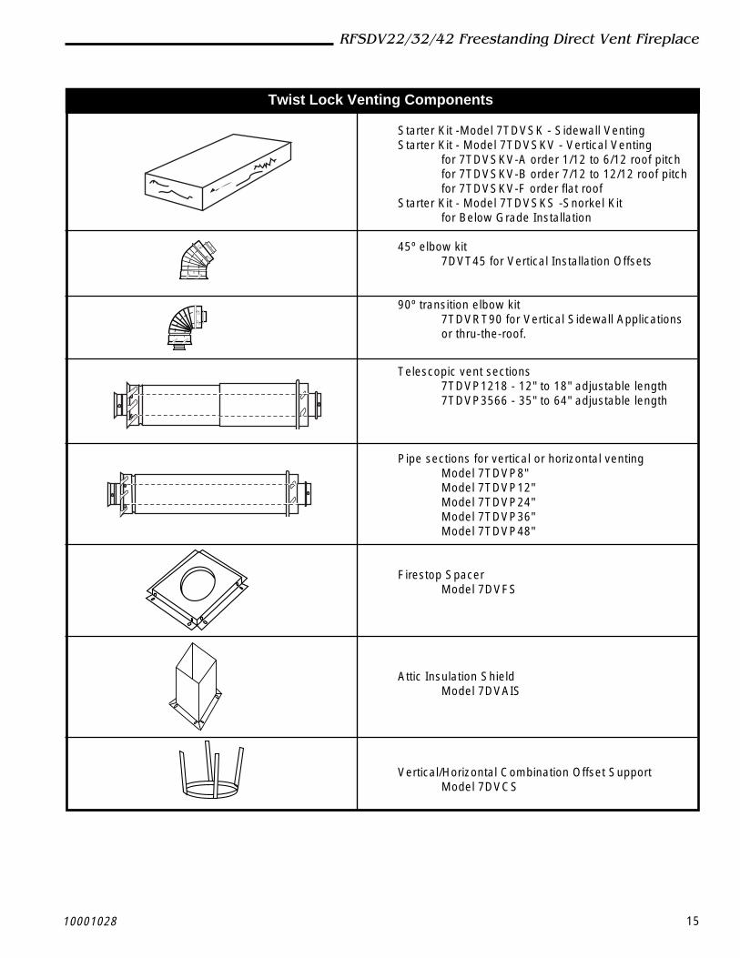
Twist Lock Venting Components
Starter Kit -Model 7TDVSK - Sidewall VentingStarter Kit - Model 7TDVSKV - Vertical Venting
for 7TDVSKV-A order 1/12 to 6/12 roof pitchfor 7TDVSKV-B order 7/12 to 12/12 roof pitchfor 7TDVSKV-F order flat roof
Starter Kit - Model 7TDVSKS -Snorkel Kitfor Below Grade Installation
45º elbow kit7DVT45 for Vertical Installation Offsets
90º transition elbow kit7TDVRT90 for Vertical Sidewall Applicationsor thru-the-roof.
Telescopic vent sections7TDVP1218 - 12" to 18" adjustable length7TDVP3566 - 35" to 64" adjustable length
Pipe sections for vertical or horizontal ventingModel 7TDVP8"Model 7TDVP12"Model 7TDVP24"Model 7TDVP36"Model 7TDVP48"
Firestop SpacerModel 7DVFS
Attic Insulation ShieldModel 7DVAIS
Vertical/Horizontal Combination Offset SupportModel 7DVCS

16 10001028
RFSDV22/32/42 Freestanding Direct Vent Fireplace
Operating InstructionsGlass Information
Only glass approved by CFM SpecialtyHome Products may be used for replace-ment.
• The use of substitute glass will void all productwarranties.
• Care must be taken to avoid breakage of the glass.• Under no circumstances should this fireplace be
operated without the front glass or with a brokenglass.
• Replacement of the glass (with gasket) as suppliedby the manufacturer should be done by a licencedqualified service person.
For the RFSDV42 both front bay windowglass and rear window glass need to beinstalled for proper performance. Underno circumstance should this fireplace beoperated without the rear window glassor with broken glass. Replacement of theglass (with gasket) as supplied by themanufacturer should be done by alicensed qualified person.
Louvre Removal
RFSDV22Remove the front louvre assembly by lifting up andoutward on the assembly.RFSDV32To remove louvres first remove the two (2) screws (Fig.29) fastening the louvre assembly to the fireplace. Liftthe louvre assembly straight out sliding the back guidesout of the fireplace body. (To reinstall, reverse).RFSDV42The top louvre is assembled with the bay WindowFrame and is not required to be removed.
Screws
FP1345Front View
Fig. 29 RFSDV32 louvre removal.
Trim Removal
RFSDV221. Remove frame window brass trim by lifting up and
out.2. Remove decorative cover, which was at the bottom
of the frame window trim by loosening two (2) nutson the underside of the cover.
RFSDV321. Remove the two (2) outer 3/8" nuts holding the
frame window brass trim in place. (Fig. 30)2. Remove the frame window brass trim by moving it
straight forward.RFSDV42Remove trim Bay Window, top and bottom, by pullingthem from the unit. They are held with magnets.
Glass Removal
RFSDV221. Remove frame window brass trim (See Trim
Removal section)2. Remove remaining bottom 3/8" nut at the bottom of
the frame window.3. Remove frame window by pulling it forward and up.RFSDV321 . Remove frame window brass trim (See Trim
Removal section)2. Remove remaining bottom 3/8" nut at the bottom of
the frame window.3. Remove 3/8" nut from each side of the frame
window. (Fig. 30)4. Remove frame window by pulling it forward and up.
Outer Nuts
SideNuts
Bottom Nut
GlassFrame
FP1347
Fig. 30 Glass removal.

1710001028
RFSDV22/32/42 Freestanding Direct Vent Fireplace
RFSDV421 . Remove both Bay Window brass trims (See Trim
Removal section).2. Open the two clamps (Fig. 31) underneath the Bay
Window that holds the Bay Window Frame andGlass Frame.
3. Lift and unhook the Bay Window assembly at thetop.
4. Lift and unhook the Glass Frame at the top.
WindowFrame
PullClamp Hook
PushClampHook
FP1346
Fig. 31 RFSDV42 glass removal.
Glass Cleaning
It will be necessary to clean the glass periodically.During start-up condensation, which is normal, formson the inside of the glass and causes lint, dust andother airborne particles cling to the glass surface. Alsoinitial paint curing may deposit a slight film on theglass. It is therefore recommended that the glass becleaned two or three times with a non-ammoniahousehold cleaner and warm water (we recommendgas fireplace glass cleaner). After that the glass shouldbe cleaned two or three times during each heatingseason depending on the circumstances present.
Clean glass after first two weeks ofoperation.Do not clean glass when hot.Do not use abrasive cleaners.Do not strike or slam the glass.
Installation of Logs &Burner Lava Rock Material
RFSDV22, RFSDV32 (Fig. 32)
1 . Remove front glass. (See "Glass Removal" section)2. Remove logs from packaging.3. Place rear log (KR4) on rear bracket (ensure log is
seated properly, leveled and centered to the unit), soit will not move from side to side and it is firmlypositioned on the bracket.
4. Slip front ember log (KR1) down in the front deflec-tor.
5. Place front left log (KR2) on top burner, left side.Use log's bottom holes to locate it into the leftbracket log locator studs.
6. Place front right log (KR3) on top of burner, rightside. Use log's bottom holes to locate it into the rightbracket log locator studs.
7. Place small lava rocks and ember material on top ofburner. (See Fig. 32 for proper location).
8. Place top left log (KR5) onto locator notches. En-sure log is secure.
9. Place top right log (KR6) onto locator notches.Ensure log is secure.
Top logs must be placed properly intonotches
KR2
KR5 KR6KR4
KR3
KR1
Burner Lava RockPlacementLG280
Fig. 32 RFSDV22/32 logs and burner lava rock placement.
RFSDV42 (Fig. 33)
1 . Remove bay window assembly and glass frame (see"Glass Frame Removal" section).
2. Remove logs from packaging.3. Place rear log (SR4) on rear bracket. Ensure log is
seated properly, leveled and centered to the unit, soit will not move from side to side and it is firmlypositioned onthe bracket.
4. Slip front emberlog (SR1) down in the front deflector.5. Place front left log (SR2) on top of burner, left side.
Use log's bottom holes to locate it into the leftbracket log locator studs.
6. Place front right log (SR3) on top of burner, rightside. Use log's bottom holes to locate it into the rightbracket log locator studs.
7. Place burner lava rock on top of burner. (Fig. 33)8. Place top right log (SR6) onto locator notches.
Ensure log is secure.9. Place top left log (SR5) onto locator notches. En-
sure log is secure.

18 10001028
RFSDV22/32/42 Freestanding Direct Vent Fireplace
SR2
SR5 SR6
SR4
SR3
SR1
Burner Lava RockPlacement LG281
Fig. 33 RFSDV42 log and burner lava rock placement.
Ceramic Refractory
RFSDV42 ONLY
1. Remove bay window assembly and glass frame (see"Glass frame Removal" section).
2. Remove logs from the unit.
Logs may be hot!
3. Remove refractory from packaging.Refractory are fragile and must be han-dled with care. Where at all possible, twohands should be used when handling.
4. Place center refractory piece at the very back of thefirebox.
5. Slide left or right side refractory along the side of thefirebox and on top of the bottom support channel. Besure to slide the panel back to hold the center piecein place and the leading edge faces forward.
6. Fasten top tab support against the refractory to holdit in place.
7. Repeat steps 5 and 6 for remaining side refactory.8. Insert refractory pieces into the Bay Window as
shown in Figure 35.
Leading Edge Leading Edge
Left SideCenter
Right SideFP1348
Fig. 34 Ceramic panels.
FP1349
Fig. 35 Bay window ceramic refractory.
Flame Adjustment (RN/RP Models)
For units equipped with Hi/Lo valves, flame adjustmentis accomplished by rotating the Hi/Lo adjustment knoblocated near the centre of the gas control. (Fig. 36 &37)
LO
HI
Turncounterclockwise
to decreaseflame height
Turn clockwiseto increase
flame height
Fig. 36 Flame adjustment knob for Honeywell valve.
LO
HITurn counterclockwise
to increaseflame height
Turn clockwiseto decreaseflame height
Fig. 37 Flame adjustment knob for SIT valve.
Temperature Adjustment (TN/TP Models)
The Hi/Lo reference on the control knob (Fig. 38) is toindicate a higher or lower temperature setting. Thissetting controls the heat by reducing then shutting offthe flame as the desired temperature is reached.Position the control knob where it effectively maintainsa comfortable room temperature.
Fig. 38 Temperature adjustment knob for TN/TP models.
1910001028
RFSDV22/32/42 Freestanding Direct Vent Fireplace
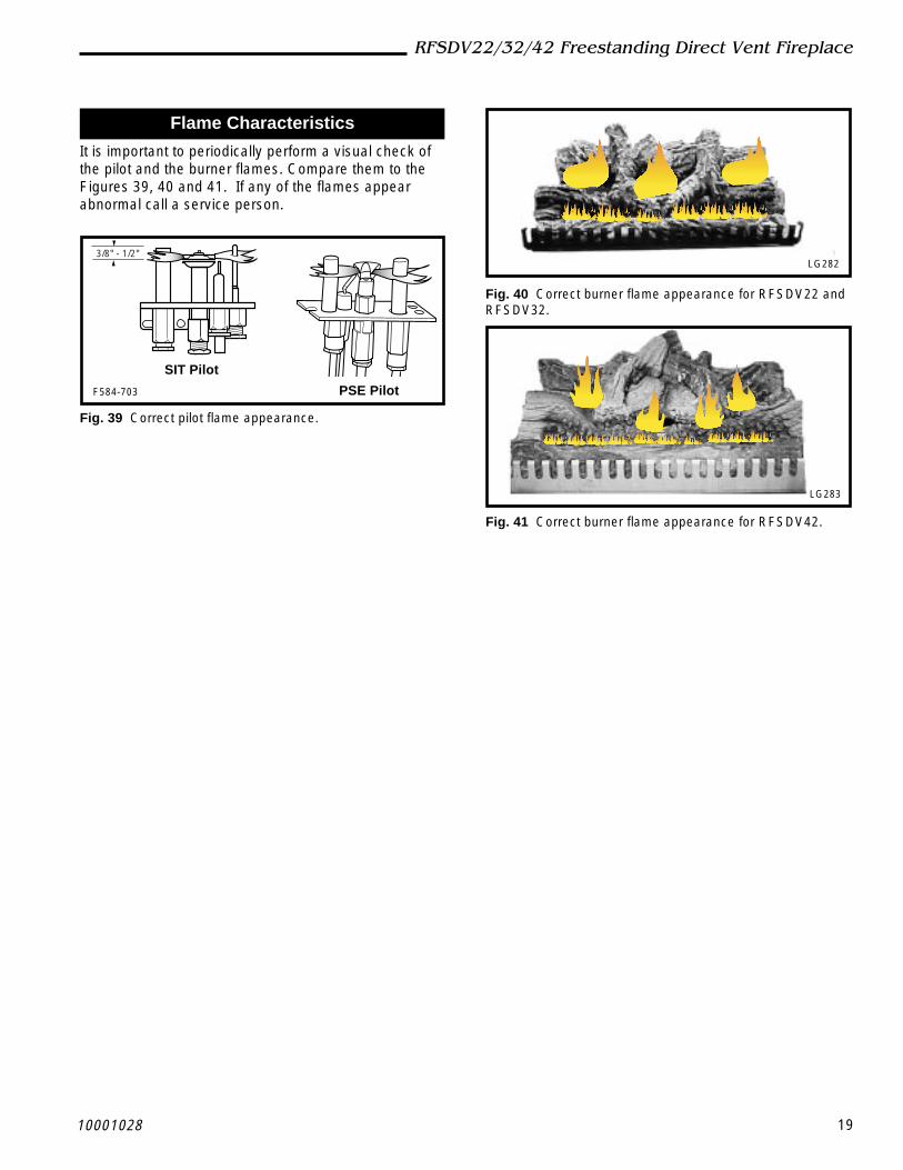
Flame Characteristics
It is important to periodically perform a visual check ofthe pilot and the burner flames. Compare them to theFigures 39, 40 and 41. If any of the flames appearabnormal call a service person.
3/8" - 1/2"
SIT Pilot
PSE PilotF584-703
Fig. 39 Correct pilot flame appearance.
LG282
Fig. 40 Correct burner flame appearance for RFSDV22 andRFSDV32.
LG283
Fig. 41 Correct burner flame appearance for RFSDV42.

20 10001028
RFSDV22/32/42 Freestanding Direct Vent Fireplace
3. Open control access panel.4. Push in gas control knob slightly and turn
clockwise to "OFF". Do not force.5. Close control access panel.
1. STOP! Read the safety information above.2. Turn off all electrical power to the fireplace.3. For MN/MP/TN/TP appliances ONLY, go on to
Step 4. For RN/RP appliances turn the On/Offswitch to “OFF” position or set thermostat tolowest level.
4. Open control access panel.5. Push in gas control knob slightly and turn
clockwise to "OFF".
10. Push the control knob all the way in and hold.Immediately light the pilot by repeatedly depress-ing the piezo spark ignitor until a flame appears.Continue to hold the control knob in for about one(1) minute after the pilot is lit. Release knob and itwill pop back up. Pilot should remain lit. If it goesout, repeat steps 5 through 8.
FOR YOUR SAFETY READ BEFORE LIGHTING
instructions.• If you cannot reach your gas supplier, call
the Fire DepartmentC. Use only your hand to push in or turn the gas
control knob. Never use tools. If the knob will notpush in or turn by hand, do not try to repair it, call aqualified service technician. Applying force or anyattempted repair may result in a fire or explosion.
D. Do not use this fireplace if any part has been underwater. Immediately call a qualified service techni-cian to inspect the heater and to replace any part ofthe control system and any gas control which hasbeen under water.
A. This heater has a pilot which must be lit manu-ally. When lighting the pilot follow these instruc-tions exactly.
B. BEFORE LIGHTING smell all around the heaterarea for gas. Be sure to smell next to the floorbecause some gas is heavier than air and willsettle on the floor.
WHAT TO DO IF YOU SMELL GAS• Do not try to light any fireplace• Do not touch any electric switch• Do not use any phone in your building• Immediately call your gas supplier from a
neighbor's phone. Follow the gas supplier's
To Turn Off Gas To Heater
Lighting And Operating Instructions
1. Turn the On/Off switch to "OFF" position or setthe thermostat to lowest setting.
2. Turn off all electric power to the fireplace ifservice is to be performed.
Lighting Instructions
6. Wait five (5) minutes to clear out any gas. Thensmell for gas, including near the floor. If yousmell gas, STOP! Follow "B" in the safetyinformation above. If you do not smell gas, goto the next step.
7. Remove glass door before lighting pilot. (SeeGlass Frame Removal section).
8. Visibly locate pilot by the main burner.9. Turn knob on gas control counterclockwise
to "PILOT".
• If knob does not pop up when released, stopand immediately call your service technician orgas supplier.• If after several tries, the pilot will not stay lit,turn the gas control knob to " " and call yourservice technician or gas supplier.
11. Replace glass door.12. Turn gas control knob to “ON” position.13. For RN/RP appliances turn the On/Off switch to
“ON” position or set thermostat to desired setting.14. Turn on all electrical power to the fireplace.
WARNING:If you do not follow these instructions exactly, a fire or explosionmay result causing property damage, personal injury or loss of life.
Euro SIT SIT NOVA Honeywell
PILOT
ON
OFF
ON
PILOT
OF
F
OFF5 4 3
21
OFF
Pilo
t
3/8" - 1/2"

2110001028
RFSDV22/32/42 Freestanding Direct Vent Fireplace
SIT 630 Gas ValveNOTE: Before trouble shooting the gas control system, be sure external gas shut off is in the "On" position.
WARNING: Before doing any gas control service work, remove glass front.
Symptom Possible Causes Corrective Action
1. Spark ignitor will not light A. Defective or misaligned Using a match, light pilot. If pilot lights, turn offelectrode at pilot. pilot and push the red button again. If pilot will not
light - check gap at electrode and pilot-should be1/8" to have a strong spark.
B. Defective ignitor (Push Button) Push Piezo Ignitor Button. Check for spark atelectrode and pilot. If no spark to pilot, and electrode wire is properly connected, replace ignitor.
2. Pilot will not stay lit after A. Defective pilot generator Check pilot flame. Must impinge on thermocoucarefully following lighting thermocouple. ple. Clean and or adjust pilot for maximum flameinstructions. impingement on thermocouple.
B. Defective automatic valve Turn valve knob to "Pilot". Maintain flow to pilot;operator. millivolt meter should read greater than 10 mV.
If the reading is okay and the pilot does not stayon, replace the gas valve. Note: An interrupterblock (not supplied) must be used to conduct thistest.
3. Pilot burning, no gas to A. Sensing bulb not in proper Make sure sensing bulb is located in bracket onburner, Valve knob "ON". location. the lower right hand side of fireplace.
B. Temperature sensing bulb Carefully examine sensing bulb and capillery tubedamaged or tubing to bulb for damage. If tubing is kinked, replace gas valve.kinked
4. Frequent pilot outage A. Pilot flame may be too low Clean and/or adjust pilot flame for maximum flameproblem. or blowing (high) causing the impingement on thermocouple.
pilot safety to drop out.B. Possible blockage of the vent Check the vent terminal for blockage (recycling flue
terminal. gases).
Troubleshooting the Gas Control System

22 10001028
RFSDV22/32/42 Freestanding Direct Vent Fireplace
Troubleshooting the Gas Control SystemHoneywell Millivolt Valve
Gas Supply On Supply Line Hooked UpShutoff Valve Open
NO
NO
NO
NO
Lockout Has Engaged. Wait 60 Seconds And Try Again.For Spark At Electrode While Depressing Piezo 1/8" Gap To Pilot Hood Needed.All Wiring ConnectionsReplace Piezo Ignitor
For Air In The LinesThermopile Needs A Minimum 325mv. Adjust Pilot Flame Height.All Wiring Connections.Replace ThermopileThermocouple Needs A Minimum of 14mv.Defective Valve. Turn To Pilot, Meter Should Read Greater Than 100 Mv. If Not, Replace.
Pilot Lights With Piezo Ignitor
YES
YES
YES
YES
Pilot Stays Lit
Pilot Lights Main Burner
System OK.
STARTCHECK
Valve Is Turned OnOn/off Switch Is Not Turned On. Watch For Grounded Wires!Thermopile Needs A Minimum 325mv.Plugged Burner Orifice.

2310001028
RFSDV22/32/42 Freestanding Direct Vent Fireplace
WARNING: Before doing any gas control service work, remove glass front.
SYMPTOM POSSIBLE CAUSES CORRECTIVE ACTION
1.Spark ignitor will not light A. Defective or misaligned Using a match, light pilot. If pilot lights, turn offelectrode at pilot. pilot and push the red button again. If pilot will not
light - check gap at electrode and pilot-should be1/8" to have a strong spark.
B. Defective ignitor (Push Button) Push Piezo Ignitor Button. Check for spark atelectrode and pilot. If no spark to pilot, and electrode wire is properly connected, replace ignitor.
2.Pilot will not stay lit after A. Defective pilot generator Check pilot flame. Must impinge on thermocarefully following lighting (thermocouple), remote wall couple/thermopile. Note: this pilot burner asseminstructions. switch. bly utilizes both-a thermocouple and a thermopile.
The thermocouple operates the main valveoperation (On and Off). Clean and or adjust pilot formaximum flame impingement on thermopile andthermocouple.
B. Defective automatic valve Turn valve knob to “Pilot”. Maintain flow to pilot;milivolt meter should read greater than 10 mV. Ifthe reading is okay and the pilot does not stay on,replace the gas valve. Note: An interrupter block(not supplied) must be used to conduct this test.
3.Pilot burning, no gas to A. Wall switch or wires defective Check wall switch and wires for proper connecmain burner tions. Jumper wire accross terminals at wall
switch, if burner comes on, replace defective wallswitch. If okay, jumper wires across wall switchwires at valve, if burner comes on, wires are faultyor connections are bad.
B. Thermopile may not be 1. Be sure wire connections from thermopile atgenerating sufficient gas valve terminals are tight and thermopile ismillivoltage. fully inserted into pilot bracket.
2. One of the wall switch wires may be grounded.Remove wall switch wires from valve terminals ifpilot now stays lit, trace wall switch wiring forground. May be grounded to fireplace or gassupply.
3. Check thermopile with millivolt meter. Takereading at thermopile terminals of gas valve.Should read 250-300 millivolts (minimum 150)while holding valve knob depressed in pilotposition and wall switch “Off”. Replace faultythermopile if reading is below specified minimum.
C. Plugged burner orifice. Check burner orifices for debris and remove.
D. Defective automatic valve Turn valve knob to “On”, place wall switch to “On”operator. millivolt meter should read greater than 100 mV. If
the reading is okay and the burner does not comeon, replace the gas valve.
4.Frequent pilot outage A. Pilot flame may be too low Clean and/or adjust pilot flame for maximum flameproblem. or blowing (high) causing the impingement on thermopile and thermocouple.
pilot safety to drop out.
B. Possible blockage of the vent Check the vent terminal for blockage (recycling theterminal. flue gases)
Troubleshooting the Gas Control System
NOTE: Before trouble shooting the gas control system, be sure external gas shut off is in the “On” position.SIT NOVA 820 Millivolt Valve

24 10001028
RFSDV22/32/42 Freestanding Direct Vent Fireplace
MaintenanceBurner and Burner Compartment
It is important to keep the burner and the burnercompartment clean. At least once per year the logs andlava rock/ember material should be removed and theburner compartment vacuumed and wiped out. Removeand replace the logs as per the instructions in thismanual.
Always handle the logs with care as theyare fragile and may also be hot if thefireplace has been in use.
Fan AssemblyThe fan unit requires periodic cleaning. At least onceper month in the operating season, open the lowerlouvre panels and wipe or vacuum the area around thefan to remove any build up of dust or lint.
Cleaning the Standing Pilot
Control SystemThe burner and control system consists of:
• main burner • pilot burner• gas orifice • thermopile• combination millivolt gas valve
Most of these components may require only an occa-sional checkup and cleaning and some may requireadjustment. If repair is necessary, it should be per-formed by a qualified technician.
In order to properly clean the burner and pilot assembly,turn off the gas to the unit, remove the window framepanel and logs exposing the burner and pilot assembly.Clean all foreign materials from the top of the burner.Check to make sure that burner parts are clean.
Visually inspect pilot. Brush or blow away any dust orlint accumulation. If pilot orifice is plugged, disassemblymay be required to remove any foreign material fromthe orifice or tubing.
To obtain proper operation, it is imperative that the pilotand burner's flame characteristics are steady, not liftingor floating.
Typically, the top 1/8" of the thermopile should beengulfed in the pilot flame. (Page 19, Fig. 39)
Brass CleaningClean the brass trim with a soft clean cloth, slightlydampened with lemon oil and buff with a soft dry cloth.Do not use brass polish or household cleaners as theseproducts will damage the trim. Lemon oil can beobtained at supermarkets or hardware stores.

2510001028
RFSDV22/32/42 Freestanding Direct Vent Fireplace
10a/b
29
30
27
5/6a,b
28
21a,b
44
41
42
43
31
32
36 a/b 37
39
46
45
it
HI
LO
OFF
PILOT
25a,b
39
40
33
47
26
10
33
43
34
35
38
43
39
1b
1d
1e
1f
1a
1c
3a/b
4
23
22
43
41
42
2
19
7 a/b
18
13
11
12 1716
LOHI
PILO
TAD
J
PILOT
ON
OFF
24a,b
1517
13
8 a/b
20
9 a/b
1d
1f
1c
1a
1e
1b
1028
CFM Specialty Home Products reserves the right to make changes in design, materials, specifications, prices and discontinue colors and productsat any time, without notice.
RFSDV22/32/42 Series

26 10001028
RFSDV22/32/42 Freestanding Direct Vent Fireplace
RFSDV22/32/42 Series (continued)Ref.Description RFSDV22 RFSDV32 RFSDV42
1. Log Set Complete 10000160 10000160 100002051a. Log Ember Front KR1 KR1 SR11b. Log Front Left KR2 KR2 SR21c. Log Front Right KR3 KR3 SR31d. Log Rear KR4 KR4 SR41e. Log Top Left KR5 KR5 SR51f. Log Top Right KR6 KR5 SR62. Burner Lava Rock (Package) 57897 57897 57897
3a. Burner with Tiles Nat. 57903 57903 100008663b. Burner with Tiles Prop. 57904 57904 10000867
4. Ceramic Tile (Single) 57803 57803 578035a. Orifice Front Nat. See Rating Plate for Orifice Size5b. Orifice Front Prop. See Rating Plate for Orifice Size6a. Orifice Main Nat. See Rating Plate for Orifice Size6b. Orifice Main Prop. See Rating Plate for Orifice Size7a. Orifice Pilot SIT Nat. 54273 54273 542737b. Orifice Pilot SIT Prop. 54272 54272 542728a. Orifice Pilot PSE Nat. 10001822 10001822 100018228b. Orifice Pilot PSE Prop. 10001823 10001823 100018239a. Pilot Assembly SIT Nat. 10000674 10000674 100006749b. Pilot Assembly SIT Prop. 10000675 10000675 10000675
10a. Pilot Assembly PSE Nat. 10001741 10001741 1000174110b. Pilot Assembly PSE Prop. 10001742 10001742 1000174211. Pilot SIT 10001295 10001295 1000129512. Pilot w/ignitor and cable PSE 10001824 10001824 1000182413. Pilot Tubing w/fittings 53211 53211 5321114. Manifold Tubing w/fittings 57318 57318 5731815. Thermocouple SIT 53373 53373 5337316. Thermocouple PSE 10001825 10001825 1000182517. Thermopile 51827 51827 5182718. Electrode Ignitor w/cable SIT 10001297 10001297 1000129719. Ignitor Piezo SIT 52464 52464 5093220. Ignitor Piezo Honeywell 20000062 20000062 20000062
21a. Valve SIT 820 Nat. 52677 52677 5267721b. Valve SIT 820 Prop. 52678 52678 5267822. Extension Knob Hi/Lo SIT (RN/RP) 10000165 10000165 5516223 Extension Knob On/Off SIT (RN/RP) 10000166 10000166 55163
24a. Valve Honeywell Nat. 10001782 10001782 1000178224b. Valve Honeywell Prop. 10001759 10001759 1000175925a. Valve Eurosit 630 Nat. 53448 53448 5344825b. Valve Eurosit 630 Prop. 53446 53446 5344626. Fan with Bracket 54103 54103 5410327. Electrical Cord (6ft.) 51865 51865 5186528. Fan Temperature Sensor 51704 51704 5170429. Speed Control 51738 51738 5173830. Speed Control Knob 51882 51882 5188231. Glass with Gasket - Front 52035 52035 5758132. Glass with Gasket - Side – 52032 –33. Gasket Glass 57316 57316 5731734. Glass Bay Window - Front – – 5747735. Glass Bay Window - Sides – – 57478
36a. Frame Window - Left Side – 52145 –

2710001028
RFSDV22/32/42 Freestanding Direct Vent Fireplace
RFSDV22/32/42 Series (continued)Ref. Description RFSDV22 RFSDV32 RFSDV4236b. Frame Window - Right Side – 52860 –37. Frame Window - Front 57244 57244 5759038. Bay Window Assy. (w/glass) – – 5759339. Trim Frame Window (PB) 53477 52027 57583(1)
40. Trim Front Louvre (PB) 53455 – –41. Top Louvre 57262 52019 –42. Front Louvre Assembly 57259 57908 5759143. Access Door Assembly (with handle) 53990 52030 5759244. Latch 52057 52057 5205745. Remote Switch 53606 53606 5360646. Remote Wire Harness with Terminals 10002582 10002582 10002582047. Clamp Frame Window – – 5417448. Ceramic Refractory Lining Kit (Not Shown) – – 1000084649. Ceramic Refractory Bay (ONLY Bay Set) (Not Shown) – – 10000847

28 10001028
RFSDV22/32/42 Freestanding Direct Vent Fireplace
Remote Control
Only for units with RN/RP valve.
Model Function(s) ControlledMRC1 On/Off Button Remote ControlMRC2 Temperature Control RemoteMRC3 Temperature Control w/digital
display & 24 hour programmableclock
IMT Wall Mounted Thermostat
AccessoriesFan Kits
FK24
Standard on RFSDV42
It will be easier to install the fan beforeconnecting the gas line to the fireplace.
1. Open front access door panel by pulling forward onbrass lip.
2. Install the fan through the opening at the back of thepedestal, with the outlet pointed up and the fanmounting bracket facing the back of the fireplace.(Fig. 43) The fan mounts over two studs which holdthe fan just below the firebox floor. Hold the fan inplace with the two nuts provided.
3. Locate the fan speed control/junction box on screwstuds provided on base of the fireplace. Tighten withnuts.
4. Install thermal sensor element on screw studslocated to the right of the gas valve on the burnerbase.
5. Plug in grounded service cord to a convenient wallreceptacle.
This fan assembly comes completely wiredto eliminate the need for electricians. Thiselectrical device, when installed, must beelectrically connected and grounded inaccordance with local codes. In theabsence of local codes, with the currentCSA C22.1 CANADIAN ELECTRICALCODE.
For U.S.A. installation: Follow local codesand the NATIONAL ELECTRICAL CODEANSI/NFPA No.70-1984.
BlackWhiteGround
FanTemperatureSensor
SpeedControl
FP1025
Fig. 42 FK24 fan wiring.
Should this fan require servicing, thepower supply must be disconnected. Forrewiring of any replacement compo-nents. (Fig. 42)
Stud
ThermalSensorLocation
Fan isinstalledat theback ofthepedestal
Fan SpeedControl/Junction Box
Valve
Top ViewFP1350
Fig. 43 FK24 placement.

2910001028
RFSDV22/32/42 Freestanding Direct Vent Fireplace
This gas fireplace should be installed by a qualified installer inaccordance with local building codes and with current CSA-B149.1 Installation codes for Gas Burning Fireplaces andEquipment and CAN/CSA Z 240 .4 Canada.
A manufactured home (mobile home) OEM installation mustconform with the Manufactured Home Construction and SafetyStandard, Title 24 CFR, Part 3280, or when such a standard is notapplicable, the Standard for Manufactured Home installations,ANSIINCSBCS A225.1, or Standard for Gas EquippedRecreational Vehicles and Mobile Housing CSA Z240.4.
The appliance when installed, must be electrically grounded inaccordance with local codes or, in the absence of local codes,with the National Electrical Code, ANSIINFPA 70, or the CanadianElectrical Code, CSA C22.1.
For safe installation and operation please note thefollowing:
1 . This fireplace gives off high temperatures and should belocated out of high traffic areas and away from furnitureand draperies.
2. Children and adults should be alerted to the hazards of thehigh surface temperatures of this fireplace and should stayaway to avoid burns or ignition of clothing.
3. Children should be carefully supervised when they are inthe same room as your fireplace.
4. Under no circumstances should this fireplace be modified.Parts removed for servicing should be replaced prior tooperating this fireplace again.
5. Installation and any repairs to this fireplace should becarried out by a qualified service person. A professionalservice person should be contacted to inspect this fireplaceannually. Make it a practice to have all of your gasfireplaces checked annually. More frequent cleaning maybe required due to excess lint and dust from carpeting,bedding material, etc.
6. Control compartments, burners and air passages in thisfireplace should be kept clean and free of dust and lint.Make sure that the gas valve and pilot light are turned offbefore you attempt to clean this fireplace.
7, The venting system(chimney) of this fireplace should bechecked at least once a year and if needed your ventingsystem should be cleaned.
8. Keep the area around your fireplace clear of combustiblematerials, gasoline and other flammable vapour andliquids. This fireplace should not be used as a drying rackfor clothing, nor should Christmas stockings or decorationsbe hung in the area of it.
9. Under no circumstances should any solid fuels (wood, coal,paper or cardboard etc.)be used in this fireplace.
10.The flow of combustion and ventilation air must not beobstructed in any way.
This appliance may be installed as an OEM installation in a manufactured (mobile) home and must be installed in accordancewith the manufacturer's instrucitons and the manufactured home construction and safety standard, Title 24 CFR, Part 3280 orStandard for Installation in Mobile Homes, CAN/CSA Z240 MH.
This appliance is only for use with the type(s) of gas indicated on the rating plate. A converstion kit is supplied with the appliance.
For Use in Mobile Homes - Model RFSDV32RMH
11.When the fireplace is installed directly on carpeting, vinyltile or any combustible material other than wood, thefireplace must be installed on a metal or wood panelextending the full width and depth of the fireplace.
12.This fireplace requires adequate ventilation and combustionair to operate properly.
NOTE: The RFSDV32RMH must be firmly attached tothe building.
Conversion Instructions1. Disconnect power to the unit and shut off the gas supply.2. Remove the glass (see "Glass Removal" section).3. Carefully remove the logs4. Remove the pilot assembly from bracket.5. Remove the screws which are holding the burner housing
in place.6. Remove the burner housing.7. Remove the main and front orifice and replace with the
orifice supplied in the conversion kit. Use the small orificesize for the front burner and the bigger orifice size for themain burner.
8. Remove the compression fitting which holds the aluminumtubing in the pilot assembly. This will reveal the pilot orificewhich must be replaced with the one provided in theconversion kit.
9. Units with SIT valve (See pictures in the installationinstructions supplied with the kit):a) Using a Torx T20 or slotted screwdriver, remove and
save the three pressure regulator mounting screws (A),pressure regulator tower (B) and diaphragm (C).
b) Ensure the rubber gasket (D) is properly positioned andinstall the new Hi/Lo pressure regulator to the valveusing the new screws (E) supplied with the kit. Tightenscrews securely. (Reference torque - 25 in.Lb).
c) Install the enclosed identification label (F) to the valvebody where it can be easily seen.Units with Honeywell valve:The Honeywell valve fitted to this unit is preset for LPgas. It is convertible to natural gas by the installation ofa color coded "conversion screw". To insert theconversion screw refer to the instructions and diagramsin the Honeywell Installation Instructions supplied in theconversion kit packaged with the RFSDV32RMH unit.
10.Reassemble the fireplace in the reverse order, except forthe front glass. Leave this off until the unit has beenchecked for leaks and the gas supply line has been bled.
11.After bleeding the gas line and checking for leaks with asoap solution, replace the front glass. Fire up the unit,check for flame impingement on the logs, adjusting them ifnecessary. Check the manifold and supply pressures.
Refer to the Troubleshooting and Parts List earlier inthis manual if further assistance is required.

30 10001028
RFSDV22/32/42 Freestanding Direct Vent Fireplace
BASIC WARRANTY
CFM Specialty Home Products (hereinafter referred to collectively asthe Company) warrants that your new Vermont Castings or MajesticGas Fireplace/Stove is free from manufacturing and material defectsfor a period of one year from the date of purchase, subject to thefollowing conditions and limitations.
EXTENDED LIFETIME WARRANTY
The heat exchanger, where applicable, and combustion chamber ofevery Vermont Castings or Majestic gas product is warranted for lifeagainst through wall perforation. All appliances equipped with anInsta-Flame Ceramic Burner have limited lifetime coverage on theceramic burner plaque. Warrantees are made to the original ownersubject to proof of purchase and the conditions and limitations listedon this Warranty Document
COMPONENT WARRANTY
CAST IRON: All external and internal cast iron parts are warranted fora period of three years.
Note: On porcelain enamel finished external parts andaccessories The Company offers no Warranty on chipping ofenamel surfaces. Inspect all product prior to accepting it for anydamage to the enamel.
The salt air environment of coastal areas or a high humidityenvironment can be corrosive to the porcelain enamel finish.These conditions can cause rusting of the cast iron beneath theporcelain enamel finish, which will cause the finish to flake off.
Dye lot variations with replacement parts and/or accessories canoccur and are not covered by warranty.
GLASS DOORS: Glass doors are covered for a period of one year.Glass doors are not warranted for breakage due to misuse oraccident. Glass doors are not covered for discoloration or burned instains due to environmental issues, or improper cleaning andmaintenance.
BRASS PLATED PARTS AND ACCESSORIES: Brass parts should becleaned with Lemon oil only. Brass cleaners cannot be used. Mortarmix and masonry cleaners may corrode the brass finish. TheCompany will not be responsible for, nor will it warrant any brass partswhich are damaged by external chemicals or down draft conditions.
GAS VALVES: Gas valves are covered for a period of one year
ELECTRONIC AND MECHANICAL COMPONENTS: Electronic andmechanical components of the burner assembly are covered for oneyear. All steel tube burners are warranted for one year.
ACCESSORIES: Unless otherwise noted all components and CFMSpecialty Home Products company supplied accessories are coveredfor a period of one year.
CONDITIONS AND LIMITATIONS
• This new Vermont Castings or Majestic product must be installed bya competent, authorized, service contractor. A licensed technician,as prescribed by the local jurisdiction must perform any installation/service work. It must be installed and operated at all times inaccordance with the Installation and Operating instructions furnishedwith the product. Any alteration, willful abuse, accident, or misuse ofthe product shall nullify this warranty.
• This warranty is non-transferable, and is made to the original owner,provided that the purchase was made through an authorized supplierof the Company.
• The customer must pay for any Authorized Dealer in-home travel feesor service charges for in-home repair work. It is the dealers optionwhether the repair work will be done in the customer’s home or in thedealer’s shop.
• If upon inspection, the damage is found to be the fault of themanufacturer, repairs will be authorized at no charge to the customer
parts and/or labor.
• Any part and/or component replaced under the provisions of thiswarranty is covered for six months or the remainder of the originalwarranty, whichever is longest.
• This warranty is limited to the repair of or replacement of part(s) foundto be defective in material or workmanship, provided that such part(s)have been subjected to normal conditions of use and service, aftersaid defect is confirmed by the Company’s inspection.
• The company may, at its discretion, fully discharge all obligations withrespect to this warranty by refunding the wholesale price of thedefective part(s)
• Any installation, labor, construction, transportation, or other relatedcosts/expenses arising from defective part(s), repair, replacement, orotherwise of same, will not be covered by this warranty, nor shall theCompany assume responsibility for same. Further, the Company willnot be responsible for any incidental, indirect, or consequentialdamages except as provided by law.
• SOME STATES DO NOT ALLOW FOR THE EXCLUSION ORLIMITATIONS OF INCIDENTAL AND CONSEQUENTIAL DAMAGESOR LIMITATIONS ON HOW LONG AN IMPLIED WARRANTY LASTS,SO THE ABOVE LIMITATIONS MAY NOT APPLY TO YOURCIRCUMSTANCES. THIS WARRANTY GIVES YOU SPECIFICRIGHTS AND YOU MAY HAVE OTHER RIGHTS WHICH VARYFROM STATE TO STATE.
• All other warranties-expressed or implied- with respect to the product,its components and accessories, or any obligations/liabilities on thepart of the Company are hereby expressly excluded.
• The Company neither assumes, nor authorizes any third party toassume on its behalf, any other liabilities with respect to the sale ofthis Vermont Castings or Majestic product
• The warranties as outlined within this document do not apply tochimney components or other non CFM Specialty Home Productsaccessories used in conjunction with the installation of this product..
• Damage to the unit while in transit is not covered by this warranty butis subject to claim against the common carrier. Contact the dealerfrom whom you purchased your fireplace/stove (do not operate theappliance as this might negate the ability to process the claim with thecarrier).
• The Company will not be responsible for:
a) Down drafts or spillage caused by environmental conditions suchas near-by trees, buildings, roof tops, hills, or mountains.
b) Inadequate ventilation or negative air pressure caused bymechanical systems such as furnaces, fans, clothes dryers, etc.
• This warranty is void if:
a) The fireplace has been operated in atmospheres contaminatedby chlorine, fluorine, or other damaging chemicals.
b) The fireplace has been subjected to prolonged periods ofdampness or condensation
c) Any damages to the fireplace, combustion chamber, heatexchanger or other components due to water, or weather damage,which is the result of but not limited to, improper chimney/ventinginstallation.
d) Any alteration, willful abuse, accident, or misuse of the producthas occurred.
IF WARRANTY SERVICE IS NEEDED…
1) Contact your supplier. Make sure you have yourwarranty, your sales receipt, and the model/serialnumber of your CFM Specialty Home Productsproduct.
2) DO NOT ATTEMPT TO DO ANY SERVICE WORKYOURSELF.
LIMITED LIFETIME WARRANTYPRODUCT COVERED BY THIS WARRANTYAll Vermont Castings gas stoves, gas inserts, and gas fireplaces, and all Majestic or Northern Flame brand gas fireplacesequipped with an Insta-Flame Ceramic Burner, or standard steel tube burner.