free torsional vibration analysis of h-section hangers ...€¦ · free torsional vibration...
TRANSCRIPT

Free torsional vibration analysis of H-section hangers attached with horizontal wind-resistant cables
* Kai Xu 1) , Yang Zhao 2), Zhihao Wang 3)
1), 2), 3) Department of Civil Engineering, North China University of Water
Resources and Electric Power, Zhengzhou 450011, China
ABSTRACT The stiffness contribution of wind-resistant cables to H-Section hanger is then
simplified to be horizontal springs support attached to hanger, and a pair of horizontal springs support can be equivalent to a torsional spring support. Based on the Vlasov theory about the restrained torsion of opened cross section thin-walled beams, the governing differential dynamic equation for torsional vibration of H-Section hanger is established. The theoretical equation of torsional natural frequency for H-Section hanger with a torsional spring is deduced from compatibility and fixed-fixed boundary conditions. Taking the equivalent torsional spring stiffness and the support position as variables, the characteristics of first two order torsional natural vibration for H-Section hanger are analyzed. The results show that, wind-resistant cables can greatly promote torsional natural frequencies of H-Section hanger, and each frequency order could be better when the wind-resistant cables near their own node of mode amplitude. The theoretical frequencies of the cable-hanger system are finally verified by finite element method. The research results can be used as a reference for the optimal design of wind-resistant cables. ……
INTRODUCTION
The rigid H-section hangers which have more excellent characteristics including convenience of manufacture, connection, construction and maintenance are applied widely in steel arch bridges. However, the H-section hangers of this kind, open thin-walled bars, using steel materials frequently, which possess bluff body cross-sections, bigger slenderness ratio, low damping and frequencies, lead to a variety of wind-induced vibrations, which may potentially induce severe fatigue damage, especially in the connections between hanger and bridge girder (Keller et al. 2015, Chen et al. 2012).
1)
Graduate Student 2)
Associate Professor 3)
Associate Professor

In engineering fields, some effective damping measures are taken to control wind-induced vibrations for H-section hangers, such that attached tuned mass dampers (Prasad and O'neil 1984), aerodynamic measures (Matsumoto et al 2008, Matsumoto et al 1992, Maher et al 1980) and horizontal wind-resistant cables (Chen et al. 2012, Ulstrup 1980), et al. Among these damping measures, the horizontal wind-resistant cables could connect each hanger and form the coupled system, which constrain the interaction of each hanger’s vibrations and improve the rigidities to increase the natural frequencies and control vibrations. In August 2006, typhoon attacked a steel arch bridge in china, which the multiple H-section hangers in the bridge emerged intensively torsional vibrations and leaded to damage flange plates at the both ends of the hangers, after that taking wind-resistant cables to damp (Chen et al. 2012). Similarly, wind-resistant cables are taken early in some steel arch bridges in other countries (Ulstrup 1980). Although the wind-resistant cables have been applied in vibration control for H-section hangers, but the corresponding theories were less, and the more researches about wind-resistant cables are concentrating on cross-ties of cable stay fields in cable-stayed bridge (Huang and Nicholas 2011, Zhou et al 2015, Javaid and Cheng S 2013). Due to the complicacy of coupled system, the free vibration characteristics of coupled system with a hanger and wind-resistant cables are not well known, and the optimal design solutions of wind-resistant cables’ parameters haven’t established, which restrict the application and development to some extent.
Accordingly, the coupled system with rigid H-section hanger in steel arch bridge and wind-resistant cables and the theoretically analytical solutions for its free torsional vibration characteristics are established (coupled system is called for short farther below). Here’s the approach: firstly, the rigid H-section hangers are simplified to the beams with fixed-fixed boundaries, and the torsional rigidity contribution produced by wind-resistant cables to H-section hanger is simplified to the equivalent torsional spring’s interaction. Secondly, based on Vlasov theory about the restrained torsion of opened cross section thin-walled beam to build the dynamic differential equation of torsional vibration, combining the “compatibility conditions” and fixed-fixed boundary conditions, the theoretical model and torsional natural frequencies solutions of coupled system with a hanger and wind-resistant cables are established. Finally, by numerical results and parameters analysis, the effects to promote torsional natural frequencies for H-section hanger and the theoretical solutions accuracy and stability are verified.
1. THEORETICAL MODEL
1.1 Coupled system with H-section hanger and horizontal wind-resistant cables
H-section hangers are connected with bridge girder and main arch rib by high-strength bolts, which boundaries, between fixed-fixed and simple, are close to fixed-fixed (Ruscheweyh et al 1996). For computing conveniently, H-section hangers are simplified to fixed-fixed beams subjected axial force and the constraint force of attached horizontal wind-resistant cables is simplified horizontal elastic support. The coupled system with a H-section hanger and wind-resistant cables is considered as in Fig.1. It is assumed that a pair of wind-resistant cables is described by 4 horizontal
springs and located at points X1 such that 10 X L and with stiffness 1 2 3 4,k k k k, , ,
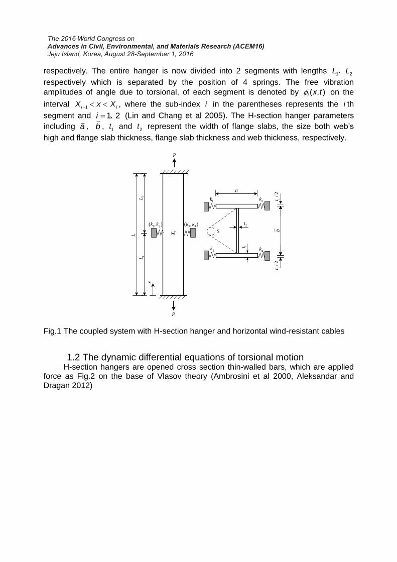
respectively. The entire hanger is now divided into 2 segments with lengths 1 2L L、
respectively which is separated by the position of 4 springs. The free vibration
amplitudes of angle due to torsional, of each segment is denoted by ( , )i x t on the
interval 1i iX x X , where the sub-index i in the parentheses represents the i th
segment and 1 2i 、 (Lin and Chang et al 2005). The H-section hanger parameters
including a,b , 1t and 2t represent the width of flange slabs, the size both web’s
high and flange slab thickness, flange slab thickness and web thickness, respectively.
S
a
b1
/2
t1
/2
t
2t
1t
x
P
P
L
1L2
L
1 2( , )k k 3 4( , )k k
1k 3k
2k4k
1X
Fig.1 The coupled system with H-section hanger and horizontal wind-resistant cables
1.2 The dynamic differential equations of torsional motion H-section hangers are opened cross section thin-walled bars, which are applied
force as Fig.2 on the base of Vlasov theory (Ambrosini et al 2000, Aleksandar and Dragan 2012)

sT T T
TT
x
P
P
If
PT
PP
TT
x
dx
Fig.2 Torsional force in the micro-unit of a H-Section hanger
3
1 3
2
2
( , )
( , )
( , )
( , )
s
is
i
P iP
iI P
T T T
x tT GJ
x
x tT E C
x
PI x tT
A x
x tf I
t
(1)
Where T , sT ,T, PT and If represent total torture, free torture, constraint
torture, axial torture produced by axial force and torsional inertia force of cross-section
respectively[15], G is shear of the modulus of the material, 2.6
EG which E is
Young’s modulus of the material, J is torsional constant of the cross-section,
31
3J bs (Ulstrup 1978, Lee et al 2014) which b s, are the length and width of
cross-section lines respectively, 1E is corrected modulus, 1 21
EE
and is
Poisson ratio, C is warping constant, 3 2
1
24
a b tC ( ,a b are described in Fig.1), P
is axial force and the tensile force is positive, PI is the polar moment inertial of cross-
section, A is the area of cross-section, is the density of the material.
Torsional forces are analyzed in Fig.2, which can write the equilibrium equation of the micro-unit (Ulstrup 1978, Mehrdad 2015) for the H-section hanger:
s Ps P s P I
T T TT T T T T T f
x x x
(2)
Substitution of Eq. (1)into Eq. (2) lead to the torsional equation of motion for
each H-section hanger’s segment:
4 2 2
1 4 2 2
( , ) ( , ) ( , )( ) 0i P i i
P
i i
x t PI x t x tE C GJ I
x A x t
(3)
Where 1E C and GJ are torsional and warping rigidities, respectively.
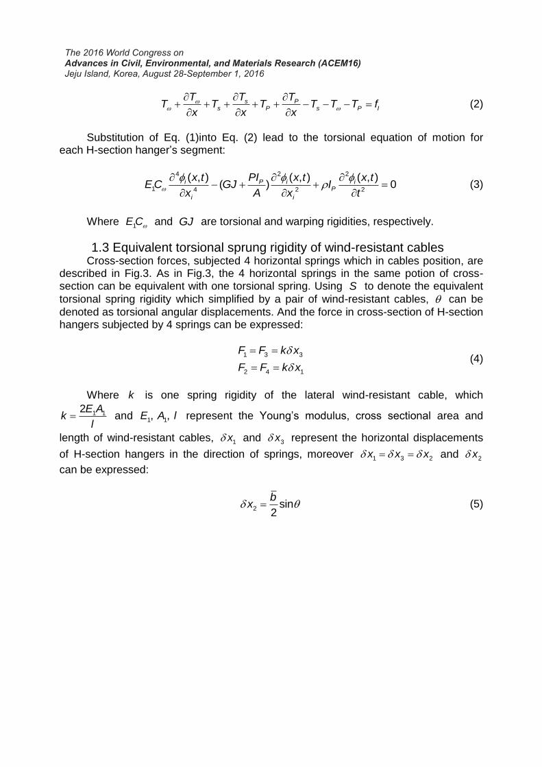
1.3 Equivalent torsional sprung rigidity of wind-resistant cables Cross-section forces, subjected 4 horizontal springs which in cables position, are
described in Fig.3. As in Fig.3, the 4 horizontal springs in the same potion of cross-section can be equivalent with one torsional spring. Using S to denote the equivalent
torsional spring rigidity which simplified by a pair of wind-resistant cables, can be
denoted as torsional angular displacements. And the force in cross-section of H-section hangers subjected by 4 springs can be expressed:
1 3 3
2 4 1
F F k x
F F k x
(4)
Where k is one spring rigidity of the lateral wind-resistant cable, which
1 12E Ak
l and 1 1, , E A l represent the Young’s modulus, cross sectional area and
length of wind-resistant cables, 1x and 3x represent the horizontal displacements
of H-section hangers in the direction of springs, moreover 1 3 2x x x and 2x
can be expressed:
2 sin
2
bx (5)
b
a
1x
2x
S
3x
1 3F k x 3 3F k x
2 1F k x4 1F k x
1F
2F
4F
3F
1t
2t
Fig.3 Cross-sectional torsional force of a H-Section hanger
The equilibrium equation of equivalent torsion can be deduced:
1 3 2 4 2( ) ( ) 2S F F b F F b k x b (6)
Which sin can be derived when is tiny, the equivalent torsional spring
rigidity of wind-resistant cables is derived by simplifying Eq. (6):
2 122
AS E b
l (7)
1.4 Method to find eigensolutions of coupled system Using the separable solutions (Gokdag and Kopmaz 2005, M.Tahmaseb et al
2014), the torsional displacements can be written:
( , ) ( ) i t
i ix t x e (8)
Where ( )i x is thi torsional displacements mode function of each H-section
hanger segment with 1,2i , is circular natural frequencies of coupled system with
a H-section hanger and wind-resistant cables.
( ) sin( ) cos( ) sinh( ) cosh( )i i i i i i i i ix A cl B cl C dl D dl (9)
Where:

1 14 2 4 2
4 42 2( ) ( )4 2 4 2
g g g gc a d a (10)
2 1
4 2
11
PP GJ PII
E C
Aa g
E C
(11)
i i iA B C、 、 and iD are constants associated with thi segment ( 1,2i ).
The “compatibility conditions”, including the torsional displacement, the angle of torsion rate, torsion-bending bi-moment and the total torque of the cross-section, across the equivalent torsional spring of wind-resistant cables can be expressed
1 1 2 1( , ) ( , )D UX t X t (12)
1 1 2 1( , ) ( , )D UX t X t (13)
1 1 1 1 2 1( , ) ( , )D UE C X t E C X t (14)
1 1 1 1 1 2 1 1 2 1 2 1( , ) ( ) ( , ) ( , ) ( , ) ( ) ( , )D D U U UP PPI PIE C X t GJ X t S X t E C X t GJ X t
A A (15)
Where the symbols 1
UX and 1
DX denote the locations immediately above and
below the position 1X , ( , ), ( , ) and ( , )i i ix t x t x t represent the 1,2 and 3 orders
derivative of ( , )i x t .
The “compatibility conditions” from Eq. (9) into Eq. (12) to Eq. (15):
1 1 2
1 1 2
1 1 2
1 1 1 1 1 2
( ) (0)
( ) (0)
( ) (0)
( ) ( ) ( ) (P
L
L
L
PIE C L GJ L S
A
1 2 20) (0) ( ) (0)PPIE C GJ
A
(16)
For the case of the H-section hanger fixed at both ends, the corresponding
boundary conditions can be expressed
1 1 (0, ) 0 (0) 0t (17)
1 1(0, ) 0 (0) 0t (18)
2 2 2 2( , ) 0 ( ) 0L t L (19)
2 2 2 2( , ) 0 ( ) 0L t L (20)
Beginning with those at the left fixed end, Eq. (9), (17) and (18), leads to

1 1 1 1
1 1 1 1
0
0
B D D B
ccA dC C A
d
(21)
Satisfaction of the boundary conditions of Eq. (9) at the right fixed end, Eq. (19)
and (20) require
2 2 2 2 2 2 2 2sin( ) cos( ) sinh( ) cosh( ) 0A cL B cL C dL D dL (22)
2 2 2 2 2 2 2 2cos( ) sin( ) cosh( ) sinh( ) 0A c cL B c cL C d dL D d dL (23)
Which Eq. (9) into Eq. (16) and Eq. (21) to (23) can be expressed in matrix
form as 0R (24)
Where
11 12
21 22
R RR
R R
(25)
11 12
2 2 2 2
2 2 2 2
1 1 1 1
1
21
0 1 0 10 0 0 0
0 0 0 00 1 0
sin( ) cos( ) sinh( ) cosh( )0 0 0 0
ccos( ) c sin( ) cosh( ) sinh( )0 0 0 0
sin( ) cos( ) sinh( ) cosh( )
cos( )
c
R Rdcl cl dl dl
cl cl d dl d dl
cl cl dl dl
c clR
1 1 1
2 2 2 2
1 1 1 1
3 3 3 3
1 1 1 1
22
sin( ) cosh( ) sinh( )
sin( ) cos( ) sinh( ) cosh( )
( )cos( ) ( )sin( ) ( )cosh( ) ( )sinh( )
0 1 0 1
c cl d dl d dl
c cl c cl d dl d dl
c c cl c c cl d d dl d d dl
cR
2 2
3 3
0 0
0 0
( ) ( )
d
c d
c c d d
(26)
Which
1E C L
GJ ( 1 )PPI
LGJ

and is non-dimensional equivalent torsional spring rigidity of wind-resistant
cables, which SL
GJ , is the vector of undermined parameters and
T
1 1 1 1 2 2 2 2A B C D A B C D .
Thus, the existence of non-trivial solutions requires
det 0R (27)
This determinant provides the single equation for the solution of the eigenvalue,
j . The coefficients of the eigenfunctions, ( )x , are obtained by back substitution
into Eq. (26) to get and then Eq. (9) to get each segment of H-section hanger.
2. EXAMPLE OF NUMERICAL CALCULATION RESULTS
2.1 Basic parameters Fig. 4 denotes the prototypical cross-section of H-section hanger in certain steel
arch bridge, and its parameters as in Table 1. Wind-resistant cables are used the
technical specification of 1860MPapkf ,7 15.2mms , which the Young’s modulus
1.95 5MPaE e , Poisson's ratio 0.3 and density 38600kg/m .
1164 1818
500
10
Y
Z
Fig.4 Cross-sectional dimension of a H-Section hanger(mm)
Table 1 Basic parameters of a H-Section hanger
Geometrical parameters Values
H-section hanger parameters /a 0.5m
H-section hanger parameters /b 1.182m
Length of prototype/L 40.212m
Area of prototype/ A 2 22.964 10 m
Moment of inertia in strong axial/ ZI 4 43.751 10 m
Moment of inertia in weak axial / YI 3 47.602 10 m

Polar moment of inertia / PI 3 47.977 10 m
St.Venant’s torsional constant/J 6 42.8065 10 m
Warping constant /C 4 61.310 10 m
Young’s modulus/E 112.0 10 N/m
Shear modulus/G 107.692 10 N/m
Density/ 37850kg/m
Axial force/P 2107KN
2.2 Finite element model Thin shell element of the SHELL63 type is simulated to H-section model, because
of the minimum values of cross-section sizes comparing to length of prototypes. For simulating axial force, the above end is fixed all degrees of freedom and the below end free axial displacement but constrain others degrees, which can greatly imitate the effects of axial force rigidities on torsional natural frequencies.
The type of Link10 element can be simulated to wind-resistant cables which are fixed in the anchorage fields, and the initial tension of wind-resistant cables is imitated by real constant of primary strain. Considering the connection of the flange plates in H-section hanger and wind-resistant cables at the real bridge using rope clip, the connection can be used common nodes including H-section hanger and wind-resistant cables, which neglecting the friction of both attached field.
Fig.5 Finite element model of the coupled system with a H-Section hanger and wind-resistant cables
2.3 The torsional natural frequencies of H-section hanger The coupled system with H-section hanger and wind-resistant cables is degraded
into ordinary H-section hanger when the non-dimensional equivalent torsional spring rigidity of wind-resistant cables 0 . Taking 0 into Eq. (27), the determinant can
be expressed

2 22 (1 cos 2 cosh 2 ) ( sin 2 sinh 2 0)cd cL dL d c cL dL (28)
For verifying the accuracy of Eq. (28) which can be solved by using the standard
Newton-Raphson iterations with the mathematical software MATLAB, table 2 shows the resultant comparisons with finite element method and Ref. [Ulstrup 1978] solutions. The lowest two torsional natural frequencies of three solutions in table 2 have little difference.
Table 2 Comparisons of natural frequencies of the anger(Hz)
Lowest two natural frequencies First order Second order
Theoretical solutions in this paper 2.09 4.93
Formula solutions in Ref. [Ulstrup 1978] 2.12 4.94
Finite element method computation 2.11 5.01
3. FREE TORSIONAL VIBRATION CHARACTERISTICS OF COUPLED SYSTEM
3.1 The effects of wind-resistant cables’ locations and rigidities for torsional natural frequencies
1403K is defined as fundamental value which is non-dimensional rigidities
of equivalent torsional spring for wind-resistant cables, associating with length
100l m , area 2
1 27.8mmA (0.25 times of one steel strand above-mentioned). Fig. 6
shows the lowest two torsional natural frequencies of H-section hanger obtained by the method presented in this research as the non-dimensional stiffness increased and
the locations of wind-resistant cables( 1 /X L ) changed from zero to one, which giving
the finite element method(FEM) computations to further verify theoretical method in this research. Table 3 shows the lowest two maximum torsional natural frequencies of H-section hanger in different values and wind-resistant cables’ locations.

0.0 0.1 0.2 0.3 0.4 0.5 0.6 0.7 0.8 0.9 1.02.0
2.5
3.0
3.5
4.0
4.5
5.0
5.5
6.0
6.5
X1 /L
Theory K
FEM K
Theory 5K
FEM 5K
Theory 10K
FEM 10K
Theory 50K
FEM 50K
First ord
er
tors
ional natu
ral fr
enquencie
s /H
z
0.0 0.1 0.2 0.3 0.4 0.5 0.6 0.7 0.8 0.9 1.04.5
5.0
5.5
6.0
6.5
7.0
7.5
8.0
8.5
9.0
9.5
Second o
rder
tors
ional natu
ral fr
equencie
s/H
z
X1/L
Theory K
FEM K
Theory 5K
FEM 5K
Theory 10K
FEM 10K
Theory 50K
FEM 50K
(a)First order (b)Second order
Fig.6 The lowest two torsional natural frequencies of the coupled system with H-
section hanger and wind-resistant cables in different locations versus
Table 3 The maximum torsional natural frequencies of the first two orders for the hanger(Hz)
First order Second order
0 2.09 4.93 K(1.41 3)e 2.97 5.39
5K(7.05 3)e 4.49 6.87
10K(1.41 4)e 5.28 7.54
50K(7.05 4)e 6.34 8.86
Increased percentage( 50K ) 203.35% 79.66%
As shown in Fig.6 and Table 3, some rules can be deduced: (1) The theoretical solutions are highly anastomosed with finite element method
computations of lowest two torsional natural frequencies, which proves the accuracy and stability of theoretical solutions to solve the torsional natural frequencies of coupled system with H-section hanger and wind-resistant cables. Due to considering the 0.5m length of high strength bolts field at the end of the hanger in finite element model, resulting in the effective length of the hanger decreased partly, the finite element method computations have a little bigger than theoretical solutions.
(2) The lowest two torsional natural frequencies of coupled system are increased gradually along with the values of added. Observing the axial coordinates where
each curve reach the extreme values, the higher torsional natural frequencies are obtained when the wind-resistant cables are in the potion of the biggest node coordinate values of the mode shapes, but the torsional natural frequencies are not affected by the wind-resistant cables when it is located in model node of H-section

hanger (when / =0.5x L , the second order torsional frequencies are common with the
values changed in Fig.6(b)). Hence, considering the first order torsional vibration
control in real engineering, the wind-resistant cables should be installed in the middle length of the hanger, and it should be set in the third or two thirds length of the hanger when the second order torsional vibration need to be restrained.
(3) As is shown in table 3, the first order torsional natural frequencies can be improved to the highest 3.03 times of the original value which don’t have wind-resistant cables attached in hanger, and the second torsional natural frequencies have the highest 1.8 times of its original value, which have highly improvements of lowest two torsional frequencies.
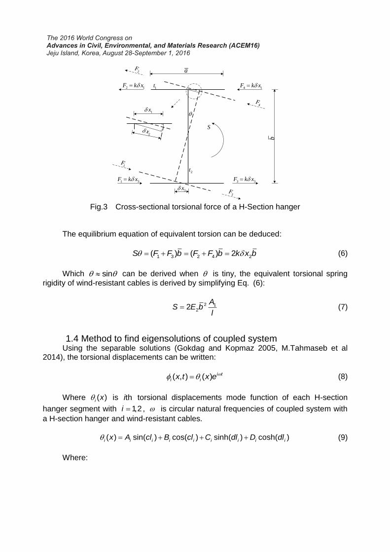
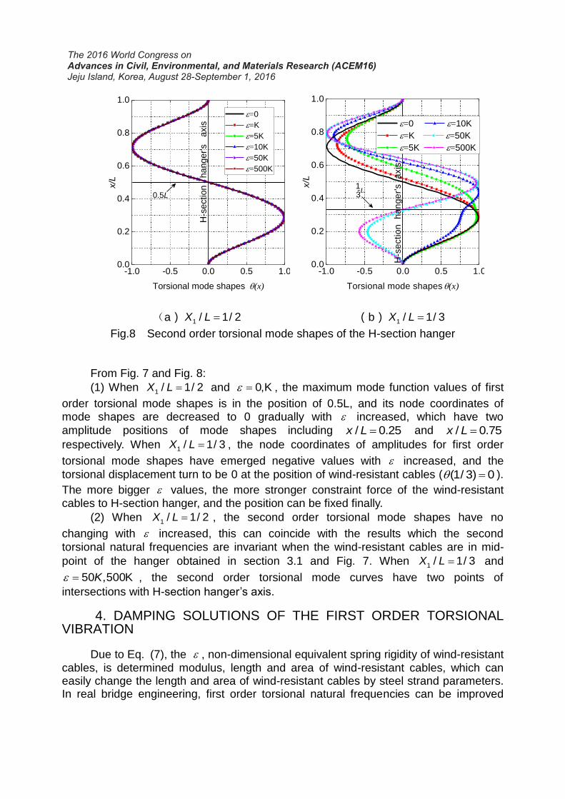
3.2 The effects of wind-resistant cables’ locations and rigidities for torsional mode shapes
Due to the section 3.1, the torsional natural frequencies are improved to the biggest values when the wind-resistant cables are installed in the positions of maximum mode shapes’ node, and the influence rules of lowest two mode shapes with
increased are analyzed when the wind-resistant cables are in the 1/2 and 1/3 lengths of hanger, which are shown in Fig. 7 and Fig. 8.
0.0
0.2
0.4
0.6
0.8
1.0
-1.0 -0.5 0.0 0.5 1.0
Torsional mode shapes (x)
x/L
=0
=K
=5K
=10K
=50K
=500K
0.5L
H-s
ection hanger's a
xis
0.0
0.2
0.4
0.6
0.8
1.0
-1.0 -0.5 0.0 0.5 1.0
H-s
ectio
n
ha
ng
er'
s
axis
Torsional mode shapes (x)
x/L
=0
=K
=5K
=10K
=50K
=500K
L1-3
(a) 1 / 1/ 2X L (b) 1 / 1/ 3X L
Fig.7 First order torsional mode shapes of the H-section hanger
0.0
0.2
0.4
0.6
0.8
1.0
-1.0 -0.5 0.0 0.5 1.0
H-s
ection
h
ange
r's
axis
Torsional mode shapes (x)
x/L
=0
=K
=5K
=10K
=50K
=500K
0.5L
0.0
0.2
0.4
0.6
0.8
1.0
-1.0 -0.5 0.0 0.5 1.0
H-s
ectio
n
ha
ng
er'
s
axis
1
=0 =10K
=K =50K
=5K =500K
Torsional mode shapes (x)
x/L
L-3
(a) 1 / 1/ 2X L (b) 1 / 1/ 3X L
Fig.8 Second order torsional mode shapes of the H-section hanger
From Fig. 7 and Fig. 8:
(1) When 1 / 1/ 2X L and 0,K , the maximum mode function values of first
order torsional mode shapes is in the position of 0.5L, and its node coordinates of mode shapes are decreased to 0 gradually with increased, which have two
amplitude positions of mode shapes including / 0.25x L and / 0.75x L
respectively. When 1 / 1/ 3X L , the node coordinates of amplitudes for first order
torsional mode shapes have emerged negative values with increased, and the
torsional displacement turn to be 0 at the position of wind-resistant cables ( (1/ 3) 0 ).
The more bigger values, the more stronger constraint force of the wind-resistant cables to H-section hanger, and the position can be fixed finally.
(2) When 1 / 1/ 2X L , the second order torsional mode shapes have no
changing with increased, this can coincide with the results which the second
torsional natural frequencies are invariant when the wind-resistant cables are in mid-
point of the hanger obtained in section 3.1 and Fig. 7. When 1 / 1/ 3X L and
50 ,500KK , the second order torsional mode curves have two points of
intersections with H-section hanger’s axis.
4. DAMPING SOLUTIONS OF THE FIRST ORDER TORSIONAL VIBRATION
Due to Eq. (7), the , non-dimensional equivalent spring rigidity of wind-resistant
cables, is determined modulus, length and area of wind-resistant cables, which can easily change the length and area of wind-resistant cables by steel strand parameters. In real bridge engineering, first order torsional natural frequencies can be improved

preferentially, and the best installed positions of wind-resistant cables is in hangers’ mid-point owing to section 3.1. Changing the length and area of wind-resistant cables to make increase, Fig. 9 shows the curves of lowest two torsional natural
frequencies with increased, which also describe the finite element method
computations to compare.
0 5 10 15 20 25 30 352
3
4
5
6
7
Low
est tw
o tors
ional natu
ral fr
equencie
s/H
z
/ ×103
First-order of Theory
First-order of FEM
Second-order of Theory
Second-order of FEM
a
Fig.9 Natural frequencies of the coupled system with a hanger and mid-point wind-resistant cables versus
As is shown in Fig. 9, (1) The curves of the first order torsional natural frequencies are growing rapidly
at the beginning with the high amplification, but latter the tendency become slow and turn into stable finally with increased, which in this time the fundamental torsional
frequencies reach the maximum values. Because the wind-resistant cables are installed in middle hanger, the second order torsional natural frequencies are kept the same values and invariant.
(2) The first torsional natural frequencies will exceed the second after the point of “a” which is a point intersection of two curves with increased. And the first order
torsional natural frequencies keep increasing and the second order emerge first after the point of “a”, which change the maiden orders.
In the above, for damping the first order torsional natural frequencies, the natural frequency value corresponding the point of “a” is treated as the objective torsional frequency, which the corresponding rigidity is treated as objective stiffness. Then backing the objective rigidity into Eq. (7), the requisite length and area of wind-resistant cables can be calculated.
5. CONCLUSIONS
Based on the open thin-walled sections theory of Vlasov and the “compatibility conditions” in the position of wind-resistant cables, the theoretical model of coupled system with a hanger under the fixed-fixed boundaries and horizontal wind-resistant cables is established. The effects and rules of lowest two torsional natural frequencies and its mode shapes are analyzed with the locations and rigidities of wind-resistant cables changed. The following conclusions can be drawn:
(1) The established theoretical approach to solve the torsional natural frequencies of coupled system with a hanger and horizontal wind-resistant cables is verified the greatly accuracy.
(2) For improving first order torsional natural frequencies of H-section hanger, the wind-resistant cables should be installed in the middle length of hanger, which in this position the fundamental torsional frequencies increase rapidly at the beginning, and the incremental trend is slow gradually, which the hanger is fixed in the position of wind-resistant cables and turned to be two independent segments completely with the torsional rigidity of wind-resistant cables increased finally. And the maximum value of fundamental torsional natural frequency for H-section hanger in this numerical results is 3.03 times of its original value. Due to the special position which in mid-point of H-section hanger of the wind-resistant cables, the first order torsional frequencies surpass the second order when the equivalent torsional rigidities of wind-resistant cables are greater than a certain threshold, which can inverse the wind-resistant cables’ parameters according to objective torsional frequency which is the intersection value of the first and second order frequencies’ curves.
(3) With the invariant wind-resistant cables rigidity, the best second order torsional frequencies can be obtained when the cables are installed in 1/3 or 2/3 length of hanger. And there are two points with hanger’s axis to the second order torsional mode shapes with the wind-resistant cables rigidities increased. The maximum value of second torsional natural frequency for H-section hanger in this numerical results is 1.80 times of its original value.
REFERENCES
Keller P, Higgins C, Lovejoy S.C. (2015), “Evaluation of torsional vibrations in steel truss bridge members.” Journal of Bridge Engineering-ASCE, Vol, 20(9): 04014102.
Chen Z.Q., Liu M.G., Hua X.G., et al. (2012), “Flutter, galloping, and vortex-induced vibrations of H-Section hangers.” Journal of Bridge Engineering-ASCE, Vol 17(3): 500-508.
Prasad S., O'neil T. (1984), “Vlasov theory of electrostatic modes in a finite length electron column.” Physics of Fluids, Vol, 27(1): 206-213.
Matsumoto M., Shirato H., Mizuno K., et al. (2008), “Flutter characteristics of h-shaped cylinders with various side-ratios and comparisons with characteristics of rectangular cylinders.” Journal of Wind Engineering and Industrial Aerodynamics, Vol, 96(6): 963-970.
Matsumoto M., Shirato H., Hirai S. (1992), “Torsional flutter mechanism of 2-d h-shaped cylinders and effect of flow turbulence.” Journal of Wind Engineering and Industrial Aerodynamics, Vol, 41(1): 687-698.
Maher F.J., Wittig L.E. (1980), “Aerodynamic response of long H-sections.” J. Struct. Div., Vol, 106(1): 183-198.
Ulstrup C.C. (1980), “Aerodynamic lessons learned from individual bridge members.” Annals of the New York Academy of Sciences, Vol, 352(1): 265-281.
Huang Z.H. Nicholas P.J. (2011), “Damping_of_taut-cable_systems_effects_of linear elastic spring support.” Journal of Engineering Mechanics, Vol, 137(7): 512-518.
Zhou H.J., Yang X., Sun L.M., et al. (2015), “Free vibrations of a two-cable network with near-support dampers and a cross-link.” Structural Control and Health Monitoring, Vol, 22(9): 1173-1192.
Javaid A, Cheng S. H. (2013), “Effect of cross-link stiffness on the in-plane free vibration behavior of a two-cable network.” Engineering Structures, Vol, 52: 570-580.
Ruscheweyh H., Hortmanns M., Schnakenberg C. (1996), “Vortex-excited vibrations and galloping of slender elements.” Journal of Wind Engineering and Industrial Aerodynamics, Vol, 65(1): 347-352.
Lin H.P., Chang S.C. (2005), “Free vibration analysis of multi-span beams with intermediate flexible constraints.” Journal of Sound and Vibration, Vol, 281(1): 155-169.
Ambrosini R.D., Riera J.D., Danesi R.F. (2000), “Modified Vlasov theory for dynamic analysis of thin-walled and variable open section beams.” Engineering Structures, Vol, 22(8): 890-900.
Aleksandar P., Dragan L. (2012), “Flexural-torsional vibration analysis of axially loaded thin-walled beam.” Journal of the Brazilian Society of Mechanical Sciences and Engineering, Vol, 34(3): 262-268.
Ulstrup C.C. (1978), “Natural frequencies of axially loaded bridge members.” Journal of the Structural Division, Vol, 104(2): 849-857.
Lee J.K., Jeong S., Lee J. (2014), “Natural frequencies for flexural and torsional vibrations of beams on pasternak foundation.” Soils and Foundations, Vol, 54(6): 1202-1211.
Mehrdad M. (2015), “New analytical approach for determination of flexural, axial and torsional natural frequencies of beams.” Structural Engineering and Mechanics, Vol, 55(3): 655-674.
Gokdag H., Kopmaz O. (2005), “Coupled bending and torsional vibration of a beam with in-span and tip attachments.” Journal of Sound and Vibration, Vol, 287(3): 591-
610. M.Tahmaseb T.K., Supun J., Seyed M.H. (2014), “On the flexural-torsional vibration
and stability of beams subjected to axial load and end moment.” Shock and Vibration, Vol, 2014:153532 (10).