free standing workstation jib cranes - spanco can custom design ... systems can be linked to a...
TRANSCRIPT

126
Counterweight BasesPortable counterweight bases are available for freestandingworkstation jibs, which allows the jib to be moved by fork liftanywhere in the facility. • Available in capacities to 500 lbs.
and spans to 16 ft., depending on combination of span and capacity. • Portable cranes eliminate the need for unnecessary hoisting
equipment. One unit can service multiple areas.
Cost-effective Solutions For Lifting and Moving
Heavy Material
ENCLOSED TRACK WORKSTATION JIB CRANES
FREESTANDING
• SPANCO can custom design and manufacture jib cranes for any application.
• SPANCO freestanding 360° rotation workstation jib cranes are an ideal, lightweight ergonomic solution for smaller capacity loads up to 1,000 lbs., spans to 16 ft. Lightweight boom design makes the jib easier to rotate and position.
FREE STANDING
WORKSTATIONJIB CRANES

127
WALL MOUNTED
• SPANCO’s wall mounted200° rotation enclosed trackworkstation jibcranes can be tie rodsupported for the lowest cost or compression braced for maximumhead room.
• Tie rod supported models can be fabricated with trussed track for spansup to 34 ft.
WARNING:Jib cranes should not be hung from any existing building structure without first consulting a qualified architect or engi-neer for the purpose of determining if the structure is adequate. Severe bodily injury and property damage can resultif this procedure is not followed.
WALL MOUNTEDWORKSTATIONJIB CRANES

128
standard bridge lengths to 34'custom designs available
standard capacities to 2 tons
trolley clevis height above floor determined by ceiling structure
Pre-engineered system kit. Everything
supplied excepthoist and sway
bracing.standard runway lengths to 103'
SPANCO ceiling mounted workstation bridge cranes provide ideal, cost effectivematerial handling solutions…
• If work floor space is limited: Ceiling mounted systems provide infinite coverage without interfering supportcolumns. Systems can be linked to a monorail or another bridge crane using crane interlock sections.
• Easy, ergonomic movement: An operator pushing a 1000 lb. load, will experience a force of approximately 10 lb.to begin moving the load and 8 lb. to continue moving the load (100 to 1 ratio). Manual cranes also operatemore quickly than motorized cranes making them ideal for fast paced work environments.
However, if the application requires moving heavier loads up to two tons or bridge travel over an inaccessible area,then a motorized system can be used efficiently. SPANCO can provide motorized systems in 1,000, 2,000 and 4,000 lb. capacities.
Ceiling mounted systems are supported by the building structure. A qualified architect or engineer should be consult-ed to determine the adequacy of the building structure intended to support the crane system.
SOLVING YOUR MATERIAL HANDLING PROBLEMS WITH CEILING MOUNTED WORKSTATION BRIDGE CRANES
CEILING MOUNTED
WORKSTATIONBRIDGE CRANES
AvailableCapacities (lbs)
250500
1,0002,0004,000

129
DESIGN FACTORS• Nameplate bridge capacity represents the rated load on the hoist hook. The load rating of a hoist shall not exceed the bridge rating. SPANCO’s design includes an allowance of 15% of nameplate capacity for dead weight of the trol-ley and hoist. An additional allowance of 25% of nameplate capacity is also included for impact.
SERVICE FACTORAll SPANCO workstation cranes are designed for frequent usage (heavy service) as defined:
• System or equipment is used where operational time is up to 100% of the work period and lifted load is at 50% orbelow rated capacity.
• System or equipment is used where operational time is less than 50% of work period and lifted load is greater than50% of rated capacity.
• Applications involving vacuums, magnets, or other high impact lifters are considered severe usage (continuousservice) and require special design considerations. Please contact factory for special design pricing.
• Consult factory for usage other than moderate and all instances of high cycle rates or high impact applications suchas high speed air or electric hoists, vacuum lifters, or magnets. FACTORY MUST APPROVE ALL SUCHAPPLICATIONS.
DETERMINING CAPACITY, WIDTH, LENGTH, AND HEIGHT
• Capacity: Load weights should be predetermined in order to avoid buying extra, unneeded capacity. Bridgedead weight will add more weight to the load the operator will be moving.
• Width: Bridge span is the length of a bridge between centers of two runways. SPANCO’s standard design pro-vides a standard bridge overhang of 12 in. on each end beyond the runway centerline. Bridge length is theoverall length.
• Length: Runway length is determined by the length of a specific area requiring coverage. Runways are support-ed on maximum 20, 25, or 30 ft. support centers. Plain track runways are supported every 6 ft. for 400, 500,600, and 900 series and every 9 ft. for 700 series.
• Height: In order to attain minimal resistance, it is recommended that the trolley clevis height be kept as low aspossible, with practical consideration given to minimum headroom requirements. Height is measured from thefloor to the trolley clevis from which a hoist is suspended.
130
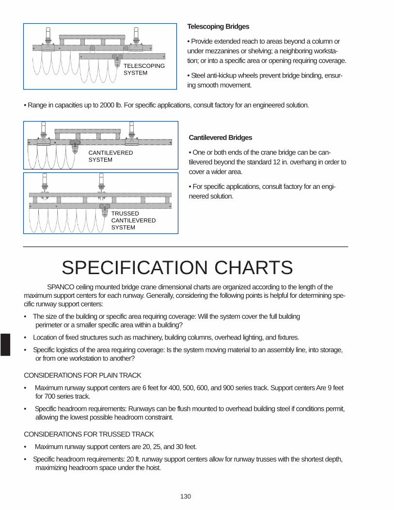
Cantilevered Bridges
• One or both ends of the crane bridge can be can-tilevered beyond the standard 12 in. overhang in order tocover a wider area.
• For specific applications, consult factory for an engi-neered solution.
SPANCO ceiling mounted bridge crane dimensional charts are organized according to the length of themaximum support centers for each runway. Generally, considering the following points is helpful for determining spe-cific runway support centers:
• The size of the building or specific area requiring coverage: Will the system cover the full building perimeter or a smaller specific area within a building?
• Location of fixed structures such as machinery, building columns, overhead lighting, and fixtures.
• Specific logistics of the area requiring coverage: Is the system moving material to an assembly line, into storage,or from one workstation to another?
CONSIDERATIONS FOR PLAIN TRACK
• Maximum runway support centers are 6 feet for 400, 500, 600, and 900 series track. Support centers Are 9 feetfor 700 series track.
• Specific headroom requirements: Runways can be flush mounted to overhead building steel if conditions permit,allowing the lowest possible headroom constraint.
CONSIDERATIONS FOR TRUSSED TRACK
• Maximum runway support centers are 20, 25, and 30 feet.
• Specific headroom requirements: 20 ft. runway support centers allow for runway trusses with the shortest depth,maximizing headroom space under the hoist.
SPECIFICATION CHARTS
Telescoping Bridges
• Provide extended reach to areas beyond a column orunder mezzanines or shelving; a neighboring worksta-tion; or into a specific area or opening requiring coverage.
• Steel anti-kickup wheels prevent bridge binding, ensur-ing smooth movement.
• Range in capacities up to 2000 lb. For specific applications, consult factory for an engineered solution.
TRUSSEDCANTILEVERED SYSTEM
CANTILEVERED SYSTEM
TELESCOPINGSYSTEM

131
CEILING MOUNTED WORKSTATION BRIDGE CRANES
RUNWAY TRUSS ORPLAINTRACK, ENDTRUCK, & TRUSSHANGERS
BRIDGE (TRUSS TYPE SHOWN) ROOF BEAM OR OTHER STRUCTURE (BYOTHERS) SPECIFY WHEN ORDERING
BRIDGE SPAN (BS)
BRIDGE LENGTH (BL)
CLEAR SPAN (CS)
B/R
ASS
EMBL
Y(B
RH
)
BRIDGE HOOK APPROACH 1 (BHA1)
BRIDGE HOOK APPROACH 2 (BHA 2)
BRIDGE FESTOON
RUNWAY LENGTH (RL)
C = TROLLEY DIMENSION (bottom of the bridge to trolley clevis) BH = BRIDGE HEIGHT RH = RUNWAY HEIGHT
STANDARD UP TO 103'
(LONGER RUNWAYS AVAILABLE)
END STOPS (OR TRACK SPLICE @LONGER RUNWAYS)
END TRUCKTROLLEY (DIMENSIONS BASED ON STANDARD) (C)
RUNWAY FESTOON CONTINUES TO BRIDGEFESTOON & HOIST
BRIDGE (TRUSS TYPE SHOWN)
B/R
ASSE
MBL
Y(B
RH
) 1' 0"
1' 0" MAXIMUMCANTILEVER
RUNWAY LENGTH (RL) STANDARD UP TO 103'
(LONGER RUNWAYS AVAILABLE)
END STOPS (ORTRACK SPLICE @ LONGER RUNWAYS)
END TRUCKTROLLEY (DIMENSIONS BASED ON STANDARD) (C)
RUNWAY FESTOON CONTINUES TO BRIDGE FESTOON & HOIST
BRIDGE (TRUSS TYPE SHOWN) SPLICE PLATES @ LONGER RUNWAYS
SUPPORT CENTERS (S/C)
B/R
ASSE
MBL
Y(B
RH
) 1' - 6" 1' - 6"
1' - 2
3/1
6"(S
TD)
1' - 5
3/8
"(S
TD)
TRO
LLEY
CLE
VIS
HT.
(TC
H)
RUNWAY HOOK APPROACH (RHA)
RUNWAY HOOK APPROACH (RHA)
RUNWAY HOOK APPROACH (RHA)
RUNWAY TRUSS
FESTOON TRACK EXTENSION (FTE)
FESTOON TRACK EXTENSION (FTE)
PLAIN TRACK RUNWAY
TRUSSED TRACK RUNWAY4' - 0" MAXIMUMCANTILEVER
1' 0"
TRO
LLEY
CLE
VIS
HT.
(TC
H)
TO POWERSUPPLY
TRO
LLEY
CLE
VIS
HT.
(TC
H)
2" SIDE CLEARANCE
(BH)
2" SIDE CLEARANCE
12" TO 54" (STANDARD FESTOON TRACK EXTENSIONS) SPECIAL LENGTHS AVAILABLE
(RH)
FSA
RUNWAY HOOK APPROACH (RHA)
MAXIMUM SUPPORT CENTERS (S/C)
TO POWERSUPPLY
TROLLEY (DIMENSIONSBASED ON STANDARD) (C)
™

132
SYSTEM SPECIFICATIONS FOR CEILING MOUNTED KITS
SPANCO Ceiling Mounted Workstation Bridge Crane kits include:
BRIDGE KITS1. Plain bridge, tube reinforced bridge, or trussed bridge as required2. Hoist trolley3. Bridge end stops4. Festoon cable with trolleys5. End trucks
RUNWAY KITS1. Hangers2. Runway end stops3. Festoon cables with trolleys4. Standard festoon track extension5. Plain or trussed runways
• Ceiling mounted system kits include appropriate number of hanger rods, hangers, adjustable beam clamps, and track supportbrackets.
• Ceiling mounted system kits do not include hoist or required sway bracing.• All ceiling mounted systems must be properly braced to existing structure using proper sway bracing. To achieve desired rigidi-
ty for specific application, SPANCO recommends consulting a professional architect or engineer in your local area to satisfyall codes and ordinances.
• Dimensions shown are approximate and subject to change without notice. All catalog dimensions are developed using stan-dard components for the spans and capacities required. Substitution of optional trolleys or other components will affect cer-tain dimensions. If specific clearances are required, specify at time of order.
CUSTOMER:TRACK SERIES: CAPACITY:NUMBER OF UNITS:TROLLEY CLEVIS HT. (TCH):CEILING HEIGHT:BRIDGE / RUNWAYMODEL NUMBER:BRIDGE LENGTH (BL):CLEAR SPAN (CS):OVERALL RUNWAY LENGTH (RL):
STANDARD SUPPORT CENTERS (S/C):RUNWAY SUPPORT CENTERS (S/C1):RUNWAY SUPPORT CENTERS (S/C2):RUNWAY SUPPORT CENTERS (S/C3):RUNWAY SUPPORT CENTERS (S/C4):RUNWAY SUPPORT CENTERS (S/C5):HANGER ROD LENGTH:ELECTRICAL REQUIREMENTS:FESTOON TRACK EXTENSION (FTE):FESTOON CABLE LENGTH (FCL):
BRIDGE CRANE KITS & CEILING MOUNTED KITS
Applies to all runway lengths up to 103'
CEILING MOUNTED WORKSTATION BRIDGE CRANESEND APPROACH
™

133
SOLVING YOUR MATERIAL HANDLING PROBLEMS WITHSTAND ALONE WORKSTATION BRIDGE CRANES
SPANCO stand alone workstation bridge cranes provide ideal, cost effective material handling solutions…
If you rent your building: Stand alone systems do not become a permanent part of a structure onceinstalled, allowing for relocation.
Your structural building support is inadequate for an overhead ceiling mounted crane: The onlymounting requirement is a standard concrete building floor (in most cases).
A specific area needs coverage, however you don’t want to tie up your existing overhead crane:Stand alone SPANCO workstation bridge crane systems can provide coverage for individual work areas.
STAND ALONEWORKSTATIONBRIDGE CRANES
standard bridge lengths to 34'custom designs available
standard capacities to 2 tons
standard heights 10' - 12' - 14'
standard runway lengths to 124'
AvailableCapacities (lbs)
250500
1,0002,0004,000
Pre-engineered system kit. Everything
supplied excepthoist and sway
bracing.

134
STAND ALONE WORKSTATION BRIDGE CRANES
DETERMINING CAPACITY, WIDTH, LENGTH, AND HEIGHT
• Capacity: Load weights should be predetermined in order to avoid buying extra, unneeded capacity.Bridge dead weight will add more weight to the load the operator will be moving.
• Width: Bridge span is the length of a bridge between centers of two runways. SPANCO’s standard designprovides a standard bridge overhang of 12 in. on each end beyond the runway centerline. Bridge lengthis the overall length.
• Length: Runway length is determined by the length of a specific area requiring coverage. Runways aresupported on maximum 20, 25, or 30 ft. support centers.
• Height: In order to attain minimal resistance, it is recommended that the trolley clevis height be kept aslow as possible, with practical consideration given to minimum headroom requirements. Height is meas-ured from the floor to the trolley clevis from which a hoist is suspended. The specification charts give theoverall height of each system.
HEADER LENGTH (HL)
RUNWAYTRUSS,
END TRUCK, & TRUSS
HANGERS
1' - 0"
2"
TROLLEY (DIMENSIONSBASED ON STANDARD)
BRIDGE (TRUSS TYPE SHOWN)
BRIDGE FESTOON
BRIDGE SPAN (BS)
BRIDGE LENGTH (BL)COLUMN CENTERS (C/C)
CLEAR SPAN (CS)
OVERALL WIDTH (OAW) AT BASE
SLAB OR FOUNDATION DESIGN NOTBY SPANCO
B/R
ASS
EMBL
Y(B
RH
)
HEA
DER
(HD
R)
OVE
RAL
LH
EIG
HT
(OAH
)
TRO
LLEY
CLE
VIS
HT.
(TC
H)
COLUMN
1' - 0"
2"
COLUMN
BHA1 BHA2

OVERALL RUNWAY LENGTH(RL):
STANDARD SUPPORT CENTERS(S/C):
RUNWAY SUPPORT CENTERS (S/C1):
RUNWAY SUPPORT CENTERS (S/C2):
RUNWAY SUPPORT CENTERS (S/C3):
RUNWAY SUPPORT CENTERS (S/C4):
RUNWAY SUPPORT CENTERS (S/C5):
OVERALL HEIGHT (OAH):
ELECTRICAL REQMNTS:
FESTOON TRACK EXTENSION (FTE):
FESTOON CABLE LENGTH (FCL):
CUSTOMER:
TRACK SERIES: CAPACITY:
NUMBER OF UNITS:
TROLLEY CLEVIS HT. (TCH):
BRIDGE / RUNWAY:
MODEL NUMBER:
RUNWAY SUPPORT ASSEMBLY:
MODEL NUMBER:
BRIDGE LENGTH(BL):
CLEAR SPAN (CS):
OVERALL WIDTH (OAW):
135
COLUMN
RUNWAY LENGTH (RL) STANDARD UP TO 103'
(LONGER RUNWAYSAVAILABLE)
END STOPS (OR TRACKSPLICE @LONGER
RUNWAYS)
END TRUCK
TROLLEY (DIMENSIONSBASED ON STANDARD)
RUNWAY FESTOONTO POWERSUPPLY
RUNWAY TRUSS
CONTINUES TO BRIDGEFESTOON & HOIST
BRIDGE (TRUSS TYPE SHOWN)
RUNWAY SUPPORT CENTERS (SEE CHARTS)SPECIFY S/C1, S/C2, S/C3, ETC. FOR CUSTOM PRODUCTS
COLUMNSLAB OR
FOUNDATION DESIGNNOT BY SPANCO
12" TO 54" (STANDARD FESTOON TRACK EXTENSIONS, SPECIAL LENGTHS AVAILABLE)
SPLICE PLATES@ LONGERRUNWAYS
COLUMN SUPPORT CENTERS (S/C)
B/R
ASSE
MBL
Y(B
RH)
HEA
DER
(HD
R) 1' - 6"
1' - 6"
4' - 0" MAXIMUMCANTILEVER
FESTOON TRACK EXTENSION (FTE)
S/C1, S/C2, S/C3, S/C4, S/C5, ETC.
SPECIFY IF NON-STANDARD
TRO
LLEY
CLE
VIS
HT.
(TC
H)
RHARHA
FTE
BRIDGE CRANE KITS & STAND ALONE KITS

136
CO
L. +
6"
CO
L. +
5"
CO
L. +
3"
CO
LUM
N
CO
LUM
N
CO
LUM
N
CO
L. +
5"
CO
L. +
3"
CO
L. +
2"
BASE DETAIL “A”125# CAP. w/ 3" COLS. (10', 12', 14' TCH)250# CAP. w/ 3" COLS. (10', 12', 14' TCH)500# CAP. w/ 3" COLS. (10' TCH)
BASE DETAIL “B”250# CAP. w/ 4" COLS. (10', 12', 14' TCH)500# CAP. w/ 4" COLS. (10', 12', 14' TCH)
1000# CAP. w/4" COLS. (10', 12' TCH)4000# CAP. w/7" COLS. (10', 12',14' TCH)
BASE DETAIL “C”1000# CAP. w/5" COLS. (14 TCH)2000# CAP. w/5" COLS. (10', 12',14' TCH)
SYSTEM SPECIFICATIONS FOR STAND ALONE KITS
SPANCO Stand Alone Workstation Bridge Crane kits include:1. Plain, reinforced, or trussed crane bridge with end trucks2. Hoist trolley3. Runway support columns4. Runway trusses5. Header beams6. Hanger clamps, end stops, and flat wire electrification festooning system for both runway and bridge
SYSTEM REQUIREMENTS: • Bracing to building steel for lateral and longitudinal stability required (furnished by others). To achieve desired rigidity for an application,
SPANCO recommends consulting a professional engineer in your area to satisfy all codes and ordinances.• Four 3/4" diameter anchor bolts required per column (furnished by others).• Hoist supplied by others.
OTHER SYSTEM CONSIDERATIONS:• Per SPANCO’s design standard, at maximum load conditions, deflection is restricted to approximately 1/450 of span. SPANCO candesign to meet any higher customer standard.• SPANCO Stand Alone Workstations are for frequent usage in a normal industrial environment.• Maximum support spacing for trussed track at rated capacity shall not exceed:
400 Series = 20' or 25' 700 Series = 20', 25', or 30'500 Series = 20', 25', or 30' 900 Series = 20' or 25'600 Series = 20', 25', or 30'
• Dimensions shown are approximate and are subject to change without notice. All catalog dimensions are developed using standardcomponents for the spans and capacities required. Substitution of optional trolleys or other components will affect certain dimensions ifspecific clearances are required at the time of order.
COLUMN DETAILS
Applies to all runway lengths up to 108'
STAND ALONE WORKSTATION BRIDGE CRANESEND APPROACH

200
Free standing jib cranes are available in three basic styles to suitspecific applications: base plate mounted, foundation mounted, andsleeve insert mounted. 360° rotational capability can maximize theutilization of any work area.No additional support is needed other than the specified rein-
forced concrete foundation.
FREE STANDING JIB CRANES• 360° rotation.• Allows for electrified, motor driven, powered rotation through various collector ring assemblies.• The boom or I-beam is designed to meet all specifications utilizing a 25% factor of rated load for impact and 15% of
rated load for hoist and trolley weight.• The pipe mast or column is designed to give maximum strength and minimum deflection to resist bending, buckling,
and crushing as well as wear by the trunnion roller assembly.• The top bearing assembly utilizes a Timken tapered roller bearing provided with a grease fitting for proper lubrication.• The bearings are designed for a 5000 hour, B-10 design life.
FREE STANDINGJIB CRANES
Base Plate Mounted • Utilizes a hexagonal base plate reinforced with six knee braces equally spaced
on the circumference of the mast.• The base plate assembly is secured by means of anchor bolts to a prescribed
reinforced concrete foundation, with the number of anchor bolts varying withthe capacity of the crane.
• Six bolts are used for columns less than 16" in diameter and 12 bolts forcolumns 16" in diameter and greater.
100 SERIES
standard under boom heights from 8 to 20 ft.,up to 40 ft. on request
standard capacities to 5 tons, special capacities to 15 tons
standard spans to 20 ft.up to 60 ft. on request

201
Foundation Mounted • Utilizes a square steel plate which is welded to the bottom of the
column. • The plate positions and levels the mast by anchoring it to a first-pour
concrete footing.• A second-pour foundation of reinforced concrete supports the mast.
Makes complete use of the work floor area and can be used inapplications where a base plate could hamper floor activity.
101 SERIESstandard spans to 20 ft.up to 60 ft. on request
standard under boom heights from 8 to 20 ft.,up to 40 ft. on request
standard capacities to 5 tons, special capacities to 15 tons
102 SERIESstandard spans to 20 ft.up to 60 ft. on request
standard under boom heights from 8 to 20 ft.,up to 40 ft. on request
standard capacities to 5 tons, special capacities to 15 tons
Sleeve Insert Mounted • 360° rotation.• Utilizes a square steel plate which is welded to the
bottom of the sleeve.• Allows for relocation of the mast.• The plate positions and levels the sleeve by anchor-
ing it to a first-pour concrete footing.• A second-pour foundation of reinforced concrete
supports the sleeve.• The mast is thenplaced into the sleeve where it is
leveled by wedges and welded in place. 102 seriescan be relocated without damaging the mast.*
• Makes complete use of the work floor area and canbe used in applications where a base plate couldhamper floor activity.
*New sleeve and foundation would be required.

202
• SPANCO mast mounted jib cranes offer a lower cost alternativeto free standing jib cranes.
• Full 360° rotation, without requiring a large mounting foundation(which can cost more than the crane).
• Requires top and bottom support of the mast to building floorand overhead building steel.
• Power rotation is available on all models.
WARNING:Jib cranes should not be hung from any existing building structure without firstconsulting a qualified architect or engineer for the purpose of determining if thestructure is adequate. Severe bodily injury and property damage can result ifthis procedure is not followed.
MAST JIB CRANES
Drop Cantilever
• Identical to the Series 200 with theaddition of side-plate connections whichallow the boom to be mounted perma-nently at any specified height on themast.
• Provides clearance for overheadobstructions above the boom, belowthe top of the mast.
201 SERIES
standard capacities to 5 tonsGreater spans, heights, and
capacities on request
standard spans to 20 ft.
standardheight to
20 ft.
MASTJIB CRANES
Full Cantilever
• Utilizes an I-beam for the boom and an H-beam for the column.• Two types of bearing arrangements:
1. Aself-aligning spherical bearing is used on the top bearing assem-bly.2. Abronze bearing and bronze thrust washer are used on the bottomassembly.
• Both bearing assemblies are provided with grease fittings to providelubrication and to aid rotation.
• The boom is mounted at the top of the mast in order to provide maxi-mum underboom clearance.
200 SERIES
standard capacities to 5 tonsGreater spans, heights, and
capacities on request
standard spans to 20 ft.
standardheight to
20 ft.

203
WALLMOUNTEDJIB CRANESCost-effective Solutions For Lifting and Moving
Heavy Material
Wall Cantilever Kits (shown above)Customers can fabricate their own Wall Cantilever Jib Crane using the hinge
components supplied by SPANCO. All hardware for bolting the hinges tothe jib are supplied.
standardcapacities to
5 tons,higher capaci-ties available
standard spans to 30 ft. (longer spans available)
WALL MOUNTED JIB CRANES
Wall Cantilever Jib Cranes • 200° rotation.• Offers greatest potential underboom clearance
because it can be installed more closely to the ceil-ing than other wall mounted styles.
• Two connection types:1. A welded connection is used in most capacity and
boom spans.2. A bolted connection is used for larger spans and
capacities because of shipping considerations. Stiffeners are welded to the mast at the point
where the wall brackets are connected to stiffen theweb of the I-beam.
• Powered rotation is available on all models.• Hardware for mounting to wall or column supplied
by others.
300 SERIES

204
Wall Bracket Tie Rod Supported Jib Cranes • 200° degree rotation.• Utilizes a standard I-beam boom, a tie rod threaded
at both ends, a fabricated beam bracket, and twowall brackets; one for the tie rod and one for theboom.
• Allows maximum usage of the work area, includingwork close to the existing structure, because thereare no supporting components under the boom.
• This design is the most economical style of jib crane,provided overhead clearance or building columnstrength is not a limiting factor.
• Hardware for mounting to wall or column supplied byothers.
standard capacities to5 tons
standard spans to 30 ft.(longer spans available)
WALL BRACKET KITSInclude all componentsexcept the I-beam, tie rod,and mounting hardwarewhich if preferred, can bepurchased locally.
Wall Bracket Connection• Top and bottom wall brackets utilize a formed steel
channel, with two bronze bushings, bronze thrustwashers, and formed tie rod clevises.
• All bolted connections are in double shear.• All swivel connections utilize bronze bushings and grease
fittings to ease rotation, promoting long life and low maintenance.
WARNINGS FOR 300 AND 301 SERIES JIBS This equipment is not, in any way, designed for the lifting, supporting, or transporting humans. Failure to follow the specified load and mounting limitations canresult in serious bodily injury and/or property damage.
Jib cranes should not be hung from any existing building structure without first consulting a qualified architect or engineer for the purpose of determining if the structure is adequate. Severe bodily injury and property damage can result if this procedure is not followed.
301 SERIES

205
ARTICULATING JIB CRANESFree Standing
Bridge and CeilingMounted
• Articulating jib cranes can move loads around corners and columns,reach into machinery and containers and service an area from close tothe pivot point to the end of the boom for 360° of operation. Capacitiesfrom 150 to 2,000 lbs., spans to 16 ft.
• Articulating jibs can be floor, wall, ceiling, or bridge crane mounted tobest suit your application.
• Free standing and ceiling mounted series offer 360° rotation with options to internally pipe compressed air, vacuum or electrification to any device supported onthe end of the boom.
• SPANCO’s bridge mountedarticulating jib design offersmore headroom than thoseby other manufacturers.
• Bridge mounted jibs cansupport nearly any type ofmanipulator, balancer,or hoist.
ARTICULATINGJIB CRANES
206
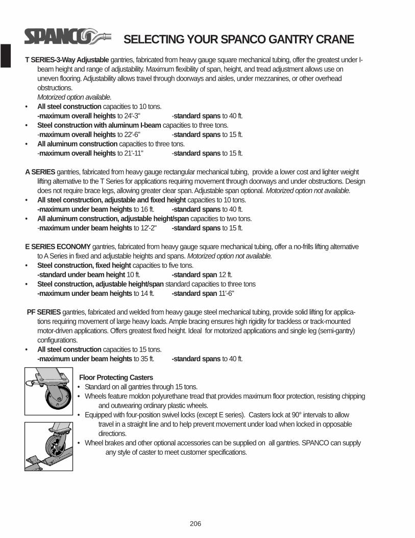
SELECTING YOUR SPANCO GANTRY CRANET SERIES-3-Way Adjustable gantries, fabricated from heavy gauge square mechanical tubing, offer the greatest under I-
beam height and range of adjustability. Maximum flexibility of span, height, and tread adjustment allows use onuneven flooring. Adjustability allows travel through doorways and aisles, under mezzanines, or other overheadobstructions. Motorized option available.
• All steel construction capacities to 10 tons.-maximum overall heights to 24'-3" -standard spans to 40 ft.
• Steel construction with aluminum I-beam capacities to three tons.-maximum overall heights to 22'-6" -standard spans to 15 ft.
• All aluminum construction capacities to three tons.-maximum overall heights to 21'-11" -standard spans to 15 ft.
A SERIES gantries, fabricated from heavy gauge rectangular mechanical tubing, provide a lower cost and lighter weightlifting alternative to the T Series for applications requiring movement through doorways and under obstructions. Designdoes not require brace legs, allowing greater clear span. Adjustable span optional. Motorized option not available.
• All steel construction, adjustable and fixed height capacities to 10 tons.-maximum under beam heights to 16 ft. -standard spans to 40 ft.
• All aluminum construction, adjustable height/span capacities to two tons.-maximum under beam heights to 12'-2" -standard spans to 15 ft.
E SERIES ECONOMY gantries, fabricated from heavy gauge square mechanical tubing, offer a no-frills lifting alternativeto ASeries in fixed and adjustable heights and spans. Motorized option not available.
• Steel construction, fixed height capacities to five tons.-standard under beam height 10 ft. -standard span 12 ft.
• Steel construction, adjustable height/span standard capacities to three tons-maximum under beam heights to 14 ft. -standard span 11'-6"
PF SERIES gantries, fabricated and welded from heavy gauge steel mechanical tubing, provide solid lifting for applica-tions requiring movement of large heavy loads. Ample bracing ensures high rigidity for trackless or track-mountedmotor-driven applications. Offers greatest fixed height. Ideal for motorized applications and single leg (semi-gantry)configurations.
• All steel construction capacities to 15 tons.-maximum under beam heights to 35 ft. -standard spans to 40 ft.
Floor Protecting Casters• Standard on all gantries through 15 tons.• Wheels feature moldon polyurethane tread that provides maximum floor protection, resisting chipping
and outwearing ordinary plastic wheels.• Equipped with four-position swivel locks (except E series). Casters lock at 90° intervals to allow
travel in a straight line and to help prevent movement under load when locked in opposable directions.
• Wheel brakes and other optional accessories can be supplied on all gantries. SPANCO can supply any style of caster to meet customer specifications.

207
T SERIES
GANTRYCRANES
*capped I-beam
Adjustable Span
Adjustable Height
Adjustable Tread

208
*capped I-beam

209
*capped I-beam
T Series all aluminum up to 2 TON, 15’ span and T Series aluminum I-beam up to 3 TON, 15’ spanavailable upon request

210
A SERIES
GANTRYCRANES
*capped I-beam

211
“A Series” all aluminum up to 2 TON, 15’ span available on request.
*capped I-beam
A SERIES
GANTRYCRANES
“A Series” adjustable height gantry available. Allows loads to be moved through door-ways, under obstructions and lifted on uneven surfaces.
212
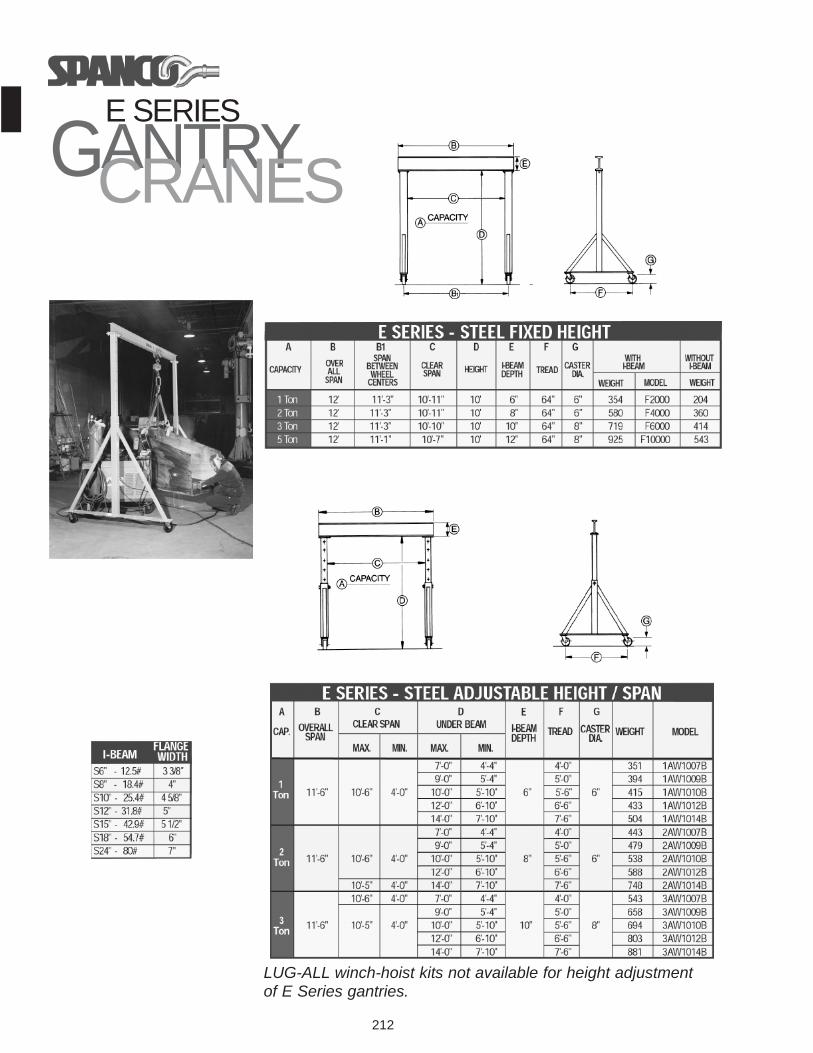
E SERIES
GANTRYCRANES
LUG-ALL winch-hoist kits not available for height adjustmentof E Series gantries.
213
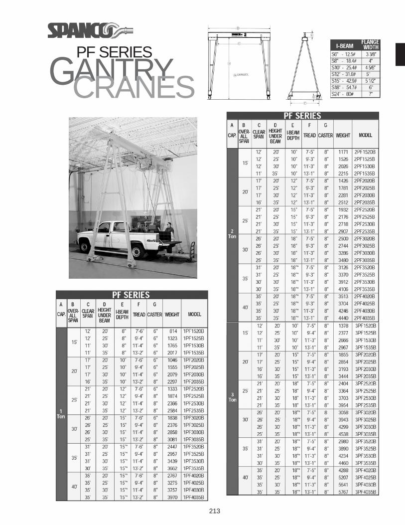
PF SERIES
GANTRYCRANES

214
PF SERIES
GANTRYCRANES

215
POWER DRIVES - Available on T and PF Series onlyPower drive kit includes two-drive assemblies with either
polyurethane (trackless) or V-groove wheels, sprockets,chains, two-gear reducers, two single-speed, 230/460V-threephase TEFC motors, solid state adjustable “soft start,” andtwo-idler assemblies. Standard travel speed is 50 FPM. Otherspeeds and voltages available on request.
Trackless kit- also includes guide rollers on one drive and one idlerassembly. Idler and drive assemblies are supplied withpolyurethane bumpers.
POWER DRIVES FOR
GANTRYCRANES
TRIPODS TRIPODSQuick, easy setup for heavy
lifting in outdoor areaswith no overhead sup-port.
Steel and aluminum con-struction capacities totwo tons.
• Independently,adjustable legs permituse on uneven groundand adjust on six inchcenters.
• Standard lashing kit, included with every tripod, prevents legsfrom spreading on hard or soft surfaces.
Free swiveling eyebolt hangs
plumb to protect tri-pod head from
twist and strain.
Aluminum feet areused on all hard
surfaces. Standardon all models
unless otherwisespecified.
Mud feet are usedon soft ground.
Integral spikes firm-ly entrench legs toprevent slipping or
sinking into ground.Complete inter-
changeability withaluminum feet and
available in place ofaluminum feet or
as an optionalaccessory.