free residual chlorine sensor assembly - automation … rosem… · · 2015-02-05the free...
TRANSCRIPT
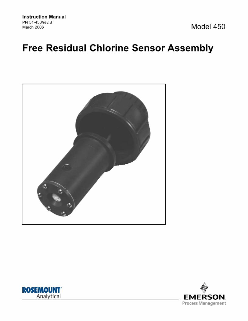
Model 450
Free Residual Chlorine Sensor Assembly
Instruction ManualPN 51-450/rev.B
March 2006
CAUTION
SENSOR/PROCESS
APPLICATION COMPATIBILITY
The wetted sensor materials may not
be compatible with process com-
position and operating conditions.
Application compatibility is entirely the
responsibility of the user.
DANGER
HAZARDOUS AREA INSTALLATION
Installations near flammable liquids or in haz-
ardous area locations must be carefully eval-
uated by qualified on site safety personnel.
This sensor is not Intrinsically Safe or
Explosion Proof.
To secure and maintain an intrinsically safe
installation, the certified safety barrier,
transmitter, and sensor combination must
be used. The installation system must com-
ply with the governing approval agency (FM,
CSA or BASEEFA/CENELEC) hazardous
area classification requirements. Consult
your analyzer/transmitter instruction manual
for details.
Proper installation, operation and servicing
of this sensor in a Hazardous Area Instal-
lation is entirely the responsibility of the user.
ESSENTIAL INSTRUCTIONSREAD THIS PAGE BEFORE PRO-
CEEDING!
Rosemount Analytical designs, manufactures, and tests itsproducts to meet many national and international stan-dards. Because these instruments are sophisticated tech-nical products, you must properly install, use, and maintainthem to ensure they continue to operate within their normalspecifications. The following instructions must be adheredto and integrated into your safety program when installing,using, and maintaining Rosemount Analytical products.Failure to follow the proper instructions may cause any oneof the following situations to occur: Loss of life; personalinjury; property damage; damage to this instrument; andwarranty invalidation.
• Read all instructions prior to installing, operating, and
servicing the product. If this Instruction Manual is not the
correct manual, telephone 1-800-654-7768 and the
requested manual will be provided. Save this Instruction
Manual for future reference.
• If you do not understand any of the instructions, contact
your Rosemount representative for clarification.
• Follow all warnings, cautions, and instructions marked
on and supplied with the product.
• Inform and educate your personnel in the proper instal-
lation, operation, and maintenance of the product.
• Install your equipment as specified in the Installation
Instructions of the appropriate Instruction Manual and
per applicable local and national codes. Connect all
products to the proper electrical and pressure sources.
• To ensure proper performance, use qualified personnel
to install, operate, update, program, and maintain the
product.
• When replacement parts are required, ensure that qual-
ified people use replacement parts specified by
Rosemount. Unauthorized parts and procedures can
affect the product’s performance and place the safe
operation of your process at risk. Look alike substitu-
tions may result in fire, electrical hazards, or improper
operation.
• Ensure that all equipment doors are closed and protec-
tive covers are in place, except when maintenance is
being performed by qualified persons, to prevent electri-
cal shock and personal injury.
Emerson Process Management
Liquid Division2400 Barranca Parkway
Irvine, CA 92606 USA
Tel: (949) 757-8500
Fax: (949) 474-7250
http://www.RAuniloc.com
© Rosemount Analytical Inc. 2006

MODEL 450 TABLE OF CONTENTS
MODEL 450
FREE RESIDUAL CHLORINE SENSOR
TABLE OF CONTENTS
Section Title Page
1.0 DESCRIPTION AND SPECIFICATIONS ................................................................ 1
1.1 Features and Applications ....................................................................................... 1
1.2 Specifications........................................................................................................... 1
1.3 Ordering Information................................................................................................ 2
2.0 INSTALLATION....................................................................................................... 3
2.1 General .................................................................................................................... 3
2.2 Inspection and Unpacking ....................................................................................... 3
2.3 Application Requirements........................................................................................ 3
2.4 Preparation for Installation and Startup ................................................................... 3
2.5 Installation................................................................................................................ 4
3.0 TROUBLESHOOTING ............................................................................................ 6
3.1 General .................................................................................................................... 6
3.2 Troubleshooting the Model 450 Sensor .................................................................. 6
4.0 MAINTENANCE ...................................................................................................... 9
4.1 General .................................................................................................................... 9
4.2 Scheduled Preventative Maintenance..................................................................... 9
4.3 Sensor Disassembly, Rebuild and Assembly Procedure ........................................ 9
5.0 PARTS LISTS ......................................................................................................... 11
6.0 RETURN OF MATERIAL ........................................................................................ 15
i
MODEL 450 TABLE OF CONTENTS
MODEL 450
FREE RESIDUAL CHLORINE SENSOR
LIST OF FIGURES
Figure Title Page
1-1 Model 450 Dimensional Data 2
2-1 Model 450-01 and 450-02 Sensor Installation Diagrams 4
2-2 Handrail Mounting Installation for Model 450-03 and 450-04 Sensor Assemblies 5
5-1 Models 450-01 and 450-02 Free Residual Chlorine Flow Through Sensors 11
5-2 Model 450-03 Free Residual Chlorine Submersion Sensor 12
5-3 Model 450-04 Free Residual Chlorine Submersion Sensor/Agitator 13
5-4 Model 450 Free Residual Chlorine Sensor Assembly 14
LIST OF TABLES
Table Title Page
3-1 Temperature Resistance Chart 7
3-2 Model 1054A TFC Quick Troubleshooting Chart 8

1
MODEL 450 SECTION 1.0
DESCRIPTION AND SPECIFICATIONS
SECTION 1.0DESCRIPTION AND SPECIFICATIONS
1.1 FEATURES AND APPLICATIONS
The Rosemount Analytical Model 450 Free ResidualChlorine Sensor, used with the Model 1054A TotalFree Chlorine Analyzer and the Models 1181 or 853free residual chlorine analyzer/transmitter, measuresthe free residual chlorine level in a wide variety ofapplications, such as: Potable water treatment,sewage plant effluent, cooling tower chlorination con-trol, swimming pools, and industrial waste treatmentplant effluent.
The Model 450 sensor is constructed of PVC withpolymer membrane, hardwood liquid junction*, andstainless steel hardware. The sensor is designed forflow (Codes 01 and 02), submersion in a flowing sam-ple (Code 03), and submersion in a stagnant pond(Code 04). All sensors are furnished with an integral20-foot cable. The Code Option 04 incorporates anagitator and impeller, with a 20-foot power cord, foragitation of a stagnant solution so a fresh sample isalways present at the sensor membrane in submer-sion applications.
The membrane retainer** is designed for ease ofinstallation, and provides adequate tension on themembrane to insure an accurate measurement. Inaddition, the electrolyte chamber incorporates a pres-sure compensator to maintain equal pressure on bothsides of the membrane, despite sample pressurechanges. A thermistor or an RTD for automatic tem-perature compensation is incorporated in the tip of thesensor to adjust for temperature change effects on thediffusion rate of free residual chlorine across themembrane.
The sensor requires very little maintenance andrequires no special tools or fixtures.
1.2 SPECIFICATIONS
Temperature: 0 to 50°C (32 to 122°F)
Pressure: 0 to 345 kPa abs (0 to 50 psig)
Material: Housing: PVCHardware: Stainless steelLiquid Junction: HardwoodO-Rings: Buna-NMembrane: PolymerCathode: GoldAnode: Silver
Minimum Sample Flow Rate:Code 01 & 02: 0.13 liter/sec (2 GPM)Code 03: 0.3 meter/sec (1 ft/sec)Code 04: None
Agitator Power Requirement:(Model Code 04 only): 115 VAC ±10% 60Hz (0.2amp)
Weight/Shipping Weight:Code 01, 02 & 03: 0.9 kg/1.8 kg (2lbs/4 lbs)Code 04: 2.3 kg/3.2 kg (5 lbs/7lbs)
• ELIMINATES THE NEED FOR WET CHEMICAL ANALYSIS.
• LOW MAINTENANCE with up to 12 months between rechargings.
• THREE CONFIGURATIONS AVAILABLE to meet most applications.
• COMPACT DESIGN provides for ease of installation and service.
*U.S. Patent No. 4,187,162
**U.S. Patent No. 3,887,194Canadian Patent No. 1,025,496

2
MODEL 450 SECTION 1.0
DESCRIPTION AND SPECIFICATIONS
1.3 ORDERING INFORMATIONModel 450 Free Residual Chlorine Sensor Includes PVC sensor housing with integral chlorine permeablemembrane and temperature compensator.
MODEL450 FREE RESIDUAL CHLORINE SENSOR (3 lbs./1.5 kg)
CODE MOUNTING HARDWARE
01 1-1/2 inch PVC cell, 90° flow
02 1-1/2 inch PVC cell, 180° flow
03 PVC union with 3/4 inch FNPT for submersion service
04 PVC union with 1 inch FNPT, and agitator with 20-ft. cable for submersions. Agitator motor requires 115 VAC power only.
450 01 17 EXAMPLE
CODE OPTIONS
11 Stainless steel tags (specify marking)
14 Handrail mounting bracket (P/N 1000857) for use with J-box (see Code 17 below)
15 Handrail mounting bracket (P/N 1000856) for use with Model 803
17 Weatherproof NEMA 4X junction box (P/N 22719-02)
54 For use with Models 1054A TFC
NOTE: Recommended cable from sensor to transmitter is Belden 8434 or equivalent, available from Rosemount Analytical (P/N 9200074).
Specify length.
FIGURE 1-1. MODEL 450 DIMENSIONAL DATA
*CODE 02 SAME AS CODE 01 EXCEPT SENSOR MOUNTED IN TOP OF TEE, WITH FLOW IN EITHER DIRECTION
3
MODEL 450 SECTION 2.0
INSTALLATION
SECTION 2.0
INSTALLATION
2.1 GENERAL. This section provides installationinstructions for the Model 450 Sensor Assembly.
2.2 INSPECTION AND UNPACKING. Inspect the ship-ping container for any evidence of damage. If damageis evident, notify the carrier immediately. If no damageis evident, open the container and inspect the sensor.Save the container for shipment to the factory for serv-ice.
2.3 APPLICATION REQUIREMENTS. The Model 450is designed for typical clean water application. It isNOT designed for the following:
1. Processes containing ammonia (municipal waste water).
2. Processes containing sea water or bromine chem-ical additions.
3. Low conductivity processes, less than 50 micro-siemens (reverse osmosis).
4. Post-dechlorination processes (example: afteradding sodium bisulfite).
2.4 SENSOR PREPARATION FOR INSTALLATIONAND START-UP. The plumbing fittings provided on theModel 450 Sensor differ slightly, depending on the pipingrequirements. However, the main body, or chlorine sens-ing portion of each of the different codes, is identical. Eachsensor is shipped from the factory dry and without amembrane installed. The recharge kit which accompa-nies the sensor contains one bottle of dry electrolyte andfive membranes. The sensor should be charged utilizingthe following procedure:
CAUTIONClean rubber gloves should be worn duringsensor preparation and maintenance toavoid skin contact and contaminating themembrane and cathode.
1. Prepare sensor electrolyte by filling the bottle ofcrystals supplied with the recharge kit (Ag Cl/KCI)to the neck with distilled or deionized water. Stir orshake to wet crystals thoroughly. Some crystalsshould remain undissolved.
NOTEPlease see Figure 5-4 for Model 450 FreeResidual Sensor assembly exploded view.
2. Remove sensor “cover” and membrane “Retainer”(remove 6 screws at sensor tip).
3. Sand the gold cathode with the 400 grit sandpa-per, in one direction only until it is shiny. Rinsecathode with clean water.
4. Remove the fill-plug.
5. Fill the syringe (included in the recharge kit) withthe AgCl/KCl electrolyte solution. Fill the sensorbody with the electrolyte, shaking the sensor toremove air. Ensure that about 1 cc (or 1 ml) ofcrystals get inside the sensor body.
6. Install the fill plug (wrapped with one or two turnsof TEFLON®1 tape in the side of the sensor. As theplug is screwed into place, electrolyte will beforced through the wood junction. This is impor-tant, since the electrical continuity will not beestablished unless the wood junction is thorough-ly wetted.
Continue to screw the fill plug into place until it is flushwith the sensor body. Do not remove excess electrolytefrom the end of the sensor because it will wet the mem-brane and help hold it in place during installation.
7. Place the O-ring in the groove and press it into posi-tion around the wood junction. If there is no solutionremaining over the gold cathode after installing the O-ring, add a few drops of electrolyte (no crystals).IMPORTANT: No crystals underneath the mem-brane or damage will occur.
8. Place the white-opaque “membrane” on top of thecathode. Place the white-translucent “protector”over the membrane. DO NOT use the blue-paperprotective separators found in the membrane kit!
9. Lay the membrane “retainer” over the membraneand protector. Screw down the (6) screws applyingeven pressure. The membrane should be taut, notspongy, when the retainer is secure.
10. Keep the sensor tip in water if installation is delayedover an hour. Membrane may adhere to the cath-ode if allowed to dry out.
11. Sensor requires approximately (2) hours to polar-ize and (12-24) hours to obtain a stable zero inchlorine-free water.
NOTEWater should be agitated for zeroing andspanning (magnetic stirrer is recommended)
CAUTIONInsufficient zeroing time may cause diffi-culties in calibration and readings thatdrift.
1 Reg. U.S. Pat. Office for DuPont's fluorocarbon resins
4
MODEL 450 SECTION 2.0
INSTALLATION
12. Chlorine concentrations of 1 PPM or above are rec-ommended for the most accurate chlorine calibration.IMPORTANT: Process flow requirement is 1 ft./sec.or if in a “Tee” 2.0-5.0 gal./min. If unable to adjustprocess chlorine concentration to this level, performcalibration in a beaker with a magnetic stirrer for agi-tation. Adding a drop or two of chlorine bleach todeionized water (buffered to 7 pH) will create a chlo-rine residual.
13. Calibrate the chlorine reading to the titrated valueof the process or the chlorine residual sample.
14. The sensor is now ready to be installed.
2.5 INSTALLATION.
2.5.1 Mechanical Installation.
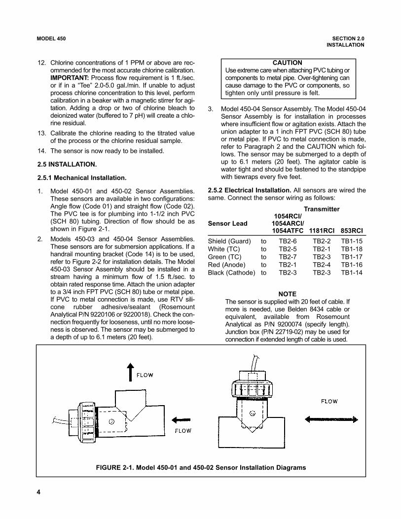
1. Model 450-01 and 450-02 Sensor Assemblies.These sensors are available in two configurations:Angle flow (Code 01) and straight flow (Code 02).The PVC tee is for plumbing into 1-1/2 inch PVC(SCH 80) tubing. Direction of flow should be asshown in Figure 2-1.
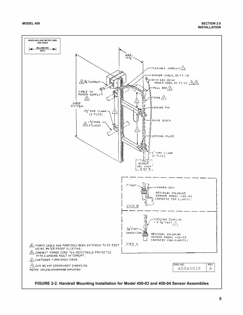
2. Models 450-03 and 450-04 Sensor Assemblies.These sensors are for submersion applications. If ahandrail mounting bracket (Code 14) is to be used,refer to Figure 2-2 for installation details. The Model450-03 Sensor Assembly should be installed in astream having a minimum flow of 1.5 ft./sec. toobtain rated response time. Attach the union adapterto a 3/4 inch FPT PVC (SCH 80) tube or metal pipe.If PVC to metal connection is made, use RTV sili-cone rubber adhesive/sealant (RosemountAnalytical P/N 9220106 or 9220018). Check the con-nection frequently for looseness, until no more loose-ness is observed. The sensor may be submerged toa depth of up to 6.1 meters (20 feet).
CAUTIONUse extreme care when attaching PVC tubing orcomponents to metal pipe. Over-tightening cancause damage to the PVC or components, sotighten only until pressure is felt.
3. Model 450-04 Sensor Assembly. The Model 450-04Sensor Assembly is for installation in processeswhere insufficient flow or agitation exists. Attach theunion adapter to a 1 inch FPT PVC (SCH 80) tubeor metal pipe. If PVC to metal connection is made,refer to Paragraph 2 and the CAUTION which fol-lows. The sensor may be submerged to a depth ofup to 6.1 meters (20 feet). The agitator cable iswater tight and should be fastened to the standpipewith tiewraps every five feet.
2.5.2 Electrical Installation. All sensors are wired thesame. Connect the sensor wiring as follows:
NOTEThe sensor is supplied with 20 feet of cable. Ifmore is needed, use Belden 8434 cable orequivalent, available from RosemountAnalytical as P/N 9200074 (specify length).Junction box (P/N 22719-02) may be used forconnection if extended length of cable is used.
FIGURE 2-1. Model 450-01 and 450-02 Sensor Installation Diagrams
Transmitter1054RCI/
Sensor Lead 1054ARCI/1054ATFC 1181RCI 853RCI
Shield (Guard) to TB2-6 TB2-2 TB1-15
White (TC) to TB2-5 TB2-1 TB1-18
Green (TC) to TB2-7 TB2-3 TB1-17
Red (Anode) to TB2-1 TB2-4 TB1-16
Black (Cathode) to TB2-3 TB2-3 TB1-14
5
MODEL 450 SECTION 2.0
INSTALLATION
FIGURE 2-2. Handrail Mounting Installation for Model 450-03 and 450-04 Sensor Assemblies
WHEN INCH AND METRIC DIMS
ARE GIVEN
MILLIMETER
INCH
DWG. NO. REV.
40045019 A
6
3.1 GENERAL. This section contains troubleshooting
data for the Model 450 Sensor Assembly.
3.2 TROUBLESHOOTING THE MODEL 450
SENSOR. The majority of problems encountered in
RCI systems are caused by improper maintenance, or
from internal leakage within the sensor.
Disassemble the sensor completely by removing the
membrane retainer and sensor body (see Section 4.3
and Figure 5-4). The membrane may have dried on to
the gold cathode. Soak this loose with water as scraping
will damage the gold tip. A wet wood junction will make
the sensor body very difficult to remove but a firm twist-
ing, pulling motion should loosen it.
Clean all parts with clean water and dry them. Check for
visible damage (i.e., cracks, deep cuts, broken silver
wires). Perform the following checks with an ohmmeter.
Check T.C. resistance between the green and white
wires. Check continuity between the red wire and the sil-
ver anode, and between the black wire and the gold
cathode (be careful not to scratch the gold). Perform a
high meg check between the following (100 megohms
minimum): Shield; Black; Red; Green or White. If every-
thing checks O.K., the sensor should function after a
proper recharge. If the silver anode appears oxidized, it
may be cleaned with wet or dry 400 sandpaper. Also
brush the gold tip two or three times with 400 sandpaper
in one direction only.
Assemble the body of the RCI sensor and calibrate per
Section 2.4. NOTE
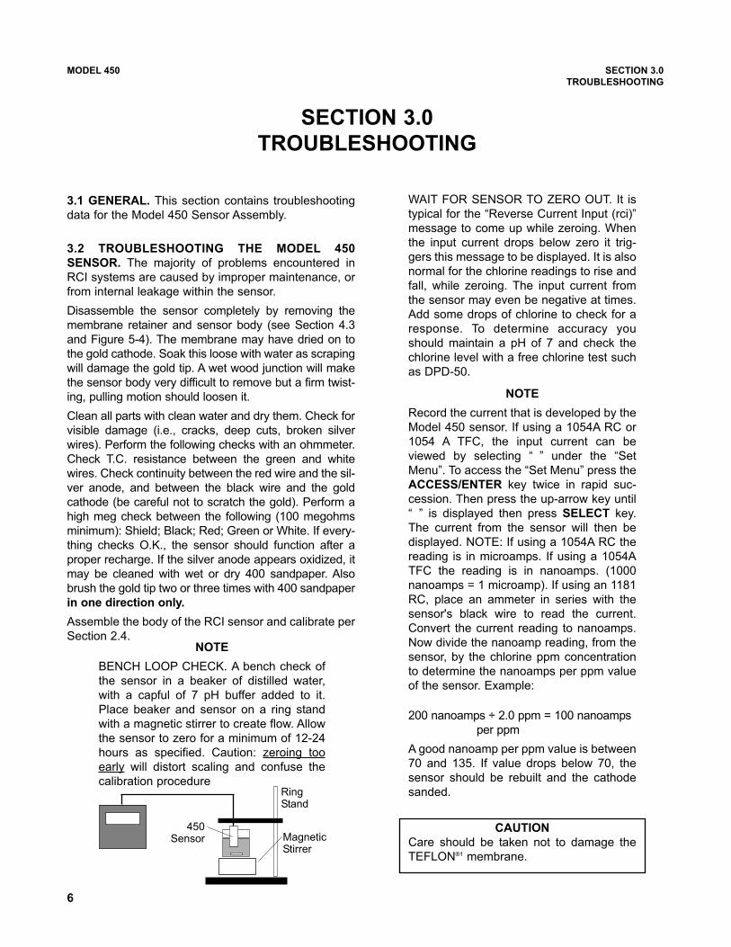
BENCH LOOP CHECK. A bench check of
the sensor in a beaker of distilled water,
with a capful of 7 pH buffer added to it.
Place beaker and sensor on a ring stand
with a magnetic stirrer to create flow. Allow
the sensor to zero for a minimum of 12-24
hours as specified. Caution: zeroing too
early will distort scaling and confuse the
calibration procedure
MODEL 450 SECTION 3.0
TROUBLESHOOTING
SECTION 3.0
TROUBLESHOOTING
WAIT FOR SENSOR TO ZERO OUT. It is
typical for the “Reverse Current Input (rci)”
message to come up while zeroing. When
the input current drops below zero it trig-
gers this message to be displayed. It is also
normal for the chlorine readings to rise and
fall, while zeroing. The input current from
the sensor may even be negative at times.
Add some drops of chlorine to check for a
response. To determine accuracy you
should maintain a pH of 7 and check the
chlorine level with a free chlorine test such
as DPD-50.
NOTE
Record the current that is developed by the
Model 450 sensor. If using a 1054A RC or
1054 A TFC, the input current can be
viewed by selecting “jo” under the “Set
Menu”. To access the “Set Menu” press the
ACCESS/ENTER key twice in rapid suc-
cession. Then press the up-arrow key until
“jo” is displayed then press SELECT key.
The current from the sensor will then be
displayed. NOTE: If using a 1054A RC the
reading is in microamps. If using a 1054A
TFC the reading is in nanoamps. (1000
nanoamps = 1 microamp). If using an 1181
RC, place an ammeter in series with the
sensor's black wire to read the current.
Convert the current reading to nanoamps.
Now divide the nanoamp reading, from the
sensor, by the chlorine ppm concentration
to determine the nanoamps per ppm value
of the sensor. Example:
200 nanoamps ÷ 2.0 ppm = 100 nanoamps
per ppm
A good nanoamp per ppm value is between
70 and 135. If value drops below 70, the
sensor should be rebuilt and the cathode
sanded.
CAUTION
Care should be taken not to damage the
TEFLON®1 membrane.
450Sensor Magnetic
Stirrer
RingStand
7
MODEL 450 SECTION 3.0
TROUBLESHOOTING
If the resistance as specified above cannot be
achieved, replace the sensor.
4. To check for shorted sensor leads, measure the
resistance between one temperature compensator
wire (green or white) and the cathode (black) lead
and anode (red) lead. The meter should indicate
an open circuit (100 megohms or more). Repeat
the measurement using the other temperature
compensator wire. If the sensor shows a short cir-
cuit, the sensor is defective and should be
replaced.
1 Reg. U.S. Pat. Office for DuPont's fluorocarbon resins
1. Low readings and inability to calibrate are gener-
ally the result of a coated membrane. Replace the
coated membrane and return the sensor to serv-
ice.
2. Readings offscale and inability to calibrate are
usually caused by a damaged membrane. If this is
the case, replace the membrane.
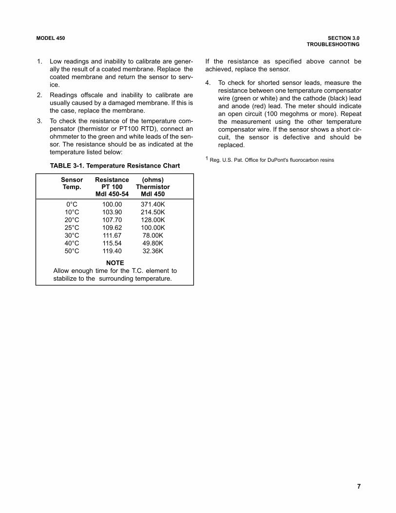
3. To check the resistance of the temperature com-
pensator (thermistor or PT100 RTD), connect an
ohmmeter to the green and white leads of the sen-
sor. The resistance should be as indicated at the
temperature listed below:
TABLE 3-1. Temperature Resistance Chart
Sensor Resistance (ohms)Temp. PT 100 Thermistor
Mdl 450-54 Mdl 450
0°C 100.00 371.40K
10°C 103.90 214.50K
20°C 107.70 128.00K
25°C 109.62 100.00K
30°C 111.67 78.00K
40°C 115.54 49.80K
50°C 119.40 32.36K
NOTE
Allow enough time for the T.C. element to
stabilize to the surrounding temperature.
MODEL 450 SECTION 3.0
TROUBLESHOOTING
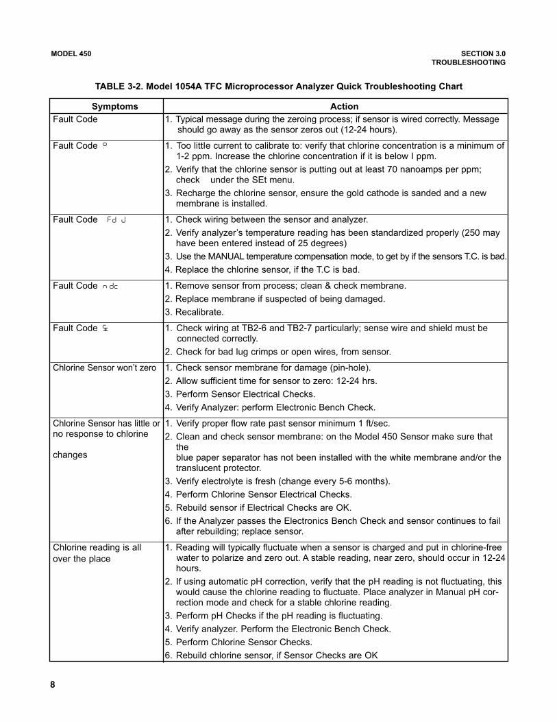
TABLE 3-2. Model 1054A TFC Microprocessor Analyzer Quick Troubleshooting Chart
Symptoms Action
Fault Code �sdj� 1. Typical message during the zeroing process; if sensor is wired correctly. Messageshould go away as the sensor zeros out (12-24 hours).
Fault Code �cbe� 1. Too littIe current to calibrate to: verify that chlorine concentration is a minimum of1-2 ppm. Increase the chlorine concentration if it is below I ppm.
2. Verify that the chlorine sensor is putting out at least 70 nanoamps per ppm;check �jo� under the SEt menu.
3. Recharge the chlorine sensor, ensure the gold cathode is sanded and a newmembrane is installed.
Fault Code �udI�0�udM� 1. Check wiring between the sensor and analyzer.
2. Verify analyzer’s temperature reading has been standardized properly (250 mayhave been entered instead of 25 degrees)
3. Use the MANUAL temperature compensation mode, to get by if the sensors T.C. is bad.
4. Replace the chlorine sensor, if the T.C is bad.
Fault Code �Pso0�Fdj� 1. Remove sensor from process; clean & check membrane.
2. Replace membrane if suspected of being damaged.
3. Recalibrate.
Fault Code �TFo� 1. Check wiring at TB2-6 and TB2-7 particularly; sense wire and shield must be connected correctly.
2. Check for bad lug crimps or open wires, from sensor.
Chlorine Sensor won’t zero 1. Check sensor membrane for damage (pin-hole).
2. Allow sufficient time for sensor to zero: 12-24 hrs.
3. Perform Sensor Electrical Checks.
4. Verify Analyzer: perform Electronic Bench Check.
Chlorine Sensor has little or 1. Verify proper flow rate past sensor minimum 1 ft/sec.no response to chlorine 2. Clean and check sensor membrane: on the Model 450 Sensor make sure that
thechanges blue paper separator has not been installed with the white membrane and/or the
translucent protector.
3. Verify electrolyte is fresh (change every 5-6 months).
4. Perform Chlorine Sensor Electrical Checks.
5. Rebuild sensor if Electrical Checks are OK.
6. If the Analyzer passes the Electronics Bench Check and sensor continues to failafter rebuilding; replace sensor.
Chlorine reading is all 1. Reading will typically fluctuate when a sensor is charged and put in chlorine-free
over the place water to polarize and zero out. A stable reading, near zero, should occur in 12-24hours.
2. If using automatic pH correction, verify that the pH reading is not fluctuating, thiswould cause the chlorine reading to fluctuate. Place analyzer in Manual pH cor-rection mode and check for a stable chlorine reading.
3. Perform pH Checks if the pH reading is fluctuating.
4. Verify analyzer. Perform the Electronic Bench Check.
5. Perform Chlorine Sensor Checks.
6. Rebuild chlorine sensor, if Sensor Checks are OK
8
9
MODEL 450 SECTION 4.0
MAINTENANCE
SECTION 4.0
MAINTENANCE
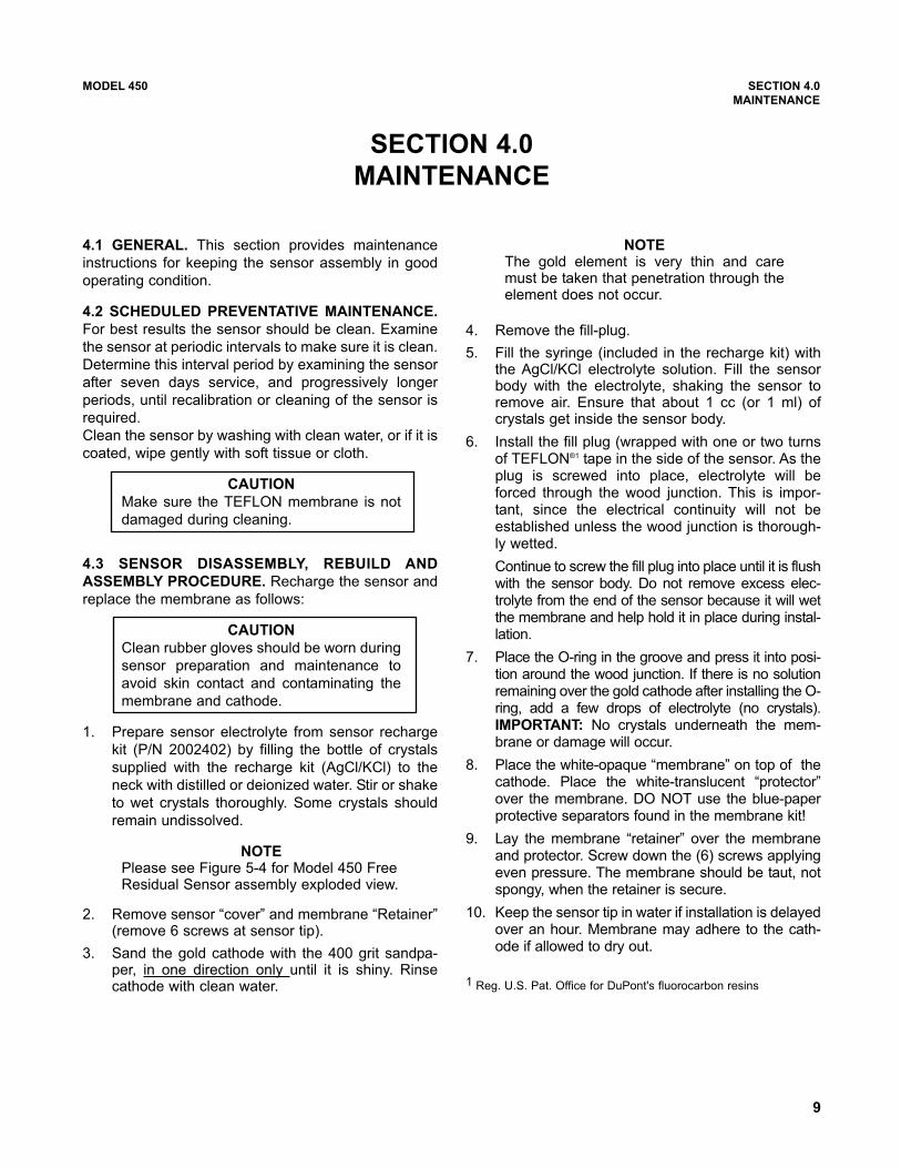
4.1 GENERAL. This section provides maintenance
instructions for keeping the sensor assembly in good
operating condition.
4.2 SCHEDULED PREVENTATIVE MAINTENANCE.
For best results the sensor should be clean. Examine
the sensor at periodic intervals to make sure it is clean.
Determine this interval period by examining the sensor
after seven days service, and progressively longer
periods, until recalibration or cleaning of the sensor is
required.
Clean the sensor by washing with clean water, or if it is
coated, wipe gently with soft tissue or cloth.
CAUTION
Make sure the TEFLON membrane is not
damaged during cleaning.
4.3 SENSOR DISASSEMBLY, REBUILD AND
ASSEMBLY PROCEDURE. Recharge the sensor and
replace the membrane as follows:
CAUTION
Clean rubber gloves should be worn during
sensor preparation and maintenance to
avoid skin contact and contaminating the
membrane and cathode.
1. Prepare sensor electrolyte from sensor recharge
kit (P/N 2002402) by filling the bottle of crystals
supplied with the recharge kit (AgCl/KCl) to the
neck with distilled or deionized water. Stir or shake
to wet crystals thoroughly. Some crystals should
remain undissolved.
NOTEPlease see Figure 5-4 for Model 450 FreeResidual Sensor assembly exploded view.
2. Remove sensor “cover” and membrane “Retainer”(remove 6 screws at sensor tip).
3. Sand the gold cathode with the 400 grit sandpa-per, in one direction only until it is shiny. Rinsecathode with clean water.
NOTEThe gold element is very thin and caremust be taken that penetration through theelement does not occur.
4. Remove the fill-plug.
5. Fill the syringe (included in the recharge kit) withthe AgCl/KCl electrolyte solution. Fill the sensorbody with the electrolyte, shaking the sensor toremove air. Ensure that about 1 cc (or 1 ml) ofcrystals get inside the sensor body.
6. Install the fill plug (wrapped with one or two turnsof TEFLON®1 tape in the side of the sensor. As theplug is screwed into place, electrolyte will beforced through the wood junction. This is impor-tant, since the electrical continuity will not beestablished unless the wood junction is thorough-ly wetted.
Continue to screw the fill plug into place until it is flushwith the sensor body. Do not remove excess elec-trolyte from the end of the sensor because it will wetthe membrane and help hold it in place during instal-lation.
7. Place the O-ring in the groove and press it into posi-tion around the wood junction. If there is no solutionremaining over the gold cathode after installing the O-ring, add a few drops of electrolyte (no crystals).IMPORTANT: No crystals underneath the mem-brane or damage will occur.
8. Place the white-opaque “membrane” on top of thecathode. Place the white-translucent “protector”over the membrane. DO NOT use the blue-paperprotective separators found in the membrane kit!
9. Lay the membrane “retainer” over the membraneand protector. Screw down the (6) screws applyingeven pressure. The membrane should be taut, notspongy, when the retainer is secure.
10. Keep the sensor tip in water if installation is delayedover an hour. Membrane may adhere to the cath-ode if allowed to dry out.
1 Reg. U.S. Pat. Office for DuPont's fluorocarbon resins
10
MODEL 450 SECTION 4.0
MAINTENANCE
11. Sensor requires approximately (2) hours to polar-ize and (12-24) hours to obtain a stable zero inchlorine-free water.
NOTEWater should be agitated for zeroing andspanning (magnetic stirrer is recommended)
CAUTIONInsufficient zeroing time may cause diffi-culties in calibration and readings thatdrift.
12. Chlorine concentrations of 1 PPM or above are rec-ommended for the most accurate chlorine calibration.
IMPORTANTProcess flow requirement is 1 ft./sec. or if in a“Tee” 0.5-5.0 gal./min. If unable to adjust processchlorine concentration to this level, perform cali-bration in a beaker with a magnetic stirrer for agi-tation. Adding a drop or two of chlorine bleach todeionized water (buffered to 7 pH) will createa chlorine residual.
13. Calibrate the chlorine reading to the titrated value ofthe process or the chlorine residual sample.
14. The sensor is now ready to be installed.
15. Refer to the Model 1054A TFC, 1181 RC or 853instruction manual for standardization procedure.
11
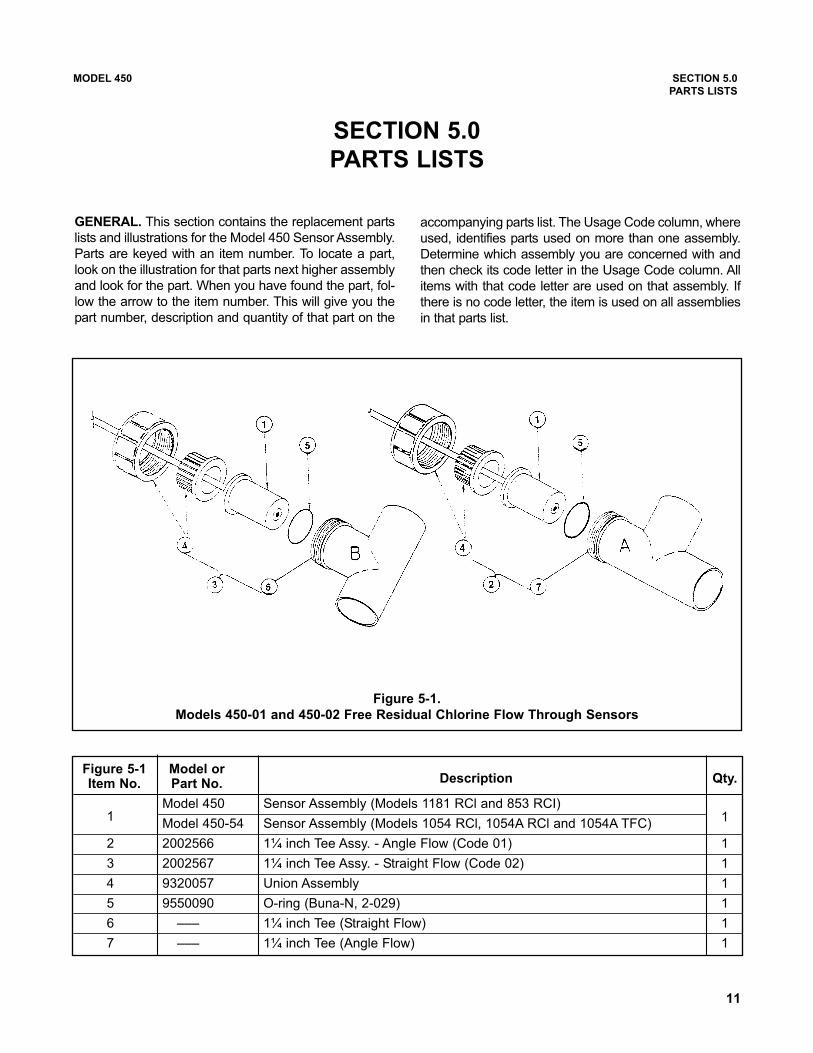
Figure 5-1 Model orItem No. Part No. Description Qty.
Model 450 Sensor Assembly (Models 1181 RCl and 853 RCI)11
Model 450-54 Sensor Assembly (Models 1054 RCl, 1054A RCl and 1054A TFC)
2 2002566 1¼ inch Tee Assy. - Angle Flow (Code 01) 1
3 2002567 1¼ inch Tee Assy. - Straight Flow (Code 02) 1
4 9320057 Union Assembly 1
5 9550090 O-ring (Buna-N, 2-029) 1
6 ––– 1¼ inch Tee (Straight Flow) 1
7 ––– 1¼ inch Tee (Angle Flow) 1
MODEL 450 SECTION 5.0
PARTS LISTS
SECTION 5.0
PARTS LISTS
GENERAL. This section contains the replacement parts
lists and illustrations for the Model 450 Sensor Assembly.
Parts are keyed with an item number. To locate a part,
look on the illustration for that parts next higher assembly
and look for the part. When you have found the part, fol-
low the arrow to the item number. This will give you the
part number, description and quantity of that part on the
accompanying parts list. The Usage Code column, where
used, identifies parts used on more than one assembly.
Determine which assembly you are concerned with and
then check its code letter in the Usage Code column. All
items with that code letter are used on that assembly. If
there is no code letter, the item is used on all assemblies
in that parts list.
Figure 5-1.
Models 450-01 and 450-02 Free Residual Chlorine Flow Through Sensors
12
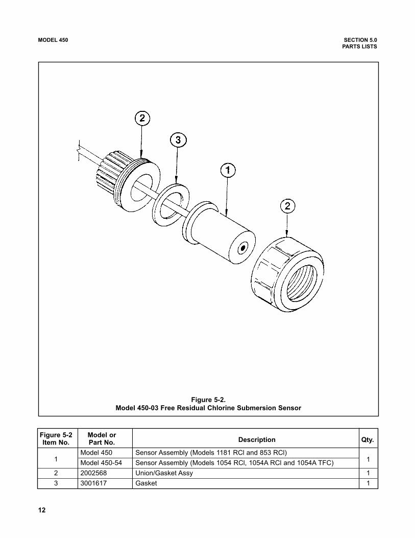
Figure 5-2 Model orItem No. Part No. Description Qty.
Model 450 Sensor Assembly (Models 1181 RCl and 853 RCl)11
Model 450-54 Sensor Assembly (Models 1054 RCl, 1054A RCl and 1054A TFC)
2 2002568 Union/Gasket Assy 1
3 3001617 Gasket 1
Figure 5-2.
Model 450-03 Free Residual Chlorine Submersion Sensor
MODEL 450 SECTION 5.0
PARTS LISTS

13
Figure 5-3 Model orItem No. Part No. Description Qty.
Model 450 Sensor Assembly (Models 1181 RCI and 853 RCl)11
Model 450-54 Sensor Assembly (Models 1054 RCl, 1054A RCl and 1054A TFC)
2 2002569 Pump, submersible Assy. 1
3 Screw, SPH SS (#8-32 X 3/8) 4
4 Screw, SPH SS (#8-32 X 3/8) 2
5 Holder Assy 1
6 ––– Union 1
7 3001197 Gasket 1
Figure 5-3.
Model 450-04 Free Residual Chlorine Submersion Sensor/Agitator
MODEL 450 SECTION 5.0
PARTS LISTS

14
Figure 5-4 Model orItem No. Part No. Description Qty.
1 ––– Screw (#4-40 X 1.0) 4
2 ––– Base Assy. Sensor (Model 450/450-54) 1
3 9550144 O-ring (Viton®1,2-222) 1
4 9550056 O-ring (Viton®1, 2-210) 1
5 3002010 Junction, wood 1
6 ––– Body, sensor 1
7 33209-00 Plug, fill 1
8 9550110 O-ring (Viton®1, 2-016) 1
9 2001996 Membrane kit contains five membrane, five polyester filter and
two O-rings (Item 8). Discard blue paper between mesh and membrane. 1
10 ––– Retainer, membrane 1
11 ––– Screw (#4-40 X 0.37) 6
12 ––– Cap, protective 1
2002402 Kit, recharge, chlorine sensor contains the following items: 1
3002010 Junction, wood (same as Item 5) 1
2001996 Membrane kit (same as Item 9) 1
9210001 Solution (AgCI/CKI) 1
––– Syringe (for filling sensor) 1
Figure 5-4. Model 450 Free Residual Chlorine Sensor Assembly
MODEL 450 SECTION 5.0
PARTS LISTS
1 Viton is a registered trademark of DuPont Performance Elastomers.
NOTE
blue protective separator between mem-
brane and mesh is to be discarded

15
Model 450 SECTION 6.0
RETURN OF MATERIAL
SECTION 6.0RETURN OF MATERIAL
6.1 GENERAL. To expedite the repair and return of
instruments, proper communication between the cus-
tomer and the factory is important. A return material
authorization number is required. Call 1-800-654-
7768 or (949) 757-8500. The “Return of Materials
Request” form is provided for you to copy and use in
case the situation arises. The accuracy and complete-
ness of this form will affect the processing time of your
materials.
6.2 WARRANTY REPAIR. The following is the proce-
dure for returning products still under warranty.
1. Contact the factory for authorization.
2. Complete a copy of the “Return of Materials
Request” form as completely and accurately as
possible.
3. To verify warranty, supply the factory sales order
number or the original purchase order number. In
the case of individual parts or sub-assemblies, the
serial number on the mother unit must be sup-
plied.
4. Carefully package the materials and enclose your
“Letter of Transmittal” and the completed copy of
the “Return of Materials Request” form. If possi-
ble, pack the materials in the same manner as it
was received.
IMPORTANT
Please see second section of “Return of
Materials Request Form”. Compliance to
the OSHA requirements is mandatory for
the safety of all personnel. MSDS forms
and a certification that the instruments
have been disinfected or detoxified are
required.
5. Send the package prepaid to:
Rosemount Analytical Inc.
2400 Barranca Parkway
Irvine, CA 92606
Attn: Factory Repair
Mark the package:
Returned for Repair RMA No. _______________
Model No. ______________
6.3 NON WARRANTY REPAIR.
1. Contact the factory for authorization.
2. Fill out a copy of the “Return of Materials Request”
form as completely and accurately as possible.
3. Include a purchase order number and make sure
to include the name and telephone number of the
right individual to be contacted should additional
information be needed.
4. Do Steps 4 and 5 of Section 6.2.
NOTE
Consult the factory for additional infor-
mation regarding service or repair.

MODEL CFA 3000 RETURN OF MATERIAL
RETURN OF MATERIAL
GENERAL.
To expedite the repair and return of instruments, proper communication between the customer and the factory is
important. Before returning a product for repair, call 1-949-757-8500 for a Return Materials Authorization (RMA)
number.
WARRANTY REPAIR.
The following is the procedure for returning instruments still under warranty:
1. Call Emerson Process Management for authorization.
2. To verify warranty, supply the factory sales order number or the original purchase order number. In the case
of individual parts or sub-assemblies, the serial number on the unit must be supplied.
3. Carefully package the materials and enclose your “Letter of Transmittal” (see Warranty). If possible, pack the
materials in the same manner as they were received.
4. Send the package prepaid to:
Emerson Process Management
Liquid Division
2400 Barranca Parkway
Irvine, CA 92606
Attn: Factory Repair
RMA No. ____________
Mark the package: Returned for Repair
Model No. ____
NON-WARRANTY REPAIR.
The following is the procedure for returning for repair instruments that are no longer under warranty:
1. Call Emerson Process Management for authorization.
2. Supply the purchase order number, and make sure to provide the name and telephone number of the individ-
ual to be contacted should additional information be needed.
3. Do Steps 3 and 4 of the Warranty Repair section above.
NOTE
Consult the factory for additional information regarding service or repair.

A Worldwide Network of Sales and Service
Emerson Process Management’s field sales offices are your source for more information on the fill line of Rosemount Analyticalproducts. Field sales personnel will work closely with you to supply technical data and application information.
For more information, please contact your nearest Emerson Process Management sales office.
Immediate, Reliable Analytical Support Now there’s a way to quickly get the right answers for your liquid analytical instrumentation ques-tions: the Analytical Customer Support Center.
Our staff of trained professionals is ready to provide the information you need. If you are placing anorder, verifying delivery, requesting application information, or just want to contact a RosemountAnalytical representative, a call to the Customer Support Center will provide you with the right peo-ple, the right answers, right now.
The right people, the right answers, right now.
THE AMERICAS -HEADQUARTERS
Emerson Process Management
Rosemount Analytical Inc.
Liquid Center of Excellence
2400 Barranca Parkway
Irvine, CA 92606
Phone: +1.949.757.8500
Toll Free: +1.800.854.8257
Fax: +1.949.474.7250
ASIA-PACIFIC
Emerson Process Management
Asia Pacific Private Ltd.
1 Pandan Crescent
Singapore 0512
Republic of Singapore
Phone: 65.777.8211
Fax: 65.777.0947
EUROPE
Emerson Process Management AG
Blegistrasse 21
CH-6341 Baar-Walterswil
Switzerland
T 41.41.768.6111
T 41.41.761.8740
VISIT OUR WEBSITE ATwww.rosemountanalytical.com
GERMANY
Emerson Process Management Process
Gas Analyzer Center of Excellence
GmbH & Co. OHG
Industriestrasse 1
63594 Hasselroth
Germany
T 49.6055.884.0
F 49.6055.884.20
LATIN AMERICA
Emerson Process Management
Rosemount Analytical
10241 West Little York, Suite #200
Houston, TX 77040 USA
T 713.467.6000
F 713.827.3328
MIDDLE EAST AND AFRICA
Emerson Process Management
EPM Building
P. O. Box 17033
Jebe Ali Free Zone
Dubai, United Arab Emirates
T 971.4.8835235
F 971.4.8835312

FROM: RETURN BILL TO:
_____________________________ _____________________________ _____________________________
_____________________________ _____________________________ _____________________________
_____________________________ _____________________________ _____________________________
CUSTOMER/USER MUST SUBMIT MATERIAL SAFETY SHEET (MSDS) OR COMPLETE STREAM COMPOSITION, AND/OR
LETTER CERTIFYING THE MATERIALS HAVE BEEN DISINFECTED AND/OR DETOXIFIED WHEN RETURNING ANY PROD-
UCT, SAMPLE OR MATERIAL THAT HAVE BEEN EXPOSED TO OR USED IN AN ENVIRONMENT OR PROCESS THAT CON-
TAINS A HAZARDOUS MATERIAL ANY OF THE ABOVE THAT IS SUBMITTED TO ROSEMOUNT ANALYTICAL WITHOUT
THE MSDS WILL BE RETURNED TO SENDER C.O.D. FOR THE SAFETY AND HEALTH OF OUR EMPLOYEES. WE THANK
YOU IN ADVANCE FOR COMPLIANCE TO THIS SUBJECT.
SENSOR OR CIRCUIT BOARD ONLY:
(Please reference where from in MODEL / SER. NO. Column)
1. PART NO.__________________________1. MODEL_________________________________1. SER. NO.________________
2. PART NO.__________________________2. MODEL_________________________________2. SER. NO.________________
3. PART NO.__________________________3. MODEL_________________________________3. SER. NO.________________
4. PART NO.__________________________4. MODEL_________________________________4. SER. NO.________________
PLEASE CHECK ONE:
�� REPAIR AND CALIBRATE �� DEMO EQUIPMENT NO. __________________________
�� EVALUATION �� OTHER (EXPLAIN) _______________________________
�� REPLACEMENT REQUIRED? �� YES �� NO _________________________________________________
DESCRIPTION OF MALFUNCTION:
______________________________________________________________________________________________________
______________________________________________________________________________________________________
______________________________________________________________________________________________________
WARRANTY REPAIR REQUESTED:
�� YES-REFERENCE ORIGINAL ROSEMOUNT ANALYTICAL ORDER NO. ________________________________________
CUSTOMER PURCHASE ORDER NO. _________________________________________________
�� NO-PROCEED WITH REPAIRS-INVOICE AGAINST P.O. NO. _________________________________________________
�� NO-CONTACT WITH ESTIMATE OF REPAIR CHARGES: LETTER �� __________________________________________
PHONE �� ___________________________________________
NAME ____________________________________________________ PHONE _________________________________________
ADDRESS ___________________________________________________________________________________________________
______________________________________________________________ ZIP _________________________________________
RETURN AUTHORITY FOR CREDIT ADJUSTMENT [Please check appropriate box(s)]
�� WRONG PART RECEIVED �� REPLACEMENT RECEIVED
�� DUPLICATE SHIPMENT REFERENCE ROSEMOUNT ANALYTICAL SALES ORDER NO.__________
�� RETURN FOR CREDIT RETURN AUTHORIZED BY: ______________________________________
WARRANTY DEFECT____________________________________________________________________________________
_____________________________________________________________________________________________________
24-6047
RETURN OF MATERIALS REQUEST •IMPORTANT!This form must be completed to ensure expedient factory service.
REPAIR
STATUS
REASON
FOR
RETURN
CUSTOMER
NOTICE
TO
SENDER
Emerson Process Management
Liquid Division2400 Barranca Parkway
Irvine, CA 92606 USA
Tel: (949) 757-8500
Fax: (949) 474-7250
http://www.RAuniloc.com
© Rosemount Analytical Inc. 2006
WARRANTY
Seller warrants that the firmware will execute the programming instructions provided by Seller, and that the Goods manufactured
or Services provided by Seller will be free from defects in materials or workmanship under normal use and care until the expira-
tion of the applicable warranty period. Goods are warranted for twelve (12) months from the date of initial installation or eighteen
(18) months from the date of shipment by Seller, whichever period expires first. Consumables, such as glass electrodes,
membranes, liquid junctions, electrolyte, o-rings, catalytic beads, etc., and Services are warranted for a period of 90
days from the date of shipment or provision.
Products purchased by Seller from a third party for resale to Buyer ("Resale Products") shall carry only the warranty extended by
the original manufacturer. Buyer agrees that Seller has no liability for Resale Products beyond making a reasonable commercial
effort to arrange for procurement and shipping of the Resale Products.
If Buyer discovers any warranty defects and notifies Seller thereof in writing during the applicable warranty period, Seller shall, at
its option, promptly correct any errors that are found by Seller in the firmware or Services, or repair or replace F.O.B. point of man-
ufacture that portion of the Goods or firmware found by Seller to be defective, or refund the purchase price of the defective por-
tion of the Goods/Services.
All replacements or repairs necessitated by inadequate maintenance, normal wear and usage, unsuitable power sources, unsuit-
able environmental conditions, accident, misuse, improper installation, modification, repair, storage or handling, or any other
cause not the fault of Seller are not covered by this limited warranty, and shall be at Buyer's expense. Seller shall not be obli-
gated to pay any costs or charges incurred by Buyer or any other party except as may be agreed upon in writing in advance by
an authorized Seller representative. All costs of dismantling, reinstallation and freight and the time and expenses of Seller's per-
sonnel for site travel and diagnosis under this warranty clause shall be borne by Buyer unless accepted in writing by Seller.
Goods repaired and parts replaced during the warranty period shall be in warranty for the remainder of the original warranty peri-
od or ninety (90) days, whichever is longer. This limited warranty is the only warranty made by Seller and can be amended only
in a writing signed by an authorized representative of Seller. Except as otherwise expressly provided in the Agreement, THERE
ARE NO REPRESENTATIONS OR WARRANTIES OF ANY KIND, EXPRESS OR IMPLIED, AS TO MERCHANTABILITY, FIT-
NESS FOR PARTICULAR PURPOSE, OR ANY OTHER MATTER WITH RESPECT TO ANY OF THE GOODS OR SERVICES.
RETURN OF MATERIAL
Material returned for repair, whether in or out of warranty, should be shipped prepaid to:
Emerson Process Management
Liquid Division
2400 Barranca Parkway
Irvine, CA 92606
The shipping container should be marked:
Return for Repair
Model _______________________________
The returned material should be accompanied by a letter of transmittal which should include the following information (make a
copy of the "Return of Materials Request" found on the last page of the Manual and provide the following thereon):
1. Location type of service, and length of time of service of the device.
2. Description of the faulty operation of the device and the circumstances of the failure.
3. Name and telephone number of the person to contact if there are questions about the returned material.
4. Statement as to whether warranty or non-warranty service is requested.
5. Complete shipping instructions for return of the material.
Adherence to these procedures will expedite handling of the returned material and will prevent unnecessary additional charges
for inspection and testing to determine the problem with the device.
If the material is returned for out-of-warranty repairs, a purchase order for repairs should be enclosed.
Credit Cards for U.S. Purchases Only.
The right people,the right answers,right now. ON-LINE ORDERING NOW AVAILABLE ON OUR WEB SITE
http://www.raihome.com
Specifications subject to change without notice.
Emerson Process Management
Liquid Division2400 Barranca Parkway
Irvine, CA 92606 USA
Tel: (949) 757-8500
Fax: (949) 474-7250
http://www.raihome.com
© Rosemount Analytical Inc. 2006