free body dynamics of a spinning cylinder with planar ... · pdf filefree body dynamics of a...
TRANSCRIPT

Laurentiu Moraru and Florin DimofteUniversity of Toledo, Toledo, Ohio
Robert C. HendricksGlenn Research Center, Cleveland, Ohio
Free Body Dynamics of a Spinning Cylinder With Planar Restraint—(a.k.a. Barrel of Fun)Part II
NASA/TM—2011-214105
June 2011
138–ISROMAC–11
https://ntrs.nasa.gov/search.jsp?R=20110013361 2018-05-25T13:05:49+00:00Z

NASA STI Program . . . in Profi le
Since its founding, NASA has been dedicated to the advancement of aeronautics and space science. The NASA Scientifi c and Technical Information (STI) program plays a key part in helping NASA maintain this important role.
The NASA STI Program operates under the auspices of the Agency Chief Information Offi cer. It collects, organizes, provides for archiving, and disseminates NASA’s STI. The NASA STI program provides access to the NASA Aeronautics and Space Database and its public interface, the NASA Technical Reports Server, thus providing one of the largest collections of aeronautical and space science STI in the world. Results are published in both non-NASA channels and by NASA in the NASA STI Report Series, which includes the following report types: • TECHNICAL PUBLICATION. Reports of
completed research or a major signifi cant phase of research that present the results of NASA programs and include extensive data or theoretical analysis. Includes compilations of signifi cant scientifi c and technical data and information deemed to be of continuing reference value. NASA counterpart of peer-reviewed formal professional papers but has less stringent limitations on manuscript length and extent of graphic presentations.
• TECHNICAL MEMORANDUM. Scientifi c
and technical fi ndings that are preliminary or of specialized interest, e.g., quick release reports, working papers, and bibliographies that contain minimal annotation. Does not contain extensive analysis.
• CONTRACTOR REPORT. Scientifi c and
technical fi ndings by NASA-sponsored contractors and grantees.
• CONFERENCE PUBLICATION. Collected papers from scientifi c and technical conferences, symposia, seminars, or other meetings sponsored or cosponsored by NASA.
• SPECIAL PUBLICATION. Scientifi c,
technical, or historical information from NASA programs, projects, and missions, often concerned with subjects having substantial public interest.
• TECHNICAL TRANSLATION. English-
language translations of foreign scientifi c and technical material pertinent to NASA’s mission.
Specialized services also include creating custom thesauri, building customized databases, organizing and publishing research results.
For more information about the NASA STI program, see the following:
• Access the NASA STI program home page at http://www.sti.nasa.gov
• E-mail your question via the Internet to help@
sti.nasa.gov • Fax your question to the NASA STI Help Desk
at 443–757–5803 • Telephone the NASA STI Help Desk at 443–757–5802 • Write to:
NASA Center for AeroSpace Information (CASI) 7115 Standard Drive Hanover, MD 21076–1320

Laurentiu Moraru and Florin DimofteUniversity of Toledo, Toledo, Ohio
Robert C. HendricksGlenn Research Center, Cleveland, Ohio
Free Body Dynamics of a Spinning Cylinder With Planar Restraint—(a.k.a. Barrel of Fun)Part II
NASA/TM—2011-214105
June 2011
138–ISROMAC–11
National Aeronautics andSpace Administration
Glenn Research CenterCleveland, Ohio 44135
Prepared for the11th International Symposium on Transport Phenomena and Dynamics of Rotating Machinerysponsored by the International Journal of Rotating Machinery (ISROMAC)Honolulu, Hawaii, February 26–March 2, 2006

Available from
NASA Center for Aerospace Information7115 Standard DriveHanover, MD 21076–1320
National Technical Information Service5301 Shawnee Road
Alexandria, VA 22312
Available electronically at http://www.sti.nasa.gov
Trade names and trademarks are used in this report for identifi cation only. Their usage does not constitute an offi cial endorsement, either expressed or implied, by the National Aeronautics and
Space Administration.
Level of Review: This material has been technically reviewed by technical management.
This work was sponsored by the Fundamental Aeronautics Program at the NASA Glenn Research Center.

NASA/TM—2011-214105 1
Free Body Dynamics of a Spinning Cylinder With Planar Restraint—(a.k.a. Barrel of Fun)—Part II
Laurentiu Moraru and Florin Dimofte
University of Toledo Toledo, Ohio 43606
Robert C. Hendricks
National Aeronautics and Space Administration Glenn Research Center Cleveland, Ohio 44135
Abstract
The dynamic motion of a cylinder is analyzed based on rotation about its center of mass and is restrained by a plane normal to the axis passing through its center of mass at an angle. The first part of this work presented an analysis of the stability of the motion. In the current report, the governing equations are numerically integrated in time and the steady state is obtained as a limit of the transient numerical solution. The calculated data are compared with observed behaviors.
Introduction
The dynamic motion of rigid bodies is instructive, and sometimes, entertaining. Many books (e.g., Ref. 6) have been dedicated to space dynamics, rotordynamics, and other fields with vast industrial applications. However, many “funny” devices also present challenges to engineers. The spin reversal of the rattlebacks has been studied for a number of years [1–3]. The lifting of the axis of the spinning egg was modeled as well [4]. The first part of this paper [5], presented some analytical stability considerations regarding the motion of a cylinder with a planar restraint. The paper was inspired by the observation of the rolling and collapsing motions of an oil drum, operated by a skilled individual. A video clip of this phenomenon can be seen at http://gltrs.grc.nasa.gov/cgi-bin/GLTRS/browse.pl?2006/ TM-2006-213583/drumroll1.avi The motion can be induced into the drum by a regular periodic change in torque on the periphery of the drum, such as once every time the drum rotates about its transverse axis (see the video clip). The control of the motion definitely requires much skill in rhythm and agility. Even though difficult to describe and put into practice, such motions are of interest to rotordynamicists in stabilizing and maintaining stable spinning spacecraft and in spontaneous unloading of transmissions.
The outcome compares favorably with known visual data. However, we recognize several limitations, as maintenance torques, friction, and other dissipation mechanisms are not completely addressed. The current analysis is not dedicated to the transient period shown in the video clip. The first part of this paper [5] was concerned with the stability of the barrel after a stationary situation has been reached. Here we integrate numerically the equations of motion and obtain the steady state as a limit of the transient solution. Some issues related to the control and to the startup of the motion are yet to be modeled. Future papers will address different aspects which are not treated herein.
Nomenclature
ψ general coordinate angle ψt dψ/dt ψtt d2ψ/dt2 ψj ψ along j-coordinate axis t = time
Figures 1 to 3 show the geometry, angles, and rotations of the frames of the axes.
The position of the mass center is 2ξLL* where is the
location of the center of mass measured from the base upward.
χ = (L*sin – Rcos ) R = radius L = length α = angle of inclination or nutation angle ν = precession angle of the geometrical elements φ = spin angle

NASA/TM—2011-214105 2
Analysis
Preliminary Aspects
The equations of motion of the cylinder can be obtained in various ways. In this study they were obtained by applying the angular momentum equation. The complete derivation of the equation of motion is described in Ref. 5. However, the main elements will be summarized below, for a better readability of this report. Note that, with fixed ends or heads, the cylinder is termed a “drum”; without a closed upper end, an “open-drum”; and without either end closed, is simply referred to as a “plain cylinder.” In all cases the restraint is that of a flat surface upon which the cylinder is supported and rotates. In order to support the motion, the cylinder must spin on multiple axes.
The current report employs the following assumptions [5]: (1) The drum is modeled as a symmetric rigid body whose
center of mass is fixed during the motion and restrained from below by a plane surface.
(2) The center of mass is located on the centerline of the barrel.
(3) The motion is described by the moment of momentum or angular moment theorem. The equations will be written in the body-fixed frame OXYZ (see Fig. 1).
(4) The frame OXFYFZF is fixed in space. (5) The frame OXYZ is fixed with respect to the drum and
executes all the motions of that drum. The order of rotations necessary to obtain the OXYZ frame
from OXFYFZF (Fig. 1) is schematically written as
OXYZ
OXZYOX
OZZYOX
OXZYOX
FFFF
2222
1111
αν
Two types of friction act upon the drum. The rolling
friction is perpendicular to the 2OY axes and opposes the
precession of the drum. The sliding friction is parallel to 2OY
and opposes the increase of the nutation angle, (Fig. 2). The rolling friction is much smaller than the sliding friction, so in the subsequent analyses is neglected (in industrial gyroscopic applications this is usually compensated by an electric motor). The components of the forces F and N, where Ff is the friction force and W the weight, are (Fig. 2)
Tf
TfZfYfX FFFF ]sincos,coscos,[sin][
(1) TT
ZYX WNNN ]sinsin,cossin,[cos][
and the components of the angular speed along the body-fixed axes OXYZ are (Fig. 3)
sinsincos
coscossin
cos
ttZ
ttY
ttX
(2)
The components of the position vector r
of the acting
point of the forces are (Figs. 1 and 2)

NASA/TM—2011-214105 3
TTzyx RRLrrr ]sincos*[][ (3)
Governing Equations
The moment of momentum equations around the fixed mass center are written in terms of the body axes OXYZ:
XYZXYZXYZ
MKt
K
t
K
000
d
d (4)
The moments produced by the normal reaction and by the
friction are
*
*
*
*
0
sin sin cos
sin cos sin
cos sin cos
cos cos sin
X
Y
f
Z
f
M
M W L R
F L R
M W L R
F L R
(5)
Next,
TZYXX JJJK 0
(6)
and
YXXYX
ZXZXX
JJ
JJK
0
0
(7)
where J is the moment of inertia. Collecting the terms, the equations of motion of the drum are obtained:
X X
X
Y Y XX Z
Z Z XX Y
d M
dt J
d M J J
dt J Jd M J J
dt J J
(8)
1sin cos
sin
sin cos
1sin cos
tan
Z Y
Y Z
X Z Y
d
dtd
dtd
dt
(9)
where the “kinematic equations”, (i.e., Eq. (9)), can be readily obtained by solving Eq. (2) for t, t, and t.
An analysis developed in Ref. 5 showed that, in an ideal, frictionless case, the motion is stable provided that
*2
XX
WL J
J (10)
It was also indicated that the above equation is also a good
stability warning for more realistic cases, when the sliding friction is present.
In the first part of this paper [5], the stability conditions for barrels with and without lids and with various length/diameter (L/D) ratios were computed. The results are summarized in Table 1 using moments of inertia from Table 2.
TABLE 1.—THEORETICAL STABILITY LIMITS FOR SPINNING BARRELS
Geometry Length/diameter ratio, L/Da
1.0 1.5 2.0
Angularspeed,b
x, rad/s
Weight W, N
Angular speed,b x,
rad/s
Weight,W, N
Angularspeed,b
x, rad/s
Weight,W, N
Drum 13.8 122.5 20.3 163.3 27.8 204.1
Open drum 10.8 102.0 16.7 142.9 23.5 183.7
Plain cylinder 10.6 81.6 15.9 122.5 22.3 163.3 aD = 0.58 M. bx = minimum stable speed.
NASA/TM—2011-214105 4
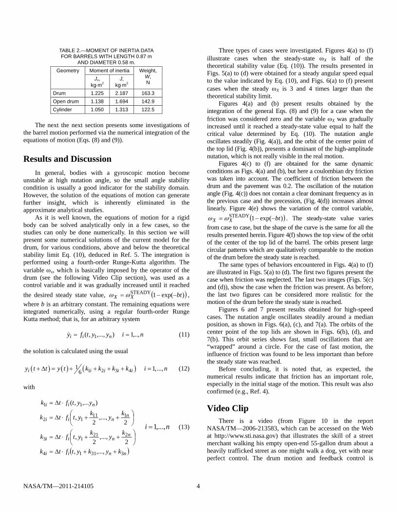
TABLE 2.—MOMENT OF INERTIA DATA FOR BARRELS WITH LENGTH 0.87 m
AND DIAMETER 0.58 m.
Geometry Moment of inertia Weight, W, N
Jx, kgm2
J, kgm2
Drum 1.225 2.187 163.3
Open drum 1.138 1.694 142.9
Cylinder 1.050 1.313 122.5
The next the next section presents some investigations of
the barrel motion performed via the numerical integration of the equations of motion (Eqs. (8) and (9)).
Results and Discussion
In general, bodies with a gyroscopic motion become unstable at high nutation angle, so the small angle stability condition is usually a good indicator for the stability domain. However, the solution of the equations of motion can generate further insight, which is inherently eliminated in the approximate analytical studies.
As it is well known, the equations of motion for a rigid body can be solved analytically only in a few cases, so the studies can only be done numerically. In this section we will present some numerical solutions of the current model for the drum, for various conditions, above and below the theoretical stability limit Eq. (10), deduced in Ref. 5. The integration is performed using a fourth-order Runge-Kutta algorithm. The variable x, which is basically imposed by the operator of the drum (see the following Video Clip section), was used as a control variable and it was gradually increased until it reached the desired steady state value, )exp(1STEADY btXX , where b is an arbitrary constant. The remaining equations were integrated numerically, using a regular fourth-order Runge Kutta method; that is, for an arbitrary system
niyytfy nii ,..,1 ),...,,( 1 (11)
the solution is calculated using the usual
1 2 3 416 1,...,i i i i iy t t y t k k k k i n (12)
with
nnii
nnii
nnii
nii
kykytftk
kykytftk
kykytftk
yytftk
33114
22113
11112
11
,...,,2
,...,2
,
2,...,
2,
),...,(
ni ,...,1 (13)
Three types of cases were investigated. Figures 4(a) to (f) illustrate cases when the steady-state X is half of the theoretical stability value (Eq. (10)). The results presented in Figs. 5(a) to (d) were obtained for a steady angular speed equal to the value indicated by Eq. (10), and Figs. 6(a) to (f) present cases when the steady X is 3 and 4 times larger than the theoretical stability limit.
Figures 4(a) and (b) present results obtained by the integration of the general Eqs. (8) and (9) for a case when the friction was considered zero and the variable X was gradually increased until it reached a steady-state value equal to half the critical value determined by Eq. (10). The nutation angle oscillates steadily (Fig. 4(a)), and the orbit of the center point of the top lid (Fig. 4(b)), presents a dominant of the high-amplitude nutation, which is not really visible in the real motion.
Figures 4(c) to (f) are obtained for the same dynamic conditions as Figs. 4(a) and (b), but here a coulombian dry friction was taken into account. The coefficient of friction between the drum and the pavement was 0.2. The oscillation of the nutation angle (Fig. 4(c)) does not contain a clear dominant frequency as in the previous case and the precession, (Fig. 4(d)) increases almost linearly. Figure 4(e) shows the variation of the control variable,
)exp(1STEADY btXX . The steady-state value varies from case to case, but the shape of the curve is the same for all the results presented herein. Figure 4(f) shows the top view of the orbit of the center of the top lid of the barrel. The orbits present large circular patterns which are qualitatively comparable to the motion of the drum before the steady state is reached.
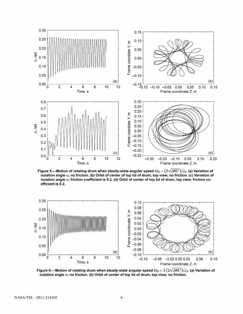
The same types of behaviors encountered in Figs. 4(a) to (f) are illustrated in Figs. 5(a) to (d). The first two figures present the case when friction was neglected. The last two images (Figs. 5(c) and (d)), show the case when the friction was present. As before, the last two figures can be considered more realistic for the motion of the drum before the steady state is reached.
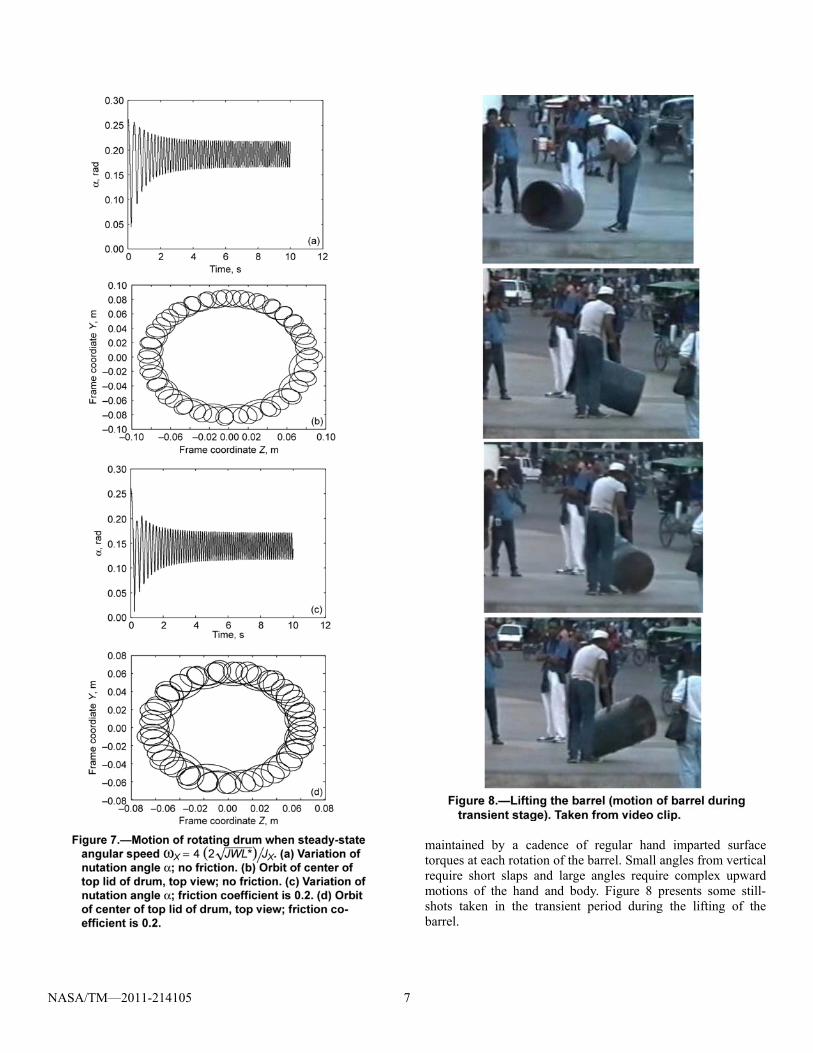
Figures 6 and 7 present results obtained for high-speed cases. The nutation angle oscillates steadily around a median position, as shown in Figs. 6(a), (c), and 7(a). The orbits of the center point of the top lids are shown in Figs. 6(b), (d), and 7(b). This orbit series shows fast, small oscillations that are “wrapped” around a circle. For the case of fast motion, the influence of friction was found to be less important than before the steady state was reached.
Before concluding, it is noted that, as expected, the numerical results indicate that friction has an important role, especially in the initial stage of the motion. This result was also confirmed (e.g., Ref. 4).
Video Clip There is a video (from Figure 10 in the report
NASA/TM—2006-213583, which can be accessed on the Web at http://www.sti.nasa.gov) that illustrates the skill of a street merchant walking his empty open-end 55-gallon drum about a heavily trafficked street as one might walk a dog, yet with near perfect control. The drum motion and feedback control is

NASA/TM—2011-214105 5
NASA/TM—2011-214105 6
NASA/TM—2011-214105 7
maintained by a cadence of regular hand imparted surface torques at each rotation of the barrel. Small angles from vertical require short slaps and large angles require complex upward motions of the hand and body. Figure 8 presents some still-shots taken in the transient period during the lifting of the barrel.

NASA/TM—2011-214105 8
Conclusions
The dynamic motion of a drum about its center of mass that is restrained by a plane normal to the axis of rotation passing through its center of mass at an angle α is both entertaining and instructive. The first part of this paper presented some analytical considerations regarding the stability of such a barrel. Here, some aspects of the motion using the numerical solution of the equations of motion were discussed. The numerical results, obtained both above and below the theoretical stability limit, confirm the validity of the analytical results obtained in the first part of this work. The numerical results also indicate that friction has an important role, especially in the initial stage of the motion.
References
[1] Banerjee, Arun K.; and Mitiguy, Paul C.: Unified Computation of Stick-Slide FrictionApplication to Rattlebacks, Tops, and Journal Bearings. AIAA19953350, 1995, pp. 16161622.
[2] Caughey, T.K.: A Mathematical Model of the “Rattleback.” Int. J. Non-Linear Mech., vol. 15, 1980, pp. 293302. [3] Kane, Thomas R.; and Levinson, David A.: Realistic Mathematical Modeling of the Rattleback. Int. J. Non-Linear Mech., vol. 17, no. 3, 1982, pp. 175186. [4] Moffatt, H.K.; and Shimomura, Y.: Spinning EggsA Paradox ResolvedAn Explanation for an Odd Egg Performance is Rolled Out in Time for Easter. Nature, vol. 416, issue 6879, 2002, pp. 385386. [5] Moraru, Laurentiu; Dimofte, Florin; and Hendricks, Robert C.: Free Body Dynamics of a Spinning Cylinder With Planar Restraint. Presented at the 3rd International Symposium on Stability Control of Rotating Machinery, paper no. 412, Cleveland, OH, 2005. [6] Thomson, William Tyrell: Introduction to Space Dynamics. Second printing, John Wiley & Sons, New York, NY, 1961.
REPORT DOCUMENTATION PAGE Form Approved OMB No. 0704-0188
The public reporting burden for this collection of information is estimated to average 1 hour per response, including the time for reviewing instructions, searching existing data sources, gathering and maintaining the data needed, and completing and reviewing the collection of information. Send comments regarding this burden estimate or any other aspect of this collection of information, including suggestions for reducing this burden, to Department of Defense, Washington Headquarters Services, Directorate for Information Operations and Reports (0704-0188), 1215 Jefferson Davis Highway, Suite 1204, Arlington, VA 22202-4302. Respondents should be aware that notwithstanding any other provision of law, no person shall be subject to any penalty for failing to comply with a collection of information if it does not display a currently valid OMB control number. PLEASE DO NOT RETURN YOUR FORM TO THE ABOVE ADDRESS.
1. REPORT DATE (DD-MM-YYYY) 01-06-2011
2. REPORT TYPE Technical Memorandum
3. DATES COVERED (From - To)
4. TITLE AND SUBTITLE Free Body Dynamics of a Spinning Cylinder with Planar Restraint-(a.k.a. Barrel of Fun) Part II
5a. CONTRACT NUMBER
5b. GRANT NUMBER
5c. PROGRAM ELEMENT NUMBER
6. AUTHOR(S) Moraru, Laurentiu; Dimofte, Florin; Hendricks, Robert, C.
5d. PROJECT NUMBER
5e. TASK NUMBER
5f. WORK UNIT NUMBER WBS 561581.02.08.03.16.03
7. PERFORMING ORGANIZATION NAME(S) AND ADDRESS(ES) National Aeronautics and Space Administration John H. Glenn Research Center at Lewis Field Cleveland, Ohio 44135-3191
8. PERFORMING ORGANIZATION REPORT NUMBER E-15440-1
9. SPONSORING/MONITORING AGENCY NAME(S) AND ADDRESS(ES) National Aeronautics and Space Administration Washington, DC 20546-0001
10. SPONSORING/MONITOR'S ACRONYM(S) NASA
11. SPONSORING/MONITORING REPORT NUMBER NASA/TM-2011-214105
12. DISTRIBUTION/AVAILABILITY STATEMENT Unclassified-Unlimited Subject Categories: 37, 39, and 70 Available electronically at http://www.sti.nasa.gov This publication is available from the NASA Center for AeroSpace Information, 443-757-5802
13. SUPPLEMENTARY NOTES
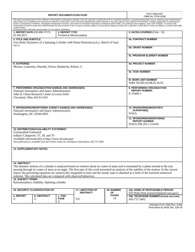
14. ABSTRACT The dynamic motion of a cylinder is analyzed based on rotation about its center of mass and is restrained by a plane normal to the axis passing through its center of mass at an angle. The first part of this work presented an analysis of the stability of the motion. In the current report, the governing equations are numerically integrated in time and the steady state is obtained as a limit of the transient numerical solution. The calculated data are compared with observed behaviors. 15. SUBJECT TERMS Rotordynamics; Stability; Spinning cylinder
16. SECURITY CLASSIFICATION OF: 17. LIMITATION OF ABSTRACT UU
18. NUMBER OF PAGES
14
19a. NAME OF RESPONSIBLE PERSON STI Help Desk (email:[email protected])
a. REPORT U
b. ABSTRACT U
c. THIS PAGE U
19b. TELEPHONE NUMBER (include area code) 443-757-5802
Standard Form 298 (Rev. 8-98)Prescribed by ANSI Std. Z39-18

