frdm-33931-evb evaluation board - nxp semiconductors · the frdm-33931-evb evaluation board (evb)...
TRANSCRIPT

Freescale Semiconductor, Inc.User’s Guide
© Freescale Semiconductor, Inc., 2015. All rights reserved.
Document Number: KTFRDM33931UGRev. 1.0, 7/2015
FRDM-33931-EVB Evaluation Board
Figure 1. FRDM-33931-EVB

KTFRDM33931UG Rev. 1.02 Freescale Semiconductor, Inc.
Table of Contents
1 Important Notice . . . . . . . . . . . . . . . . . . . . . . . . . . . . . . . . . . . . . . . . . . . . . . . . . . . . . . . . . . . . . . . . . . . . . . . . . . . . . . . . . . . . . . . . . 32 Getting Started. . . . . . . . . . . . . . . . . . . . . . . . . . . . . . . . . . . . . . . . . . . . . . . . . . . . . . . . . . . . . . . . . . . . . . . . . . . . . . . . . . . . . . . . . . . 43 Getting to Know the Hardware. . . . . . . . . . . . . . . . . . . . . . . . . . . . . . . . . . . . . . . . . . . . . . . . . . . . . . . . . . . . . . . . . . . . . . . . . . . . . . . 54 FRDM-KL25Z Freedom Development Platform. . . . . . . . . . . . . . . . . . . . . . . . . . . . . . . . . . . . . . . . . . . . . . . . . . . . . . . . . . . . . . . . . 145 Setting up the Hardware and the Graphical User Interface (GUI) . . . . . . . . . . . . . . . . . . . . . . . . . . . . . . . . . . . . . . . . . . . . . . . . . . . 186 Schematic . . . . . . . . . . . . . . . . . . . . . . . . . . . . . . . . . . . . . . . . . . . . . . . . . . . . . . . . . . . . . . . . . . . . . . . . . . . . . . . . . . . . . . . . . . . . . 307 Board Layout . . . . . . . . . . . . . . . . . . . . . . . . . . . . . . . . . . . . . . . . . . . . . . . . . . . . . . . . . . . . . . . . . . . . . . . . . . . . . . . . . . . . . . . . . . . 318 Board Bill of Materials . . . . . . . . . . . . . . . . . . . . . . . . . . . . . . . . . . . . . . . . . . . . . . . . . . . . . . . . . . . . . . . . . . . . . . . . . . . . . . . . . . . . 329 Accessory Item Bill of Materials . . . . . . . . . . . . . . . . . . . . . . . . . . . . . . . . . . . . . . . . . . . . . . . . . . . . . . . . . . . . . . . . . . . . . . . . . . . . . 3410 References . . . . . . . . . . . . . . . . . . . . . . . . . . . . . . . . . . . . . . . . . . . . . . . . . . . . . . . . . . . . . . . . . . . . . . . . . . . . . . . . . . . . . . . . . . . . 3511 Revision History . . . . . . . . . . . . . . . . . . . . . . . . . . . . . . . . . . . . . . . . . . . . . . . . . . . . . . . . . . . . . . . . . . . . . . . . . . . . . . . . . . . . . . . . . 36

Important Notice
KTFRDM33931UG Rev. 1.0 Freescale Semiconductor, Inc. 3
1 Important NoticeFreescale provides the enclosed product(s) under the following conditions:
This evaluation kit is intended for use of ENGINEERING DEVELOPMENT OR EVALUATION PURPOSES ONLY. It is provided as a sample IC pre-soldered to a printed circuit board to make it easier to access inputs, outputs, and supply terminals. This evaluation board may be used with any development system or other source of I/O signals by simply connecting it to the host MCU or computer board via off-the-shelf cables. This evaluation board is not a Reference Design and is not intended to represent a final design recommendation for any particular application. Final device in an application will be heavily dependent on proper printed circuit board layout and heat sinking design as well as attention to supply filtering, transient suppression, and I/O signal quality.
The goods provided may not be complete in terms of required design, marketing, and or manufacturing related protective considerations, including product safety measures typically found in the end product incorporating the goods. Due to the open construction of the product, it is the user's responsibility to take any and all appropriate precautions with regard to electrostatic discharge. In order to minimize risks associated with the customers applications, adequate design and operating safeguards must be provided by the customer to minimize inherent or procedural hazards. For any safety concerns, contact Freescale sales and technical support services.
Should this evaluation kit not meet the specifications indicated in the kit, it may be returned within 30 days from the date of delivery and will be replaced by a new kit.
Freescale reserves the right to make changes without further notice to any products herein. Freescale makes no warranty, representation or guarantee regarding the suitability of its products for any particular purpose, nor does Freescale assume any liability arising out of the application or use of any product or circuit, and specifically disclaims any and all liability, including without limitation consequential or incidental damages. “Typical” parameters can and do vary in different applications and actual performance may vary over time. All operating parameters, including “Typical”, must be validated for each customer application by customer’s technical experts.
Freescale does not convey any license under its patent rights nor the rights of others. Freescale products are not designed, intended, or authorized for use as components in systems intended for surgical implant into the body, or other applications intended to support or sustain life, or for any other application in which the failure of the Freescale product could create a situation where personal injury or death may occur.
Should the Buyer purchase or use Freescale products for any such unintended or unauthorized application, the Buyer shall indemnify and hold Freescale and its officers, employees, subsidiaries, affiliates, and distributors harmless against all claims, costs, damages, and expenses, and reasonable attorney fees arising out of, directly or indirectly, any claim of personal injury or death associated with such unintended or unauthorized use, even if such claim alleges Freescale was negligent regarding the design or manufacture of the part.Freescale™ and the Freescale logo are trademarks of Freescale Semiconductor, Inc. All other product or service names are the property of their respective owners. © Freescale Semiconductor, Inc. 2015

Getting Started
KTFRDM33931UG Rev. 1.04 Freescale Semiconductor, Inc.
2 Getting Started
2.1 Kit Contents/Packing ListThe FRDM-33931-EVB contents include:
• Assembled and tested evaluation board/module in anti-static bag• Warranty card
2.2 Jump StartFreescale’s analog product development boards provide an easy-to-use platform for evaluating Freescale products. They support a range of analog, mixed-signal and power solutions. The boards incorporate monolithic ICs and system-in-package devices that use proven high-volume SMARTMOS technology. Freescale products enable longer battery life, smaller form factor, component count reduction, ease of design, lower system cost and improved performance in powering state of the art systems.
All product development boards are accompanied by a Jump Start bundle available on the board’s Tool Summary Page. Jump Start bundles offer the most current version of the resources that support the development board. The bundles contain everything you need to begin using the Freescale development board in your environment.
To access the Jump Start bundle for the FRDM-33931-EVB:• Go to www.freescale.com/FRDM-33931-EVB• Review your Tool Summary Page• Look for
• Download the documents, software and other resources
2.3 Required Equipment and Software To use this kit, you need:
• DC Power supply: 5.0 V to 40 V with up to 10 A current handling capability, depending on motor requirements.• USB Standard A (male) to mini-B (male) cable• Typical loads (brushed DC motor, power resistors or inductive load with up to 5.0 A and 28 V operation)• Function generator (optional)• FRDM-KL25Z Freedom Development Platform (optional)• ARM®mbed™ firmware loaded on FRDM-KL25Z board (To compile the code, you need to have an account in www.mbed.org.)• MC33931 microcode loaded on FRDM-KL25Z• Graphical User Interface required for use with FRDM-KL25Z
2.4 System RequirementsThe kit requires the following to function properly with the software:
• A USB enabled computer with Windows® XP or later (required only if FRDM-KL25Z is used)
Jump Start Your Design

Getting to Know the Hardware
KTFRDM33931UG Rev. 1.0 Freescale Semiconductor, Inc. 5
3 Getting to Know the Hardware
3.1 Board OverviewThe FRDM-33931-EVB Evaluation Board (EVB) provides a development platform that exercises all the functions of the MC33931 H-bridge IC. The EVB is designed for use in conjunction with the FRDM-KL25Z board (not included with the evaluation board). In this configuration, the FRDM-KL25Z must be prepped and the hardware configured as described in Section 5. To control the MCU outputs, use the graphical user interface “GUI Brushed DC FRDM-33931-EVB” available on Freescale’s website. Alternatively, the EVB can be used without the FRDM-KL25Z, in which case the parallel inputs in the device must be controlled through 3.3/5.0 V compatible GPIO of the MCU or by connecting the board to a function generator.
3.2 Board FeaturesThe board allows evaluation of Freescale part MC33931 and all its functions. The board features the following:
• Compatibility with Freescale's Freedom Development Platform• Built in reverse battery protection• Test points to allow signal probing• Built in voltage regulator to supply logic level circuitry• LEDs to indicate the supply status and direction of motor• Transient voltage suppressor to handle system level transients
3.3 Block DiagramThe hardware block diagram is shown in Figure 2.
Figure 2. Block Diagram
MC33931
Power Supply
ReverseBattery andTransientProtection
5.0 V VoltageRegulator
VPWRLED
VDD LEDOptional 5.0 V Supply to
FRDMOptional 3.3 V Supply to
FRDMCharge Pump Capacitor
VPWR
CCP
IN1
IN2
EN/D2_b
D2FB
OUT2
OUT1
SF_B
All Grounds
SF_B FlagLED
FWD LED
REV LED
To MCUGPIO
To MCUADC input
LoadFromMCUGPIO

Getting to Know the Hardware
KTFRDM33931UG Rev. 1.06 Freescale Semiconductor, Inc.
3.4 Device FeaturesThis evaluation board features the following Freescale product:
3.5 Operation Modes
Figure 3. Operation Modes
Table 1. MC3491 Device Features
Device Description Features
MC33931The 33931 is a monolithic H-Bridge Power IC in a robust thermally enhanced 32 pin SOIC-EP pack-age.
• 5.0 V to 28 V continuous operation (transient operation from 5.0 V to 40 V)
• 3.0 V and 5.0 V TTL / CMOS logic compatible inputs
• 235 mΩ maximum RDS(on) at TJ = 150 °C (each H-Bridge MOSFET)
• Overcurrent limiting (regulation) via internal constant-off-time PWM
• Output short-circuit protection (short to VPWR or GND)
• Temperature-dependent current-limit threshold reduction
• Sleep mode with current draw < 50 μA

Getting to Know the Hardware
KTFRDM33931UG Rev. 1.0 Freescale Semiconductor, Inc. 7
3.6 Architecture
Figure 4. General Architecture Diagram
3.7 Thermal Management
Figure 5. Thermal Management (Thermal Fold-back)
HS2
LS2
OUT1OUT2
HS1
LS1
PGND
VPWR
CURRENT MIRRORAND
CONSTANT OFF-TIMEPWM CURRENT REGULATOR
PGND
VSENSE
ILIM PWM
TO GATESHS1
HS2
LS1
LS2GATE DRIVEAND
PROTECTIONLOGIC
AGND
CHARGEPUMP
VCPCCP
IN1
IN2EN/D2
D1
SF
FB
AnalogControl andProtection
LOGIC SUPPLYVDD
GateControlLogic
OutputDrivers
Thermal Management
Time
Am
ps
8
7
6
5
4
3
2
1
0
6.5 A
PWM Switching
4.2 A
Thermal Fold Back
Thermal management • PWM switching to 6.5 A at < 165 °C - Below 165 °C, the device PWMs the outputs, averaging under 6.5 A to reduce thermals while continuing operation
• Thermal fold back to 4.2 A at 165 °C < T < 185 °C - Above 165 °C, the device goes into thermal fold back, averaging under 4.2 A to reduce thermals while continuing operation
• Thermal shutdown at 175 °C < T < 200 °C - The device shuts down

Getting to Know the Hardware
KTFRDM33931UG Rev. 1.08 Freescale Semiconductor, Inc.
3.8 Board DescriptionFigure 6 and Table 2 describes the main blocks of the evaluation board.
Figure 6. Board Description
Table 2. Board Description
Name Description
MC33931 Monolithic H-Bridge Power IC in a robust thermally enhanced 32 pin SOIC-EP package
5.0 V Regulator 5.0 V regulator for VDD and supply
Jumpers Jumpers for configuring the board for different modes of operation
Reverse Battery Protection Diode Diode for protecting MC33931 in reverse battery condition
Power and Ground inputs Power supply terminal to connect the battery/power supply with the board
Test Points Test points to probe different signals
Output terminal Output connector to connect a load to the MC33931 output
5 V Regulator
Jumpers
ReverseBatteryProtectionDiode
Power andGroundInputs
Test Points
Test Points
OutputTerminal
MC33931

Getting to Know the Hardware
KTFRDM33931UG Rev. 1.0 Freescale Semiconductor, Inc. 9
3.9 LED DisplayThe following LEDs are provided as visual output devices for the evaluation board:
Figure 7. LED Display
Table 3. LED Display
LED ID Description
D3 YELLOW LED, indicates when main/battery supply is connected
D4 GREEN LED, indicates when +5.0 V supply is connected
D5 RED LED, illuminates when the H-Bridge detects a fault
D6 GREEN LED, indicates current flowing in forward direction
D7 RED LED, indicates current flowing in reverse direction
D6
D7
D5
D3
D4

Getting to Know the Hardware
KTFRDM33931UG Rev. 1.010 Freescale Semiconductor, Inc.
3.10 Jumper DefinitionsFigure 8 shows the jumper locations on the board.
Figure 8. Board Jumpers
The following table defines the evaluation board jumper positions and explains their functions. (The default settings are shown in blue.)
.
Table 4. Jumper Definitions
Jumper Description Setting Connection
JP1 5.0 V Regulator output 1-2 5.0 V regulator connected / External or USB 5.0 V
JP2 VDD Select1-2 3.3 V as VDD
2-3 5.0 V as VDD
JP3 FB 1-2 Feedback to MCU ADC / NC
JP4 D11-2 MCU GPIO
2-3 GND
JP5 EN/D2_B1-2 MCU GPIO
2-3 VDD
JP6 IN1 1-2 MCU GPIO / EXT Signal to IN1
JP7 IN2 1-2 MCU GPIO / EXT Signal to IN2
JP1 JP4
JP2 JP5
JP3 JP6 JP7

Getting to Know the Hardware
KTFRDM33931UG Rev. 1.0 Freescale Semiconductor, Inc. 11
3.11 Input Signal DefinitionThe board has the following input signals which are used to control the outputs or functions inside the circuit.
3.12 Output Signal DefinitionThe board has the following output signals which are used to drive a load such as a brushed DC motor. It provides an analog output for real time load current monitoring. This signal allows closed loop control of the load.
Table 5. Input Signals
Input Name Description
D1 Disable signal to tri-state the outputs (Active High)
EN/D2_b Disable signal to tri-state the output and put the part in sleep mode (Active Low)
IN1 Logic input to control OUT1
IN2 Logic input to control OUT2
Table 6. Output Signals
Output Name Description
OUT1 Output 1 of H-Bridge controlled by the logic input IN1
OUT2 Output 2 of H-Bridge controlled by the logic input IN2
SF_B Open drain Active Low status flag output to indicate fault
FB Current mirror output for real time load current monitoring
Getting to Know the Hardware
KTFRDM33931UG Rev. 1.012 Freescale Semiconductor, Inc.
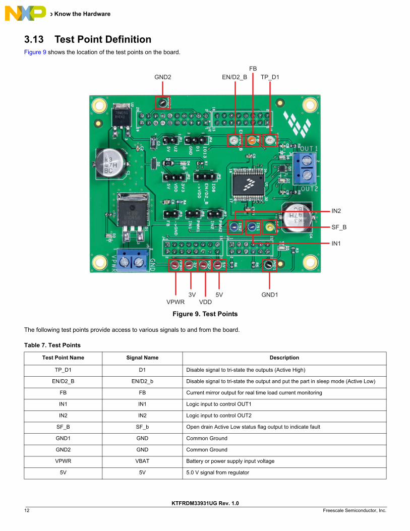
3.13 Test Point DefinitionFigure 9 shows the location of the test points on the board.
Figure 9. Test Points
The following test points provide access to various signals to and from the board.
Table 7. Test Points
Test Point Name Signal Name Description
TP_D1 D1 Disable signal to tri-state the outputs (Active High)
EN/D2_B EN/D2_b Disable signal to tri-state the output and put the part in sleep mode (Active Low)
FB FB Current mirror output for real time load current monitoring
IN1 IN1 Logic input to control OUT1
IN2 IN2 Logic input to control OUT2
SF_B SF_b Open drain Active Low status flag output to indicate fault
GND1 GND Common Ground
GND2 GND Common Ground
VPWR VBAT Battery or power supply input voltage
5V 5V 5.0 V signal from regulator
GND2
SF_B
VPWR3V 5V
VDDGND1
IN2
IN1
EN/D2_BFB
TP_D1

Getting to Know the Hardware
KTFRDM33931UG Rev. 1.0 Freescale Semiconductor, Inc. 13
3.14 Screw Terminal ConnectionsThe board has following screw terminal connections to connect the power supply and the load. Figure 10 shows the location of the screw terminal connectors.
Figure 10. Screw Terminal Connectors
3V 3V3 3.3 V supply from the FRDM board
VDD VDD VDD supply for the FS_B pull-up resistor
Table 8. Screw Terminal Connections
Screw Terminal Name Description
J5 Power supply connector for MC33931
J6 Output connector for connecting to a load
Table 7. Test Points (continued)
Test Point Name Signal Name Description
J5
J6

FRDM-KL25Z Freedom Development Platform
KTFRDM33931UG Rev. 1.014 Freescale Semiconductor, Inc.
4 FRDM-KL25Z Freedom Development PlatformThe Freescale Freedom development platform is a set of software and hardware tools facilitating rapid prototyping of designs based on the Kinetis family of microcontrollers. The Freescale FRDM-KL25Z board serves as the basic hardware component of the development platform. The FRDM-KL25Z implements a Kinetis L Series microcontroller and makes use of the device’s built-in USB, LED, and I/O port features. The board can be loaded with application specific firmware and can be configured with Graphical User Interface software that supports development and testing.
The Freescale FRDM-33931-EVB may be mounted to the FRDM-KL25Z as a shield board. When used in conjunction with the FRDM-33931-EVB, the FRDM-KL25Z provides basic functions, such as PC communication, that support the application-specific features of the evaluation board.
For use with the FRDM-33931-EVB, the FRDM-KL25Z must have ARM®mbed™ firmware installed (see Section 5.2.2, Downloading mbed® Firmware to the FRDM-KL25Z Board), MC33931 microcode installed (see Section 5.2.3, Downloading the MC33931 Microcode to the FRDM-KL25Z Board), and must use the Freescale “GUI Brushed DC FRDM-33931-EVB” as the software interface (see Section 5.2.4, Installing the Graphical User Interface).
For complete information on the FRDM-KL25Z, access the documentation available on the FRDM-KL25Z Tool Summary page.
Figure 11 illustrates the primary components of the FRDM-KL25Z that apply when ‘used in conjunction with the evaluation board.
Figure 11. FRDM-KL25Z Board
J10 I/OHeader
J9 I/OHeader
J1 I/OHeader
J2 I/OHeader
KL25ZUSB
Reset OpenSDAUSB
RGBLED
FRDM-KL25Z Freedom Development Platform
KTFRDM33931UG Rev. 1.0 Freescale Semiconductor, Inc. 15
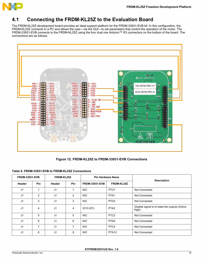
4.1 Connecting the FRDM-KL25Z to the Evaluation BoardThe FRDM-KL25Z development board provides an ideal support platform for the FRDM-33931-EVB kit. In this configuration, the FRDM-KL25Z connects to a PC and allows the user—via the GUI—to set parameters that control the operation of the motor. The FRDM-33931-EVB connects to the FRDM-KL25Z using the four dual row Arduino™ R3 connectors on the bottom of the board. The connections are as follows:
Figure 12. FRDM-KL25Z to FRDM-33931-EVB Connections
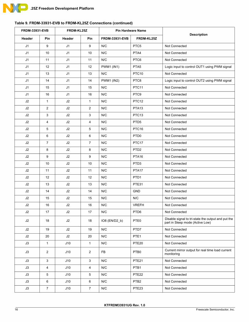
Table 9. FRDM-33931-EVB to FRDM-KL25Z Connections
FRDM-33931-EVB FRDM-KL25Z Pin Hardware NameDescription
Header Pin Header Pin FRDM-33931-EVB FRDM-KL25Z
J1 1 J1 1 N/C PTC7 Not Connected
J1 2 J1 2 N/C PTA1 Not Connected
J1 3 J1 3 N/C PTC0 Not Connected
J1 4 J1 4 IO13 (D1) PTA2Disable signal to tri-state the outputs (Active High)
J1 5 J1 5 N/C PTC3 Not Connected
J1 6 J1 6 N/C PTD4 Not Connected
J1 7 J1 7 N/C PTC4 Not Connected
J1 8 J1 8 N/C PTA12 Not Connected
700-28782-REV X1
SCH-28782-REV A
FRDM-KL25Z Freedom Development Platform
KTFRDM33931UG Rev. 1.016 Freescale Semiconductor, Inc.
J1 9 J1 9 N/C PTC5 Not Connected
J1 10 J1 10 N/C PTA4 Not Connected
J1 11 J1 11 N/C PTC6 Not Connected
J1 12 J1 12 PWM1 (IN1) PTA5 Logic input to control OUT1 using PWM signal
J1 13 J1 13 N/C PTC10 Not Connected
J1 14 J1 14 PWM1 (IN2) PTC8 Logic input to control OUT2 using PWM signal
J1 15 J1 15 N/C PTC11 Not Connected
J1 16 J1 16 N/C PTC9 Not Connected
J2 1 J2 1 N/C PTC12 Not Connected
J2 2 J2 2 N/C PTA13 Not Connected
J2 3 J2 3 N/C PTC13 Not Connected
J2 4 J2 4 N/C PTD5 Not Connected
J2 5 J2 5 N/C PTC16 Not Connected
J2 6 J2 6 N/C PTD0 Not Connected
J2 7 J2 7 N/C PTC17 Not Connected
J2 8 J2 8 N/C PTD2 Not Connected
J2 9 J2 9 N/C PTA16 Not Connected
J2 10 J2 10 N/C PTD3 Not Connected
J2 11 J2 11 N/C PTA17 Not Connected
J2 12 J2 12 N/C PTD1 Not Connected
J2 13 J2 13 N/C PTE31 Not Connected
J2 14 J2 14 N/C GND Not Connected
J2 15 J2 15 N/C N/C Not Connected
J2 16 J2 16 N/C VREFH Not Connected
J2 17 J2 17 N/C PTD6 Not Connected
J2 18 J2 18 IO8 (EN/D2_b) PTE0Disable signal to tri-state the output and put the part in Sleep mode (Active Low)
J2 19 J2 19 N/C PTD7 Not Connected
J2 20 J2 20 N/C PTE1 Not Connected
J3 1 J10 1 N/C PTE20 Not Connected
J3 2 J10 2 FB PTB0Current mirror output for real time load current monitoring
J3 3 J10 3 N/C PTE21 Not Connected
J3 4 J10 4 N/C PTB1 Not Connected
J3 5 J10 5 N/C PTE22 Not Connected
J3 6 J10 6 N/C PTB2 Not Connected
J3 7 J10 7 N/C PTE23 Not Connected
Table 9. FRDM-33931-EVB to FRDM-KL25Z Connections (continued)
FRDM-33931-EVB FRDM-KL25Z Pin Hardware NameDescription
Header Pin Header Pin FRDM-33931-EVB FRDM-KL25Z

FRDM-KL25Z Freedom Development Platform
KTFRDM33931UG Rev. 1.0 Freescale Semiconductor, Inc. 17
J3 8 J10 8 SF_B PTB3Open drain Active Low status flag output to indi-cate fault
J3 9 J10 9 N/C PTE29 Not Connected
J3 10 J10 10 N/C PTC2 Not Connected
J3 11 J10 11 N/C PTE30 Not Connected
J3 12 J10 12 N/C PTC1 Not Connected
J4 1 J9 1 N/C PTB8 Not Connected
J4 2 J9 2 N/C SDA_PTD5 Not Connected
J4 3 J9 3 N/C PTB9 Not Connected
J4 4 J9 4 N/C P3V3 Not Connected
J4 5 J9 5 N/C PTB10 Not Connected
J4 6 J9 6 N/C RESET/PTA20 Not Connected
J4 7 J9 7 N/C PTB11 Not Connected
J4 8 J9 8 FSD 3V3 OUT P3V33.3 V logic output from FRDM-KL25Z board to FRDM34931S-EVB
J4 9 J9 9 N/C PTE2 Not Connected
J4 10 J9 10 N/C P5V_USB Not Connected
J4 11 J9 11 N/C PTE3 Not Connected
J4 12 J9 12 GND GND Not Connected
J4 13 J9 13 N/C PTE4 Not Connected
J4 14 J9 14 N/C GND Not Connected
J4 15 J9 15 N/C PTE5 Not Connected
J4 16 J9 16 FSD 5V IN P5-9V_VIN5.0 V logic input to FRDM-KL25Z board from FRDM-34931S-EVB
Table 9. FRDM-33931-EVB to FRDM-KL25Z Connections (continued)
FRDM-33931-EVB FRDM-KL25Z Pin Hardware NameDescription
Header Pin Header Pin FRDM-33931-EVB FRDM-KL25Z

Setting up the Hardware and the Graphical User Interface (GUI)
KTFRDM33931UG Rev. 1.018 Freescale Semiconductor, Inc.
5 Setting up the Hardware and the Graphical User Interface (GUI)
The evaluation board is designed to work in conjunction with Freescale’s FRDM-KL25Z board with the PC-based GUI providing direct access to the MC33931 MCU for testing and analysis. Alternatively, the board may be used as a stand-alone component, in which case lab hardware, such as a function generator, must be used to support testing and analysis.
The evaluation board consists of an H-bridge, a parallel interface, power conditioning circuitry, and a set of two Input Select jumpers. All +5.0 V VDD power required by the board is obtained via the parallel interface.
Caution:
To avoid damaging the board, the following restrictions must be observed:
• The motor supply voltage (VPWR) must be at least 5.0 V, but must not exceed 40 V.• The peak operating current of the load must not exceed 5.0 A.
5.1 Setting up the FRDM-33931-EVB as a Stand-alone Component
This section describes how to configure the FRDM-33931-EVB for use as a stand-alone component. The procedure assumes that you are using a four-channel function generator to do testing and analysis. The same connections apply if the board is connected to a microcontroller instead of a function generator. Consult the board description (Section 3), the schematic (Section 6), and the MC33931 datasheet to determine how best to configure the board for use in your environment.
1. Connect the function generator to the board. There are two options:
• use the function generator to control the enabling and disabling of the MC33931 H-bridge outputs (Option 1)
• set the the H-bridge outputs to be continuously enabled while the board is connected to the function generator (Option 2).
Figure 13 illustrates how to set the jumpers and connect to a function generator (or an MCU) for each of these options.
2. With the power switched off, attach the DC power supply to the VPWR and GND screw connector terminals on the evaluation board (J5 in Figure 10).
3. Attach one set of coils of the brushed motor to the OUT 1 and OUT 2 screw connector terminals on the evaluation board (J6 in Figure 10).
Figure 13 illustrates the hardware configuration.

Setting up the Hardware and the Graphical User Interface (GUI)
KTFRDM33931UG Rev. 1.0 Freescale Semiconductor, Inc. 19
Figure 13. Hardware Configuration - Stand-alone
Brushed DC MotorFunction Generator (or MCU)
5 - 40 V Power Supply, 10 A
All otherJumpers
set toDefault
Option 1 - Controlled Enabling of Outputs
Brushed DC MotorFunction Generator (or MCU)
5 - 40 V Power Supply, 10 A
JP5 setto 2 - 3
All otherJumpers
set toDefault
Option 2 - Continuous Enabling of Outputs
Setting up the Hardware and the Graphical User Interface (GUI)
KTFRDM33931UG Rev. 1.020 Freescale Semiconductor, Inc.
5.2 Setting up the FRDM-33931-EVB for Use with the FRDM-KL25Z
To configure the evaluation board for use with the FRDM KL25Z and the Graphical User Interface (GUI) you must:• Connect the hardware• Download the mbed firmware to the FRDM-KL25Z board• Download the MC33931 microcode to the FRDM-KL25Z board• Install the Graphical User Interface “GUI Brushed DC FRDM-33931-EVB”
5.2.1 Connecting the HardwareThe FRDM-33931-EVB consists of an H-bridge, a parallel interface, power conditioning circuitry, and a set of two Input Select jumpers. All +5.0 V VDD power required by the board is obtained via the parallel interface.
WARNINGTo avoid damaging the board, the following restrictions must be observed:
• The motor supply voltage (VPWR) must be at least 5.0 V, but must not exceed 40 V.• The peak operating current of the load must not exceed 5.0 A.
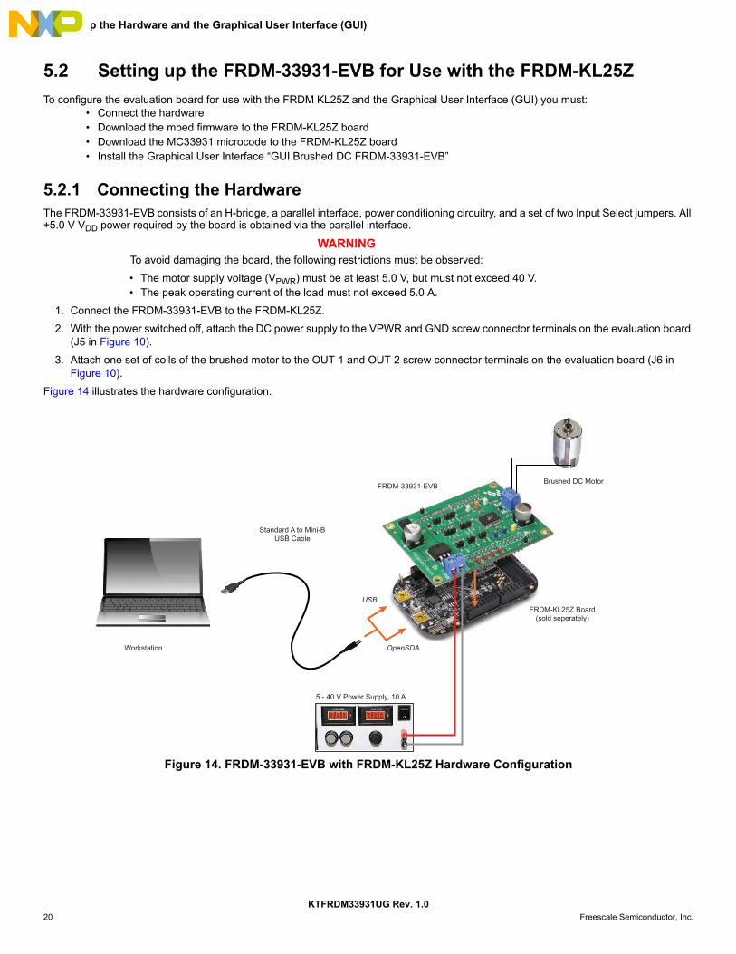
1. Connect the FRDM-33931-EVB to the FRDM-KL25Z.
2. With the power switched off, attach the DC power supply to the VPWR and GND screw connector terminals on the evaluation board (J5 in Figure 10).
3. Attach one set of coils of the brushed motor to the OUT 1 and OUT 2 screw connector terminals on the evaluation board (J6 in Figure 10).
Figure 14 illustrates the hardware configuration.
Figure 14. FRDM-33931-EVB with FRDM-KL25Z Hardware Configuration
FRDM-KL25Z Board(sold seperately)
FRDM-33931-EVBBrushed DC Motor
5 - 40 V Power Supply, 10 A
Workstation
Standard A to Mini-BUSB Cable
USB
OpenSDA

Setting up the Hardware and the Graphical User Interface (GUI)
KTFRDM33931UG Rev. 1.0 Freescale Semiconductor, Inc. 21
5.2.2 Downloading mbed® Firmware to the FRDM-KL25Z BoardYou must install mbed® firmware on the FRDM-KL25Z board to enable downloading of the MC33931 microcode. The procedure is as follows:
1. Connect the USB cable between your PC and the OpenSDA port on the FRDM-KL25Z board.
2. Download the mbed firmware onto the FRDM-KL25Z board. The instructions are on the ARM®mbed™ website at the following url: https://developer.mbed.org/handbook/Firmware-FRDM-KL25Z
3. After downloading the mbed firmware, power cycle the board (by disconnecting then reconnecting the USB cable to the OpenSDA port) to initiate the firmware update. When this process completes, a USB drive named “mbed” should appear on your PC.
5.2.3 Downloading the MC33931 Microcode to the FRDM-KL25Z BoardThe MC33931 microcode provides the firmware interface between the MC33931 device, the Freedom platform and the GUI. The procedure is as follows:
1. Connect the USB cable between your PC and the OpenSDA port on the FRDM-KL25Z board.
2. Go to https://developer.mbed.org/teams/Freescale/code/Brushed_DC_Motor_Control_MC34931_MC33931/ then click on the Import this Program tab.
Figure 15. MC33931/MC33931 mbed Import Screen
1. Go to: developer.mbed.org/teams/Freescale/code/ Brushed_DC_Motor_Control_MC34931_MC33931/
2. Click Import this program

Setting up the Hardware and the Graphical User Interface (GUI)
KTFRDM33931UG Rev. 1.022 Freescale Semiconductor, Inc.
3. Login to your mbed account. (If you do not have an mbed account, you must create one.) After logging in, you will be returned to the screen in Figure 15. Click on Import this program again.
Figure 16. mbed Login Screen
4. The mbed compiler opens with the Import Program window displayed. Click on the “Import” button.
Figure 17. mbed Compiler Import Program Screen
1. Enter your Username and Password2. Click Login
1. Click Import

Setting up the Hardware and the Graphical User Interface (GUI)
KTFRDM33931UG Rev. 1.0 Freescale Semiconductor, Inc. 23
5. When the import completes, the mbed compiler screen should look like Figure 18. Click on the “main.cpp” item.
Figure 18. mbed Compiler Select Screen
6. The source code for main.cpp appears in the code editor. Click on the “Compile” button to compile the main.cpp source code.
Figure 19. mbed Compiler New Program Screen
1. Click on main.cpp
1. Click on Compile

Setting up the Hardware and the Graphical User Interface (GUI)
KTFRDM33931UG Rev. 1.024 Freescale Semiconductor, Inc.
7. When the compiler completes, an executable file named “Brushed_DC_Motor_Control_MC33931_MC33931_KL25Z.bin” downloads to your system download folder. Drag and drop this file to the mbed device which appears as a USB drive on your system.
Figure 20. Downloading Brushed_DC_Motor_Control_MC33931_KL25Z.bin to FRDM-KL25Z
8. Remove the USB connector from the FRDM-KL25Z OpenSDA USB port and insert it in the KL25Z USB port.
The KL25Z board is now ready for use with the FRDM-33931S-EVB and the GUI.
5.2.4 Installing the Graphical User InterfaceThe Graphical User Interface provides a PC-based interface allowing you to easily exercise FRDM-33931-EVB functions to control a DC Brushed Motor. The GUI runs on any Windows 8, Windows 7, Vista, or XP-based operating system at a maximum PWM frequency of 10 kHZ.
To install the software:
1. Go to the evaluation board Tool Summary Page www.freescale.com/FRDM-33931-EVB
2. Under “Jump Start Your Design,” click on the “Get Started with the FRDM-33931-EVB” link.
3. From the list of files that appear, click on the link for the “GUI Brushed DC FRDM-33931-EVB” software.
The software automatically downloads to your PC and initiates the installation process. An Installation Wizard guides you through the rest of the process.
5.2.5 Using the Graphical User InterfaceTo start the GUI, do the following:
1. Connect the hardware (Section 5.2.1, Connecting the Hardware) and plug the USB cable into the USB port on the FRDM-KL25Z.
2. Click on the Freescale GUI Brushed DC FRDM-33931-EVB icon to launch the GUI.
3. Make sure the GUI recognizes the FRDM-KL25Z. Check the USB connection in the upper left corner of the GUI.
• The hex Vendor ID value should display as 0x15A2 and the Part ID value should display as 0x138. • If these value do not appear, the GUI has failed to establish a connection with the FRDM-KL25Z. You may need to disconnect
and reconnect the USB cable to the board’s KL25Z USB port. If the connection still fails, press the reset button on the FRDM-KL25Z board.
4. Click the Enable Target checkbox on the GUI screen. The Target parameter on the GUI screen should change from “DISABLED” to “ENABLED.”
1. Drag and Drop

Setting up the Hardware and the Graphical User Interface (GUI)
KTFRDM33931UG Rev. 1.0 Freescale Semiconductor, Inc. 25
5. Set the DI, EN/D2_B, Direction and Braking as desired (See Section 5.2.6 - Section 5.2.9.) Adjust the PWM Frequency and Duty Cycle to meet your requirements.
6. Click the Run button to run the motor. Notice that some options of the GUI are disabled while the motor is running. To make changes, click the Stop button on the GUI, make the desired changes, and then click “Run” on the GUI to continue.
7. When finished, deselect the “Enable Target” button on the GUI, and click the Quit button. Turn off DC power supply and remove the USB cable.
The GUI is shown in Figure 21. The hex address numbers at the top are loaded with the vendor ID for Freescale (0x15A2), and the part ID (0x138). The left side panel displays these numbers only if the PC is communicating with the FRDM-KL25Z via the USB interface.
Figure 21. GUI Screen
Feedback Current(FB pin out)
Status Fault(SF_b pin out)
Setting up the Hardware and the Graphical User Interface (GUI)
KTFRDM33931UG Rev. 1.026 Freescale Semiconductor, Inc.
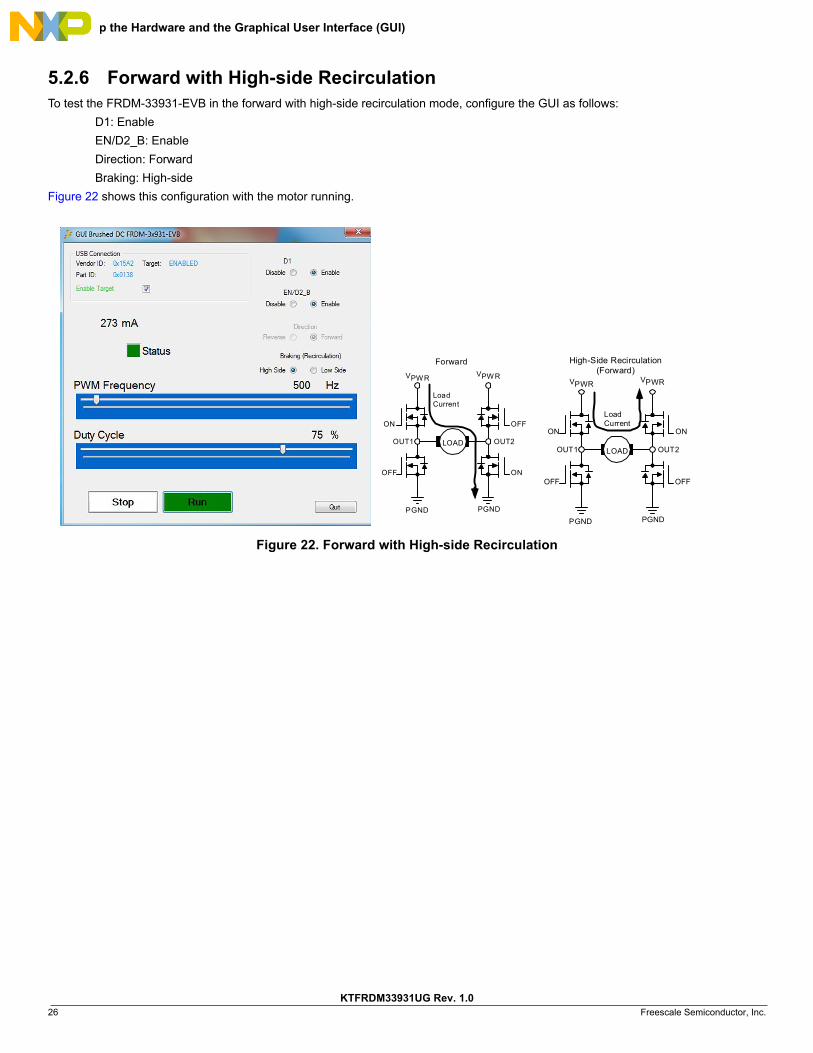
5.2.6 Forward with High-side RecirculationTo test the FRDM-33931-EVB in the forward with high-side recirculation mode, configure the GUI as follows:
D1: Enable
EN/D2_B: Enable
Direction: Forward
Braking: High-side
Figure 22 shows this configuration with the motor running.
Figure 22. Forward with High-side Recirculation
2TUO1TUO
PGND
VPWR VPW R
PGND
LOAD
LoadCurrent
Forward
OFF
ON
ON
OFF
2TUO1TUO
PGND
VPWR VPWR
PGND
LOAD
LoadCurrent
High-Side Recirculation(Forward)
ON
OFF
ON
OFF

Setting up the Hardware and the Graphical User Interface (GUI)
KTFRDM33931UG Rev. 1.0 Freescale Semiconductor, Inc. 27
5.2.7 Forward with Low-side RecirculationTo test the FRDM-33931-EVB in the forward with low-side recirculation mode, configure the GUI as follows:
D1: Enable
EN/D2_B: Enable
Direction: Forward
Braking: Low-side
Figure 23 shows this configuration with the motor running.
Figure 23. Forward with Low-side Recirculation
2TUO1TUO
PGND
VPWR VPWR
PGND
LOAD
LoadCurrent
Low-Side Recirculation(Forward)
NONO
FFOFFO2TUO1TUO
PGND
VPWR VPW R
PGND
LOAD
LoadCurrent
Forward
OFF
ON
ON
OFF

Setting up the Hardware and the Graphical User Interface (GUI)
KTFRDM33931UG Rev. 1.028 Freescale Semiconductor, Inc.
5.2.8 Reverse with High-side RecirculationTo test the FRDM-33931-EVB in the reverse with high-side recirculation mode, configure the GUI as follows:
D1: Enable
EN/D2_B: Enable
Direction: Reverse
Braking: High-side
Figure 24 shows this configuration with the motor running.
Figure 24. Reverse with High-side Recirculation
2TUO1TUO
PGND
VPWR VPWR
PGND
LOAD
LoadCurrent
High-Side Recirculation(Reverse)
ON
OFF
ON
OFF
2TUO1TUO
PGND
OFF
ON
ON
OFF
VPWR VPW R
PGND
LOAD
LoadCurrent
Reverse
Setting up the Hardware and the Graphical User Interface (GUI)
KTFRDM33931UG Rev. 1.0 Freescale Semiconductor, Inc. 29
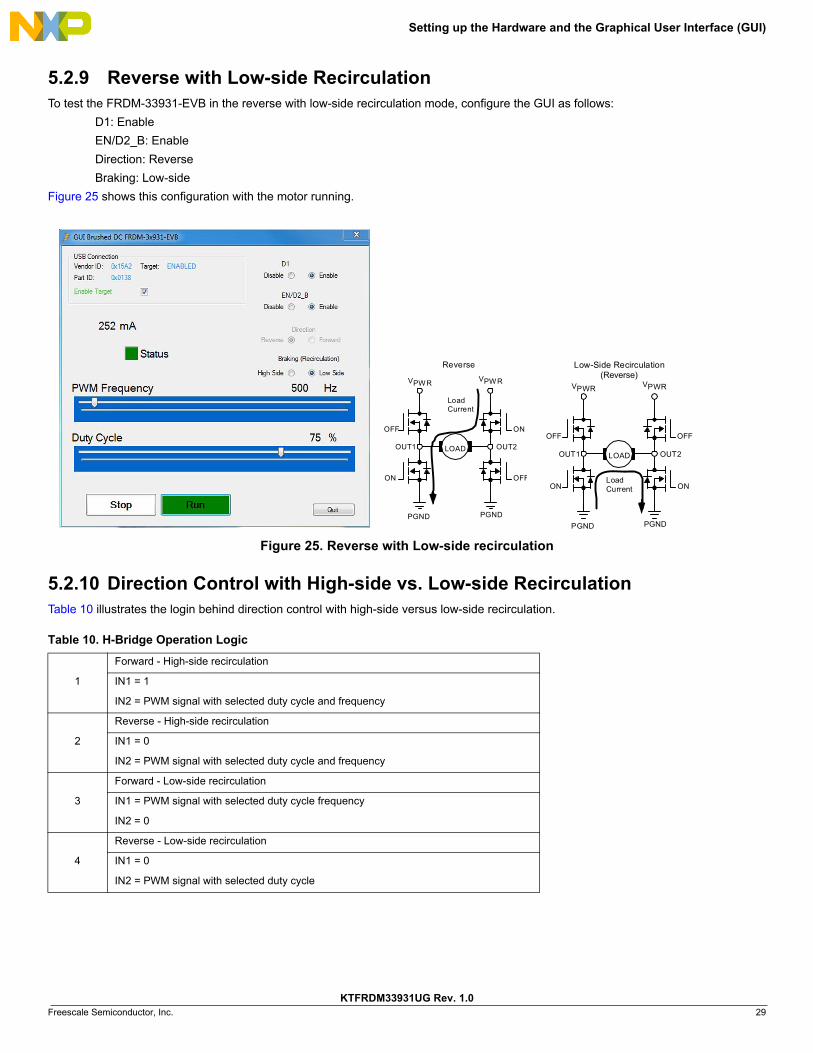
5.2.9 Reverse with Low-side RecirculationTo test the FRDM-33931-EVB in the reverse with low-side recirculation mode, configure the GUI as follows:
D1: Enable
EN/D2_B: Enable
Direction: Reverse
Braking: Low-side
Figure 25 shows this configuration with the motor running.
Figure 25. Reverse with Low-side recirculation
5.2.10 Direction Control with High-side vs. Low-side RecirculationTable 10 illustrates the login behind direction control with high-side versus low-side recirculation.
Table 10. H-Bridge Operation Logic
1
Forward - High-side recirculation
IN1 = 1
IN2 = PWM signal with selected duty cycle and frequency
2
Reverse - High-side recirculation
IN1 = 0
IN2 = PWM signal with selected duty cycle and frequency
3
Forward - Low-side recirculation
IN1 = PWM signal with selected duty cycle frequency
IN2 = 0
4
Reverse - Low-side recirculation
IN1 = 0
IN2 = PWM signal with selected duty cycle
2TUO1TUO
PGND
VPWR VPWR
PGND
LOAD
LoadCurrent
Low-Side Recirculation(Reverse)
NONO
FFOFFO2TUO1TUO
PGND
OFF
ON
ON
OFF
VPWR VPW R
PGND
LOAD
LoadCurrent
Reverse

Schematic
KTFRDM33931UG Rev. 1.030 Freescale Semiconductor, Inc.
6 Schematic
Figure 26. Schematic
(---) External signal on PIN 2
(1-2) Signal from micro
(2-3) VDD
(---) External signal on PIN 2
(1-2) Signal from micro
(2-3) GND
D1 SELECT
EN/D2_B SELECT
(1-2) On-board 5V
(---) External signal on PIN 2 or FSD USB 5V
POWER SUPPLY REGULATOR
(---) External signal on PIN 2
(1-2) Signal from micro
IN1 SELECT
(---) External signal on PIN 2
(1-2) Signal from micro
IN2 SELECT
MC33931
JUMPERS
CONNECTORS
(1-2) 3V3 as VDD
(---) External VDD on PIN 2
(2-3) 5V as VDD
VDD SELECT
5V SELECT
(1) VPWR
POWER INPUT
(2) GND
TEST POINTS
FSD
3V3
OUT
FSD
5V
IN
MCU
FRDM INTERFACE
OUT1/2 CONN
(1-2) Disable
(---) Enable
FB SELECT
MOUNTING HOLES
(1) OUT2
(2) OUT1
https://developer.mbed.org/teams/Freescale/wiki/FRDM-connector-pin-assignments
Pin assignments match FRDM-Type A. Refer to the
Freescale mbed wiki for a list of compatible FRDM
boards.
IO13
OU
T2O
UT1
D1
IO8
EN/D
2_B
PWM
1IN
1
IN2
IN1
PWM
2IN
2
D1
EN/D
2_B
SF_B
PWM
2
SF_B
D1
EN/D
2_B
IN1
IN2
FB
OU
T1O
UT2
FB
FB
SF_B
IO14
AN0
PWM
1
IO13
IO8
VBAT
VBAT
VDD
3V3
VBAT
5V
3V3
5V
VDD
VDD
3V3
5V
5V
VDD
J5 OST
TC02
2162
1 2
D7
RED
A C
U1
MC
3393
1EK
/ MC
3493
1EK
/ MC
3493
1SEK
AG
ND
1
VP
WR
28
SF
32E
P33
OU
T2_2
23V
PW
R3
25
PG
ND
317
D1
2
FB3
NC
_24
24
PG
ND
216
NC
_21
21
IN2
29
PG
ND
115
NC
_99
OU
T1_2
11
NC
_12
12O
UT1
_110
NC
_14
14
CC
P28
NC
_20
20
PG
ND
418
VP
WR
426
EN
/D2
5N
C_4
4
NC
_19
19
NC
_27
27
OU
T2_1
22
NC
_30
30IN
131
VP
WR
17
NC
_13
13
NC
_66
JP7
HD
R 1
X2
1 2
BH1
SMTS
O-M
1.6-
2.25
ET
R4
270.
0
D8
BAS7
0TW
-7-F
2
1
3 4
5
6R
71KG
ND
2
EN/D
2_B
+C4
47uF
50V
3V
TP_D
1
R8
10.0
K
D3
YELL
OW
A C
BH4
SMTS
O-M
1.6-
2.25
ET
R9
10.0
K
+C1
47uF
50V
J3 CO
N_2
X6
DN
P
12
346
578
910
1112
VPW
R
R3
4.70
K
C5
0.1u
F50
V
C9
10nF
50V
JP3
HD
R 1
X2
12
R6
0
JP6
HD
R 1
X2
1 2
5V
C2
0.1u
F50
V
D5
RED
A C
JP1
HD
R 1
X2
12
J4 CO
N_2
X8
DN
P
12
346
578
910
1112
1314
1516
R1
1K
D4
LED
GR
EEN
A C
J1 CO
N_2
X8
DN
P 12
34 6
5 78
910
1112
1314
1516
R5
0
C6
0.04
7UF
50V
SF_B
FB
BH2
SMTS
O-M
1.6-
2.25
ET
VDD
JP2
HD
R 1
X3
1 2 3R
2
470
+C3
10U
F10
V
JP5
HD
R 1
X3
1 2 3
D2
SPT0
2-23
6DD
B
2
1
3
J2 CO
N_2
X10
DN
P 12
34 6
5 78
910
1112
1314
1516
1718
1920
IN1
BH3
SMTS
O-M
1.6-
2.25
ET
C8
10nF
50V
U2
MC
78M
05C
DTR
KG
OU
T3
IN1
GND4
J6 OST
TC02
2162
1 2
JP4
HD
R 1
X3
1 2 3
C7
0.03
3UF
50V
D1
MBR
B104
5T4G
34
1
D6
LED
GR
EEN
A C
GN
D1
IN2

Board Layout
KTFRDM33931UG Rev. 1.0 Freescale Semiconductor, Inc. 31
7 Board Layout
7.1 Silkscreen
Figure 27. Silkscreen

Board Bill of Materials
KTFRDM33931UG Rev. 1.032 Freescale Semiconductor, Inc.
8 Board Bill of Materials
Table 11. Bill of Materials (1)
Item Qty Schematic Label Value Description Part NumberAssy Opt
Freescale Components
1 1 U1 Freescale device MC33931 (2)
Voltage Regulator
2 1 U2IC LIN VREG LDO 5 V 0.5 A 35 V DPAK
MC78M05CDTRKG
Diodes
3 1 D1DIODE SCH PWR RECT 10 A 45 V D2PAK
MBRB1045T4G
4 1 D2DIODE DUAL ARRAY 2 A 6-36 V uQFN-2L
SPT02-236DDB
5 1 D3 LED YEL SGL 25 MA SMT 0603 LY Q976-P1S2-36-0-20-R18
6 2 D4, D6 LED GRN SGL 20 MA 0603 LG L29K-G2J1-24-Z
7 2 D5, D7 LED SM RED 0603 ROHS COMPLIANT QTLP600CRTR
8 1 D8DIODE SCH TRIPLE 70 MA 70 V / 200 MW SOT363
BAS70TW-7
Capacitors
9 2 C1, C4 47 µF CAP ALEL 47 μF 50 V 20% AUTO SMD UBC1H470MNS1GS
10 2 C2, C5 0.1 µFCAP CER 0.1 uF 50 V 5% X7R AEC-Q200 0603
C0603C104J5RACAUTO
11 1 C3 10 µF CAP TANT 10 μF 10 V 10% — 3216-18 293D106X9010A2TE31
12 1 C6 0.047 µF CAP CER 0.047 μF 50 V 5% X7R 0805 C0805C473J5RAC
13 1 C7 0.033 µF CAP CER 0.033 μF 50 V 5% X7R 0603 06035C333JAT2A
14 2 C8, C9 0.1 µF CAP CER 0.01 μF 50 V 5% X7R 0603 06035C103JAT2A
Resistors
15 2 R1, R7 1.0 KΩ RES -- 1 KΩ 1/4 W 1% AEC-Q200 0603 ANTISURGE
ESR03EZPF1001
16 1 R2 470 Ω RES MF 470 Ω 1/4 W 5% AEC-Q200 1206
CRCW1206470RJNEA
17 1 R3 4.7 KΩ RES MF 4.7 KΩ 1/4 W 1% AEC-Q200 0603
CRCW06034K70FKEA
18 1 R4 270 Ω RES MF 270.0 Ω 1/10 W 1% 0603 RK73H1JTTD2700F
19 2 R5, R6 0 Ω RES MF ZERO Ω 1/10 W — AEC-Q200 0603
RK73Z1JTTD
20 1 R8, R9 10 KΩ RES MF 10.0 KΩ 1/10 W 1% 0603 RK73H1JTTD1002F

Board Bill of Materials
KTFRDM33931UG Rev. 1.0 Freescale Semiconductor, Inc. 33
Switches, Connectors, Jumpers and Test Points
21 12TP_D1,EN/D2_B, FB, GND1,GND2, IN1,IN2, SF_B, 3V,5V,VPWR,VDD
TEST POINT 40 MIL DRILL 180 MIL
22 4 JP1,JP3,JP6,JP7HDR 1X2 TH 100 MIL SP 338H SN 100L
TSW-102-07-T-S
23 3 JP2,JP4,JP5HDR 1x3 TH 100 MIL SP 343H SN 100L
TSW-103-07-T-S
24 2 J1, J4HDR 2X8 TH 100MIL CTR 338H SN 100L
TSW-108-07-T-D
25 1 J2HDR 2X10 TH 100MIL CTR 343H SN 100L
TSW-110-07-T-D
26 1 J3HDR 2X6 TH 100MIL CTR 338H SN 100L
TSW-106-07-T-D
27 2 J5, J6CON 1X2 TB 5.08 MM SP 406H SN 138L
OSTTC022162
Notes 1. Freescale does not assume liability, endorse, or warrant components from external manufacturers are referenced in circuit drawings or tables.
While Freescale offers component recommendations in this configuration, it is the customer’s responsibility to validate their application.2. Critical components. For critical components, it is vital to use the manufacturer listed.
Table 11. Bill of Materials (1) (continued)
Item Qty Schematic Label Value Description Part NumberAssy Opt

Accessory Item Bill of Materials
KTFRDM33931UG Rev. 1.034 Freescale Semiconductor, Inc.
9 Accessory Item Bill of Materials Table 12. Bill of Materials (3)
Item Qty Part Number Description
1 1 FRDM-KL25Z Freescale Freedom Development Platform for Kinetis KL14/15/24/25 MCUs
Notes 3. Freescale does not assume liability, endorse, or warrant components from external manufacturers are referenced in circuit drawings or tables.
While Freescale offers component recommendations in this configuration, it is the customer’s responsibility to validate their application.

References
KTFRDM33931UG Rev. 1.0 Freescale Semiconductor, Inc. 35
10 ReferencesFollowing are URLs where you can obtain information on related Freescale products and application solutions:
10.1 SupportVisit www.freescale.com/support for a list of phone numbers within your region.
10.2 WarrantyVisit www.freescale.com/warranty to submit a request for tool warranty.
Freescale.com Support Pages
Description URL
FRDM-33931-EVB Tool Summary Page http://www.freescale.com/webapp/sps/site/prod_summary.jsp?code=FRDM-33931-EVB
MC33931 Product Summary Page http://www.freescale.com/webapp/sps/site/prod_summary.jsp?code=MC33931
FRDM-KL25Z Tool Summary Page http://www.freescale.com/webapp/sps/site/prod_summary.jsp?code=FRDM-KL25Z
ARM®mbed™mbed FRDM-KL25Z Upgrade Page
https://mbed.org/handbook/mbed-FRDM-KL25z-Upgrade

Revision History
KTFRDM33931UG Rev. 1.036 Freescale Semiconductor, Inc.
11 Revision History
Revision Date Description of Changes
1.0 7/2015 • Initial Release

Document Number: KTFRDM33931UGRev. 1.0
7/2015
Information in this document is provided solely to enable system and software implementers to use Freescale products.
There are no express or implied copyright licenses granted hereunder to design or fabricate any integrated circuits based
on the information in this document.
Freescale reserves the right to make changes without further notice to any products herein. Freescale makes no
warranty, representation, or guarantee regarding the suitability of its products for any particular purpose, nor does
Freescale assume any liability arising out of the application or use of any product or circuit, and specifically disclaims any
and all liability, including without limitation consequential or incidental damages. “Typical” parameters that may be
provided in Freescale data sheets and/or specifications can and do vary in different applications, and actual performance
may vary over time. All operating parameters, including “typicals,” must be validated for each customer application by
customer’s technical experts. Freescale does not convey any license under its patent rights nor the rights of others.
Freescale sells products pursuant to standard terms and conditions of sale, which can be found at the following address:
freescale.com/SalesTermsandConditions.
Freescale, the Freescale logo and Kinetis are trademarks of Freescale Semiconductor, Inc., Reg. U.S. Pat. & Tm. Off.
SMARTMOS is a trademarks of Freescale Semiconductor, Inc. All other product or service names are the property of
their respective owners. ARM is a registered trademark of ARM Limited (or its subsidiaries) in the EU and/or elsewhere.
mbed is a trademark of ARM Limited (or its subsidiaries) in the EU and/or elsewhere. All rights reserved.
© 2015 Freescale Semiconductor, Inc.
How to Reach Us:Home Page: freescale.com
Web Support: freescale.com/support