framecad manual
DESCRIPTION
FRAMECAD.PROTRANSCRIPT

©2012 FRAMECAD Limited www.framecad.com
November 2012

©2011 FRAMECAD Limited www.framecad.com
Page1
This document has been published for the purpose of providing information of a general nature only.
Further, no guarantee, warranty, or any other form of assurance is given as to the accuracy, currency
or completeness of the information provided.
Accordingly, any reliance on, or use, by you of any information contained within this document for any
purpose whatsoever shall be entirely at your own risk, and any liability to you is expressly disclaimed
to the maximum extent permitted by law.
ALL INFORMATION CONTAINED IN THIS DOCUMENT IS SUBJECT TO CHANGE WITHOUT
NOTICE. THIS DOCUMENT SUPERSEDES ALL PREVIOUS DOCUMENTS.
Intellectual Property Notice FRAMECAD and the FRAMECAD logo are trademarks of FRAMECAD Limited.
Reproduction of this document and all material included herein is prohibited, except with the prior
written consent of FRAMECAD Limited.
Copyright 2012 FRAMECAD Limited.
Confidentiality This document and all material included herein is confidential to FRAMECAD Limited and must not
be disclosed to any other party or used to the detriment of or other than as authorised by FRAMECAD
Limited.
This document and all material included herein shall be returned to FRAMECAD Limited Immediately
upon request.
Disclaimer

FRAMECAD ProDesign User Manual November 2012
©2012 FRAMECAD Limited www.framecad.com
Page2
Basic Table of Contents
1 PREFACE ................................................................................................................................................... 8
2 INTENDED USE OF SOFTWARE .................................................................................................................. 9
3 STANDARD CAD HOT KEYS ..................................................................................................................... 11
4 SUGGESTED BASIC PROCEDURE ............................................................................................................. 12
5 WALL LAYOUTS ...................................................................................................................................... 13
6 TRUSS LAYOUTS ..................................................................................................................................... 43
7 FLOOR LAYOUTS ..................................................................................................................................... 70
8 ROOF LAYOUTS ...................................................................................................................................... 91
9 MISCELLANEOUS .................................................................................................................................. 107
10 COMMAND SUMMARY .................................................................................................................... 112
11 SOME COMMON PROBLEMS ............................................................................................................ 122
12 ENGINEERING STATEMENTS ............................................................................................................. 124

FRAMECAD ProDesign User Manual November 2012
©2012 FRAMECAD Limited www.framecad.com
Page3
Table of Contents
1 PREFACE ................................................................................................................................................... 8
2 INTENDED USE OF SOFTWARE .................................................................................................................. 9
3 STANDARD CAD HOT KEYS ..................................................................................................................... 11
4 SUGGESTED BASIC PROCEDURE ............................................................................................................. 12
5 WALL LAYOUTS ...................................................................................................................................... 13
5.1 NEW LAYOUT DRAWING ............................................................................................................................. 13
5.2 BSET BORDER SETUPS ............................................................................................................................... 13
5.3 COMMAND REFERENCE ............................................................................................................................... 16
5.4 PTF TRACE FRAME .................................................................................................................................... 17
5.5 PANEL EDITING ......................................................................................................................................... 21
5.5.1 PE Panel Extend ............................................................................................................................ 21
5.5.2 PT Panel Trim ............................................................................................................................... 21
5.5.3 IP Inherit Properties ..................................................................................................................... 22
5.5.4 PF Panel Fillet ............................................................................................................................... 22
5.5.5 PJ Panel Join ................................................................................................................................. 22
5.5.6 PC Panel Cut ................................................................................................................................. 23
5.5.7 PS Panel Square ........................................................................................................................... 23
5.5.8 PM Panel Mitre ............................................................................................................................ 23
5.5.9 PL Panel Lengthen ........................................................................................................................ 23
5.5.10 PX Panel Crossing ......................................................................................................................... 24
5.6 INPUTTING OPENINGS................................................................................................................................. 24
5.6.1 UD User Defined Door Input ......................................................................................................... 24
5.6.1 UW User Defined Window Input .................................................................................................. 24
5.7 PSA INSERT A STUD ARRAY ......................................................................................................................... 25
5.8 PIB INSERT BRACING ................................................................................................................................. 26
5.9 PLA PANEL LABELLING ............................................................................................................................... 27
5.10 REF REFERENCE POINTS ............................................................................................................................. 28
5.11 PIC PANEL INTEGRITY CHECK ...................................................................................................................... 29
5.12 PLI LIST FRAME ........................................................................................................................................ 30
5.12.1 Coding a Frame/Beam .................................................................................................................. 30
5.12.2 Listing an Opening ........................................................................................................................ 33
5.12.3 Listing a Brace Panel ..................................................................................................................... 35
5.12.4 Listing a 3D Entity ......................................................................................................................... 35
5.12.5 Listing a Beam ............................................................................................................................... 36
5.12.6 Listing a Reference Point ............................................................................................................... 37
5.13 DIMENSIONING ......................................................................................................................................... 38
5.13.1 DH Dimension Horizontally .......................................................................................................... 38
5.13.2 DV Dimension Vertically ............................................................................................................... 38
5.13.3 DA Dimension Aligned .................................................................................................................. 38
5.13.4 DOH Dimension Ordinates Horizontally ....................................................................................... 38
5.13.5 DOV Dimension Ordinates Vertically ........................................................................................... 39
5.13.6 DL Dimension Lengths .................................................................................................................. 39
5.14 ADDING TEXT ............................................................................................................................................ 39
5.14.1 QT Quik Text ................................................................................................................................. 39

FRAMECAD ProDesign User Manual November 2012
©2012 FRAMECAD Limited www.framecad.com
Page4
5.14.2 Add/Edit Categories ...................................................................................................................... 40
5.15 OPENING LIBRARIES ................................................................................................................................... 41
5.15.1 The Basic Format .......................................................................................................................... 41
5.15.2 To Edit a File .................................................................................................................................. 42
5.15.3 To Create a File ............................................................................................................................. 42
6 TRUSS LAYOUTS ..................................................................................................................................... 43
6.1 ROOF BLOCK THEORY ................................................................................................................................. 43
6.1.1 Basis of Operation ......................................................................................................................... 43
6.1.2 Roof Theory ................................................................................................................................... 44
6.1.3 The Basic Truss Procedure............................................................................................................. 47
6.2 THE BASIC SETTINGS .................................................................................................................................. 48
6.2.1 Border Setups ................................................................................................................................ 48
6.2.2 TSET Truss Setup Options ............................................................................................................. 48
6.2.3 Loading Settings ............................................................................................................................ 51
6.2.4 Roof Batten Settings ..................................................................................................................... 52
6.3 THE BASIC OPERATION ............................................................................................................................... 53
6.3.1 Quick Truss Command Reference ................................................................................................. 53
6.3.2 RRS Creating Roof Shapes ............................................................................................................ 56
6.3.3 CRL Creating Roof Lines ............................................................................................................... 56
6.3.4 TR/TS Coding as Roof Lines or Support Lines ............................................................................... 57
6.3.5 DT Detailing Truss and Veranda Layouts ..................................................................................... 58
6.3.6 TLA Truss Labelling ....................................................................................................................... 59
6.3.7 TTO Truss Takeoff ........................................................................................................................ 59
6.3.8 NTD/STD Truss Building ............................................................................................................... 59
6.4 TRUSS ANALYSIS ........................................................................................................................................ 59
6.4.1 TAN/TAR Using Truss Analysis ..................................................................................................... 59
6.4.2 Hints on Fixing Truss Failures ........................................................................................................ 60
6.4.3 TLI Editing Truss Materials ........................................................................................................... 61
6.4.4 Listing a Truss Joint ....................................................................................................................... 62
6.4.5 TBM/TBP Boxing Truss Members ................................................................................................. 62
6.4.6 TWR Add Web Restraint .............................................................................................................. 62
6.4.7 Truss Member Loads ..................................................................................................................... 62
6.5 ADVANCED TRUSS LAYOUT TOOLS................................................................................................................. 64
6.5.1 TVC Visual Controls ...................................................................................................................... 64
6.5.2 CT Code Line As Truss ................................................................................................................... 64
6.5.3 TTC/TCM/TBR Cutting Off Trusses ............................................................................................... 65
6.5.4 TRB/TBB/TCB Adding Roof Bracing .............................................................................................. 65
6.5.5 Dimensioning Roof Trusses ........................................................................................................... 66
6.5.6 TIC Layout Integrity Checks .......................................................................................................... 66
6.5.7 Do’s and Don’ts of CAD Commands .............................................................................................. 66
6.6 LAYOUT REPORTS AND PRINTING .................................................................................................................. 67
6.6.1 TOS/TOD/TOV On Sheet Summaries ............................................................................................ 67
6.6.2 TLR Printable Reports ................................................................................................................... 67
6.6.3 PRIA Printing the Layouts ............................................................................................................. 68
6.7 DEFINITIONS ............................................................................................................................................. 68
6.7.1 Truss Marker Definition ................................................................................................................ 68
6.7.2 Common Truss Parts ..................................................................................................................... 69
6.7.3 Common Roof End Type ................................................................................................................ 69

FRAMECAD ProDesign User Manual November 2012
©2012 FRAMECAD Limited www.framecad.com
Page5
7 FLOOR LAYOUTS ..................................................................................................................................... 70
7.1 COMMAND REFERENCE ............................................................................................................................... 70
7.2 NEW LAYOUT DRAWING ............................................................................................................................. 72
7.3 BSET BORDER SETUPS ............................................................................................................................... 72
7.4 JSET FLOOR SETTINGS ............................................................................................................................... 72
7.5 SYSTEM EDITOR ......................................................................................................................................... 75
7.5.1 JAS Add Sectional Properties ........................................................................................................ 75
7.5.2 JAD Add a Detail Drawing ............................................................................................................ 75
7.5.3 JAP Add a Part .............................................................................................................................. 76
7.5.4 JAM Add a Member ..................................................................................................................... 76
7.6 CODE AS ROUTINES ................................................................................................................................... 77
7.6.1 TS Code As Support Line ............................................................................................................... 77
7.7 LAYOUT COMMANDS .................................................................................................................................. 78
7.7.1 JD Detail Floor .............................................................................................................................. 78
7.7.2 JLI List a Floor Member ................................................................................................................ 78
7.7.3 JFJ Find a Member ........................................................................................................................ 78
7.7.4 JLA Label Members ...................................................................................................................... 78
7.7.5 QST Steel Sections ........................................................................................................................ 79
7.8 OTHER DETAILING ...................................................................................................................................... 79
7.8.1 JDF Floor Sheeting ........................................................................................................................ 79
7.8.2 JID Insert a Detail Drawing........................................................................................................... 80
7.8.3 JIM Insert a Member .................................................................................................................... 80
7.8.4 J3D Create 3D View ...................................................................................................................... 81
7.8.5 JSC Create Section ........................................................................................................................ 81
7.8.6 JIS Insert a Service Line ................................................................................................................. 82
7.9 FLOOR EDITS ............................................................................................................................................. 82
7.9.1 JEG Erase Guides .......................................................................................................................... 82
7.9.2 JIC Integrity Check ........................................................................................................................ 83
7.9.3 JSW Show Web Side ..................................................................................................................... 83
7.9.4 JSS Show Start .............................................................................................................................. 83
7.9.5 JEX Shrink/Expand Members ........................................................................................................ 83
7.9.6 JJC Cut a Single Member .............................................................................................................. 83
7.9.7 JJM Cut Multiple Members .......................................................................................................... 84
7.10 UNDER FLOOR PLANS ................................................................................................................................. 85
7.10.1 USET Under Floor Settings ........................................................................................................... 85
7.11 DIMENSIONING ......................................................................................................................................... 86
7.11.1 DH Dimension Horizontally .......................................................................................................... 86
7.11.2 DV Dimension Vertically ............................................................................................................... 86
7.11.3 DA Dimension Aligned .................................................................................................................. 86
7.11.4 DOH Dimension Ordinates Horizontally ....................................................................................... 86
7.11.5 DOV Dimension Ordinates Vertically ........................................................................................... 86
7.11.6 DJH Dimension Horizontally ......................................................................................................... 86
7.11.7 DJV Dimension Vertically ............................................................................................................. 87
7.11.8 DL Dimension Lengths .................................................................................................................. 87
7.12 REPORTS .................................................................................................................................................. 87
7.12.1 JOS Onpage Summary .................................................................................................................. 87
7.12.2 JOF Floor Sheet Summary ............................................................................................................ 87
7.12.3 JOB Bracket Summary .................................................................................................................. 88
7.12.4 JLR Layout Report ......................................................................................................................... 88

FRAMECAD ProDesign User Manual November 2012
©2012 FRAMECAD Limited www.framecad.com
Page6
7.12.5 JUR Joist Usage Report ................................................................................................................. 88
7.13 FLOOR JOIST TAKEOFF ................................................................................................................................ 88
7.13.1 JTO Floor Takeoff ......................................................................................................................... 88
7.13.2 Small Panel Drawing ..................................................................................................................... 88
7.13.3 Std Panel Drawing ......................................................................................................................... 89
7.14 FLOOR DETAILING ...................................................................................................................................... 90
7.14.1 JJD Detail Webbed Joists .............................................................................................................. 90
7.14.2 JWB Build a Webbed Joist ............................................................................................................ 90
7.14.3 JUS Update Single Joist ................................................................................................................ 90
7.14.4 JUA Update All Joists .................................................................................................................... 90
8 ROOF LAYOUTS ...................................................................................................................................... 91
8.1 COMMAND REFERENCE ............................................................................................................................... 91
8.2 BASIS OF OPERATION.................................................................................................................................. 93
8.3 RSET MAIN SETTINGS ............................................................................................................................... 95
8.4 RTOL TOLERANCE SETTINGS ....................................................................................................................... 95
8.5 ROOF LAYOUTS ......................................................................................................................................... 96
8.5.1 TR Code as Roof Line .................................................................................................................... 96
8.5.2 RRS Create a Roof Shape .............................................................................................................. 97
8.5.3 RCR Copy a Roof Outline .............................................................................................................. 97
8.5.4 RCL Create Roof Lines ................................................................................................................... 97
8.5.5 RAD Auto Detail ........................................................................................................................... 99
8.5.6 RCO Set Colours ............................................................................................................................ 99
8.5.7 RLI List an Item ............................................................................................................................. 99
8.5.8 RID Insert Detail ........................................................................................................................... 99
8.6 PURLIN DETAILS ...................................................................................................................................... 100
8.6.1 JP1 Detail a Purlin ...................................................................................................................... 100
8.6.2 JP2 Purlin Holes .......................................................................................................................... 100
8.7 DOWNPIPES ............................................................................................................................................ 101
8.7.1 RLD Low Set Downpipes .............................................................................................................. 101
8.7.2 RHD High Set Downpipes ............................................................................................................ 101
8.7.3 RSP Spreader Downpipes ............................................................................................................ 101
8.8 ROOF SHEET DETAILING ............................................................................................................................ 102
8.9 FLASHING ............................................................................................................................................... 104
8.9.1 Flashing Commands .................................................................................................................... 104
8.9.2 RCG Change Gutter Types .......................................................................................................... 104
8.10 SOFFITS ................................................................................................................................................. 105
8.10.1 REL Eave Soffit ............................................................................................................................ 105
8.10.2 RBL Barge Soffit ......................................................................................................................... 105
8.10.3 RVL Verandah Lining .................................................................................................................. 105
8.11 REPORTS ................................................................................................................................................ 105
8.11.1 ROS Onsheet Summary .............................................................................................................. 105
8.11.2 ROT Onsheet Totals .................................................................................................................... 106
8.11.3 RUR Materials Report ................................................................................................................ 106
8.11.4 RCNC CNC Output....................................................................................................................... 106
9 MISCELLANEOUS .................................................................................................................................. 107
9.1 SOFTWARE FOLDER STRUCTURE .................................................................................................................. 107
9.2 BACKING UP AND ARCHIVING ..................................................................................................................... 107
9.3 PWD - PASSWORD .................................................................................................................................. 108

FRAMECAD ProDesign User Manual November 2012
©2012 FRAMECAD Limited www.framecad.com
Page7
9.4 UPGRADING SOFTWARE ............................................................................................................................ 108
9.5 UPGRADING DATA FILES ........................................................................................................................... 108
9.6 CREATING A CUSTOM BORDER ................................................................................................................... 108
9.7 PRIA PRINT LAYOUTS ............................................................................................................................... 109
9.8 RESETMENU ........................................................................................................................................... 111
9.9 RESETTING THE PATHS .............................................................................................................................. 111
10 COMMAND SUMMARY .................................................................................................................... 112
10.1 COMMANDS IN ALPHABETICAL ORDER ......................................................................................................... 112
11 SOME COMMON PROBLEMS ............................................................................................................ 122
11.1 SOFTWARE FAILS TO LOAD ......................................................................................................................... 122
11.2 SOME COMMANDS DO NOT WORK ............................................................................................................ 122
11.3 THE MENU IS MISSING ............................................................................................................................. 123
11.4 CORRECTION PROCEDURES ........................................................................................................................ 123
11.4.1 Procedure 1 – Resetting the Alias Commands ............................................................................ 123
11.4.2 Procedure 2 – Resetting the Paths .............................................................................................. 123
11.4.3 Procedure 3 – Resetting the Menu.............................................................................................. 123
12 ENGINEERING STATEMENTS ............................................................................................................. 124
12.1 WALL PANEL ENGINEERING ....................................................................................................................... 124
12.1.1 Common Notations ..................................................................................................................... 124
12.1.2 Design Wind Loads ...................................................................................................................... 124
12.1.3 Stud Design ................................................................................................................................. 125
12.1.4 PAR Load Report ......................................................................................................................... 127
12.2 ROOF TRUSS ENGINEERING ........................................................................................................................ 129
12.2.1 Preface ........................................................................................................................................ 129
12.2.2 Principles of Operation................................................................................................................ 130
12.2.3 Load Combinations ..................................................................................................................... 132
12.2.4 Wind Loads ................................................................................................................................. 132
12.2.5 Truss Design Statement for AS/NZS4600:2005 ........................................................................... 133
12.2.6 Truss Design Statement for SASFA Code 2007 ............................................................................ 134
12.2.7 Truss Design Statement for AISI S100-2007 LRFD ....................................................................... 135
12.2.8 Truss Design Statement for CSA S136-2007 LRFD ....................................................................... 136
12.2.9 Truss Design Statement for BS5950-5:1998................................................................................ 137
12.2.10 Truss Design Statement for EN 1993-1-3:2006 ....................................................................... 138
12.2.11 Truss Design Statement for GB50009-2001 ............................................................................ 139
12.3 CONVERSIONS ......................................................................................................................................... 140

FRAMECAD ProDesign User Manual November 2012
©2012 FRAMECAD Limited www.framecad.com
Page8
FRAMECAD ProDesign is a detailing and engineering package for the use of light gauge steel framing. The software is all written in C++ and operates as an add-on to the IntelliCAD package. Its operation is all CAD based, therefore a basic knowledge of CAD is a requirement. All ‘FRAMECAD ProDesign’ modules are CAD based
modules. Whilst the level of required CAD skills is not high, some CAD skills are required. The drawing below is what we class as a qualifying drawing. If you are not capable of reproducing this drawing using only standard CAD commands, then it is recommended that they receive some basic training in CAD by a professional training institute before the ‘FRAMECAD ProDesign’ training commences.
Each operator should have a basic knowledge of the following commands and be
capable of using them:
1. Line 2. Polyline 3. Copy 4. Move 5. Offset 6. Trim 7. Extend 8. Stretch 9. Object Snaps 10. Fillet 11. Explode
1 Preface

FRAMECAD ProDesign User Manual November 2012
©2012 FRAMECAD Limited www.framecad.com
Page9
The detailing of wall framing is a very wide spread discipline, for this reason the software has been designed to perform best under the conditions listed below. This does not mean that the software is restricted to these conditions, but means that more vigilance is required paying special attention to structural engineering matters and practicalities. It is not really possible to list the precise limitations as these will vary from system to system and region to region. The software also presumes that each operator has a degree of skill and knowledge in the areas of building design and fundamental engineering mechanics. Therefore, the limitations below are a
guide and not a replacement for professional judgments.
Area of Concern Limitations Reason
Building size 200m2 to 400m2 Not really a limitation, but the software’s speed if optimized for building foot prints of this area. Buildings outside of the region could be slow.
Wall height 3000mm Walls should still be designed properly regardless of height, however in some cases the tensional effects may need to be considered. The software does not design for this.
Storey limits Two to three In theory, the software should be capable of transferring vertical loads through 20 stories. However once beyond the three story mark other items such as tensional effects will need to be looked at much closer. Buildings three storeys and above will also need special attention to the behaviour of wind and earthquake loads.
Truss spacing 450mm to 1500mm The software designs most items with distributed loads. Therefore, once larger point loads are introduced, the design will not be correct.
Snow loads To 1.5kpa The software designs for general snow load. However, locations where the snow loads are high, special attention would be required in areas where snow may build up.
2 Intended Use of Software

FRAMECAD ProDesign User Manual November 2012
©2012 FRAMECAD Limited www.framecad.com
Page10
Earthquake loads Light to moderate for lightweight buildings
In areas where earthquake loads are high or when heavy building material such as brick cladding or concrete floors are used, special design will be required.
Wind speeds To 50m/s The software should design most members regardless of wind speed, however for wind speeds above 50m/s special attention will be needed for hold-downs and possibly external claddings.
Building height To 10m Walls should still be designed properly regardless of height, however, in some cases the tensional effects may need to be considered and special attention paid to wind effects.
Braced Wall Spacing 6 m For building with large open rooms, special design may be required to ensure that wind and earthquake loads can be transferred to the braced walls
Additionally, the following Limitations and Issues are highlighted for specific component design.
Wall Framing Engineering:
- Openings do not take into account large point loads from girder trusses
(Warnings issued).
- Openings do not take into account large point loads from floor bearers
(Warnings issued).
- Studs are being designed for the general distributed load and not the actual
point load.
- Hold-down quantities and their locations are prescriptive only and not
calculated.
- Brace overturning actions are not transferred to wall panels below.
- Brace distribution or diaphragm action is not designed (Warnings issued for
brace line spacing).
Trusses Engineering:
- Software does not make sure the quantity of screws actually fit at a joint.
- Girder trusses are being designed for the effective distributed load and not the
actual point loads.
Floor Engineering:
- Software does not engineer floors in any shape of form.

FRAMECAD ProDesign User Manual November 2012
©2012 FRAMECAD Limited www.framecad.com
Page11
Whilst CAD is mainly a menu based program, selection of items from menus is still a slow process. To speed up this process, hot keys have been provided. The standard keys supplied are listed below. The items marked with an asterisk are specific to FRAMECAD ProDesign, all others are standard CAD commands. For more information on the standard CAD commands please refer to the relevant help files. The FRAMECAD ProDesign specific commands will be further explained later
in the training.
Hot Key Usage Hot Key Usage
C Copy P Polyline
CI Circle PO Polygon
D Dynamic test PU Purge unwanted entities
DD Attribute edit QS Quick Save
DE Text Edit R Redraw the screen
DI Distance RE* Reset cursor snap type
E Erase RO Rotate
EL Explode S Scale
EP* Cursor to end point SN* Set snap angle to 45
EX Extend ST Stretch
F Fillet T Trim
I Insert V Restore a view
L Line VM Make a view
LI List VR* Return to view 1
M Move VV* Advance through views
MI Mirror X Zoom previous
ML* Move last item XD List extended data
MP Match properties Z Zoom
O Offset ZE Zoom Extents
Should you wish to create more additional hot keys, this can be done through the IntelliCAD customization command. This command is located on the drop down menus. To access this, go to ‘TOOLS’ > ‘CUSTOMIZE’, then select the ‘ALIAS’ tab on the top right hand end of the dialogue box. For more information on this topic
please refer to the IntelliCAD help files.
There are only two restrictions with hot keys, and the first is that you cannot use any hot key that FRAMECAD ProDesign already uses. If you do use a ‘FRAMECAD ProDesign’ key, then that ‘FRAMECAD ProDesign’ command will no longer operate.
The second is more a common sense issue, there is no point having hundreds of hot keys defined if you are unable to remember them, so please keep this in mind.
3 Standard CAD Hot Keys

FRAMECAD ProDesign User Manual November 2012
©2012 FRAMECAD Limited www.framecad.com
Page12
Below is a suggested procedure. This procedure is not mandatory and you may wish
to develop your own style thus deviating from the procedure below.
You should also note that bracing should not be inserted until the ‘Reference Points’ stage is complete. This is because for the bracing calculations to be accurate, the
applied loads must all be known.
Start a new layout drawing and 'Save As'
Setup borders as required (BSET)
Draw in wall frame layout (QSET, PTF)
Code wall frames and beams
(PLI)
Check job with integrity check
(PIC)
Add windows, doors and openings
(AW,AD,UW,UD,PE,ED)
Complete roof, truss and floor layouts
Insert reference points from frames to trusses
and floors
(REF)
Make any Changes to frames then Update All
(PLI)
Add bracing to frames (PCW)
Label wall panels and beams (PLA)
Check job with integrity check (PIC)
Add on-page reports as required
(POS,POD,POB,POO)
Dimension wall layout as required (DH, DV,
DHH & DVV)
Add any other notations as required
(QT)
Create bracing plan and uplift plan if
required (PCW, TUP)
Check job with integrity check (PIC)
Produce wall panels (PPD)
4 Suggested Basic Procedure

FRAMECAD ProDesign User Manual November 2012
©2012 FRAMECAD Limited www.framecad.com
Page13
Dialogue Styles
Most of the ‘FRAMECAD Pro’ dialogue boxes use a smart colour system. When the software changes a value automatically, the colour of the text usually changes to ‘RED’. When the user changes a value, the colour of the text usually changes to
‘BLUE’.
5.1 New Layout Drawing
This creates a new layout drawing using the FRAMECAD ProDesign layout prototype drawing as an overlay. No borders are created, however you should now
save the drawing as the required name, then use the border set-up utility.
It is important to use this when creating new layout drawings as it sets many settings to the correct sizes and styles, etc. This includes units of measure, line type scales,
text heights and dimension styles.
NEVER start using a drawing supplied by a client. Always start by creating a new layout drawing and insert your clients drawing into your new drawing. You can never be sure on the client drawings integrity so always start with this command.
This prototype drawing is kept in the ‘C:\Program Files\Tanmari\IntelliCAD
6.6\Templates’ folder. It is called ‘icad.dwt’. This drawing should never be modified
by the user, and under the software license agreement you are not permitted to change or alter it in any way, shape or form.
5.2 BSET Border Setups
When you first start a new layout, the first thing you should do is set up the drawing sheet borders. The command for this is ‘BSET’. One of the main purposes of this is to give the operator an impression of scale. The information that you input into the dialogue box is what appears on your drawing sheet borders. Other items such as drawing number or the current date are software generated. At any stage through your drawing session you may add or remove drawing sheets as required, just rerun the ‘BSET’ command again. All current information will be found and retained.
This border is not just for looks, it is a vital part of the software’s operation. Without borders set up the software will not work.
The ‘Company’ field is the company name that you wish to appear. To change the current ‘Company’ name click on the dropdown combo box and the available options will be shown. If the ‘Company’ name is not present, you can simply type in the
company name desired within the field.
5 Wall Layouts

FRAMECAD ProDesign User Manual November 2012
©2012 FRAMECAD Limited www.framecad.com
Page14
The ‘Drawn By’ field is where you
put the detailers name or initials. To change the current ‘Drawn By’
name click on the dropdown combo box and the available options will be shown. If the ‘Drawn
By’ name is not present, you can simply type in the ‘Drawn By’ name
desired within the field.
The ‘Delivery/Checked’ field could mean one of the two things, depending whether your border has been customised or not. Border customisation is covered at the end of this manual.
The ‘Job Number’ field may be left blank, but is normally intended for job numbers up to 10 character long. It should also be noted that this field is in various printed reports and also transferred to the truss and joist detail sheets.
Fields one, two and three are where you put the client data. These fields all appear on printed reports, however only field one is transferred to the truss/joist detail sheets. Normally field one would have your clients name, with field two and three
containing the job address. The drawing below shows where each field is placed.
To select various border sizes, use the dropdown combo box ‘Sheet Size’ field. Currently sheet sizes from A4 to A0 and B0 to B5 have been provided. Just what
sheet size is required will depend on the size of the job you are detailing.
FRAMECAD Pro also allows for custom borders. In the ‘Border’ field, type in the name of your custom border, and that’s the border that will be used. A later section deals with creating custom borders. As supplied standard, the border name is ‘FRAMECAD’.
The ‘Border Qty’ field allows you to select the number of borders you wish to set up. The limit to borders is 25 sheets. Each border inserted creates a view. These views are numbered ‘A’ to ‘Y’ depending on how many borders were created. All views are created from left to right going up the
page. To restore a view, type ‘V’ followed the letter of the view you wish to restore.

FRAMECAD ProDesign User Manual November 2012
©2012 FRAMECAD Limited www.framecad.com
Page15
The ‘Number Rows’ field specifies how may borders high will be placed. We
recommend either two or three.
The ‘Border Scale’ field allows you to change the scale, just enter the scale required. Normally a scale of 1:100 is sufficient for most jobs.
If the ‘Use Imperial Units’ field is ticked, then the current drawing will be set up for imperial, otherwise it will be set up for metric units. This setting should not be changed once a job has been commenced.
If you wish to update or change information within the border, the ‘BSET’ command can do this without actually having to redo all the border insertions. Start ‘BSET’ normally, change the fields as required but instead of pressing the ‘Insert’ button,
press the ‘Update’ button.
The ‘Company’ name and ‘Drawn By’ name options are all stored with a data file located at ‘C:\Program Files\Tanmari\Framing Module\Data\rc_0002.da1’. If for some
reason you decided to reinstall the software at any point in time, then any custom names that you added would be lost. Therefore, we recommend that you back up this file from time to time.
The only way to successfully add or remove borders is thru the ‘BSET’ command. You could delete a border using the standard Cad ‘erase’ command, however certain
intelligence is stored within the border and losing this border could have an adverse effect, so if you want to add or remove borders, please use the ‘BSET’ command.
REV – Border Revision This routine allows the user to add revision notes to a drawing and increment the revision number. The revision numbers are always incremented in a numeric
sequence.
Even if the user uses the ‘BSET’ command after adding revision notes, the revision
notes will be preserved.
The revision notes are added to the outside top left corner of ‘View A’. It should also
be noted that this command only works on layout drawings, and has NO effect on
detail drawings.

FRAMECAD ProDesign User Manual November 2012
©2012 FRAMECAD Limited www.framecad.com
Page16
5.3 Command Reference
Command Usage
ACNC Additional CNC Options
FO Frame offset
IP Inherit properties
MB Mirror Brace
MS Mirror Stud
P3D Panel 3D
PAB Panel Auto Break
PBI Insert bath rail
PC Panel cut
PCW Panel calculate wind
PCNC Create Panel CNC
PDC Detail ceiling panels
PDP Detail posts
PE Panel Extend
PEG Erase guides
PF Panel fillet
PIB Insert brace
PIC Check integrity
PJ Panel join
PL Panel Lengthen
PLA Panel Label
PLB Lap Beam
PLI List Panel (or any entity within a panel)
PM Panel Mitre
PMI Mirror panel layout
PRA Rake to angle
PRF Reverse Labels
PRH Rake to height

FRAMECAD ProDesign User Manual November 2012
©2012 FRAMECAD Limited www.framecad.com
Page17
PRP Rake to plane
PS Panel square
PSA Stud array
PSC Copy Stud Array
PSN Special nog
PT Panel Trim
PTF Panel Trace frame
PX Panels Crossing
QSET Frame settings
5.4 PTF Trace Frame
This is the main function for drawing in wall frames. It operates on a three point selection process. The first point selected is the starting point of the frame, the second point selected is the ending point of the frame. The final point selected orientates the frame to that side. If you fail to select a third point, then the wall frame will be centred through the first two points. An example of the points selected is shown below. The snap modes on the first and second pick points are automatically set to select an end point or intersection point. These may be overridden using the standard Cad object snaps. The frame is drawn in at the ‘Drafting Width’, which has
already been set in the options.
After activating the ‘PTF’ command, and before you select the first point, you are given an option to run the ‘Setup’ options. To bring up the options, instead of

FRAMECAD ProDesign User Manual November 2012
©2012 FRAMECAD Limited www.framecad.com
Page18
selecting a point, right click the mouse or press the ‘Enter’ key. This will bring up the
options dialogue box (Note: ‘QSET’ will take you straight to this dialogue box). Most of the options in this dialogue are basically pre-setup options and can be changed at a later stage if desired with the ‘PLI’ command. However, there are two options that
cannot be changed at a later stage and MUST be correct at the time of drawing. These options are ‘Drafting Width’ and ‘Offset Distance’.
The ‘System Name’ is the system to be used with the wall panels. You may mix
systems within a single job.
The ‘Current Model’ is the sub system to be used with the wall panels. You may mix systems and sub systems within a single job. To find out specifically what the sub
system is, you will need to talk with your systems administrator.
The ‘Drafting Width’ field sets the drawing width of the wall frame drawn. This value
could be edited at a later stage with the ‘PLI’ command.
The ‘Actual Width’ field is the actual or final width of the frame. In a lot of systems the frame may be considered as 90mm wide, but in fact the finished width is really 92mm. With this setting, the software will allow clearances to compensate for these
differences. The diagram below shows this better.
The ‘Offset Distance’ will offset the wall frame from the first two points selected in the direction of the orientation selected by this offset distance. If the third point is not selected, then the frame will be drawn using the centre line method and no offset will occur. This setting is generally used where a plan has been supplied and the frame width on the plan includes cladding thicknesses.
FRAMECAD ProDesign User Manual November 2012
©2012 FRAMECAD Limited www.framecad.com
Page19
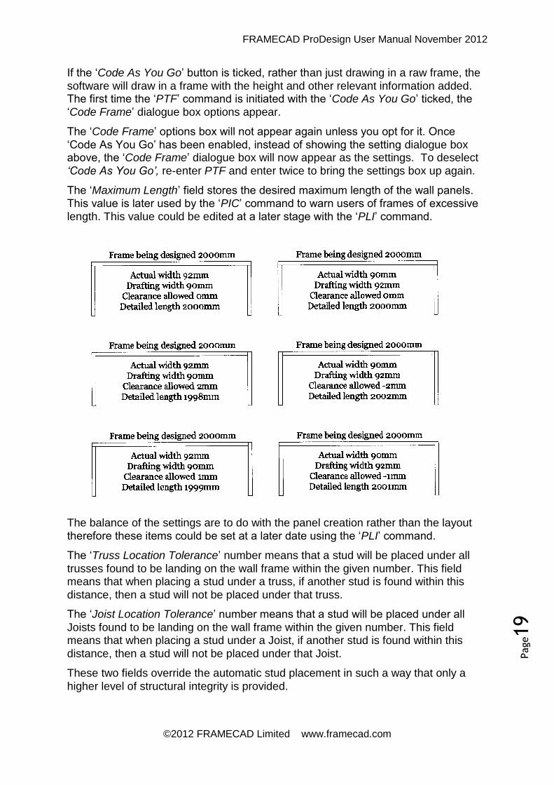
If the ‘Code As You Go’ button is ticked, rather than just drawing in a raw frame, the
software will draw in a frame with the height and other relevant information added. The first time the ‘PTF’ command is initiated with the ‘Code As You Go’ ticked, the
‘Code Frame’ dialogue box options appear.
The ‘Code Frame’ options box will not appear again unless you opt for it. Once
‘Code As You Go’ has been enabled, instead of showing the setting dialogue box above, the ‘Code Frame’ dialogue box will now appear as the settings. To deselect
‘Code As You Go’, re-enter PTF and enter twice to bring the settings box up again.
The ‘Maximum Length’ field stores the desired maximum length of the wall panels. This value is later used by the ‘PIC’ command to warn users of frames of excessive
length. This value could be edited at a later stage with the ‘PLI’ command.
The balance of the settings are to do with the panel creation rather than the layout therefore these items could be set at a later date using the ‘PLI’ command.
The ‘Truss Location Tolerance’ number means that a stud will be placed under all
trusses found to be landing on the wall frame within the given number. This field means that when placing a stud under a truss, if another stud is found within this
distance, then a stud will not be placed under that truss.
The ‘Joist Location Tolerance’ number means that a stud will be placed under all
Joists found to be landing on the wall frame within the given number. This field means that when placing a stud under a Joist, if another stud is found within this
distance, then a stud will not be placed under that Joist.
These two fields override the automatic stud placement in such a way that only a
higher level of structural integrity is provided.

FRAMECAD ProDesign User Manual November 2012
©2012 FRAMECAD Limited www.framecad.com
Page20
‘Use LB Clusters’ - If this option is ticked, then cluster studs will be placed at the wall frame intersections on load bearing wall frames. ‘Use ST Clusters’ - If this option is ticked, then plaster studs or cluster studs will be placed at the wall frame intersections on structural wall frames. ‘Use NLB Clusters’ - If this option is ticked, then plaster studs or cluster studs will be placed at the wall frame intersections on non load bearing wall frames. ‘Plaster Stud Increase’ is the distance by which the plaster studs will be increased. Normally the plaster studs will be spaced at the thickness of the wall frame. If the dimension is set to ‘5’ and the frame thickness was set to 75mm, then the gap between the end plaster studs would be 80mm. Alternately, if this dimension was a negative number, then the gaps would decrease.

FRAMECAD ProDesign User Manual November 2012
©2012 FRAMECAD Limited www.framecad.com
Page21
5.5 Panel Editing
With the layout drawings and panels detailed within the CAD environment, we use the entity type called a ‘Trace’. Whilst this serves our purpose well, it has a drawback
in the fact that most of the standard CAD editing tools cannot edit it. To overcome this deficiency we have created a range of commands similar to the standard CAD commands for this purpose. A description of their functionality is listed in the
proceeding section.
5.5.1 PE Panel Extend
This function will extend one member to meet another member. First select the member you wish to extend too, next select the member or members you wish to extend.
This command allows you to continue to select members to extend until the return key is pressed, right mouse button is pressed or no members are selected. This routine will work on all ‘trace’ entities only and retains all intelligence, layer and
colour properties.
5.5.2 PT Panel Trim
This command is used to trim off a member using another member as a cutting line. First select the member to be used as a cutting edge with the following members selected to be trimmed.
When selecting the members to trim, the side selected is the side that is kept. This is opposite to the standard CAD command. This command allows you to continue to select members to extend until the return key is pressed, right mouse button is

FRAMECAD ProDesign User Manual November 2012
©2012 FRAMECAD Limited www.framecad.com
Page22
pressed or no members are selected. This routine will work on all ‘trace’ entities only
and retains all intelligence, layer and colour properties.
5.5.3 IP Inherit Properties
This routine is used to copy the properties of one wall frame to another. This included layers, colours, line types and all extended data.
Very useful when you have coded the whole job and discovered that you have missed one frame. It saves having to remember what was done some time ago.
This routine will work on all ‘trace’ and ‘line’ type entities.
5.5.4 PF Panel Fillet
This command will fillet trace corners. To operate, select the two points close to the corners to be filleted. The first entity selected is the wall that will go the long
distance. This routine will work on all ‘trace’ entities.
5.5.5 PJ Panel Join
This function is used to join two adjoining members. To operate, select one member, then select the other member. If the two members are not adjoining or in
the same plane, then a new member will be drawn from the furthest points of the
members selected.
With this command, it does not matter which end of each member is selected as the new member will be drawn from the furthest points of the members selected. This
routine will work on all ‘trace’ entities.

FRAMECAD ProDesign User Manual November 2012
©2012 FRAMECAD Limited www.framecad.com
Page23
5.5.6 PC Panel Cut
This function cuts a wall panel at a given point. To operate first select the wall panel to cut, next select the point where you wish to cut the panel. When selecting the cutting point, the cursor snap mode has been set to select an end point or intersection. If needed you may wish to draw in a guideline to represent the cutting
point. This routine will work on all ‘trace’ entities.
5.5.7 PS Panel Square
5.5.8 PM Panel Mitre
This command will mitre trace corners. To operate, select the two points close to the corners to be mitres. This routine will work on all ‘trace’ entities.
5.5.9 PL Panel Lengthen
Enter a value to lengthen or shorten a wall by.

FRAMECAD ProDesign User Manual November 2012
©2012 FRAMECAD Limited www.framecad.com
Page24
5.5.10 PX Panel Crossing
5.6 Inputting Openings
5.6.1 UD User Defined Door Input
Use this command to input user defined doors. This will prompt the user for the door
trim height, trim opening width and location.
Refer section 5.15 on creating Opening Libraries.
5.6.1 UW User Defined Window Input
Use this command to input user defined windows. This will prompt the user for the window trim opening height, trim opening width and location. The finished head height for windows is set in the ‘Windows’ tab of the wall settings dialogue box (‘QSET’) or by selecting ‘S’ at the beginning of the ‘UW’ command.
Refer section 5.15 on creating Opening Libraries.
FRAMECAD ProDesign User Manual November 2012
©2012 FRAMECAD Limited www.framecad.com
Page25
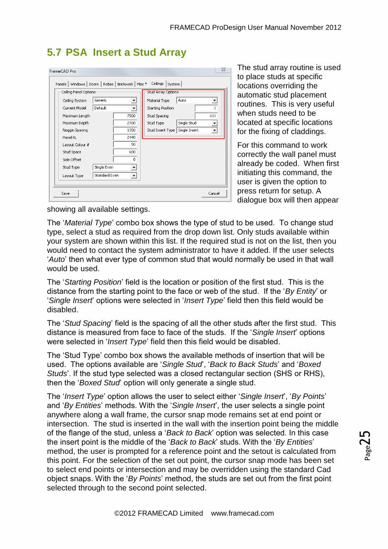
5.7 PSA Insert a Stud Array
The stud array routine is used to place studs at specific locations overriding the automatic stud placement routines. This is very useful when studs need to be located at specific locations for the fixing of claddings.
For this command to work correctly the wall panel must already be coded. When first initiating this command, the user is given the option to press return for setup. A dialogue box will then appear
showing all available settings.
The ‘Material Type’ combo box shows the type of stud to be used. To change stud
type, select a stud as required from the drop down list. Only studs available within your system are shown within this list. If the required stud is not on the list, then you would need to contact the system administrator to have it added. If the user selects ‘Auto’ then what ever type of common stud that would normally be used in that wall
would be used.
The ‘Starting Position’ field is the location or position of the first stud. This is the distance from the starting point to the face or web of the stud. If the ‘By Entity’ or ‘Single Insert’ options were selected in ‘Insert Type’ field then this field would be
disabled.
The ‘Stud Spacing’ field is the spacing of all the other studs after the first stud. This distance is measured from face to face of the studs. If the ‘Single Insert’ options
were selected in ‘Insert Type’ field then this field would be disabled.
The ‘Stud Type’ combo box shows the available methods of insertion that will be used. The options available are ‘Single Stud’, ‘Back to Back Studs’ and ‘Boxed Studs’. If the stud type selected was a closed rectangular section (SHS or RHS),
then the ‘Boxed Stud’ option will only generate a single stud.
The ‘Insert Type’ option allows the user to select either ‘Single Insert’, ‘By Points’ and ‘By Entities’ methods. With the ‘Single Insert’, the user selects a single point
anywhere along a wall frame, the cursor snap mode remains set at end point or intersection. The stud is inserted in the wall with the insertion point being the middle of the flange of the stud, unless a ‘Back to Back’ option was selected. In this case the insert point is the middle of the ‘Back to Back’ studs. With the ‘By Entities’
method, the user is prompted for a reference point and the setout is calculated from this point. For the selection of the set out point, the cursor snap mode has been set to select end points or intersection and may be overridden using the standard Cad object snaps. With the ‘By Points’ method, the studs are set out from the first point
selected through to the second point selected.

FRAMECAD ProDesign User Manual November 2012
©2012 FRAMECAD Limited www.framecad.com
Page26
These dialogue settings are stored in your systems register plus within ‘Layer Zero’
of the current drawing for future reference. When studs are inserted, the software will not insert studs at the ends of each wall panel or within a studs thickness of the starting and ending point of a window. The tolerance for this is 1.25 times the stud
width.
5.8 PIB Insert Bracing
This function allows the operator to insert bracing into the wall panel whilst they are in the layout stage. This command works with several different styles of bracing. The types of bracing available are K-Brace, Double Strap bracing and Single Strap
bracing.
When the command is first initiated, you are given the option to ‘Enter for Setup’, this
is where you can change the desired brace type. The setup will load a dialogue box showing all brace types available in your system, to change the bracing type simply select the option required from the dropdown combo box. If the brace type desired does not appear, you will need to confer with your systems administrator to see if it can be added. To exit the setup press either the ‘Save’ or ‘Cancel’ button as
required. These dialogue settings are stored in your systems register plus within ‘Layer Zero’ of the current drawing for future reference. For convenience, the
command prompt also shows the bracing style that is current.
The command works as a continuous command, in other words whilst you continue to pick points, it continues to insert bracing. To end the command either pick a point in the middle of nowhere, fail to pick a point, press the right mouse button or press the ‘Enter’ key on the keyboard.
To insert a brace select a point where you want the brace to start and the software will do the rest. The point selected should be a located somewhere between the studs, there is no need to be accurate as the software will find and calculate all other necessary items. The command only inserts a single brace with every point selected. If the bracing layer is not visible when the command is first initiated, then the software will make the layer visible. If no studs are found within the drawing, then the ‘PCW’ command will be initiated to update the drawing.
Your data file contains all the settings governing the minimum and maximum lengths. In all cases the software endeavours to insert a brace is such a way that the maximum strength is obtained. If the brace is less than the minimum length, then no brace will be drawn and a warning will be issued in the command prompt area.

FRAMECAD ProDesign User Manual November 2012
©2012 FRAMECAD Limited www.framecad.com
Page27
Where a brace is allowed to go over multiple stud bays, the brace will be drawn away from the closest end found. The closest end is defined as a wall panel end or an opening end. If there is an RHS or SHS post within a panel, then this is treated as another stud. If an existing brace is found within the last stud bay, then this brace
will be deleted and the new brace inserted.
On completion of each brace insertion, its racking resistance and overturning capacities are calculated and stored within the entity. Braces are inserted on a layer called ‘BRACE’ with single braces shown in the colour ‘50’ with double braces shown in the colour ‘100’. The entity type ‘TRACE’ is the only entity type used for drawing
braces.
‘Bracing’ can be manipulated with all the standard cad commands and trace editing commands. The ‘PLI’ command will allow you to view the bracing strengths and
capacities. If you wish to change the associated material type, this can be done by listing the associated panel and edit the material definitions there.
5.9 PLA Panel Labelling
To label the wall panels, use the ‘PLA’ command. This command gives the option of selecting the required panels or doing a global selection. If you select panels, a secondary dialogue box will ask you what number you wish to start the labelling at. The height of the labelling text is currently fixed at the same height as the dimensioning text. Labelling prefixes can be altered in the ‘Misc’ tab in ‘QSET’.
If you want to label your panels in a specific order, go into the ‘Misc’ tab in ‘QSET’ and tick on ‘Disable Sorting’, then select the panels in the required order within the PLA command.

FRAMECAD ProDesign User Manual November 2012
©2012 FRAMECAD Limited www.framecad.com
Page28
5.10 REF Reference Points
The software is basically a 2D program however with the ‘Reference Point’ system it has all the functionality of a 3D program. By inserting a ‘Reference Point’ on the wall layouts and corresponding ‘Reference Points’ on a truss layout or floor layouts, the
software will see this as an overlay, thus transferring loads automatically.
The first point inserted is called the primary point and subsequent points are called secondary points. The primary point is the point where the structure is built from. When the software needs to transfer loads, or build 3D views etc, the primary point is where they are build from and all entities associated with secondary points are
transferred to the primary point location.
For the ‘Reference Point’ system to work correctly there are four rules which must
apply:
1. The first rule is that there can only be one ‘Reference Point’ within a border.
2. The second rule is that there must be a minimum of two ‘Reference Points’ for
each reference number used.
3. The third rule is that there can only be one ‘Reference Point’ number for each
structure.
4. The final rule is that each ‘Reference Point’ must be placed in a
corresponding point within a border to the primary ‘Reference Point’.
The ‘PIC’ command will check and warn if any of the rules one to three are broken,
however the software cannot check the forth rule, so it is up to the user be aware
and be careful.
When the first ‘Reference Point’ is inserted into the drawing, it is automatically a primary point and will be given an ID of one. All subsequent points inserted will be secondary points given the same ID number. The ID number will not change until such time as a new primary ‘Reference Point’ is inserted. To insert a new primary point, press ‘P’ before inserting the ‘Reference Point’. The ID number will be
automatically incremented. There is no way to add a specific ID number however, the ID number can be edited through the ‘PLI’ command.
When a ‘Reference Point’ is inserted, it is placed on the layer ‘Defpoints’. This is a special layer that does not print therefore ‘Reference Points’ are only visible to the operator. The primary ‘Reference Point’ is shown in a bright green colour and
secondary reference points are shown in a dull green colour.

FRAMECAD ProDesign User Manual November 2012
©2012 FRAMECAD Limited www.framecad.com
Page29
5.11 PIC Panel Integrity Check
This command is used to check for drafting errors and simple mistakes made by the detailer. It checks for eleven major errors and issues two types of warnings. It should be stressed that this command could not be used enough. It should be used several times on EVERY job. Whilst it should not be relied upon, this command could be your best friend, and save much embarrassment by attempting to eliminate errors.
The eleven major errors detected are listed below:
1. Integrity of reference points (critical warning)
2. Wall panels that are not coded (cyan) (warning only)
3. Wall panels that are not labeled (yellow) (warning only)
4. Wall panels that are short (blue) (warning only)
5. Wall panels that are overlapping (yellow) (warning only)
6. Wall panels exceeding maximum length (magenta) (warning only)
7. Wall panels exceeding transport limitations (magenta) (warning only)
8. Openings spread over two wall panels (brown) (warning only)
9. Braces spread over two wall panels (brown) (warning only)
10. Entities of very small lengths (red) (critical warning)
11. Entities with a ‘Z’ coordinate value (red) (critical warning)
12. Engineering failures (red++) (warning only)
The two types of warnings issued are ‘Critical Warnings’ and ‘Warning Only’. Should
you receive a ‘Critical Warning’ then this MUST be fixed before proceeding any further, but a ‘Warning Only’ is purely up to your own discretion. Whilst ever a ‘Critical Warning’ is being generated or present, the ‘PPD Panel Builder’ command will not operate. Once a ‘Critical Error’ has been detected, the only way to clear the error is to fix the problem and run the ‘PIC’ command until the ‘Critical Error’ warning
does not appear.
Of the eleven warnings, only the first nine are optional and can be accessed via the settings option. We do recommend that options 1 (Reference Points), 4 (Panel

FRAMECAD ProDesign User Manual November 2012
©2012 FRAMECAD Limited www.framecad.com
Page30
Length Shortage) and 5 (Panel Overlaps) remain on at all times as these are a major
cause of drafting errors.
When the command is first initiated, the user is given the option to press ‘S’ for setup or ‘Enter’ to continue. If you press ‘S’ then this will take you into the setting options. The ‘PIC’ settings are saved globally and are not saved within each drawing. If you opt for ‘Enter’, then all wall panels in the current view only will be checked. It is important to remember that the ‘PIC’ command will only check items found in the
current view.
When an error is found, the location is marked with an asterisk and a warning box appears showing the errors found. An example of the warning box is shown to the left. The asterisk is colour coded making it easy to identify the error at that point. The
colours used are listed above beside each error type.
5.12 PLI List Frame
The ‘PLI’ function is basically the command centre for the wall frame software. It is a
truly multi functional command. Its function varies with the type of entity selected, and where no entity is selected it shows the available commands for that section. If you want to perform a task and don’t know what to do, then ‘PLI’ should be able to help you. Below the functionality of each of its operations are described in much more detail. This command allows the user to select one or multiple entities; the first entity selected is the type of entity that will be displayed.
5.12.1 Coding a Frame/Beam
If you select an entity that has been created with the ‘PFT Trace Frame’ function and
that item has not yet received its intelligence then this option will be initiated. This is where you give the wall or beam its intelligence. When the command is first initiated a dialogue box appears. This box has two tabs on the top; one is for coding as a wall frame ‘Code Frame’ and the other is for coding as a beam ‘Code Beam’.
FRAMECAD ProDesign User Manual November 2012
©2012 FRAMECAD Limited www.framecad.com
Page31
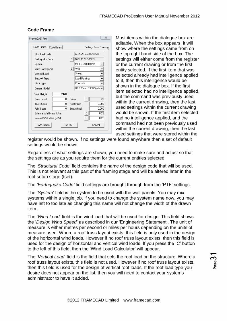
Code Frame
Most items within the dialogue box are editable. When the box appears, it will show where the settings came from on the top right hand side of the box. The settings will either come from the register or the current drawing or from the first entity selected. If the first item that was selected already had intelligence applied to it, then this intelligence would be shown in the dialogue box. If the first item selected had no intelligence applied, but the command was previously used within the current drawing, then the last used settings within the current drawing would be shown. If the first item selected had no intelligence applied, and the command had not been previously used within the current drawing, then the last used settings that were stored within the
register would be shown. If no settings were found anywhere then a set of default settings would be shown.
Regardless of what settings are shown, you need to make sure and adjust so that
the settings are as you require them for the current entities selected.
The ‘Structural Code’ field contains the name of the design code that will be used.
This is not relevant at this part of the framing stage and will be altered later in the roof setup stage (tset).
The ‘Earthquake Code’ field settings are brought through from the ‘PTF’ settings.
The ‘System’ field is the system to be used with the wall panels. You may mix
systems within a single job. If you need to change the system name now, you may
have left to too late as changing this name will not change the width of the drawn item.
The ‘Wind Load’ field is the wind load that will be used for design. This field shows the ‘Design Wind Speed’ as described in our ‘Engineering Statement’. The unit of
measure is either metres per second or miles per hours depending on the units of measure used. Where a roof truss layout exists, this field is only used in the design of the horizontal wind loads. However if no roof truss layout exists, then this field is used for the design of horizontal and vertical wind loads. If you press the ‘C’ button
to the left of this field, then the ‘Wind Load Calculator’ will appear.
The ‘Vertical Load’ field is the field that sets the roof load on the structure. Where a
roof truss layout exists, this field is not used. However if no roof truss layout exists, then this field is used for the design of vertical roof loads. If the roof load type you desire does not appear on the list, then you will need to contact your systems
administrator to have it added.

FRAMECAD ProDesign User Manual November 2012
©2012 FRAMECAD Limited www.framecad.com
Page32
The ‘Support Type’ field sets what type of wall frame it is. There are three choices here, ‘Load Bearing’, ‘Non Load Bearing’ and ‘Structural’. A ‘Load Bearing’ wall means that the wall will be designed for vertical and horizontal loads. These loads can be either evenly distributed or point loaded. A ‘Non Load Bearing’ wall means
that the wall will not be designed for vertical or horizontal loads (with some exceptions). A ‘Structural’ wall means that the wall will be designed for vertical and
horizontal loads but presumes that the wall is not point loaded in any way. If you have any sort of doubts as to what sort of wall to use, then make it a ‘Load Bearing’
wall.
The ‘Floor Type’ field shows what type of floor the wall is fixed to. There are currently
three choices, ‘Concrete’, ‘Steel’ and ‘Timber’. This field is used to calculate bills of
materials or the strength of hold down fasteners.
The ‘Current Model’ is the sub system to be used with the selected entities. You may mix systems and sub systems within a single job. To find out specifically what the sub system is, you will need to talk with your systems administrator. If you need to change the current model now, you may have left to too late as changing this name will not change the width of the drawn item.
The ‘Wall Height’ sets the height at which the wall frames will be detailed. This is the
height from the base to the top of the top plate, assuming that the wall is not raked.
The ‘Base RL’ field is the base RL of the wall panel in the 3D world environment. It is
vital that this field be correct as the software uses the levels to create 3D models for the purpose of load transfers. The ‘P3D’ command will show you quickly whether you
are right or wrong.
The ‘Truss Span’ and ‘Pitch’ only needs to be correct if you have a roof truss layout in the current drawing. If the truss layout drawing is ‘Referenced’ to the wall frames,
the truss information is updated from the trusses found and these fields are not used.
The ‘Floor Span’ only needs to be used if you have a floor load landing on the walls
and will not have a detailed floor system referenced in the current drawing. If there is
no floor load involved, then this value should be zero.
The ‘Colour’ field allows you to set the colour for the walls being coded. This is useful when differentiating different wall types. To use standard wall colours, leave this field set to ‘Bylayer’. By default ‘Load Bearing’ walls are drawn in colour ‘20’ with ‘Structural’ walls drawn in colour ‘212’ and ‘Non Load Bearing’ walls drawn in colour ‘60’.
The ‘Snow’ field allows you to set the vertical snow loads. If the truss layout drawing is ‘Referenced’ to the wall frames the truss information is transferred from the
trusses and this field is in addition to the snow load inherited from the trusses. So if no additional snow loads are required, this field should be left at zero. The unit of
measure is either kPa or psf depending on the units of measure used.
The ‘Wall Mass’ fields show the weight of the cladding that is attached to the wall. At
this stage the software does not know whether the walls are external of internal, so both are shown. Generally they are set on a job basis, so therefore there is no need to change them regularly. The unit of measure is either kPa or psf depending on the
units of measure used.

FRAMECAD ProDesign User Manual November 2012
©2012 FRAMECAD Limited www.framecad.com
Page33
The ‘Run FSET’ button is only of use when you are tracing frames with ‘Code As You Go’ enabled. This button is needed to get back to the main settings to turn off ‘Code As You Go’.
Code Beam
When coding beams use caution as if the beam width varies from the drawn width, the software will adjust the width. It is up to the user to ensure that the correct size has been adjusted. If the beam width was adjusted, the software will issue a warning so the user is aware of it. Please make sure you check all intersection and
corner points when this happens.
Regardless of what settings are shown, you need to make sure and adjust so that the settings are as you require them for
the current entities selected.
The ‘System Name’ field is the name of the system file that contains the beam definitions. You may mix systems within a
single job. If you need to change the system name now, you may have left to too late as changing this name will not change the width of the drawn item.
The ‘Beam Name’ field is the name of the beam you wish to use. If the beam you wish to use does not appear on the list, you could use the ‘Add Beam’ button to add
the required beam. Not only can you add a beam here, but you can also edit or delete existing beams. To exit or delete an existing beam, click or double click the
desired beam and its properties will fill the appropriate fields.
The ‘Beam Clearance’ will shorten the beam by this length. E.g. if a beam was
6000mm long and the clearance was set at 5mm, then the final length detailed would be 5995mm. A point to remember is that this clearance is not shown in the layout -
the beam still remains drawn at the full length.
The ‘Beam Top RL’ sets the top level or vertical location of the beam. It is essential to have this correct as it is used for load calculations and by the ‘Beam Lapping’
function.
The ‘Beam Note’ field allows you to add notes to the beam that will appear on the
detailed beams.
5.12.2 Listing an Opening
If the first item selected after PLI had been an opening then the following dialogue box would have appeared. This box shows most of the properties associated with openings.
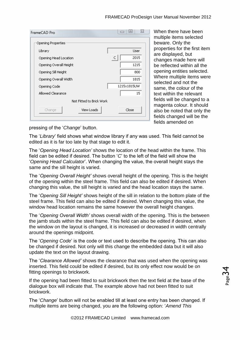
FRAMECAD ProDesign User Manual November 2012
©2012 FRAMECAD Limited www.framecad.com
Page34
When there have been multiple items selected beware. Only the properties for the first item are displayed, but changes made here will be reflected within all the opening entities selected. Where multiple items were selected and not the same, the colour of the text within the relevant fields will be changed to a magenta colour. It should also be noted that only the fields changed will be the fields amended on
pressing of the ‘Change’ button.
The ‘Library’ field shows what window library if any was used. This field cannot be
edited as it is far too late by that stage to edit it.
The ‘Opening Head Location’ shows the location of the head within the frame. This field can be edited if desired. The button ‘C’ to the left of the field will show the ‘Opening Head Calculator’. When changing the value, the overall height stays the
same and the sill height is varied.
The ‘Opening Overall Height’ shows overall height of the opening. This is the height
of the opening within the steel frame. This field can also be edited if desired. When changing this value, the sill height is varied and the head location stays the same.
The ‘Opening Sill Height’ shows height of the sill in relation to the bottom plate of the
steel frame. This field can also be edited if desired. When changing this value, the
window head location remains the same however the overall height changes.
The ‘Opening Overall Width’ shows overall width of the opening. This is the between the jamb studs within the steel frame. This field can also be edited if desired, when the window on the layout is changed, it is increased or decreased in width centrally
around the openings midpoint.
The ‘Opening Code’ is the code or text used to describe the opening. This can also be changed if desired. Not only will this change the embedded data but it will also
update the text on the layout drawing.
The ‘Clearance Allowed’ shows the clearance that was used when the opening was
inserted. This field could be edited if desired, but its only effect now would be on fitting openings to brickwork.
If the opening had been fitted to suit brickwork then the text field at the base of the dialogue box will indicate that. The example above had not been fitted to suit
brickwork.
The ‘Change’ button will not be enabled till at least one entry has been changed. If multiple items are being changed, you are the following option: ‘Amend This

FRAMECAD ProDesign User Manual November 2012
©2012 FRAMECAD Limited www.framecad.com
Page35
Opening...Y for Yes, N for No or A for All...’. If you press ‘Y’ then that item will be amended, if you press ‘N’ then that item will not be amended and if you press ‘A’
then all selected items will be amended. Make your decision wisely.
5.12.3 Listing a Brace Panel
If the first item selected was a brace, then the dialogue box below would appear. Where multiple items were selected and not the same, the colour of the text within the relevant fields will be changed to a magenta colour. The only item editable is this dialogue box is the ‘Brace Quantity’, and then this is only possible if it is a strap
brace that has been listed.
The ‘Brace Type’ shows the exact
type of bracing, it could be either a strap brace, or a K-brace or a X-brace or a type A or B sheet brace as defined in the ‘Australian Timber Framing Code’.
The ‘Brace Length’ field shows the
overall plan length of the brace.
The ‘X Contribution’ in the total value of ‘Racking’ or ‘Overturning’ resistance offered in the ‘X
Direction’ only.
The ‘Y Contribution’ in the total
value of ‘Racking’ or ‘Overturning’ resistance offered in the ‘Y Direction’ only.
The ‘Brace Quantity’ refers to strap bracing only and has two possible values of
either single or double quantity.
The ‘Change’ button will not be enabled till at least one entry has been changed. The only item currently editable is the ‘Brace Quantity’ field and this is only enabled on
‘Strap Brace’ types.
If multiple items are being changed, you are the following option: ‘Amend This Opening...Y for Yes, N for No or A for All...’. If you press ‘Y’ then that item will be amended, if you press ‘N’ then that item will not be amended and if you press ‘A’
then all selected items will be amended. Make your decision wisely.
5.12.4 Listing a 3D Entity
On listing a 3D wall entity, the listing box for the associated 2D entity will be shown. From here you can edit the entities properties as desired. However the 3D entity will not change. If you want to see changes in the 3D entity, you will need to build the 3D
entities again.

FRAMECAD ProDesign User Manual November 2012
©2012 FRAMECAD Limited www.framecad.com
Page36
5.12.5 Listing a Beam
Almost everything within the ‘List a Beam’ dialogue is editable, and almost
everything can be changed. This dialogue box also serves as the command centre for beam related commands.
The ‘System’
field displays the name of the system from where these particular beams properties were acquired from. Changing this field now will not affect the current beam in any way, however it could change the available beams listed in the ‘Beam Type’
field.
The ‘Beam Type’ field displays the name of the current beam. By dropping down this
combo box, a list of all available beams within the current system will be shown and can be selected as desired. On changing the beam type the ‘Beam Profile’, ‘Beam
Height’, ‘Beam Width’ and ‘Beam Weight’ fields will be automatically updated.
The ‘Beam Profile’ field is not editable or changeable and merely shows the shape of
profile of the current selected field.
The ‘Beam Top RL’ field shows the location of the beam relative to the 3D axis. The location shown is to the top of the beam. It is important that this location be correct as its information needs to be correct for the ‘Beam Lap’ functions to operate
correctly as well as the 3D viewing.
The ‘Beam Clearance’ field is the overall clearance or length that will be deducted from the overall beams length when it is detailed or within any reports. This ‘Clearance’ has been preset within your data file, but can be edited if desired.
The ‘Beam Note’ is a note this is included on any detail sheets where the beam is detailed. This is similar to the ‘Red Line Text’ field immediately below. The only difference is that the ‘Beam Note’ is stored within your data file and appears every time that beam is used, where as the ‘Red Line Text’ is added by the user on a job
by job basis.
The ‘Beam Colour’ is the colour that the beam will be shown on the layout. This
colour is initially stored within your data file but you can change it as desired.

FRAMECAD ProDesign User Manual November 2012
©2012 FRAMECAD Limited www.framecad.com
Page37
The ‘Beam Label’ fields shows the label that was given when the ’PLA’ command
was used. Only the prefix portion of this is editable. Under normal circumstances this should never need to be changed, however if you want to you can.
The ‘Beam Height’ field shows the actual height of the beam. This height has come
from the beam data stored within your data file, so normally you should not need to change it. However if you do change if be aware of the other downstream items you could effect, such as 3D views and beam laps.
The ‘Beam Width’ field shows the actual width of the beam as detailed. This width
has come from the beam data stored within your data file, so normally you should not need to change it. However, if you do change the width, the beam shown on the layout will change. You would be well advised to check all intersections and corners
as quite often these will need to be adjusted or cleaned up.
The ‘LH Beam Lap’ and ‘RH Beam Lap’ shows the distance (if any) that the beam is lapped into the frame. The length of the beam on the layout does not change,
however the detailed length and reported length will be adjusted by these amounts. If you change a lap back to zero, then the marker circles on the layout will be removed. Likewise when you change a lap from zero to a positive number the marker
circles will be added.
The ‘Raw Length’ field shows the length of the beam as drawn on the layout. The ‘Finished Length’
shows the length of the beam as detailed or reported.
The ‘Change’ button will not be
enabled till at least one entry has
been changed. If multiple items are being changed, you are the following option: ‘Amend This Opening...Y for Yes, N
for No or A for All...’. If you press ‘Y’ then that item will be amended, if you press ‘N’ then that item will not be amended and if you press ‘A’ then all selected items will be
amended. Make your decision wisely.
You should also note that only the fields that were changed are the fields that will be amended or updated. So if you don’t edit a particular field, then this field will not be changed. This is very useful when you have selected multiple entities that are not all the same and only want to change one particular field. This basically applied to all of
the dialogue boxes listings.
5.12.6 Listing a Reference Point
There is very little to edit of a ‘Reference Point’ however if required, you can change
the point type and its ‘Reference Index’.

FRAMECAD ProDesign User Manual November 2012
©2012 FRAMECAD Limited www.framecad.com
Page38
The ‘Change’ button will not be enabled
until at least one item has been changed. If you change a ‘Reference Point’ from a
primary of secondary, you will see the item change colour. The ‘Primary’ points are shown in a bright green whereas a ‘Secondary’ point is shown in a dull green.
On changing anything within this dialogue, the ‘PIC’ command will check integrity of ‘Reference Points’ on completion.
5.13 Dimensioning
5.13.1 DH Dimension Horizontally
This routine will dimension horizontally from point to point. Select the dimension location then select the points you wish to dimension. When selecting points to dimension, the cursor has been set to pick end points or intersections. This routine
will only dimension using the ‘X’ coordinates.
5.13.2 DV Dimension Vertically
This routine will dimension vertically from point to point. Select the dimension location then select the points you wish to dimension. When selecting points to dimension, the cursor has been set to pick end points or intersections. This routine
will only dimension using the ‘Y’ coordinates.
5.13.3 DA Dimension Aligned
This routine will dimension wall between two points. Select the dimension location then select the points you wish to dimension. When selecting points to dimension, the cursor has been set to pick end points or intersections. This routine will
dimension at whatever angle the second point is from the first.
5.13.4 DOH Dimension Ordinates Horizontally
This routine will produce a series of running ordinate dimensions from a given reference point. This routine will only dimension using the ‘X’ coordinates. To use this function first select the location where you want the dimensions to appear, then continue selecting point to dimension. The first point selected will be considered to
be ‘0’, the rest of the points will be set from this point.
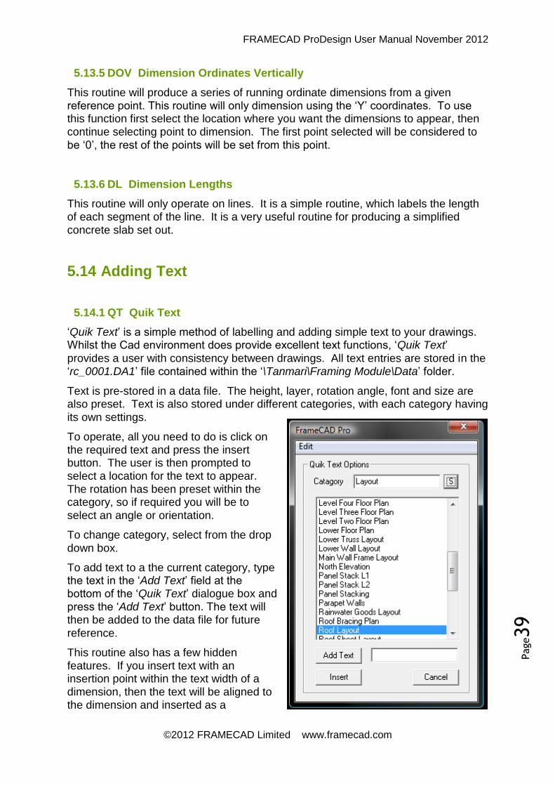
FRAMECAD ProDesign User Manual November 2012
©2012 FRAMECAD Limited www.framecad.com
Page39
5.13.5 DOV Dimension Ordinates Vertically
This routine will produce a series of running ordinate dimensions from a given reference point. This routine will only dimension using the ‘Y’ coordinates. To use this function first select the location where you want the dimensions to appear, then continue selecting point to dimension. The first point selected will be considered to
be ‘0’, the rest of the points will be set from this point.
5.13.6 DL Dimension Lengths
This routine will only operate on lines. It is a simple routine, which labels the length of each segment of the line. It is a very useful routine for producing a simplified
concrete slab set out.
5.14 Adding Text
5.14.1 QT Quik Text
‘Quik Text’ is a simple method of labelling and adding simple text to your drawings. Whilst the Cad environment does provide excellent text functions, ‘Quik Text’
provides a user with consistency between drawings. All text entries are stored in the ‘rc_0001.DA1’ file contained within the ‘\Tanmari\Framing Module\Data’ folder.
Text is pre-stored in a data file. The height, layer, rotation angle, font and size are also preset. Text is also stored under different categories, with each category having
its own settings.
To operate, all you need to do is click on the required text and press the insert button. The user is then prompted to select a location for the text to appear. The rotation has been preset within the category, so if required you will be to
select an angle or orientation.
To change category, select from the drop
down box.
To add text to a the current category, type the text in the ‘Add Text’ field at the bottom of the ‘Quik Text’ dialogue box and press the ‘Add Text’ button. The text will then be added to the data file for future
reference.
This routine also has a few hidden features. If you insert text with an insertion point within the text width of a dimension, then the text will be aligned to the dimension and inserted as a

FRAMECAD ProDesign User Manual November 2012
©2012 FRAMECAD Limited www.framecad.com
Page40
dimension post text. If you insert text with an insertion point within the text width of a border, then the text will be aligned to the bottom of the border at a preset height above the borders title line.
At the top of the dialogue box, there is an additional dropdown menu labelled ‘Edit’. This menu gives you several editing options to add, amend or delete categories plus
the ability to delete a text entry.
5.14.2 Add/Edit Categories
With this function, you can add, edit or delete a category. If deleting a category, be absolutely sure what you are doing as that category and all other entries under that
category will be deleted.
To edit a category, double click on the text in the right hand list box. Information will then be transferred to the left hand details. Amend as desired then press the ‘Add/Update’ button.
Double click on the text in the right hand list box. Information will then be transferred to the left hand details, then press the ‘Delete’ button. The category and all its
entries will then be removed.

FRAMECAD ProDesign User Manual November 2012
©2012 FRAMECAD Limited www.framecad.com
Page41
5.15 Opening Libraries
FRAMECAD ProDesign Software has the capacity of storing unlimited opening libraries. These opening library files are stored in the ‘C:\Program Files\Tanmari\Framing Module\Library’ folder with all data in a simply text format. The files have an extension type of ‘da2’. All users have access to the these files and by following the notes below you may edit, amend or create new library files as
desired.
5.15.1 The Basic Format
The file structure is broken into eight main sections and sub sections. The main
sections are listed in the table below:
Code Use Opening Type
H_AW Heights Aluminium windows
W_AW Widths Aluminium windows
H_AD Heights Aluminium doors
W_AD Widths Aluminium doors
H_TW Heights Timber windows
W_TW Widths Timber windows
H_TD Heights Timber doors
W_TD Widths Timber doors
The sub sections relate to the main sections and any information must be located below the main section marker and before the next main section marker. The sub sections are made up of single lines of data containing the code and the required
size with the ‘=’ symbol in between. Below is an extract from a library:
H_AW 10=1029 12=1200 14=1372
W_AW 06=610 09=850 12=1210
So when a user inserts an aluminium window with a code of ‘1012’, the software reads the heights for the opening from the information under the ‘H_AW’ section, it finds the ‘10’ line and therefore sets the height distance to 1029mm. For the widths the software looks for the ‘W_AW’ section, it finds the ‘12’ line and therefore sets the height distance to 1210mm.

FRAMECAD ProDesign User Manual November 2012
©2012 FRAMECAD Limited www.framecad.com
Page42
5.15.2 To Edit a File
To edit, change or amend an existing file please follow the procedure below:
Start Windows Explorer
Change to the ‘C:\Program Files\Tanmari\Framing Module\Library’
Double click on the file you wish to edit
It is recommended that you open this file with ‘Notepad’ or any other similar text editor. If the file extensions are not visible then it is recommended that you turn them on. If you do not know how to do this, then please go to the help pages on our website and download the relevant document. This link will take you to that document: http://www.rcassoc.com.au/Show File Types.pdf
Once the file is opened, you may insert additional lines or delete, alter or change
existing lines.
DO NOT delete or remove the section markers. All eight main section masters must be present and should, under no circumstances, be removed. When editing sub sections, the window code is restricted to two characters and must be followed by the equals (=) symbol and a length. There must be no spaces within the line.
5.15.3 To Create a File
The easiest way to create a new opening library file is to copy an existing file and edit it. To copy existing files please follow the procedure below:
Start Windows Explorer
Change to the ‘\Tanmari\Framing Module\Library’
Single click on the file you wish to edit
Press Ctrl C to copy the file
Press Ctrl V to paste the new file
Right click on the new file and select rename
Rename the file as required but make sure you do not change the file extension
Follow the procedure above to edit the file as required Also note the opening library file names should be limited to eight (8) characters and this file name should not contain spaces or punctuation characters. If the file extensions are not visible, then it is recommended that you turn them on. If you do not know how to do this, then please go to the help pages on our website and download the relevant document. This link will take you to that document: http://www.rcassoc.com.au/Show File Types.pdf

FRAMECAD ProDesign User Manual November 2012
©2012 FRAMECAD Limited www.framecad.com
Page43
Dialogue Styles
Most of the ‘FRAMECAD Pro’ dialogue boxes use a smart colour system. When the software changes a value automatically, the colour of the text usually changes to ‘RED’. When the user changes a value, the colour of the text usually changes to
‘BLUE’.
6.1 Roof Block Theory
6.1.1 Basis of Operation
The software operates as an add-on to the IntelliCAD cad package, thus providing a very powerful all in one drawing, detailing and engineering package.
The truss package operates basically as a 2D detailing package with its own built in structural design engine. Whilst it does have 3D viewing capacities, it is primarily a 2D package.
The truss package has two distinct parts, the first part is the roof truss layout and the second part is the actual truss building. These two parts are linked via a text base output file generated from the truss layout.
To detail the roof trusses, you first need to draw in the roof plan. This is usually the hardest part of the detailing process. Once this has been done, usually the creation of the roof truss layout is relatively simple. Generation of the trusses is a fully automated process, but should it be required, they may be edited using standard cad commands or our custom routines.
6 Truss Layouts

FRAMECAD ProDesign User Manual November 2012
©2012 FRAMECAD Limited www.framecad.com
Page44
6.1.2 Roof Theory
The truss software operates on the basis that every roof is a rectangle or a collection of rectangles. Throughout this training manual these rectangles will be referred to as roof blocks.
Sometimes these roof blocks may merge or overlap, and sometimes they may have more than four sides, but broadly speaking they are still a collection of blocks.
The trick to creating accurate roof plans and truss layouts is to be able to identify the roof blocks. When identifying roof blocks, it is usually easier to start with the smallest blocks and work up to the largest block. Using this method you can usually simplify the drawing as you go.
The drawing below shows an example of a roof consisting of two roof blocks.
Where the entire roof is of one pitch, all roof lines will be at right angle to each other, with the hips and valleys at 45 degree angles.
Regardless of the complexity of the roof, the direction of fall is ALWAYS towards a gutter or valley. If ever you have a roof falling to a hip or ridge, you have a problem as water will not run up hill.

FRAMECAD ProDesign User Manual November 2012
©2012 FRAMECAD Limited www.framecad.com
Page45
This example is a more complex roof consisting of four roof blocks.

FRAMECAD ProDesign User Manual November 2012
©2012 FRAMECAD Limited www.framecad.com
Page46
The example below shows a good example of a complex roof. Note the overlap of the two roof blocks. Generally when you have an overlap of roof blocks, you have a complex roof. The larger the overlap, the more complex the roof.
Note the direction of fall. On each occasion the roof MUST fall to a valley or gutter.
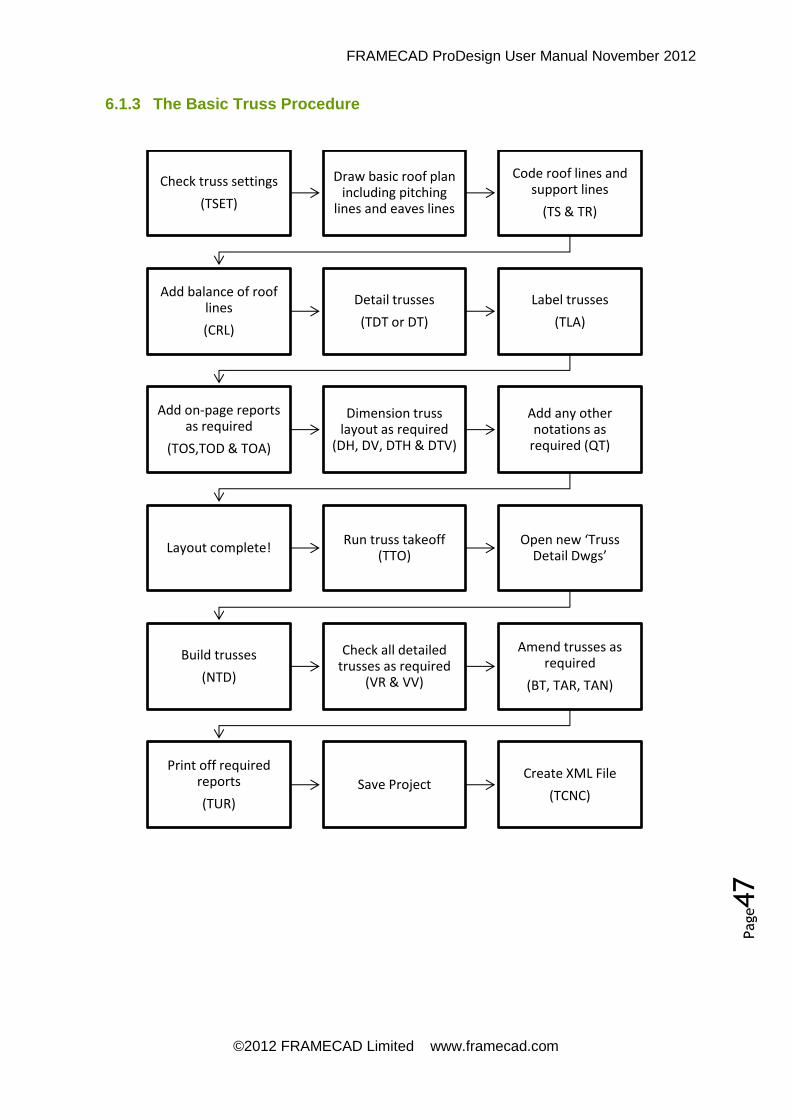
FRAMECAD ProDesign User Manual November 2012
©2012 FRAMECAD Limited www.framecad.com
Page47
6.1.3 The Basic Truss Procedure
Check truss settings
(TSET)
Draw basic roof plan including pitching
lines and eaves lines
Code roof lines and support lines
(TS & TR)
Add balance of roof lines
(CRL)
Detail trusses
(TDT or DT)
Label trusses
(TLA)
Add on-page reports as required
(TOS,TOD & TOA)
Dimension truss layout as required
(DH, DV, DTH & DTV)
Add any other notations as
required (QT)
Layout complete! Run truss takeoff
(TTO) Open new ‘Truss
Detail Dwgs’
Build trusses
(NTD)
Check all detailed trusses as required
(VR & VV)
Amend trusses as required
(BT, TAR, TAN)
Print off required reports
(TUR)
Save Project Create XML File
(TCNC)

FRAMECAD ProDesign User Manual November 2012
©2012 FRAMECAD Limited www.framecad.com
Page48
6.2 The Basic Settings
6.2.1 Border Setups
Refer Section 5.2
6.2.2 TSET Truss Setup Options
All of the main truss settings are contained in one dialogue box. This dialogue box is accessed from the ‘TSET’ command. When ‘TSET’ is initiated within an existing truss layout drawing, it will show all of the last used settings within that drawing. When initiating ‘TSET’ on a new drawing, it will only show the last settings used.
To change the truss system, select the appropriate option from the drop down box next to ‘System Name’. After selecting a truss system, all truss settings will be restored to the selected system defaults, however the truss pitch and the wind load will remain unchanged.
Each roof type has its own set of loadings. The types of roofing that are available have been preset within your systems data file. To change the roof type, click on the drop down box to the right of the ‘Roof Load’ field. When a new roof type is selected, the current settings are retrieved from the current drawing. If there are no load settings in the current drawing, then the settings

FRAMECAD ProDesign User Manual November 2012
©2012 FRAMECAD Limited www.framecad.com
Page49
are retrieved from the ‘INI’ file. If there are no settings found, then default settings are restored and the operator is warned of this. Roof loads can be altered in the loadings tab.
To select the required wind and roof load click on the drop down box to the left of the field. All available options have been preset within the data file, therefore only these options can be used. On selecting a wind load all truss settings associated with that load will be restored to the selected system defaults with the truss pitch and the wind load will remain unchanged.
The ‘Roof pitch’ field is the nominal pitch of the roof. In the case of dual pitch roofs, it is the pitch used for the main body. In the case of multiple roof pitches, it is only the default or starting point for the roof pitch. There is no need to enter hip pitches or other associated pitches as the software will look after these values.
Clicking on the ‘#’ to the right of this label brings up a simple roof pitch calculator which can convert the rise over run to a decimal roof pitch. Click on the ‘Transfer’ button to transfer the new calculated pitch back to the main dialogue box.
The ‘Sub Pitch’ or secondary pitch option is used for bell trusses or multi-pitched roofs.
The ‘Roof RL’ field sets the relative RL to the roof truss layout. Its only purpose is for viewing of trusses in 3D. This is used by some operators to do visual checks on more complex type roof structures.
The ‘Hip Method’ field sets the type of hip end to be used. Currently there are two options, Truss Style and Rafter Style. It will depend on your preference as to which method you will use.
The ‘O/H Method’ sets the method required to achieve the gable overhangs. All options are hard codes, to make sure your truss system is capable of using the method employed. The gable frame option currently has no effect on the drawings; it is used only as an indicative setting only.
The ‘Pitch Type’ option enables single or dual pitch mode. In this mode the ends of the roof block may have different pitches to the main body of the block, allowing a maximum of three pitches per block.
The ‘Detailing Type’ option allows you to change between ‘Full Truss’, ‘Half Truss’ or ‘Rafter’ roofs.
The ‘Truss Spacing’ field is the spacing of the standard trusses. Click on the ‘Truss Spacing’ wording to change between equal (or nominal) (E), and actual (A). If the spacing was set to equal (E) then this setting would be the maximum spacing of the standard trusses. If the spacing was set to actual (A) then this setting would be the precise spacing between standard trusses. Defined as ‘Dimension A’ in the definition drawing below.
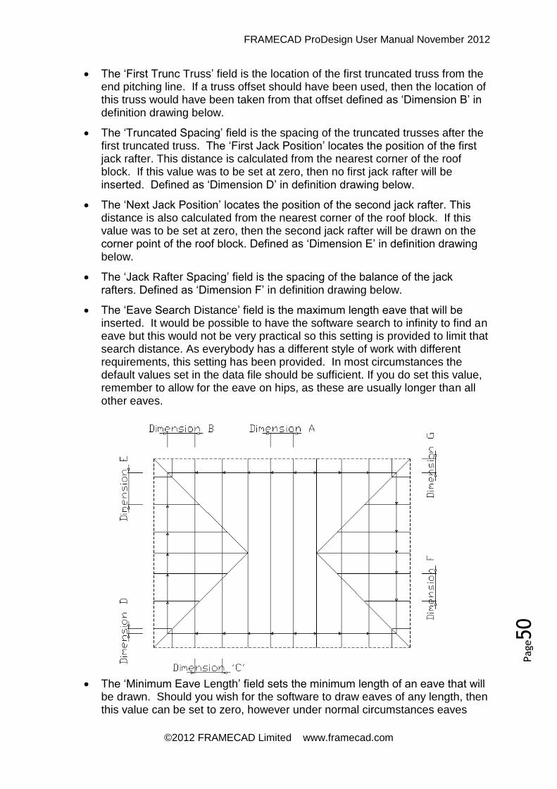
FRAMECAD ProDesign User Manual November 2012
©2012 FRAMECAD Limited www.framecad.com
Page50
The ‘First Trunc Truss’ field is the location of the first truncated truss from the end pitching line. If a truss offset should have been used, then the location of this truss would have been taken from that offset defined as ‘Dimension B’ in definition drawing below.
The ‘Truncated Spacing’ field is the spacing of the truncated trusses after the first truncated truss. The ‘First Jack Position’ locates the position of the first jack rafter. This distance is calculated from the nearest corner of the roof block. If this value was to be set at zero, then no first jack rafter will be inserted. Defined as ‘Dimension D’ in definition drawing below.
The ‘Next Jack Position’ locates the position of the second jack rafter. This distance is also calculated from the nearest corner of the roof block. If this value was to be set at zero, then the second jack rafter will be drawn on the corner point of the roof block. Defined as ‘Dimension E’ in definition drawing below.
The ‘Jack Rafter Spacing’ field is the spacing of the balance of the jack rafters. Defined as ‘Dimension F’ in definition drawing below.
The ‘Eave Search Distance’ field is the maximum length eave that will be inserted. It would be possible to have the software search to infinity to find an eave but this would not be very practical so this setting is provided to limit that search distance. As everybody has a different style of work with different requirements, this setting has been provided. In most circumstances the default values set in the data file should be sufficient. If you do set this value, remember to allow for the eave on hips, as these are usually longer than all other eaves.
The ‘Minimum Eave Length’ field sets the minimum length of an eave that will be drawn. Should you wish for the software to draw eaves of any length, then this value can be set to zero, however under normal circumstances eaves

FRAMECAD ProDesign User Manual November 2012
©2012 FRAMECAD Limited www.framecad.com
Page51
under 100mm are not desirable. Defined as ‘Dimension G’ in definition drawing above.
The ‘Truss Offset’ field will offset the truss pitching line by this distance. This will give a virtual cantilever to all trusses and jack rafters. This offset is generally used with fixed toe height truss systems, where the toe heights need to be raised to meet a specific toe height requirement.
If you press the ‘Save’ button, all settings will be saved in the current drawing and to the computers system register. If you press the ‘Cancel’ button the dialogue box will close and any changes made will be lost.
On the top left hand corner of the ‘TSET’ dialogue box, there is a drop down menu called ‘More Options’. Each one of these options will be explained more in detail later in the training.
6.2.3 Loading Settings
These settings are accessed from the ‘TSET’ - ‘Loadings’ tab. This is where the truss loads are set. Only loads that may be variable are shown here. Other loads and coefficients that are fixed by the codes are not shown as they are hard coded within the software.
The ‘Roof Live Load’ sets the live load on the top chord. This load is expressed as a distributed load as a pressure.
The ‘Ceiling Live Load’ sets the live load on the bottom chord. This load is expressed as a distributed load.
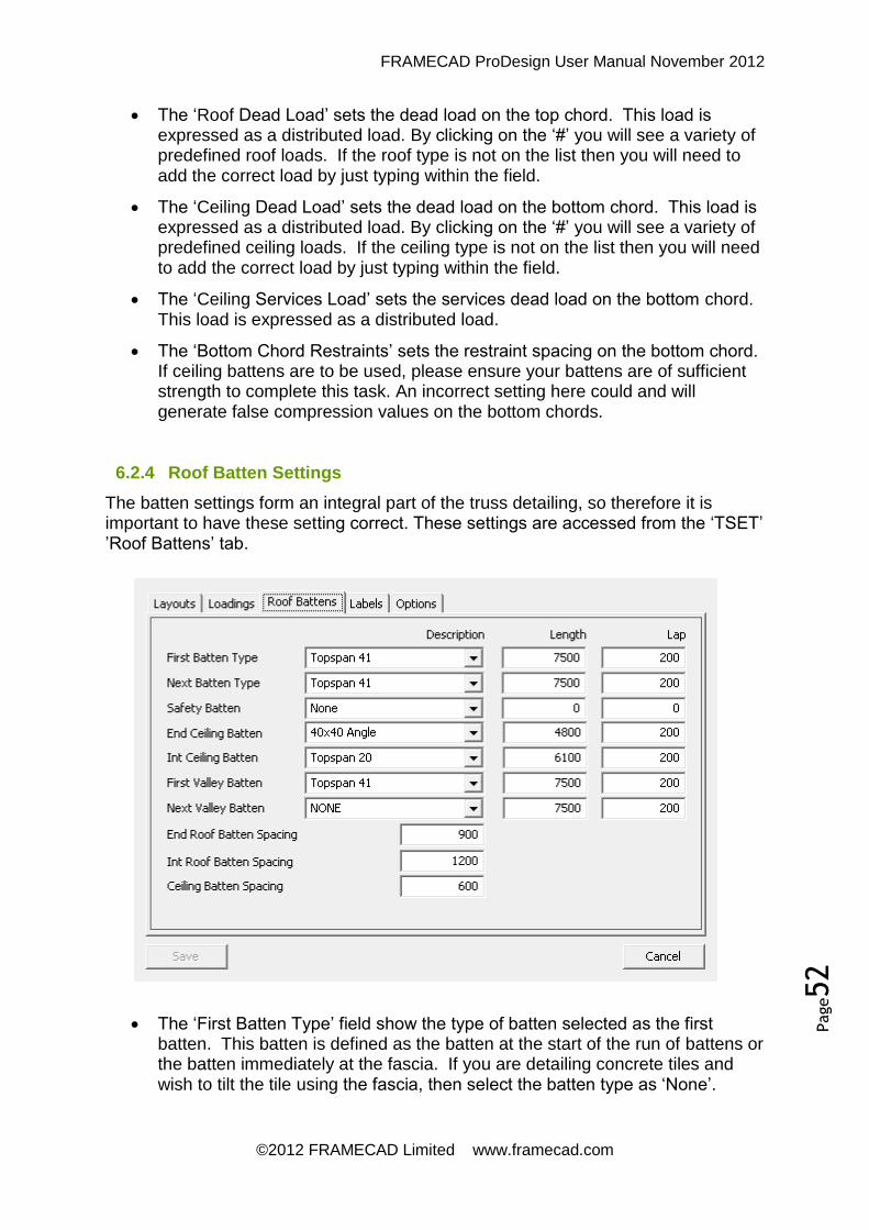
FRAMECAD ProDesign User Manual November 2012
©2012 FRAMECAD Limited www.framecad.com
Page52
The ‘Roof Dead Load’ sets the dead load on the top chord. This load is expressed as a distributed load. By clicking on the ‘#’ you will see a variety of predefined roof loads. If the roof type is not on the list then you will need to add the correct load by just typing within the field.
The ‘Ceiling Dead Load’ sets the dead load on the bottom chord. This load is expressed as a distributed load. By clicking on the ‘#’ you will see a variety of predefined ceiling loads. If the ceiling type is not on the list then you will need to add the correct load by just typing within the field.
The ‘Ceiling Services Load’ sets the services dead load on the bottom chord. This load is expressed as a distributed load.
The ‘Bottom Chord Restraints’ sets the restraint spacing on the bottom chord. If ceiling battens are to be used, please ensure your battens are of sufficient strength to complete this task. An incorrect setting here could and will generate false compression values on the bottom chords.
6.2.4 Roof Batten Settings
The batten settings form an integral part of the truss detailing, so therefore it is important to have these setting correct. These settings are accessed from the ‘TSET’ ’Roof Battens’ tab.
The ‘First Batten Type’ field show the type of batten selected as the first batten. This batten is defined as the batten at the start of the run of battens or the batten immediately at the fascia. If you are detailing concrete tiles and wish to tilt the tile using the fascia, then select the batten type as ‘None’.

FRAMECAD ProDesign User Manual November 2012
©2012 FRAMECAD Limited www.framecad.com
Page53
The ‘Next Batten Type’ field show the type of batten selected for the roof excluding the first batten. If the type of batten you wish to use is not on the list, then it will need to be added to the data file.
The ‘End Ceiling Batten’ field is the material used to support the ceiling battens at the end walls. If the type of batten you wish to use is not on the list, then it will need to be added to the data file. The ‘First Valley Batten’ field defines the type of material used as the valley support. The ‘Next Valley Batten’ is required in some systems require two types of materials for each valley support. That second type of material is selected here. If you don’t want to a second type of material then select ‘None’.
The ‘Length’ field sets the length of the. This length should be the actual ordering length of the batten.
The ‘Lap’ field sets the distance or overlap required when joining battens.
6.3 The Basic Operation
6.3.1 Quick Truss Command Reference
Command Usage
BSET Setup borders
REV Revision marking and updating feature
TSET Main truss settings
CRL Roof line wizard
TR Code as roof line
TS Code as support line
TH Code as a hanging beam
TCT or CT Codes lines as trusses
TIC Truss integrity check
TDT or DT Main truss layout engine
TLA or TL Label roof trusses
TFT Find a truss on a layout
TRB Add roof bracing to layout
STL Split a truss layout

FRAMECAD ProDesign User Manual November 2012
©2012 FRAMECAD Limited www.framecad.com
Page54
T3D Toggles 3D view on and off
TTC Cuts a single truss
TTM Cuts multiple trusses
TCE Rebuilds eaves
TVS Splits a truss
TBR Breaks a truss
TAD Add drawing to library
TAP Adds packers
TRL Amends Truss RL
ETG Erase Trusses
STH Converts a square end to a hex end
DH Dimensions horizontally
DV Dimensions vertically
DA Dimensions aligned
DOH Dimensions horizontally ordinate style
DOV Dimensions vertically ordinate style
DTH Dimensions trusses only horizontally
DTV Dimensions trusses only vertically
DL Dimensions lengths only
TLI Lists a truss
QT Quick text insertions
TID Insert Detail
TOD On sheet design summary
TOS On sheet truss summary
TOA On sheet accessories list
TOV On sheet verandah rafter summary
TTO Main truss takeoff
NTD Details all trusses
STD Details selected trusses
BT Builds a single truss
TFT Find a specified truss
PS Re-squares a truss member

FRAMECAD ProDesign User Manual November 2012
©2012 FRAMECAD Limited www.framecad.com
Page55
TSC Splices a truss chord
TBM Fully boxes a member
TBP Partially boxes a member
TEW Eases selected webs
TMI Mirrors selected webs
TAW Adds webs
TAN Analysis without report
TAR Analysis with report
TSF Shows truss failures
TAS Adds support points
TPL Adds point loads
TUS Updates a single cutting list
TUA Updates a multiple cutting list
TUR Creates a truss materials usage report
TXL Creates a truss materials usage export to Excel
TWH Re-calculates chord to web connection holes
TMH Re-calculates chord to chord connection holes

FRAMECAD ProDesign User Manual November 2012
©2012 FRAMECAD Limited www.framecad.com
Page56
6.3.2 RRS Creating Roof Shapes
The first part of any truss job is to draw the roof plan. There are several ways to achieve this. It could be drawn using basic cad commands, or you could import the roof plan if supplied in cad format.
However, if it is a regular roof shape you could use one of our wizards. The roof shape wizard is located under the ‘Roofing’ menu.
To access this command go
‘Roofing’ >> ‘Roof Layouts’ >>
‘RRS Create Roof Shape’. The hot key for this command is ‘RRS’.
To use this command, click on the required roof shape and follow the
prompts in the cad command area.
This will create a basic roof outline with pitching points and eave lines. To add the balance of the roof lines you will need to use the ‘CRL’ - ‘Create Roof Lines’
command which is described next.
6.3.3 CRL Creating Roof Lines
To create roof lines, use the ‘CRL’ command. The command is located on the ‘Trusses’ menu. To access the command ‘Trusses’ >> ‘Code As Routines’ >> ‘CRL Create Roof Lines’. It works on the basis that every roof is a block or a collection of blocks as was previously explained under the ‘Roof Block Theory’ section.
To use this command, you need to select three points on each roof block. The first two points selected represent one end of the roof block, the third point can be anywhere along the other end of the roof block. When selecting the roof points, the cursor is set to select end points or intersections.
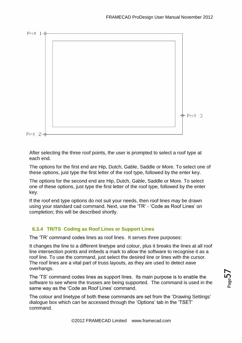
FRAMECAD ProDesign User Manual November 2012
©2012 FRAMECAD Limited www.framecad.com
Page57
After selecting the three roof points, the user is prompted to select a roof type at each end.
The options for the first end are Hip, Dutch, Gable, Saddle or More. To select one of these options, just type the first letter of the roof type, followed by the enter key.
The options for the second end are Hip, Dutch, Gable, Saddle or More. To select one of these options, just type the first letter of the roof type, followed by the enter key.
If the roof end type options do not suit your needs, then roof lines may be drawn using your standard cad command. Next, use the ‘TR’ - ‘Code as Roof Lines’ on completion; this will be described shortly.
6.3.4 TR/TS Coding as Roof Lines or Support Lines
The ‘TR’ command codes lines as roof lines. It serves three purposes:
It changes the line to a different linetype and colour, plus it breaks the lines at all roof line intersection points and imbeds a mark to allow the software to recognise it as a roof line. To use the command, just select the desired line or lines with the cursor. The roof lines are a vital part of truss layouts, as they are used to detect eave overhangs.
The ‘TS’ command codes lines as support lines. Its main purpose is to enable the software to see where the trusses are being supported. The command is used in the same way as the ‘Code as Roof Lines’ command.
The colour and linetype of both these commands are set from the ‘Drawing Settings’ dialogue box which can be accessed through the ‘Options’ tab in the ‘TSET’ command.

FRAMECAD ProDesign User Manual November 2012
©2012 FRAMECAD Limited www.framecad.com
Page58
Both the ‘TS’ and the ‘TR’ command allow the user to select either lines or polylines. However if you select a polyline, it will be converted to ordinary lines. This command will not work on heavy weight polylines. If you were to select a heavy weight poly line a warning will be issued.
Both roof and support lines may be copied, moved, extended, trimmed, mirrored or stretched using your standard cad commands. However you cannot use the offset command. Whilst it may appear to have worked, all intelligence is lost.
6.3.5 DT Detailing Truss and Veranda Layouts
The ‘TDT or ‘DT’ tool is used for the creation of roof layouts. Full truss, half truss or rafter input is determined in the ‘Detailing Type’ drop down box in ‘TSET’.
The ‘TDT’ command works very similar to the ‘CRL’ - ‘Create Roof Lines’ command, with the exception that with truss layouts you select the pitching points, not the eave
extremes. The pitching point is shown in the diagram.
When detailing a roof truss layout, you will be prompted for a roof type on each end; there are many options available here. Below is a table of available roof types.
When detailing half truss layouts, the first point selected is the high point of the roof truss. To make it easy to remember, just think you are up on the high edge of the roof and looking down.
The ‘DT’ rafter input mode works slightly different in that you need to select four points to define the parallelogram. Also the rafter input does not recognise eaves lines. If you need to include eaves, then you should include them within your point selection. Once again the rafter input is best if you assume that you are up on the high edge of the roof looking down.
FRAMECAD ProDesign User Manual November 2012
©2012 FRAMECAD Limited www.framecad.com
Page59
6.3.6 TLA Truss Labelling
To label the trusses, use the ‘TLA’ command. This command gives the option of selecting the required trusses or doing a global selection. If you select trusses, a secondary dialogue box will ask you what number you wish to start the labelling at. The height of the labelling text is currently fixed at the same height as the dimensioning text. Labelling prefixes can be altered in the ‘Labels’ tab in ‘TSET’.
6.3.7 TTO Truss Takeoff
As previously explained, the truss software two parts to it. To get the information from the layout to the detail sheets, you need to run a takeoff. The command for this is ‘TTO’. This command will then check your drawing for integrity and create an output file ready for truss building.
6.3.8 NTD/STD Truss Building
To actually build the trusses, you will need to start a ‘Truss Detail Dwg’. To do this from the menu go to ‘FILE’ >> ‘TRUSS DETAIL DWG’ and then select an appropriate drawing size. When you open this new drawing, you will see borders already set up. These borders are an integral part of the truss building process, so please do not explode or erase them.
After opening the new drawing, use the ‘NTD’ or ‘STD’ command to actually build the trusses. The two commands are almost identical, except that the ‘STD’ command allows you to select which trusses to import and detail, and the ‘NTD’ command will import and detail all trusses.
6.4 Truss Analysis
6.4.1 TAN/TAR Using Truss Analysis
Two tools have been provided for truss analysis, the ‘TAN’ ‘Truss Analysis’ and the ‘TAR’ - ‘Truss Analysis with Report’ command. Both commands operate identically, with the exception that the ‘TAR’ command also shows the report. For normal truss building with the ‘NTD’ or ‘BT’ command, the truss analysis works automatically. The only time one needs to run these commands is after doing manual alterations to trusses. The truss analysis will give one of five results:
1. Analysis Status = Passed
2. Analysis Status = Failed
3. Analysis Status = Support Failure
4. Analysis Status = Error
5. Analysis Status = Incorrect Data

FRAMECAD ProDesign User Manual November 2012
©2012 FRAMECAD Limited www.framecad.com
Page60
If you try to analyse a non-structural item, e.g. ceiling tie, then no action will occur. If there is more than one truss in the current border then the outcome could generate inconsistent or unreliable results.
‘Passed’ means that with the information supplied, the truss is within the design code limits as set in the truss loading settings. When a truss has passed, all members on that truss are automatically re labelled and the cutting lists are updated.
‘Failed’ means that with the information supplied, the truss is outside the design code limits as set in the truss loading settings. This means that the truss will need to be reconfigured in some form to pass analysis. The appendix in the rear of this manual will give some assistance in this area. When a truss fails, the members are not labelled, and no cutting lists are generated.
‘Support Failure’ means the failure occurs when the software detects less than two support points on the truss. In this case you need to check to see if the lack of supports is genuine, if not, you can use the ‘TAS’ command to add the required support points and reanalyse. If the lack of supports is genuine, then a structural engineer’s advice should be sort.
‘Error’ occurs when the analysis engine has generated an internal error. This could occur when the software malfunctions or when there is a total and absolute truss failure. If it is a software malfunction, then a copy of the truss should be forwarded to the software developers for debugging.
‘Incorrect Data’ occurs when your data file is out of date in this case you will need an updated data file. For this you should contact you network administrator or software support person.
6.4.2 Hints on Fixing Truss Failures
In all cases, reducing the load on the truss by either reducing the truss spacing or adding additional support points will fix failure problems. However, if this is not possible then the guidelines below may help. If a chord has failed with a failure of greater than 200%, then there is nothing that can be done to that truss with the exception of reducing the load on the truss. In all cases, you will need to go back to the layout and find additional internal supports or redo the layout with an alternate configuration.
Compression Failures
1. If a top or bottom chord, decrease panel point spacing.
2. For bottom chords, chord restraint spacing could be reduced.
3. For webs, add a midpoint web restraint.
4. The gauge thickness or size of the member could be increased.
5. Boxing of the member could also assist.
Shear Failures
1. The gauge thickness or size of the member could be increased.
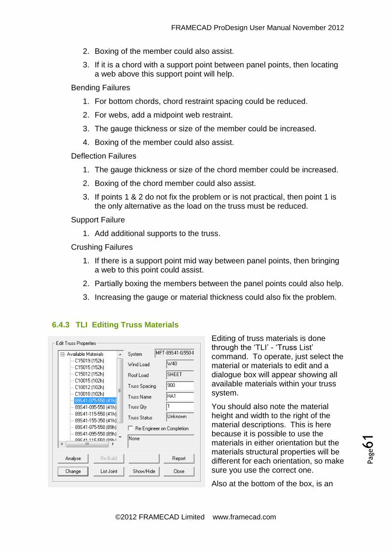
FRAMECAD ProDesign User Manual November 2012
©2012 FRAMECAD Limited www.framecad.com
Page61
2. Boxing of the member could also assist.
3. If it is a chord with a support point between panel points, then locating a web above this support point will help.
Bending Failures
1. For bottom chords, chord restraint spacing could be reduced.
2. For webs, add a midpoint web restraint.
3. The gauge thickness or size of the member could be increased.
4. Boxing of the member could also assist.
Deflection Failures
1. The gauge thickness or size of the chord member could be increased.
2. Boxing of the chord member could also assist.
3. If points 1 & 2 do not fix the problem or is not practical, then point 1 is the only alternative as the load on the truss must be reduced.
Support Failure
1. Add additional supports to the truss.
Crushing Failures
1. If there is a support point mid way between panel points, then bringing a web to this point could assist.
2. Partially boxing the members between the panel points could also help.
3. Increasing the gauge or material thickness could also fix the problem.
6.4.3 TLI Editing Truss Materials
Editing of truss materials is done through the ‘TLI’ - ‘Truss List’ command. To operate, just select the material or materials to edit and a dialogue box will appear showing all available materials within your truss system.
You should also note the material height and width to the right of the material descriptions. This is here because it is possible to use the materials in either orientation but the materials structural properties will be different for each orientation, so make sure you use the correct one.
Also at the bottom of the box, is an

FRAMECAD ProDesign User Manual November 2012
©2012 FRAMECAD Limited www.framecad.com
Page62
option to ‘Re-Engineer’. If ticked, the truss will be automatically re-engineered after editing of the materials.
Once you have changed materials, you will notice that the cutting lists are automatically updated.
6.4.4 Listing a Truss Joint
There is an option in the ‘TLI’ dialogue box to ‘List Joint’ for the purpose of listing each truss joint. This command will bring up a dialogue box showing all available data.
The ‘First Fixing Capacity’ refers to the allowed capacity of the first fixing type. Currently the software allows for a maximum of two fixing types per system, but this will be changing in the near fixing.
The ‘Second Fixing Capacity’ refers to the allowed capacity of the every other fixing after the first fixing type.
The ‘Joint Capacity’ is the total capacity of fixings at that joint.
The ‘Applied Load’ is the total load on that joint as determined by the truss analysis.
6.4.5 TBM/TBP Boxing Truss Members
To box a truss member, use the ‘TBM’ - ‘Truss Box Member’ command. This command will fully box a truss member. This command also has the added feature in that not only will it box a member, but it will also un-box a member if it is already boxed.
When using the command to un-box, you are better off selecting the member(s) with a crossing, this is the only sure way of selecting the correct member.
If you wish to only partially box a member, use the ‘TBP’ - ‘Truss Box Partial’ command. This command requires you to select two points, the starting point and the ending point. This command will not un-box a member, to un-box a partially boxed member use the ‘TBM’ command.
6.4.6 TWR Add Web Restraint
The ‘TWR’ - ‘Truss Web Restraint’ will add a restraint to any webs. To use the command just select a point on the web where you require the restraint.
WARNING: When adding a web restraint make sure it is noted on the layouts so you can be sure this restraint will be added on site, as this will be a structural requirement.
6.4.7 Truss Member Loads
Various parts of a truss have different load conditions applied. For the definition of various truss parts, please refer to the definitions section of this manual. So if you

FRAMECAD ProDesign User Manual November 2012
©2012 FRAMECAD Limited www.framecad.com
Page63
copy parts of a truss, ensure you use the correct member for the load condition required. Failure to do this will create an inaccurate analysis result.
Top Chord
Bottom Chord
Horiz Chord
Web Rail Verandah
Rafter
Live Roof Load
Yes Yes Yes
Live Ceiling Load
Yes
Dead Roof Load
Yes Yes Yes
Dead Ceiling Load
Yes Yes
Service Load
Yes
Snow Load
Yes Yes Yes
External Wind Load
Yes Yes Yes
Internal Wind Load
Yes Yes
The only exception to the above would be a girder truss. The bottom chord of a girder truss would also carry the imposed load of the oncoming bridge trusses.

FRAMECAD ProDesign User Manual November 2012
©2012 FRAMECAD Limited www.framecad.com
Page64
6.5 Advanced Truss Layout Tools
6.5.1 TVC Visual Controls
Sometimes truss layouts become very confusing, with lines of top of lines. FRAMECAD Pro has provided a tool called ‘TVC’ - ‘Truss Visual Control’ to allow the operator to easily show or hide various aspects of a truss layout.
The command is located on the dropdown menus, to access go ‘TRUSSES’ >> ‘TVC Visual Controls’. By clicking on the desired tick box various aspects will be shown or hidden.
Alternately you could also just use the CAD systems standard ‘Layer’ command.
6.5.2 CT Code Line As Truss
Sometimes when detailing roofs, you want a truss at a specific location but the software will not automatically do it. In those circumstances the routine ‘CT’ has
been provided. The operator is required to draw the line, which represents the truss then use the ‘TCT Code Line as Truss’ routine.
When the command is first activated, a dialogue box appears. Select the required truss type, pitch and truss spacing. If applicable also select the required truss height and dutch rail height location.
When selecting the line to code as truss, the end closest to the point selected will be the starting end or left hand end. This is especially important with half trusses, as eaves are only added to the starting end of a half truss.
The ‘D’ field beside the toe height field, restores the toe height to the default
value.
If the ‘Create By Points’ box is ticked, then the user is prompted to select both the starting and finishing ends of the new truss. If it is unticked, the user is required to select an existing line to convert to a truss.
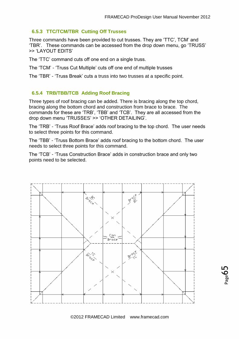
FRAMECAD ProDesign User Manual November 2012
©2012 FRAMECAD Limited www.framecad.com
Page65
6.5.3 TTC/TCM/TBR Cutting Off Trusses
Three commands have been provided to cut trusses. They are ‘TTC’, TCM’ and ‘TBR’. These commands can be accessed from the drop down menu, go ‘TRUSS’ >> ‘LAYOUT EDITS’
The ‘TTC’ command cuts off one end on a single truss.
The ‘TCM’ - ‘Truss Cut Multiple’ cuts off one end of multiple trusses
The ‘TBR’ - ‘Truss Break’ cuts a truss into two trusses at a specific point.
6.5.4 TRB/TBB/TCB Adding Roof Bracing
Three types of roof bracing can be added. There is bracing along the top chord, bracing along the bottom chord and construction from brace to brace. The commands for these are ‘TRB’, ‘TBB’ and ‘TCB’. They are all accessed from the drop down menu ‘TRUSSES’ >> ‘OTHER DETAILING’.
The ‘TRB’ - ‘Truss Roof Brace’ adds roof bracing to the top chord. The user needs to select three points for this command.
The ‘TBB’ - ‘Truss Bottom Brace’ adds roof bracing to the bottom chord. The user needs to select three points for this command.
The ‘TCB’ - ‘Truss Construction Brace’ adds in construction brace and only two points need to be selected.

FRAMECAD ProDesign User Manual November 2012
©2012 FRAMECAD Limited www.framecad.com
Page66
6.5.5 Dimensioning Roof Trusses
Four commands are sufficient to dimension most roofs. These commands are ‘DH’, ‘DV’, ‘DA’ and ‘DO’. The ‘DH’, ‘DV and ‘DA’ commands produce regular style
dimensions where as the ‘DO’ command produces ordinate style dimensions.
All commands require the operator to select three points, the first being the location for the dimensions, and the second and third points are the starting and finishing points for the dimensions.
6.5.6 TIC Layout Integrity Checks
This command is a quick way of checking for drafting errors or simple oversights. The command name is ‘TIC’ - ‘Truss Integrity Check’. It can be accessed from the main ‘Trusses’ drop down menu. If any errors are found, then a warning box will appear showing what errors were suspected. Different levels of warnings can be preset within the data file, so not all systems have the same warnings. However most systems will check for the presence of roof bracing and warn on trusses over the maximum length.
6.5.7 Do’s and Don’ts of CAD Commands
Whilst our software operates within the cad environment, not all cad commands are compatible. The two main commands which cause big problems are the ‘OFFSET’ command and the ‘MIRROR’ command.
Whilst the offset command may appear to have worked, in many if not all cases it does not copy the intelligence with the associated entity. An example of this would be if you offset a roof line, it looks like it has offset the entity okay, but the new item now is only a line, it has lost all intelligence. Whilst this is a problem, if you are aware of it, the command can still be useful.
Be very aware about using the ‘MIRROR’ command. Its results can be unreliable. If you must use it just be aware.

FRAMECAD ProDesign User Manual November 2012
©2012 FRAMECAD Limited www.framecad.com
Page67
6.6 Layout Reports and Printing
6.6.1 TOS/TOD/TOV On Sheet Summaries
There are currently four available on sheet reports, the ‘TOS’, ‘TOD’, ‘TOV’ and the ‘TOA’ commands. These are designed as short summaries intended to adorn the roof truss layout.
The ‘TOS’ - ‘Truss Onsheet Summary’ gives a short summary of the truss types used on the truss layout.
The summary includes quantities and a tally of bottom chord lengths.
The ‘TOD’ - ‘Truss Onsheet Design’ summary gives a brief summary of the design including various critical settings.
This summary is possibly the most important summary as it shows the operator has used the correct loading methods.
The ‘TOA’ - ‘Truss Onsheet Accessories’ summary given a list of other associated item required to go with the roof trusses.
This command has a settings dialogue box associated with it containing many options.
By pressing the ‘Default’ button, the default options will be restored from your truss data file. Currently there is no way to set a default, except by direct editing the data file.
6.6.2 TLR Printable Reports
Currently there is only one layout report available. This is the ‘TLR’ - ‘Truss Layout Report’. Through this report you may export to a text file or a CSV type file and print to a printer. The options menu allows you to hide or show components, brackets and fasteners.

FRAMECAD ProDesign User Manual November 2012
©2012 FRAMECAD Limited www.framecad.com
Page68
6.6.3 PRIA Printing the Layouts
If you are using IntelliCAD Version 5 or above, we have provided a spool printer that will print all views through one command. The command for this is ‘PRIA’. It has an options dialogue box associated with it containing several settings.
Here you can select the appropriate printer, paper size, number of copies etc. Once you press ‘GO’ all views will be printed automatically.
6.7 Definitions
6.7.1 Truss Marker Definition
The truss marker that is drawn on truss layouts refers to the face of the truss with the truss sitting on the marker.
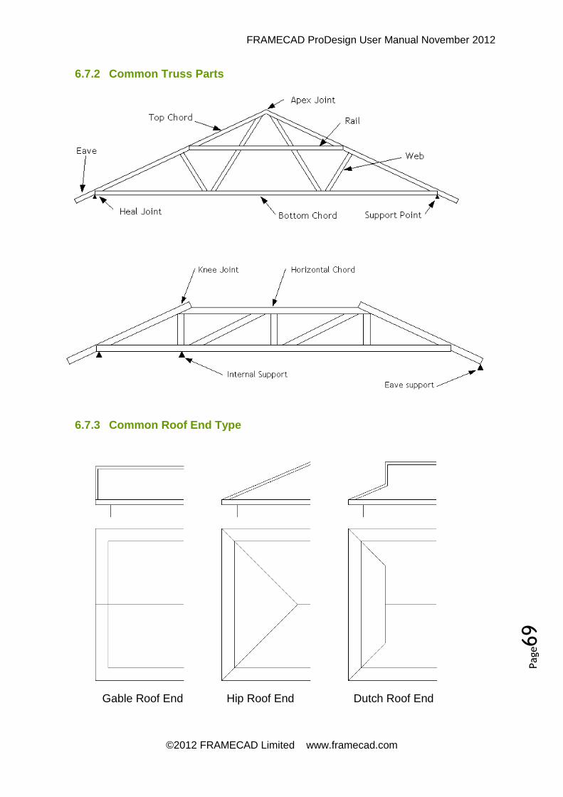
FRAMECAD ProDesign User Manual November 2012
©2012 FRAMECAD Limited www.framecad.com
Page69
6.7.2 Common Truss Parts
6.7.3 Common Roof End Type
Gable Roof End Hip Roof End Dutch Roof End

FRAMECAD ProDesign User Manual November 2012
©2012 FRAMECAD Limited www.framecad.com
Page70
Dialogue Styles
Most of the ‘FRAMECAD Pro’ dialogue boxes use a smart colour system. When the software changes a value automatically, the colour of the text usually changes to ‘RED’. When the user changes a value, the colour of the text usually changes to ‘BLUE’.
7.1 Command Reference
Command Usage
BSET Border setup
REV Revision notes
DA Dimension aligned
DL Dimension lengths
DH Dimension horizontally
DV Dimension vertically
DJH Dimension joists horizontally
DJV Dimension joists vertically
DOH Dimension horizontally ordinate style
DOV Dimension vertically ordinate style
FJSET Floor sheet setup
FO Offset a trace
IP Inherit properties
J3D Floor to 3D
JAD Add a detail drawing
JAM Add a member to data file
JAP Add a part to data file
JAS Add a sectional properties to data file
JBP Create a bracket plan
JCNC Generate CNC output
JD Detail a floor layout
7 Floor Layouts

FRAMECAD ProDesign User Manual November 2012
©2012 FRAMECAD Limited www.framecad.com
Page71
JDF Detail floor sheeting
JEG Erase guides
JFJ Find a floor member
JIC Floor integrity check
JID Insert a detail drawing
JIM Insert a member
JIS Insert service holes
JJC Cut a floor member
JJD Detail webbed floor joists
JJM Cut multiple floor members
JLA Label floor members
JLI List a floor member
JLR Layout report
JOB Onpage bracket report
JOF Onpage sheeting report
JOS Onpage member summary
JP1 Detail purlins
JP2 Add holes to purlins
JSET Main floor settings
JSS Show members starting edge
JSV Create a sectional view
JSW Show web side
JTO Take off webbed joists
JUA Update all webbed joist cutting lists
JUR Joist usage report
JUS Update single webbed joist cutting lists
JWB Detail a single webbed beam
PC Cut a trace
PE Extend a trace
PJ Join a trace
PT Trim a trace
QST Insert a steel section profile

FRAMECAD ProDesign User Manual November 2012
©2012 FRAMECAD Limited www.framecad.com
Page72
SW Show old wall layer
SWA Add to old wall layer
ULE Run of engaged piers
ULI Run of isolated piers
ULP Run of steel posts
URU Rough in under floor plan
USE Insert single engaged pier
USET Under floor settings
USI Insert single isolated pier
USP Insert single steel post
7.2 New Layout Drawing
See 5.1 New Layout Drawing
7.3 BSET Border Setups
Refer Section 5.2
7.4 JSET Floor Settings
This is the main setup routine for floor detailing. This command may be accessed directly from the menu, or directly from the command line as ‘JD’. Each field is
explained here in detail.

FRAMECAD ProDesign User Manual November 2012
©2012 FRAMECAD Limited www.framecad.com
Page73
‘Current System’ - This field contains the name of the floor system to be used. System files are kept in the ‘\Tanmari\Framing Module\Library’ folder and all floor files have a file extension of ‘.da7’.
‘End Bearer Type’ - This field shows the type of ‘End Bearer’ to be used. The image to the right of the dialogue box will show the definition of an ‘End Bearer’. This image is a dynamic image which changes as each field receives focus. An ‘End Bearer’ is a member that carries terminating joints. If you do not wish to use any ‘End Bearer’ select ‘None’ from the drop down box.
‘Side Bearer Type’ - This field shows the type of ‘Side Bearer’ to be used. The image to the right of the dialogue box will show the definition of an ‘Side Bearer’. This image is a dynamic image which changes as each field receives focus. A ‘Side Bearer’ is a member that usually does not carry joints. If you do not wish to use any ‘Side Bearer’ select ‘None’ from the drop down box.
‘Internal Bearer Type’ - This field shows the type of ‘Internal Bearer’ to be used. The image to the right of the dialogue box will show the definition of an ‘Internal Bearer’. This image is a dynamic image which changes as each field receives focus. An ‘Internal Bearer’ is a member that usually carries joists on each side. If you do not wish to use any ‘Internal Bearer’ select ‘None’ from the drop down box.
‘Joist Type’ - This field shows the ‘Joist’ type to be used. The image to the right of the dialogue box will show the definition of a ‘Joist’. This image is a dynamic image which changes as each field receives focus. The value used here will be dictated by the available engineering, and the type of floor sheeting used.
‘Joist Spacing’ - In this field, the spacing of the joists are set. Normally this field is a multiple of 150, however under some circumstances this may need to be changed.
‘Internal Bearer Spacing’ - This field is the spacing of the ‘Internal Bearers’. The value used here will be dictated by the available engineering.

FRAMECAD ProDesign User Manual November 2012
©2012 FRAMECAD Limited www.framecad.com
Page74
The ‘Floor Datum’ function is only used when you view the floor system in 3D, or generate accurate sectional views.
The ‘Dead Load’ sets the dead load on the joist. This load is expressed as a distributed load. There is a button to the left of this field. By pressing this button you will see a variety of predefined loads.
The ‘Live Load’ sets the live load on the joist. This load is expressed as a distributed load.
The ‘Ceiling Load’ sets the ceiling load on the joist. This load is expressed as a distributed load. There is a button to the left of this field. By pressing this button you will see a variety of predefined loads.
The ‘Snow Load’ sets the snow load on the joist. This load is expressed as a distributed load.
The ‘Inline End Bearers’ toggle will set the ‘End Bearers’ to be located inline if this box is ticked. If the box is unticked, then the ‘End Bearers’ will be located under the ‘Joists’. The image in the dialogue box will show the definition of this. This image is a dynamic image which changes as each field receives focus.
The ‘Inline Int Bearers’ toggle will set the ‘Internal Bearers’ to be located inline if this box is ticked. If the box is unticked, then the ‘Internal Bearers’ will be located under the ‘Joists’. The image in the dialogue box will show the definition of this. This image is a dynamic image which changes as each field receives focus.
If the ‘Double Int Bearers’ tick box is ticked, then double internal bearers will be used. If it is unticked, then only a single bearer will be used. The value used here will be dictated by the available engineering.
‘More’ Options Button
The ‘Floor Label Options’ is explained in a section below. The ‘Cutting List Options’ are also explained in a section below.
The ‘Save As Default’ option means that after ‘Saving As Default’, every time you restore this system, then these ‘Save As Default’ options will be reloaded.
The ‘Save As A Model’ means that if desired all settings in the ‘JSET’ dialogue box
can be saves as a model, making it available for future restoration. When you save as a model, a dialogue box appears where you can enter a short description. But please keep this description very short.
The ‘Restore A Model’ will restore any previously saved settings. This can be very
useful, as it saves having to reselect members every time.
The ‘Delete a Model’ will remove a model from the data file.
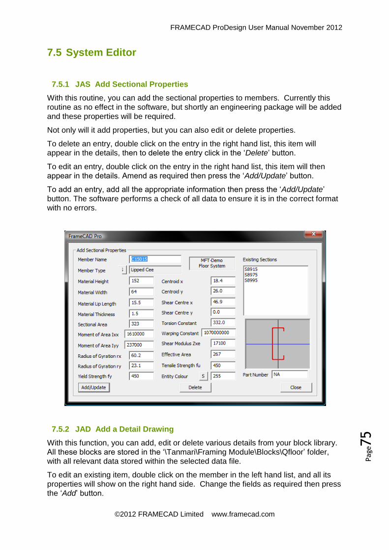
FRAMECAD ProDesign User Manual November 2012
©2012 FRAMECAD Limited www.framecad.com
Page75
7.5 System Editor
7.5.1 JAS Add Sectional Properties
With this routine, you can add the sectional properties to members. Currently this routine as no effect in the software, but shortly an engineering package will be added
and these properties will be required.
Not only will it add properties, but you can also edit or delete properties.
To delete an entry, double click on the entry in the right hand list, this item will appear in the details, then to delete the entry click in the ‘Delete’ button.
To edit an entry, double click on the entry in the right hand list, this item will then appear in the details. Amend as required then press the ‘Add/Update’ button.
To add an entry, add all the appropriate information then press the ‘Add/Update’
button. The software performs a check of all data to ensure it is in the correct format with no errors.
7.5.2 JAD Add a Detail Drawing
With this function, you can add, edit or delete various details from your block library. All these blocks are stored in the ‘\Tanmari\Framing Module\Blocks\Qfloor’ folder, with all relevant data stored within the selected data file.
To edit an existing item, double click on the member in the left hand list, and all its properties will show on the right hand side. Change the fields as required then press the ‘Add’ button.
FRAMECAD ProDesign User Manual November 2012
©2012 FRAMECAD Limited www.framecad.com
Page76
To delete an existing member, double click on the member in the left hand list, and all its properties will show on the right hand side. Press the ‘Delete’ button and the item will be removed from the list and the associated data file. Also note that the
block will be deleted.
To add a new item, double click on an existing detail in the left hand list, and all its properties will show on the right hand side. Change the fields as required then press the ‘Add’ button. The dialogue box will disappear and then you will be prompted to
select the block, followed by the blocks insertion point.
In the ‘Drawing Name’ field you must insert drawing name. The name should be short and sweet and should not contain any spaces. The extension ‘.dwg’ is not
necessary and should not be used.
The ‘Description’ field allows you to enter a short description so you can identify its
intended use. There is no limit to its length, but shorter is better.
7.5.3 JAP Add a Part
This routine allows you to add, edit or delete parts.
To delete an entry, double click on the entry in the right hand list, this item will appear in the details, then click in the ‘Delete’ button.
To edit an entry, double click on the entry in the right hand list, this item will then appear in the details. Amend as required then press the ‘Add/Update’ button.
To add an entry, add all the appropriate information then press the ‘Add/Update’
button. The software performs a check of all data to ensure it is in the correct format
with no errors.
7.5.4 JAM Add a Member
This routine gives you the capacity to add, edit or delete members at will. The members that appear here are the members that appear in the ‘JSET’ routine. All
fields are required and MUST be filled in accurately. All fields are self explanatory with exception to the ‘Orientation’ field.
The ‘Orientation’ field sets the direction of ‘Channel’, ‘Lipped Cee’ or ‘Open Cee’ members. It does not affect symmetrical sections. This field consists as a group of four numbers, either 0 or 1. Zero means that the toes or open side face outwards. One means that the toes or open face faces inwards. The first digit refers to ‘End Bearers’, the second digit refers to ‘Side Bearers’, the third digit refers to ‘Internal
Bearers’ and the fourth and last item refers to ‘Joists’.
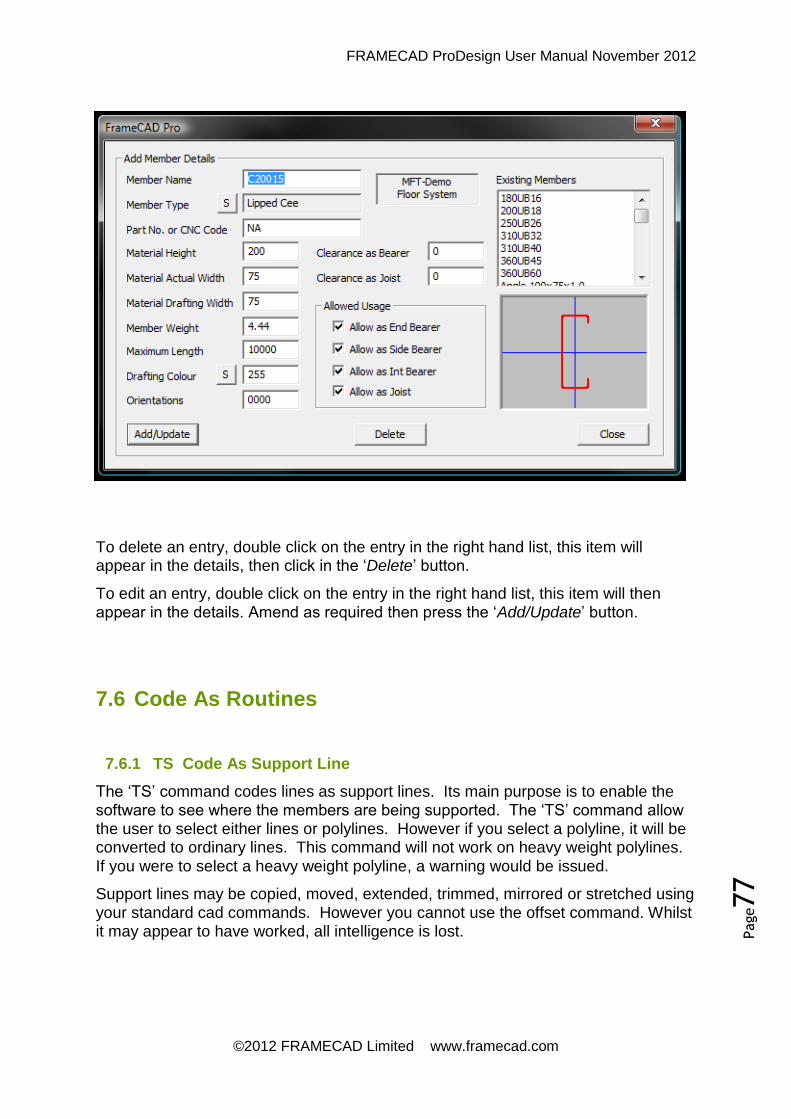
FRAMECAD ProDesign User Manual November 2012
©2012 FRAMECAD Limited www.framecad.com
Page77
To delete an entry, double click on the entry in the right hand list, this item will appear in the details, then click in the ‘Delete’ button.
To edit an entry, double click on the entry in the right hand list, this item will then appear in the details. Amend as required then press the ‘Add/Update’ button.
7.6 Code As Routines
7.6.1 TS Code As Support Line
The ‘TS’ command codes lines as support lines. Its main purpose is to enable the software to see where the members are being supported. The ‘TS’ command allow the user to select either lines or polylines. However if you select a polyline, it will be converted to ordinary lines. This command will not work on heavy weight polylines.
If you were to select a heavy weight polyline, a warning would be issued.
Support lines may be copied, moved, extended, trimmed, mirrored or stretched using your standard cad commands. However you cannot use the offset command. Whilst it may appear to have worked, all intelligence is lost.

FRAMECAD ProDesign User Manual November 2012
©2012 FRAMECAD Limited www.framecad.com
Page78
7.7 Layout Commands
7.7.1 JD Detail Floor
This is the main command used to detail a floor. To use this command, all you need to do is select the boundaries of the floor you wish to detail. The boundaries could be either lines or polylines and should be a closed area. The boundaries could consist on any shape or collection of shapes and several separate boundaries could be included.
When this command is first initiated you are prompted to select the boundaries or press ‘Enter’ for set up. If you press ‘Enter’ you will be taken to the ‘JSET’ command.
On completion of ‘JSET’ you will be returned to this routine.
Once the boundaries have been selected, you will be prompted for a set out point. This is the point from which all the joists are set from.
Next you will be prompted for the direction of the joists. Here you could just drag the mouse in the direction required and press ‘Enter’ or select a point to in reference to
the set out point or just enter an angle for the joist direction.
7.7.2 JLI List a Floor Member
With this command you may list and amend floor members as necessary. Currently it will only amend the first member found.
After selecting a member, the starting end of the member is marked with a yellow
marker with the finishing end marked with a red marker.
As far as editing goes, there are some options you can change or if really desired, you can show the member as a line or if already a line, you can re-expand the member to full width.
7.7.3 JFJ Find a Member
Sometimes floor layouts can get very complex. And sometimes you can never find that joist you are looking for. With this command, all you do is enter the joist or
member number and a marker will show you its location.
7.7.4 JLA Label Members
This routine labels all floor members. When the command is first initiated, you are prompted to select the members to label or return for global selection.
If you have opted to select members to label, then you will prompted to set the starting number of the labelling. This is very useful for labelling a job with more than
one level of floors.
When selecting members for global or individual numbering, any previous text labels selected will be deleted.

FRAMECAD ProDesign User Manual November 2012
©2012 FRAMECAD Limited www.framecad.com
Page79
Members will be labelled in the format that was set with ‘JSET’ ‘Labelling Options’.
All members are labelled from the top left corner radiating outwards. The height of the text will be the same as the variable setting ‘DIMTXT’.
7.7.5 QST Steel Sections
This function is a utility for generating profiles of standard steel sections.
All member shapes, sizes and profiles are contained within the systems data file. Members may be inserted at any scale with the ability to rotate the section after
insertion.
When each section is generated, it is generated as a single polyline. Should the need arise, it may be exploded or edited as
required.
7.8 Other Detailing
7.8.1 JDF Floor Sheeting
This command is used to create floor
sheet layouts. The command works similar to the ‘JD’ command. All you need to do is select the boundaries of the floor you wish to add sheeting to. The boundaries could be either lines or polylines and should be a closed area. The boundaries could consist on any shape or collection of shapes and several separate boundaries could be
included.
Once the boundaries have been selected, you will then be prompted for a set out point. This is the point from which all the sheeting is set from. Once the sheeting is detailed, a small circle is drawn at this setout point.

FRAMECAD ProDesign User Manual November 2012
©2012 FRAMECAD Limited www.framecad.com
Page80
Next you will be prompted for the direction of the joists. Drag the mouse in the direction required and press ‘Enter’ or select a point in reference to the set out point
or just enter an angle for the joist direction.
When this command is first initiated, you are prompted to select the boundaries or press ‘Enter’ for set up. If you press ‘Enter’ you will be takes to the floor sheeting
options. On completion of the settings, you will be returned to this routine.
To select a new sheet type, click on the dropdown box for all available options. If the option desired is not on the list, then contact your systems administrator as there is currently no options available for the user to
add additional sheeting.
7.8.2 JID Insert a Detail Drawing
This routine allows the user to insert special details into their drawing. When the command is initiated, a list box appears
showing a list of all available details.
The ‘Drawing Insertion Scale’ field allows
the user to alter the scale of the drawing if desired.
By using the ‘JAD’ command the user is
able to add details as they are created.
7.8.3 JIM Insert a Member
With this command, you have the facility to add a member into the floor layout at any desired location. To use this command, you need to select a ‘Member Type’ from the list,
set the correct ‘Member RL’, plus any other desired settings, then select two points
where you want the member inserted.
In some cases it could be a good idea to draw in a temporary construction line, and use this as your insertion points.
Once the two points have been selected, you are prompted for a side to offset the member. If a side is not selected, then the member is inserted along the centre line.
If the ‘Double Member’ box is ticked, then
two members will be inserted side by side. The orientation of the members is governed by the data contained within the data file.

FRAMECAD ProDesign User Manual November 2012
©2012 FRAMECAD Limited www.framecad.com
Page81
If the ‘Show as Line’ is ticked then the member will not be drawn with thickness.
This can be useful when inserting a member underneath a floor.
If the ‘Cut in Member’ box is ticked, then the new member will be cut into the existing floor erasing a section from the existing floor equal to the width of the member
inserted.
7.8.4 J3D Create 3D View
‘Floor’ is mainly a 2D program. However this function creates a full wire frame
diagram of the floor system. This is a very handy function when checking very
complex jobs with many floor levels.
To remove the 3d entities just use this command again. If 3D floors are found they will be deleted, if no 3D floors are found then they will be created.
All 3D floors are created on a layer called ‘3D_Floor’ and the 3D colours will be
similar to the original entities.
7.8.5 JSC Create Section
This command creates a sectional view between any two given points. This command has no other options. The command is very useful when you need to show joist or member orientations.
To use the command, you need to select three points, the first point is the location of the sectional view, the second and third points are the staring point and ending point
of the section.
First Point
Selected
Second Point
Selected
Third Point
Selected

FRAMECAD ProDesign User Manual November 2012
©2012 FRAMECAD Limited www.framecad.com
Page82
7.8.6 JIS Insert a Service Line
This command is only used by systems where machinery and CNC can cater for the processes of service penetrations in floor members. To see if you can use this
provision, please contact your systems administrator.
To use the command, you need to select two points, representing the starting and finishing points of the run of service holes. The software will then draw a line between these two points with imbedded information within. This line is drawn on a layer called ‘Service_Hole’.
7.9 Floor Edits
7.9.1 JEG Erase Guides
Usually when drawing or roughing in floor systems, guide lines and temporary lines are often drawn. To erase these guides is sometimes difficult but with this command you can select the whole region and only items not associated with the floor layout will be erased.
The biggest trick to good detailing is to create a clean and accurate drawing that is
pleasing to the eye. This function is a great aid in achieving this.
Second Point
Selected Third Point
Selected
First Point
Selected

FRAMECAD ProDesign User Manual November 2012
©2012 FRAMECAD Limited www.framecad.com
Page83
7.9.2 JIC Integrity Check
This command performs some basic member checks. At the time of writing, the only check performed was a check for floor members exceeding the maximum allowed length.
The maximum allowed lengths have been preset within
the data file.
Any member found is marked with a red marker and an
alert box warning is issued.
7.9.3 JSW Show Web Side
This command will show which side of the member is the web side. This only applies to ‘Cee Section’ or ‘Lipped Cee Section’ members as there is no need to use
this with symmetrical members or closed sections.
7.9.4 JSS Show Start
Every member has a starting end and a finishing end. This command will mark the starting end and finishing end of all members. The starting end is marked with a yellow marker and the finishing end is marked with a red marker.
Normally the members are orientated with the starting end being the left or the top
side.
7.9.5 JEX Shrink/Expand Members
This command is a toggle. It reduces members to a drafting width or expands
members to full width.
With some systems the drafting width is different from the members actual width. From a detailing or calculation point of view, the drafting width is desired, but from a presentation the actual width is desired. This command gives you the best of both
worlds.
7.9.6 JJC Cut a Single Member
This function cuts a member at a given point. When this command first initiates, you can select a member or return for setup. The setup allows you to initiate the ability to
update the cut end types.
To operate, first select the member to cut, and then select the point where you wish to cut the member. When selecting the cutting point, the cursor snap mode has been set to select an end point or intersection. If needed, you may wish to draw in a guide
line to represent the cutting point.
If the options were set to update end types, then a dialogue box would appear asking you to select the appropriate end type for that particular member, the current member end type should be highlighted. This dialogue box also shows a slide view
of the end type.

FRAMECAD ProDesign User Manual November 2012
©2012 FRAMECAD Limited www.framecad.com
Page84
7.9.7 JJM Cut Multiple Members
This command operates similarly to ‘JJC’ except here you can cut many members at
once.
To use this routine, you need to select two points to represent the cutting line. All members intersecting these two points will be cut. When selecting the cutting point, the cursor snap mode has been set to select an end point or intersection. If needed
you may wish to draw in a guideline to represent the cutting point.

FRAMECAD ProDesign User Manual November 2012
©2012 FRAMECAD Limited www.framecad.com
Page85
7.10 Under Floor Plans
7.10.1 USET Under Floor Settings
This sets the main parameters for all under floor detailing. This is where all pier
sizes and spacing are set
When ‘USET’ is first initialized, it scans the current drawing for active
settings. If no active settings are found, then it retrieves settings from any previously detailed under floors in the current drawing. If still no settings are found then it retrieves the last used settings from the system registry.
If no last used settings are found, then the default settings are used. When the default settings are used, a warning is issued, as it is most likely that these settings will need to be changed.
When exiting via the OK button, all settings are saved in the current drawing and also in the system’s registry. If the CANCEL button was pressed, then no settings
are changed, and the drawing plus system’s registry remain unchanged.
The drawing below explains what each parameter means.
Engaged Pier
Width
Engaged Pier
Spacing
Engaged Pier
Depth
Bearer
Spacing
Isolated Pier
Spacing
Isolated Pier
Size

FRAMECAD ProDesign User Manual November 2012
©2012 FRAMECAD Limited www.framecad.com
Page86
7.11 Dimensioning
7.11.1 DH Dimension Horizontally
This routine will dimension horizontally from point to point. Select the dimension location then select the points you wish to dimension. When selecting points to dimension, the cursor has been set to pick end points or intersections. This routine will only dimension using the ‘X’ coordinates.
7.11.2 DV Dimension Vertically
This routine will dimension vertically from point to point. Select the dimension location then select the points you wish to dimension. When selecting points to dimension, the cursor has been set to pick end points or intersections. This routine will only dimension using the ‘Y’ coordinates.
7.11.3 DA Dimension Aligned
This routine will dimension walls between two points. Select the dimension location then select the points you wish to dimension. When selecting points to dimension, the cursor has been set to pick end points or intersections. This routine will dimension at whatever angle the second point is from the first.
7.11.4 DOH Dimension Ordinates Horizontally
This routine will produce a series of running ordinate dimensions from a given reference point. This routine will only dimension using the ‘X’ coordinates. To use this function first select the location where you want the dimensions to appear, then continue selecting point to dimension. The first point selected will be considered to
be ‘0’. The rest of the points will be set from this point.
7.11.5 DOV Dimension Ordinates Vertically
This routine will produce a series of running ordinate dimensions from a given reference point. This routine will only dimension using the ‘Y’ coordinates. To use this function first select the location where you want the dimensions to appear, then continue selecting point to dimension. The first point selected will be considered to
be ‘0’. The rest of the points will be set from this point.
7.11.6 DJH Dimension Horizontally
This routine will dimension wall panels horizontally. To operate select a point where you wish the dimension line located, then draw a fence through the wall panels you

FRAMECAD ProDesign User Manual November 2012
©2012 FRAMECAD Limited www.framecad.com
Page87
wish to dimension. This routine will only dimension floor joists, it will ignore all other
entities. This routine will only dimension using the ‘X’ coordinates.
7.11.7 DJV Dimension Vertically
This routine will dimension wall panels vertically. To operate select a point where you wish the dimension line located, then draw a fence through the wall panels you wish to dimension. This routine will only dimension floor joists, it will ignore all other
entities. This routine will only dimension using the ‘Y’ coordinates.
7.11.8 DL Dimension Lengths
This routine will only operate on lines. It is a simple routine which labels the length of each segment of the line. It is a very useful routine for producing a simplified
concrete slab set out.
7.12 Reports
7.12.1 JOS Onpage Summary
The ‘Onpage Summary’ creates a summary showing the total quantity of the floor
members found. This summary is inserted onto the drawing sheet only.
The command gives the user the opportunity to make a selection of panels, or just do a global selection. A secondary prompt also given the user the opportunity to align the report box either ‘Left’ aligned or ‘Right’
aligned.
This summary is a relative low tech report as it does not update automatically. If you wish to update it, then first you will need to use the cad ‘Erase’ command to remove
it.
7.12.2 JOF Floor Sheet Summary
This command creates a summary of all floor sheeting and its accessories that were found.
The command gives the user the opportunity to make a selection of panels, or just do a global selection. A secondary prompt also given the user the opportunity to align the report box either ‘Left’ aligned or ‘Right’ aligned.
This summary is a relative low tech report, as it does not update automatically. If you wish to update it, then first you will need to use the cad ‘Erase’ command to
remove it.

FRAMECAD ProDesign User Manual November 2012
©2012 FRAMECAD Limited www.framecad.com
Page88
7.12.3 JOB Bracket Summary
This command creates a summary of all brackets that were calculated. Please note
that this is a calculation and caution should be used.
The command gives the user the opportunity to make a selection of panels, or just do a global selection. A secondary prompt also given the user the opportunity to align the report box either ‘Left’ aligned or ‘Right’ aligned.
This summary is a relative low tech report, as it does not update automatically. If you wish to update it, then first you will need to use the cad ‘Erase’ command to
remove it.
7.12.4 JLR Layout Report
The ‘Joist Layout Report’ operates from the layout drawings. It creates a detailed list
of components and members found.
At the top of the report there is a menu containing various options. Under the export item, you can export the report to a text file or a CSV type file. The ‘CSV’ format can be very useful as it will open up in ‘Excel’. You can also print the report.
Under the ‘View’ option you can change the way the data is viewed. It can be
viewed in a variety of methods, and showing or hiding various material types. Just
which method you use, depends on your specific requirements.
7.12.5 JUR Joist Usage Report
The ‘Joist Usage Report’ operates from the detailed webbed joists. It creates a
detailed list of components.
At the top of the report is a menu containing various options. Under the export item you can export the report to a text file or a CSV type file. The ‘CSV’ format can be
very useful as it will open up in ‘Excel’. You can also print the report.
7.13 Floor Joist Takeoff
7.13.1 JTO Floor Takeoff
This command is used to create a takeoff file from the floor layout. This command only works in ‘Webbed Floor Joists’. It does not work, nor can you detail any other sort of floor member. This command operates in a similar manner to the ‘PPD’ or
‘TTO’ command in the wall frame and truss package.
7.13.2 Small Panel Drawing
This creates a new layout drawing using the SMALL ‘FRAMECAD Pro’ panel prototype drawing as an overlay. The borders are already set up in this prototype

FRAMECAD ProDesign User Manual November 2012
©2012 FRAMECAD Limited www.framecad.com
Page89
and are designed for maximum webbed joist lengths up to 7.5m long. You will find this on the menu under ‘File => Small Panel Drawing’.
As with the layout prototype drawings, many settings including units of measure, line type scales, text heights and dimension styles.
This drawing, along with its borders is an integral part of the software’s operation. These borders cannot be altered in any fashion, as the panel builder needs these
borders to function correctly. No customization or alterations are possible.
This prototype drawing is kept in the ‘\Tanmari\Framing Module\Blocks’ folder. It is called ‘BOR12.DWG’. This drawing should never be modified by the user, and under
the software license agreement you are not permitted to change or alter it, so
consider this as a formal warning.
7.13.3 Std Panel Drawing
This creates a new layout drawing using the STANDARD ‘FRAMECAD Pro’ panel prototype drawing as an overlay. The borders are already set up in this prototype and are designed for longer webbed joists. You will find this on the menu under ‘File
=> Std Panel Drawing’.
As with the layout prototype drawings, many settings including units of measure, line type scales, text heights and dimension styles.
This drawing, along with its borders, are an integral part of the software’s operation. These borders cannot be altered in any fashion, as the panel builder needs these
borders to function correctly. No customization or alterations are possible.
This prototype drawings is kept in the ‘\Tanmari\Framing Module\Blocks’ folder. It is called ‘BOR14.DWG’. This drawing should never be modified by the user, and under
the software license agreement you are not permitted to change or alter it, so
consider this as a formal warning.

FRAMECAD ProDesign User Manual November 2012
©2012 FRAMECAD Limited www.framecad.com
Page90
7.14 Floor Detailing
7.14.1 JJD Detail Webbed Joists
This is the main command to detail webbed joists. To use this command you must be in a ‘Panel Drawing’. This command will detail all joists starting at joist one and
continuing in numeric order until no more sequenced numbers are found.
7.14.2 JWB Build a Webbed Joist
This command details single webbed joists or it could be used to amend an existing detailed webbed joist. To use this command, you must be in a ‘Panel Drawing’ and your floor system must be capable of ‘Webbed Joists’.
To amend an existing joist, press the ‘Inherit’
button whilst the joist to be amended is
visible on the screen.
To add additional support points, place a space between each support point. Support points are calculated from left to
right.
Should it be required, the user may select different end types on the LH and RH ends. The bitmap pictures make this self explanatory.
7.14.3 JUS Update Single Joist
The ‘JUS’ command will update the cutting list on a single page only. There are no
options and it only updates the cutting list on the current page. If you have a fully
automated processing system, then you should not need to use this command.
7.14.4 JUA Update All Joists
The ‘JUA’ command will update the cutting list on all pages in the current panel detail drawing. There are no other options available. If you have a fully automated
processing system, then you should not need to use this command.

FRAMECAD ProDesign User Manual November 2012
©2012 FRAMECAD Limited www.framecad.com
Page91
Dialogue Styles
Most of the ‘FRAMECAD Pro’ dialogue boxes use a smart colour system. When the software changes a value automatically, the colour of the text usually changes to ‘RED’. When the user changes a value, the colour of the text usually changes to
‘BLUE’.
8.1 Command Reference
Command Usage
BSET Border setup
DA Dimension aligned
DH Dimension horizontally
DL Dimension lengths
DV Dimension vertically
PWD Software password
QT Quik text
PRIA Spool Printing
R3D Create 3D roof
RAD Auto detailer
RAE Eaves creation
RAO Apron flashing only
RBO Detail barge capping
RCB Detail ceiling battens
RCG Change gutter type
RCL Create roof lines
RCNC Generate CNC output
RCO Set rainwater goods colours
RCR Copy layout from border to border
RDO Detail dutch flashing
REL Detail eave linings
REV Add revision notes
8 Roof Layouts

FRAMECAD ProDesign User Manual November 2012
©2012 FRAMECAD Limited www.framecad.com
Page92
RFB Detail fascia and barge
RFG Detail fascia and gutter
RFO Detail fascia only
RGO Detail gutter only
RHD Detail high set downpipe
RHO Detail hip capping
RID Insert detail drawing
RIS Detail individual sheets (work in progress)
RLD Detail low set downpipe
RLI List a rainwater item
ROS Add onpage summary
ROT Add onpage totals
RRA Calculate roof area
RRO Detail ridge capping only
RRS Draw a roof shape
RSA Detail roof sheeting
RSB Detail roof sheeting
RSC Detail roof sheeting
RSD Detail roof sheeting
RSE Detail roof sheeting
RSET Rainwater goods settings
RSF Detail roof sheeting
RSG Detail roof sheeting
RSH Detail roof sheeting
RSO Detail soaker flashing
RSP Detail a spreader downpipe
RTOL Tolerance setups
RUR Rainwater goods usage report
RVL Detail verandah linings
RVO Detail a valley gutter
RVV Detail a valley flashing
STH Convert a square end to a hex end

FRAMECAD ProDesign User Manual November 2012
©2012 FRAMECAD Limited www.framecad.com
Page93
SVV View 3D
SW Show/hide old wall layer
SWA Add to ‘Old Wall’ layer
TR Code as a roof line
8.2 Basis of Operation
Quik Roof is an aid to the roof detailing package. It has been designed as a semi-automated system allowing user intervention making the system capable of detailing
any arrangement of roofing.
Before a roof can be detailed the operator first needs to draw in all appropriate roof lines. Once this has been done, the roofing and rainwater goods can be detailed.
To draw in the roof lines, we have created many tools to aid this procedure.
Every roof is a rectangle or a collection of rectangles. Throughout this manual these rectangles will be referred to as roof blocks. Sometimes these roof blocks may overlap, and sometimes they may have more than four sides, but broadly speaking they are still collections of blocks. By selecting just three points the operator is able
to define each block of the roof.
The two diagrams below show the roof blocks. The roof on the left contains two blocks whereas the roof on the right contains three blocks.

FRAMECAD ProDesign User Manual November 2012
©2012 FRAMECAD Limited www.framecad.com
Page94
Even the roof below consists of one roof block.
If you are a novice, is would be advisable to identify your roof blocks before you commence detailing the roof truss layout. The easiest way to do this is with a plain roof layout and an artline pen. Five minutes spent identifying blocks could save half
an hour on undo and redo on the computer.
When dissecting the roof into blocks, try starting with the smallest block or the wings,
and when they are all done, usually the largest block or blocks are well defined.
FRAMECAD ProDesign User Manual November 2012
©2012 FRAMECAD Limited www.framecad.com
Page95
8.3 RSET Main Settings
When ‘RSET’ is first initialized, it scans the current drawing for active settings. If no active settings are found, then it retrieves settings from the last previously detailed roof. If still no settings found then it retrieves the last used settings from the system
registry. If no registry settings are found, then the default settings are used.
When exiting via the ‘Update’ button, all settings are saved in the current drawing and also in the systems registry. If the ‘CANCEL’ button was pressed, then no
settings are changed, and the drawing, plus systems registry remain unchanged.
Most of the entries are self explanatory, to change a field, press the ‘S’ button to the
right of the field and select the required item from the options dialogue box.
It is recommended that the ‘Select Flashings by Entity Method’ remain ticked as this means that to detail flashings etc. you only need to select the line and not each end
of it.
The ‘Roof Pitch’ field contains two values, the first or left hand value refers to the
main roof pitch, and the second or right hand value refers to the verandah roof pitch.
The ‘Radius’ field also contains two values, the first or left hand field refers to the radius on a curved main roof, with the second or right hand field referring to the
curve on a bullnose roof.
The ‘Truss Spacing ‘ field contains two values, the first or left hand value refers to
the main roof truss spacing, and the second or right hand value refers to the verandah rafter spacing. These fields are used for the calculation of roof batten
screws.
The ‘Roof Construction’ refers to the type of material used for roof framing. It is used
to ensure the correct style of fasteners is used for the roof battens.
Pressing the ‘Default’ button will restore the default settings from the current system data file. ‘Quik Roof’ data files are kept in the ‘\Tanmari\Framing Module\Library’
folder, and they all have an extension of ‘.da10’.
Pressing the ‘Tolerance’ button brings up the ‘RTOL Tolerance Settings’ dialogue
box. For more information please refer to the appropriate section.
8.4 RTOL Tolerance Settings
These settings set the maximum lengths, tolerances and length increases for all
rainwater goods.
The first part of these settings is connected to the roof sheeting only. The balance of
the settings is to do with the cappings and flashings etc.
‘Roofing A’ is the increase in length of standard main roof sheeting
‘Roofing B’ is the increase in length of main roof sheeting when going onto a broken pitch verandah
‘Roofing C’ is the length increase of verandah roof sheeting
‘Roofing D’ is the length increase of verandah roof sheeting when it is a broken pitch verandah

FRAMECAD ProDesign User Manual November 2012
©2012 FRAMECAD Limited www.framecad.com
Page96
The remainder of the settings consists of four columns. The first column defines the maximum length of the item. Items which exceed this length will be cut so as not to exceed this length.
The second column is the increment in length of materials that are not associated with a pitch. E.g. If a piece of gutter is detailed at 6000mm, then its length will be
detailed as 6000mm + 300mm, thus giving a length of 6300mm.
The third column is similar to the second; however this increment is the length of materials that are associated with a pitch. E.g. If a piece of ridge is detailed at 6000mm, then its length will be detailed as 6000mm + 300mm, thus giving a length
of 6300mm.
The forth column is the length increase of material when it has been cut. This is the amount of material used for the lap. E.g. If a piece of gutter, measuring 10000mm, is detailed, then its length will be increased by 300mm plus the increase of lapping. As there is only one lap then only one lap increase will be added. Therefore the finished length of the material will be 10000mm + 300mm divided by two plus 100mm for the
overlap, thus giving 5250mm.
8.5 Roof Layouts
8.5.1 TR Code as Roof Line
The ‘TR’ command codes lines as support lines. This command serves no purpose
except in the visual appearance of the drawing. This command changes the line type to ‘Dot’ type line with a colour of ‘Cyan’ on a layer called ‘Roof_lines’.
The ‘TR’ command allows the user to select either lines or polylines. However if you
select a polyline, it will be converted to ordinary lines. This command will not work on heavy weight polylines. If you were to select a heavy weight poly line a warning would be issued.

FRAMECAD ProDesign User Manual November 2012
©2012 FRAMECAD Limited www.framecad.com
Page97
Roof lines may be copied, moved, extended, trimmed, mirrored or stretched using your standard cad commands. However you cannot use the offset command. Whilst it may appear to have worked, all intelligence is lost.
8.5.2 RRS Create a Roof Shape
This routine is as quick method of drawing in a roof outline. In the dialogue box there are several pre-drawn roof shapes. Select the desired shape by clipping on the appropriate slide, followed by the ‘OK’ button. Next the
software will prompt the operator for a length of each leg on the structure, and finally the operator is prompted for the eave
overhang width.
If the desired roof shape was not available, then it will need to be drawn using standard cad
drawing techniques.
In the real world this command has proved to be totally useless. However if you need to do some testing or a small
demonstration, this it becomes a very useful command.
8.5.3 RCR Copy a Roof Outline
This command copies the roof lines from one border to another. Sometimes when
detailing a roof, you realize you need an additional roof plan. Rather than redrawing a roof plan or trying to copy the required pieces of a partly detailed plan, this routine will do it for you. It filters out and leaves behind the all entities that are not on layer
‘0’ or coded as a roof or support lines.
If this command does copy more than was desires, then use cad’s ‘Erase’ command
to remove what was not wanted.
8.5.4 RCL Create Roof Lines
This command will create or model a 3D roof of ANY shape or complexity. Its main
purpose is to prove or disprove whether a complex roof works or does not work.
When the command is first initiated, you are given the option to start selecting points or ‘Return for Setup’. The ‘Return for Setup’ brings up a settings dialogue box. Here you can set the roof pitch and the desired ‘RL’ of the roof.

FRAMECAD ProDesign User Manual November 2012
©2012 FRAMECAD Limited www.framecad.com
Page98
You need to select three sets of points for each roof face. The first set of points define the corner points of the roof face, the number of points selected will vary with the roof face shape, there is no limit to the number of point that can be selected. However the selected points should be either selected in a clockwise or anti clockwise sequential order. The second set of points defines the pitching axis, with the third set defining the direction of the pitch or
raking direction.
In the example below, points 1, 2 and 3 are used to define the roof face with points 4 and 5 defining the pitching axis or where the ‘RL’ is taken from. Point 6 is created by
the software and point 7 sets the direction of the pitch or raking direction.
On completion of the 3D roof, you can use the ‘SVV’ command to view the roof in 3D. The ‘SVV’ command is a toggle, stepping through four 3D views and back to the
plan view.
Point One
Point Four
Point Two
Point Five
Point Seven
Point Three
Point Six

FRAMECAD ProDesign User Manual November 2012
©2012 FRAMECAD Limited www.framecad.com
Page99
8.5.5 RAD Auto Detail
This routine will automatically detail all flashings and cappings that were created using the ‘RCL Create Roof Lines’ command. Items that are codes as a roof line, but not identified as a particular part will be marked with a red asterisk and will need to
be manually detailed.
To use this command you will need to select the entities to be detailed. Any existing detailing within the selection will be deleted. When first initiated the user is given the option to select the entities to ‘Auto Detail’, or ‘Return’ for a global selection. This global selection should be used with caution,
as it will delete any existing detail. Also if you have a roof plan on two separate borders, ‘Auto Detail’ will delete existing and detail both roof plans.
8.5.6 RCO Set Colours
This command will embed the colours into the selected items. When this command is initiated, the user is prompted to select entities or return for a global selection. Once a successful selection has been made, a dialogue box will appear.
As entity types are found then the corresponding field on the dialogue box will be
enabled.
To select a colour, click on the button to the right of the appropriate field, then select
the required colour.
The colour lists are kept within the data file. So if the desired colour does not appear on the list, you will need to contact your systems administrator to have it added.
At any point through the job you can set or change the colours. All colours are
embedded within each entity for future reference.
8.5.7 RLI List an Item
This command is used to list or edit an item. Only the quantity, colour and length
fields can be edited.
When selecting items with this command, the user may select the item or the text associated with it.
If multiple items are selected, only the first item is displayed, and if changes are
made then only the first item will be amended.
8.5.8 RID Insert Detail
With this command you can insert detail drawings into the current drawing. Detailed drawing definitions are stored within the data file and are listed against product names. This command only shows details that are appropriate to the items found
within the current drawing.
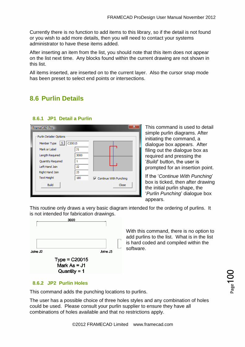
FRAMECAD ProDesign User Manual November 2012
©2012 FRAMECAD Limited www.framecad.com
Page100
Currently there is no function to add items to this library, so if the detail is not found or you wish to add more details, then you will need to contact your systems administrator to have these items added.
After inserting an item from the list, you should note that this item does not appear on the list next time. Any blocks found within the current drawing are not shown in
this list.
All items inserted, are inserted on to the current layer. Also the cursor snap mode has been preset to select end points or intersections.
8.6 Purlin Details
8.6.1 JP1 Detail a Purlin
This command is used to detail simple purlin diagrams. After initiating the command, a dialogue box appears. After filing out the dialogue box as required and pressing the ‘Build’ button, the user is
prompted for an insertion point.
If the ‘Continue With Punching’
box is ticked, then after drawing the initial purlin shape, the ‘Purlin Punching’ dialogue box
appears.
This routine only draws a very basic diagram intended for the ordering of purlins. It is not intended for fabrication drawings.
With this command, there is no option to add purlins to the list. What is in the list is hard coded and compiled within the software.
8.6.2 JP2 Purlin Holes
This command adds the punching locations to purlins.
The user has a possible choice of three holes styles and any combination of holes could be used. Please consult your purlin supplier to ensure they have all
combinations of holes available and that no restrictions apply.

FRAMECAD ProDesign User Manual November 2012
©2012 FRAMECAD Limited www.framecad.com
Page101
If ‘Auto Holes’ is ticked, holes will be inserted into the purlin from the start to the
finish at this exact spacing.
If it is not ticked, then the user will be prompted for each punch location.
Either way the software prompts the user for the starting location of the first hole.
If this command is used as a continuation of the ‘JP1’ command, then the user is not prompted for the purlin otherwise the user is required to select the purlin to add holes
to.
8.7 Downpipes
8.7.1 RLD Low Set Downpipes
This option allows the user to detail low set downpipes. Low set downpipes allows 1.5 lengths of length per downpipe. To use the command, just select a point where
you wish the downpipe to appear.
If desires a user may opt to press return to enter ‘RSET’ rather than picking a point, upon exit of ‘RSET’ the user will once again be prompted to select a point. A downpipe will be added to the drawing drawn on a layer called ‘qr_downpipe’.
8.7.2 RHD High Set Downpipes
This option allows the user to detail high set downpipes. High set downpipes allows 2.5 lengths of length per downpipe. To use the command, just select a point where you wish the downpipe to appear.
If desires a user may opt to press return to enter ‘RSET’ rather than picking a point, upon exit of ‘RSET’ the user will once again be prompted to select a point. A downpipe will be added to the drawing drawn on a layer called ‘qr_downpipe’.
8.7.3 RSP Spreader Downpipes
This option allows the user to detail spreader downpipes. Spreader downpipes allows 0.5 lengths of length per downpipe. To use the command, just select a point
where you wish the downpipe to appear.
If desires a user may opt to press return to enter ‘RSET’ rather than picking a point, upon exit of ‘RSET’ the user will once again be prompted to select a point. A downpipe will be added to the drawing drawn on a layer called ‘qr_downpipe’.
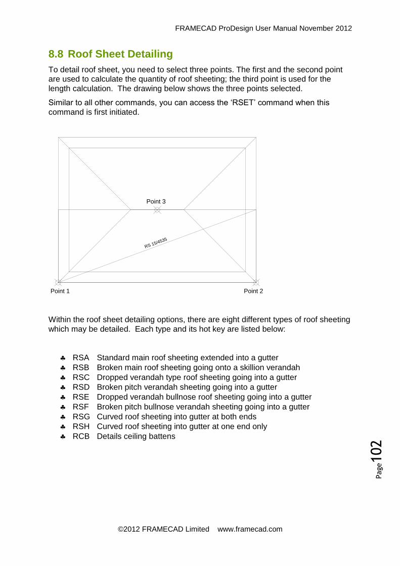
FRAMECAD ProDesign User Manual November 2012
©2012 FRAMECAD Limited www.framecad.com
Page102
8.8 Roof Sheet Detailing
To detail roof sheet, you need to select three points. The first and the second point are used to calculate the quantity of roof sheeting; the third point is used for the
length calculation. The drawing below shows the three points selected.
Similar to all other commands, you can access the ‘RSET’ command when this
command is first initiated.
Point 3
Point 1 Point 2
RS 15/4535
Within the roof sheet detailing options, there are eight different types of roof sheeting
which may be detailed. Each type and its hot key are listed below:
RSA Standard main roof sheeting extended into a gutter
RSB Broken main roof sheeting going onto a skillion verandah
RSC Dropped verandah type roof sheeting going into a gutter
RSD Broken pitch verandah sheeting going into a gutter
RSE Dropped verandah bullnose roof sheeting going into a gutter
RSF Broken pitch bullnose verandah sheeting going into a gutter
RSG Curved roof sheeting into gutter at both ends
RSH Curved roof sheeting into gutter at one end only
RCB Details ceiling battens

FRAMECAD ProDesign User Manual November 2012
©2012 FRAMECAD Limited www.framecad.com
Page103
RSD
RSBRSA
RSC
RSE
RSARSB
RSF
RSG
RSH
FRAMECAD ProDesign User Manual November 2012
©2012 FRAMECAD Limited www.framecad.com
Page104
8.9 Flashing
For the detailing of flashings and cappings, we have provided 12 different combinations. Select the type required. To detail, you are given the option of detail by ‘Entity’ or by ‘Points’. By ‘Entity’ means that the length of the item selected will be
takes as the length of the flashing (plus clearances etc).
The ‘Entity’ method allows you to select more than one entity at a time. The ‘Points’ method requires the operator to select the starting point and ending point of each flashing. When using this method the cursor is automatically set to select end points
or intersections. All flashings are drawn on the layer ‘qr_flashings’.
8.9.1 Flashing Commands
Items marked with the ‘р’ use the pitch component in their length calculations.
RFG – Fascia Gutter This details fascia and gutter simultaneously.
RFBр – Fascia Barge This details fascia and barge simultaneously.
RHOр – Hip Capping This details hip cappings only.
RRO – Ridge Capping This details ridge cappings only.
RVOр – Valley Gutters This details valley gutters only.
RFO – Fascia Only This details fascia only.
RGO – Gutter Only This details gutters only.
RBOр – Barge Only This details barge cappings only.
RDO – Dutch Flashing This details dutch flashings only.
RAOр – Apron Flashing This details apron flashings only.
RSO – Soaker Flashing This details soaker flashings only.
8.9.2 RCG Change Gutter Types
Quite often, you are requested to change the gutter type after completion of all detailing. Therefore this command has been provided to fulfil that function. To use this command, select the desired gutter entities then select a new gutter type from
the list.
There is no need to set the colours again as the colour settings are preserved. However you will need to redo all reports and onpage summaries.

FRAMECAD ProDesign User Manual November 2012
©2012 FRAMECAD Limited www.framecad.com
Page105
8.10 Soffits
8.10.1 REL Eave Soffit
This command is used to detail soffit linings to the eaves. Similar to all other commands, you can access the ‘RSET’ command when this command is first
initiated.
To use the command you need to select three points similar to the roof sheet
detailing functions. All detailed soffits are placed on the ‘qr_soffit’ layer.
The ‘Eave Soffit’ does not use any pitch component in its quantity calculations.
8.10.2 RBL Barge Soffit
This command is used to detail barge linings to the eaves. Similar to all other commands, you can access the ‘RSET’ command when this command is first
initiated.
To use the command you need to select three points similar to the roof sheet
detailing functions. All detailed soffits are placed on the ‘qr_soffit’ layer.
The ‘Barge Soffit’ uses the main roof pitch in its quantity calculations.
8.10.3 RVL Verandah Lining
This command is used to detail verandah linings to the eaves. Similar to all other commands, you can access the ‘RSET’ command when this command is first
initiated.
To use the command you need to select three points similar to the roof sheet
detailing functions. All detailed soffits are placed on the ‘qr_soffit’ layer.
The ‘Verandah Soffit’ uses the verandah roof pitch in its quantity calculations.
8.11 Reports
8.11.1 ROS Onsheet Summary
The ‘Onsheet Summary’ creates a summary showing the total quantity and the
length of the materials and their accessories. This summary is inserted onto the drawing sheet only.
The command gives the user the opportunity to make a selection of items or just do a global selection. A secondary prompt also given the user the opportunity to align the report box either ‘Left’ aligned or ‘Right’ aligned.

FRAMECAD ProDesign User Manual November 2012
©2012 FRAMECAD Limited www.framecad.com
Page106
When selecting a point for the report, the user is given the option to set some report
options. These should be set on an individual needs basis.
This summary is a relative low tech report, as it does not update automatically. If you wish to update it, then first you will need to use the cad ‘Erase’ command to
remove it.
8.11.2 ROT Onsheet Totals
The ‘Onsheet Totals’ creates a summary showing the total quantity for each item
found along with its accessories. This summary is inserted onto the drawing sheet
only.
The command gives the user the opportunity to make a selection of items, or just do a global selection. A secondary prompt also given the user the opportunity to align the report box either ‘Left’ aligned or ‘Right’ aligned.
When selecting a point for the report, the user is given the option set some report options, these should be set on an individual needs basis.
This summary is a relative low tech report, as it does not update automatically. If you wish to update it, then first you will need to use the cad ‘Erase’ command to
remove it.
8.11.3 RUR Materials Report
The ‘Material Usage Report’ operates from the detailed wall panels. It creates a
detailed list of components.
At the top of the report is a menu containing various options. Under the export item you can export the report to a text file or a CSV type file. The ‘CSV’ format can be
very useful as it will open up in ‘Excel’. You can also print the report.
8.11.4 RCNC CNC Output
This command works from the items detailed. It generates the required files needed to drive the roll formers. Most routines give the user the option to select the desired
items or return for a global selection.
Upon completion of this routine, the ‘CNC File’ is deposited in the ‘\My
Documents\CNC’ folder.
Each system basically has a different routine, but the software is indigent in this respect, so it uses the correct routine for each system. As each system is different, the file extension can vary from system to system, so to file out your file extension,
please contact your systems administrator.
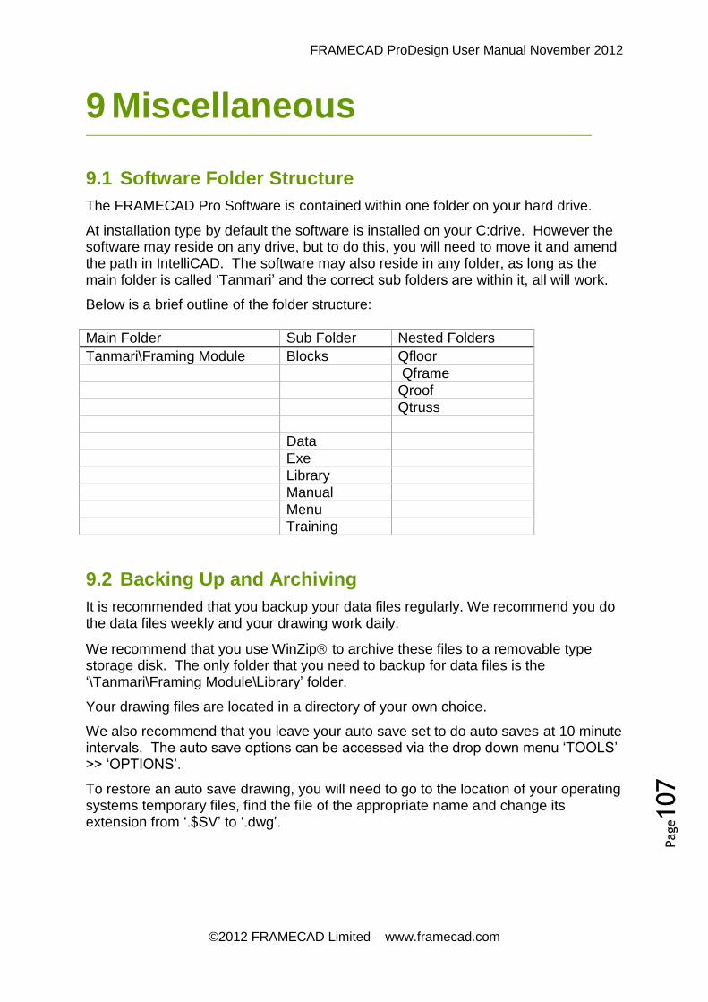
FRAMECAD ProDesign User Manual November 2012
©2012 FRAMECAD Limited www.framecad.com
Page107
9.1 Software Folder Structure
The FRAMECAD Pro Software is contained within one folder on your hard drive.
At installation type by default the software is installed on your C:drive. However the software may reside on any drive, but to do this, you will need to move it and amend the path in IntelliCAD. The software may also reside in any folder, as long as the main folder is called ‘Tanmari’ and the correct sub folders are within it, all will work.
Below is a brief outline of the folder structure:
Main Folder Sub Folder Nested Folders
Tanmari\Framing Module Blocks Qfloor
Qframe
Qroof
Qtruss
Data
Exe
Library
Manual
Menu
Training
9.2 Backing Up and Archiving
It is recommended that you backup your data files regularly. We recommend you do the data files weekly and your drawing work daily.
We recommend that you use WinZip to archive these files to a removable type storage disk. The only folder that you need to backup for data files is the ‘\Tanmari\Framing Module\Library’ folder.
Your drawing files are located in a directory of your own choice.
We also recommend that you leave your auto save set to do auto saves at 10 minute intervals. The auto save options can be accessed via the drop down menu ‘TOOLS’ >> ‘OPTIONS’.
To restore an auto save drawing, you will need to go to the location of your operating systems temporary files, find the file of the appropriate name and change its extension from ‘.$SV’ to ‘.dwg’.
9 Miscellaneous
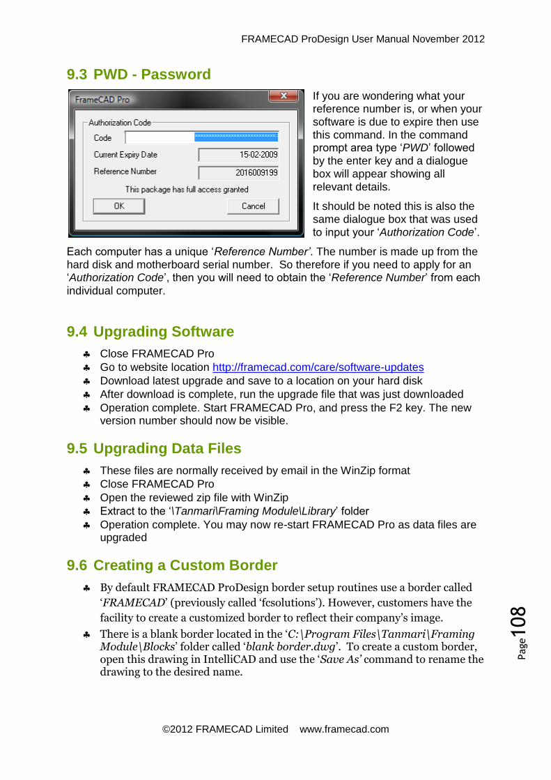
FRAMECAD ProDesign User Manual November 2012
©2012 FRAMECAD Limited www.framecad.com
Page108
9.3 PWD - Password
If you are wondering what your reference number is, or when your software is due to expire then use this command. In the command prompt area type ‘PWD’ followed
by the enter key and a dialogue box will appear showing all relevant details.
It should be noted this is also the same dialogue box that was used to input your ‘Authorization Code’.
Each computer has a unique ‘Reference Number’. The number is made up from the hard disk and motherboard serial number. So therefore if you need to apply for an ‘Authorization Code’, then you will need to obtain the ‘Reference Number’ from each
individual computer.
9.4 Upgrading Software
Close FRAMECAD Pro
Go to website location http://framecad.com/care/software-updates
Download latest upgrade and save to a location on your hard disk
After download is complete, run the upgrade file that was just downloaded
Operation complete. Start FRAMECAD Pro, and press the F2 key. The new version number should now be visible.
9.5 Upgrading Data Files
These files are normally received by email in the WinZip format
Close FRAMECAD Pro
Open the reviewed zip file with WinZip
Extract to the ‘\Tanmari\Framing Module\Library’ folder
Operation complete. You may now re-start FRAMECAD Pro as data files are upgraded
9.6 Creating a Custom Border
By default FRAMECAD ProDesign border setup routines use a border called
‘FRAMECAD’ (previously called ‘fcsolutions’). However, customers have the
facility to create a customized border to reflect their company’s image.
There is a blank border located in the ‘C:\Program Files\Tanmari\Framing Module\Blocks’ folder called ‘blank border.dwg’. To create a custom border, open this drawing in IntelliCAD and use the ‘Save As’ command to rename the drawing to the desired name.

FRAMECAD ProDesign User Manual November 2012
©2012 FRAMECAD Limited www.framecad.com
Page109
In the blank border, a space has been left where you may insert your company logo or any required text. You may alter or rearrange any text within the blank border as you see fit. Lines may be copied, moved or erased as required.
Please do not delete any of the attributes. These attributes are vital to the borders operation. Existing attributes may be moved or rearranged as required. If desired attributes visibility may be changed from visible to invisible.
When inserting company logo’s make sure they are in dwg format. Inserting bitmaps seldom works and is generally a waste of time. Also watch the size of the logo used. There is no point creating a custom border if the border winds up several megabytes in size. Whilst the border may look pretty the speed penalty taken will certainly overrule the border size.
Once you have created your custom border you must go to BSET and change
the border name to the same as which you have called your filename.
9.7 PRIA Print Layouts
This section only applies to those using IntelliCAD Version 5 onwards. This routine will print the entire layout drawing views or detailed drawing views to the current
printer.
Drawings are actually printed to a scale that fits the selected paper size. So on this basis it is actually the paper size that determines the scale.

FRAMECAD ProDesign User Manual November 2012
©2012 FRAMECAD Limited www.framecad.com
Page110
For the purposes of architectural or detailing work this is usually adequate. However if you do need to print to a precise scale, you will need
to use the IntelliCAD print command.
When the command is first initiated a dialogue box appears. Here you can manipulate printing in almost any way you wish.
‘Printer Name’. By pressing the ‘S’ button to the left of this field, you can select the printer that you wish to print with.
‘Number of Copies’. This field lets you set any number of copies you desire. When the drawings are printed, they are collated into groups.
‘Print Layouts’. If this field is ticked, then all alpha views, views named a, b, c etc, will be printed. Under normal circumstances this is used to print layout drawings. When printing, the software advanced from view a to view b to view c etc, and stops printing when no more sequenced views are found.
‘Print Details’. If this field is ticked, then all numeric views, views named 1, 2, 3 etc, will be printed. Under normal circumstances this is used to print the panel detail drawings. When printing, the software advanced from view 1 to view 2 to view 3 etc, and stops printing when no more sequenced views are found.
‘Select’. After pressing this button, the user is prompted to select the borders that will be printed. Only borders selected will be printed. This function works with both layout and detailed drawings. Before using this command, make sure your printer has been selected, as you will have no further option to change it after selecting the borders. If you do wish to cancel printing, try pressing the ‘ESC’ button on the keyboard. You may need to press this button repeatedly.
‘GO’. By pressing this button, all views of the selected type will be spool printed. Before using this command, make sure your printer has been selected, as you will have no further option to change it. If you do wish to cancel printing, try pressing the ‘ESC’ button on the keyboard. You may need to press this button repeatedly.
Print Manager
This section only applies to those using IntelliCAD Version 5 onwards. For more information on this item, please refer to the IntelliCAD help files.

FRAMECAD ProDesign User Manual November 2012
©2012 FRAMECAD Limited www.framecad.com
Page111
9.8 ResetMenu
Sometimes, for reasons unknown, the top dropdown menus need to be reset from time to time. That is the purpose of this function. In the command prompt area type ‘Resetmenu’ followed by the enter key and the menus will be reset.
So if you notice that your menu bar is incomplete, or dropdown items are incomplete, then try this ‘Resetmenu’ command. One should also note that each time an
upgrade is installed, the software will automatically reload the menu for you.
9.9 Resetting the Paths
- On the top menus select ‘Tools’ - On the top menus select ‘Options’ - On the ‘Options’ dialogue box select the ‘Paths/Files’ tab on the top. - In the drawings field the path should read
‘C:\Users\Username\Documents;C:\Program Files\Tanmari\IntelliCAD 6.6\;’
- In the menu field the path should read ‘C:\Program Files (x86)\Tanmari\IntelliCAD 6.6’
- Press ‘OK’ to close the dialogue box and save settings. - With these two paths set, FRAMECAD Pro should now load correctly.

FRAMECAD ProDesign User Manual November 2012
©2012 FRAMECAD Limited www.framecad.com
Page112
Below is a summary of the FRAMECAD ProDesign hot keys. There is no need to memorize
these keys as with repeated use that will come naturally. If you look at any of the drop down
menus at the top or the CAD screen you will notice that these hot keys are also listed beside
the command description.
10.1 Commands in Alphabetical Order
Command Description
ACNC Additional CNC Options
AD Aluminium Sliding Door
AR Square arch
AW Aluminium Windows
BSET Setup borders
BT Builds a single truss
C Copy
CA Calculator
CI Circle
CL Current layer
CRL Roof line wizard
CS Single cavity slider
CSD Double cavity slider
CT Codes lines as trusses
CTXT Replace text
D Dynamic test
DA Dimensions aligned
DD Attribute edit
DE Text Edit
DH Dimensions horizontally
DHH Dimensions walls only horizontally
DI Distance
DJH Dimensions joists only horizontally
10 Command Summary

FRAMECAD ProDesign User Manual November 2012
©2012 FRAMECAD Limited www.framecad.com
Page113
DJV Dimensions joists only vertically
DL Dimensions lengths only
DO Dimensions ordinate style
DT Main truss layout engine
DTH Dimensions trusses only horizontally
DTV Dimensions trusses only vertically
DV Dimensions vertically
DVV Dimensions walls only vertically
E Erase
EA Erase a Layer
EBR Brick Fit Ext. Corner
ED Single door
EL Explode
EP Cursor to end point
ETG Erased truss layouts
EX Extend
F Fillet
F1 Help
F2 Prompt history
F3 End snap
F4 Tablet
F5 Isoplane
F6 Coordinate
F7 Grid
F8 Orthogonal
F9 Snap
FL Freeze a Layer
FO Frame offset
FS Single FOW (Face of Wall Sliding)
FSD Double FOW (Face of Wall Sliding)
FTXT find text
I Insert

FRAMECAD ProDesign User Manual November 2012
©2012 FRAMECAD Limited www.framecad.com
Page114
IBM Insert bubble mark
IBR Brick Fit Int. Door
ICD check dimensions
IIM Insert item mark
IL Isolate layer
ILT Insert leader text
IP Inherit properties
J Join Line
J3D Make Floor 3D
JAD Add Drawing Detail
JAM Add a Member
JAP Add Part Details
JAS Add Sectional Properties
JBP Create Bracket Plan
JCNC Create Joist CNC File
JD Joist detail
JDF Floor Sheeting
JEG Erase guides
JEX expand shrink members
JFJ Find Joist
JIC Integrity check
JID Insert Connection Detail
JIM Insert a Member
JIS Insert Service Line
JJC Joist Single Cut
JJD Auto floor detailer
JJM Joist multiple cut
JLA Joist label
JLI Lists joist properties
JLR Layout report
JOB On page bracket summary
JOF On page sheet summary
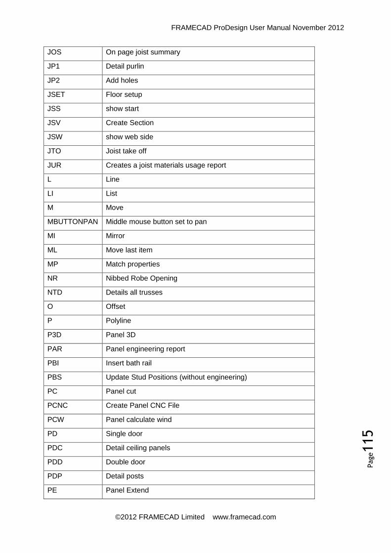
FRAMECAD ProDesign User Manual November 2012
©2012 FRAMECAD Limited www.framecad.com
Page115
JOS On page joist summary
JP1 Detail purlin
JP2 Add holes
JSET Floor setup
JSS show start
JSV Create Section
JSW show web side
JTO Joist take off
JUR Creates a joist materials usage report
L Line
LI List
M Move
MBUTTONPAN Middle mouse button set to pan
MI Mirror
ML Move last item
MP Match properties
NR Nibbed Robe Opening
NTD Details all trusses
O Offset
P Polyline
P3D Panel 3D
PAR Panel engineering report
PBI Insert bath rail
PBS Update Stud Positions (without engineering)
PC Panel cut
PCNC Create Panel CNC File
PCW Panel calculate wind
PD Single door
PDC Detail ceiling panels
PDD Double door
PDP Detail posts
PE Panel Extend

FRAMECAD ProDesign User Manual November 2012
©2012 FRAMECAD Limited www.framecad.com
Page116
PEG Erase guides
PF Panel filet
PFF Find A Panel
PHH Calc Head Location
PIB Insert brace
PIC Check integrity
PID Insert Detail
PJ Panel join
PL Panel Lengthen
PLA Panel Label
PLI List A Member
PM Panel miter
PMI Mirror panel layout
PO Polygon
POB Beam summary
POD On page design summary
POO Opening summary
POP Post summary
POS On page summary
PPD Panel Detailer
PR1 Single Robe Door
PR2 Double Robe Door
PR3 Triple Robe Door
PRA Rake to angle
PRH Rake to height
PRP Rake to plane
PS Panel square
PS2 Double Sliding Door
PS3 Triple Sliding Door
PS4 Four Sliding Door
PSA Stud array
PSC Copy Array Studs

FRAMECAD ProDesign User Manual November 2012
©2012 FRAMECAD Limited www.framecad.com
Page117
PSN Special nog
PST Panel stacking
PT Panel Trim
PTF Panel Trace frame
PU cleans out library to make file smaller
PUJ Panel unlock
PVC Visual Controls
PX Panels Crossing
QGL Grid lines
QS Quick Save
QSET Frame settings
QST Quick Steel
QT Quick text insertions
R Redraw the screen
R3D Model 3D Roof
RAD Auto Roof Detail
RAO Apron flashing
RBL Barge soffits
RBO Barge only
RCB Ceiling Battens
RCG Change gutter type
RCL Create Roof Lines
RCNC CNC
RCO Set Colours
RCR Copy a Roof Outline
RDO Dutch flashing
RE Reset cursor snap type
REF Reference Point
REL Eave soffits
REV Revision marking and updating feature
RFB Fascia barge
RFG Fascia gutter

FRAMECAD ProDesign User Manual November 2012
©2012 FRAMECAD Limited www.framecad.com
Page118
RFO Fascia only
RGO Gutter only
RHD High Set Downpipe
RHO Hip capping
RID Insert detail
RLD Low Set Downpipe
RLI List an Item
RO Rotate
ROS On sheet summary
ROT On sheet totals
RRA Get Roof Area
RRO Ridge capping
RRS Create Roof Shapes
RSA Standard Main Sheeting
RSB Broken Pitch Main Sheeting
RSC Standard Verandah Sheeting
RSD Broken Pitch Verandah Sheeting
RSE Standard Bullnose
RSET Qroof Setup
RSF Broken Pitch Bullnose
RSG Double End Curved
RSH Single End Curved
RSO Soaker flashing
RSP Spreader Pipes
RUR Materials Report
RVL Verandah linings
RVO Valley capping
S Scale
SE Select layer
SL Show Layers
SM Section mark
SN Set snap angle to 45

FRAMECAD ProDesign User Manual November 2012
©2012 FRAMECAD Limited www.framecad.com
Page119
SNAPANG Set snap angle to specified angle
ST Stretch
STD Details selected trusses
STH Converts a square end to a hex end
STL Split a truss layout
SW Turn ON / OFF working layer
SWA Add to working layer
T Trim
T3D Create 3D view
TA Thaw All Layers
TAD Add / edit detail drawing
TAL Analysis with report
TAN Analysis without report
TAP Adds packers
TAR Analysis with report
TAS Adds support points
TAW Adds webs
TBB Bottom Chord Brace
TBM Fully boxes a member
TBP Partially boxes a member
TBR Breaks a truss
TBT Builds a single truss
TCB Construction Brace
TCE Rebuilds eaves
TCNC Create Truss CNC File
TCT Codes lines as trusses
TCW Calculate wind
TD Timber Sliding Door
TDT Main truss layout engine
TES Truss engineering status
TEW Eases selected webs
TFT Find a truss on a layout

FRAMECAD ProDesign User Manual November 2012
©2012 FRAMECAD Limited www.framecad.com
Page120
TH Code as a hanging beam
TIC Truss integrity check
TID Truss insert detail
TJD Inserts joint details
TL Label roof trusses
TLA Label roof trusses
TLI Lists a truss
TLJ List a truss joint
TLR Truss Layout Report
TMH Re-calculates chord to chord connection holes
TMI Mirrors selected webs
TMW Mirror Webs
TOA On page accessories list
TOD On page design summary
TON On Sheet Hip Locations
TOR Truss Optimization Summary
TOS On page truss summary
TOV On page verandah rafter summary
TPL Adds point loads
TR Code as roof line
TRB Add roof bracing to layout
TRL Amend truss RL (3D height)
TS Code as support line
TSC Splices a truss chord
TSET Main truss settings
TSF Shows truss failures
TTC Cuts a single truss
TTM Cuts multiple trusses
TTO Main truss takeoff
TUA Updates a multiple cutting list
TUP Truss uplift plan

FRAMECAD ProDesign User Manual November 2012
©2012 FRAMECAD Limited www.framecad.com
Page121
TUR Creates a truss materials usage report
TUS Updates a single cutting list
TVC Truss visual controls
TVS Splits a truss Horizontal
TW Timber Window
TWH Re-calculates chord to web connection holes
TWR Add Web Restraint
TXL Creates a truss materials usage export to Excel
UD User Defined Door
ULE Run of Engaged Piers
ULI Run of Isolated Piers
URU Rough in Under floor
USE Single Engaged Pier
USI Single Isolated Pier
USP Single Support Post
UW User Defined Windows
V Restore a view
VM Make a view
VR Return to view 1
VV Advance through views
X Zoom previous
XD List extended data
Z Zoom
ZE Zoom Extents
ZOOMFACTOR Changes the mouse scroll speed

FRAMECAD ProDesign User Manual November 2012
©2012 FRAMECAD Limited www.framecad.com
Page122
11.1 Software Fails to Load
FRAMECAD ProDesign Software modules are loaded via the FRAMECAD Pro shortcut ‘ file
which is located in the \Tanmari folder. This file loads the ‘icad.exe’ file which in turn loads
the rest of the FRAMECAD ProDesign modules. Should this file ever be overwritten with
another ‘icad.exe’ file then the FRAMECAD ProDesign Software package will fail to load. If
it appears that the software has failed to load, the easiest way to check is to press the ‘F2’
key immediately after FRAMECAD ProDesign has been started. Your screen should look
something like the text below. If it does not, then you can be relatively sure that the
‘icad.exe’ file is not the FRAMECAD ProDesign version, or is corrupted or is missing
altogether. But if you screen does look similar to the screen above, then the software has
loaded and the ‘icad.exe’ file is not your problem.
11.2 Some Commands Do Not Work
Most of the FRAMECAD ProDesign command are two or three digit commands, and most of
the standard IntelliCAD alias commands are also two or three digit commands, however
some of the FRAMECAD ProDesign commands clash with some of the more obscure
IntelliCAD commands. For this reason when the software was loaded, the FRAMECAD
ProDesign alias commands were loaded.
To check if the alias commands are correct, type ‘TR’. If the trim command is activated
instead of the ‘Code as Roof Line’ command, then the Alias commands need to be reset. To
reset the Alias commands please refer to ‘Procedure One’ outlined below.
This problem can occur for several different reasons; one cause would be logging on using a
different name, loading an IntelliCAD only upgrade, or accidentally resetting the alias
command. At installation time this problem occurs if you do not have administrator access.
11 Some Common Problems
FRAMECAD Pro Licence Expires on 30-09-2010...
FRAMECAD Pro Software Version 11.591...
FRAMECAD Pro Roofing Module Loaded...
FRAMECAD Pro Truss Module Loaded...
FRAMECAD Pro Tools Module Loaded...
FRAMECAD Pro Floor Module Loaded...
FRAMECAD Pro Wall Module Loaded...FRAMECAD ProDesign Software Tools Module Loaded...
FRAMECAD ProDesign Software Floor Module Loaded...
FRAMECAD ProDesign Software Wall Module Loaded...

FRAMECAD ProDesign User Manual November 2012
©2012 FRAMECAD Limited www.framecad.com
Page123
11.3 The Menu is Missing
FRAMECAD ProDesign Software uses a menu with many more options than the standard
IntelliCAD menu. This menu is supplied with and installed with the software. It is also
included within most of the FRAMECAD ProDesign upgrades.
From time to time the menu seems to get screwed up for any of several different reasons.
To resolve this problem, a special command has been provided called ‘RESETMENU’. To
use the command, start IntelliCAD and type ‘RESETMENU’.
Should the ‘RESETMENU’ command fail to work please refer to ‘Procedure Three’ outlined
below.
11.4 Correction Procedures
11.4.1 Procedure 1 – Resetting the Alias Commands
Start IntelliCAD
On the top menus select ‘Tools’ => ‘Customize’
On the ‘Customize’ dialogue box select the ‘Aliases’ tab on the top
Next press the ‘Import’ button
In the ‘File Name’ box type ‘C:\Program Files\Tanmari\Framing Module\Menu\Icad.ica’
Make sure the ‘Append to existing’ is not ticked
Press ‘Open’ to close the alias box
Press ‘Close’ to close the customise box
11.4.2 Procedure 2 – Resetting the Paths
Start IntelliCAD
On the top menus select ‘Tools’ => ‘Options’
On the ‘Options’ dialogue box select the ‘Paths/Files’ tab on the top.
In the drawings field the path should read ‘C:\Users\Username\Documents;C:\Program Files\Tanmari\IntelliCAD 6.6\’
In the menu field the path should read ‘C:\Program Files\Tanmari\IntelliCAD 6.6’ Press ‘OK’ to close the dialogue box and save settings.
With these two paths set, FRAMECAD ProDesign should now load correctly
11.4.3 Procedure 3 – Resetting the Menu
Start IntelliCAD
On the top menus select ‘Tools’ => ‘Customize’
On the ‘Customize’ dialogue box select the ‘Menus’ tab on the top
Next press the ‘Import’ button
Make sure the ‘Append to current menu’ is not ticked
In the ‘File Name’ box type ‘C:\Tanmari\Framing Module\Menu\Icad.icm’ or change the file type dropdown to ‘IntelliCAD Menu File (icm)’ and navigate to the above location.
Press ‘Open’ to close the menu box
Press ‘Close’ to close the customise box

FRAMECAD ProDesign User Manual November 2012
©2012 FRAMECAD Limited www.framecad.com
Page124
12.1 Wall Panel Engineering
Engineered items are designed when ‘PAR’, ‘PCW’ and ‘PPD’ commands are initiated on the wall panel layouts, or when the user uses the ‘Update Engineering’ feature. The software finds the imposed loads from the roof truss and floor framing layouts and converts these loads to uniformly distributed loads. The horizontal wind loads are also calculated according to the usage of the wall panels, external walls use external wind coefficients and internal walls use internal wind coefficients. Through these calculations and checks the top plates, window heads, wind bracing, stud density and stud spacing’s are determined.
12.1.1 Common Notations
G = Gravity load Q1 = Roof or floor live load (maximum) Q2 = Roof live load Q3 = Floor live load Q4 = Roof plus floor live load P1 = 1.1kN point load P2 = 0.7kN impact load P3 = 1.0kN point load Wu = Wind upward force = quCpu Wd = Wind downward force = quCpd Wh = Wind horizontal force = quCph Cpu = Nett pressure coefficient Cpd = Nett pressure coefficient Cph = Nett pressure coefficient qu = Reference pressure
= 0.0006(Vs)2
= 0.000613(Vs)2 (British Only)
Vs = Design wind speed (minimum 30m/s) S = Snow load vertically
L = Length of stud being designed ks = Load redistribution factor
s = Maximum spacing between noggins n = Number of noggins
= Deflection
12.1.2 Design Wind Loads
The wind speed expressed is the ultimate design wind speed expressed in metres per
second for metric users and miles per hour for imperial users. From this wind speed, the
free stream gust wind pressures are derived. If the wind speed has a trailing ‘C’ then
cyclonic conditions are assumed.
12 Engineering Statements

FRAMECAD ProDesign User Manual November 2012
©2012 FRAMECAD Limited www.framecad.com
Page125
Nett Pressure Coefficients
Non Cyclonic
Cyclonic
Cpu Wind upwards
(Roof)
1.10 (0.9 + 0.2)
1.60 (0.9 + 0.7)
Cpd Wind Downwards
(Roof)
0.70 (0.4 + 0.3)
1.05 (0.4 + 0.65)
Cph Wind Horizontal 1.00 (0.7 + 0.3)
1.35 (0.7 + 0.65)
12.1.3 Stud Design
The ‘X’ direction lengths of the studs are calculated to be the maximum spacing between the noggins and the ‘Z’ direction length is the overall length of the stud between the top and bottom plates. Where a restraint height has been set in ‘PLI’, the height in the ‘Z’ direction is assumed to be this value. Design checks are carried to the following design standards for the listed load combinations. Stud capacities are calculated to the design standards using effective section properties calculated using the AISI-AS/NZS4600 method. For AS/NZS 4600:2005
Load Combinations LC1 1.2G + 1.5Q1 Strength check LC2 1.2G + 0.4Q2 + 1.5S Strength check
LC3 1.2G + 1.5Q3 + 1.5S Strength check LC4 1.2G + 1.5P1 Strength check LC51 1.2G + 0.4Q3 + Wd + Wh Strength check LC61 0.9G + Wu + Wh Strength check LC7 0.6Wh Serviceability check
LC8 P2 Serviceability check For SASFA:2007
Load Combinations LC1 1.2G + 1.6Q4 Strength check LC2 1.2G + 0.4Q2 + 1.6S Strength check
LC3 1.2G + 1.6Q3 + 1.6S Strength check LC4 1.2G + 1.6P3 Strength check LC51 1.2G + 1.3Wd + 1.3Wh Strength check LC61 0.9G + 1.3Wu + 1.3Wh Strength check LC7 0.6Wh Serviceability check
LC8 P2 Serviceability check

FRAMECAD ProDesign User Manual November 2012
©2012 FRAMECAD Limited www.framecad.com
Page126
For AISI S100-2007 LRFD
Load Combinations LC1 1.2G + 1.6Q1 Strength check LC2 1.2G + 0.5Q2 + 1.6S Strength check
LC3 1.2G + 1.6Q3 + 0.5S Strength check LC4 1.2G + 1.6P1 Strength check LC51 1.2G + 1.6Q3 + 1.6Wh Strength check LC61 0.9G + 1.6Wu + 1.6Wh Strength check LC7 1.0Wh Serviceability check
LC8 P2 Serviceability check For CSA S136-2007
Load Combinations LC1 1.25G + 1.5Q1 Strength check LC2 1.25G + 0.5Q2 + 1.5S Strength check
LC3 1.25G + 1.5Q3 + 1.5S Strength check LC4 1.25G + 1.5P1 Strength check LC51 1.25G + 0.5Q3 + 1.4Wh Strength check LC61 1.0G + 1.4Wu + 1.4Wh Strength check LC7 0.6Wh Serviceability check
LC8 P2 Serviceability check For BS5950-5:1998
Load Combinations LC1 1.4G + 1.6Q1 Strength check LC2 1.4G + 1.6Q2 + 1.6S Strength check
LC3 1.4G + 1.6Q3 + 1.6S Strength check LC4 1.4G + 1.6P1 Strength check LC52 1.2G + 1.6Q3+ 1.4Wd+ 1.4Wh Strength check LC62 G + 1.4Wu + 1.4Wh Strength check LC7 0.6Wh Serviceability check
LC8 P2 Serviceability check
For EN 1993-1-3:2006
Load Combinations LC1 1.35G + 1.5Q4 Strength check LC2 1.35G + 1.05Q2 + 1.5S Strength check
LC3 1.35G + 1.5Q3 + 0.75S Strength check LC4 1.35G + 1.5P1 Strength check LC53 1.35G + 1.05Q3 + 1.5*Wd
+ 1.5*Wh+ 0.75S Strength check LC63 1.0G + 1.5*Wu + 1.5*Wh Strength check LC7 1.0Wh Serviceability check
LC8 P2 Serviceability check * 1.75 Factor when ‘C’ (cyclone) wind specified.
For GB 5009-2001
Load Combinations LC1 1.2G + 1.4Q4 Strength check LC2 1.2G + 1.00Q2 + 1.4S Strength check
LC3 1.2G + 1.4Q3 + 1.0S Strength check LC4 1.2G + 1.4P1 Strength check LC53 1.2G + 0.85Q3 + 0.85Wd
+ 1.4Wh + 1.0S Strength check LC63 1.0G + 0.85Wu + 1.4Wh Strength check

FRAMECAD ProDesign User Manual November 2012
©2012 FRAMECAD Limited www.framecad.com
Page127
LC7 1.0Wh Serviceability check LC8 P2 Serviceability check
1 Denotes an effective length k factor of 0.8 for studs in ‘Z’ direction. 2 Denotes an effective length k factor of 0.85 for studs in ‘Z’ direction. 3 Denotes an effective length k factor of 0.7 for studs in ‘Z’ direction.
For serviceability limits For LC7 L / 150mm or 20mm
For LC8 L / 200mm or 12mm
For LC8 the point load is applied at the mid height of the stud and is considered to be distributed over a panel length of 1m. For connection capacity of the stud to the plate, load combination LC6 has been used for this check. For all cases the connection is only checked for resistance to uplift as it is assumed full bearing is available within the stud to plate connection.
12.1.4 PAR Load Report
The ‘PAR’ command generates a load report. This report shows the calculated load at the top and bottom plate of each wall panel. All these loads are not factored. This report also shows the upward and downward reaction for each wall panel. The reactions are factored. The reactions are factored from the load combinations listed below. The downward reaction is the maximum value for all load combinations evaluated. For AS/NZS 4600:2005
Load Combinations LC1 1.2G + 1.5Q1 Downwards LC2 1.2G + 0.4Q2 + 1.5S Downwards
LC3 1.2G + 1.5Q3 + 1.5S Downwards LC5 1.2G + 0.4Q3 + Wd Downwards
LC6 0.9G + Wu Upwards For SASFA:2007
Load Combinations LC1 1.2G + 1.6Q1 Downwards LC2 1.2G + 0.4Q2 + 1.6S Downwards
LC3 1.2G + 1.6Q3 + 1.6S Downwards LC5 1.2G + 1.3Wd Downwards LC6 0.9G + 1.3Wu Upwards
For AISI S100-2007 LRFD
Load Combinations LC1 1.2G + 1.6Q1 Downwards LC2 1.2G + 0.5Q2 + 1.6S Downwards
LC3 1.2G + 1.6Q3 + 0.5S Downwards LC5 1.2G + 1.6Q3 + 1.6Wh Downwards LC6 0.9G + 1.6Wu + 1.6Wh Upwards

FRAMECAD ProDesign User Manual November 2012
©2012 FRAMECAD Limited www.framecad.com
Page128
For CSA S136-2007
Load Combinations LC1 1.25G + 1.5Q1 Downwards LC2 1.25G + 0.5Q2 + 1.5S Downwards
LC3 1.25G + 1.5Q3 + 1.5S Downwards LC5 1.25G + 0.5Q3 + 1.4Wh Downwards LC6 1.0G + 1.4Wu + 1.4Wh Upwards
For BS5950-5:1998
Load Combinations LC1 1.4G + 1.6Q1 Downwards LC2 1.4G + 1.6Q2 + 1.6S Downwards
LC3 1.4G + 1.6Q3 + 1.6S Downwards LC5 1.2G + 1.6Q3 + 1.4Wd Downwards LC6 G + 1.4Wu Upwards
For EN 1993-1-3:2006
Load Combinations LC1 1.35G + 1.5Q4 Downwards LC2 1.35G + 1.05Q2 + 1.5S Downwards
LC3 1.35G + 1.5Q3 + 0.75S Downwards LC3 1.35G + 1.5Q3 + 0.75S Downwards LC5 1.35G + 1.05Q3 + 1.5*Wd
+ 1.5*Wh+ 0.75S Downwards LC6 1.0G + 1.5*Wu + 1.5*Wh Upwards
* 1.75 Factor when ‘C’ (cyclone) wind specified. For GB 5009-2001
Load Combinations LC1 1.2G + 1.4Q4 Downwards LC2 1.2G + 1.00Q2 + 1.4S Downwards
LC3 1.2G + 1.4Q3 + 1.0S Downwards LC5 1.2G + 0.85Q3 + 0.85Wd
+ 1.4Wh + 1.0S Downwards LC6 1.0G + 0.85Wu + 1.4Wh Upwards

FRAMECAD ProDesign User Manual November 2012
©2012 FRAMECAD Limited www.framecad.com
Page129
12.2 Roof Truss Engineering
12.2.1 Preface
This document applies only the 2007 edition of FrameCAD Pro Software. The software’s engineering modules are operated purely from first principals; this means that all sectional properties and section capacities are calculated from scratch each time in real time. This document gives a basic outline of the calculations performed and methods used.
Cold Formed Steel Design requires the extensive use of effective sectional properties at varying stress level, plus the section capacities are a variable against the effective lengths of the material, because of this requirement it is not possible to give worked examples as each sample would run into many hundreds of pages.
A list of sections that are covered by this software is provided in the following figure.
Available Sections

FRAMECAD ProDesign User Manual November 2012
©2012 FRAMECAD Limited www.framecad.com
Page130
12.2.2 Principles of Operation
The method of analysis is via a 2D plane frame analysis using the displacement method with skyline matrix technology used to solve the equilibrium. The software takes the truss or rafter from the screen and reduces it to a single line drawing using the centroid of each member as the reference points. Apparent intersections are created thus creating node points with connecting lines. Each line is then subdivided into four more points; this enables us to do far more accurate bending and deflection
calculations.
Full sectional properties are calculated from the shape information stored. These full properties also take into account the radii of all corners. The warping constant and St Venants torsion constant are also calculated totally from first principles mostly
using matrix methods or methods of integration.
For each load case, the software calculates the forces imposed on each node and element within the truss. Also calculated are the effective sectional properties for both members under uniform compression and members under stress gradient. These effective sectional properties vary with the imposed load and length of each member, therefore the length of the member is taken to be the distance between the major node points.
On the completion of the analysis, the overall truss is checked for serviceability deflections and each member is checked for compliance with the code. The screwed, riveted or bolted joints are all designed by the software based on the largest terminating load at that point. Whilst the software designs the required fasteners at each joint, it does not do any checks to ensure that the quantity of
fasteners will fit within the allowed space. This may be addressed in future versions.

FRAMECAD ProDesign User Manual November 2012
©2012 FRAMECAD Limited www.framecad.com
Page131
12.2.2.1 Units of Measure
The software is not flexible with the units of measure. Units of measure used are listed below.
Abbreviation Report Type Unit of Measure
Metric Imperial
Location coordinates Node inputs Nominal units
Lengths and distances Various mm
Applied Point Loads Node inputs kN
Applied moments Node inputs N/m
Applied distributed loads Node inputs kpa/m
Yield/Tensile strength Section Data mpa
Moment of Inertia Sectional Properties mm4
Torsion constants Sectional Properties mpa
Warping constant Sectional Properties mpa
Rotation Node Results Degrees
Reactions Node Results N
Joint loads and capacities Node Results N
Axial forces Member Results N
Bending moments Member Results Nmm
Shear force Member Results N
Compression capacity Member Capacities N
Bending capacity Member Capacities Nmm
Shear capacity Member Capacities N
Effective area Member Capacities mm2
Section modulus Member Capacities mm3
Bearing Capacity Member Capacities N
Various Code Compliance Percentage %
12.2.2.2 Common Notations
Ag = gross area of section An = nett area of section lx = effective length in X axis ly = effective length in Y axis Ix = second moment of inertia about X axis Iy = second moment of inertia about Y axis Zx = section modulus about X axis Zy = section modulus about Y axis rx = radius of gyration about X axis ry = radius of gyration about Y axis xo = distance from X centroid to X shear centre yo = distance from Y centroid to Y shear centre ro1 = polar radius of gyration J = torsional constant Iw = warping constant E = Young’s modulus of elasticity 200000 G = shear modulus 80000 df = screw diameter tw = material thickness fy = material yield strength fu = material ultimate design strength

FRAMECAD ProDesign User Manual November 2012
©2012 FRAMECAD Limited www.framecad.com
Page132
12.2.3 Load Combinations
Load combinations are a regional or location base item and not directly coupled to the actual design code. The load combinations used for each code option as listed in the following sections.
In addition to uniform load cases, each member is checked for strength and stability by applying a point load of 1.1kN mid span of each major segment. This check is applied to members where the length of the major segment if greater than five time the height of the section. Load redistribution factors (ks) are applied to this point load.
ks = 0.2log10(10L-3/ ns-3) + 0.75 0.2 ≤ ks ≤ 1.0 Where
ks = load redistribution factor L = major segment length of member being designed s = spacing of crossing members n = number of crossings
12.2.4 Wind Loads
The wind speed expressed is the ultimate design wind speed expressed in m/s for metric users and mph for imperial users. From this wind speed, the free stream gust wind pressures are derived. If the wind speed has a trailing ‘C’ then cyclonic conditions are assumed.
Vu = ultimate design wind speed
Vs = serviceability wind speed = 0.4017Vu
qu = ultimate wind pressure = 0.0006(Vu)2
qs = serviceability wind pressures = 0.0006(Vs)2
For wind loads upwards the external pressure coefficient is set at 0.90. with the internal pressure coefficients preset at 0.20, for cyclonic conditions the internal pressure coefficient is set at 0.70.
For wind loads downwards the external pressure coefficient is set at 0.40, with the internal pressure coefficients preset at 0.30, for cyclonic conditions the internal pressure coefficient is set at 0.65.
For wind loads left to right the external pressure coefficient is set at 1.00, with the internal pressure coefficients preset at zero.
For serviceability wind loads downwards the external pressure coefficient is set at 0.90. with the internal pressure coefficients preset at 0.20, for cyclonic conditions the internal pressure coefficient remains set at 0.20.
For serviceability wind loads upwards the external pressure coefficient is set at 0.40. with the internal pressure coefficients preset at 0.30, for cyclonic conditions the internal pressure coefficient remains set at 0.30.
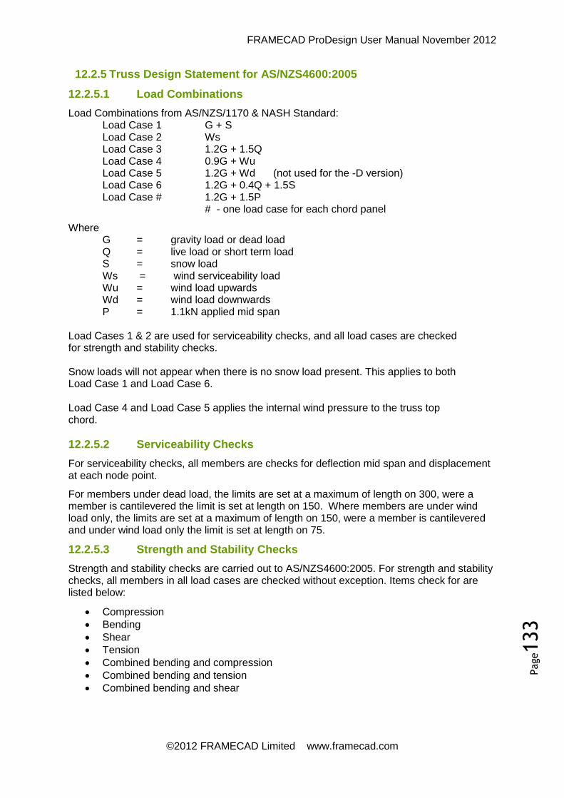
FRAMECAD ProDesign User Manual November 2012
©2012 FRAMECAD Limited www.framecad.com
Page133
12.2.5 Truss Design Statement for AS/NZS4600:2005
12.2.5.1 Load Combinations
Load Combinations from AS/NZS/1170 & NASH Standard: Load Case 1 G + S Load Case 2 Ws Load Case 3 1.2G + 1.5Q Load Case 4 0.9G + Wu Load Case 5 1.2G + Wd (not used for the -D version) Load Case 6 1.2G + 0.4Q + 1.5S Load Case # 1.2G + 1.5P
# - one load case for each chord panel
Where G = gravity load or dead load Q = live load or short term load S = snow load Ws = wind serviceability load Wu = wind load upwards Wd = wind load downwards P = 1.1kN applied mid span
Load Cases 1 & 2 are used for serviceability checks, and all load cases are checked for strength and stability checks. Snow loads will not appear when there is no snow load present. This applies to both Load Case 1 and Load Case 6. Load Case 4 and Load Case 5 applies the internal wind pressure to the truss top chord.
12.2.5.2 Serviceability Checks
For serviceability checks, all members are checks for deflection mid span and displacement at each node point.
For members under dead load, the limits are set at a maximum of length on 300, were a member is cantilevered the limit is set at length on 150. Where members are under wind load only, the limits are set at a maximum of length on 150, were a member is cantilevered and under wind load only the limit is set at length on 75.
12.2.5.3 Strength and Stability Checks
Strength and stability checks are carried out to AS/NZS4600:2005. For strength and stability checks, all members in all load cases are checked without exception. Items check for are listed below:
Compression
Bending
Shear
Tension
Combined bending and compression
Combined bending and tension
Combined bending and shear

FRAMECAD ProDesign User Manual November 2012
©2012 FRAMECAD Limited www.framecad.com
Page134
12.2.6 Truss Design Statement for SASFA Code 2007
12.2.6.1 Load Combinations
Load Combinations from SASFA Code: Load Case 1 1.1G + 1.1S Load Case 2 0.6W Load Case 3 1.2G + 1.6Q Load Case 4 0.9G + 1.3Wu Load Case 5 1.2G + 1.3Wd Load Case 6 1.2G + 0.4Q + 1.6S Load Case # 1.2G + 1.6P
# - one load case for each chord panel
Where G = gravity load or dead load Q = live load or short term load S = snow load Ws = wind serviceability load Wu = wind load upwards Wd = wind load downwards P = 1.1kN applied mid span
Load Cases 1 & 2 are used for serviceability checks, and all load cases are checked for strength and stability checks. Snow loads will not appear when there is no snow load present. This applies to both Load Case 1 and Load Case 6. Load Case 4 and Load Case 5 applies the internal wind pressure to the truss top chord.
12.2.6.2 Serviceability Checks
For serviceability checks, all members are checks for deflection mid span and displacement at each node point.
For members under dead load, the limits are set at a maximum of length on 300, were a member is cantilevered the limit is set at length on 150. Where members are under wind load only, the limits are set at a maximum of length on 150, were a member is cantilevered and under wind load only the limit is set at length on 75.
12.2.6.3 Strength and Stability Checks
Strength and stability checks are carried out to AS/NZS4600:2005. For strength and stability checks, all members in all load cases are checked without exception. Items check for are listed below:
Compression
Bending
Shear
Tension
Combined bending and compression
Combined bending and tension
Combined bending and shear

FRAMECAD ProDesign User Manual November 2012
©2012 FRAMECAD Limited www.framecad.com
Page135
12.2.7 Truss Design Statement for AISI S100-2007 LRFD
Load & Resistance Factor Design (LRFD)
12.2.7.1 Load Combinations
Load Combinations from IBC2009: Load Case1 G+S Load Case 2 Q Load Case 3 Wu Load Case 4 1.2G + 1.6Q + 0.5S Load Case 5 1.2G + 1.6Wu Load Case 6 1.2G + 0.5Q + 1.6S Load Case # 1.2G + 1.6P
# - one load case for each chord panel
Where G = gravity load or dead load Q = live load or short term load S = snow load Wu = wind load upwards Wd = wind load downwards P = 1.1kN applied mid span
Load Cases 1, 2 & 3 are used for serviceability checks, and all load cases are checked for strength and stability checks. Snow loads will not appear when there is no snow load present. This applies to both Load Case 1, 4 and Load Case 6. Load Case 5 applies the internal wind pressure to the truss top chord.
12.2.7.2 Serviceability Checks
For serviceability checks, all members are checks for deflection mid span and displacement at each node point.
For members under dead load, the limits are set at a maximum of length on 300, were a member is cantilevered the limit is set at length on 150. Where members are under wind load only, the limits are set at a maximum of length on 150, were a member is cantilevered and under wind load only the limit is set at length on 75.
12.2.7.3 Strength and Stability Checks
Strength and stability checks are carried out to AISI S100-2007 LRFD. For strength and stability checks, all members in all load cases are checked without exception. Items check for are listed below:
Compression
Bending
Shear
Tension
Combined bending and compression
Combined bending and tension
Combined bending and shear

FRAMECAD ProDesign User Manual November 2012
©2012 FRAMECAD Limited www.framecad.com
Page136
12.2.8 Truss Design Statement for CSA S136-2007 LRFD
12.2.8.1 Load Combinations
Load Combinations from CSA S136-2007: Load Case1 G+S Load Case 2 Q Load Case 3 Wu Load Case 4 1.25G + 1.5Q Load Case 5 1.25G + 1.4Wu Load Case 6 1.25G + 0.5Q + 1.5S Load Case # 1.25G + 1.5P
# - one load case for each chord panel
Where G = gravity load or dead load Q = live load or short term load S = snow load Wu = wind load upwards Wd = wind load downwards P = 1.1kN applied mid span
Load Cases 1, 2 & 3 are used for serviceability checks, and all load cases are checked for strength and stability checks. Snow loads will not appear when there is no snow load present. This applies to both Load Case 1, 4 and Load Case 6. Load Case 5 applies the internal wind pressure to the truss top chord.
12.2.8.2 Serviceability Checks
For serviceability checks, all members are checks for deflection mid span and displacement at each node point.
For members under dead load, the limits are set at a maximum of length on 300, were a member is cantilevered the limit is set at length on 150. Where members are under wind load only, the limits are set at a maximum of length on 150, were a member is cantilevered and under wind load only the limit is set at length on 75.
12.2.8.3 Strength and Stability Checks
Strength and stability checks are carried out to CSA S136-2007 (also numbered AISI S100-2007). For strength and stability checks, all members in all load cases are checked without exception. Items check for are listed below:
Compression
Bending
Shear
Tension
Combined bending and compression
Combined bending and tension
Combined bending and shear

FRAMECAD ProDesign User Manual November 2012
©2012 FRAMECAD Limited www.framecad.com
Page137
12.2.9 Truss Design Statement for BS5950-5:1998
12.2.9.1 Load Combinations
Load Combinations from BS5950: Load Case 1 G + S Load Case 2 Ws Load Case 3 1.4G + 1.6Q Load Case 4 G + 1.4Wu Load Case 5 1.2G + 1.4Wd (not used for the -D version) Load Case 6 1.2G + 0.8Q + 1.4S Load Case # 1.2G + 1.6P
# - one load case for each chord panel
Where G = gravity load or dead load Q = live load or short term load S = snow load Ws = wind serviceability load Wu = wind load upwards Wd = wind load downwards P = 1.1kN applied mid span
Load Cases 1 & 2 are used for serviceability checks, and all load cases are checked for strength and stability checks. Snow loads will not appear when there is no snow load present. This applies to both Load Case 1 and Load Case 6. Load Case 4 and Load Case 5 applies the internal wind pressure to the truss top chord.
12.2.9.2 Serviceability Checks
For serviceability checks, all members are checks for deflection mid span and displacement at each node point.
For members under dead load, the limits are set at a maximum of length on 300, were a member is cantilevered the limit is set at length on 150. Where members are under wind load only, the limits are set at a maximum of length on 150, were a member is cantilevered and under wind load only the limit is set at length on 75.
12.2.9.3 Strength and Stability Checks
Strength and stability checks are carried out to BS5950-5:1988 with effective section properties calculated using AISI-AS/NZS4600 method. For strength and stability checks, all members in all load cases are checked without exception. Items check for are listed below:
Compression
Bending
Shear
Tension
Combined bending and compression
Combined bending and tension
Combined bending and shear

FRAMECAD ProDesign User Manual November 2012
©2012 FRAMECAD Limited www.framecad.com
Page138
12.2.10 Truss Design Statement for EN 1993-1-3:2006
12.2.10.1 Load Combinations
Load Combinations from EN 1990:2002: Load Case 1 G + S Load Case 2 Wu Load Case 3 Q Load Case 4 1.35G + 1.5Q Load Case 5 G + 1.5*Wu Load Case 6 1.35G + 1.5*Wd Load Case 7 1.35G + 1.5*Wd + 0.75S Load Case 8 1.35G + 0.9Wd + 1.5S Load Case # 1.35G + 1.5P
# - one load case for each chord panel * 1.75 Factor when ‘C’ (cyclone) wind specified.
Where G = gravity load or dead load Q = live load or short term load S = snow load Ws = wind serviceability load Wu = wind load upwards Wd = wind load downwards P = 1.1kN applied mid span
Load Cases 1, 2 & 3 are used for serviceability checks, and all load cases are checked for strength and stability checks. Snow loads will not appear when there is no snow load present. This applies to both Load Case 1, 7 and Load Case 8. Load Case 5 to Load Case 8 applies the internal wind pressure to the truss top chord.
12.2.10.2 Serviceability Checks
For serviceability checks, all members are checks for deflection mid span and displacement at each node point.
For members under dead load, the limits are set at a maximum of length on 300, were a member is cantilevered the limit is set at length on 150. Where members are under wind load only, the limits are set at a maximum of length on 150, were a member is cantilevered and under wind load only the limit is set at length on 75.
12.2.10.3 Strength and Stability Checks
Strength and stability checks are carried out to EN 1993-1-3:2006 with effective section properties calculated using AISI-AS/NZS4600 method. For strength and stability checks, all members in all load cases are checked without exception. Items check for are listed below:
Compression
Bending
Shear
Tension
Combined bending and compression
Combined bending and tension

FRAMECAD ProDesign User Manual November 2012
©2012 FRAMECAD Limited www.framecad.com
Page139
12.2.11 Truss Design Statement for GB50009-2001
12.2.11.1 Load Combinations
Load Combinations from GB50009-2001: Load Case 1 G + S Load Case 2 Wu Load Case 3 Q Load Case 4 1.2G + 1.4Q Load Case 5 G + 1.4*Wu Load Case 6 1.2G + 1.4*Wd Load Case 7 1.2G + 1.4*Wd + 1.0S Load Case 8 1.2G + 0.85Wd + 1.4S Load Case # 1.2G + 1.4P
# - one load case for each chord panel Where
G = gravity load or dead load Q = live load or short term load S = snow load Ws = wind serviceability load Wu = wind load upwards Wd = wind load downwards P = 1.1kN applied mid span
Load Cases 1, 2 & 3 are used for serviceability checks, and all load cases are checked for strength and stability checks. Snow loads will not appear when there is no snow load present. This applies to both Load Case 1, 7 and Load Case 8. Load Case 5 to Load Case 8 applies the internal wind pressure to the truss top chord.
12.2.11.2 Serviceability Checks
For serviceability checks, all members are checks for deflection mid span and displacement at each node point.
For members under dead load, the limits are set at a maximum of length on 300, were a member is cantilevered the limit is set at length on 150. Where members are under wind load only, the limits are set at a maximum of length on 150, were a member is cantilevered and under wind load only the limit is set at length on 75.
12.2.11.3 Strength and Stability Checks
Strength and stability checks are carried out to EN 1993-1-3:2006 with effective section properties calculated using AISI-AS/NZS4600 method. For strength and stability checks, all members in all load cases are checked without exception. Items check for are listed below:
Compression
Bending
Shear
Tension
Combined bending and compression
Combined bending and tension

FRAMECAD ProDesign User Manual November 2012
©2012 FRAMECAD Limited www.framecad.com
Page140
12.3 Conversions
From To Forward Back
Length in mm 25.400000 0.393700
ft mm 304.800000 0.003281
ft m 0.304800 3.280840
Area in2 mm2 645.160000 0.001550
ft2 mm2 92903.040000 0.000011
ft2 m2 0.009290 107.642626
Force kip kN 4.448222 0.224809
kN kg 101.971621 9.806650
Stress Ksi MPa 6.894745 0.145038
Ksi kN/m2 0.006895 145.038000
Psf kN/m2 20.8854 0.047880
Wind Speed Mph m/s 0.447040 2.236936
Kph m/s 0.277778 3.600000
Mph kph 1.609344 0.621371
Misc in4 mm4 416231.425600 0.000002
in3 mm3 16387.064000 0.000061