fracture - · pdf file2/2/2011 · fracture • three stages of fracture: 1....
TRANSCRIPT
FRACTURE
2.2. FFRACTURE OF RACTURE OF MMETALSETALS�� The mechanical The mechanical behaviour of a material can be described largely in behaviour of a material can be described largely in
terms of the terms of the materials propertiesmaterials properties that govern that govern plastic deformationplastic deformation and and
fracturefracture
�� Knowledge and understanding of the relevant properties is the fiKnowledge and understanding of the relevant properties is the first rst
step toward improving these properties and/or developing new step toward improving these properties and/or developing new
materials with superior properties. materials with superior properties.
�� Plastic deformation occurs by shear, and at much lower shear strPlastic deformation occurs by shear, and at much lower shear stresses esses
(or tensile yield stresses) than the theoretical shear stress as(or tensile yield stresses) than the theoretical shear stress as a result a result
of of dislocation slipdislocation slip. .
�� Fortunately, a number of strengthening mechanisms exist, wherebyFortunately, a number of strengthening mechanisms exist, whereby
the yield strength of ductile materials can be enhanced considerthe yield strength of ductile materials can be enhanced considerablyably
�� The mechanical The mechanical behaviour of a material can be described largely in behaviour of a material can be described largely in
terms of the terms of the materials propertiesmaterials properties that govern that govern plastic deformationplastic deformation and and
fracturefracture
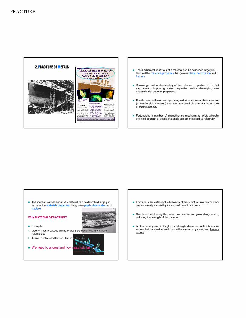
WHY MATERIALS FRACTURE?WHY MATERIALS FRACTURE?
�� Examples: Examples:
1.1. Liberty ships produced during WW2: steel became brittle in northLiberty ships produced during WW2: steel became brittle in north
Atlantic sea Atlantic sea
2.2. Titanic: ductile Titanic: ductile –– brittle transition in cold waterbrittle transition in cold water
�� We need to understand how materials failWe need to understand how materials fail
�� Fracture is the catastrophic breakFracture is the catastrophic break--up of the structure into two or more up of the structure into two or more
pieces, usually caused by a structural defect or a crack. pieces, usually caused by a structural defect or a crack.
�� Due to service loading the crack may develop and grow slowly in Due to service loading the crack may develop and grow slowly in size, size,
reducing the strength of the material. reducing the strength of the material.
�� As the crack grows in length, the strength decreases until it beAs the crack grows in length, the strength decreases until it becomes comes
so low that the service loads cannot be carried any more, and so low that the service loads cannot be carried any more, and fracture fracture
occursoccurs. .
FRACTURE
• Three stages of fracture:
1. Crack initiation. Crack will initiate at the point of stress concentration (scratches, fillets, threads, dents) when the internal stress cannot cope with the applied stress.
2. Crack propagation. The applied force will propagate the crack.
• Stage I: propagates very slowly along crystallographic planes of high shear stress and may constitute either a large or small fraction of the fatigue life of a specimen.
• Stage II: the crack growth rate increases and changes direction, moving perpendicular to the applied stress.
3. Fracture. Crack that exceeds a critical size will cause fracture to occur.
THE PROCESS OF FRACTURE
�� Common causes of fracture are:Common causes of fracture are:
�� Incorrect material selectionIncorrect material selection
�� Poor designPoor design
� Holes. Either incorporated in the design for aesthetic purposes or otherwise. Could also be due to macroscopic defect within the materials.
�� Use of new design or material, which produces unexpected resultsUse of new design or material, which produces unexpected results
� surface damage. Due to mechanical load such as scratching or surface roughness.
� Environment. High temperature and pressure, as well as corrosive environment increase the cause of fracture.
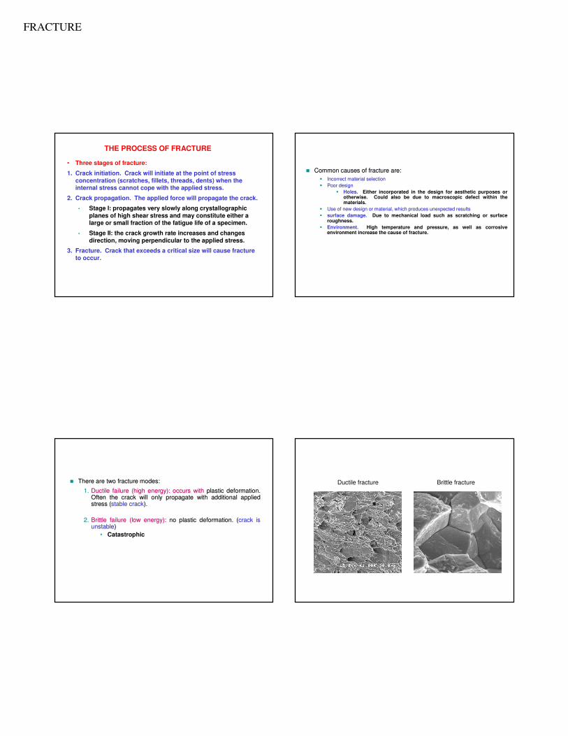
�� There are two fracture modes:There are two fracture modes:
1.1. Ductile failure (high energy): occurs withDuctile failure (high energy): occurs with plastic deformation. plastic deformation. Often the crack will only propagate with additional applied Often the crack will only propagate with additional applied stress (stress (stable crackstable crack).).
2.2. Brittle failure (low energy): Brittle failure (low energy): no plastic deformation. (no plastic deformation. (crack is crack is unstableunstable))
• Catastrophic
Brittle fractureDuctile fracture
FRACTURE
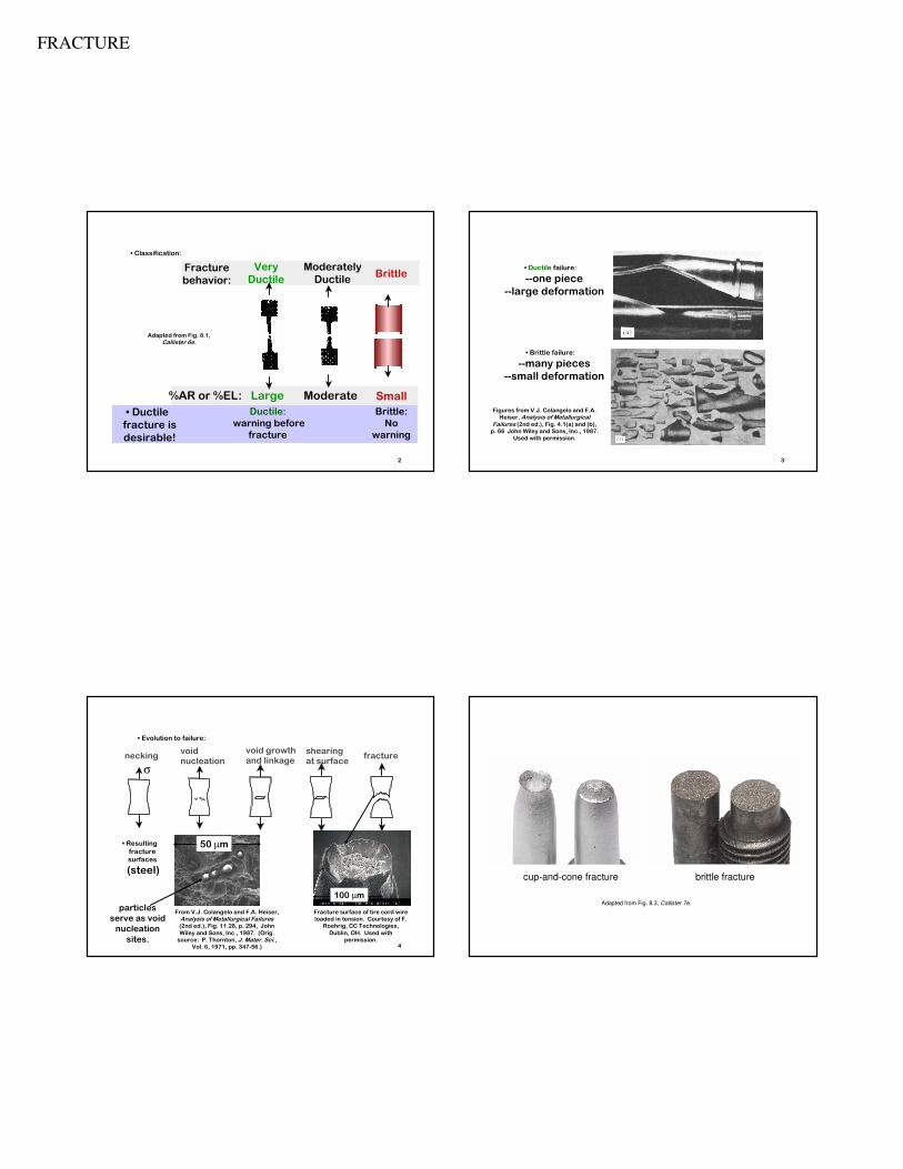
Very
Ductile
Moderately
DuctileBrittle
Fracture
behavior:
Large Moderate%AR or %EL: Small
2
• Ductile
fracture is
desirable!
• Classification:
Ductile:
warning before
fracture
Brittle:
No
warning
Adapted from Fig. 8.1,
Callister 6e.
DUCTILE VS BRITTLE FAILURE
3
• Ductile failure:
--one piece
--large deformation
• Brittle failure:
--many pieces
--small deformation
Figures from V.J. Colangelo and F.A.
Heiser, Analysis of Metallurgical Failures (2nd ed.), Fig. 4.1(a) and (b),
p. 66 John Wiley and Sons, Inc., 1987.
Used with permission.
EX: FAILURE OF A PIPE
4
• Evolution to failure:
neckingvoid nucleation
void growth and linkage
shearing at surface
fracture
σ
• Resulting
fracture
surfaces
(steel)
50 µm
particles
serve as void
nucleation
sites.
50 µm
100 µm
From V.J. Colangelo and F.A. Heiser,
Analysis of Metallurgical Failures(2nd ed.), Fig. 11.28, p. 294, John
Wiley and Sons, Inc., 1987. (Orig.
source: P. Thornton, J. Mater. Sci., Vol. 6, 1971, pp. 347-56.)
Fracture surface of tire cord wire
loaded in tension. Courtesy of F.
Roehrig, CC Technologies,
Dublin, OH. Used with
permission.
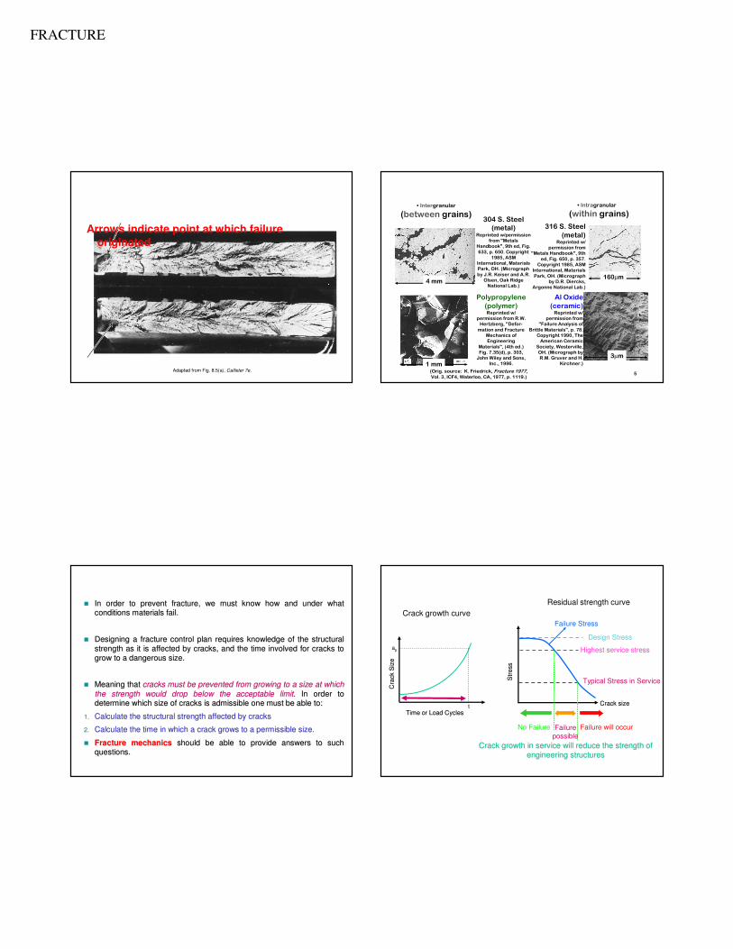
MODERATELY DUCTILE FAILURE Ductile vs. Brittle Failure
Adapted from Fig. 8.3, Callister 7e.
cup-and-cone fracture brittle fracture
FRACTURE
Brittle Failure
Arrows indicate point at which failure originated
Adapted from Fig. 8.5(a), Callister 7e.5
• Intergranular
(between grains)
• Intragranular
(within grains)
Al Oxide
(ceramic)Reprinted w/
permission from
"Failure Analysis of
Brittle Materials", p. 78.
Copyright 1990, The
American Ceramic
Society, Westerville,
OH. (Micrograph by
R.M. Gruver and H.
Kirchner.)
316 S. Steel
(metal)Reprinted w/
permission from
"Metals Handbook", 9th
ed, Fig. 650, p. 357.
Copyright 1985, ASM
International, Materials
Park, OH. (Micrograph
by D.R. Diercks,
Argonne National Lab.)
304 S. Steel
(metal)Reprinted w/permission
from "Metals
Handbook", 9th ed, Fig.
633, p. 650. Copyright
1985, ASM
International, Materials
Park, OH. (Micrograph
by J.R. Keiser and A.R.
Olsen, Oak Ridge
National Lab.)
Polypropylene
(polymer)Reprinted w/
permission from R.W.
Hertzberg, "Defor-
mation and Fracture
Mechanics of
Engineering
Materials", (4th ed.)
Fig. 7.35(d), p. 303,
John Wiley and Sons,
Inc., 1996.
3µm
4 mm160µm
1 mm(Orig. source: K. Friedrick, Fracture 1977,
Vol. 3, ICF4, Waterloo, CA, 1977, p. 1119.)
BRITTLE FRACTURE SURFACES
�� In order to prevent fracture, we must know how and under what In order to prevent fracture, we must know how and under what
conditions materials fail. conditions materials fail.
�� Designing a fracture control plan requires knowledge of the struDesigning a fracture control plan requires knowledge of the structural ctural
strength as it is affected by cracks, and the time involved for strength as it is affected by cracks, and the time involved for cracks to cracks to
grow to a dangerous size.grow to a dangerous size.
�� Meaning that Meaning that cracks must be prevented from growing to a size at which cracks must be prevented from growing to a size at which
the strength would drop below the acceptable limitthe strength would drop below the acceptable limit. In order to . In order to
determine which size of cracks is admissible one must be able todetermine which size of cracks is admissible one must be able to::
1.1. Calculate the structural strength affected by cracks Calculate the structural strength affected by cracks
2.2. Calculate the time in which a crack grows to a permissible size.Calculate the time in which a crack grows to a permissible size.
�� Fracture mechanicsFracture mechanics should be able to provide answers to such should be able to provide answers to such
questions.questions.Crack growth in service will reduce the strength of Crack growth in service will reduce the strength of
engineering structuresengineering structures
Crack growth curve
Time or Load CyclesTime or Load Cycles
Cra
ck S
ize
Cra
ck S
ize
ap
t
Residual strength curve
Highest service stress
Typical Stress in Service
Design Stress
Crack sizeCrack size
Str
ess
Str
ess
Failure Stress
Failure
possible
No Failure Failure will occur
FRACTURE
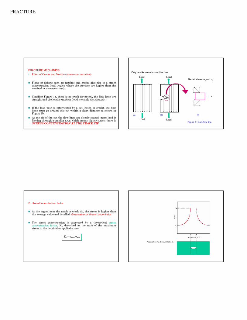
FRACTURE MECHANICSFRACTURE MECHANICS
1.1. Effect of Cracks and Notches (stress concentration)Effect of Cracks and Notches (stress concentration)
�� Flaws or defects such as: notches and cracks give rise to a streFlaws or defects such as: notches and cracks give rise to a stress ss concentration (local region where the stresses are higher than tconcentration (local region where the stresses are higher than the he nominal or average stress). nominal or average stress).
�� Consider Figure 1a, there is no crack (or notch), the flow linesConsider Figure 1a, there is no crack (or notch), the flow lines are are straight and the load is uniform (load is evenly distributed). straight and the load is uniform (load is evenly distributed).
�� If the load path is interrupted by a cut (notch or crack), the fIf the load path is interrupted by a cut (notch or crack), the flow low lines must go around this cut within a short distance as shown ilines must go around this cut within a short distance as shown in n Figure 3b. Figure 3b.
�� At the tip of the cut the flow lines are closely spaced: more loAt the tip of the cut the flow lines are closely spaced: more load is ad is flowing through a smaller area which means higher stress: there flowing through a smaller area which means higher stress: there is is STRESS CONCENTRATION AT THE CRACK TIPSTRESS CONCENTRATION AT THE CRACK TIP
Figure 1: loadFigure 1: load--flow lineflow line
(a)(a) (b)(b) (c)(c)
Only tensile stress in one directionOnly tensile stress in one direction
Biaxial stress: Biaxial stress: σσxx and and σσyy
Load Load Load Load
Load Load Load Load
2.2. Stress Concentration factorStress Concentration factor
�� At the region near the notch or crack tip, the stress is higher At the region near the notch or crack tip, the stress is higher than than the average value and is called the average value and is called stress raiser or stress concentratorstress raiser or stress concentrator
�� The stress concentration is expressed by a theoretical The stress concentration is expressed by a theoretical stress stress concentration factor,concentration factor, KKtt, described as the ratio of the maximum , described as the ratio of the maximum stress to the nominal or applied stress: stress to the nominal or applied stress:
KKtt = = σσmaxmax//σσnomnom
Concentration of Stress at Crack Tip
Adapted from Fig. 8.8(b), Callister 7e.
FRACTURE
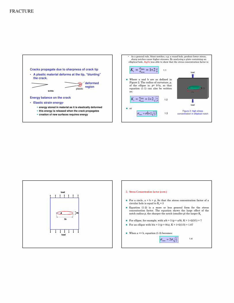
Crack Propagation
Cracks propagate due to sharpness of crack tip
• A plastic material deforms at the tip, “blunting”the crack.
deformed region
brittle
Energy balance on the crack
• Elastic strain energy-
� energy stored in material as it is elastically deformed
� this energy is released when the crack propagates
� creation of new surfaces requires energy
plastic
�� Where a and b are as defined in Where a and b are as defined in
Figure 2. The radius of curvature, Figure 2. The radius of curvature, ρρ, ,
of the ellipse is: of the ellipse is: ρρ= b= b22/a, so that /a, so that
equation (1equation (1--1) can also be written 1) can also be written
as:as:
�� oror
Ktabnom
= = +σσ
max 1 2
Kta
nom= = +σ
σ ρmax 1 2
( )ρσσ a21max +=
1.11.1
1.31.3
1.21.2
loadload
loadload
2a2a
2b2bρρ
Figure 2: high stress Figure 2: high stress
concentration in elliptical notchconcentration in elliptical notch
•• As a general rule, blunt notches, As a general rule, blunt notches, e.ge.g: a round hole, produce lower stress, : a round hole, produce lower stress,
sharp notches cause higher stresses. By analysing a plate contaisharp notches cause higher stresses. By analysing a plate containing an ning an
elliptical hole, elliptical hole, InglisInglis was able to show that the stress concentration factor is:was able to show that the stress concentration factor is:
2b2b
2a2a
ρρρρρρρρ
loadload
loadload
2b
2a
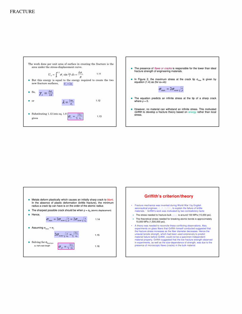
2.2. Stress Concentration factor (cont.) Stress Concentration factor (cont.)
�� For a circle, a = b = For a circle, a = b = ρρ, So that the stress concentration factor of a , So that the stress concentration factor of a
circular hole is equal to Kcircular hole is equal to Kt t = 3 = 3
�� Equation (1Equation (1--2) is a more or less general form for the stress 2) is a more or less general form for the stress
concentration factor. The equation shows the large effect of theconcentration factor. The equation shows the large effect of the
notch radius notch radius ρρ, the sharper the notch (smaller , the sharper the notch (smaller ρρ) the larger K) the larger Ktt
�� For ellipse, for example, with a/b = 3 (For ellipse, for example, with a/b = 3 (ρρ = a/9), K = 1+2(3/1) = 7= a/9), K = 1+2(3/1) = 7
�� For an ellipse with b/a = 3 (For an ellipse with b/a = 3 (ρρ = 9/a), K = 1+2(1/3) = 1.67= 9/a), K = 1+2(1/3) = 1.67
�� When a >> b, equation (1When a >> b, equation (1--3) becomes:3) becomes:
ρσσ a2max = 1.41.4
FRACTURE
aaoo
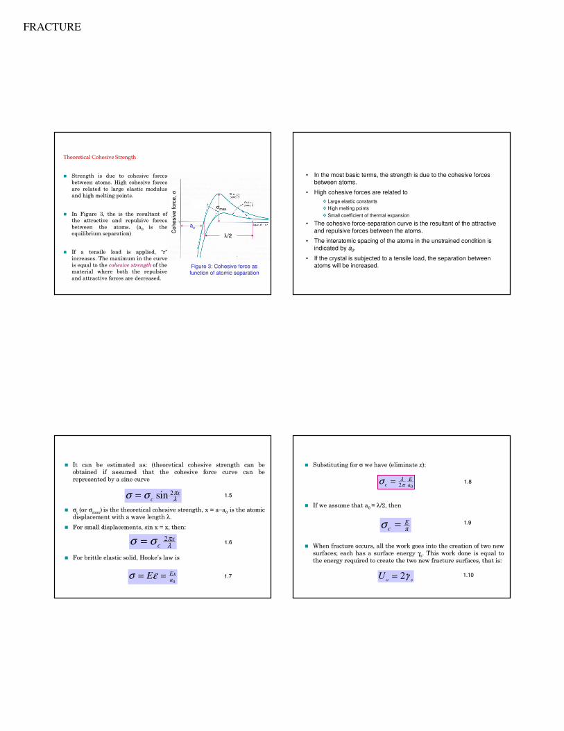
Figure 3: Cohesive force as Figure 3: Cohesive force as
function of atomic separationfunction of atomic separation
Coh
esiv
e f
orc
e,
Coh
esiv
e f
orc
e,
σσ
σσmaxmax
λλ/2/2
Theoretical Cohesive StrengthTheoretical Cohesive Strength
�� Strength is due to cohesive forces Strength is due to cohesive forces
between atoms. High cohesive forces between atoms. High cohesive forces
are related to large elastic modulus are related to large elastic modulus
and high melting points. and high melting points.
�� In Figure 3, the is the resultant of In Figure 3, the is the resultant of
the attractive and repulsive forces the attractive and repulsive forces
between the atoms. (abetween the atoms. (a0 0 is the is the
equilibrium separation)equilibrium separation)
�� If a tensile load is applied, If a tensile load is applied, ““rr””
increases. The maximum in the curve increases. The maximum in the curve
is equal to the is equal to the cohesive strengthcohesive strength of the of the
material where both the repulsive material where both the repulsive
and attractive forces are decreased. and attractive forces are decreased.
• In the most basic terms, the strength is due to the cohesive forces
between atoms.
• High cohesive forces are related to
� Large elastic constants
� High melting points
� Small coefficient of thermal expansion
• The cohesive force-separation curve is the resultant of the attractive
and repulsive forces between the atoms.
• The interatomic spacing of the atoms in the unstrained condition is
indicated by a0.
• If the crystal is subjected to a tensile load, the separation between atoms will be increased.
�� It can be estimated as: (theoretical cohesive strength can be It can be estimated as: (theoretical cohesive strength can be
obtained if assumed that the cohesive force curve can be obtained if assumed that the cohesive force curve can be
represented by a sine curve represented by a sine curve
�� σσc c (or (or σσmaxmax)) is the theoretical cohesive strength, x = ais the theoretical cohesive strength, x = a−−aa00 is the atomic is the atomic
displacement with a wave length displacement with a wave length λλ..
�� For small displacements, sin x = x, thenFor small displacements, sin x = x, then::
�� For brittle elastic solid, For brittle elastic solid, HookeHooke’’ss law islaw is
σ σ πλ= c
xsin 2
σ σ πλ= c
x2
0aExE == εσ 1.71.7
1.61.6
1.51.5
�� Substituting for Substituting for σσ we have (eliminate we have (eliminate xx):):
�� If we assume that aIf we assume that a0 0 = = λλ/2, then/2, then
�� When fracture occurs, all the work goes into the creation of twoWhen fracture occurs, all the work goes into the creation of two new new
surfaces; each has a surface energy surfaces; each has a surface energy γγss. This work done is equal to . This work done is equal to
the energy required to create the two new fracture surfaces, thathe energy required to create the two new fracture surfaces, that is:t is:
σ λπc
Ea=
2 0
σ πcE=
U o s= 2γ 1.101.10
1.91.9
1.81.8
FRACTURE
The work done per unit area of surface in creating the fracture The work done per unit area of surface in creating the fracture is the is the
area under the stressarea under the stress--displacement curve.displacement curve.
�� But this energy is equal to the energy required to create the twBut this energy is equal to the energy required to create the two o
new fracture surfaces, new fracture surfaces,
�� So, So,
�� oror
�� Substituting 1.12 into Substituting 1.12 into eqeq. 1.8 . 1.8
givesgives
π
λσγ2
cs =
c
sσ
πγλ 2=
o
sa
Ec
γσ =
∫ ==2/
0
20 sin
λ
λπ
π
λσσ cx
c dxU
soU γ2=
1.111.11
1.121.12
1.131.13
�� The presence of The presence of flaws or cracksflaws or cracks is responsible for the lower than ideal is responsible for the lower than ideal fracture strength of engineering materials. fracture strength of engineering materials.
�� In Figure 2, the maximum stress at the crack tip In Figure 2, the maximum stress at the crack tip σσmaxmax is given by is given by equation (1.4) as (for a>>b):equation (1.4) as (for a>>b):
�� The equation predicts an infinite stress at the tip of a sharp cThe equation predicts an infinite stress at the tip of a sharp crack rack where where ρρ = 0. = 0.
�� However, no material can withstand an infinite stress. This motiHowever, no material can withstand an infinite stress. This motivated vated Griffith Griffith to develop a fracture theory based on to develop a fracture theory based on energyenergy rather than local rather than local stress. stress.
σ σ ρmax = 2 noma
�� Metals deform plastically which causes an initially sharp crack Metals deform plastically which causes an initially sharp crack to to bluntblunt. .
In the absence of plastic deformation (brittle fracture), the miIn the absence of plastic deformation (brittle fracture), the minimum nimum
radius a crack tip can have is on the order of the atomic radiusradius a crack tip can have is on the order of the atomic radius
�� The sharpest possible crack should be when The sharpest possible crack should be when ρρ = a= a0 0 (atomic displacement)(atomic displacement)
�� Hence,Hence,
�� Assuming Assuming σσmaxmax = = σσc c
�� Solving for Solving for σσfracturefracture
a= half crack lengtha= half crack length
022max a
anom
anom σσσ ρ == 1.141.14
002 a
Eaa
nomsγσ = 1.151.15
aE
frs
4
γσ = 1.161.16
• Fracture mechanics was invented during World War I by English
aeronautical engineer, A. A. Griffith, to explain the failure of brittle
materials.[1] Griffith's work was motivated by two contradictory facts:
� The stress needed to fracture bulk glass is around 100 MPa (15,000 psi).
� The theoretical stress needed for breaking atomic bonds is approximately
10,000 MPa (1,500,000 psi).
• A theory was needed to reconcile these conflicting observations. Also,
experiments on glass fibers that Griffith himself conducted suggested that
the fracture stress increases as the fiber diameter decreases. Hence the
uniaxial tensile strength, which had been used extensively to predict
material failure before Griffith, could not be a specimen-independent
material property. Griffith suggested that the low fracture strength observed
in experiments, as well as the size-dependence of strength, was due to the
presence of microscopic flaws (cracks) in the bulk material.
Griffith's criterion/theory
FRACTURE
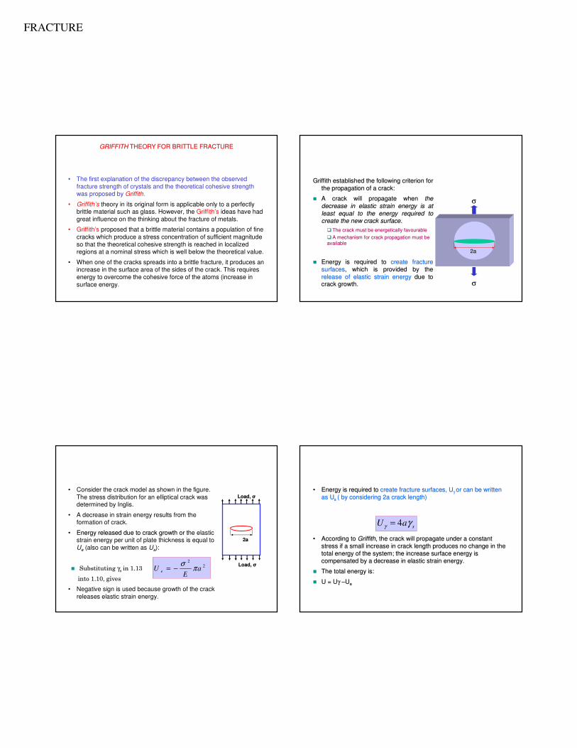
• The first explanation of the discrepancy between the observed
fracture strength of crystals and the theoretical cohesive strength was proposed by Griffith.
• Griffith’s theory in its original form is applicable only to a perfectly brittle material such as glass. However, the Griffith’s ideas have had
great influence on the thinking about the fracture of metals.
• Griffith’s proposed that a brittle material contains a population of fine
cracks which produce a stress concentration of sufficient magnitude
so that the theoretical cohesive strength is reached in localized regions at a nominal stress which is well below the theoretical value.
• When one of the cracks spreads into a brittle fracture, it produces an increase in the surface area of the sides of the crack. This requires
energy to overcome the cohesive force of the atoms (increase in
surface energy.
GRIFFITHGRIFFITH THEORY FOR BRITTLE FRACTURETHEORY FOR BRITTLE FRACTURE
Griffith established the following criterion for Griffith established the following criterion for
the propagation of a crack:the propagation of a crack:
�� A crack will propagate when A crack will propagate when the the
decrease in elastic strain energy is at decrease in elastic strain energy is at
least equal to the energy required to least equal to the energy required to
create the new crack surface. create the new crack surface.
�� The crack must be energetically favourableThe crack must be energetically favourable
�� A mechanism for crack propagation must be A mechanism for crack propagation must be
availableavailable
�� Energy is required to Energy is required to create fracture create fracture
surfacessurfaces, which is provided by the , which is provided by the
release of elastic strain energyrelease of elastic strain energy due to due to
crack growth.crack growth. σσ
σσ
2a2a
2a2a
Load, Load, σσ
Load, Load, σσ
• Consider the crack model as shown in the figure.
The stress distribution for an elliptical crack was determined by Inglis.
• A decrease in strain energy results from the formation of crack.
•• Energy released due to crack growth or Energy released due to crack growth or tthe elastic strain energy per unit of plate thickness is equal to
Ue (also can be written as Ua):
�� Substituting Substituting γγs s in in 1.13 1.13
into 1.10, gives into 1.10, gives
• Negative sign is used because growth of the crack
releases elastic strain energy.
22
aE
U e πσ
−=
•• Energy is required to Energy is required to create fracture surfaces, Ucreate fracture surfaces, Uγγ or can be written or can be written
as Uas Us s ( by considering 2a crack length) ( by considering 2a crack length)
•• According to According to GriffithGriffith, the crack will propagate under a constant , the crack will propagate under a constant
stress if a small increase in crack length produces no change instress if a small increase in crack length produces no change in the the
total energy of the system; the increase surface energy is total energy of the system; the increase surface energy is
compensated by a decrease in elastic strain energy. compensated by a decrease in elastic strain energy.
�� The total energy is:The total energy is:
�� U = UU = Uγγ ––UUee
saU γγ 4=
FRACTURE
Energ
y, U
Energ
y, U
Crack Length, aCrack Length, a
Strain EnergyStrain EnergyTotal Total
EnergyEnergy
U = UU = Uγγ--UUaa
Surface EnergySurface Energy
Critical Crack LengthCritical Crack Length
dU/da=0dU/da=0
a*a*
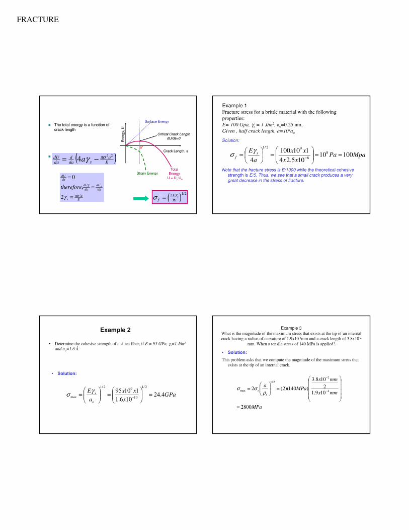
�� The total energy is a function of The total energy is a function of
crack lengthcrack length
�� At the critical crack length, a*At the critical crack length, a*( )Ea
sdad
dadU a
22
4 πσγ −=
Ea
s
dadU
dadU
dadU
atherefore2
2
,
0
πσ
γ
γ =
=
=
( )σ γπfEa
s= 2 1 2/
Solution:
Note that the fracture stress is E/1000 while the theoretical cohesive strength is E/5. Thus, we see that a small crack produces a very
great decrease in the stress of fracture.
MpaPaxx
xx
a
E sf 10010
105.24
110100
4
8
6
92/1
==
=
=
−
γσ
Example 1Fracture stress for a brittle material with the following
properties:
E= 100 Gpa, γs = 1 J/m2, ao=0.25 nm,
Given , half crack length, a=104ao
• Determine the cohesive strength of a silica fiber, if E = 95 GPa, γs=1 J/m2
and ao=1.6 Å.
• Solution:
GPax
xx
a
E
o
s 4.24106.1
110952/1
10
92/1
max =
=
=
−
γσ
Example 2
• Solution:
This problem asks that we compute the magnitude of the maximum stress that
exists at the tip of an internal crack.
MPa
mmx
mmx
MPaa
to
2800
109.1
2
108.3
)140)(2(24
2
2/1
max
=
=
=
−
−
ρσσ
Example 3What is the magnitude of the maximum stress that exists at the tip of an internal
crack having a radius of curvature of 1.9x10⁻⁴mm and a crack length of 3.8x10⁻²
mm. When a tensile stress of 140 MPa is applied?
FRACTURE
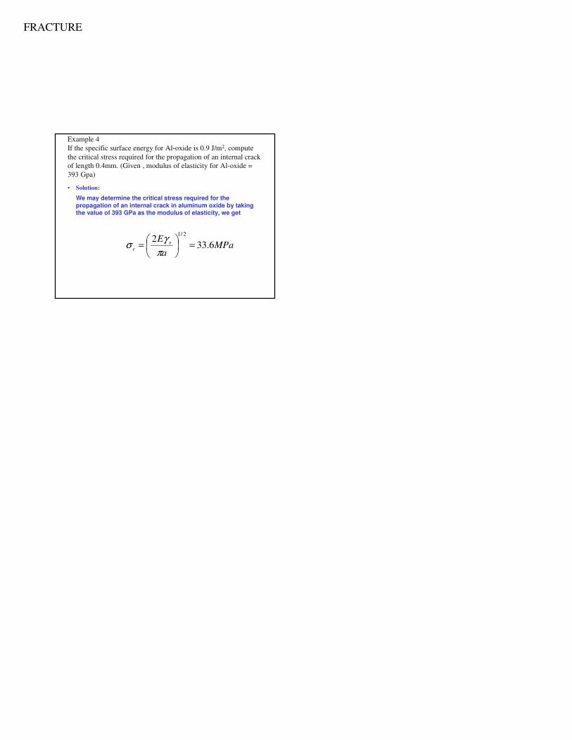
Example 4
If the specific surface energy for Al-oxide is 0.9 J/m2, compute
the critical stress required for the propagation of an internal crack
of length 0.4mm. (Given , modulus of elasticity for Al-oxide =
393 Gpa)
• Solution:
We may determine the critical stress required for the propagation of an internal crack in aluminum oxide by taking the value of 393 GPa as the modulus of elasticity, we get
MPaa
E sc 6.33
22/1
=
=
π
γσ