fracture assessments of marine pipelines and subsea … · 2017-08-04 · fracture assessments of...
TRANSCRIPT

Fracture Assessments of MarinePipelines and Subsea Components
in Hostile Environments:Critical Concerns and Recent
Developments
Claudio Ruggieri
NAMEFFracture Mechanics and Structural Integrity Research Group
Faculty of EngineeringUniversity of São Paulo - Brazil

Outline
Challenges in Pipeline Safety Standards:Linking Design and Operation
Current Practices and Standards for Defectand Safety Assessments of Pipelines
Innovative Approaches as More Rational andYet More Efficient Integrity AssessmentProcedures for High Perfomance Pipelines
Some Key Critical Concerns Driving FurtherResearch and Development

Going Farther and Deeper......
Increasing Demand forFossil Fuels, IncludingNatural Gas, is PushingOil and Gas Exploitation
and Production toFarther and Deeper
Reservois in Difficult andHostile Environments
Technological Challenges in Pipeline andRiser Design, Installation, Operation,
Inspection and Repair
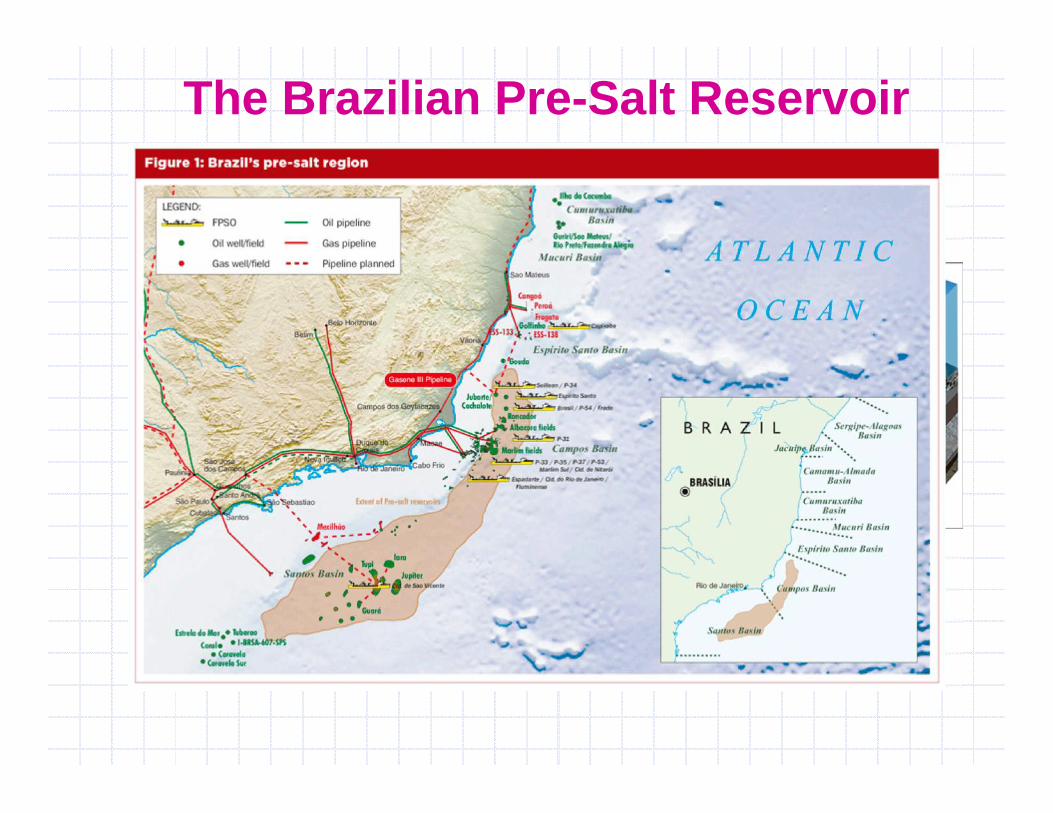
The Brazilian Pre-Salt Reservoir

The Brazilian Pre-Salt Reservoir

Key Characteristics
More than 2500 m Water Depth. 2000 m Thickness Salt Layer. Gas Pipeline Larger than 18” in
2500 m Long Distance to Shore (300 km) High CO2 Content (8 ~ 20%)

Technological Challenges
Impact on FFS / ECA Procedures and HowDoes It Affect Tolerable Defect Sizes?
Higher Stresses / StrainsDuring Installation Larger Thickness
Including Weldments
Sour Conditions

The “Mysterious” Design Factor....
High Design Stresses Do Not Cause Failure.Damage Does!
The 0.72 Design Factor isa Historical Factor SetMore than 50 Years Ago ! There is No Rational
and Convincing BasisAgainst Increasing It.

Fracture is Always a Concern ....
Failure of Brazilian Pressure Vessel (2000)(Fracture Initiated at Weld Defect)

Conventional Defect Assessments
FFS or ECA Analysis Required
Fundamental Procedure is Based on the “GoodWorkmanship” Philosophy To Ensure That thePipeline/Riser is Free of Fabrication Defects
However, Larger and Often Severe Defects WillInvariably Occur During the Pipeline and RiserService Life.

Two-Parameter Assessment Line Describingthe Interacion of Two Failure Modes:Brittle Fracture and Plastic Collapse
Failure Assessment Diagram Approach

BS 7910 Level 2A

Key Assumption is that the FAD CurveDoes Not Depend on SpecimenGeometry and Strain Hardening:
High Constraint ConditionsLow to Moderate Ductile Material
FAD Approach
More Important, FAD Procedure is aStress-Based Approach !

Current Scenario
New Methods Should be Developed
There is Growing Concern Supported byStrong Field Evidences that Conventional FFSProcedures are not Necessarily Applicable to
Newer Materials and Complex Conditions:X100 Grade Steel, Ultra Deep Waters, Heavy
Thickness Pipes, Sour Environment, etc.

Constraint Effects on Toughness

Flawed Pipes vs. SE(B) Specimens
Cravero and Ruggieri (2007)

Flawed Pipes vs. SE(T) Specimens
Cravero and Ruggieri (2007)

V5
V6
-1 -0.8 -0.6 -0.4 -0.2 0 0.2 0.4 0.6 0.8 1
-1
-0.8
-0.6
-0.4
-0.2
0
0.2
0.4
0.6
0.8
1
V5
V6
-1 -0.8 -0.6 -0.4 -0.2 0 0.2 0.4 0.6 0.8 1
-1
-0.8
-0.6
-0.4
-0.2
0
0.2
0.4
0.6
0.8
1
SE(T)-P a/W=0,520” Pipe a/t=0,5
by
by
bx
bx
Crack-Tip Plastic Zones
Cravero and Ruggieri (2007)

Constraint Modified FAD Approach
]1[0rQmat
Qmat LKK
]1[)( rQrr LLfK
ToughnessCorrection

Constraint Modified FAD

Strain-Based Analysis Defines a Limit StateCondition in Which Structural Behavior isControlled by Imposed Displacements
Strain-Based Analysis
The Collapse Analysis Built Into FAD ProceduresRelies on Determinig Net Section Yielding in theCrack Ligament
For Higher Grade Steels or Overmatched GirthWelds the Applied Strain Can Be Much Higher
than the Yield Strain

Strain-Based Analysis
When the Material is in the Plastic Range, SmallChanges in Stress Cause Large Changes in Strain

Post-Yield Behavior Does Affect the TolerableDefect Size in a Structural Component
Strain-Based Analysis
After Yielding, the Evolving Near-Tip Stressesand Crack Driving Forces (J, CTOD) StronglyDepend on the Plastic Straining Capacity
Pipe Steels with Lower YT-Ratios (X60) May AllowLarger Defects than Higher YT-Ratios (X100)

Fracture Assessment Using API 579 L2
0
0.2
0.4
0.6
0.8
1
1.2
0 0.2 0.4 0.6 0.8 1 1.2
rK
rL
API Level 2Limit LoadCorrection
%25.0f

On-Going Research
Development of Test Procedures forConstraint-Designed SE(T) Specimens
FFS Procedures and Biaxial Loading Effectson Reeled Risers
Structural Integrity Assessments of LinedPipes for Reeling
Fatigue and Toughness Behavior of GirthWelds of Lined Pipes under H2 Environment

Constraint-Designed Test Specimens

Pipeline and Riser Installation
Riser Installation by Reeling

FFS Procedures for Reeled Risers

Pipe Reeling Behavior
(From SINTEF Materials Laboratory)

Pipe Reeling Behavior
(From SINTEF Materials Laboratory)

FFS Procedures for Reeled Risers

FFS Procedures for Reeled Risers
Full Compendium of h1 Factors Generated byChiodo & Ruggieri in Polynomial Formfor Easy Manipulation and Codification
Proportionality Between J (CTOD) andApplied Loading is Very Good for High andModerate Hardening (All Crack Config.) andLow Hardening (Shallow Cracks)
Robust Procedure for Most Applications

Application to Pipe Reeling
Estimation of J Based Upon Applied Strain(e.g., DNV-OS-F101)
API Grade 5L X60

J vs. Global Response

Estimation of Maximum CrackDriving Forces in Pipe Reeling

Lined Pipes
Lined pipes consist of a C-Mn pipe which has a layer of CRA incontact with the production fluid and hence, its corrosiveenvironment. The layer of Corrosion Resistant Alloy (CRA) is appliedthrough a mechanical bond between the CRA and the C-Mn pipe.
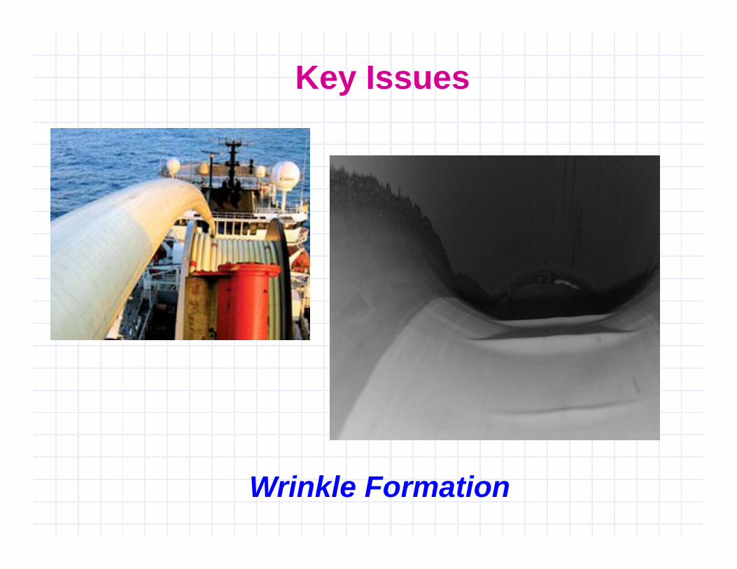
Key Issues
Wrinkle Formation

Key Issues
Fatigue and Fracture Behavior of Girth WeldsIncluding Hydrogen Assisted Cracking
Summary
Exploitation and Production of Oil and Gas inUltradeep and Hostile Environment Represent Newand Difficult Challenges which Impact Directly theSafety and Integrity Levels of Pipelines and Risers
Application of Current FFS Procedures to NewerMaterials and Complex/Severe Conditions Can Notbe Made by Simple Ad-Hoc Extension ofConventional Engineering Methodologies
Innovative and Yet More Rational and ReliableApproaches Must Be Developed!

Thank you!