fractionator tool kit - honeywell · to mpph conv_fac(10) stream 10 flow input unit conversion...
TRANSCRIPT

Fractionator Tool KitUser’s Guide
3/98

.

Robust Multivariable Predictive Control Technology
Fractionator Tool KitUser’s Guide
Revision 1.1
3/98

Fractionator Tool Kit 04/99Honeywell Inc.
iv
Copyright, Notices, and Trademarks
Printed in U.S.A. – © Copyright 1997 by Honeywell Inc.
While this information is presented in good faith and believed to be accurate,Honeywell disclaims the implied warranties of merchantability and fitness for a
particular purpose and makes no express warranties except as may be stated inits written agreement with and for its customer.
In no event is Honeywell liable to anyone for any indirect, special or consequentialdamages. The information and specifications in this document are subject to
change without notice.
TDC 3000 and TotalPlant are U. S. registered trademarks of Honeywell Inc.
Other product names are trademarks of their respective owners.
HoneywellIndustrial Automation and Control
2500 West Union HillsPhoenix, AZ 85023
(602) 313-4788

04/99 Fractionator Tool Kit vHoneywell Inc.
Table of Contents
COPYRIGHT, NOTICES, AND TRADEMARKS ...................................................... IV
TABLE OF CONTENTS ............................................................................................ V
TOOL KIT ITEM .................................................................................................... TABASTM D86 TEMPERATURE CALCULATION............................................................................... 1
FLASH POINT CALCULATION..................................................................................................... 2
FLASH POINT CALCULATION (REBOILED)............................................................................... 3
FREEZE POINT CALCULATION................................................................................................... 4
INTERNAL LIQUID AND VAPOR CALCULATION ....................................................................... 5
LABORATORY UPDATING SYSTEM........................................................................................... 6
POUR POINT CALCULATION ...................................................................................................... 7
PRESSURE COMPENSATED TEMPERATURE CALCULATION................................................ 8
REID VAPOR PRESSURE CALCULATION.................................................................................. 9
TEMPERATURE CORRECTED SPECIFIC GRAVITY................................................................ 10
WATSON K CALCULATION .......................................................................................................11

04/99 Fractionator Tool Kit viHoneywell Inc.

Hi-Spec Solutions
Honeywell Hi-Spec Solutions • 16404 N. Black Canyon Hwy. • Phoenix, AZ 85023
Advanced Control Package
ASTM D86 Temperature Calculation
CONTROLLED
April 1995Revision 3.0

Hi-Spec Solutions
ASTM D86 Temperature Calculation Revision HistoryRevision 3.0
16404 North Black Canyon Hiway • Phoenix, Az 85023325 Rolling Oaks Dr • Thousand Oaks, CA 91361-1200
10333 Richmond, Suite 1110 • Houston, Tx 77042Chilworth Research Centre • Southampton, United Kingdom • SO1 7NP

Hi-Spec Solutions
ASTM D86 Temperature Calculation Contents
Revision 3.0
Table of Contents
Acronym List ........................................................................................................................................1
Overview...............................................................................................................................................1
Hardware and Software Requirements .................................................................................................3
Instrumentation (Process Inputs)...........................................................................................................4
Process Diagram ...................................................................................................................................5
Detailed Description .............................................................................................................................6Point Structure ..............................................................................................................................7Process Inputs ...............................................................................................................................8Configuration Inputs ...................................................................................................................10Calculation Outputs ....................................................................................................................14
Error Codes .........................................................................................................................................17Diagnostic Error Codes...............................................................................................................18Molecular Weight Error Codes ...................................................................................................22EFV Temperature Error Codes ...................................................................................................23EFV Temperature to ASTM D86 Temperature Error Codes......................................................24
Configuration and Tuning...................................................................................................................25Biases in the ASTM D86 Temperature Calculation Program.....................................................26Tuning Parameters ......................................................................................................................27
Algorithms ..........................................................................................................................................28
Installation Procedure .........................................................................................................................33
Preparation for Installation..................................................................................................................34
Custom Data Segment (CDS) and Parameter List (PL) Installation...................................................35
Building ASTM D86 Calculation Point..............................................................................................36
Configuration Graphics Installation....................................................................................................37
Configure Calculation Point ...............................................................................................................38Point Configuration Using Graphic D86_CFG...........................................................................39Point Configuration through Direct CDS Entry..........................................................................44
Link CL Programs...............................................................................................................................49

Hi-Spec Solutions
ASTM D86 Temperature Calculation Acronym List
Revision 3.0
Acronym List
Term Acronym
Application Module AM
Local Control Network LCN
Universal Station US
control language CL
process variable PV
custom data segment CDS
pounds per square inch psi
Parameter List PL
CL object code file extension AO
Universal Control Network UCN
Equivalent Flash Vaporization EFV
Fluidized Catalytic Cracked FCC

Hi-Spec Solutions
ASTM D86 Temperature Calculation Overview
Revision 3.0 1
Overview
Definition. ASTM D86 temperature is the temperature to which a product must beheated, under prescribed conditions, to distill the desired volume percent of the originalsample.
Application. The ASTM D86 temperatures of a hydrocarbon fraction is an importantspecification for motor gasoline, aviation gasoline, naphtha, kerosene, gas oils, distillatefuel oils, and similar petroleum products. ASTM D86 temperatures define thevolatility characteristics or the boiling range of the product.
Calculation. The ASTM D86 temperature calculation program calculates the inferentialASTM D86 temperature of a hydrocarbon product based on:
• Processinputs :
Temperature, pressure, and flows
• Characterizationinputs:
Watson K, specific gravity and optionallymolecular weight
• Calculatedvalues:
Selected ASTM D86 temperature, equilibriumflash vaporization temperature, effectivepressure, mole fraction and optionally molecularweight.
Incentive. 1. To indicate how closely a hydrocarbon stream is meeting the ASTMD86 temperature specification.
2. To eliminate dead time associated with laboratory analysis and on-lineanalyzers.
3. To provide a real-time input for use in advanced control applications.

Hi-Spec Solutions
ASTM D86 Temperature Calculation Overview
Revision 3.0 2
6050403020100 600
610
620
630
640
650
660
Calc 90%Lab 90%
LGO 90% Cutpoint Data
Sample Number

Hi-Spec Solutions
ASTM D86 Temperature Calculation Hardware and Software Requirements
Revision 3.0 3
Hardware and Software Requirements
Requirement Description
Hardware Platform TDC 3000 AM
Special Boards None
Other Computing Systems None
LCN Release Release 300 or later
AM Load Modules None
US Load Modules None
Other Packages None
Other Control Applications None
Software Inputs Gravities and Watson K factors for the input streams must exist aspoints on the LCN

Hi-Spec Solutions
ASTM D86 Temperature Calculation Instrumentation (Process Inputs)
Revision 3.0 4
Instrumentation (Process Inputs)
Process Input1 Required Recommended
Input stream flow rates XProduct temperature XProduct pressure X
1 Required inputs can sometimes be obtained by inference. However, calculations based upon inferred data can be less accurate than calculations based upon direct readings.

Hi-Spec Solutions
ASTM D86 Temperature Calculation Process Diagram
Revision 3.0 5
Process Diagram
STEAM
KEROSENE
NAPHTHA
OFF GAS
T32
P23
T31 FC4
FC5
TOWER
FC3
FC2FC1
TC2
INTERNAL INTERNALVAPOR REFLUX
PUMPAROUND

Hi-Spec Solutions
ASTM D86 Temperature Calculation Point Structure
Revision 3.0 6
Detailed Description
The tables in this section describe the following ASTM D86 Temperature CalculationPoint program architecture:
• Point Structure
• Process Inputs
• Configuration Inputs
• Calculation Outputs.

Hi-Spec Solutions
ASTM D86 Temperature Calculation Point Structure
Revision 3.0 7
Point Structure
Point Structure
Point Type Application Module Regulatory, CL
PV_Type CL
CTL_Type Any
Custom Data Segment D86_CDS.CL
Algorithm D86_EFV.CL
Insertion Point PV_ALG
Slot 5
Output The calculated inferential temperature of the selected D86 is displayed asthe point’s PV

Hi-Spec Solutions
ASTM D86 Temperature Calculation Process Inputs
Revision 3.0 8
Process Inputs
Process InputsCritical2
Parameter Description Units Yes No
FLOW_PT(1) Tagname for stream 1 flow input Any flow units X
FLOW_PT(2) Tagname for stream 2 flow input Any flow units X
FLOW_PT(3) Tagname for stream 3 flow input Any flow units X
FLOW_PT(4) Tagname for stream 4 flow input Any flow units X
FLOW_PT(5) Tagname for stream 5 flow input Any flow units X
FLOW_PT(6) Tagname for stream 6 flow input Any flow units X
FLOW_PT(7) Tagname for stream 7 flow input Any flow units X
FLOW_PT(8) Tagname for stream 8 flow input Any flow units X
FLOW_PT(9) Tagname for stream 9 flow input Any flow units X
FLOW_PT(10) Tagname for stream 10 flow input Any flow units X
GRAV_PT(1) Tagname for stream 1 gravity input °API or none (S.G.) X
GRAV_PT(2) Tagname for stream 2 gravity input °API or none (S.G.)X
GRAV_PT(3) Tagname for stream 3 gravity input °API or none (S.G.)X
GRAV_PT(4) Tagname for stream 4 gravity input °API or none (S.G.)X
GRAV_PT(5) Tagname for stream 5 gravity input °API or none (S.G.)X
GRAV_PT(6) Tagname for stream 6 gravity input °API or none (S.G.)X
GRAV_PT(7) Tagname for stream 7 gravity input °API or none (S.G.)X
GRAV_PT(8) Tagname for stream 8 gravity input °API or none (S.G.)X
GRAV_PT(9) Tagname for stream 9 gravity input °API or none (S.G.)X
GRAV_PT(10) Tagname for stream 10 gravity input °API or none (S.G.)X
MOLWT(1) Calculated/Entered molecular weight forstream 1
lb/mole X
MOLWT(2) Calculated/Entered molecular weight forstream 2
lb/mole X
Continued
2 Critical indicates that a bad input causes the output of the calculation to be set BAD.

Hi-Spec Solutions
ASTM D86 Temperature Calculation Process Inputs
Revision 3.0 9
Process Inputs (Continued)
Process Inputs
Critical
Parameter Description Units Yes No
MOLWT(3) Calculated/Entered molecular weight forstream 3
lb/mole X
MOLWT(4) Calculated/Entered molecular weight forstream 4
lb/mole X
MOLWT(5) Calculated/Entered molecular weight forstream 5
lb/mole X
MOLWT(6) Calculated/Entered molecular weight forstream 6
lb/mole X
MOLWT(7) Calculated/Entered molecular weight forstream 7
lb/mole X
MOLWT(8) Calculated/Entered molecular weight forstream 8
lb/mole X
MOLWT(9) Calculated/Entered molecular weight forstream 9
lb/mole X
MOLWT(10) Calculated/Entered molecular weight forstream 10
lb/mole X
PRESS_PT Tagname for pressure input Any pressure units X
TEMP_PT Tagname for temperature input °F or °C X
WATK_PT(1) Tagname for stream 1 Watson K factor None X
WATK_PT(2) Tagname for stream 2 Watson K factor None X
WATK_PT(3) Tagname for stream 3 Watson K factor None X
WATK_PT(4) Tagname for stream 4 Watson K factor None X
WATK_PT(5) Tagname for stream 5 Watson K factor None X
WATK_PT(6) Tagname for stream 6 Watson K factor None X
WATK_PT(7) Tagname for stream 7 Watson K factor None X
WATK_PT(8) Tagname for stream 8 Watson K factor None X
WATK_PT(9) Tagname for stream 9 Watson K factor None X
WATK_PT(10) Tagname for stream 10 Watson K factor None X

Hi-Spec Solutions
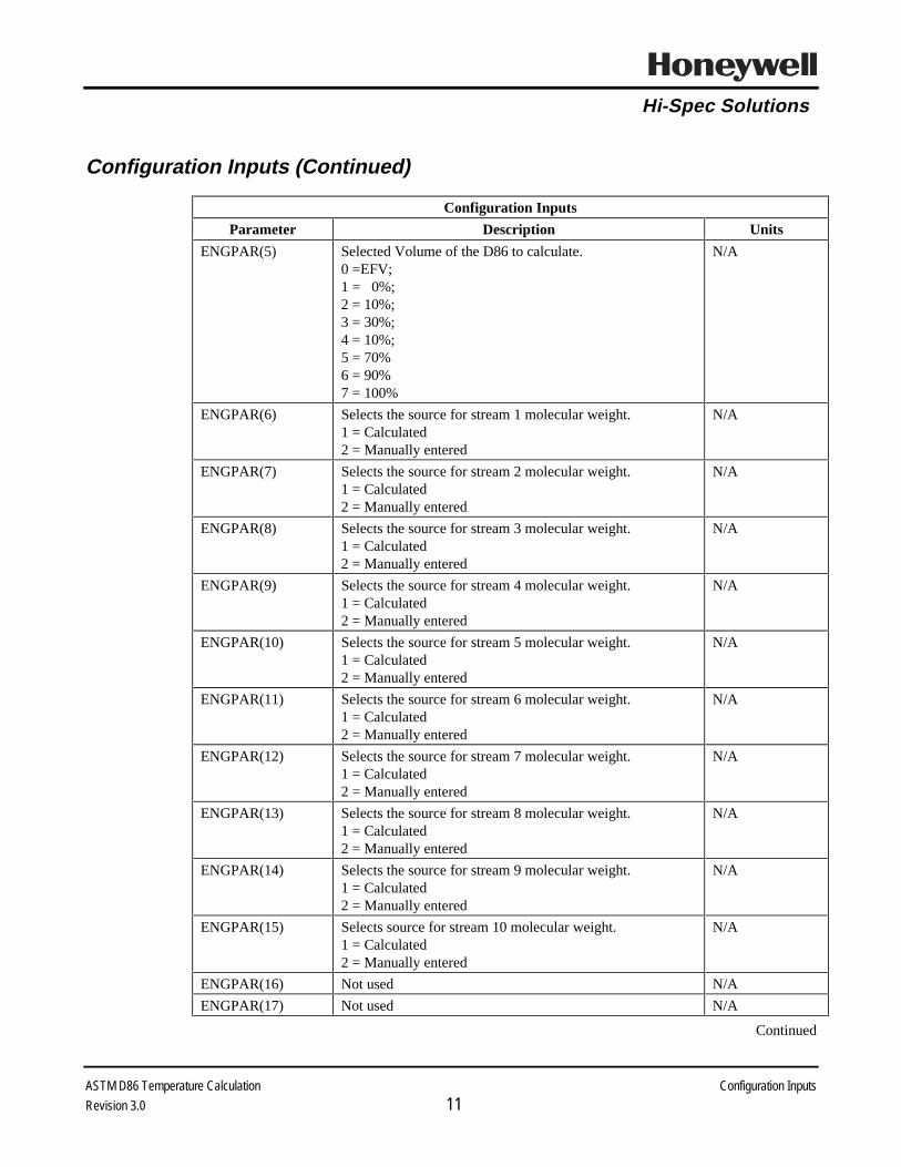
ASTM D86 Temperature Calculation Configuration Inputs
Revision 3.0 10
Configuration Inputs
Configuration Inputs
Parameter Description Units
CONV_FAC(1) Stream 1 flow input unit conversion factor From input unitsto MPPH
CONV_FAC(2) Stream 2 flow input unit conversion factor From input unitsto MPPH
CONV_FAC(3) Stream 3 flow input unit conversion factor From input unitsto MPPH
CONV_FAC(4) Stream 4 flow input unit conversion factor From input unitsto MPPH
CONV_FAC(5) Stream 5 flow input unit conversion factor From input unitsto MPPH
CONV_FAC(6) Stream 6 flow input unit conversion factor From input unitsto MPPH
CONV_FAC(7) Stream 7 flow input unit conversion factor From input unitsto MPPH
CONV_FAC(8) Stream 8 flow input unit conversion factor From input unitsto MPPH
CONV_FAC(9) Stream 9 flow input unit conversion factor From input unitsto MPPH
CONV_FAC(10) Stream 10 flow input unit conversion factor From input unitsto MPPH
CONV_FAC(11) PRESS_PT input unit multiplicative conversion factor From input unitsto PSI
CONV_FAC(12) Input temperature units flag0 = °F1 = °C
N/A
CONV_FAC(13) Input gravity type flag0 = API1 = Specific Gravity
N/A
CONV_FAC(14) Not used N/A
ENGPAR(1) Number of input flow streams N/A
ENGPAR(2) Local atmospheric pressure, used to convert input gauge toinput absolute units.
Same units asPRESS_PT
ENGPAR(3) Set calculation bad flag0 =>OK;1 => BAD
N/A
ENGPAR(4) Array location of the product flow point. Used to identifythe products WATK(i) and SPGR(i)
N/A
Continued
Hi-Spec Solutions
ASTM D86 Temperature Calculation Configuration Inputs
Revision 3.0 11
Configuration Inputs (Continued)
Configuration Inputs
Parameter Description Units
ENGPAR(5) Selected Volume of the D86 to calculate.0 =EFV;1 = 0%;2 = 10%;3 = 30%;4 = 10%;5 = 70%6 = 90%7 = 100%
N/A
ENGPAR(6) Selects the source for stream 1 molecular weight.1 = Calculated2 = Manually entered
N/A
ENGPAR(7) Selects the source for stream 2 molecular weight.1 = Calculated2 = Manually entered
N/A
ENGPAR(8) Selects the source for stream 3 molecular weight.1 = Calculated2 = Manually entered
N/A
ENGPAR(9) Selects the source for stream 4 molecular weight.1 = Calculated2 = Manually entered
N/A
ENGPAR(10) Selects the source for stream 5 molecular weight.1 = Calculated2 = Manually entered
N/A
ENGPAR(11) Selects the source for stream 6 molecular weight.1 = Calculated2 = Manually entered
N/A
ENGPAR(12) Selects the source for stream 7 molecular weight.1 = Calculated2 = Manually entered
N/A
ENGPAR(13) Selects the source for stream 8 molecular weight.1 = Calculated2 = Manually entered
N/A
ENGPAR(14) Selects the source for stream 9 molecular weight.1 = Calculated2 = Manually entered
N/A
ENGPAR(15) Selects source for stream 10 molecular weight.1 = Calculated2 = Manually entered
N/A
ENGPAR(16) Not used N/A
ENGPAR(17) Not used N/A
Continued

Hi-Spec Solutions
ASTM D86 Temperature Calculation Configuration Inputs
Revision 3.0 12
Configuration Inputs (Continued)
Configuration Inputs
Parameter Description Units
ENGPAR(18) Not used N/A
ENGPAR(19) Not used N/A
ENGPAR(20) Not used N/A
FILTER(1) Filter time for stream 1 flow input minutes
FILTER(2) Filter time for stream 2 flow input minutes
FILTER(3) Filter time for stream 3 flow input minutes
FILTER(4) Filter time for stream 4 flow input minutes
FILTER(5) Filter time for stream 5 flow input minutes
FILTER(6) Filter time for stream 6 flow input minutes
FILTER(7) Filter time for stream 7 flow input minutes
FILTER(8) Filter time for stream 8 flow input minutes
FILTER(9) Filter time for stream 9 flow input minutes
FILTER(10) Filter time for stream 10 flow input minutes
FILTER(11) Filter time for temperature input minutes
FILTER(12) Filter time for pressure input minutes
FILTER(13) Filter time for all gravity inputs,GRAV_PT(1 - 10)
minutes
FILTER(14) Filter time for all Watson K factor inputs, WATK_PT(1 -10)
minutes
FILTER(15) Filter time for multiplicative lab bias, LAB_BIAS(1) minutes
FILTER(16) Filter time for additive lab bias, LAB_BIAS(2) minutes
FILTER(17) Not used minutes
FILTER(18) Not used minutes
LAB_BIAS(1) Multiplicative lab bias ( scales mole fraction )
LAB_BIAS(2) Additive lab bias ( scales D86 temperature )
NUMER(1) Numerator indicator for stream 1 flow;0 = flow not in numerator1 = flow is in numerator
N/A
NUMER(2) Numerator indicator for stream 2 flow;0 = flow not in numerator1 = flow is in numerator
N/A
NUMER(3) Numerator indicator for stream 3 flow;0 = flow not in numerator1 = flow is in numerator
N/A
NUMER(4) Numerator indicator for stream 4 flow;0 = flow not in numerator1 = flow is in numerator
N/A
Continued

Hi-Spec Solutions
ASTM D86 Temperature Calculation Configuration Inputs
Revision 3.0 13
Configuration Inputs (Continued)
Configuration Inputs
Parameter Description Units
NUMER(5) Numerator indicator for stream 5 flow;0 = flow not in numerator1 = flow is in numerator
N/A
NUMER(6) Numerator indicator for stream 6 flow;0 = flow not in numerator1 = flow is in numerator
N/A
NUMER(7) Numerator indicator for stream 7 flow;0 = flow not in numerator1 = flow is in numerator
N/A
NUMER(8) Numerator indicator for stream 8 flow;0 = flow not in numerator1 = flow is in numerator
N/A
NUMER(9) Numerator indicator for stream 9 flow;0 = flow not in numerator1 = flow is in numerator
N/A
NUMER(10) Numerator indicator for stream 10 flow;0 = flow not in numerator1 = flow is in numerator
N/A

Hi-Spec Solutions
ASTM D86 Temperature Calculation Calculation Outputs
Revision 3.0 14
Calculation Outputs
Calculation Outputs
Parameter Description Units
CALC_VAL(1) Calculated ASTM D86 temperature Temperatureinput units
CALC_VAL(2) Calculated EFV temperature Temperatureinput units
CALC_VAL(3) Effective pressure Pressure inputunits absolute
CALC_VAL(4) Mole fraction. Fraction of vapor in equilibrium with theproduct
N/A
CALC_VAL(5) Moles in the numerator of the mole fraction Moles
CALC_VAL(6) Moles in the denominator of the mole fraction Moles
CALC_VAL(7) Filtered product temperature plus bias Input units
CALC_VAL(8) Filtered product pressure plus bias Input unitsabsolute
CALC_VAL(9) The product’s filtered specific gravity N/A
CALC_VAL(10) The product’s filtered Watson K factor N/A
CALC_VAL(11) Moles of flow input 1 Moles
CALC_VAL(12) Moles of flow input 2 Moles
CALC_VAL(13) Moles of flow input 3 Moles
CALC_VAL(14) Moles of flow input 4 Moles
CALC_VAL(15) Moles of flow input 5 Moles
CALC_VAL(16) Moles of flow input 6 Moles
CALC_VAL(17) Moles of flow input 7 Moles
CALC_VAL(18) Moles of flow input 8 Moles
CALC_VAL(19) Moles of flow input 9 Moles
CALC_VAL(20) Moles of flow input 10 Moles
CALC_VAL(21) Not used N/A
CALC_VAL(22) Not used N/A
Continued

Hi-Spec Solutions
ASTM D86 Temperature Calculation Calculation Outputs
Revision 3.0 15
Calculation Outputs (Continued)
Calculation Outputs
Parameter Description Units
FILT_VAL(1) Stream 1 filtered flow input, FLOW_PT(1) Input units
FILT_VAL(2) Stream 2 filtered flow input, FLOW_PT(2) Input units
FILT_VAL(3) Stream 3 filtered flow input, FLOW_PT(3) Input units
FILT_VAL(4) Stream 4 filtered flow input, FLOW_PT(4) Input units
FILT_VAL(5) Stream 5 filtered flow input, FLOW_PT(5) Input units
FILT_VAL(6) Stream 6 filtered flow input, FLOW_PT(6) Input units
FILT_VAL(7) Stream 7 filtered flow input, FLOW_PT(7) Input units
FILT_VAL(8) Stream 8 filtered flow input, FLOW_PT(8) Input units
FILT_VAL(9) Stream 9 filtered flow input, FLOW_PT(9) Input units
FILT_VAL10) Stream 10 filtered flow input, FLOW_PT(10) Input units
FILT_VAL(11) Filtered temperature input, TEMP_PT Input units
FILT_VAL(12) Filtered pressure input, PRESS_PT Input units
FILT_VAL(13) Stream 1 filtered gravity input, GRAV_PT(1) Input units
FILT_VAL(14) Stream 2 filtered gravity input, GRAV_PT(2) Input units
FILT_VAL(15 Stream 3 filtered gravity input, GRAV_PT(3) Input units
FILT_VAL(16) Stream 4 filtered gravity input, GRAV_PT(4) Input units
FILT_VAL(17) Stream 5 filtered gravity input, GRAV_PT(5) Input units
FILT_VAL(18) Stream 6 filtered gravity input, GRAV_PT(6) Input units
FILT_VAL(19) Stream 7 filtered gravity input, GRAV_PT(7) Input units
FILT_VAL(20) Stream 8 filtered gravity input, GRAV_PT(8) Input units
FILT_VAL(21) Stream 9 filtered gravity input, GRAV_PT(9) Input units
FILT_VAL(22) Stream 10 filtered gravity input, GRAV_PT(10) Input units
FILT_VAL(23) Stream 1 filtered Watson K input, WATK_PT(1) None
FILT_VAL(24) Stream 2 filtered Watson K input, WATK_PT(2) None
FILT_VAL(25) Stream 3 filtered Watson K input, WATK_PT(3) None
FILT_VAL(26) Stream 4 filtered Watson K input, WATK_PT(4) None
FILT_VAL(27) Stream 5 filtered Watson K input, WATK_PT(5) None
Continued

Hi-Spec Solutions
ASTM D86 Temperature Calculation Calculation Outputs
Revision 3.0 16
Calculation Outputs (Continued)
Calculation Outputs
Parameter Description Units
FILT_VAL(28) Stream 6 filtered Watson K input, WATK_PT(6) None
FILT_VAL(29) Stream 7 filtered Watson K input, WATK_PT(7) None
FILT_VAL(30) Stream 8 filtered Watson K input, WATK_PT(8) None
FILT_VAL(31) Stream 9 filtered Watson K input, WATK_PT(9) None
FILT_VAL(32) Stream 10 filtered Watson K input, WATK_PT(10) None
FILT_VAL(33) Filtered multiplicative lab bias, LAB_BIAS(1) N/A
FILT_VAL(34) Filtered additive lab bias, LAB_BIAS(2) °F
FILT_VAL(35) Not used N/A
FILT_VAL(36) Not used N/A
PVCALC Calculated hydrocarbon product inferential D86 point Temperatureinput units
REV_NO Program revision number N/A
STATUS(1) Diagnostic indication of location and possible causes ofprogram error
N/A
STATUS(2) Diagnostic indication of subroutine error N/A

Hi-Spec Solutions
ASTM D86 Temperature Calculation Error Codes
Revision 3.0 17
Error Codes
The tables in this section describe the following program error codes:
• Diagnostic error codes
• Molecular weight calculation subroutine error codes
• EFV temperature determination subroutine error codes
• EFV temperature to ASTM D86 temperature determination subroutine error codes.

Hi-Spec Solutions
ASTM D86 Temperature Calculation Diagnostic Error Codes
Revision 3.0 18
Diagnostic Error Codes
Diagnostic Error Codes
Parameter Value Meaning
STATUS(1)3 0.0 No errors
1.0 Set calculation BAD flag on [ENGPAR(3)<>0]
2.0 The number of streams is outside the range of 2 to 10[ENGPAR(1)]
3.0 The product stream number is outside the range of 1 to 10[ENGPAR(4)]
4.0 An incorrect ASTM D86 volume % has been entered[ENGPAR(5)]
5.0 Stream 1 flow input, FLOW_PT(1), has a null point entered or hasa bad PV
6.0 Stream 2 flow input, FLOW_PT(2), has a null point entered or hasa bad PV
7.0 Stream 3 flow input, FLOW_PT(3), has a null point entered or hasa bad PV
8.0 Stream 4 flow input, FLOW_PT(4), has a null point entered or hasa bad PV
9.0 Stream 5 flow input, FLOW_PT(5), has a null point entered or hasa bad PV
10.0 Stream 6 flow input, FLOW_PT(6), has a null point entered or hasa bad PV
11.0 Stream 7 flow input, FLOW_PT(7), has a null point entered or hasa bad PV
12.0 Stream 8 flow input, FLOW_PT(8), has a null point entered or hasa bad PV
13.0 Stream 9 flow input, FLOW_PT(9), has a null point entered or hasa bad PV
14.0 Stream 10 flow input, FLOW_PT(10), has a null point entered orhas a bad PV
15.0 Stream 1 gravity input, GRAV_PT(1), has a null point entered orhas a bad PV
16.0 Stream 2 gravity input, GRAV_PT(2), has a null point entered orhas a bad PV
17.0 Stream 3 gravity input, GRAV_PT(3), has a null point entered orhas a bad PV
18.0 Stream 4 gravity input, GRAV_PT(4), has a null point entered orhas a bad PV
Continued
3 STATUS(1) indicates errors in the calculation.

Hi-Spec Solutions
ASTM D86 Temperature Calculation Diagnostic Error Codes
Revision 3.0 19
Diagnostic Error Codes (Continued)
Diagnostic Error Codes
Parameter Value MeaningSTATUS(1)
3 19.0 Stream 5 gravity input, GRAV_PT(5), has a null point entered orhas a bad PV
20.0 Stream 6 gravity input, GRAV_PT(6), has a null point entered orhas a bad PV
21.0 Stream 7 gravity input, GRAV_PT(7), has a null point entered orhas a bad PV
22.0 Stream 8 gravity input, GRAV_PT(8), has a null point entered orhas a bad PV
23.0 Stream 9 gravity input, GRAV_PT(9), has a null point entered orhas a bad PV
24.0 Stream 10 gravity input, GRAV_PT(10), has a null point enteredor has a bad PV
25.0 Stream 1 Watson K factor input, WATK_PT(1), has a null pointentered or has a bad PV
26.0 Stream 2 Watson K factor input, WATK_PT(2), has a null pointentered or has a bad PV
27.0 Stream 3 Watson K factor input, WATK_PT(3), has a null pointentered or has a bad PV
28.0 Stream 4 Watson K factor input, WATK_PT(4), has a null pointentered or has a bad PV
29.0 Stream 5 Watson K factor input, WATK_PT(5), has a null pointentered or has a bad PV
30.0 Stream 6 Watson K factor input, WATK_PT(6), has a null pointentered or has a bad PV
31.0 Stream 7 Watson K factor input, WATK_PT(7), has a null pointentered or has a bad PV
32.0 Stream 8 Watson K factor input, WATK_PT(8), has a null pointentered or has a bad PV
33.0 Stream 9 Watson K factor input, WATK_PT(9), has a null pointentered or has a bad PV
34.0 Stream 10 Watson K factor input, WATK_PT(10), has a nullpoint entered or has a bad PV
35.0 Stream 1 entered molecular weight, MOLWT(1), has a bad valueor is less than 0.0
Continued
3 STATUS(1) indicates errors in the calculation.

Hi-Spec Solutions
ASTM D86 Temperature Calculation Diagnostic Error Codes
Revision 3.0 20
Diagnostic Error Codes (Continued)
Diagnostic Error Codes
Parameter Value Meaning
STATUS(1)3 36.0 Stream 2 entered molecular weight, MOLWT(2), has a bad value
or is less than 0.0
37.0 Stream 3 entered molecular weight, MOLWT(3), has a bad valueor is less than 0.0
38.0 Stream 4 entered molecular weight, MOLWT(4), has a bad valueor is less than 0.0
39.0 Stream 5 entered molecular weight, MOLWT(5), has a bad valueor is less than 0.0
40.0 Stream 6 entered molecular weight, MOLWT(6), has a bad valueor is less than 0.0
41.0 Stream 7 entered molecular weight, MOLWT(7), has a bad valueor is less than 0.0
42.0 Stream 8 entered molecular weight, MOLWT(8), has a bad valueor is less than 0.0
43.0 Stream 9 entered molecular weight, MOLWT(9), has a bad valueor is less than 0.0
44.0 Stream 10 entered molecular weight, MOLWT(10), has a badvalue or is less than 0.0
45.0 There is an error in calculating stream 1 molecular weight,MOLWT(1). See STATUS(2) in "Molecular Weight ErrorCodes"
46.0 There is an error in calculating stream 2 molecular weight,MOLWT(2). See STATUS(2) in "Molecular Weight ErrorCodes"
47.0 There is an error in calculating stream 3 molecular weight,MOLWT(3). See STATUS(2) in "Molecular Weight ErrorCodes"
48.0 There is an error in calculating stream 4 molecular weight,MOLWT(4). See STATUS(2) in "Molecular Weight ErrorCodes"
49.0 There is an error in calculating stream 5 molecular weight,MOLWT(5). See STATUS(2) in "Molecular Weight ErrorCodes"
50.0 There is an error in calculating stream 6 molecular weight,MOLWT(6). See STATUS(2) in "Molecular Weight ErrorCodes"
Continued
3 STATUS(1) indicates errors in the calculation.

Hi-Spec Solutions
ASTM D86 Temperature Calculation Diagnostic Error Codes
Revision 3.0 21
Diagnostic Error Codes (Continued)
Diagnostic Error Codes
Parameter Value MeaningSTATUS(1)
3 51.0 There is an error in calculating stream 7 molecular weight,MOLWT(7). See STATUS(2) in "Molecular Weight ErrorCodes"
52.0 There is an error in calculating stream 8 molecular weight,MOLWT(8). See STATUS(2) in "Molecular Weight ErrorCodes"
53.0 There is an error in calculating stream 9 molecular weight,MOLWT(9). See STATUS(2) in "Molecular Weight ErrorCodes"
54.0 There is an error in calculating stream 10 molecular weight,MOLWT(10). See STATUS(2) in "Molecular Weight ErrorCodes"
55.0 The temperature input, TEMP_PT, has a null point entered or hasa bad PV
56.0 The pressure input, PRESS_PT, has a null point entered or has abad PV
57.0 The multiplicative lab bias, LAB_BIAS(1) has a bad value
58.0 The additive lab bias, LAB_BIAS(2) has a bad value
59.0 The calculated effective pressure, CALC_VAL(3), has a badvalue
60.0 There is an error in calculating the EFV temperature,CALC_VAL(2). See STATUS(2) in "EFV Temperature ErrorCodes"
61.0 There is an error in converting the EFV temperature,CALC_VAL(2), to the ASTM D86 temperature. See STATUS(2)in "EFV Temperature to ASTM D86 Temperature Error Codes"
3 STATUS(1) indicates errors in the calculation.

Hi-Spec Solutions
ASTM D86 Temperature Calculation Molecular Weight Error Codes
Revision 30 22
Molecular Weight Error Codes
Molecular Weight Error Codes
Parameter Value Meaning
STATUS(2)4 0.0 No errors
1.0 Calculated molecular weight has a bad value
2.0 Input specific gravity has a bad value
3.0 Input Watson K has a bad value
-1.0 Input specific gravity or Watson K equal to or less than 0.0
4 STATUS(2) indicates errors returned by the molecular weight calculation subroutine.

Hi-Spec Solutions
ASTM D86 Temperature Calculation EFV Temperature Error Codes
Revision 2.0 23
EFV Temperature Error Codes
EFV Temperature Error Codes
Parameter Value Meaning
STATUS(2)5 0.0 No errors
1.0 Calculated EFV temperature has a bad value
2.0 Input temperature has a bad value
3.0 Input effective vapor pressure has a bad value
4.0 Input Watson K has a bad value
-1.0 Input temperature, effective vapor pressure, or Watson K has azero or negative value
5 STATUS(2) indicates errors returned by the EFV temperature calculation subroutine.

Hi-Spec Solutions
ASTM D86 Temperature Calculation EFV to ASTM Temperature Error Codes
Revision 3.0 24
EFV Temperature to ASTM D86 Temperature Error Codes
EFV Temperature to ASTM D86 Temperature Error Codes
Parameter Value Meaning
STATUS(2)6 0.0 No errors
1.0 Calculated ASTM D86 temperature has a bad value
2.0 Input EFV temperature has a bad value
3.0 Input specific gravity has a bad value
4.0 Input volume percent distilled has a bad value
-1.0 Input specific gravity has a zero or negative value or the inputvolume percent distilled is less than 1 or greater than 7
6 STATUS(2) indicates errors returned by the EFV temperature to ASTM D86 temperature calculation subroutine.

Hi-Spec Solutions
ASTM D86 Temperature Calculation Configuration and Tuning
Revision 3.0 25
Configuration and Tuning
This section describes the parameters and values used to configure and tune the packageto a specific application.
Biases
• Temperature Bias
• Pressure Bias
• Laboratory Bias.
Tuning
• Multiplicative Bias.

Hi-Spec Solutions
ASTM D86 Temperature Calculation Biases in the D86_EFV Program
Revision 3.0 26
Biases in the ASTM D86 Temperature Calculation Program
The ASTM D86 temperature program is equipped with the following additive biases:
• Input product temperature
• Input pressure
• Additive laboratory bias for the calculated ASTM D86 temperature.
Bias Parameters
Parameter DescriptionT_BIAS Additive bias to input product temperature, TEMP_PTP_BIAS Additive bias to input pressure, PRESS_PTLAB_BIAS(2) Additive laboratory bias to calculated ASTM D86
temperature
Pressure and Temperature Bias. The pressure bias (P_BIAS) and temperature bias(T_BIAS) are added to the input values before performance of the unit conversions andshould be entered in the same units as the input pressure and temperature.
The T_BIAS parameter is used when there is a known error in either the producttemperature indication. The P_BIAS parameter is used when the actual pressure at thedraw tray is not available as an input to the calculation.
Example. If the column overhead pressure is used for PRESS_PT, then P_BIAS is setequal to the pressure change between the column overhead and the draw tray.
Additive Laboratory Bias. The ASTM D86 temperature calculation program biasesthe calculated ASTM D86 temperature using the parameter LAB_BIAS(2) for additivebiasing. Only the additive bias, LAB_BIAS(2), is used dynamically and is expected tobe updated manually or with a laboratory results interface package.
Both PVCALC and CALC_VAL(1) contain the biased calculated ASTM D86temperature. The unbiased temperature is not reported. For unbiased calculated resultsset LAB_BIAS(2) = 0.0.

Hi-Spec Solutions
ASTM D86 Temperature Calculation Tuning Parameters
Revision 3.0 27
Tuning Parameters
If there is a sustained offset between the calculated and laboratory ASTM D86temperatures even with the use of the biasing, the following parameters can be adjusted.
Parameter Suggested Adjustment
LAB_BIAS(1) Decreasing the multiplicative bias the on the mole fraction increases thecalculated ASTM D86 temperature
T_BIAS Increasing the product temperature bias increase the calculated ASTMD86 temperature
Multiplicative Bias [LAB_BIAS(1)]
The mole fraction of hydrocarbon vapor that is in equilibrium with the hydrocarbonproduct is calculated using the internal reflux, all product coming off the column at thedraw tray and above (to the column overhead), and inert material. The multiplicativebias is applied to the mole fraction. The mole fraction is used to determine the partialpressure of the hydrocarbon vapor which is used to determined the EFV temperature.The EFV temperature is then converted to the desired ASTM D86 temperature.
Temperature Bias [T_BIAS]
If the vapor temperature at the draw tray is not directly measured, then the inputtemperature may be biased to give the approximate vapor temperature. The vaportemperature is corrected for pressure to determine the EFV temperature. The EFVtemperature is then converted to the desired ASTM D86 temperature.

Hi-Spec Solutions
ASTM D86 Temperature Calculation Algorithms
Revision 3.0 28
Algorithms
Conversion of Engineering Units. The input process flows can have any units, but theconversion factors must be configured to yield mass, as shown in Equation 1:
flow(i) = FLOW_PT(i).PV * CONV_FAC(i)
Where:
flow(i) = Process flow i converted to mass units for internal useFLOW_PT(i).PV = Input process flow i in any unitsCONV_FAC(i) = Conversion for flow i from input units to mass units
Equation 1: Flow Units Conversion
The input process pressure can have any units. However, the conversion factor must beconfigured to yield pounds per square inch (psi), as shown in Equation 2:
press = ( (PRESS_PT.PV +P_BIAS) *CONV_FAC(11) ) + atm_pres
Where:
press = Process pressure converted to psia for internal usePRESS_PT.PV = Input process pressure in any gauge unitsP_BIAS = Bias to input pressure in input gauge unitsCONV_FAC(11) = Conversion factor for pressure from input units to psiatm_pres = Atmospheric pressure in psi
and When:ENG_PAR(2) <= 0 then atm_pres = 14.696
else atm_pres = ENG_PAR(2) *CONV_FAC(11)
Equation 2: Pressure Units Conversion
Continued

Hi-Spec Solutions
ASTM D86 Temperature Calculation Algorithms
Revision 3.0 29
Algorithms (Continued)
The input process temperature can be in Fahrenheit or Centigrade as indicated byCONV_FAC(12). However, a temperature in °C is converted to °F for internal use asshown in Equation 3:
temp = (TEMP_PT.PV + T_BIAS) * 1.8 + 32
Where:
temp = Process temperature converted to °F for internal useT_BIAS = Temperature input bias in °CTEMP_PT.PV = Input process temperature in °C
Equation 3: Temperature Units Conversion
The gravity inputs can be in °API or specific gravity as indicated by CONV_FAC(13).Inputs in °API are converted to specific gravity for internal use as shown in Equation 4:
f_grav(i) = 141.5 / (GRAV_PT(i).PV + 131.5)
Where:
f_grav = Gravity input i converted to specific gravityGRAV_PT(i).PV = Input gravity i in °API
Equation 4: API to Specific Gravity Conversion
Continued

Hi-Spec Solutions
ASTM D86 Temperature Calculation Algorithms
Revision 3.0 30
Algorithms (Continued)
Molecular Weight Calculation. The molecular weight is calculated from the inputgravity and Watson K factor using the Honeywell standard molecular weightcalculation, as shown in Equation 5:
mol_wt = Function[f_grav, watk, mabp]
Where:
mol_wt = Calculated molecular weightf_grav = Input gravity as a specific gravitywatk = Input Watson K factormabp = Calculated mean average boiling point
Equation 5: Molecular Weight Calculation
Effective Pressure Calculation. The effective pressure is calculated from process flowinputs, in moles, and the pressure input converted to absolute units, as shown inEquation 6:
eff_press = Function[flow(i), lab1, press]
Where:
eff_press = Calculated effective pressureflow(i) = Process flow i converted to mass units for internal uselab1 = Multiplicative biaspress = Process pressure converted to psia for internal use
Equation 6: Effective Pressure Calculation
Continued

Hi-Spec Solutions
ASTM D86 Temperature Calculation Algorithms
Revision 3.0 31
Algorithms (Continued)
EFV Temperature Calculation. Using the effective pressure, process inputtemperature, and Watson K factor, the equivalent temperature of the vapor atatmospheric pressure, Equivalent Flash Vaporization (EFV) temperature, is calculatedusing the Honeywell temperature correction calculation, as shown in Equation 7:
efv = Function[temp, eff_press, watk]
Where:
efv = Calculated Equivalent Flash Vaporization (EFV) temperatureeff_press = Effective pressurewatk = Input Watson K factor
Equation 7: Equivalent Flash Vaporization (EFV) Temperature Calculation
ASTM D86 temperature Calculation. The ASTM D86 temperature is calculatedfrom EFV temperature using the Honeywell ASTM D86 calculation, as shown inEquation 8:
d86_pt = Function[efv, f_grav, d86_vol]
Where:
d86_pt = Calculated ASTM D86 temperatureefv = Calculated Equivalent Flash Vaporization (EFV) temperaturef_grav = Input gravity as a specific gravityd86_vol = The ASTM D86 volume percent where the temperature is to
be calculated
Equation 8: ASTM D86 temperature Calculation
Continued

Hi-Spec Solutions
ASTM D86 Temperature Calculation Algorithms
Revision 3.0 32
Algorithms (Continued)
Biasing. The additive bias factor is provided to reduce the offset between theinferential ASTM D86 temperature and a laboratory or on-line analysis determinedASTM D86 temperature, as shown in Equation 9:
bias_d86 = d86_pt + LAB_BIAS(2)
Where:
bias_d86 = Biased ASTM D86 temperatured86_pt = Calculated ASTM D86 temperatureLAB_BIAS(2) = Additive laboratory bias
Equation 9: ASTM D86 Calculation Biasing

Hi-Spec Solutions
ASTM D86 Temperature Calculation Installation Procedure
Revision 3.0 33
Installation Procedure
This document describes the installation procedure for D86_EFV software on the TDC3000 System Application Module.
This section covers the following topics:
• Preparation for Installation
• Custom Data Segment (CDS) and Parameter List (PL) Installation
• Building ASTM D86 Calculation Point
• Configuration Graphics Installation.

Hi-Spec Solutions
ASTM D86 Temperature Calculation Preparation for Installation
Revision 3.0 34
Preparation for Installation
Step ActionGather media Gather the following items:
• Removable media containing the directory D86Make mediabackup
Make a backup copy of media/directory on a US with drives nand m configured as follows:
Media:FCOPY $Fn $FmDirectory only:CD $Fm>vol> D86COPY $Fn>D86>*.* $Fm>D86>= -V -DWhere $Fn is the drive with the source media and $Fm isthe drive with the target media.

Hi-Spec Solutions
ASTM D86 Temperature Calculation CDS and PL Installation
Revision 3.0 35
Custom Data Segment (CDS) and Parameter List (PL) Installation
This procedure must be done once per LCN installation.
Step ActionSet volumepathnames
From Modify Volume Paths display:CL CUSTOM GDF: NET>CDSG>USER DEFLT PATH: $Fn>D86
CompileD86_CDS.CL
From the Command Processor Display, compile the CDS file,D86_CDS:
CL $Fn>D86>D86_CDS.CL -ULIf it is necessary to change the CDS due to a software revision,refer to the Application Module Data ControlLanguage/Application Module Data Entry
Parameter list There is no parameter list for the standard ASTM D86calculation package

Hi-Spec Solutions
ASTM D86 Temperature Calculation Building D86 Point Calculation Point
Revision 3.0 36
Building ASTM D86 Calculation Point
A calculation point is required for each ASTM D86 temperature calculated
Step ActionModify ExceptionBuild file,D86_EFV.EB
From the Command Processor Display:ED $Fn>D86>D86_EFV.EB [ENTER]Edit template as follows:
&N point nameUNIT = unit numberPTDESC ="point descriptor text"KEYWORD = "keyword"PERIOD = as required
Load EB file. From the Builder Commands Display:Select the EXCEPTION BUILD target.Fill in ports as:
REFERENCE PATH NAME: $Fn>D86Load Entities (select target)Pathname for SOURCE file: D86_EFV.EBPathname for IDF file: D86_EFV.DB[ENTER]
Verify load When the load is complete, verify point loading by calling thepoint detail from the [DETAIL] button.

Hi-Spec Solutions
ASTMD86 Temperature Calculation Configuration Graphics Installation
Revision 2.0 37
Configuration Graphics Installation
Graphics must be compiled and installed once per LCN.
Step ActionGo to PictureEditor
Enter the Picture Editor, one of two ways:From the Engineering Main Menu select the Pictureeditor target OR From the CommandProcessor command line type PE [ENTER]
Load DDB Load Global variable definition file, DDB:L $Fn>D86>DDB [ENTER]
Read D86_CFG Read in the picture file, D86_CFGR $Fn>D86>D86_CFG [ENTER]
Verify andCompile
Verify picture:VER [ENTER]When the verification is complete Compile the picture:COM [ENTER]
CopyD86_CFG.DO tographics directory
From the Command Processor Display:COPY $Fn>D86_CFG.DO NET>pic_dir>= -D[ENTER]Where pic_dir is the picture source directory specified in theSchematic Search Path

Hi-Spec Solutions
ASTMD86 Temperature Calculation Configure Calculation Point
Revision 3.0 38
Configure Calculation Point
Configuration of the calculation point can be done either through the graphic D86_CFGor through direct entry to the CDS ports on the Point Detail display.Use of the configuration graphic is recommended.
• Graphic Configuration of ASTM D86 Calculation Point
• Non Graphic Configuration of ASTM D86 Calculation Point
• Linking CL Program.

Hi-Spec Solutions
ASTMD86 Temperature Calculation Point Configuration Using Graphic D86_CFG
Revision 3.0 39
Point Configuration Using Graphic D86_CFG
Each entry port on the flash configuration graphic, D86_CFG, is described below:
Graphic D86_CFG
Continued

Hi-Spec Solutions
ASTMD86 Temperature Calculation Point Configuration Using Graphic D86_CFG
Revision 3.0 40
Point Configuration Using Graphic D86_CFG (Continued)
Selection Port Parameter Description
Calculation Point -- Enter the ASTM D86 calculation point tagname.
Number of Streams ENGPAR(1) Enter the number of flow inputs (streams).
Product Location ENGPAR(4) Enter the array location of the product streamwithin the flow inputs.
Gain on EFV Value LAB_BIAS(1) Enter the value to be use as the EFV multiplicativebias. Default value is 1.0.
Gain Filter (min) FILTER(15) Enter the multiplicative bias filter time in minutes.
Additive Calc Bias LAB_BIAS(2) The additive bias is a dynamic value and anassociated lab package determines the additivebias.
Additive Filter (min) FILTER(16) Enter the additive bias filter time in minutes.
Gravity Units[API] [SPGR]
CONV_FAC(13) Select the input gravity unit.
Gravity Filter (min) FILTER(13) Enter the gravity filter time in minutes. The onegravity filter value is used for all gravity inputs.
Watson K Filter (min) FILTER(14) Enter the Watson K filter time in minutes. The oneWatson K filter value is used for all Watson Kinputs.
Desired Volume % ENGPAR(5) Select the ASTM D86 volume % point where thetemperature is to be determined.
Temperature Units[DEG F] [DEG C]
CONV_FAC(12) Select the input temperature units.
Temperature Pnt TEMP_PT Enter the tagname of the draw temperature.
Temperature Bias T_BIAS Enter the bias value to be added to the drawtemperature.
Continued

Hi-Spec Solutions
ASTMD86 Temperature Calculation Point Configuration Using Graphic D86_CFG
Revision 3.0 41
Point Configuration Using Graphic D86_CFG (Continued)
Selection Port Parameter Description
Temp Filter (min) FILTER(11) Enter the filter time, in minutes, for the drawtemperature.
Pressure Pnt PRESS_PT Enter the tagname of the pressure point used todetermine the pressure at the draw tray.
Pressure Bias P_BIAS Enter the bias value to be added to the pressureinput.
Pressure Filter (min) FILTER(12) Enter the filter time, in minutes, for the pressureinput.
Atmospheric Pressure ENGPAR(2) Enter the atmospheric pressure in input units or14.696 for psi units. The program will handleeither entry correctly.
Pressure Conv Factor CONV_FAC(11) Enter the conversion factor to convert inputpressure units to psi.
There are up to ten flow inputs or stream points that can be configured for the ASTMD86 calculation. The configuration zone for the flow inputs is located at the bottom ofthe configuration graphic. The page forward and back keys on the TDC 3000 keyboardsteps through the setup zones. The number setup zones used indexes off the Numberof Streams at the top left of the configuration graphic.
There are two variations of the flow point configuration zone. One configuration zoneis used when the stream molecular weight is to be calculated by the ASTM D86program. The other configuration zone is for when the stream molecular weight issupplied by the user. When the stream molecular weight is to be calculated, ports toenter the stream gravity point tagname and Watson K point tagname are supplied. If thestream molecular weight is supplied by the user, these ports are unavailable.
Continued

Hi-Spec Solutions
ASTMD86 Temperature Calculation Point Configuration Using Graphic D86_CFG
Revision 3.0 42
Point Configuration Using Graphic D86_CFG (Continued)
Graphic D86_CFG Flow Configuration Zone 1
Graphic D86_CFG Flow Configuration Zone 1
Continued

Hi-Spec Solutions
ASTMD86 Temperature Calculation Point Configuration Using Graphic D86_CFG
Revision 3.0 43
Point Configuration Using Graphic D86_CFG (Continued)
Selection Port Parameter7 Description
# Envelope Flow Pnt FLOW_PT(i) Enter flow input i tagname.
Flow Conv Factor CONV_FAC(i) Enter the conversion factor to convert the input unitsto mass units.
Flow Filter (min) FILTER(i) Enter the filter time, in minutes, for the flow input.
Molecular Weight[CALC] [USER]
ENGPAR(5+i) Specifies if the molecular weight of stream i is to becalculated on line or use a static value supplied byuser.
Stream in Numerator NUMER(i) Specifies if stream i is in the numerator of the molefraction. All streams are in the denominator. ( seestream in numerator discussion at the end of thisdocument.)
Stream Gravity Pnt GRAV_PT(i) Enter the tagname for stream i gravity input. Theinput port for this parameter is unavailable when themolecular weight is supplied by the USER.
Stream Watson K Pnt WATK_PT(i) Enter the tagname for stream i Watson K factorinput. The input port for this parameter isunavailable when the molecular weight is suppliedby the USER.
7 The (i) indicates the number of the flow input.

Hi-Spec Solutions
ASTM D86 Temperature Calculation Point Configuration through Direct CDS Entry
Revision 3.0 44
Point Configuration through Direct CDS Entry
If the configuration graphic is not used, then the configuration data must be entereddirectly onto the calculation point. The required calculation point information andassociated parameter are listed below.
Parameter8 Description Comments
CONV_FAC(1) Stream 1 (FLOW_PT(1))multiplicative flow conversionfactor
Convert input units to mass units.
CONV_FAC(2) Stream 2 (FLOW_PT(2))multiplicative flow conversionfactor
Convert input units to mass units.
CONV_FAC(3) Stream 3 (FLOW_PT(3))multiplicative flow conversionfactor
Convert input units to mass units.
CONV_FAC(4) Stream 4 (FLOW_PT(4))multiplicative flow conversionfactor
Convert input units to mass units.
CONV_FAC(5) Stream 5 (FLOW_PT(5))multiplicative flow conversionfactor
Convert input units to mass units.
CONV_FAC(6) Stream 6 (FLOW_PT(6))multiplicative flow conversionfactor
Convert input units to mass units.
CONV_FAC(7) Stream 7 (FLOW_PT(7))multiplicative flow conversionfactor
Convert input units to mass units.
CONV_FAC(8) Stream 8 (FLOW_PT(8))multiplicative flow conversionfactor
Convert input units to mass units.
CONV_FAC(9) Stream 9 (FLOW_PT(9))multiplicative flow conversionfactor
Convert input units to mass units.
CONV_FAC(10) Stream 10 (FLOW_PT(10))multiplicative flow conversionfactor
Convert input units to mass units.
CONV_FAC(11) Process pressure input(PRESS_PT) multiplicativeconversion factor
Convert input units to psi.
Continued
8 The (i) indicates the number of the flow input.

Hi-Spec Solutions
ASTM D86 Temperature Calculation Point Configuration through Direct CDS Entry
Revision 3.0 45
Point Configuration through Direct CDS Entry (Continued)
Parameter8 Description Comments
CONV_FAC(12) Input temperature unit flag Default is 0 (°F).0 => °F1 => °C
CONV_FAC(13) Input gravity type flag Default is 0 (API).0 => °API1 => Specific gravity
ENGPAR(1) Number of flow, stream, inputs Number of flow inputs must match thenumber of entries reflected inFLOW_PT(i).(2.0 < ENGPAR(1) <= 10.0)
ENGPAR(2) Local atmospheric pressure Same units as PRESS_PT. A value of14.696 will be used internally if a zerois entered.
ENGPAR(3) Flag to set calculation BAD This input allows the calculation to beset bad by an Engineering request.0 => Do not set BAD1 => Set calculation BAD
ENGPAR(4) Array location of product gravityand Watson K
ENGPAR(5) ASTM D86 temperature to becalculated
ASTM D86 volume %0 => EFV 1 => 0%2 => 10% 3 => 30%4 => 50% 5 => 70%6 => 90% 7 => 100%
ENGPAR(6) Flag for whether stream 1molecular weight is calculated ormanually entered
This input allows the molecular weightto be updated based on laboratoryresults.0 => Calculate1 => Manually entered
ENGPAR(7) Flag for whether stream 2molecular weight is calculated ormanually entered
This input allows the molecular weightto be updated based on laboratoryresults.0 => Calculate1 => Manually entered
Continued
8 The (i) indicates the number of the flow input.

Hi-Spec Solutions
ASTM D86 Temperature Calculation Point Configuration through Direct CDS Entry
Revision 3.0 46
Point Configuration through Direct CDS Entry (Continued)
Parameter8 Description Comments
ENGPAR(8) Flag for whether stream 3molecular weight is calculated ormanually entered
This input allows the molecular weightto be updated based on laboratoryresults.0 => Calculate1 => Manually entered
ENGPAR(9) Flag for whether stream 4molecular weight is calculated ormanually entered
This input allows the molecular weightto be updated based on laboratoryresults.0 => Calculate1 => Manually entered
ENGPAR(10) Flag for whether stream 5molecular weight is calculated ormanually entered
This input allows the molecular weightto be updated based on laboratoryresults.0 => Calculate1 => Manually entered
ENGPAR(11) Flag for whether stream 6molecular weight is calculated ormanually entered
This input allows the molecular weightto be updated based on laboratoryresults.0 => Calculate1 => Manually entered
ENGPAR(12) Flag for whether stream 7molecular weight is calculated ormanually entered
This input allows the molecular weightto be updated based on laboratoryresults.0 => Calculate1 => Manually entered
ENGPAR(13) Flag for whether stream 8molecular weight is calculated ormanually entered
This input allows the molecular weightto be updated based on laboratoryresults.0 => Calculate1 => Manually entered
ENGPAR(14) Flag for whether stream 9molecular weight is calculated ormanually entered
This input allows the molecular weightto be updated based on laboratoryresults.0 => Calculate1 => Manually entered
Continued
8 The (i) indicates the number of the flow input.

Hi-Spec Solutions
ASTM D86 Temperature Calculation Point Configuration through Direct CDS Entry
Revision 3.0 47
Point Configuration through Direct CDS Entry (Continued)
Parameter8 Description Comments
ENGPAR(15) Flag for whether stream 10molecular weight is calculated ormanually entered
This input allows the molecular weightto be updated based on laboratoryresults.0 => Calculate1 => Manually entered
FILTER(1) Stream 1 flow input,FLOW_PT(1), filter time
Minutes
FILTER(2) Stream 2 flow input,FLOW_PT(2), filter time
Minutes
FILTER(3) Stream 3 flow input,FLOW_PT(3), filter time
Minutes
FILTER(4) Stream 4 flow input,FLOW_PT(4), filter time
Minutes
FILTER(5) Stream 5 flow input,FLOW_PT(5), filter time
Minutes
FILTER(6) Stream 6 flow input,FLOW_PT(6), filter time
Minutes
FILTER(7) Stream 7 flow input,FLOW_PT(7), filter time
Minutes
FILTER(8) Stream 8 flow input,FLOW_PT(8), filter time
Minutes
FILTER(9) Stream 9 flow input,FLOW_PT(9), filter time
Minutes
FILTER(10) Stream 10 flow input,FLOW_PT(10), filter time
Minutes
FILTER(11) Draw temperature, TEMP_PT,filter time
Minutes
FILTER(12) Process pressure, PRESS_PT,filter time
Minutes
FILTER(13) Filter time for all gravity inputs,GRAV_PT(i)
Minutes
FILTER(14) Filter time for all Watson Kinputs, WATK_PT(i)
Minutes
FILTER(15) Multiplicative bias,LAB_BIAS(1), filter time
Minutes
FILTER(16) Additive bias, LAB_BIAS(2),filter time
Minutes
Continued
8 The (i) indicates the number of the flow input.

Hi-Spec Solutions
ASTM D86 Temperature Calculation Point Configuration through Direct CDS Entry
Revision 3.0 48
Point Configuration through Direct CDS Entry (Continued)
Parameter8 Description Comments
FLOW_PT(i) Stream i flow input tagname The minimum number of flow inputs is2.
GRAV_PT(i) Stream i gravity input tagname When the molecular weight iscalculated by the ASTM D86 routine agravity input MUST be supplied.
LAB_BIAS(1) Multiplicative laboratory bias tocalculated ASTM D86temperature
Used to proportionally bias the molefraction. Default value is 1.0.
LAB_BIAS(2) Additive laboratory bias tocalculated ASTM D86temperature
Same units as TEMP_PT. Defaultvalue is 0.0.
MOLWT(i) Entered stream i molecular weightwhen the molecular weight is to besupplied by the USER.
When the molecular weight iscalculated by ASTM D86 routine, noentry is required.
NUMER(i) Flag to indicate when stream i isin the numerator of the molefraction
Indicates if the stream i flow is to be inthe numerator of the mole fraction.0 =>Flow is NOT in numerator1 => Flow is in numerator
PRESS_PT Process pressure input tagname Use the pressure bias, P_BIAS, if thepressure indicator is not located on thedraw tray.
P_BIAS Process pressure additive bias Same units as PRESS_PT.
TEMP_PT Draw tray temperature tagname Use the temperature bias, T_BIAS, ifthe temperature indicator is not locatedon the draw tray.
T_BIAS Draw tray temperature additivebias
Same units as TEMP_PT.
WATK_PT(i) Stream i Watson K factor inputtagname
When the molecular weight iscalculated by the ASTM D86 routine aWatson K input MUST be supplied.
8 The (i) indicates the number of the flow input.

Hi-Spec Solutions
ASTM D86 Temperature Calculation Appendix A Engineer’s Detailed Description
Revision 3.0 A-49
Link CL Programs
Step Action
Link D86_EFV From the Command Processor Display:
LK $Fn>D86>D86_EFV point_name [ENTER]
Activate point Call up the point detail and activate the point, or activate from D86_CFGgraphic.
Verify Operation Verify that D86_EFV is running without any CL errors.


Hi-Spec Solutions
Honeywell Hi-Spec Solutions • 16404 N. Black Canyon Hwy. • Phoenix, AZ 85023
Advanced Control Package
Flash Point Calculation
CONTROLLED
May 1995Revision 3.0

Hi-Spec Solutions
Flash Point Calculation Revision History
Revision 3.0
Table of Contents
Overview.........................................................................................................................................1
Acronym List ..................................................................................................................................3
Hardware and Software Requirements ...........................................................................................4
Instrumentation (Process Inputs) ....................................................................................................5
Process Diagram .............................................................................................................................6
Detailed Description .......................................................................................................................7
Point Structure ..................................................................................................................8
Process Inputs ...................................................................................................................9
Configuration Inputs .......................................................................................................10
Configuration Inputs (Continued)...................................................................................11
Calculation Outputs ........................................................................................................12
Error Codes ...................................................................................................................................13
Diagnostic Error Codes...................................................................................................14
Molecular Weight Error Codes .......................................................................................15
EFV Temperature Error Codes .......................................................................................16
Configuration and Tuning.............................................................................................................17
Biases in the Flash Point Program ..................................................................................18
Tuning Parameters ..........................................................................................................19
Tuning Parameters (Continued)......................................................................................20
Algorithms ....................................................................................................................................21
Algorithms (Continued) ..................................................................................................22
Installation Procedure ...................................................................................................................23
Preparation for Installation .............................................................................................24
CDS and PL Installation .................................................................................................25
Building a Flash Calculation Point .................................................................................26
Configuration Graphics Installation................................................................................27
Configure Calculation Point .........................................................................................................28
Point Configuration Using Graphic FLSH_CFG............................................................29
Point Configuration Using Graphic FLSH_CFG (Continued) .......................................30
Point Configuration Using Graphic FLSH_CFG (Continued) .......................................31
Point Configuration Using Graphic FLSH_CFG (Continued) .......................................32

Hi-Spec Solutions
Flash Point Calculation Contents
Revision 3.0
Point Configuration Using Graphic FLSH_CFG (Continued) .......................................33
Point Configuration Using Graphic FLSH_CFG (Continued) .......................................34
Point Configuration through Direct CDS Entry..............................................................35
Point Configuration through Direct CDS Entry (Continued) .........................................36
Point Configuration through Direct CDS Entry (Continued) .........................................37
Point Configuration through Direct CDS Entry (Continued) .........................................38
Link CL Programs.........................................................................................................................39


Hi-Spec Solutions
Flash Point Calculation Overview
Revision 3.0 1
Overview
Definition. Flash point temperature is the temperature to which a product must beheated under prescribed conditions to release sufficient vapor to form a mixture with airthat can be readily ignited.
Application. The flash point of a hydrocarbon fraction is an important specification forjet fuel, LCO, and heavy FCC gasoline products, because the flash point generallyindicates the fire and explosion potential of the product.
Calculation. The Flash Point calculation program calculates the inferential flash pointof a hydrocarbon product based on:
• Processinputs :
Temperatures, pressures, and flows
• Characterizationinputs:
Watson K and specific gravity
• Calculatedvalues:
Molecular weight, equilibrium flash vaporizationtemperature, ASTM 10% point, and Flash Point.
Incentive. 1. To indicate how closely a hydrocarbon stream is meeting the flash pointspecification.
2. To eliminate dead time associated with laboratory analysis and on-lineanalyzers.
3. To provide a real-time input for use in advanced control applications.

Hi-Spec Solutions
Flash Point Calculation Overview
Revision 3.0 2
30252015105034
36
38
40
42
44
Pred Flash
Lab Flash
Predicted & Laboratory Flash Values
Number of Samples
InitialtuningNo lab Biasupdate
CrudeswitchNo lab Biasupdate
Figure 1
The lab results in Figure 1 are shown with error bars of + or - 1 °C. The ASTM D 93-85 Flash Point, by the Pensky-Martens Closed Tester method, states a reproducibility of+ or - 2 °C when the test is performed by the same technician.

Hi-Spec Solutions
Flash Point Calculation Acronym List
Revision 3.0 3
Acronym List
Term Acronym
light cycle oil LCO
Fluidized Catalytic Cracker FCC
Application Module AM
Local Control Network LCN
Universal Station US
control language CL
process variable PV
custom data segment CDS
Equalibrium Flash Vaporization EFV
pounds per square inch psi
Parameter List PL
CL object code file extension AO

Hi-Spec Solutions
Flash Point Calculation Hardware and Software Requirements
Revision 3.0 4
Hardware and Software Requirements
Requirement Description
Hardware Platform TDC 3000 AM
Special Boards None
Other Computing Systems None
LCN Release Release 300 or later
AM Load Modules None
US Load Modules None
Other Packages None
Other Control Applications None
Software Inputs Specific gravities and Watson K factors for the stripper feed andstripper product must exist as points on the LCN

Hi-Spec Solutions
Flash Point Calculation Instrumentation (Process Inputs)
Revision 3.0 5
Instrumentation (Process Inputs)
Process Input1 Required Recommended
Stripper feed temperature X
Stripper product temperature X2
Stripper product flow rate(s) X
Distillation column feed flow rate X
Stripper pressure X
Stripping steam temperature X
Stripping steam flow X
Stripper feed flow X3
1 Required inputs can sometimes be obtained by inference. However, calculations based upon inferred data can be less accurate than calculations based upon direct readings.2 Prediction accuracy is reduced if this variable is established.3 This is an optional input. If available this flow can be used to give direct calculation of vapor stripped instead of using the Nelson correlation.

Hi-Spec Solutions
Flash Point Calculation Process Diagram
Revision 3.0 6
Process Diagram
Hydrocarbonand Steam
Hydrocarbon
Steam
HydrocarbonStripped
MainFractionator
Stripper
Draw
Product
TI
TI
Hydrocarbon
Total Feed
TI
FC
FC
FC
PIRecommended
Required
FI

Hi-Spec Solutions
Flash Point Calculation Detailed Description
Revision 3.0 7
Detailed Description
The tables in this section describe the following Flash Point program architecture:
• Point Structure
• Process Inputs
• Configuration Inputs
• Calculation Outputs.

Hi-Spec Solutions
Flash Point Calculation Point Structure
Revision 3.0 8
Point Structure
Point Structure
Point Type Application Module Regulatory, CL
PV_Type CL
CTL_Type Any
Custom Data Segment FLSH_CDS.CL
Algorithm FLSH_PT.CL
Insertion Point PV_ALG
Slot 5
Output The calculated inferential flash point is displayed as the point’s PV

Hi-Spec Solutions
Flash Point Calculation Process Inputs
Revision 3.0 9
Process Inputs
Process Inputs
Critical4
Parameter Description Units Yes No
PRESS_PT Tagname of source for process pressure Any pressure units X
TEMP_PT(1) Tagname of source for stripper feedtemperature
°F or °C X
TEMP_PT(2) Tagname of source for stripper producttemperature
°F or °C X
TEMP_PT(3) Tagname of source for stripping steamtemperature
°F or °C X
FLOW_PT(1) Tagname of source for first product flowrate
Any flow units X
FLOW_PT(2) Tagname of source for second productflow rate
Any flow units X
FLOW_PT(3) Tagname of source for third product flowrate
Any flow units X
FLOW_PT(4) Tagname of source for stripping steamflow rate
Any flow units X
FLOW_PT(5) Tagname of source for DistillationColumn feed flow rate (main tower)
Any flow units X
FLOW_PT(6) Tagname of source for stripper feed. Any flow units X
GRAV_PT(1) Tagname of source for stripper feedgravity
°API or none (S.G.)
GRAV_PT(2) Tagname of source for stripper productgravity
°API or none (S.G.) X
WATK_PT(1) Tagname of source for stripper feedWatson K factor
None X
WATK_PT(2) Tagname of source for stripper productWatson K factor
None X
.
4 Critical indicates that a bad input causes the output of the calculation to be set BAD.

Hi-Spec Solutions
Flash Point Calculation Configuration Inputs
Revision 3.0 10
Configuration Inputs
Configuration Inputs
Parameter Description Units
T_BIAS(1) Additive bias to stripper feed temperature Same units asTEMP_PT(1)
T_BIAS(2) Additive bias to stripper product temperature Same units asTEMP_PT(2)
P_BIAS Additive bias to stripper pressure Same units asPRESS_PT
ENGPAR(1) Local atmospheric pressure (a value of 14.696 will be usedinternally if a zero is entered)
Same units asPRESS_PT
ENGPAR(2) Number of product flows (1.0 < ENGPAR(2) <= 3.0)
N/A
ENGPAR(3) Gain on product yield bias to EFV temperature °F/Volume %
ENGPAR(4) Ratio of steam heat capacity to stripped product heatcapacity
None
ENGPAR(5) Ratio of the latent heat of vaporization of stripped productto 100 times the heat capacity of stripped product
Units of (°F)-1
ENGPAR(6) Temperature drop across stripper due to ambient losses Same units asTEMP_PT(1)
ENGPAR(7) Flag to force calculation BAD( 0 => Do not set BAD; 1 => Set calculation BAD)
N/A
ENGPAR(8) Stripper feed flag( 0 => feed flow must be calculated, 1 => use is available feed flow )
None
ENGPAR(9) Stripping media molecular weight lb/lb-mole
LAB_BIAS(1) Multiplicative bias applied to the partial pressure N/A
LAB_BIAS(2) Additive laboratory bias to calculated flash point Same units asTEMP_PT(1)
CONV_FAC(1) Product 1 (FLOW_PT(1)) multiplicative flow conversionfactor
From input unitsto MBPD
CONV_FAC(2) Product 2 (FLOW_PT(2)) multiplicative flow conversionfactor
From input unitsto MBPD
CONV_FAC(3) Product 3 (FLOW_PT(3)) multiplicative flow conversionfactor
From input unitsto MBPD
CONV_FAC(4) Stripping steam (FLOW_PT(4)) multiplicative flowconversion factor
From input unitsto MPPH
CONV_FAC(5) Distillation column feed (FLOW_PT(5)) multiplicative flowconversion factor
From input unitsto MBPD
Continued

Hi-Spec Solutions
Flash Point Calculation Configuration Inputs
Revision 3.0 11
Configuration Inputs (Continued)
Configuration Inputs
Parameter Description Units
CONV_FAC(6) Stripper feed (FLOW_PT(6)) multiplicative flowconversion factor.
From input unitsto MBPD
CONV_FAC(7) Stripper pressure (PRESS_PT) multiplicative conversionfactor
From input unitsto psi
CONV_FAC(8) Input temperature unit flag; 0 => °F;1 => °C
N/A
CONV_FAC(9) Input gravity type flag:0 => API;1 => Specific gravity
N/A
FILTER(1) Filter time for product 1 flow input Minutes
FILTER(2) Filter time for product 2 flow input Minutes
FILTER(3) Filter time for product 3 flow input Minutes
FILTER(4) Filter time for stripping gas (steam) flow input Minutes
FILTER(5) Filter time for Distillation column feed flow input Minutes
FILTER(6) Filter time for stripper feed flow input Minutes
FILTER(7) Filter time for stripper feed temperature input Minutes
FILTER(8) Filter time for product temperature measurement Minutes
FILTER(9) Filter time for stripping steam temperature measurement Minutes
FILTER(10) Filter time for stripper pressure measurement input Minutes
FILTER(11) Filter time for stripper feed and product gravity Minutes
FILTER(12) Filter time for stripper feed and product Watson K factor Minutes
FILTER(13) Filter time for additive laboratory bias Minutes
FILTER(14) Filter time for calculated stripper delta temperature Minutes
FILTER(15) Filter time for calculated product yield Minutes

Hi-Spec Solutions
Flash Point Calculation Calculation Outputs
Revision 3.0 12
Calculation Outputs
Calculation Outputs
Parameter Description Units
PVCALC Calculated hydrocarbon product inferential flash point Temperatureinput units
CALC_VAL(1) Calculated hydrocarbon product inferential flash point Temperatureinput units
CALC_VAL(2) Calculated fraction of vaporized stripper feed N/A
CALC_VAL(3) Calculated equilibrium hydrocarbon mole fraction N/A
CALC_VAL(4) Calculated unbiased equilibrium flash vaporizationtemperature
Temperatureinput units
CALC_VAL(5) Calculated yield biased EFV temperature Temperatureinput units
CALC_VAL(6) Calculated volumetric product yield Volume %
CALC_VAL(7) ASTM D86 10% point Temperatureinput units
MOLWT(1) Calculated molecular weight of draw to stripper lb/lb-mol
MOLWT(2) Calculated molecular weight of stripper product lb/lb-mol
FILT_VAL(1) Filtered value of input product 1 flow rate Input units
FILT_VAL(2) Filtered value of input product 2 flow rate Input units
FILT_VAL(3) Filtered value of input product 3 flow rate Input units
FILT_VAL(4) Filtered value of input stripping steam flow rate Input units
FILT_VAL(5) Filtered value of input distillation column feed rate Input units
FILT_VAL(6) Filtered value of input stripper feed rate Input units
FILT_VAL(7) Filtered value of input stripper draw temperature Input units
FILT_VAL(8) Filtered value of input stripper product temperature Input units
FILT_VAL(9) Filtered value of input stripping steam temperature Input units
FILT_VAL10) Filtered value of input stripper pressure Input units
FILT_VAL(11) Filtered value of input stripper feed gravity Input units
FILT_VAL(12) Filtered value of input stripper product gravity Input units
FILT_VAL(13) Filtered value of input stripper feed Watson K None
FILT_VAL(14) Filtered value of input stripper product Watson K None
FILT_VAL(15) Filtered value of input additive laboratory bias Input units
FILT_VAL(16) Filtered value of input temperature drop across stripper Input temp units
FILT_VAL(17) Filtered value of calculated product yield Input units
STATUS(1) Diagnostic indication of location and possible causes ofprogram error
N/A
STATUS(2) Diagnostic indication of subroutine error N/A
REV_NO Program revision number N/A

Hi-Spec Solutions
Flash Point Calculation Error Codes
Revision 3.0 13
Error Codes
The tables in this section describe the following program error codes:
• Diagnostic error codes
• Molecular weight error codes
• EFV temperature error codes.

Hi-Spec Solutions
Flash Point Calculation Diagnostic Error Codes
Revision 3.0 14
Diagnostic Error Codes
Diagnostic Error Codes
Parameter Value Description
STATUS(1)5 0.0 No errors
1.0 Set calculation BAD flag on [ENGPAR(7)<>0]
2.0 Input number of product streams is outside the range 1 to 3[ENGPAR(2)]
3.0 Input product yield bias gain factor, ratio of steam to product heatcapacities or ratio of product latent heat of vaporization to 100times product heat capacity has a zero or negative value[ENGPAR(3..5) <= 0]
4.0 FLOW_PT(4) has a null point entered or has a bad PV
5.0 FLOW_PT(5) has a null point entered or has a bad PV
6.0 PRESS_PT has a null point entered or has a bad PV
7.0 TEMP_PT(1) has a null point entered or has a bad PV
8.0 TEMP_PT(2) has a null point entered or has a bad PV
9.0 TEMP_PT(3) has a null point entered or has a bad PV
10.0 LAB_BIAS(2) has a bad value
11.0 GRAV_PT(1) has a null point entered or has a bad PV
12.0 GRAV_PT(2) has a null point entered or has a bad PV
13.0 WATK_PT(1) has a null point entered or has a bad PV
14.0 WATK_PT(2) has a null point entered or has a bad PV
15.0 FLOW_PT(6) has a null point entered or has a bad PV
16.0 FLOW_PT(1) has a null point entered or has a bad PV
17.0 FLOW_PT(2) has a null point entered or has a bad PV
18.0 FLOW_PT(3) has a null point entered or has a bad PV
19.0 Error in calculating MOLWT(1) (see STATUS(2) in "MolecularWeight Error Codes")
20.0 Error in calculating MOLWT(2) (see STATUS(2) in "MolecularWeight Error Codes")
21.0 Calculated fraction of feed vaporized has a bad value or is greaterthan or equal to 1.0. or is less than 0.0 [CALC_VAL(2)]
23.0 Calculated hydrocarbon mole fraction in vapor is less than orequal to 0.0 or greater than 1.0 [CALC_VAL(3)]
23.0 Error in calculating EFV temperature (see STATUS(2) in "EFVTemperature Error Codes")
5 STATUS(1) indicates errors in the calculation.

Hi-Spec Solutions
Flash Point Calculation Molecular Weight Error Codes
Revision 3.0 15
Molecular Weight Error Codes
Molecular Weight Error Codes
Parameter Value Description
STATUS(2)6 0.0 No errors
1.0 Calculated molecular weight has a bad value
2.0 Input specific gravity has a bad value
3.0 Input Watson K has a bad value
-1.0 Input specific gravity or Watson K equal to or less than 0.0
6 STATUS(2) indicates errors returned by the molecular weight calculation subroutine.

Hi-Spec Solutions
Flash Point Calculation EFV Temperature Error Codes
Revision 3.0 16
EFV Temperature Error Codes
EFV Temperature Error Codes
Parameter Value Description
STATUS(2) 0.0 No errors
1.0 Calculated EFV temperature has a bad value
2.0 Input temperature has a bad value
3.0 Input effective vapor pressure has a bad value
4.0 Input Watson K has a bad value
-1.0 Input temperature, effective vapor pressure, or Watson K has azero or negative value

Hi-Spec Solutions
Flash Point Calculation Configuration and Tuning
Revision 3.0 17
Configuration and Tuning
This section describes the parameters and values used to configure and tune the packageto a specific application.
Biases
• Temperature Bias
• Pressure Bias
• Laboratory Bias.
Tuning
• EFV Yield Bias and Gain
• Nelson Number
• Stripping Coefficient
• Ambient Loss
• Multiplicative Bias.

Hi-Spec Solutions
Flash Point Calculation Biases in the Flash Point Program
Revision 3.0 18
Biases in the Flash Point Program
The Flash Point program is equipped with the following additive biases:
• Input stripper feed and product temperatures
• Input pressure
• Additive laboratory bias for the flash point.
Bias Parameters
Parameter Description
T_BIAS(1) Additive bias to input stripper draw temperature TEMP_PT(1)
T_BIAS(2) Additive bias to input stripped product temperature TEMP_PT(2)
P_BIAS Additive bias to input stripper pressure PRESS_PT
LAB_BIAS(2) Additive laboratory bias to calculated flash point
Pressure and Temperature Bias. The pressure bias (P_BIAS) and temperature biases(T_BIAS(1), T_BIAS(2)) are added to the input values before performance of the unitconversions and should be entered in the same units as the input pressure andtemperatures.
The T_BIAS parameters are used when there is a known error in either the draw orproduct temperature indication. The P_BIAS parameter is used when the actual stripperpressure is not available as an input to the calculation.
Example. If the column overhead pressure is used for PRESS_PT, then P_BIAS is setequal to the pressure change between the column overhead and the stripper bottom.
Additive Laboratory Biases. The calculated flash point is biased usingLAB_BIAS(2). Only the additive bias, LAB_BIAS(2), is used dynamically and isexpected to be updated manually or with a laboratory results interface package.
Both PVCALC and CALC_VAL(1) contain the biased calculated flash temperature.The unbiased flash is not reported. For unbiased calculated results set LAB_BIAS(2) =0.0

Hi-Spec Solutions
Flash Point Calculation Tuning Parameters
Revision 3.0 19
Tuning Parameters
If there is a sustained offset between the calculated and laboratory flash points evenwith the use of the biasing, the following parameters can be adjusted.
Parameter Suggested Adjustment
ENGPAR(3) Increasing the gain on the EFV yield bias decreases the calculated flashpoint
ENGPAR(4) Increasing the ratio of heat capacities of stripping steam to strippedproduct decreases the calculated flash point
ENGPAR(5) Increasing the ratio of the latent heat of the stripped product divided by100 times the heat capacity of the stripped product increases thecalculated flash point
ENGPAR(6) Increasing the ambient temperature loss across the stripper increases thecalculated flash point
LAB_BIAS(1) Multiplicative bias applied to effecive pressure
EFV Yield Bias and Gain [ENGPAR(3)]
A dynamic yield is calculated using the main Fractionator feed and stripper productflow rates. A gain is applied to this yield number to generate a correction bias used onthe calculated EFV temperature. The EFV temperature is used to calculate the ASTM10 % point. The ASTM 10 % point is used to calculate the flash temperature.
The relation is: efv_temp = efv_temp - (y_gain * f_yld)
Nelson Number [ENGPAR(4)]
A number based on the ratio of the feed to product heat capacities. It is used in thenumerator of the calculation of the fraction of feed stripped. This fraction is used toback calculate the feed to the stripper from the known product flow.
The relation is: frac_vap = f(nelson)*f(delta temp) / f(stripping coeff)
Stripping Coefficient [ENGPAR(5)]
A constant used in the denominator of the calculation for fraction of feed stripped.
The relation is: frac_vap = f(nelson)*f(delta temp) / f(stripping coeff)
Continued

Hi-Spec Solutions
Flash Point Calculation Tuning Parameters
Revision 3.0 20
Tuning Parameters (Continued)
Multiplicative Bias [LAB_BIAS(1)]
The multiplicative bias, LAB_BIAS(1), is used as a proportional bias. This bias isoptional and is manually entered when used. If this bias is not used it must be set to1.0.
Ambient Loss [ENGPAR(6)]
The temperature loss across the stripper due to Ambient conditions.
The relation is: delta temp = feed temp - product temp - Ambient loss
Used in the relation is: frac_vap = f(nelson)*f(delta temp) / f(stripping coeff)
The following samples show the direction and magnitude to be expected with anadjustment to the different tuning factors.
Increase Y_Gain to Decrease FlashPoint
Y_GAIN[ENGPAR(3)]
FLASH POINT°C
0.1 46.6
0.5 43.0
1.0 38.5
Increase Nelson to Decrease FlashPoint
Nelson number[ENGPAR(4)]
FLASH POINT°C
0.4 41.5
0.6 39.9
0.8 38.5
Increase Strip Coef to Increase FlashPoint
Strip Coef[ENGPAR(5)]
FLASH POINT°C
4.0 31
4.5 34
5.0 38.5
Increase Delta Temperature toIncrease Flash Point
Delta temp[ENGPAR(6)]
FLASH POINT°C
0 38.5
5 42.7
10 48.0

Hi-Spec Solutions
Flash Point Calculation Algorithms
Revision 3.0 21
Algorithms
Conversion of Engineering Units. The input process flows can have any units, but theconversion factors must be configured to yield thousands of barrels per day (MBPD), asshown in Equation 1:
flow(i) = FLOW_PT(i).PV * CONV_FAC(i)
Where:
flow(i) = Process flow i converted to MBPD for internal useFLOW_PT(i).PV = Input process flow i in any unitsCONV_FAC(i) = Conversion for flow i from input units to MBPD
Equation 1
The input process pressure can have any units. However, the conversion factor must beconfigured to yield pounds per square inch (psi), as shown in Equation 2:
press = ( (PRESS_PT.PV +P_BIAS) *CONV_FAC(7) ) + atm_pres
Where:
press = Process pressure converted to psia for internal usePRESS_PT.PV = Input process pressure in any gauge unitsP_BIAS = Bias to input pressure in input gauge unitsCONV_FAC(7) = Conversion factor for pressure from input units to psiatm_pres = Atmospheric pressure in psi
and When:ENG_PAR(1) <= 0 then atm_pres = 14.696
else atm_pres = ENG_PAR(1) * CONV_FAC(7)
Equation 2
Continued

Hi-Spec Solutions
Flash Point Calculation Algorithms
Revision 3.0 22
Algorithms (Continued)
Flash Point Calculation. The flash point is calculated from process inputs using theHoneywell flash point calculation, as shown in Equation 3:
flash_pnt = Function[draw_t, prod_t, delta_t, press, product, feed, steam, steam_t, draw_char, prod_char]
Where:
flash_pnt = Calculated flash pointdraw_t = Stripper draw temperatureprod_t = Stripper product temperaturepress = Stripper pressureproduct = Stripped product flow ratefeed = Unit feed ratesteam = Stripping steam flow ratesteam_t = Stripping steam temperaturedraw_char = Stripper draw characterization (gravity and
Watson K)prod_char = Stripper product characterization (gravity and
Watson K)
Equation 3
Biasing. Two bias factors are provided to reduce the offset between the inferentialflash point and a laboratory or on-line analysis-determined flash point. A multiplicativebias and an additive bias are used, as shown in Equation 4:
bias_flash = flash_pnt + LAB_BIAS(2)
Where:
bias_flash = Biased flash pointflash_pnt = Calculated flash pointLAB_BIAS(2) = Additive laboratory bias
Equation 4

Hi-Spec Solutions
Flash Point Calculation Installation Procedure
Revision 3.0 23
Installation Procedure
This document describes the installation procedure for FLSH_PNT on the TDC 3000System AM.
This section covers the following topics:
• Preparation for Installation
• CDS and PL Installation
• Building Flash Point Calculation Point
• Configuration Graphics Installation.

Hi-Spec Solutions
Flash Point Calculation Preparation for Installation
Revision 3.0 24
Preparation for Installation
Step Action
Gather media Gather the following items:
• Removable media containing the directory FLSH
• Commissioning Worksheet
Make media backup Make a backup copy of media/directory on a US with drives n and mconfigured as follows:
Media:
FCOPY $Fn $Fm
Directory only:
CD $Fm>vol_dir> FLSH
COPY $Fn>FLSH>*.* $Fm>FLSH>= -V -D
Where $Fn is the drive with the source media and $Fm is the drive withthe target media

Hi-Spec Solutions
Flash Point Calculation CDS and PL Installation
Revision 3.0 25
CDS and PL Installation
This procedure must be done once per LCN installation.
Step Action
Set volumepathnames
From Modify Volume Paths display:
CL CUSTOM GDF: NET>CDSG>
USER DEFLT PATH: $Fn>FLSH
CompileFLSH_CDS.CL
From the Command Processor display, compile the CDS file, FLSH_CDS:CL $Fn>CDS>FLSH_CDS.CL -UL
If it is necessary to change the CDS due to a software revision, refer to theApplication Module Data Control Language/Application Module Data Entry
Parameter list There is no parameter list for the standard flash calculation package

Hi-Spec Solutions
Flash Point Calculation Building a Flash Calculation Point
Revision 3.0 26
Building a Flash Calculation Point
A calculation point is required for each hydrocarbon flash point calculated
Step Action
Modify ExceptionBuild file,FLSH_PNT.EB
From the Command Processor display:
ED $Fn>EB>FLSH_PNT.EB [ENTER]
Edit template as follows:
&N point name
UNIT = unit number
PTDESC ="point descriptor text"
KEYWORD = "keyword"
PERIOD = as required
Load EB file. From the Builder Commands display:
Select the EXCEPTION BUILD target.
Fill in ports as:
REFERENCE PATH NAME: $Fn>EB
Load Entities (select target)
Pathname for SOURCE file: FLSH_PNT.EB
Pathname for IDF file: FLSH_PNT.DB
[ENTER]
Verify load When the load is complete, verify point loading by calling the point detailfrom the [DETAIL] button

Hi-Spec Solutions
Flash Point Calculation Configuration Graphics Installation
Revision 3.0 27
Configuration Graphics Installation
Graphics must be compiled and installed once per LCN.
Step Action
Go to Picture Editor Enter the Picture Editor, one of two ways:From the Engineering Main Menu select the PICTUREEDITOR target OR From the Command Processor command line typePE [ENTER]
Load DDB Load Global variable definition file, DDB:
L $Fn>PICS>DDB [ENTER]
Read FLSH_CFG Read in the picture file, FLSH_CFG
R $Fn>FLSH>FLSH_CFG [ENTER]
Verify and Compile Verify picture:
VER [ENTER]
When the verification is complete compile the picture:
COM [ENTER]
CopyFLSH_CFG.DO tographics directory
From the Command Processor display:
COPY $Fn>FLSH>FLSH_CFG.DO NET>pic_dir>= -D [ENTER]
Where pic_dir is the picture source directory specified in the SchematicSearch Path

Hi-Spec Solutions
Flash Point Calculation Configure Calculation Point
Revision 3.0 28
Configure Calculation Point
Configuration of the calculation point can be done either through the graphicFLSH_CFG or through direct entry to the CDS ports on the Point Detail display.Use of the configuration graphic is recommended.
Setup of the calcualtion point requires the following steps:
• Graphic or Non Graphic Configuration of Flash Calculation Point
• Linking CL Program.
Notes:
Configuration errors may occur if points are deleted. To correct this problem, the AOfiles must be unlinked and then relinked to reestablish dynamic indirection.
Link errors may occur, when an improper point type is configured in a CDS parameter.This is caused by a missing parameter. A null point containing all required parameterscan be used in the configuration for linking purposes only. After the CL is linked, thedesired point is then entered into the proper CDS location.

Hi-Spec Solutions
Flash Point Calculation Point Configuration Using Graphic FLSH_CFG
Revision 3.0 29
Point Configuration Using Graphic FLSH_CFG
Each entry port on the flash configuration graphic, FLSH_CFG, is described below:
Graphic FLSH_CFG
Continued

Hi-Spec Solutions
Flash Point Calculation Point Configuration Using Graphic FLSH_CFG
Revision 3.0 30
Point Configuration Using Graphic FLSH_CFG (Continued)
Selection Port Parameter Action
Calculation Point -- Enter the flash calculation point name.
# of Prod Flows ENGPAR(2) Enter the number on product flow streams.
Flash Mult Bias LAB_BIAS(1) Enter the number to use as the flash multiplicativebias. This is the proportional bias and should be setto 1.0 if not used. Partial pressure correction.
Flash Added Bias LAB_BIAS(2) Enter the additive bias point name. This value is adynamic value and an associated lab package writesthe calculated bias value to a numeric point.
Flash Bias Filter (min) FILTER(13) Enter the additive bias filter time in minuets.
Gain on EFV Yield ENGPAR(3) Enter the tuning value of the EFV gain value. Ifnone is known, use a starting value of 0.3.
Nelson’s Constant ENGPAR(4) Enter the tuning value of the Nelson’s constant. Ifnone is known, use a starting value of 0.65.
Stripping Coef ENGPAR(5) Enter the tuning value of the stripping coefficient. Ifnone is known, use a starting value of 4.5.
Ambient Loss (DT) ENGPAR(6) Enter the number for the contribution due to theambient temperature loss, usually 5 to 10 °F anduses the same units as TEMP_PT(1). This value canbe estimated by turning off stripping steam andmeasuring temperature difference across thestripper.
Ambient Loss Filter(min)
(Stripper deltatemperature)
FILTER(14) Enter the stripper differential temperature filter timein minuets.
Gravity Units[API] [SPGR]
CONV_FAC(9) Select the input gravity unit.
GravityPnt [Draw] GRAV_PT(1) Enter the stripper feed gravity point name.
GravityPnt [Prod] GRAV_PT(2) Enter the product gravity point name. The samegravity point is used for all products.
Watson K pnt [Draw] WATK_PT(1) Enter the stripper feed Watson K point name.
Watson K pnt [Prod] WATK_PT(2) Enter the product Watson K point name. The sameWatson K point is used for all products.
Gravity Filter (min) FILTER(11) Enter the number for the gravity filter in minuets.The same gravity filter point is used for both feedand product.
Watson K Filter (min) FILTER(12) Enter the number for the Watson K filter in minuets.The same Watson K filter point is used for both feedand product.
Continued

Hi-Spec Solutions
Flash Point Calculation Point Configuration Using Graphic FLSH_CFG
Revision 3.0 31
Point Configuration Using Graphic FLSH_CFG (Continued)
Selection Port Parameter Action
Temperature Units[DEG F] [DEG C]
CONV_FAC(8) Select the input temperature units.
Temperature Pnt[Draw]
TEMP_PT(1) Enter the name of the stripper feed temperaturepoint.
Temperature Pnt[Prod]
TEMP_PT2) Enter the name of the product temperature point.
TemperatureBias[Draw]
T_BIAS(1) Enter the number for the stripper feed temperaturebias.
TemperatureBias[Prod]
T_BIAS(2) Enter the number for the product temperature bias.
Temp Filter (min)[Draw]
FILTER(7) Enter the number for the stripper feed temperaturefilter.
Temp Filter (min)[Prod]
FILTER(8) Enter the number for the product temperature filter.
Stm Temperature TEMP_PT(3) Enter the stripping media (steam) temperature point.
Stm Filter (min) FILTER(9) Enter the number for the stripping mediatemperature filter.
Stripper Pressure Pnt PRESS_PT Enter the Stripper pressure point.
Stripper Pressure Bias P_BIAS Enter the number for the stripper pressure bias.
Pressure Filter (min) FILTER(10) Enter the number for the stripper pressure filter.
Atmospheric Pressure ENGPAR(1) Enter the atmospheric pressure in input units ORmeter 14.696 for psi units. The program will handleeither entry correctly.
Pressure Conv Factor CONV_FAC(7) Enter the conversion factor to convert input pressureunits to psi.
Prod Yield Filter(min)
FILTER(15) Enter the number to be used for the calculatedproduct yield filter.
Stripper Feed Flow [CALC] [SYS]
ENGPAR(8) Select if the program is to calculate the stripper feedor use an inputted feed flow.
There are six stream points that can be configured for the flash calculation. Theconfiguration zone for these flows is located at the bottom of the configuration graphic.The page forward and back keys on the TDC 3000 keyboard step through the six setupzones.
Continued

Hi-Spec Solutions
Flash Point Calculation Point Configuration Using Graphic FLSH_CFG
Revision 3.0 32
Point Configuration Using Graphic FLSH_CFG (Continued)
The first three zones that display are used for the three possible product streams. Thegraphic indexes off of the # of Prod Flows parameter at the top left of the configurationgraphic. The graphic displays only the number of product stream configurationsindicated by # of Prod Flows this will be from 1 to 3.
The next three zones are used for the steam point, distillation column (unit) feed, andthe stripper feed.
Selection Port Parameter Description
1 Product Pnt FLOW_PT(1) Enter the first product flow point.Flow Conv Factor CONV_FAC(1) Enter the conversion factor to convert the
input units to thousand barrels per day.Flow Filter (min) FILTER(1) Enter the first product flow filter.
Selection Port Parameter Description
2 Product Pnt FLOW_PT(2) Enter the second product flow point.Flow Conv Factor CONV_FAC(2) Enter the conversion factor to convert the
input units to thousand barrels per day.Flow Filter (min) FILTER(2) Enter the second product flow filter.
Continued

Hi-Spec Solutions
Flash Point Calculation Point Configuration Using Graphic FLSH_CFG
Revision 3.0 33
Point Configuration Using Graphic FLSH_CFG (Continued)
The Third product stream is not illustrated because it follows the same format as oneand two.
Selection Port Parameter Description
Steam Pnt FLOW_PT(4) Enter the stripping media (steam) flowpoint.
Flow Conv Factor CONV_FAC(4) Enter the conversion factor to convert theinput units to thousand pounds per hour.
Flow Filter (min) FILTER(4) Enter the stripping media (steam) flowfilter.
Selection Port Parameter Description
Unit Feed Pnt FLOW_PT(5) Enter the distillation column (unit) flowpoint.
Flow Conv Factor CONV_FAC(5) Enter the conversion factor to convert theinput units to thousand barrels per day.
Flow Filter (min) FILTER(5) Enter the distillation column feed flowfilter.
Continued

Hi-Spec Solutions
Flash Point Calculation Point Configuration Using Graphic FLSH_CFG
Revision 3.0 34
Point Configuration Using Graphic FLSH_CFG (Continued)
Selection Port Parameter Description
Strp Feed Pnt FLOW_PT(6) Enter the stripper feed flow point ifavailable.
Flow Conv Factor CONV_FAC(6) Enter the conversion factor to convert theinput units to thousand barrels per day.
Flow Filter (min) FILTER(6) Enter the stripper feed flow filter.

Hi-Spec Solutions
Flash Point Calculation Point Configuration through Direct CDS Entry
Revision 3.0 35
Point Configuration through Direct CDS Entry
If the configuration graphic is not used, then the configuration data must be entereddirectly onto the calculation point. The required calculation point information andassociated parameter are listed below.
Parameter Description Comments
PRESS_PT Tagname of source for processpressure
Use bias in P_BIAS if the pressure isnot located on the bottom of thestripper.
TEMP_PT(1) Tagname of source for stripperfeed temperature
Use bias in T_BIAS(1) if thetemperature is not located on the feedstream.
TEMP_PT(2) Tagname of source for stripperproduct temperature
Use bias in T_BIAS(2) if thetemperature is not located on thestripper product.
TEMP_PT(3) Tagname of source for strippingsteam temperature
If a steam temperature is not available,bring in an estimate through an AMnumeric point.
FLOW_PT(1) Tagname of source for firstproduct flow rate
Must have one product stream.
FLOW_PT(2) Tagname of source for secondproduct flow rate
Required only if more than 1 productstream exists.
FLOW_PT(3) Tagname of source for thirdproduct flow rate
Required only if more than 2 productstream exists.
FLOW_PT(4) Tagname of source for strippingsteam flow rate
--
FLOW_PT(5) Tagname of source for distillationcolumn feed flow rate
--
FLOW_PT(6) Tagname of source for stripperfeed flow rate
--
GRAV_PT(1) Tagname of source for stripperfeed gravity
If an on-line gravity is not available,bring in an estimate through an AMnumeric point. This is gravity atstandard conditions.
GRAV_PT(2) Tagname of source for stripperproduct gravity
If an on-line gravity is not available,bring in an estimate through an AMnumeric point. This is gravity atstandard conditions.
Continued

Hi-Spec Solutions
Flash Point Calculation Point Configuration through Direct CDS Entry
Revision 3.0 36
Point Configuration through Direct CDS Entry (Continued)
Parameter Description Comments
WATK_PT(1) Tagname of source for stripperfeed Watson K factor
Build an AM numeric point to hold amanually input value.
Or the Watson K can be calculatedusing the 10;50;90 points and gravity.This requires an AM REG_PV pointand the watk code block.
WATK_PT(2) Tagname of source for stripperproduct Watson K factor
Build an AM numeric point to hold amanually input value.
Or the Watson K can be calculatedusing the 10;50;90 points and gravity.This requires an AM REG_PV pointand the watk code block.
T_BIAS(1) Additive bias to stripper feedtemperature
Same units as TEMP_PT(1).
T_BIAS(2) Additive bias to stripper producttemperature
Same units as TEMP_PT(2).
P_BIAS Additive bias to stripper pressure Same units as PRESS_PT.
ENGPAR(1) Local atmospheric pressure (avalue of 14.696 will be usedinternally if a zero is entered)
Same units as PRESS_PT.
ENGPAR(2) Number of input product flowrates (0.0 < ENGPAR(2) <= 3.0)
Number of product flows must match #of entries reflected in FLOW_PT(1..3).
ENGPAR(3) Gain on product yield bias to EFVtemperature
Starting estimate: 0.3 °F/Volume %.
ENGPAR(4) Ratio of stripping steam heatcapacity to stripped product heatcapacity
Starting estimate:approx. 0.65.
ENGPAR(5) Ratio of the latent heat ofvaporization of stripped product to100 times the heat capacity ofstripped product
Must be in °F(if not known start with 4.5).
ENGPAR(6) Temperature drop across stripperdue to ambient losses
Usually 5 to 10 °F. Same units asTEMP_PT(1). Can be estimated byturning off stripping steam andmeasuring temperature differenceacross stripper.
ENGPAR(7) Flag to set calculation BAD: 0 =>Do not set BAD ;1 => Set calculation BAD
This input allows the calculation to beset bad by Engineering request.
Continued

Hi-Spec Solutions
Flash Point Calculation Point Configuration through Direct CDS Entry
Revision 3.0 37
Point Configuration through Direct CDS Entry (Continued)
Parameter Description Comments
ENGPAR(8) Flag for stripper feed:0 = stripper feed is be calculated;0 <> stripper feed is inputted
Set flag = to 0 to calculate the stripperfeed and set flag = to 1 to use a meteredfeed flow.
ENGPAR(9) Stripping media molecular weight. 18 for steam
28 for nitrogen.
LAB_BIAS(1) Multiplicative bias applied to thepartial pressure
Used to bias proportionally.
LAB_BIAS(2) Additive laboratory bias tocalculated flash point
Same units as TEMP_PT(1).
CONV_FAC(1) Product 1 (FLOW_PT(1))multiplicative flow conversionfactor
Convert input units to MBPD.
CONV_FAC(2) Product 2 (FLOW_PT(2))multiplicative flow conversionfactor
Convert input units to MBPD.
CONV_FAC(3) Product 3 (FLOW_PT(3))multiplicative flow conversionfactor
Convert input units to MBPD.
CONV_FAC(4) Stripping steam (FLOW_PT(4))multiplicative flow conversionfactor
Convert input units to MPPH.
CONV_FAC(5) Distillation column feed(FLOW_PT(5)) multiplicativeflow conversion factor
Convert input units to MBPD.
CONV_FAC(6) Stripper feed (FLOW_PT(6))multiplicative flow conversionfactor
Convert input units to MBPD.
CONV_FAC(7) Stripper pressure (PRESS_PT)multiplicative conversion factor
Convert input units to psi.
CONV_FAC(8) Input temperature unit flag: 0 =>°F ;1 => °C
Default is 0 (°F).
CONV_FAC(9) Input gravity type flag0 => API ;1 => Specific gravity
Default is 0 (API).
FILTER(1) Filter time for input first productflow rate
Minutes
FILTER(2) Filter time for input secondproduct flow rate
Minutes
Continued

Hi-Spec Solutions
Flash Point Calculation Point Configuration through Direct CDS Entry
Revision 3.0 38
Point Configuration through Direct CDS Entry (Continued)
Parameter Description Comments
FILTER(3) Filter time for input third productflow rate
Minutes
FILTER(4) Filter time for input strippingsteam flow rate
Minutes
FILTER(5) Filter time for input distillationcolumn feed flow rate
Minutes
FILTER(6) Filter time for input stripper feed Minutes
FILTER(7) Filter time for input stripper feedtemperature
Minutes
FILTER(8) Filter time for input producttemperature measurement
Minutes
FILTER(9) Filter time for input strippingsteam temperature measurement
Minutes
FILTER(10) Filter time for input pressuremeasurement
Minutes
FILTER(11) Filter time for input feed andproduct gravities
Minutes
FILTER(12) Filter time for input feed andproduct Watson K factor
Minutes
FILTER(13) Filter time for input additivelaboratory bias
Minutes
FILTER(14) Filter time for calculated stripperdelta temperature
Minutes
FILTER(15) Filter time for calculated productyield
Minutes

Hi-Spec Solutions
Flash Point Calculation Link CL Programs
Revision 3.0 39
Link CL Programs
Step Action
Link FLSH_PNT From the Command Processor Display:
LK $Fn>AO>FLSH_PNT point_name [ENTER]
Activate point Call up the point detail and activate the point, or activate from FLSH_CFGgraphic.
Verify Operation Verify that FLSH_PNT is running without any CL errors.

Hi-Spec Solutions
Flash Point Calculation Appendix A Engineere’s Detailed Description
Revision 3.0 40

Hi-Spec Solutions
Honeywell Hi-Spec Solutions • 16404 N. Black Canyon Hwy. • Phoenix, AZ 85023
Advanced Control Package
Flash Point Calculation(Reboiled)
CONTROLLED
May 1995Revision 2.0

Hi-Spec Solutions
Flash Point Calculation (Reboiled Stripper) Table of ContensRevision 2.0
Table of Contents
Overview.........................................................................................................................................1
Acronym List ..................................................................................................................................3
Hardware and Software Requirements ...........................................................................................4
Instrumentation (Process Inputs).....................................................................................................5
Process Diagram .............................................................................................................................6
Detailed Description .......................................................................................................................7
Point Structure ..................................................................................................................8
Process Inputs ...................................................................................................................9
Configuration Inputs .......................................................................................................10
Calculation Outputs ........................................................................................................12
Error Codes ...................................................................................................................................13
Diagnostic Error Codes...................................................................................................14
EFV Temperature Error Codes .......................................................................................15
Configuration and Tuning.............................................................................................................16
Biases in the Reboiled Flash Point Program...................................................................17
Tuning Parameters ..........................................................................................................18
Algorithms ....................................................................................................................................19
Installation Procedure ...................................................................................................................21
Preparation for Installation..............................................................................................22
Custom Data Segment (CDS) and Program Language (PL) Installation........................23
Building a Reboiled Flash Calculation Point..................................................................24
Configuration Graphics Installation................................................................................25
Configure Calculation Point .........................................................................................................26
Point Configuration through Direct CDS Entry..............................................................27
Link CL Programs...........................................................................................................29

Hi-Spec Solutions
Flash Point Calculation (Reboiled Stripper) Overview
Revision 2.0 1
Overview
Definition. The flash point temperature is the temperature to which a product must beheated under prescribed conditions to release sufficient vapor to form a mixture with airthat can be readily ignited.
Application. The flash point of a hydrocarbon fraction is an important specification forjet fuel, LCO, and heavy FCC gasoline products, because the flash point generallyindicates the fire and explosion potential of the product.
Calculation. The Flash Point calculation program calculates the inferential flash pointof a hydrocarbon product based on:
• Processinputs:
Temperatures, pressures, and flows
• Characterizationinputs:
Watson K and specific gravity
• Calculatedvalues:
Equilibrium flash vaporization temperature,ASTM 10% point, and Flash Point.
Incentive. 1. To indicate how closely a hydrocarbon stream is meeting the flash pointspecification.
2. To eliminate dead time associated with laboratory analysis and on-lineanalyzers.
3. To provide a real-time input for use in advanced control applications.

Hi-Spec Solutions
Flash Point Calculation (Reboiled Stripper) Overview
Revision 2.0 2
3530252015105 0 150
152
154
156
158
160
162
164
166
168
170
Calc FlashLab Flash
Un-Biased Reboiled Flash Data
Sample #
Figure 1
The lab results in Figure 1 are shown with error bars of + or - 1 F. The ASTM D 93-85Flash Point, by the Pensky-Martens Closed Tester method, states a reproducibility of +or - 4 F when the test is performed by the same technician.

Hi-Spec Solutions
Flash Point Calculation (Reboiled Stripper) Acronym List
Revision 2.0 3
Acronym List
Term AcronymApplication Module AM
Local Control Network LCN
Universal Station US
control language CL
process variable PV
custom data segment CDS
Equilibrium Flash Vaporization EFV
pounds per square inch psi
Parameter List PL
CL object code file extension AO

Hi-Spec Solutions
Flash Point Calculation (Reboiled Stripper) Hardware and Software Requirements
Revision 2.0 4
Hardware and Software Requirements
Requirement DescriptionHardware Platform TDC 3000 AM
Special Boards None
Other Computing Systems None
LCN Release Release 300 or later
AM Load Modules None
US Load Modules None
Other Packages None
Other Control Applications None
Software Inputs Specific gravities and Watson K factors for the stripper feed andstripper product must exist as points on the LCN

Hi-Spec Solutions
Flash Point Calculation (Reboiled Stripper) Instrumentation (Process Inputs)
Revision 2.0 5
Instrumentation (Process Inputs)
Process Input1 Required Recommended
Stripper product temperature XStripper pressure XProduct Physical Property Information X
1 Required inputs can sometimes be obtained by inference. However, calculations based upon inferred data can be less accurate than calculations based upon direct readings.

Hi-Spec Solutions
Flash Point Calculation (Reboiled Stripper) Process Diagram
Revision 2.0 6
Process Diagram
To be determined.

Hi-Spec Solutions
Flash Point Calculation (Reboiled Stripper) Detailed Description
Revision 2.0 7
Detailed Description
The tables in this section describe the following Flash Point program architecture:
• Point Structure
• Process Inputs
• Configuration Inputs
• Calculation Outputs.

Hi-Spec Solutions
Flash Point Calculation (Reboiled Stripper) Point Structure
Revision 2.0 8
Point Structure
Point StructurePoint Type AM Regulatory, CL
PV_Type CL
CTL_Type Any
Custom Data Segment FLSHRCDS.CL
Algorithm FLSH_RBL.CL
Insertion Point PV_ALG
Slot 5
Output The calculated inferential flash point is displayed as the point’s PV

Hi-Spec Solutions
Flash Point Calculation (Reboiled Stripper) Process Inputs
Revision 2.0 9
Process Inputs
Process Inputs
Critical2
Parameter Description Units Yes NoPRESS_PT Tagname of source for process pressure Any pressure units XTEMP_PT Tagname of source for stripper outlet
temperature°F or °C X
FLOW_PT(1) Tagname of source for first product flowrate.(Not used within routine - available forfuture development.)
Any flow units X
FLOW_PT(2) Tagname of source for second productflow rate(Not used within routine - available forfuture development.)
Any flow units X
FLOW_PT(3) Tagname of source for third product flowrate(Not used within routine - available forfuture development.)
Any flow units X
GRAV_PT Tagname of source for stripper productgravity
°API or none (S.G.) X
WATK_PT Tagname of source for stripper productWatson K factor
None X
.
2 Critical indicates that a bad input causes the output of the calculation to be set BAD.

Hi-Spec Solutions
Flash Point Calculation (Reboiled Stripper) Configuration Inputs
Revision 2.0 10
Configuration Inputs
Configuration InputsParameter Description Units
T_BIAS Additive bias to stripper outlet temperature Same units asTEMP_PT
P_BIAS Additive bias to stripper pressure Same units asPRESS_PT
ENGPAR(1) Local atmospheric pressure (a value of 14.696 will be usedinternally if a zero is entered)
Same units asPRESS_PT
ENGPAR(2) Number of stripper product streams (Set to 0.0) N/A
ENGPAR(3) Spare - Available for future development N/A
ENGPAR(4) Spare - Available for future development N/A
ENGPAR(5) Flag to force calculation BAD( 0 => Do not set BAD; 1 => Set calculation BAD)
N/A
LAB_BIAS(1) Multiplicative bias applied to the partial pressure N/A
LAB_BIAS(2) Additive laboratory bias to calculated flash point Same units asTEMP_PT(1)
CONV_FAC(1) Product 1 (FLOW_PT(1)) multiplicative flow conversionfactor (Set to 1.0)
From input unitsto MBPD
CONV_FAC(2) Product 2 (FLOW_PT(2)) multiplicative flow conversionfactor (Set to 1.0)
From input unitsto MBPD
CONV_FAC(3) Product 3 (FLOW_PT(3)) multiplicative flow conversionfactor (Set to 1.0)
From input unitsto MBPD
CONV_FAC(4) Stripper pressure (PRESS_PT) multiplicative conversionfactor
From input unitsto psi
CONV_FAC(5) Input temperature unit flag; 0 => °F; 1 => °C
N/A
CONV_FAC(6) Input gravity type flag:0 => API; 1 => Specific gravity
N/A
B1 Tuning parameter within the EFV to D86 Covertion routine. N/A
B2 Tuning parameter within the EFV to D86 Covertion routine. N/A
B3 Tuning parameter within the EFV to D86 Covertion routine. N/A
FILTER(1) Filter time for product 1 flow input (Set to 0.0) Minutes
FILTER(2) Filter time for product 2 flow input (Set to 0.0) Minutes
FILTER(3) Filter time for product 3 flow input (Set to 0.0) Minutes
FILTER(4) Filter time for product temperature measurement Minutes
Continued

Hi-Spec Solutions
Flash Point Calculation (Reboiled Stripper) Configuration Inputs
Revision 2.0 11
Configuration Inputs (Continued)
Configuration InputsParameter Description Units
FILTER(5) Filter time for pressure measurement at outlet Minutes
FILTER(6) Filter time for product gravity Minutes
FILTER(7) Filter time for product Watson K factor Minutes
FILTER(8) Filter time for additive laboratory bias Minutes
FILTER(9) Spare - Available for future development Minutes
FILTER(10) Spare - Available for future development Minutes

Hi-Spec Solutions
Flash Point Calculation (Reboiled Stripper) Calculation Outputs
Revision 2.0 12
Calculation Outputs
Calculation OutputsParameter Description Units
PVCALC Calculated hydrocarbon product inferential flash point Temperatureinput units
CALC_VAL(1) Calculated hydrocarbon product inferential flash point Temperatureinput units
CALC_VAL(2) Calculated unbiased equilibrium flash vaporizationtemperature
Temperatureinput units
CALC_VAL(3) ASTM D86 10% point Temperatureinput units
FILT_VAL(1) Filtered value of input product 1 flow rate Input units
FILT_VAL(2) Filtered value of input product 2 flow rate Input units
FILT_VAL(3) Filtered value of input product 3 flow rate Input units
FILT_VAL(4) Filtered value of product temperature Input units
FILT_VAL(5) Filtered value of product pressure Input units
FILT_VAL(6) Filtered value of product gravity Input units
FILT_VAL(7) Filtered value of product Watson K None
FILT_VAL(8) Filtered value of additive laboratory bias Input units
FILT_VAL(9) Spare - Available for future development N/A
FILT_VAL(10) Spare - Available for future development N/A
STATUS(1) Diagnostic indication of location and possible causes ofprogram error
N/A
STATUS(2) Diagnostic indication of subroutine error N/A
REV_NO Program revision number N/A

Hi-Spec Solutions
Flash Point Calculation (Reboiled Stripper) Error Codes
Revision 2.0 13
Error Codes
The tables in this section describe the following program error codes:
• Diagnostic error codes
• EFV temperature error codes.

Hi-Spec Solutions
Flash Point Calculation (Reboiled Stripper) Diagnostic Error Codes
Revision 2.0 14
Diagnostic Error Codes
Diagnostic Error CodesParameter Value Description
STATUS(1)3 0.0 No errors
1.0 Set calculation BAD flag on [ENGPAR(7)<>0]
2.0 Input number of product streams is outside the range 0 to 3[ENGPAR(2)]
3.0 TEMP_PT has a null point entered or has a bad PV
4.0 PRESS_PT has a null point entered or has a bad PV
5.0 GRAV_PT has a null point entered or has a bad PV
6.0 WATK_PT has a null point entered or has a bad PV
7.0 LAB_BIAS(2) has a bad value
8.0 FLOW_PT(1) has a null point entered or has a bad PV
9.0 FLOW_PT(2) has a null point entered or has a bad PV
10.0 FLOW_PT(3) has a null point entered or has a bad PV
11.0 Error in calculating EFV temperature (see STATUS(2) in "EFVTemperature Error Codes")
3 STATUS(1) indicates errors in the calculation.

Hi-Spec Solutions
Flash Point Calculation (Reboiled Stripper) EFV Temperature Error Codes
Revision 2.0 15
EFV Temperature Error Codes
EFV Temperature Error CodesParameter Value Description
STATUS(2) 0.0 No errors
1.0 Calculated EFV temperature has a bad value
2.0 Input temperature has a bad value
3.0 Input effective vapor pressure has a bad value
4.0 Input Watson K has a bad value
-1.0 Input temperature, effective vapor pressure, or Watson K has azero or negative value

Hi-Spec Solutions
Flash Point Calculation (Reboiled Stripper) Configuration and Tuning
Revision 2.0 16
Configuration and Tuning
This section describes the parameters and values used to configure and tune the packageto a specific application.
Biases
• Temperature Bias
• Pressure Bias
• Laboratory Bias.
Tuning
• Multiplicative Bias
• Scaler Bias.

Hi-Spec Solutions
Flash Point Calculation (Reboiled Stripper) Biases in the Flash Point Program
Revision 2.0 17
Biases in the Reboiled Flash Point Program
The Flash Point program is equipped with the following additive biases:
• Stripper product temperature
• Input pressure
• Additive laboratory bias for the flash point.
Bias ParametersParameter Description
T_BIAS Additive bias to input stripper draw temperature TEMP_PT
P_BIAS Additive bias to input stripper pressure PRESS_PT
LAB_BIAS(2) Additive laboratory bias to calculated flash point
Pressure and Temperature Bias. The pressure bias (P_BIAS) and temperature bias(T_BIAS) are added to the input values before performance of the unit conversions andshould be entered in the same units as the input pressure and temperatures.
The T_BIAS parameters are used when there is a known error in the producttemperature indication. The P_BIAS parameter is used when the actual stripper outletpressure is not available as an input to the calculation.
Example. If the column overhead pressure is used for PRESS_PT, then P_BIAS is setequal to the pressure change between the column overhead and the stripper bottom.
Additive Laboratory Biases. The reboiled flash point value can be biased usingLAB_BIAS(2). Only the additive bias, LAB_BIAS(2), is used dynamically and isexpected to be updated manually or with a laboratory results interface package.
Both PVCALC and CALC_VAL(1) contain the biased calculated flash temperature.The unbiased flash is not reported. For unbiased calculated results set LAB_BIAS(2) =0.0.

Hi-Spec Solutions
Flash Point Calculation (Reboiled Stripper) Tuning Parameters
Revision 2.0 18
Tuning Parameters
If there is a sustained offset between the calculated and laboratory flash points evenwith the use of the biasing, the following parameters can be adjusted.
Parameter Suggested AdjustmentLAB_BIAS(1) Multiplicative bias applied to effective pressure
B1 Scaler valued used to adjust the Coef (A) within the EFV to D86conversion routine.
B2 Scaler valued used to adjust the Coef (B) within the EFV to D86conversion routine.
B3 Scaler valued used to adjust the Coef (C) within the EFV to D86conversion routine.
Multiplicative Bias [LAB_BIAS(1)]
The multiplicative bias, LAB_BIAS(1), is used as a proportional bias. This bias isoptional and is manually entered when used. The value of this bias directly scales thepartial pressure used to determine the EFV temperature. If this bias is not used it mustbe set to 1.0.
Scaler Biases [B1, B2, and B3]
The routine which converts from the calculated EFV temperature to the D86 10% pointtemperature has three parameters. These three parameters can be individually scaled ortuned to provide a clear representation of the D86 value. The default values are all 1.0and should remain at this value unless calculation performance requires a change.
Note: The EFV to D86 equation is highly sensitive to changes in these parameters.Once altered from their default values re-tuning of the entire flash point calculation isrequired.

Hi-Spec Solutions
Flash Point Calculation (Reboiled Stripper) Algorithms
Revision 2.0 19
Algorithms
Conversion of Engineering Units. The input process flows can have any units, but theconversion factors must be configured to yield MBPD, as shown in Equation 1:
flow(i) = FLOW_PT(i).PV * CONV_FAC(i)
Where:
flow(i) = Process flow i converted to MBPD for internal useFLOW_PT(i).PV = Input process flow i in any unitsCONV_FAC(i) = Conversion for flow i from input units to MBPD
Equation 1
The input process pressure can have any units. However, the conversion factor must beconfigured to yield psi, as shown in Equation 2:
press = ( (PRESS_PT.PV +P_BIAS) *CONV_FAC(4) ) + atm_pres
Where:
press = Process pressure converted to psia for internal usePRESS_PT.PV = Input process pressure in any gauge unitsP_BIAS = Bias to input pressure in input gauge unitsCONV_FAC(4) = Conversion factor for pressure from input units to psiatm_pres = Atmospheric pressure in psi
and When:ENG_PAR(1) <= 0 then atm_pres = 14.696
else atm_pres = ENG_PAR(1) * CONV_FAC(4)
Equation 2
Continued

Hi-Spec Solutions
Flash Point Calculation (Reboiled Stripper) Algorithms
Revision 2.0 20
Algorithms (Continued)
Reboiled Flash Point Calculation. The reboiled flash point is calculated from processinputs using the Honeywell flash point calculation, as shown in Equation 3:
flash_rbl = Function[ prod_t, press, prod_char]
Where:
flash_rbl = Calculated flash pointprod_t = Stripper product temperaturepress = Stripper pressureprod_char = Stripper product characterization (gravity and
Watson K)
Equation 3
Biasing. One bias factor is provided to reduce the offset between the inferentialreboiled flash point and a laboratory or on-line analysis-determined flash point. Theadditive bias used, is shown in Equation 4:
bias_flash = flash_rbl+ LAB_BIAS(2)
Where:
bias_flash = Biased flash pointflash_rbl = Calculated flash pointLAB_BIAS(2) = Additive laboratory bias
Equation 4

Hi-Spec Solutions
Flash Point Calculation (Reboiled Stripper) Installation Procedure
Revision 2.0 21
Installation Procedure
This document describes the installation procedure for FLSH_RBL on the TDC 3000System AM.
This section covers the following topics:
• Preparation for Installation
• CDS and PL Installation
• Building Flash Point Calculation Point
• Configuration Graphics Installation.

Hi-Spec Solutions
Flash Point Calculation (Reboiled Stripper) Preparation for Installation
Revision 2.0 22
Preparation for Installation
Step ActionGather media Gather the following items:
• Removable media containing the directory FLSH• Commissioning Worksheet
Make media backup Make a backup copy of media/directory on a US with drives n and mconfigured as follows:
Media:FCOPY $Fn $FmDirectory only:CD $Fm>vol_dir> FLSHCOPY $Fn>FLSH>*.* $Fm>FLSH>= -V -DWhere $Fn is the drive with the source media and $Fm is the drive withthe target media

Hi-Spec Solutions
Flash Point Calculation (Reboiled Stripper) CDS and PL Installation
Revision 2.0 23
Custom Data Segment (CDS) and Program Language (PL) Installation
This procedure must be done once per LCN installation.
Step ActionSet volumepathnames
From Modify Volume Paths display:CL CUSTOM GDF: NET>CDSG>
USER DEFLT PATH: $Fn>FLSH
CompileFLSHRCDS.CL
From the Command Processor display, compile the CDS file, FLSHRCDS:CL $Fn>CDS>FLSHRCDS.CL -UL
If it is necessary to change the CDS due to a software revision, refer to theApplication Module Data Control Language/Application Module Data Entry
Parameter list There is no parameter list for the standard flash calculation package

Hi-Spec Solutions
Flash Point Calculation (Reboiled Stripper) Building a Reboiled Flash Calculation Point
Revision 2.0 24
Building a Reboiled Flash Calculation Point
A calculation point is required for each hydrocarbon flash point calculated.
Step ActionModify ExceptionBuild file,FLSH_RBL.EB
From the Command Processor display:ED $Fn>EB>FLSH_RBL.EB [ENTER]Edit template as follows:
&N point nameUNIT = unit numberPTDESC ="point descriptor text"KEYWORD = "keyword"PERIOD = as required
Load EB file. From the Builder Commands display:Select the EXCEPTION BUILD target.Fill in ports as:
REFERENCE PATH NAME: $Fn>EBLoad Entities (select target)Pathname for SOURCE file: FLSH_RBL.EBPathname for IDF file: FLSH_RBL.DB[ENTER]
Verify load When the load is complete, verify point loading by calling the point detailfrom the [DETAIL] button

Hi-Spec Solutions
Flash Point Calculation (Reboiled Stripper) Configuration Graphics Installation
Revision 2.0 25
Configuration Graphics Installation
There is no configuration display for this routine at this time.

Hi-Spec Solutions
Flash Point Calculation (Reboiled Stripper) Configure Calculation Point
Revision 2.0 26
Configure Calculation Point
Configuration of the calculation point can be done through direct entry to the CDS portson the Point Detail display.
Setup of the calculation point requires the following steps:
• Non Graphic Configuration of Flash Point Calculation Point
• Linking CL Program.
Notes:
Configuration errors may occur if points are deleted. To correct this problem, the AOfiles must be unlinked and then relinked to reestablish dynamic indirection.
Link errors may occur, when an improper point type is configured in a CDS parameter.This is caused by a missing parameter. A null point containing all required parameterscan be used in the configuration for linking purposes only. After the CL is linked, thedesired point is then entered into the proper CDS location.

Hi-Spec Solutions
Flash Point Calculation (Reboiled Stripper) Point Configuration through Direct CDS Entry
Revision 2.0 27
Point Configuration through Direct CDS Entry
Configuration data must be entered directly onto the flash calculation point. Therequired flash calculation point information and associated parameter are listed below.
Parameter Description CommentsPRESS_PT Tagname of source for process
pressureUse bias in P_BIAS if the pressure isnot located on the bottom of thestripper.
TEMP_PT Tagname of source for stripperoutlet temperature
Use bias in T_BIAS if the temperatureis not located at the stripper outlet.
FLOW_PT(1) Tagname of source for firstproduct flow rate
Enter nothing in this field.
FLOW_PT(2) Tagname of source for secondproduct flow rate
Enter nothing in this field.
FLOW_PT(3) Tagname of source for thirdproduct flow rate
Enter nothing in this field.
GRAV_PT Tagname of source for stripperproduct gravity
If an on-line gravity is not available,bring in an estimate through an AMnumeric point. This is gravity atstandard conditions.
WATK_PT Tagname of source for stripperproduct Watson K factor
Build an AM numeric point to hold amanually input value.Or the Watson K can be calculatedusing the 10;50;90 points and gravity.This requires an AM REG_PV pointand the watk code block.
T_BIAS Additive bias to stripper feedtemperature
Same units as TEMP_PT.
P_BIAS Additive bias to stripper pressure Same units as PRESS_PT.
ENGPAR(1) Local atmospheric pressure (avalue of 14.696 will be usedinternally if a zero is entered)
Same units as PRESS_PT.
ENGPAR(2) Number of input product flowrates (0.0 < ENGPAR(2) <= 3.0)
Number of product flows must match #of entries reflected in FLOW_PT(1..3).
ENGPAR(3) Spare - Available for futuredevelopment
Enter 0.0
ENGPAR(4) Spare - Available for futuredevelopment
Enter 0.0
ENGPAR(5) Flag to set calculation BAD:0 => Do not set BAD ;1 => Set calculation BAD
This input allows the calculation to beset bad by Engineering request.
LAB_BIAS(1) Multiplicative bias applied to thepartial pressure
Used to bias proportionally.
Continued

Hi-Spec Solutions
Flash Point Calculation (Reboiled Stripper) Point Configuration through Direct CDS Entry
Revision 2.0 28
Point Configuration through Direct CDS Entry (Continued)
Parameter Description CommentsLAB_BIAS(2) Additive laboratory bias to
calculated flash pointSame units as TEMP_PT.
CONV_FAC(1) Product 1 (FLOW_PT(1))multiplicative flow conversionfactor
Convert input units to MBPD.Set to 1.0
CONV_FAC(2) Product 2 (FLOW_PT(2))multiplicative flow conversionfactor
Convert input units to MBPD.Set to 1.0
CONV_FAC(3) Product 3 (FLOW_PT(3))multiplicative flow conversionfactor
Convert input units to MBPD.Set to 1.0
CONV_FAC(4) Stripper pressure (PRESS_PT)multiplicative conversion factor
Convert input units to psi.
CONV_FAC(5) Input temperature unit flag: 0 =>°F; 1 => °C
Default is 0 (°F).
CONV_FAC(6) Input gravity type flag0 => API; 1 => Specific gravity
Default is 0 (API).
FILTER(1) Filter time for input first productflow rate
Minutes
FILTER(2) Filter time for input secondproduct flow rate
Minutes
FILTER(3) Filter time for input third productflow rate
Minutes
FILTER(4) Filter time for product temperature Minutes
FILTER(5) Filter time for pressure Minutes
FILTER(6) Filter time for input gravity Minutes
FILTER(7) Filter time for input Watson K Minutes
FILTER(8) Filter time for input additive bias Minutes
B1 Scaler value applied within theEFV to D86 conversion
Use the Default value of 1.0 to beginwith.
B2 Scaler value applied within theEFV to D86 conversion
Use the Default value of 1.0 to beginwith.
B3 Scaler value applied within theEFV to D86 conversion
Use the Default value of 1.0 to beginwith.

Hi-Spec Solutions
Flash Point Calculation (Reboiled Stripper) Link CL Programs
Revision 2.0 29
Link CL Programs
Step ActionLink FLSH_RBL From the Command Processor Display:
LK $Fn>AO>FLSH_RBL point_name [ENTER]
Activate point Call up the point detail and activate the point.
Verify Operation Verify that FLSH_RBL is running without any CL errors.

Hi-Spec Solutions
Flash Point Calculation (Reboiled Stripper) Appendix A Engineer’s Detailed Description
Revision 2.0 30

Hi-Spec Solutions
Honeywell Hi-Spec Solutions • 16404 N. Black Canyon Hwy. • Phoenix, AZ 85023
Advanced Control Package
Freeze Point Calculation
CONTROLLED
May 1995Revision 3.0

Hi-Spec Solutions
Flash Point Calculation Table of ContentsRevision 3.0
Table of Contents
Overview.........................................................................................................................................1
Acronym List ..................................................................................................................................3
Hardware and Software Requirements ...........................................................................................4
Instrumentation (Process Inputs).....................................................................................................5
Process Diagram .............................................................................................................................6
Detailed Description .......................................................................................................................7
Point Structure ..................................................................................................................8
Process Inputs ...................................................................................................................9
Configuration Inputs .......................................................................................................11
Calculation Outputs ........................................................................................................15
Error Codes ...................................................................................................................................17
Diagnostic Error Codes...................................................................................................18
Diagnostic Error Codes (Continued)...............................................................................19
Molecular Weight Error Codes .......................................................................................20
EFV Temperature Error Codes .......................................................................................21
Configuration and Tuning.............................................................................................................22
Biases in the Freeze Point Program ................................................................................23
Tuning Parameters ..........................................................................................................24
Algorithms ....................................................................................................................................25
Algorithms (Continued) ..................................................................................................26
Installation Procedure ...................................................................................................................27
Preparation for Installation..............................................................................................28
CDS and PL Installation .................................................................................................29
Building Freeze Point Calculation Point.........................................................................30
Configuration Graphics Installation................................................................................31
Configure Calculation Point .........................................................................................................32
Point Configuration Using Graphic FREZ_CFG............................................................33
Point Configuration through Direct CDS Entry..............................................................37
Link CL Programs...........................................................................................................44

Hi-Spec Solutions
Flash Point Calculation ContentsRevision 3.0


Hi-Spec Solutions
Freeze Point Calculation Overview
Revision 3.0 1
Overview
Definition. The freeze point temperature is the temperature at which a the first crystalseparates from solution. The freeze point temperature is affected by the hydrocarbonsparaffinic content, symmetrical molecular structures, and aromatic content.
Application. The freeze point of a hydrocarbon fraction is an important specificationfor jet and kerosene fuels. The flow of fuel must remain constant under a wide range oftemperatures and pressures for proper jet turbine performance. Products produced witha elevated freeze point temperature may interrupt engine performance and producecatastrophic results.
Calculation. The Freeze Point calculation program calculates the inferential freezepoint of a hydrocarbon product based on:
• Processinputs:
Temperatures, pressures, and flows
• Characterizationinputs:
Watson K and specific gravity
• Calculatedvalues:
Molecular weight, equilibrium flash vaporizationtemperature, and the TBP 50% point.
Incentive. 1. To indicate how closely a hydrocarbon stream is meeting the freezepoint specification.
2. To eliminate dead time associated with laboratory analysis and on-lineanalyzers.
3. To provide a real-time input for use in advanced control applications.

Hi-Spec Solutions
Freeze Point Calculation Overview
Revision 3.0 2
5045403530252015105 0 -36
-35
-34
-33
-32
-31
-30
-29
-28
-27
-26
Calc Freeze Lab Freeze
Unbiased Freeze Point Predicions
Samples
Figure 1
The lab results in Figure 1 are shown with error bars of + or - 1 degree F. The ASTM D2386-84 Freeze Point, states a reproducibility of + or -2.0 degrees F when the test isperformed by the same technician.

Hi-Spec Solutions
Freeze Point Calculation Acronym List
Revision 3.0 3
Acronym List
Term AcronymApplication Module AM
Local Control Network LCN
Universal Station US
control language CL
process variable PV
custom data segment CDS
Equilibrium Flash Vaporization EFV
pounds per square inch psi
Parameter List PL
CL object code file extension AO

Hi-Spec Solutions
Freeze Point Calculation Hardware and Software Requirements
Revision 3.0 4
Hardware and Software Requirements
Requirement DescriptionHardware Platform TDC 3000 AM
Special Boards None
Other Computing Systems None
LCN Release Release 300 or later
AM Load Modules None
US Load Modules None
Other Packages None
Other Control Applications None
Software Inputs Specific gravities and Watson K factors for tower products and theinternal liquid, must exist as points on the LCN

Hi-Spec Solutions
Freeze Point Calculation Instrumentation (Process Inputs)
Revision 3.0 5
Instrumentation (Process Inputs)
Process Input1 Required RecommendedInput stream flow rates XDraw temperature XDraw pressure X
1 Required inputs can sometimes be obtained by inference. However, calculations based upon inferred data can be less accurate than calculations based upon direct readings.

Hi-Spec Solutions
Freeze Point Calculation Process Diagram
Revision 3.0 6
Process Diagram
To be determined.

Hi-Spec Solutions
Freeze Point Calculation Detailed Description
Revision 3.0 7
Detailed Description
The tables in this section describe the following Freeze Point program architecture:
• Point Structure
• Process Inputs
• Configuration Inputs
• Calculation Outputs.

Hi-Spec Solutions
Freeze Point Calculation Point Structure
Revision 3.0 8
Point Structure
Point StructurePoint Type AM Regulatory, CL
PV_Type CL
CTL_Type Any
Custom Data Segment FREZ_CDS.CL
Algorithm FREZ_PNT.CL
Insertion Point PV_ALG
Slot 5
Output The calculated inferential freeze point is displayed as the point’s PV

Hi-Spec Solutions
Freeze Point Calculation Process Inputs
Revision 3.0 9
Process Inputs
Process InputsCritical2
Parameter Description Units Yes NoPRESS_PT Tagname of source for draw pressure Any pressure units XTEMP_PT Tagname of source for draw temperature °F or °C XFLOW_PT(1) Tagname for stream 1 flow rate Any flow units XFLOW_PT(2) Tagname for stream 2 flow rate Any flow units XFLOW_PT(3) Tagname for stream 3 flow rate Any flow units XFLOW_PT(4) Tagname for stream 4 flow rate Any flow units XFLOW_PT(5) Tagname for stream 5 flow rate Any flow units XFLOW_PT(6) Tagname for stream 6 flow rate Any flow units XFLOW_PT(7) Tagname for stream 7 flow rate Any flow units XFLOW_PT(8) Tagname for stream 8 flow rate Any flow units XFLOW_PT(9) Tagname for stream 9 flow rate Any flow units XFLOW_PT(10) Tagname for stream 10 flow rate Any flow units XGRAV_PT(1) Tagname for stream 1 gravity input °API or none (S.G.)XGRAV_PT(2) Tagname for stream 2 gravity input °API or none (S.G.)XGRAV_PT(3) Tagname for stream 3 gravity input °API or none (S.G.)XGRAV_PT(4) Tagname for stream 4 gravity input °API or none (S.G.)XGRAV_PT(5) Tagname for stream 5 gravity input °API or none (S.G.)XGRAV_PT(6) Tagname for stream 6 gravity input °API or none (S.G.)XGRAV_PT(7) Tagname for stream 7 gravity input °API or none (S.G.)XGRAV_PT(8) Tagname for stream 8 gravity input °API or none (S.G.)XGRAV_PT(9) Tagname for stream 9 gravity input °API or none (S.G.)XGRAV_PT(10) Tagname for stream 10 gravity input °API or none (S.G.)XWATK_PT(1) Tagname for stream 1 Watson K factor None XWATK_PT(2) Tagname for stream 1 Watson K factor None X
Continued
2 Critical indicates that a bad input causes the output of the calculation to be set BAD.

Hi-Spec Solutions
Freeze Point Calculation Process Inputs
Revision 3.0 10
Process Inputs (Continued)
Process InputsCritical3
Parameter Description Units Yes NoWATK_PT(3) Tagname for stream 1 Watson K factor None XWATK_PT(4) Tagname for stream 1 Watson K factor None XWATK_PT(5) Tagname for stream 1 Watson K factor None XWATK_PT(6) Tagname for stream 1 Watson K factor None XWATK_PT(7) Tagname for stream 1 Watson K factor None XWATK_PT(8) Tagname for stream 1 Watson K factor None XWATK_PT(9) Tagname for stream 1 Watson K factor None XWATK_PT(10) Tagname for stream 1 Watson K factor None X
.
3 Critical indicates that a bad input causes the output of the calculation to be set BAD.

Hi-Spec Solutions
Freeze Point Calculation Configuration Inputs
Revision 3.0 11
Configuration Inputs
Configuration InputsParameter Description Units
T_BIAS Additive bias to draw temperature Same units asTEMP_PT
P_BIAS Additive bias to draw pressure Same units asPRESS_PT
ENGPAR(1) Number of configured streams (2.0 < ENGPAR(1) <= 10.0)
N/A
ENGPAR(2) Local atmospheric pressure (a value of 14.696 will be usedinternally if a zero is entered)
Same units asPRESS_PT
ENGPAR(3) Location of product stream within configured streams None
ENGPAR(4) Indicates if the mole weight for stream 1 is entered orcalculated. (0 = Calc, 1 = Entered)
None
ENGPAR(5) Indicates if the mole weight for stream 2 is entered orcalculated. (0 = Calc, 1 = Entered)
None
ENGPAR(6) Indicates if the mole weight for stream 3 is entered orcalculated. (0 = Calc, 1 = Entered)
None
ENGPAR(7) Indicates if the mole weight for stream 4 is entered orcalculated. (0 = Calc, 1 = Entered)
None
ENGPAR(8) Indicates if the mole weight for stream 5 is entered orcalculated. (0 = Calc, 1 = Entered)
None
ENGPAR(9) Indicates if the mole weight for stream 6 is entered orcalculated. (0 = Calc, 1 = Entered)
None
ENGPAR(10) Indicates if the mole weight for stream 7 is entered orcalculated. (0 = Calc, 1 = Entered)
None
ENGPAR(11) Indicates if the mole weight for stream 8 is entered orcalculated. (0 = Calc, 1 = Entered)
None
ENGPAR(12) Indicates if the mole weight for stream 9 is entered orcalculated. (0 = Calc, 1 = Entered)
None
ENGPAR(13) Indicates if the mole weight for stream 10 is entered orcalculated. (0 = Calc, 1 = Entered)
None
ENGPAR(14) Spare - Available for future development N/A
ENGPAR(15) Flag to force calculation BAD( 0 => Do not set BAD; 1 => Set calculation BAD)
N/A
LAB_BIAS(1) Multiplicative bias applied to the mole fraction N/A
LAB_BIAS(2) Additive laboratory bias to calculated freeze point Same units asTEMP_PT(1)
Continued

Hi-Spec Solutions
Freeze Point Calculation Configuration Inputs
Revision 3.0 12
Configuration Inputs (Continued)
Configuration InputsParameter Description Units
NUMER(1) Numerator indication for stream 1(0 = Not in Numer, 1 = In Numer)
None
NUMER(2) Numerator indication for stream 2(0 = Not in Numer, 1 = In Numer)
None
NUMER(3) Numerator indication for stream 3(0 = Not in Numer, 1 = In Numer)
None
NUMER(4) Numerator indication for stream 4(0 = Not in Numer, 1 = In Numer)
None
NUMER(5) Numerator indication for stream 5(0 = Not in Numer, 1 = In Numer)
None
NUMER(6) Numerator indication for stream 6(0 = Not in Numer, 1 = In Numer)
None
NUMER(7) Numerator indication for stream 7(0 = Not in Numer, 1 = In Numer)
None
NUMER(8) Numerator indication for stream 8(0 = Not in Numer, 1 = In Numer)
None
NUMER(9) Numerator indication for stream 9(0 = Not in Numer, 1 = In Numer)
None
NUMER(10) Numerator indication for stream 10(0 = Not in Numer, 1 = In Numer)
None
CONV_FAC(1) Conversion factor for stream 1 - (Input units => mass) From input unitsto Mass
CONV_FAC(2) Conversion factor for stream 2 - (Input units => mass) From input unitsto Mass
CONV_FAC(3) Conversion factor for stream 3 - (Input units => mass) From input unitsto Mass
CONV_FAC(4) Conversion factor for stream 4 - (Input units => mass) From input unitsto Mass
CONV_FAC(5) Conversion factor for stream 5 - (Input units => mass) From input unitsto Mass
CONV_FAC(6) Conversion factor for stream 6 - (Input units => mass) From input unitsto Mass
CONV_FAC(7) Conversion factor for stream 7 - (Input units => mass) From input unitsto Mass
CONV_FAC(8) Conversion factor for stream 8 - (Input units => mass) From input unitsto Mass
CONV_FAC(9) Conversion factor for stream 9 - (Input units => mass) From input unitsto Mass
Continued

Hi-Spec Solutions
Freeze Point Calculation Configuration Inputs
Revision 3.0 13
Configuration Inputs (Continued)
Configuration InputsParameter Description Units
CONV_FAC(10) Conversion factor for stream 10 - (Input units => mass) From input unitsto Mass
CONV_FAC(11) Stripper pressure (PRESS_PT) multiplicative conversionfactor
From input unitsto psi
CONV_FAC(12) Input temperature unit flag; ( 0 => °F, 1 => °C )
N/A
CONV_FAC(13) Input gravity type flag: ( 0 => API, 1 => Specific gravity )
N/A
CONV_FAC(14) Spare - Available for future development N/A
CONV_FAC(15) Spare - Available for future development N/A
FILTER(1) Filter time for FLOW_PT(1) Minutes
FILTER(2) Filter time for FLOW_PT(2) Minutes
FILTER(3) Filter time for FLOW_PT(3) Minutes
FILTER(4) Filter time for FLOW_PT(4) Minutes
FILTER(5) Filter time for FLOW_PT(5) Minutes
FILTER(6) Filter time for FLOW_PT(6) Minutes
FILTER(7) Filter time for FLOW_PT(7) Minutes
FILTER(8) Filter time for FLOW_PT(8) Minutes
FILTER(9) Filter time for FLOW_PT(9) Minutes
FILTER(10) Filter time for FLOW_PT(10) Minutes
FILTER(11) Filter time for input gravities - GRAV_PT Minutes
FILTER(12) Filter time for input Watson K factors - WATK_PT Minutes
FILTER(13) Filter time for the input temperature - TEMP_PT Minutes
FILTER(14) Filter time for the input pressure - PRESS_PT Minutes
FILTER(15) Filter time for multiplicative bias - LAB_BIAS(1) Minutes
FILTER(16) Filter time for additive laboratory bias - LAB_BIAS(2) Minutes
FILTER(17) Filter time for the calculated mole fraction Minutes
FILTER(18) Spare - Available for future development Minutes
FILTER(19) Spare - Available for future development Minutes
FILTER(20) Spare - Available for future development Minutes
MOLWT(1) Molecular weight for stream 1 - ( Calc or Entered ) lb / (lb-mol)
MOLWT(2) Molecular weight for stream 2 - ( Calc or Entered ) lb / (lb-mol)
MOLWT(3) Molecular weight for stream 3 - ( Calc or Entered ) lb / (lb-mol)
MOLWT(4) Molecular weight for stream 4 - ( Calc or Entered ) lb / (lb-mol)
MOLWT(5) Molecular weight for stream 5 - ( Calc or Entered ) lb / (lb-mol)
MOLWT(6) Molecular weight for stream 6 - ( Calc or Entered ) lb / (lb-mol)
MOLWT(7) Molecular weight for stream 7 - ( Calc or Entered ) lb / (lb-mol)
Continued

Hi-Spec Solutions
Freeze Point Calculation Configuration Inputs
Revision 3.0 14
Configuration Inputs (Continued)
Configuration InputsParameter Description Units
MOLWT(8) Molecular weight for stream 8 - ( Calc or Entered ) lb / (lb-mol)
MOLWT(9) Molecular weight for stream 9 - ( Calc or Entered ) lb / (lb-mol)
MOLWT(10) Molecular weight for stream 10 - ( Calc or Entered ) lb / (lb-mol)

Hi-Spec Solutions
Freeze Point Calculation Calculation Outputs
Revision 3.0 15
Calculation Outputs
Calculation OutputsParameter Description Units
PVCALC Calculated hydrocarbon product inferential freeze point Temperatureinput units
CALC_VAL(1) Calculated hydrocarbon product inferential freeze point Temperatureinput units
CALC_VAL(2) Calculated moles in the numerator Moles
CALC_VAL(3) Calculated moles in the denominator Moles
CALC_VAL(4) Calculated mole fraction. None
CALC_VAL(5) Calculated effective pressure psi
CALC_VAL(6) Calculated EFV temperature Temperatureinput units
CALC_VAL(7) ASTM D86 50% point temperature Temperatureinput units
CALC_VAL(8) Calculated TBP 50% point temperature Temperatureinput units
CALC_VAL(9) Calculated low freeze search limit N/A
CALC_VAL(10) Calculated high freeze search limit N/A
CALC_VAL(11) Calculated freeze point limit ratio N/A
CALC_VAL(12) Calculated freeze point delta value N/A
CALC_VAL(13) Calculated moles input from stream 1 Moles
CALC_VAL(14) Calculated moles input from stream 2 Moles
CALC_VAL(15) Calculated moles input from stream 3 Moles
CALC_VAL(16) Calculated moles input from stream 4 Moles
CALC_VAL(17) Calculated moles input from stream 5 Moles
CALC_VAL(18) Calculated moles input from stream 6 Moles
CALC_VAL(19) Calculated moles input from stream 7 Moles
CALC_VAL(20) Calculated moles input from stream 8 Moles
CALC_VAL(21) Calculated moles input from stream 9 Moles
CALC_VAL(22) Calculated moles input from stream 10 Moles
CALC_VAL(23) Spare - Available for future development N/A
CALC_VAL(24) Spare - Available for future development N/A
CALC_VAL(25) Spare - Available for future development N/A
STATUS(1) Diagnostic indication of location and possible causes ofprogram error
N/A
STATUS(2) Diagnostic indication of subroutine error N/A
REV_NO Program revision number N/A
Continued

Hi-Spec Solutions
Freeze Point Calculation Calculation Outputs
Revision 3.0 16
Calculation Outputs (Continued)
Calculation OutputsParameter Description Units
FILT_VAL(1) Filtered value of input stream 1 flow rate Input units
FILT_VAL(2) Filtered value of input stream 2 flow rate Input units
FILT_VAL(3) Filtered value of input stream 3 flow rate Input units
FILT_VAL(4) Filtered value of input stream 4 flow rate Input units
FILT_VAL(5) Filtered value of input stream 5 flow rate Input units
FILT_VAL(6) Filtered value of input stream 6 flow rate Input units
FILT_VAL(7) Filtered value of input stream 7 flow rate Input units
FILT_VAL(8) Filtered value of input stream 8 flow rate Input units
FILT_VAL(9) Filtered value of input stream 9 flow rate Input units
FILT_VAL(10) Filtered value of input stream 10 flow rate Input units
FILT_VAL(11) Stream 1 filtered gravity input, GRAV_PT(1) Input units
FILT_VAL(12) Stream 2 filtered gravity input, GRAV_PT(2) Input units
FILT_VAL(13) Stream 3 filtered gravity input, GRAV_PT(3) Input units
FILT_VAL(14) Stream 4 filtered gravity input, GRAV_PT(4) Input units
FILT_VAL(15) Stream 5 filtered gravity input, GRAV_PT(5) Input units
FILT_VAL(16) Stream 6 filtered gravity input, GRAV_PT(6) Input units
FILT_VAL(17) Stream 7 filtered gravity input, GRAV_PT(7) Input units
FILT_VAL(18) Stream 8 filtered gravity input, GRAV_PT(8) Input units
FILT_VAL(19) Stream 9 filtered gravity input, GRAV_PT(9) Input units
FILT_VAL(20) Stream 10 filtered gravity input, GRAV_PT(10) Input units
FILT_VAL(21) Stream 1 filtered Watson K input, WATK_PT(1) Input units
FILT_VAL(22) Stream 2 filtered Watson K input, WATK_PT(2) Input units
FILT_VAL(23) Stream 3 filtered Watson K input, WATK_PT(3) Input units
FILT_VAL(24) Stream 4 filtered Watson K input, WATK_PT(4) Input units
FILT_VAL(25) Stream 5 filtered Watson K input, WATK_PT(5) Input units
FILT_VAL(26) Stream 6 filtered Watson K input, WATK_PT(6) Input units
FILT_VAL(27) Stream 7 filtered Watson K input, WATK_PT(7) Input units
FILT_VAL(28) Stream 8 filtered Watson K input, WATK_PT(8) Input units
FILT_VAL(29) Stream 9 filtered Watson K input, WATK_PT(9) Input units
FILT_VAL(30) Stream 10 filtered Watson K input, WATK_PT(10) Input units
FILT_VAL(31) Filtered value of input temperature, TEMP_PT Input units
FILT_VAL(32) Filtered value of input pressure, PRESS_PT Input units
FILT_VAL(33) Filtered value of input multiplicative bias, LAB_BAIS(1) N/A
FILT_VAL(34) Filtered value of input additive bias, LAB_BAIS(2) N/A
FILT_VAL(35) Filtered value of calculated mole fraction None

Hi-Spec Solutions
Freeze Point Calculation Error Codes
Revision 3.0 17
Error Codes
The tables in this section describe the following program error codes:
• Diagnostic error codes
• Molecular weight error codes
• EFV temperature error codes.

Hi-Spec Solutions
Freeze Point Calculation Diagnostic Error Codes
Revision 3.0 18
Diagnostic Error Codes
Diagnostic Error CodesParameter Value Description
STATUS(1) 0.0 No errors
1.0 Set calculation BAD flag on [ENGPAR(15)<>0]
2.0 Input number of streams is outside the range 1 to 10 [2 <= ENGPAR(1) <= 10]
3.0 Location of the product stream within the configured streaminformation is out of range. [2 <= ENGPAR(2) <= 10]
4.0 FLOW_PT(1) has a null point entered or has a bad PV
5.0 FLOW_PT(2) has a null point entered or has a bad PV
6.0 FLOW_PT(3) has a null point entered or has a bad PV
7.0 FLOW_PT(4) has a null point entered or has a bad PV
8.0 FLOW_PT(5) has a null point entered or has a bad PV
9.0 FLOW_PT(6) has a null point entered or has a bad PV
10.0 FLOW_PT(7) has a null point entered or has a bad PV
11.0 FLOW_PT(8) has a null point entered or has a bad PV
12.0 FLOW_PT(9) has a null point entered or has a bad PV
13.0 FLOW_PT(10) has a null point entered or has a bad PV
14.0 GRAV_PT(1) has a null point entered or has a bad PV
15.0 GRAV_PT(2) has a null point entered or has a bad PV
16.0 GRAV_PT(3) has a null point entered or has a bad PV
17.0 GRAV_PT(4) has a null point entered or has a bad PV
18.0 GRAV_PT(5) has a null point entered or has a bad PV
19.0 GRAV_PT(6) has a null point entered or has a bad PV
20.0 GRAV_PT(7) has a null point entered or has a bad PV
21.0 GRAV_PT(8) has a null point entered or has a bad PV
22.0 GRAV_PT(9) has a null point entered or has a bad PV
23.0 GRAV_PT(10) has a null point entered or has a bad PV
24.0 WATK_PT(1) has a null point entered or has a bad PV
25.0 WATK_PT(2) has a null point entered or has a bad PV
26.0 WATK_PT(3) has a null point entered or has a bad PV
27.0 WATK_PT(4) has a null point entered or has a bad PV
28.0 WATK_PT(5) has a null point entered or has a bad PV
29.0 WATK_PT(6) has a null point entered or has a bad PV
30.0 WATK_PT(7) has a null point entered or has a bad PV
31.0 WATK_PT(8) has a null point entered or has a bad PV
32.0 WATK_PT(9) has a null point entered or has a bad PV
Continued

Hi-Spec Solutions
Freeze Point Calculation Diagnostic Error Codes
Revision 3.0 19
Diagnostic Error Codes (Continued)
Diagnostic Error CodesParameter Value Description
STATUS(1) 33.0 WATK_PT(10) has a null point entered or has a bad PV
34.0 Error in user defined MOLWT(1) - ( Badvalue or value <= 0.0 )
35.0 Error in user defined MOLWT(2) - ( Badvalue or value <= 0.0 )
36.0 Error in user defined MOLWT(3) - ( Badvalue or value <= 0.0 )
37.0 Error in user defined MOLWT(4) - ( Badvalue or value <= 0.0 )
38.0 Error in user defined MOLWT(5) - ( Badvalue or value <= 0.0 )
39.0 Error in user defined MOLWT(6) - ( Badvalue or value <= 0.0 )
40.0 Error in user defined MOLWT(7) - ( Badvalue or value <= 0.0 )
41.0 Error in user defined MOLWT(8) - ( Badvalue or value <= 0.0 )
42.0 Error in user defined MOLWT(9) - ( Badvalue or value <= 0.0 )
43.0 Error in user defined MOLWT(10) - ( Badvalue or value <= 0.0 )
44.0 Error in calculating MOLWT(1) - see STATUS(2)
45.0 Error in calculating MOLWT(2) - see STATUS(2)
46.0 Error in calculating MOLWT(3) - see STATUS(2)
47.0 Error in calculating MOLWT(4) - see STATUS(2)
48.0 Error in calculating MOLWT(5) - see STATUS(2)
49.0 Error in calculating MOLWT(6) - see STATUS(2)
50.0 Error in calculating MOLWT(7) - see STATUS(2)
51.0 Error in calculating MOLWT(8) - see STATUS(2)
52.0 Error in calculating MOLWT(9) - see STATUS(2)
53.0 Error in calculating MOLWT(10) - see STATUS(2)
54.0 TEMP_PT has a null point entered, bad PV, or filter error
55.0 PRESS_PT has a null point entered, bad PV, or filter error
56.0 LAB_BIAS(1) has a bad value or filter error
57.0 LAB_BIAS(2) has a bad value or filter error
58.0 Calculated mole fraction has a bad value or filter error
59.0 Calculated partial pressure has a bad value or filter error
60.0 Calculated EFV temperature has a bad value
61.0 Freeze point calculation return an error

Hi-Spec Solutions
Freeze Point Calculation Molecular Weight Error Codes
Revision 3.0 20
Molecular Weight Error Codes
Molecular Weight Error CodesParameter Value Description
STATUS(2)1 0.0 No errors
1.0 Calculated molecular weight has a bad value
2.0 Input specific gravity has a bad value
3.0 Input Watson K has a bad value
-1.0 Input specific gravity or Watson K equal to or less than 0.0

Hi-Spec Solutions
Freeze Point Calculation EFV Temperature Error Codes
Revision 3.0 21
EFV Temperature Error Codes
EFV Temperature Error CodesParameter Value Description
STATUS(2)2 0.0 No errors
1.0 Calculated EFV temperature has a bad value
2.0 Input temperature has a bad value
3.0 Input effective vapor pressure has a bad value
4.0 Input Watson K has a bad value
-1.0 Input temperature, effective vapor pressure, or Watson K has azero or negative value

Hi-Spec Solutions
Freeze Point Calculation Configuration and Tuning
Revision 3.0 22
Configuration and Tuning
This section describes the parameters and values used to configure and tune the packageto a specific application.
Biases
• Temperature Bias
• Pressure Bias
• Laboratory Additive Bias.
Tuning
• Multiplicative Bias.

Hi-Spec Solutions
Freeze Point Calculation Biases in the Freeze Point Program
Revision 3.0 23
Biases in the Freeze Point Program
The Freeze Point program is equipped with the following additive biases:
• Input draw temperature
• Input draw pressure
• Laboratory bias for the freeze point.
Bias ParametersParameter Description
T_BIAS Additive bias to input draw temperature TEMP_PT
P_BIAS Additive bias to input draw pressure PRESS_PT
LAB_BIAS(2) Additive laboratory bias to calculated freeze point
Pressure and Temperature Bias. The pressure bias (P_BIAS) and temperature bias(T_BIAS) are added to the input values before performance of the unit conversions andshould be entered in the same units as the input pressure and temperatures.
The T_BIAS parameter is used when there is a known error in either the draw orproduct temperature indication. The P_BIAS parameter is used when the actual drawpressure is not available as an input to the calculation.
Example. If the column overhead pressure is used for PRESS_PT, then P_BIAS is setequal to the pressure change between the column overhead and the draw location.
Additive Laboratory Bias. The freeze point program biases the calculated freezepoint temperature using the parameters LAB_BIAS(2) for additive biasing. Only theadditive bias, LAB_BIAS(2), is used dynamically and is expected to be updatedmanually or with a laboratory results interface package.
Both PVCALC and CALC_VAL(1) contain the biased calculated freeze pointtemperatures. The unbiased freeze is not reported. For unbiased calculated results setLAB_BIAS(2) = 0.0

Hi-Spec Solutions
Freeze Point Calculation Tuning Parameters
Revision 3.0 24
Tuning Parameters
If there is a sustained offset between the calculated and laboratory freeze points evenwith the use of the biasing, the following parameters can be adjusted.
Parameter Suggested AdjustmentT_BIAS Increasing the temperature additive bias increase the calculated freeze
point value.
LAB_BIAS(1) Increasing the multiplicative bias decreases the calculated freeze pointvalue. (This bias is applied to the calculated mole fraction)
Temperature Bias [T_BIAS]
If the vapor temperature at the draw tray is not directly measured, then the inputtemperature may be biased to give the approximate vapor temperature. The vaportemperature is corrected for pressure to determine the EFV temperature. The EFVtemperature is then converted to the TBP (True Boiling Point) temperature.
Multiplicative Bias [LAB_BAIS(1)]
The mole fraction of hydrocarbon vapor which is in equilibrium with the hydrocarbonproduct is calculated using the internal reflux, all product coming off the column abovethe draw tray and above (to the column overhead), and inert material. Themultiplicative bias is applied to the mole fraction. The mole fraction is used todetermine the partial pressure of the hydrocarbon vapor which is used to determine theEFV temperature. The EFV temperature is then converted to the desired TBPtemperature.

Hi-Spec Solutions
Freeze Point Calculation Algorithms
Revision 3.0 25
Algorithms
Conversion of Engineering Units. The input process flows can have any units, but theconversion factors must be configured to yield consistent MASS flow units, as shown inEquation 1:
flow(i) = FLOW_PT(i).PV * CONV_FAC(i)
Where:
flow(i) = Process flow i converted to MASS for internal useFLOW_PT(i).PV = Input process flow i in any unitsCONV_FAC(i) = Conversion for flow i from input units to MASS units
Equation 1
The input process pressure can have any units. However, the conversion factor must beconfigured to yield psi, as shown in Equation 2:
press = ( (PRESS_PT.PV +P_BIAS) *CONV_FAC(11) ) + atm_pres
Where:
press = Process pressure converted to psia for internal usePRESS_PT.PV = Input process pressure in any gauge unitsP_BIAS = Bias to input pressure in input gauge unitsCONV_FAC(11) = Conversion factor for pressure from input units to psiatm_pres = Atmospheric pressure in psi
and When:ENG_PAR(2) <= 0 then (atm_pres = 14.696 )
else ( atm_pres = ENG_PAR(2) * CONV_FAC(11) )
Equation 2
Continued

Hi-Spec Solutions
Freeze Point Calculation Algorithms
Revision 3.0 26
Algorithms (Continued)
Freeze Point Calculation. The freeze point is calculated from process inputs using theHoneywell freeze point calculation, as shown in Equation 3:
frez_pnt = Function[draw_t, press, prod_char]
Where:
frez_pnt = Calculated freeze pointpress = Draw pressuredraw_t = Draw temperatureprod_char = Material characterization (gravity and Watson K)
Equation 3
Biasing. One bias factor is provided to reduce the offset between the inferential freezepoint and a laboratory or on-line analysis-determined freeze point. The additive bias isused, as shown in Equation 4:
bias_freeze = frez_pnt + LAB_BIAS(2)
Where:
bias_freeze = Biased freeze pointfrez_pnt = Calculated freeze pointLAB_BIAS(2) = Additive laboratory bias
Equation 4

Hi-Spec Solutions
Freeze Point Calculation Installation Procedure
Revision 3.0 27
Installation Procedure
This document describes the installation procedure for FREZ_PNT on the TDC 3000System AM.
This section covers the following topics:
• Preparation for Installation
• CDS and PL Installation
• Building Freeze Point Calculation Point
• Configuration Graphics Installation.

Hi-Spec Solutions
Freeze Point Calculation Preparation for Installation
Revision 3.0 28
Preparation for Installation
Step ActionGather media Gather the following items:
• Removable media containing the directory FREZ• Commissioning Worksheet
Make media backup Make a backup copy of media/directory on a US with drives n and mconfigured as follows:
Media:FCOPY $Fn $FmDirectory only:CD $Fm>vol_dir> FREZCOPY $Fn>FREZ>*.* $Fm>FREZ>= -V -DWhere $Fn is the drive with the source media and $Fm is the drive withthe target media

Hi-Spec Solutions
Freeze Point Calculation CDS and PL Installation
Revision 3.0 29
CDS and PL Installation
This procedure must be done once per LCN installation.
Step ActionSet volumepathnames
From Modify Volume Paths display:CL CUSTOM GDF: NET>CDSG>
USER DEFLT PATH: $Fn>FREZ
CompileFREZ_CDS.CL
From the Command Processor display, compile the CDS file, FREZ_CDS:CL $Fn>CDS>FREZ_CDS.CL -UL
If it is necessary to change the CDS due to a software revision, refer to theApplication Module Data Control Language/Application Module Data Entry
Parameter list There is no parameter list for the standard freeze calculation package

Hi-Spec Solutions
Freeze Point Calculation Building Freeze Point Calculation Point
Revision 3.0 30
Building Freeze Point Calculation Point
A calculation point is required for each hydrocarbon freeze point calculated.
Step ActionModify ExceptionBuild file,FREZ_PNT.EB
From the Command Processor display:ED $Fn>EB>FREZ_PNT.EB [ENTER]Edit template as follows:
&N point nameUNIT = unit numberPTDESC ="point descriptor text"KEYWORD = "keyword"PERIOD = as required
Load EB file. From the Builder Commands display:Select the EXCEPTION BUILD target.Fill in ports as:
REFERENCE PATH NAME: $Fn>EBLoad Entities (select target)Pathname for SOURCE file: FREZ_PNT.EBPathname for IDF file: FREZ_PNT.DB[ENTER]
Verify load When the load is complete, verify point loading by calling the point detailfrom the [DETAIL] button

Hi-Spec Solutions
Freeze Point Calculation Configuration Graphics Installation
Revision 3.0 31
Configuration Graphics Installation
Graphics must be compiled and installed once per LCN.
Step ActionGo to Picture Editor Enter the Picture Editor, one of two ways:
From the Engineering Main Menu select the PICTUREEDITOR target OR From the Command Processor command line typePE [ENTER]
Load DDB Load Global variable definition file, DDB:L $Fn>PICS>DDB [ENTER]
Read FREZ_CFG Read in the picture file, FREZ_CFGR $Fn>FREZ>FREZ_CFG [ENTER]
Verify and Compile Verify picture:VER [ENTER]When the verification is complete compile the picture:COM [ENTER]
CopyFREZ_CFG.DO tographics directory
From the Command Processor display:COPY $Fn>FREZ>FREZ_CFG.DO NET>pic_dir>= -D [ENTER]Where pic_dir is the picture source directory specified in the SchematicSearch Path

Hi-Spec Solutions
Freeze Point Calculation Configure Calculation Point
Revision 3.0 32
Configure Calculation Point
Configuration of the calculation point can be done either through the graphicFREZ_CFG or through direct entry to the CDS ports on the Point Detail display.Use of the configuration graphic is recommended.
Setup of the calculation point requires the following steps:
• Graphic or Non Graphic Configuration of Freeze Point Calculation Point
• Linking CL Program.
Notes:
Configuration errors may occur if associated points are deleted. To correct thisproblem, the AO files must be unlinked and then relinked to reestablish dynamicindirection.
Link errors may occur, when an improper point type is configured in a CDS parameter.This is caused by a missing parameter. A null point containing all required parameterscan be used in the configuration for linking purposes only. After the CL is linked, thedesired point is then entered into the proper CDS location.

Hi-Spec Solutions
Freeze Point Calculation Point Configuration Using Graphic FREZ_CFG
Revision 3.0 33
Point Configuration Using Graphic FREZ_CFG
Each entry port on the freeze configuration graphic, FREZ_CFG, is described below:
Graphic FREZ_CFG
Continued

Hi-Spec Solutions
Freeze Point Calculation Point Configuration Using Graphic FREZ_CFG
Revision 3.0 34
Point Configuration Using Graphic FREZ_CFG (Continued)
Selection Port Parameter ActionCalculation Point -- Enter the freeze calculation point name.
Number of Streams ENGPAR(1) Enter the number of tower streams desired.
Product Location ENGPAR(3) Enter the array location of the product stream withinthe listing of unit streams.
Gain on EFV Value LAB_BIAS(1) Enter the number to use as the freeze multiplicativebias. This bias and should be set to 1.0 if not used.Mole fraction correction.
Gain Filter (min) FILTER(15) Enter the multiplicative bias filter time in minuets.
Additive Calc Bias LAB_BIAS(2) Enter the additive bias value. This value is used toeliminate offset between the calculation and thelaboratory results.
Additive Filter (min) FILTER(16) Enter the additive bias filter time in minutes.
Mole Frac Filter FILTER(17) Enter a filter time to be applied to the calculatedmole fraction in minutes.
Gravity Units[API] [SPGR]
CONV_FAC(13) Select the input gravity units.
Gravity Pnt Filter FILTER(11) Enter a filter time which is applied to each gravityinput in minutes.
Watson K Pnt Filter FILTER(12) Enter a filter time which is applied to each WatsonK factor input in minutes.
Temperature Units[DEG F] [DEG C]
CONV_FAC(12) Select the input temperature units.
Temperature Pnt TEMP_PT Enter the name of the draw temperature point.
Temperature Bias T_BIAS Enter the number for the material draw temperaturebias.
Temp Filter FILTER(13) Enter the number for the material draw temperaturefilter.
Pressure Pnt PRESS_PT Enter the name for the draw pressure point.
Pressure Bias P_BIAS Enter the number for the material draw pressurebias.
Pressure Filter FILTER(14) Enter the number for the material draw pressurefilter.
Atmospheric Press ENGPAR(2) Enter the atmospheric pressure in input units OR 0.0for 14.696 for psi units. The program will handleeither entry correctly.
Press Conv Factor CONV_FAC(11) Enter the conversion factor to convert input pressureunits to psi.
Continued

Hi-Spec Solutions
Freeze Point Calculation Point Configuration Using Graphic FREZ_CFG
Revision 3.0 35
Point Configuration Using Graphic FREZ_CFG (Continued)
There can be a maximum of ten stream points configured for the freeze calculation.The configuration zone for these flows is located at the bottom of the configurationgraphic. The page forward and back keys on the TDC 3000 keyboard step through thesetup zones.
The stream configuration zones are indexes off of the # of Prod Flows parameter at thetop left of the configuration graphic. The graphic displays only the number of productstream configurations indicated by # of Prod Flows, this will be from 1 to 10.
Depending on the selected configuration the zone will alter to guide the user to therequired input information. If the user would like the calculation to determine thestreams molecular weight, then the following change zone is presented.
Selection Port Parameter DescriptionEnvelope Flow Pnt FLOW_PT(i) Enter the desired stream input point.Flow Conv Factor CONV_FAC(i) Enter the conversion factor to convert the
input units to consistent mass units.Flow Filter (min) FILTER(i) Enter the stream filter in minutes.Molecular Weight[CALC] [USER]
ENGPAR(3+i) Select the desired method for determiningthe stream molecular weight.
Strm in Numerator[YES] [NO]
NUMER(i) Select whether the configured stream is tobe used in the numerator and denominatoror within the denominator only.
Stream Gravity Pnt GRAV_PT(i) Enter the name of the gravity point whichcorresponds to the configured stream.
Stream Watson K Pnt WATK_PT(i) Enter the name of the Watson K pointwhich corresponds to the configuredstream.
Continued

Hi-Spec Solutions
Freeze Point Calculation Point Configuration Using Graphic FREZ_CFG
Revision 3.0 36
Point Configuration Using Graphic FREZ_CFG (Continued)
If the user provides the molecular weight for the current stream the configuration zonewill alter to provide the new entry port.
Selection Port Parameter DescriptionEnvelope Flow Pnt FLOW_PT(i) Enter the desired stream input point.Flow Conv Factor CONV_FAC(i) Enter the conversion factor to convert the
input units to consistent volume/mass units.Flow Filter (min) FILTER(i) Enter the stream filter in minutes.Molecular Weight[CALC] [USER]
ENGPAR(3+i) Select the desired method for determiningthe stream molecular weight.
Strm in Numerator[YES] [NO]
NUMER(i) Select whether the configured stream is tobe used in the numerator and denominatoror within the denominator only.
MOLWT(i) Enter the molecular weight for theconfigured stream.
Continued

Hi-Spec Solutions
Freeze Point Calculation Point Configuration through Direct CDS Entry
Revision 3.0 37
Point Configuration through Direct CDS Entry
If the configuration graphic is not used, then the configuration data must be entereddirectly onto the calculation point. The required calculation point information andassociated parameter are listed below.
Parameter Description CommentsPRESS_PT Tagname of source for process
pressureUse bias in P_BIAS if the pressure isnot located at the draw tray.
TEMP_PT Tagname of source for stripperfeed temperature
Use bias in T_BIAS if the temperatureis not located on the draw tray.
FLOW_PT(1) Tagname of source for 1 streamflow rate
Must have 1 internal liquid stream.
FLOW_PT(2) Tagname of source for 2 streamflow rate
Must have 1 internal vapor stream oruse the overhead unit streams.
FLOW_PT(3) Tagname of source for 3 streamflow rate
Required only if more than 2 productstream exists.
FLOW_PT(4) Tagname of source for 4 streamflow rate
Required only if more than 3 productstream exists.
FLOW_PT(5) Tagname of source for 5 streamflow rate
Required only if more than 4 productstream exists.
FLOW_PT(6) Tagname of source for 6 streamflow rate
Required only if more than 5 productstream exists.
FLOW_PT(7) Tagname of source for 7 streamflow rate
Required only if more than 6 productstream exists.
FLOW_PT(8) Tagname of source for 8 streamflow rate
Required only if more than 7 productstream exists.
FLOW_PT(9) Tagname of source for 9 streamflow rate
Required only if more than 8 productstream exists.
FLOW_PT(10) Tagname of source for 10 streamflow rate
Required only if more than 9 productstream exists.
GRAV_PT(1) Tagname of input gravity 1 whichcorresponds to stream 1
If an on-line gravity is not available,bring in an estimate through an AMnumeric point. This is gravity atstandard conditions.
GRAV_PT(2) Tagname of input gravity 2 whichcorresponds to stream 2
If an on-line gravity is not available,bring in an estimate through an AMnumeric point. This is gravity atstandard conditions.
GRAV_PT(3) Tagname of input gravity 3 whichcorresponds to stream 3
If an on-line gravity is not available,bring in an estimate through an AMnumeric point. This is gravity atstandard conditions.
Continued

Hi-Spec Solutions
Freeze Point Calculation Point Configuration through Direct CDS Entry
Revision 3.0 38
Point Configuration through Direct CDS Entry (Continued)
Parameter Description CommentsGRAV_PT(4) Tagname of input gravity 4 which
corresponds to stream 4If an on-line gravity is not available,bring in an estimate through an AMnumeric point. This is gravity atstandard conditions.
GRAV_PT(5) Tagname of input gravity 5 whichcorresponds to stream 5
If an on-line gravity is not available,bring in an estimate through an AMnumeric point. This is gravity atstandard conditions.
GRAV_PT(6) Tagname of input gravity 6 whichcorresponds to stream 6
If an on-line gravity is not available,bring in an estimate through an AMnumeric point. This is gravity atstandard conditions.
GRAV_PT(7) Tagname of input gravity 7 whichcorresponds to stream 7
If an on-line gravity is not available,bring in an estimate through an AMnumeric point. This is gravity atstandard conditions.
GRAV_PT(8) Tagname of input gravity 8 whichcorresponds to stream 8
If an on-line gravity is not available,bring in an estimate through an AMnumeric point. This is gravity atstandard conditions.
GRAV_PT(9) Tagname of input gravity 9 whichcorresponds to stream 9
If an on-line gravity is not available,bring in an estimate through an AMnumeric point. This is gravity atstandard conditions.
GRAV_PT(10) Tagname of input gravity 10which corresponds to stream 10
If an on-line gravity is not available,bring in an estimate through an AMnumeric point. This is gravity atstandard conditions.
WATK_PT(1) Tagname of input Watson K 1which corresponds to stream 1
Build an AM numeric point to hold amanually input value.Or the Watson K can be calculatedusing the 10;50;90 points and gravity.This requires an AM REG_PV pointand the WatK code block.
WATK_PT(2) Tagname of input Watson K 2which corresponds to stream 2
Build an AM numeric point to hold amanually input value.Or the Watson K can be calculatedusing the 10;50;90 points and gravity.This requires an AM REG_PV pointand the WatK code block.
Continued

Hi-Spec Solutions
Freeze Point Calculation Point Configuration through Direct CDS Entry
Revision 3.0 39
Point Configuration through Direct CDS Entry (Continued)
Parameter Description CommentsWATK_PT(3) Tagname of input Watson K 3
which corresponds to stream 3Build an AM numeric point to hold amanually input value.Or the Watson K can be calculatedusing the 10;50;90 points and gravity.This requires an AM REG_PV pointand the WatK code block.
WATK_PT(4) Tagname of input Watson K 4which corresponds to stream 4
Build an AM numeric point to hold amanually input value.Or the Watson K can be calculatedusing the 10;50;90 points and gravity.This requires an AM REG_PV pointand the WatK code block.
WATK_PT(5) Tagname of input Watson K 5which corresponds to stream 5
Build an AM numeric point to hold amanually input value.Or the Watson K can be calculatedusing the 10;50;90 points and gravity.This requires an AM REG_PV pointand the WatK code block.
WATK_PT(6) Tagname of input Watson K 6which corresponds to stream 6
Build an AM numeric point to hold amanually input value.Or the Watson K can be calculatedusing the 10;50;90 points and gravity.This requires an AM REG_PV pointand the WatK code block.
WATK_PT(7) Tagname of input Watson K 7which corresponds to stream 7
Build an AM numeric point to hold amanually input value.Or the Watson K can be calculatedusing the 10;50;90 points and gravity.This requires an AM REG_PV pointand the WatK code block.
WATK_PT(8) Tagname of input Watson K 8which corresponds to stream 8
Build an AM numeric point to hold amanually input value.Or the Watson K can be calculatedusing the 10;50;90 points and gravity.This requires an AM REG_PV pointand the WatK code block.
WATK_PT(9) Tagname of input Watson K 9which corresponds to stream 9
Build an AM numeric point to hold amanually input value.Or the Watson K can be calculatedusing the 10;50;90 points and gravity.This requires an AM REG_PV pointand the WatK code block.
Continued

Hi-Spec Solutions
Freeze Point Calculation Point Configuration through Direct CDS Entry
Revision 3.0 40
Point Configuration through Direct CDS Entry (Continued)
Parameter Description CommentsWATK_PT(10) Tagname of input Watson K 10
which corresponds to stream 10Build an AM numeric point to hold amanually input value.Or the Watson K can be calculatedusing the 10;50;90 points and gravity.This requires an AM REG_PV pointand the WatK code block.
T_BIAS Additive bias to the drawtemperature
Same units as TEMP_PT.
P_BIAS Additive bias to draw pressure Same units as PRESS_PT.
ENGPAR(1) Number of input stream flow rates(2.0 < ENGPAR(2) <= 10.0)
Number of stream flows must match #of entries reflected inFLOW_PT(1..10).
ENGPAR(2) Local atmospheric pressure (avalue of 14.696 will be usedinternally if a zero is entered)
Same units as PRESS_PT.
ENGPAR(3) Location of product stream withinthe configured streams
The number must be within theconfigured number of streams.
ENGPAR(4) Indicates if the molecular weightfor stream 1 is calculated orsupplied
0 => Calculated1 => User supplied
ENGPAR(5) Indicates if the molecular weightfor stream 2 is calculated orsupplied
0 => Calculated1 => User supplied
ENGPAR(6) Indicates if the molecular weightfor stream 3 is calculated orsupplied
0 => Calculated1 => User supplied
ENGPAR(7) Indicates if the molecular weightfor stream 4 is calculated orsupplied
0 => Calculated1 => User supplied
ENGPAR(8) Indicates if the molecular weightfor stream 5 is calculated orsupplied
0 => Calculated1 => User supplied
ENGPAR(9) Indicates if the molecular weightfor stream 6 is calculated orsupplied
0 => Calculated1 => User supplied
ENGPAR(10) Indicates if the molecular weightfor stream 7 is calculated orsupplied
0 => Calculated1 => User supplied
ENGPAR(11) Indicates if the molecular weightfor stream 8 is calculated orsupplied
0 => Calculated1 => User supplied
Continued

Hi-Spec Solutions
Freeze Point Calculation Point Configuration through Direct CDS Entry
Revision 3.0 41
Point Configuration through Direct CDS Entry (Continued)
Parameter Description CommentsENGPAR(12) Indicates if the molecular weight
for stream 9 is calculated orsupplied
0 => Calculated1 => User supplied
ENGPAR(13) Indicates if the molecular weightfor stream 10 is calculated orsupplied
0 => Calculated1 => User supplied
ENGPAR(15) Flag to set calculation BAD: 0 =>Do not set BAD ;1 => Set calculation BAD
This input allows the calculation to beset bad by Engineering request.
FILTER(1) Filter time for input stream 1 flowrate.
Minutes
FILTER(2) Filter time for input stream 2 flowrate.
Minutes
FILTER(3) Filter time for input stream 3 flowrate.
Minutes
FILTER(4) Filter time for input stream 4 flowrate.
Minutes
FILTER(5) Filter time for input stream 5 flowrate.
Minutes
FILTER(6) Filter time for input stream 6 flowrate.
Minutes
FILTER(7) Filter time for input stream 7 flowrate.
Minutes
FILTER(8) Filter time for input stream 8 flowrate.
Minutes
FILTER(9) Filter time for input stream 9 flowrate.
Minutes
FILTER(10) Filter time for input stream 10flow rate.
Minutes
FILTER(11) Filter time for the gravity inputs. Minutes
FILTER(12) Filter time for the Watson Kinputs.
Minutes
FILTER(13) Filter time for the inputtemperature.
Minutes
FILTER(14) Filter time for the input pressure. Minutes
FILTER(15) Filter time for the multiplicativebias value.
Minutes
FILTER(16) Filter time for the additive biasvalue.
Minutes
FILTER(17) Filter time for the calculated molefraction.
Minutes
Continued
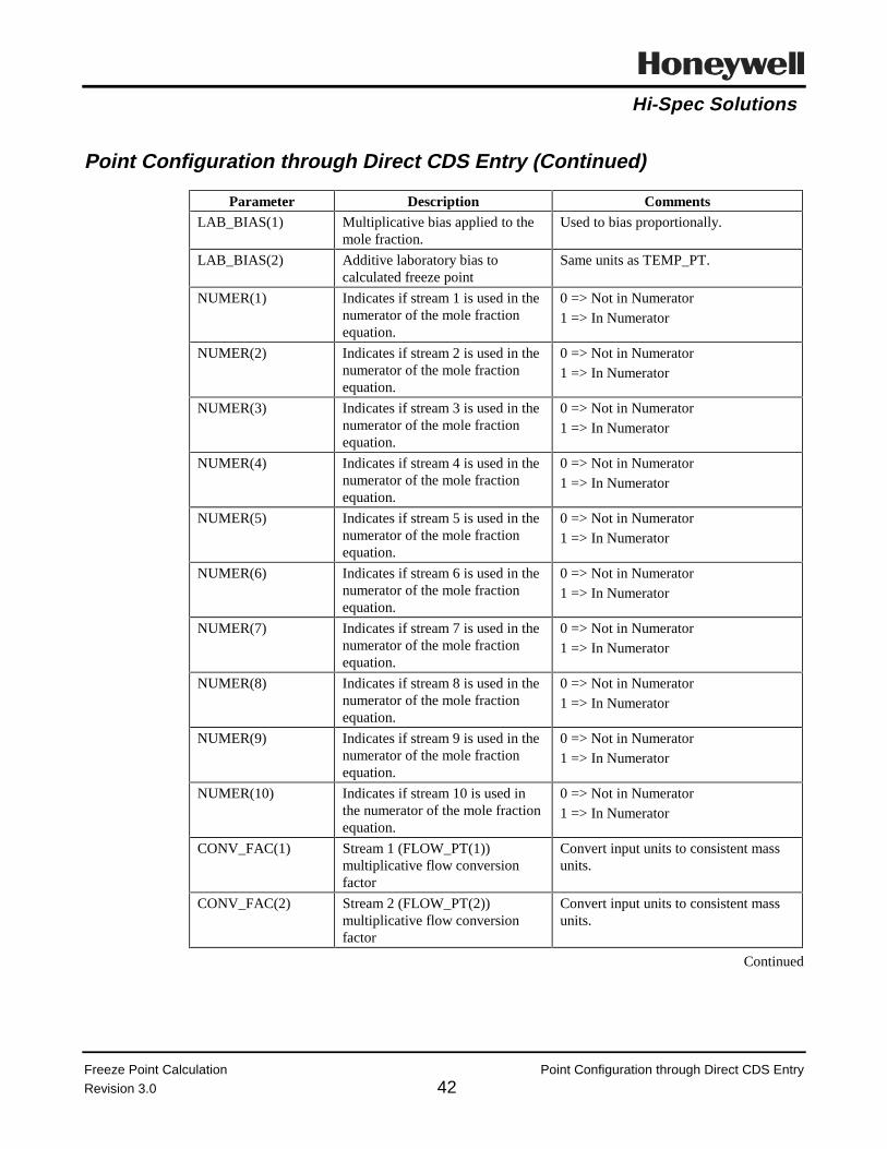
Hi-Spec Solutions
Freeze Point Calculation Point Configuration through Direct CDS Entry
Revision 3.0 42
Point Configuration through Direct CDS Entry (Continued)
Parameter Description CommentsLAB_BIAS(1) Multiplicative bias applied to the
mole fraction.Used to bias proportionally.
LAB_BIAS(2) Additive laboratory bias tocalculated freeze point
Same units as TEMP_PT.
NUMER(1) Indicates if stream 1 is used in thenumerator of the mole fractionequation.
0 => Not in Numerator1 => In Numerator
NUMER(2) Indicates if stream 2 is used in thenumerator of the mole fractionequation.
0 => Not in Numerator1 => In Numerator
NUMER(3) Indicates if stream 3 is used in thenumerator of the mole fractionequation.
0 => Not in Numerator1 => In Numerator
NUMER(4) Indicates if stream 4 is used in thenumerator of the mole fractionequation.
0 => Not in Numerator1 => In Numerator
NUMER(5) Indicates if stream 5 is used in thenumerator of the mole fractionequation.
0 => Not in Numerator1 => In Numerator
NUMER(6) Indicates if stream 6 is used in thenumerator of the mole fractionequation.
0 => Not in Numerator1 => In Numerator
NUMER(7) Indicates if stream 7 is used in thenumerator of the mole fractionequation.
0 => Not in Numerator1 => In Numerator
NUMER(8) Indicates if stream 8 is used in thenumerator of the mole fractionequation.
0 => Not in Numerator1 => In Numerator
NUMER(9) Indicates if stream 9 is used in thenumerator of the mole fractionequation.
0 => Not in Numerator1 => In Numerator
NUMER(10) Indicates if stream 10 is used inthe numerator of the mole fractionequation.
0 => Not in Numerator1 => In Numerator
CONV_FAC(1) Stream 1 (FLOW_PT(1))multiplicative flow conversionfactor
Convert input units to consistent massunits.
CONV_FAC(2) Stream 2 (FLOW_PT(2))multiplicative flow conversionfactor
Convert input units to consistent massunits.
Continued

Hi-Spec Solutions
Freeze Point Calculation Point Configuration through Direct CDS Entry
Revision 3.0 43
Point Configuration through Direct CDS Entry (Continued)
Parameter Description CommentsCONV_FAC(3) Stream 3 (FLOW_PT(3))
multiplicative flow conversionfactor
Convert input units to consistent massunits.
CONV_FAC(4) Stream 4 (FLOW_PT(4))multiplicative flow conversionfactor
Convert input units to consistent massunits.
CONV_FAC(5) Stream 5 (FLOW_PT(5))multiplicative flow conversionfactor
Convert input units to consistent massunits.
CONV_FAC(6) Stream 6 (FLOW_PT(6))multiplicative flow conversionfactor
Convert input units to consistent massunits.
CONV_FAC(7) Stream 7 (FLOW_PT(7))multiplicative flow conversionfactor
Convert input units to consistent massunits.
CONV_FAC(8) Stream 8 (FLOW_PT(8))multiplicative flow conversionfactor
Convert input units to consistent massunits.
CONV_FAC(9) Stream 9 (FLOW_PT(9))multiplicative flow conversionfactor
Convert input units to consistent massunits.
CONV_FAC(10) Stream 10 (FLOW_PT(10))multiplicative flow conversionfactor
Convert input units to consistent massunits.

Hi-Spec Solutions
Freeze Point Calculation Link CL Programs
Revision 2.0 44
Link CL Programs
Step ActionLink FREZ_PNT From the Command Processor Display:
LK $Fn>AO>FREZ_PNT point_name [ENTER]
Activate point Call up the point detail and activate the point, or activate from FREZ_CFGgraphic.
Verify Operation Verify that FREZ_PNT is running without any CL errors.

Hi-Spec Solutions
Freeze Point Calculation Appendix A Engineer’s Detailed Description
Revision 2.0 45

Hi-Spec Solutions
Freeze Point Calculation Appendix A Engineer’s Detailed Description
Revision 2.0 46

Hi-Spec Solutions
Honeywell Hi-Spec Solutions • 16404 N. Black Canyon Hwy. • Phoenix, AZ 85023
Advanced Control Package
Internal Liquid and Vapor Calculation
Controlled
May, 1995Revision 3.0

Hi-Spec Solutions
Internal Liquid and Vapor Calculation Revision History
Revision 3.0

Hi-Spec Solutions
Internal Liquid and Vapor Calculation Contents
Revision 3.0
Table of ContentsOverview.........................................................................................................................................1
Acronym List ..................................................................................................................................3
Hardware and Software Requirements ...........................................................................................4
Instrumentation (Process Inputs) ....................................................................................................5
Process Diagram .............................................................................................................................6
Detailed Description .......................................................................................................................7
Point Structure ..................................................................................................................8
Process Inputs ...................................................................................................................9
Configuration Inputs .......................................................................................................13
Calculation Outputs ........................................................................................................23
Error Codes ...................................................................................................................................28
Diagnostic Location Error Codes....................................................................................29
Diagnostic Error Codes...................................................................................................30
Diagnostic Error Codes (Continued) ..............................................................................33
Configuration and Tuning.............................................................................................................34
Biases in the Internal Liquid and Vapor Calculation......................................................35
Tuning Parameters ..........................................................................................................37
Algorithms ....................................................................................................................................38
Algorithms ......................................................................................................................39
Installation Procedure ...................................................................................................................41
Preparation for Installation ...........................................................................................................42
Custom Data Segment (CDS) and Parameter List (PL) Installation.............................................43
Building Liquid/Vapor Calculation Point.....................................................................................44
Configuration Graphics Installation..............................................................................................45
Configure Calculation Point .........................................................................................................46
Point Configuration Using Graphic LANDVCFG .........................................................47
Point Configuration through Direct CDS Entry..............................................................57
Link CL Programs.........................................................................................................................A1


Hi-Spec Solutions
??
Internal Liquid and Vapor Calculation Overview
Revision 3.0 1
Overview
Definition. Internal liquid and vapor flow rates are the estimated internal mass flowrates of liquid and vapor leaving a tray in a distillation column.
Application. The internal liquid and vapor flow rates are important inputs necessary tocalculate the inferential physical properties (such as, cut point/freeze/pour point) of adistillation column’s product stream and also can be used to estimate floodingconditions.
Calculation. The liquid/vapor calculation program calculates the internal liquid/vaporflows based on:
• Processinputs:
Temperatures, pressures, and flows
• Characterizationinputs:
Watson K and gravity
• Calculatedvalues:
Hydrocarbon stream enthalpies, internal vaporheat, internal net accumulated heat, internalhydrocarbon vapor mass flow, and internal liquidhydrocarbon mass flow.
A heat balance is used to determine the internal liquid flow which allows a materialbalance to be used to determine the internal vapor flow.
Incentive. 1. To provide inputs for inferential property calculations of hydrocarbonproducts.
2. To provide inputs for distillation column flooding calculations.
3. To provide a real-time input for use in advanced control applications.

Hi-Spec Solutions
??
Internal Liquid and Vapor Calculation Overview
Revision 3.0 2
A quick method for estimating the range of the internal liquid flow is to use the closestpumparound or reflux flow above the point in the tower where the internal liquid flow isto be calculated. The range for the internal vapor flow can be estimated by summing upthe overhead product flow, all side product flows and pumparound flows above the traybeing analyzed, and added in the estimated internal liquid flow.
Note: The results of this method are only an approximation of the internal flows andshould evaluated using good engineering judgment and previous experience.

Hi-Spec Solutions
Internal Liquid and Vapor Calculation Acronym List
Revision 3.0 3
Acronym List
Term Acronym
Application Module AM
Local Control Network LCN
Universal Station US
control language CL
process variable PV
custom data segment CDS
pounds per square inch psi
Parameter List PL
CL object code file extension AO
Universal Control Network UCN
thousands of pounds per hour MPPH
pounds per square inch gauge psig

Hi-Spec Solutions
Internal Liquid and Vapor Calculation Hardware and Software Requirements
Revision 3.0 4
Hardware and Software Requirements
Requirement Description
Hardware Platform TDC 3000 AM
Special Boards None
Other Computing Systems None
LCN Release Release 300 or later
AM Load Modules None
US Load Modules None
Other Packages None
Other Control Applications None
Software Inputs Gravities and Watson K factors inputs must exist as points on theLCN

Hi-Spec Solutions
Internal Liquid and Vapor Calculation Instrumentation (Process Inputs)
Revision 3.0 5
Instrumentation (Process Inputs)
Process Input1 Required Recommended
All input stream flow rates X
All input stream temperatures X
Hydrocarbon input stream pressures X
Stripping steam pressure X
1 Required inputs can sometimes be obtained by inference. However, calculations based upon inferred data can be less accurate than calculations based upon direct readings.

Hi-Spec Solutions
Internal Liquid and Vapor Calculation Process Diagram
Revision 3.0 6
Process Diagram
P23
T32
FC3 T52
T4 FC1
FUEL GAS
FC2
T31
FC4
STEAM
KEROSENE
FC5
GAS OIL
FC9
T29 FC8
STEAM
F10
T30
FC7
FC6
STEAM
DIESEL
TOWER
NAPHTHA
F21
T11
STEAM
F11
F22
Envelope 1
RESID.
FEED
F1
T1
Envelope 2

Hi-Spec Solutions
Internal Liquid and Vapor Calculation Detailed Description
Revision 3.0 7
Detailed Description
The tables in this section describe the following liquid/vapor calculation programarchitecture:
• Point Structure
• Process Inputs
• Configuration Inputs
• Calculation Outputs.

Hi-Spec Solutions
Internal Liquid and Vapor Calculation Point Structure
Revision 3.0 8
Point Structure
Point Structure
Point Type AM Regulatory
PV_Type CL
CTL_Type NONE
Custom Data Segment LANDVCDS.CL
Algorithm LANDVGEN.CL
Insertion Point PV_ALG
Slot 5
Output The calculated internal liquid mass flow is displayed as the point’s PV.

Hi-Spec Solutions
Internal Liquid and Vapor Calculation Process Inputs
Revision 3.0 9
Process Inputs
Process Inputs
Critical2
Parameter Description Units Yes No
CALC_PT(1) Tagname for QNET input from anotherenvelope calculation
Mass units *MBTU/Lb
X
CALC_PT(2) Tagname for QNET input from anotherenvelope calculation
Mass units *MBTU/Lb
X
FLOW_PT(1) Tagname for stream 1 flow input Any flow unitsX
FLOW_PT(2) Tagname for stream 2 flow input Any flow unitsX
FLOW_PT(3) Tagname for stream 3 flow input Any flow unitsX
FLOW_PT(4) Tagname for stream 4 flow input Any flow unitsX
FLOW_PT(5) Tagname for stream 5 flow input Any flow unitsX
FLOW_PT(6) Tagname for stream 6 flow input Any flow unitsX
FLOW_PT(7) Tagname for stream 7 flow input Any flow unitsX
FLOW_PT(8) Tagname for stream 8 flow input Any flow unitsX
FLOW_PT(9) Tagname for stream 9 flow input Any flow unitsX
FLOW_PT(10) Tagname for stream 10 flow input Any flow unitsX
FLOW_PT(11) Tagname for stream 11 flow input Any flow unitsX
FLOW_PT(12) Tagname for stream 12 flow input Any flow unitsX
FLOW_PT(13) Tagname for stream 13 flow input Any flow unitsX
FLOW_PT(14) Tagname for stream 14 flow input Any flow unitsX
FLOW_PT(15) Tagname for stream 15 flow input Any flow unitsX
GRAV_PT(1) Tagname for stream 1 gravity °API or S.G.X
GRAV_PT(2) Tagname for stream 2 gravity °API or S.G.X
GRAV_PT(3) Tagname for stream 3 gravity °API or S.G.X
GRAV_PT(4) Tagname for stream 4 gravity °API or S.G.X
GRAV_PT(5) Tagname for stream 5 gravity °API or S.G.X
Continued
2 Critical indicates that a bad input causes the output of the calculation to be set BAD.

Hi-Spec Solutions
Internal Liquid and Vapor Calculation Process Inputs
Revision 3.0 10
Process Inputs (Continued)
Process Inputs
Critical3
Parameter Description Units Yes No
GRAV_PT(6) Tagname for stream 6 gravity °API or S.G.X
GRAV_PT(7) Tagname for stream 7 gravity °API or S.G.X
GRAV_PT(8) Tagname for stream 8 gravity °API or S.G.X
GRAV_PT(9) Tagname for stream 9 gravity °API or S.G.X
GRAV_PT(10) Tagname for stream 10 gravity °API or S.G.X
GRAV_PT(11) Tagname for stream 11 gravity °API or S.G.X
GRAV_PT(12) Tagname for stream 12 gravity °API or S.G.X
GRAV_PT(13) Tagname for stream 13 gravity °API or S.G.X
GRAV_PT(14) Tagname for stream 14 gravity °API or S.G.X
GRAV_PT(15) Tagname for stream 15 gravity °API or S.G.X
GRAV_PT(16) Tagname for internal liquid gravity °API or S.G.X
PRESS_PT(1) Tagname for stream 1 pressure input Any pressure unitsX
PRESS_PT(2) Tagname for stream 2 pressure input Any pressure unitsX
PRESS_PT(3) Tagname for stream 3 pressure input Any pressure unitsX
PRESS_PT(4) Tagname for stream 4 pressure input Any pressure unitsX
PRESS_PT(5) Tagname for stream 5 pressure input Any pressure unitsX
PRESS_PT(6) Tagname for stream 6 pressure input Any pressure unitsX
PRESS_PT(7) Tagname for stream 7 pressure input Any pressure unitsX
PRESS_PT(8) Tagname for stream 8 pressure input Any pressure unitsX
PRESS_PT(9) Tagname for stream 9 pressure input Any pressure unitsX
PRESS_PT(10) Tagname for stream 10 pressure input Any pressure unitsX
PRESS_PT(11) Tagname for stream 11 pressure input Any pressure unitsX
PRESS_PT(12) Tagname for stream 12 pressure input Any pressure unitsX
Continued
3 Critical indicates that a bad input causes the output of the calculation to be set BAD.

Hi-Spec Solutions
Internal Liquid and Vapor Calculation Process Inputs
Revision 3.0 11
Process Inputs (Continued)
Process Inputs
Critical4
Parameter Description Units Yes No
PRESS_PT(13) Tagname for stream 13 pressure input Any pressure unitsX
PRESS_PT(14) Tagname for stream 14 pressure input Any pressure unitsX
PRESS_PT(15) Tagname for stream 15 pressure input Any pressure unitsX
PRESS_PT(16) Tagname of pressure input for internalvapor
Any pressure unitsX
TEMP_PT(1) Tagname for stream 1 temperature input °F or °CX
TEMP_PT(2) Tagname for stream 2 temperature input °F or °CX
TEMP_PT(3) Tagname for stream 3 temperature input °F or °CX
TEMP_PT(4) Tagname for stream 4 temperature input °F or °CX
TEMP_PT(5) Tagname for stream 5 temperature input °F or °CX
TEMP_PT(6) Tagname for stream 6 temperature input °F or °CX
TEMP_PT(7) Tagname for stream 7 temperature input °F or °CX
TEMP_PT(8) Tagname for stream 8 temperature input °F or °CX
TEMP_PT(9) Tagname for stream 9 temperature input °F or °CX
TEMP_PT(10) Tagname for stream 10 temperature input °F or °CX
TEMP_PT(11) Tagname for stream 11 temperature input °F or °CX
TEMP_PT(12) Tagname for stream 12 temperature input °F or °CX
TEMP_PT(13) Tagname for stream 13 temperature input °F or °CX
TEMP_PT(14) Tagname for stream 14 temperature input °F or °CX
TEMP_PT(15) Tagname for stream 15 temperature input °F or °CX
TEMP_PT(16) Tagname for temperature of internal liquidat envelope conditions
°F or °CX
TEMP_PT(17) Tagname for temperature of internal vaporat envelope conditions
°F or °CX
Continued
4 Critical indicates that a bad input causes the output of the calculation to be set BAD.

Hi-Spec Solutions
Internal Liquid and Vapor Calculation Process Inputs
Revision 3.0 12
Process Inputs (Continued)
Process Inputs
Critical5
Parameter Description Units Yes No
WATK_PT(1) Tagname for stream 1 Watson K factor NoneX
WATK_PT(2) Tagname for stream 2 Watson K factor NoneX
WATK_PT(3) Tagname for stream 3 Watson K factor NoneX
WATK_PT(4) Tagname for stream 4 Watson K factor NoneX
WATK_PT(5) Tagname for stream 5 Watson K factor NoneX
WATK_PT(6) Tagname for stream 6 Watson K factor NoneX
WATK_PT(7) Tagname for stream 7 Watson K factor NoneX
WATK_PT(8) Tagname for stream 8 Watson K factor NoneX
WATK_PT(9) Tagname for stream 9 Watson K factor NoneX
WATK_PT(10) Tagname for stream 10 Watson K factor NoneX
WATK_PT(11) Tagname for stream 11 Watson K factor NoneX
WATK_PT(12) Tagname for stream 12 Watson K factor NoneX
WATK_PT(13) Tagname for stream 13 Watson K factor NoneX
WATK_PT(14) Tagname for stream 14 Watson K factor NoneX
WATK_PT(15) Tagname for stream 15 Watson K factor NoneX
WATK_PT(16) Tagname for internal liquid Watson Kfactor
NoneX
.
5 Critical indicates that a bad input causes the output of the calculation to be set BAD.

Hi-Spec Solutions
Internal Liquid and Vapor Calculation Configuration Inputs
Revision 3.0 13
Configuration Inputs
Configuration Inputs
Parameter Description Units
B1(1) Stream 1 gas enthalpy coefficient A N/A
B1(2) Stream 2 gas enthalpy coefficient A N/A
B1(3) Stream 3 gas enthalpy coefficient A N/A
B1(4) Stream 4 gas enthalpy coefficient A N/A
B1(5) Stream 5 gas enthalpy coefficient A N/A
B2(1) Stream 1 gas enthalpy coefficient B N/A
B2(2) Stream 2 gas enthalpy coefficient B N/A
B2(3) Stream 3 gas enthalpy coefficient B N/A
B2(4) Stream 4 gas enthalpy coefficient B N/A
B2(5) Stream 5 gas enthalpy coefficient B N/A
B3(1) Stream 1 gas enthalpy coefficient C N/A
B3(2) Stream 2 gas enthalpy coefficient C N/A
B3(3) Stream 3 gas enthalpy coefficient C N/A
B3(4) Stream 4 gas enthalpy coefficient C N/A
B3(5) Stream 5 gas enthalpy coefficient C N/A
B4(1) Stream 1 gas enthalpy coefficient D N/A
B4(2) Stream 2 gas enthalpy coefficient D N/A
B4(3) Stream 3 gas enthalpy coefficient D N/A
B4(4) Stream 4 gas enthalpy coefficient D N/A
B4(5) Stream 5 gas enthalpy coefficient D N/A
B5(1) Stream 1 gas enthalpy coefficient E N/A
B5(2) Stream 2 gas enthalpy coefficient E N/A
B5(3) Stream 3 gas enthalpy coefficient E N/A
B5(4) Stream 4 gas enthalpy coefficient E N/A
B5(5) Stream 5 gas enthalpy coefficient E N/A
B6(1) Stream 1 gas enthalpy coefficient F N/A
B6(2) Stream 2 gas enthalpy coefficient F N/A
B6(3) Stream 3 gas enthalpy coefficient F N/A
B6(4) Stream 4 gas enthalpy coefficient F N/A
B6(5) Stream 5 gas enthalpy coefficient F N/A
CALC_DIR(1) Indicates if stream 1 is entering or leaving the envelope(-1.0 => entering envelope; 1.0 => leaving envelope)
N/A
CALC_DIR(2) Indicates if stream 2 is entering or leaving the envelope(-1.0 => entering envelope; 1.0 => leaving envelope)
N/A
Continued

Hi-Spec Solutions
Internal Liquid and Vapor Calculation Configuration Inputs
Revision 3.0 14
Configuration Inputs (Continued)
Configuration Inputs
Parameter Description Units
CALC_DIR(3) Indicates if stream 3 is entering or leaving the envelope(-1.0 => entering envelope; 1.0 => leaving envelope)
N/A
CALC_DIR(4) Indicates if stream 4 is entering or leaving the envelope(-1.0 => entering envelope; 1.0 => leaving envelope)
N/A
CALC_DIR(5) Indicates if stream 5 is entering or leaving the envelope(-1.0 => entering envelope; 1.0 => leaving envelope)
N/A
CALC_DIR(6) Indicates if stream 6 is entering or leaving the envelope(-1.0 => entering envelope; 1.0 => leaving envelope)
N/A
CALC_DIR(7) Indicates if stream 7 is entering or leaving the envelope(-1.0 => entering envelope; 1.0 => leaving envelope)
N/A
CALC_DIR(8) Indicates if stream 8 is entering or leaving the envelope(-1.0 => entering envelope; 1.0 => leaving envelope)
N/A
CALC_DIR(9) Indicates if stream 9 is entering or leaving the envelope(-1.0 => entering envelope; 1.0 => leaving envelope)
N/A
CALC_DIR(10) Indicates if stream 10 is entering or leaving the envelope (-1.0 => entering envelope; 1.0 => leaving envelope)
N/A
CALC_DIR(11) Indicates if stream 11 is entering or leaving the envelope (-1.0 => entering envelope; 1.0 => leaving envelope)
N/A
CALC_DIR(12) Indicates if stream 12 is entering or leaving the envelope (-1.0 => entering envelope; 1.0 => leaving envelope)
N/A
CALC_DIR(13) Indicates if stream 13 is entering or leaving the envelope (-1.0 => entering envelope; 1.0 => leaving envelope)
N/A
CALC_DIR(14) Indicates if stream 14 is entering or leaving the envelope (-1.0 => entering envelope; 1.0 => leaving envelope)
N/A
CALC_DIR(15) Indicates if stream 15 is entering or leaving the envelope (-1.0 => entering envelope; 1.0 => leaving envelope)
N/A
CALC_DIR(16) Indicates if calculated internal liquid is entering or leavingthe envelope (-1.0 => entering envelope; 1.0 => leavingenvelope)
N/A
CALC_DIR(17) Indicates calculation direction (-1.0 => from bottom up;1.0 => from top down)
N/A
CONV_FAC(1) Stream 1 multiplicative flow conversion factor From input unitsto MPPH
CONV_FAC(2) Stream 2 multiplicative flow conversion factor From input unitsto MPPH
CONV_FAC(3) Stream 3 multiplicative flow conversion factor From input unitsto MPPH
CONV_FAC(4) Stream 4 multiplicative flow conversion factor From input unitsto MPPH
Continued

Hi-Spec Solutions
Internal Liquid and Vapor Calculation Configuration Inputs
Revision 3.0 15
Configuration Inputs (Continued)
Configuration Inputs
Parameter Description Units
CONV_FAC(5) Stream 5 multiplicative flow conversion factor From input unitsto MPPH
CONV_FAC(6) Stream 6 multiplicative flow conversion factor From input unitsto MPPH
CONV_FAC(7) Stream 7 multiplicative flow conversion factor From input unitsto MPPH
CONV_FAC(8) Stream 8 multiplicative flow conversion factor From input unitsto MPPH
CONV_FAC(9) Stream 9 multiplicative flow conversion factor From input unitsto MPPH
CONV_FAC(10) Stream 10 multiplicative flow conversion factor From input unitsto MPPH
CONV_FAC(11) Stream 11 multiplicative flow conversion factor From input unitsto MPPH
CONV_FAC(12) Stream 12 multiplicative flow conversion factor From input unitsto MPPH
CONV_FAC(13) Stream 13 multiplicative flow conversion factor From input unitsto MPPH
CONV_FAC(14) Stream 14 multiplicative flow conversion factor From input unitsto MPPH
CONV_FAC(15) Stream 15 multiplicative flow conversion factor From input unitsto MPPH
CONV_FAC(16) Input temperature unit flag; 0 => °F; 1 => °C
N/A
CONV_FAC(17) Pressure multiplicative conversion factor From input unitsto psig
CONV_FAC(18) Input gravity type flag :0 => API; 1 => Specific gravity
N/A
CONV_FAC(19) Conversion factor for calculated internal liquid mass flow From MPPH todesired units
ENGPAR(1) Number of input flow streams (0.0 < ENGPAR(1) <=15.0)
N/A
ENGPAR(2) Local atmospheric pressure (a value of 14.696 will be usedinternally if a zero is entered)
Same units asPRESS_PT
ENGPAR(3) Envelope heat loss MBTU/Lb *Mass Units
Continued

Hi-Spec Solutions
Internal Liquid and Vapor Calculation Configuration Inputs
Revision 3.0 16
Configuration Inputs (Continued)
Configuration Inputs
Parameter Description Units
ENGPAR(4) Flag to force calculation BAD(0 => Do not set BAD; 1 => Set calculation BAD)
N/A
ENGPAR(5) Not used N/A
ENGPAR(6) Not used N/A
ENGPAR(7) Not used N/A
ENGPAR(8) Not used N/A
ENGPAR(9) Not used N/A
ENGPAR(10) Not used N/A
FILTER(1) Stream 1 flow input filter time Minutes
FILTER(2) Stream 2 flow input filter time Minutes
FILTER(3) Stream 3 flow input filter time Minutes
FILTER(4) Stream 4 flow input filter time Minutes
FILTER(5) Stream 5 flow input filter time Minutes
FILTER(6) Stream 6 flow input filter time Minutes
FILTER(7) Stream 7 flow input filter time Minutes
FILTER(8) Stream 8 flow input filter time Minutes
FILTER(9) Stream 9 flow input filter time Minutes
FILTER(10) Stream 10 flow input filter time Minutes
FILTER(11) Stream 11 flow input filter time Minutes
FILTER(12) Stream 12 flow input filter time Minutes
FILTER(13) Stream 13 flow input filter time Minutes
FILTER(14) Stream 14 flow input filter time Minutes
FILTER(15) Stream 15 flow input filter time Minutes
FILTER(16) Stream 1 temperature input filter time Minutes
FILTER(17) Stream 2 temperature input filter time Minutes
FILTER(18) Stream 3 temperature input filter time Minutes
FILTER(19) Stream 4 temperature input filter time Minutes
FILTER(20) Stream 5 temperature input filter time Minutes
FILTER(21) Stream 6 temperature input filter time Minutes
FILTER(22) Stream 7 temperature input filter time Minutes
FILTER(23) Stream 8 temperature input filter time Minutes
FILTER(24) Stream 9 temperature input filter time Minutes
FILTER(25) Stream 10 temperature input filter time Minutes
FILTER(26) Stream 11 temperature input filter time Minutes
Continued

Hi-Spec Solutions
Internal Liquid and Vapor Calculation Configuration Inputs
Revision 3.0 17
Configuration Inputs (Continued)
Configuration Inputs
Parameter Description Units
FILTER(27) Stream 12 temperature input filter time Minutes
FILTER(28) Stream 13 temperature input filter time Minutes
FILTER(29) Stream 14 temperature input filter time Minutes
FILTER(30) Stream 15 temperature input filter time Minutes
FILTER(31) Internal liquid temperature input filter time Minutes
FILTER(32) Internal vapor temperature input filter time Minutes
FILTER(33) Stream 1 pressure input filter time Minutes
FILTER(34) Stream 2 pressure input filter time Minutes
FILTER(35) Stream 3 pressure input filter time Minutes
FILTER(36) Stream 4 pressure input filter time Minutes
FILTER(37) Stream 5 pressure input filter time Minutes
FILTER(38) Stream 6 pressure input filter time Minutes
FILTER(39) Stream 7 pressure input filter time Minutes
FILTER(40) Stream 8 pressure input filter time Minutes
FILTER(41) Stream 9 pressure input filter time Minutes
FILTER(42) Stream 10 pressure input filter time Minutes
FILTER(43) Stream 11 pressure input filter time Minutes
FILTER(44) Stream 12 pressure input filter time Minutes
FILTER(45) Stream 13 pressure input filter time Minutes
FILTER(46) Stream 14 pressure input filter time Minutes
FILTER(47) Stream 15 pressure input filter time Minutes
FILTER(48) Internal vapor pressure input filter time Minutes
FILTER(49) Stream 1 gravity input filter time Minutes
FILTER(50) Stream 2 gravity input filter time Minutes
FILTER(51) Stream 3 gravity input filter time Minutes
FILTER(52) Stream 4 gravity input filter time Minutes
FILTER(53) Stream 5 gravity input filter time Minutes
FILTER(54) Stream 6 gravity input filter time Minutes
FILTER(55) Stream 7 gravity input filter time Minutes
FILTER(56) Stream 8 gravity input filter time Minutes
FILTER(57) Stream 9 gravity input filter time Minutes
FILTER(58) Stream 10 gravity input filter time Minutes
FILTER(59) Stream 11 gravity input filter time Minutes
FILTER(60) Stream 12 gravity input filter time Minutes
FILTER(61) Stream 13 gravity input filter time Minutes
Continued

Hi-Spec Solutions
Internal Liquid and Vapor Calculation Configuration Inputs
Revision 3.0 18
Configuration Inputs (Continued)
Configuration Inputs
Parameter Description Units
FILTER(62) Stream 14 gravity input filter time Minutes
FILTER(63) Stream 15 gravity input filter time Minutes
FILTER(64) Internal liquid gravity input filter time Minutes
FILTER(65) Stream 1 Watson K input filter time Minutes
FILTER(66) Stream 2 Watson K input filter time Minutes
FILTER(67) Stream 3 Watson K input filter time Minutes
FILTER(68) Stream 4 Watson K input filter time Minutes
FILTER(69) Stream 5 Watson K input filter time Minutes
FILTER(70) Stream 6 Watson K input filter time Minutes
FILTER(71) Stream 7 Watson K input filter time Minutes
FILTER(72) Stream 8 Watson K input filter time Minutes
FILTER(73) Stream 9 Watson K input filter time Minutes
FILTER(74) Stream 10 Watson K input filter time Minutes
FILTER(75) Stream 11 Watson K input filter time Minutes
FILTER(76) Stream 12 Watson K input filter time Minutes
FILTER(77) Stream 13 Watson K input filter time Minutes
FILTER(78) Stream 14 Watson K input filter time Minutes
FILTER(79) Stream 15 Watson K input filter time Minutes
FILTER(80) Internal liquid Watson K input filter time Minutes
FILTER(81) Filter time for QNET input from another envelopecalculation
Minutes
FILTER(82) Stream 1 calculated dynamic heat effect filter time Minutes
FILTER(83) Stream 2 calculated dynamic heat effect filter time Minutes
FILTER(84) Stream 3 calculated dynamic heat effect filter time Minutes
FILTER(85) Stream 4 calculated dynamic heat effect filter time Minutes
FILTER(86) Stream 5 calculated dynamic heat effect filter time Minutes
FILTER(87) Stream 6 calculated dynamic heat effect filter time Minutes
FILTER(88) Stream 7 calculated dynamic heat effect filter time Minutes
FILTER(89) Stream 8 calculated dynamic heat effect filter time Minutes
FILTER(90) Stream 9 calculated dynamic heat effect filter time Minutes
FILTER(91) Stream 10 calculated dynamic heat effect filter time Minutes
FILTER(92) Stream 11 calculated dynamic heat effect filter time Minutes
FILTER(93) Stream 12 calculated dynamic heat effect filter time Minutes
FILTER(94) Stream 13 calculated dynamic heat effect filter time Minutes
Continued

Hi-Spec Solutions
Internal Liquid and Vapor Calculation Configuration Inputs
Revision 3.0 19
Configuration Inputs (Continued)
Configuration Inputs
Parameter Description Units
FILTER(95) Stream 14 calculated dynamic heat effect filter time Minutes
FILTER(96) Stream 15 calculated dynamic heat effect filter time Minutes
P_BIAS(1) Stream 1 pressure input additive bias Same asPRESS_PT(1)
P_BIAS(2) Stream 2 pressure input additive bias Same asPRESS_PT(2)
P_BIAS(3) Stream 3 pressure input additive bias Same asPRESS_PT(3)
P_BIAS(4) Stream 4 pressure input additive bias Same asPRESS_PT(4)
P_BIAS(5) Stream 5 pressure input additive bias Same asPRESS_PT(5)
P_BIAS(6) Stream 6 pressure input additive bias Same asPRESS_PT(6)
P_BIAS(7) Stream 7 pressure input additive bias Same asPRESS_PT(7)
P_BIAS(8) Stream 8 pressure input additive bias Same asPRESS_PT(8)
P_BIAS(9) Stream 9 pressure input additive bias Same asPRESS_PT(9)
P_BIAS(10) Stream 10 pressure input additive bias Same asPRESS_PT(10)
P_BIAS(11) Stream 11 pressure input additive bias Same asPRESS_PT(11)
P_BIAS(12) Stream 12 pressure input additive bias Same asPRESS_PT(12)
P_BIAS(13) Stream 13 pressure input additive bias Same asPRESS_PT(13)
P_BIAS(14) Stream 14 pressure input additive bias Same asPRESS_PT(14)
P_BIAS(15) Stream 15 pressure input additive bias Same asPRESS_PT(15)
P_BIAS(16) Internal vapor pressure input additive bias Same asPRESS_PT(16)
QTYPE(1) Stream 1 type for QNET calculation (0 => None;1 => Gas; 2 => Vapor; 3 => Liquid; 4 => Steam)
N/A
QTYPE(2) Stream 2 type for QNET calculation (0 => None;1 => Gas; 2 => Vapor; 3 => Liquid; 4 => Steam)
N/A
Continued

Hi-Spec Solutions
Internal Liquid and Vapor Calculation Configuration Inputs
Revision 3.0 20
Configuration Inputs (Continued)
Configuration Inputs
Parameter Description Units
QTYPE(3) Stream 3 type for QNET calculation (0 => None;1 => Gas; 2 => Vapor; 3 => Liquid; 4 => Steam)
N/A
QTYPE(4) Stream 4 type for QNET calculation (0 => None;1 => Gas; 2 => Vapor; 3 => Liquid; 4 => Steam)
N/A
QTYPE(5) Stream 5 type for QNET calculation (0 => None;1 => Gas; 2 => Vapor; 3 => Liquid; 4 => Steam)
N/A
QTYPE(6) Stream 6 type for QNET calculation (0 => None;1 => Gas; 2 => Vapor; 3 => Liquid; 4 => Steam)
N/A
QTYPE(7) Stream 7 type for QNET calculation (0 => None;1 => Gas; 2 => Vapor; 3 => Liquid; 4 => Steam)
N/A
QTYPE(8) Stream 8 type for QNET calculation (0 => None;1 => Gas; 2 => Vapor; 3 => Liquid; 4 => Steam)
N/A
QTYPE(9) Stream 9 type for QNET calculation (0 => None;1 => Gas; 2 => Vapor; 3 => Liquid; 4 => Steam)
N/A
QTYPE(10) Stream 10 type for QNET calculation (0 => None;1 => Gas; 2 => Vapor; 3 => Liquid; 4 => Steam)
N/A
QTYPE(11) Stream 11 type for QNET calculation (0 => None;1 => Gas; 2 => Vapor; 3 => Liquid; 4 => Steam)
N/A
QTYPE(12) Stream 12 type for QNET calculation (0 => None;1 => Gas; 2 => Vapor; 3 => Liquid; 4 => Steam)
N/A
QTYPE(13) Stream 13 type for QNET calculation (0 => None;1 => Gas; 2 => Vapor; 3 => Liquid; 4 => Steam)
N/A
QTYPE(14) Stream 14 type for QNET calculation (0 => None;1 => Gas; 2 => Vapor; 3 => Liquid; 4 => Steam)
N/A
QTYPE(15) Stream 15 type for QNET calculation (0 => None;1 => Gas; 2 => Vapor; 3 => Liquid; 4 => Steam)
N/A
QTYPE(16) Internal liquid type for QNET calculation (0 => None;1 => Gas; 2 => Vapor; 3 => Liquid; 4 => Steam)
N/A
T_BIAS(1) Stream 1 temperature input additive bias Same asTEMP_PT(1)
T_BIAS(2) Stream 2 temperature input additive bias Same asTEMP_PT(2)
T_BIAS(3) Stream 3 temperature input additive bias Same asTEMP_PT(3)
T_BIAS(4) Stream 4 temperature input additive bias Same asTEMP_PT(4)
T_BIAS(5) Stream 5 temperature input additive bias Same asTEMP_PT(5)
Continued

Hi-Spec Solutions
Internal Liquid and Vapor Calculation Configuration Inputs
Revision 3.0 21
Configuration Inputs (Continued)
Configuration Inputs
Parameter Description Units
T_BIAS(6) Stream 6 temperature input additive bias Same asTEMP_PT(6)
T_BIAS(7) Stream 7 temperature input additive bias Same asTEMP_PT(7)
T_BIAS(8) Stream 8 temperature input additive bias Same asTEMP_PT(8)
T_BIAS(9) Stream 9 temperature input additive bias Same asTEMP_PT(9)
T_BIAS(10) Stream 10 temperature input additive bias Same asTEMP_PT(10)
T_BIAS(11) Stream 11 temperature input additive bias Same asTEMP_PT(11)
T_BIAS(12) Stream 12 temperature input additive bias Same asTEMP_PT(12)
T_BIAS(13) Stream 13 temperature input additive bias Same asTEMP_PT(13)
T_BIAS(14) Stream 14 temperature input additive bias Same asTEMP_PT(14)
T_BIAS(15) Stream 15 temperature input additive bias Same asTEMP_PT(15)
T_BIAS(16) Internal liquid temperature additive bias Same asTEMP_PT(16)
T_BIAS(17) Internal vapor temperature additive bias Same asTEMP_PT(17)
VTYPE(1) Stream 1 type for QVAP calculation (0 => None;1 => Gas; 2 => Vapor; 3 => Liquid; 4 => Steam)
N/A
VTYPE(2) Stream 2 type for QVAP calculation (0 => None;1 => Gas; 2 => Vapor; 3 => Liquid; 4 => Steam)
N/A
VTYPE(3) Stream 3 type for QVAP calculation (0 => None;1 => Gas; 2 => Vapor; 3 => Liquid; 4 => Steam)
N/A
VTYPE(4) Stream 4 type for QVAP calculation (0 => None;1 => Gas; 2 => Vapor; 3 => Liquid; 4 => Steam)
N/A
VTYPE(5) Stream 5 type for QVAP calculation (0 => None;1 => Gas; 2 => Vapor; 3 => Liquid; 4 => Steam)
N/A
VTYPE(6) Stream 6 type for QVAP calculation (0 => None;1 => Gas; 2 => Vapor; 3 => Liquid; 4 => Steam)
N/A
VTYPE(7) Stream 7 type for QVAP calculation (0 => None;1 => Gas; 2 => Vapor; 3 => Liquid; 4 => Steam)
N/A
Continued

Hi-Spec Solutions
Internal Liquid and Vapor Calculation Configuration Inputs
Revision 3.0 22
Configuration Inputs (Continued)
Configuration Inputs
Parameter Description Units
VTYPE(8) Stream 8 type for QVAP calculation (0 => None;1 => Gas; 2 => Vapor; 3 => Liquid; 4 => Steam)
N/A
VTYPE(9) Stream 9 type for QVAP calculation (0 => None;1 => Gas; 2 => Vapor; 3 => Liquid; 4 => Steam)
N/A
VTYPE(10) Stream 10 type for QVAP calculation (0 => None;1 => Gas; 2 => Vapor; 3 => Liquid; 4 => Steam)
N/A
VTYPE(11) Stream 11 type for QVAP calculation (0 => None;1 => Gas; 2 => Vapor; 3 => Liquid; 4 => Steam)
N/A
VTYPE(12) Stream 12 type for QVAP calculation (0 => None;1 => Gas; 2 => Vapor; 3 => Liquid; 4 => Steam)
N/A
VTYPE(13) Stream 13 type for QVAP calculation (0 => None;1 => Gas; 2 => Vapor; 3 => Liquid; 4 => Steam)
N/A
VTYPE(14) Stream 14 type for QVAP calculation (0 => None;1 => Gas; 2 => Vapor; 3 => Liquid; 4 => Steam)
N/A
VTYPE(15) Stream 15 type for QVAP calculation (0 => None;1 => Gas; 2 => Vapor; 3 => Liquid; 4 => Steam)
N/A
VTYPE(16) Internal liquid type for QVAP calculation (0 => None;1 => Gas; 2 => Vapor; 3 => Liquid; 4 => Steam)
N/A

Hi-Spec Solutions
Internal Liquid and Vapor Calculation Calculation Outputs
Revision 3.0 23
Calculation Outputs
Calculation Outputs
Parameter Description Units
CALC_VAL(1) Calculated internal liquid flow rate Mass units
CALC_VAL(2) Calculated internal vapor flow rate Mass units
CALC_VAL(3) Difference between the internal vapor flow and the internalliquid flow
Mass units
CALC_VAL(4) Calculated QNET value MBTU/Lb * Massunits
CALC_VAL(5) Calculated QVAP value MBTU/Lb * Massunits
FILT_VAL(1) Stream 1 flow input filtered value Input units
FILT_VAL(2) Stream 2 flow input filtered value Input units
FILT_VAL(3) Stream 3 flow input filtered value Input units
FILT_VAL(4) Stream 4 flow input filtered value Input units
FILT_VAL(5) Stream 5 flow input filtered value Input units
FILT_VAL(6) Stream 6 flow input filtered value Input units
FILT_VAL(7) Stream 7 flow input filtered value Input units
FILT_VAL(8) Stream 8 flow input filtered value Input units
FILT_VAL(9) Stream 9 flow input filtered value Input units
FILT_VAL(10) Stream 10 flow input filtered value Input units
FILT_VAL(11) Stream 11 flow input filtered value Input units
FILT_VAL(12) Stream 12 flow input filtered value Input units
FILT_VAL(13) Stream 13 flow input filtered value None
FILT_VAL(14) Stream 14 flow input filtered value None
FILT_VAL(15) Stream 15 flow input filtered value Input units
FILT_VAL(16) Stream 1 temperature input filtered value Input units
FILT_VAL(17) Stream 2 temperature input filtered value Input units
FILT_VAL(18) Stream 3 temperature input filtered value Input units
FILT_VAL(19) Stream 4 temperature input filtered value Input units
FILT_VAL(20) Stream 5 temperature input filtered value Input units
FILT_VAL(21) Stream 6 temperature input filtered value Input units
FILT_VAL(22) Stream 7 temperature input filtered value Input units
FILT_VAL(23) Stream 8 temperature input filtered value Input units
FILT_VAL(24) Stream 9 temperature input filtered value Input units
FILT_VAL(25) Stream 10 temperature input filtered value Input units
FILT_VAL(26) Stream 11 temperature input filtered value Input units
FILT_VAL(27) Stream 12 temperature input filtered value Input units
Continued

Hi-Spec Solutions
Internal Liquid and Vapor Calculation Calculation Outputs
Revision 3.0 24
Calculation Outputs (Continued)
Calculation Outputs
Parameter Description Units
FILT_VAL(28) Stream 13 temperature input filtered value Input units
FILT_VAL(29) Stream 14 temperature input filtered value Input units
FILT_VAL(30) Stream 15 temperature input filtered value Input units
FILT_VAL(31) Internal liquid temperature input filtered value Input units
FILT_VAL(32) Internal vapor temperature input filtered value Input units
FILT_VAL(33) Stream 1 pressure input filtered value Input units
FILT_VAL(34) Stream 2 pressure input filtered value Input units
FILT_VAL(35) Stream 3 pressure input filtered value Input units
FILT_VAL(36) Stream 4 pressure input filtered value Input units
FILT_VAL(37) Stream 5 pressure input filtered value Input units
FILT_VAL(38) Stream 6 pressure input filtered value Input units
FILT_VAL(39) Stream 7 pressure input filtered value Input units
FILT_VAL(40) Stream 8 pressure input filtered value Input units
FILT_VAL(41) Stream 9 pressure input filtered value Input units
FILT_VAL(42) Stream 10 pressure input filtered value Input units
FILT_VAL(43) Stream 11 pressure input filtered value Input units
FILT_VAL(44) Stream 12 pressure input filtered value Input units
FILT_VAL(45) Stream 13 pressure input filtered value Input units
FILT_VAL(46) Stream 14 pressure input filtered value Input units
FILT_VAL(47) Stream 15 pressure input filtered value Input units
FILT_VAL(48) Internal vapor pressure input filtered value Input units
FILT_VAL(49) Stream 1 gravity input filtered value Input units
FILT_VAL(50) Stream 2 gravity input filtered value Input units
FILT_VAL(51) Stream 3 gravity input filtered value Input units
FILT_VAL(52) Stream 4 gravity input filtered value Input units
FILT_VAL(53) Stream 5 gravity input filtered value Input units
FILT_VAL(54) Stream 6 gravity input filtered value Input units
FILT_VAL(55) Stream 7 gravity input filtered value Input units
FILT_VAL(56) Stream 8 gravity input filtered value Input units
FILT_VAL(57) Stream 9 gravity input filtered value Input units
FILT_VAL(58) Stream 10 gravity input filtered value Input units
FILT_VAL(59) Stream 11 gravity input filtered value Input units
FILT_VAL(60) Stream 12 gravity input filtered value Input units
FILT_VAL(61) Stream 13 gravity input filtered value Input units
FILT_VAL(62) Stream 14 gravity input filtered value Input units
Continued

Hi-Spec Solutions
Internal Liquid and Vapor Calculation Calculation Outputs
Revision 3.0 25
Calculation Outputs (Continued)
Calculation Outputs
Parameter Description Units
FILT_VAL(63) Stream 15 gravity input filtered value Input units
FILT_VAL(64) Internal liquid gravity input filtered value Input units
FILT_VAL(65) Stream 1 Watson K input filtered value N/A
FILT_VAL(66) Stream 2 Watson K input filtered value N/A
FILT_VAL(67) Stream 3 Watson K input filtered value N/A
FILT_VAL(68) Stream 4 Watson K input filtered value N/A
FILT_VAL(69) Stream 5 Watson K input filtered value N/A
FILT_VAL(70) Stream 6 Watson K input filtered value N/A
FILT_VAL(71) Stream 7 Watson K input filtered value N/A
FILT_VAL(72) Stream 8 Watson K input filtered value N/A
FILT_VAL(73) Stream 9 Watson K input filtered value N/A
FILT_VAL(74) Stream 10 Watson K input filtered value N/A
FILT_VAL(75) Stream 11 Watson K input filtered value N/A
FILT_VAL(76) Stream 12 Watson K input filtered value N/A
FILT_VAL(77) Stream 13 Watson K input filtered value N/A
FILT_VAL(78) Stream 14 Watson K input filtered value N/A
FILT_VAL(79) Stream 15 Watson K input filtered value N/A
FILT_VAL(80) Internal liquid Watson K input filtered value N/A
FILT_VAL(81) QNET input from another envelope calculation filteredvalue
MBTU/Lb * Massunits
FILT_VAL(82) Stream 1 calculated dynamic heat effect filtered value MBTU/Lb * Massunits
FILT_VAL(83) Stream 2 calculated dynamic heat effect filtered value MBTU/Lb * Massunits
FILT_VAL(84) Stream 3 calculated dynamic heat effect filtered value MBTU/Lb * Massunits
FILT_VAL(85) Stream 4 calculated dynamic heat effect filtered value MBTU/Lb * Massunits
FILT_VAL(86) Stream 5 calculated dynamic heat effect filtered value MBTU/Lb * Massunits
FILT_VAL(87) Stream 6 calculated dynamic heat effect filtered value MBTU/Lb * Massunits
FILT_VAL(88) Stream 7 calculated dynamic heat effect filtered value MBTU/Lb * Massunits
FILT_VAL(89) Stream 8 calculated dynamic heat effect filtered value MBTU/Lb * Massunits
Continued

Hi-Spec Solutions
Internal Liquid and Vapor Calculation Calculation Outputs
Revision 3.0 26
Calculation Outputs (Continued)
Calculation Outputs
Parameter Description Units
FILT_VAL(90) Stream 9 calculated dynamic heat effect filtered value MBTU/Lb * Massunits
FILT_VAL(91) Stream 10 calculated dynamic heat effect filtered value MBTU/Lb * Massunits
FILT_VAL(92) Stream 11 calculated dynamic heat effect filtered value MBTU/Lb * Massunits
FILT_VAL(93) Stream 12 calculated dynamic heat effect filtered value MBTU/Lb * Massunits
FILT_VAL(94) Stream 13 calculated dynamic heat effect filtered value MBTU/Lb * Massunits
FILT_VAL(95) Stream 14 calculated dynamic heat effect filtered value MBTU/Lb * Massunits
FILT_VAL(96) Stream 15 calculated dynamic heat effect filtered value MBTU/Lb * Massunits
PVCALC Calculated internal liquid flow rate User Defined
QNETENTH(1) Stream 1 calculated enthalpy for QNET MBTU/Lb
QNETENTH(2) Stream 2 calculated enthalpy for QNET MBTU/Lb
QNETENTH(3) Stream 3 calculated enthalpy for QNET MBTU/Lb
QNETENTH(4) Stream 4 calculated enthalpy for QNET MBTU/Lb
QNETENTH(5) Stream 5 calculated enthalpy for QNET MBTU/Lb
QNETENTH(6) Stream 6 calculated enthalpy for QNET MBTU/Lb
QNETENTH(7) Stream 7 calculated enthalpy for QNET MBTU/Lb
QNETENTH(8) Stream 8 calculated enthalpy for QNET MBTU/Lb
QNETENTH(9) Stream 9 calculated enthalpy for QNET MBTU/Lb
QNETENTH(10) Stream 10 calculated enthalpy for QNET MBTU/Lb
QNETENTH(11) Stream 11 calculated enthalpy for QNET MBTU/Lb
QNETENTH(12) Stream 12 calculated enthalpy for QNET MBTU/Lb
QNETENTH(13) Stream 13 calculated enthalpy for QNET MBTU/Lb
QNETENTH(14) Stream 14 calculated enthalpy for QNET MBTU/Lb
QNETENTH(15) Stream 15 calculated enthalpy for QNET MBTU/Lb
QNETENTH(16) Internal liquid calculated enthalpy for QNET MBTU/Lb
QVAPENTH(1) Stream 1 calculated enthalpy for QVAP MBTU/Lb
QVAPENTH(2) Stream 2 calculated enthalpy for QVAP MBTU/Lb
QVAPENTH(3) Stream 3 calculated enthalpy for QVAP MBTU/Lb
QVAPENTH(4) Stream 4 calculated enthalpy for QVAP MBTU/Lb
QVAPENTH(5) Stream 5 calculated enthalpy for QVAP MBTU/Lb
Continued

Hi-Spec Solutions
Internal Liquid and Vapor Calculation Calculation Outputs
Revision 3.0 27
Calculation Outputs (Continued)
Calculation Outputs
Parameter Description Units
QVAPENTH(6) Stream 6 calculated enthalpy for QVAP MBTU/Lb
QVAPENTH(7) Stream 7 calculated enthalpy for QVAP MBTU/Lb
QVAPENTH(8) Stream 8 calculated enthalpy for QVAP MBTU/Lb
QVAPENTH(9) Stream 9 calculated enthalpy for QVAP MBTU/Lb
QVAPENTH(10) Stream 10 calculated enthalpy for QVAP MBTU/Lb
QVAPENTH(11) Stream 11 calculated enthalpy for QVAP MBTU/Lb
QVAPENTH(12) Stream 12 calculated enthalpy for QVAP MBTU/Lb
QVAPENTH(13) Stream 13 calculated enthalpy for QVAP MBTU/Lb
QVAPENTH(14) Stream 14 calculated enthalpy for QVAP MBTU/Lb
QVAPENTH(15) Stream 15 calculated enthalpy for QVAP MBTU/Lb
QVAPENTH(16) Internal liquid calculated enthalpy for QVAP MBTU/Lb
REV_NO Program revision number N/A
STATUS(1) Diagnostic indication of location and possible causes ofprogram error
N/A
STATUS(2) Diagnostic indication of subroutine error N/A

Hi-Spec Solutions
Internal Liquid and Vapor Calculation Error Codes
Revision 3.0 28
Error Codes
The tables in this section describe the following program error codes:
• Diagnostic location error codes
• Diagnostic error codes.

Hi-Spec Solutions
Internal Liquid and Vapor Calculation Diagnostic Location Error Codes
Revision 2.01 29
Diagnostic Location Error Codes
Diagnostic Location Error Codes
Parameter Value Meaning
STATUS(1)6 0.0 No errors
1.0 Stream 1 has an error (see STATUS(2) "Diagnostic Error Codes")
2.0 Stream 2 has an error (see STATUS(2) "Diagnostic Error Codes")
3.0 Stream 3 has an error (see STATUS(2) "Diagnostic Error Codes")
4.0 Stream 4 has an error (see STATUS(2) "Diagnostic Error Codes")
5.0 Stream 5 has an error (see STATUS(2) "Diagnostic Error Codes")
6.0 Stream 6 has an error (see STATUS(2) "Diagnostic Error Codes")
7.0 Stream 7 has an error (see STATUS(2) "Diagnostic Error Codes")
8.0 Stream 8 has an error (see STATUS(2) "Diagnostic Error Codes")
9.0 Stream 9 has an error (see STATUS(2) "Diagnostic Error Codes")
10.0 Stream 10 has an error (see STATUS(2) "Diagnostic ErrorCodes")
11.0 Stream 11 has an error (see STATUS(2) "Diagnostic ErrorCodes")
12.0 Stream 12 has an error (see STATUS(2) "Diagnostic ErrorCodes")
13.0 Stream 13 has an error (see STATUS(2) "Diagnostic ErrorCodes")
14.0 Stream 14 has an error (see STATUS(2) "Diagnostic ErrorCodes")
STATUS(1)3 15.0 Stream 15 has an error (see STATUS(2) "Diagnostic ErrorCodes")
16.0 Internal vapor pressure input or an internal liquid input has anerror (see STATUS(2) "Diagnostic Error Codes")
17.0 Internal vapor temperature input has an error (see STATUS(2)"Diagnostic Error Codes")
6 STATUS(1) indicates the location of any errors in the calculation.3 STATUS(1) indicates the location of any errors in the calculation.

Hi-Spec Solutions
Internal Liquid and Vapor Calculation Diagnostic Error Codes
Revision 3.0 30
Diagnostic Error Codes
Diagnostic Error Codes
Parameter Value Meaning
STATUS(2)7 -2.0 The steam input temperature is below the steam saturationtemperature
0.0 No errors
1.0 Set calculation BAD flag is on
2.0 Input number of streams is greater than 15.0
3.0 Externally QNET input has a bad PV
4.0 A flow input (FLOW_PT(i)) has a null point entered or has a badPV
5.0 A temperature input (TEMP_PT(i)) has a null point entered or hasa bad PV
6.0 A pressure input (PRESS_PT(i)) has a null point entered or has abad PV
7.0 A gravity input (GRAV_PT(i)) has a null point entered or has abad PV
8.0 A Watson K factor input (WATK_PT(i)) has a null point enteredor has a bad PV
9.0 A QNET input does not have a configured type (steam, gas,vapor, liquid)
10.0 A QVAP input does not have a configured type (steam, gas,vapor, liquid)
11.0 A configured type gas in not one of the first 5 inputs
STATUS(2)4 101 Stream is of type gas for QNET calculation and the calculatedenthalpy has a bad value
102 Stream is of type gas for QNET calculation and the temperatureinput has a bad value
103 Stream is of type gas for QNET calculation and the enthalpycoefficient A input has a bad value
104 Stream is of type gas for QNET calculation and the enthalpycoefficient B input has a bad value
105 Stream is of type gas for QNET calculation and the enthalpycoefficient C input has a bad value
106 Stream is of type gas for QNET calculation and the enthalpycoefficient D input has a bad value
107 Stream is of type gas for QNET calculation and the enthalpycoefficient E input has a bad value
7 STATUS(2) indicates errors in the calculation.4 STATUS(2) indicates errors in the calculation.

Hi-Spec Solutions
Internal Liquid and Vapor Calculation Diagnostic Error Codes
Revision 3.0 31
Diagnostic Error Codes (Continued)
Diagnostic Error Codes
Parameter Value Meaning
STATUS(2)4 108 Stream is of type gas for QNET calculation and the enthalpycoefficient F input has a bad value
109 Stream is of type gas for QNET calculation and the temperatureinput is zero or negative
201 Stream is of type vapor for QNET calculation and the calculatedenthalpy has a bad value
202 Stream is of type vapor for QNET calculation and the temperatureinput has a bad value
203 Stream is of type vapor for QNET calculation and the pressureinput has a bad value
204 Stream is of type vapor for QNET calculation and the Watson Kfactor input has a bad value
205 Stream is of type vapor for QNET calculation and the specificgravity input to hydrocarbon enthalpy subroutine has a bad value
206 Stream is of type vapor for QNET calculation and the type sent tothe hydrocarbon enthalpy subroutine has a bad value
207 Stream is of type vapor for QNET calculation and the atmosphericpressure sent to the hydrocarbon enthalpy subroutine has a badvalue
208 Stream is of type vapor for QNET calculation and the temperatureinput is out of range
301 Stream is of type liquid for QNET calculation and the calculatedenthalpy has a bad value
302 Stream is of type liquid for QNET calculation and the temperatureinput has a bad value
303 Stream is of type liquid for QNET calculation and the pressureinput has a bad value
304 Stream is of type liquid for QNET calculation and the Watson Kfactor input has a bad value
305 Stream is of type liquid for QNET calculation and the specificgravity input to hydrocarbon enthalpy subroutine has a bad value
306 Stream is of type liquid for QNET calculation and the type sent tothe hydrocarbon enthalpy subroutine has a bad value
307 Stream is of type liquid for QNET calculation and theatmospheric pressure sent to the hydrocarbon enthalpy subroutinehas a bad value
308 Stream is of type liquid for QNET calculation and the temperatureinput is out of range
4 STATUS(2) indicates errors in the calculation.

Hi-Spec Solutions
Internal Liquid and Vapor Calculation Diagnostic Error Codes
Revision 3.0 32
Diagnostic Error Codes (Continued)
Diagnostic Error Codes
Parameter Value Meaning
STATUS(2)4 401 Stream is of type steam for QNET calculation and the calculatedsuperheated steam enthalpy has a bad value
402 Stream is of type steam for QNET calculation and the temperatureinput has a bad value
403 Stream is of type steam for QNET calculation and the pressureinput has a bad value
404 Stream is of type steam for QNET calculation and the temperatureinput or pressure input is out of range
405 Stream is of type steam for QNET calculation and the calculatedsaturated steam enthalpy has a bad value
1101 Stream is of type gas for QVAP calculation and the calculatedenthalpy has a bad value
1102 Stream is of type gas for QVAP calculation and the temperatureinput has a bad value
1103 Stream is of type gas for QVAP calculation and the enthalpycoefficient A input has a bad value
1104 Stream is of type gas for QVAP calculation and the enthalpycoefficient B input has a bad value
1105 Stream is of type gas for QVAP calculation and the enthalpycoefficient C input has a bad value
1106 Stream is of type gas for QVAP calculation and the enthalpycoefficient D input has a bad value
1107 Stream is of type gas for QVAP calculation and the enthalpycoefficient E input has a bad value
1108 Stream is of type gas for QVAP calculation and the enthalpycoefficient F input has a bad value
1109 Stream is of type gas for QVAP calculation and the temperatureinput is zero or negative
1201 Stream is of type vapor for QVAP calculation and the calculatedenthalpy has a bad value
1202 Stream is of type vapor for QVAP calculation and the temperatureinput has a bad value
1203 Stream is of type vapor for QVAP calculation and the pressureinput has a bad value
1204 Stream is of type vapor for QVAP calculation and the Watson Kfactor input has a bad value
1205 Stream is of type vapor for QVAP calculation and the specificgravity input to hydrocarbon enthalpy subroutine has a bad value
4 STATUS(2) indicates errors in the calculation.

Hi-Spec Solutions
Internal Liquid and Vapor Calculation Diagnostic Error Codes
Revision 3.0 33
Diagnostic Error Codes (Continued)
Diagnostic Error Codes
Parameter Value Meaning
1206 Stream is of type vapor for QVAP calculation and the type sent tothe hydrocarbon enthalpy subroutine has a bad value
1207 Stream is of type vapor for QVAP calculation and theatmospheric pressure sent to the hydrocarbon enthalpy subroutinehas a bad value
1208 Stream is of type vapor for QVAP calculation and the temperatureinput is out of range
1301 Stream is of type liquid for QVAP calculation and the calculatedenthalpy has a bad value
1302 Stream is of type liquid for QVAP calculation and the temperatureinput has a bad value
1303 Stream is of type liquid for QVAP calculation and the pressureinput has a bad value
1304 Stream is of type liquid for QVAP calculation and the Watson Kfactor input has a bad value
1305 Stream is of type liquid for QVAP calculation and the specificgravity input to hydrocarbon enthalpy subroutine has a bad value
1306 Stream is of type liquid for QVAP calculation and the type sent tothe hydrocarbon enthalpy subroutine has a bad value
1307 Stream is of type liquid for QVAP calculation and theatmospheric pressure sent to the hydrocarbon enthalpy subroutinehas a bad value
1308 Stream is of type liquid for QVAP calculation and the temperatureinput is out of range
1401 Stream is of type steam for QVAP calculation and the calculatedsuperheated steam enthalpy has a bad value
1402 Stream is of type steam for QVAP calculation and the temperatureinput has a bad value
1403 Stream is of type steam for QVAP calculation and the pressureinput has a bad value
1404 Stream is of type steam for QVAP calculation and the temperatureinput or pressure input is out of range
1405 Stream is of type steam for QVAP calculation and the calculatedsaturated steam enthalpy has a bad value

Hi-Spec Solutions
Internal Liquid and Vapor Calculation Configuration and Tuning
Revision 3.0 34
Configuration and Tuning
This section describes the parameters and values used to configure and tune the packageto a specific application.
Biases
• Temperature Bias
• Pressure Bias.
Tuning
• Envelope Heat Loss.

Hi-Spec Solutions
Internal Liquid and Vapor Calculation Biases in the Internal Liquid and Vapor Calculation
Revision 3.0 35
Biases in the Internal Liquid and Vapor Calculation
The internal liquid/vapor calculation is equipped with the following additive biases:
• Input temperatures
• Input pressures.
Bias Parameters
Parameter Description
T_BIAS(1) Stream 1 temperature input additive bias
T_BIAS(2) Stream 2 temperature input additive bias
T_BIAS(3) Stream 3 temperature input additive bias
T_BIAS(4) Stream 4 temperature input additive bias
T_BIAS(5) Stream 5 temperature input additive bias
T_BIAS(6) Stream 6 temperature input additive bias
T_BIAS(7) Stream 7 temperature input additive bias
T_BIAS(8) Stream 8 temperature input additive bias
T_BIAS(9) Stream 9 temperature input additive bias
T_BIAS(10) Stream 10 temperature input additive bias
T_BIAS(11) Stream 11 temperature input additive bias
T_BIAS(12) Stream 12 temperature input additive bias
T_BIAS(13) Stream 13 temperature input additive bias
T_BIAS(14) Stream 14 temperature input additive bias
T_BIAS(15) Stream 15 temperature input additive bias
T_BIAS(16) Internal liquid temperature additive bias
T_BIAS(17) Internal vapor temperature additive bias
P_BIAS(1) Stream 1 pressure input additive bias
P_BIAS(2) Stream 2 pressure input additive bias
P_BIAS(3) Stream 3 pressure input additive bias
P_BIAS(4) Stream 4 pressure input additive bias
P_BIAS(5) Stream 5 pressure input additive bias
P_BIAS(6) Stream 6 pressure input additive bias
P_BIAS(7) Stream 7 pressure input additive bias
P_BIAS(8) Stream 8 pressure input additive bias
P_BIAS(9) Stream 9 pressure input additive bias
P_BIAS(10) Stream 10 pressure input additive bias
P_BIAS(11) Stream 11 pressure input additive bias
P_BIAS(12) Stream 12 pressure input additive bias
P_BIAS(13) Stream 13 pressure input additive bias
P_BIAS(14) Stream 14 pressure input additive bias
P_BIAS(15) Stream 15 pressure input additive bias
P_BIAS(16) Internal vapor pressure input additive bias

Hi-Spec Solutions
Internal Liquid and Vapor Calculation Biases in the Internal Liquid and Vapor Calculation
Revision 3.0 36
Biases in the Internal Liquid and Vapor Calculation (Continued)
Pressure and Temperature Bias. The pressure biases (P_BIAS) and temperaturebiases (T_BIAS) are added to the input values before doing any unit conversions andshould be entered in the same units as the input pressures and temperatures.
The T_BIAS parameters are used when there is a known error in the temperatureindicator(s) or when a vapor temperature is required and only the liquid temperature isavailable. The P_BIAS parameter is used when the actual stream pressure is notavailable as an input to the calculation.
Example. In the case where the pressure in needed on the top product draw tray andthe only pressure available is the column overhead pressure the P_BIAS is set equal tothe estimated pressure drop from the top product draw tray to the top of the column.

Hi-Spec Solutions
Internal Liquid and Vapor Calculation Tuning Parameters
Revision 3.0 37
Tuning Parameters
If the internal liquid flow does not decrease or the internal vapor flow does not increasefrom the top of the column to the flash zone, then the envelope heat loss (QLOSS) canbe adjusted to bring the internal liquid and vapor flows in align with each other.
Note: The liquid-to-vapor ratio should also decrease from the top of the column down.
Envelope Heat Loss [ENGPAR(3)]
An envelope is drawn around the section of the tower or column where the internalliquid and vapor flows are desired. A heat balance is done to determine the internalliquid flow. A material balance, including the internal liquid flow, is used to determinethe internal vapor flow. The envelope heat loss (QLOSS) is used to adjust the heatbalance and, therefore, the internal liquid flow.
The relation is: internal_liq = f(heat_bal + envelope heat loss)
QLOSS is not carried with the previous envelopes Qnet. Therefore QLOSS shouldalways increase as you move down the tower.
Note: The heat loss only affects the internal liquid and vapor flows from the envelope towhich it is applied.

Hi-Spec Solutions
Internal Liquid and Vapor Calculation Algorithms
Revision 3.0 38
Algorithms
Conversion of Engineering Units. The input process flows can have any units, but theconversion factors should be configured to yield MPPH, as shown in Equation 1:
flow(i) = FLOW_PT(i).PV * CONV_FAC(i)
Where:
flow(i) = Process flow i converted to MPPH for internal useFLOW_PT(i).PV = Input process flow i in any unitsCONV_FAC(i) = Conversion for flow i from input units to MPPH
Equation 1
The input process temperature can be in Fahrenheit or Centigrade. However,temperatures in °C are converted to °F for internal use as shown in Equation 2:
temp(i) = (TEMP_PT(i).PV + T_BIAS(i)) * 1.8 + 32
Where:
temp(i) = Process temperature i converted to °F for internal useT_BIAS = Temperature input bias in °CTEMP_PT(i).PV = Input process temperature i in °C
Equation 2
Continued

Hi-Spec Solutions
Internal Liquid and Vapor Calculation Algorithms
Revision 3.0 39
Algorithms (Continued)
The input process pressure can have any units. However, the pressure conversion factormust be configured to yield psig, as shown in Equation 3.
Note: If an atmospheric pressure other than zero is configured, the conversion factor isalso applied to the configured atmospheric pressure to get units of psi.
press = (PRESS_PT(i).PV + P_BIAS(i)) * CONV_FAC(17)
Where:
press = Process pressure converted to psig for internal usePRESS_PT(i).PV = Input process pressure in any gauge unitsP_BIAS = Input pressure bias in any gauge unitsCONV_FAC(17) = Conversion factor for pressure from input units to psig
and When:ENG_PAR(2) <= 0 then atm_pres = 14.696
else atm_pres = ENG_PAR(2) * CONV_FAC(17)
Equation 3
The gravity input can be in °API or specific gravity. However, °API inputs areconverted to specific gravity for internal use as shown in Equation 4:
lgrav(i) = 141.5 / (GRAV_PT(i).PV + 131.5)
Where:
lgrav(i) = Gravity i converted to specific gravity for internal useGRAV_PT(i).PV = Input gravity i in °API
Equation 4
Continued

Hi-Spec Solutions
Internal Liquid and Vapor Calculation Algorithms
Revision 3.0 40
Algorithms (Continued)
Internal Liquid Flow Calculation. The internal liquid flow is calculated from processinputs using a energy balance calculation, as shown in Equation 5:
liq_flow = Function[QNET, Q_stream(i), Q_stream(i+1), ...,Q_stream(n), H_liq_vap, H_liq]
Where:
liq_flow = Calculated internal liquid flowQNET = Envelope net heat inputQ_stream(i) = Affect of stream i on the heat balanceQ_stream(i+1) = Affect of stream i+1 on the heat balanceQ_stream(n) = Affect of stream n on the heat balanceH_liq_vap = Enthalpy of the internal liquid at internal vapor conditionsH_liq = Enthalpy of the internal liquid at internal liquid conditions
Equation 5
Internal Vapor Flow Calculation. The internal vapor flow is calculated from processinputs using a material balance calculation, as shown in Equation 6:
vap_flow = Function[liq_flow, Stream(i), Stream(i+1), ...,Stream(n)]
Where:
vap_flow = Calculated internal vapor flowliq_flow = Calculated internal liquid flowStream(i) = Stream i mass flowStream(i+1) = Stream i+1 mass flowStream(n) = Stream n mass flow
Equation 6

Hi-Spec Solutions
Internal Liquid and Vapor Calculation Installation Procedure
Revision 3.0 41
Installation Procedure
This section describes the installation procedure for LANDVGEN on the TDC 3000System AM.
This section covers the following topics:
• Preparation for Installation
• Custom Data Segment (CDS) and Parameter List (PL) Installation
• Building the Calculation Point
• Configuration Graphics Installation.

Hi-Spec Solutions
Internal Liquid and Vapor Calculation Preparation for Installation
Revision 3.0 42
Preparation for Installation
Step Action
Gather media Gather the following items:
• Removable media containing the directory CALC.
Make mediabackup
Make a backup copy of media/directory on a US with drives nand m configured as follows:
Media:FCOPY $Fn $Fm
Directory only:COPY $Fn>LVGN>*.* $Fm> LVGN>= -V -D
Where $Fn is the drive with the source media and $Fm isthe drive with the target media.

Hi-Spec Solutions
Internal Liquid and Vapor Calculation CDS and PL Installation
Revision 3.0 43
Custom Data Segment (CDS) and Parameter List (PL) Installation
This procedure must be done once per LCN installation.
Step Action
Set volumepathnames
[ typical net pathsmay be different fromsite to site ]
From Modify Volume Paths display:
CL CUSTOM GDF: NET>CDSG>
CL SOURCE/OBJ: NET>CL>
CL PARAM LIST: NET>CL>
USER DEFLT PATH: $Fn> LVGNCompileLANDVCDS.CL
From the Command Processor display, compile the CDS file, LANDVCDS:CL $Fn>CDS>LANDVCDS.CL -UL
If it is necessary to change the CDS due to a software revision, refer to theApplication Module Data Control Language/Application Module Data Entry
CompileLANDV_PL.CL
From the Command Processor display, compile the parameter list,LANDV_PL:
CL $Fn>PL>LANDV_PL.CL -UL
If it is necessary to change the CDS due to a software revision, refer to theApplication Module Data Control Language/Application Module Data Entry

Hi-Spec Solutions
Internal Liquid and Vapor Calculation Building Liquid/Vapor Calculation Point
Revision 3.0 44
Building Liquid/Vapor Calculation Point
A calculation point is required for each internal liquid/vapor flow calculated.
Step Action
Modify ExceptionBuild file,LANDV_PT.EB
From the Command Processor display:
ED $Fn>EB>LANDV_PT.EB [ENTER]
Edit template as follows:
&N point name
UNIT = unit number
PTDESC ="point descriptor text"
KEYWORD = "keyword"
PERIOD = as required
Verify load When the load is complete, verify point loading by calling the point detailfrom the [DETAIL] button.

Hi-Spec Solutions
Internal Liquid asnd Vapor Calculation Configuration Graphics Installation
Revision 3.0 45
Configuration Graphics Installation
Graphics must be compiled and installed once per LCN.
Step Action
Go to Picture Editor Enter the Picture Editor, one of two ways:From the Engineering Main Menu select the Pictureeditor target OR From the Command Processorcommand line type PE [ENTER]
Load DDB Load Global variable definition file, DDB:
L $Fn>PICS>DDB [ENTER]
Read LANDVCFG Read in the picture file, LANDVCFG
R $Fn>LANDV>LANDVCFG [ENTER]
Verify and Compile Verify picture:
VER [ENTER]
When the verification is complete Compile the picture:
COM [ENTER]
CopyLANDVCFG.DO tographics directory
From the Command Processor Display:
COPY $Fn> LVGN>LANDVCFG.DO NET>pic_dir>= -D [ENTER]
Where pic_dir is the picture source directory specified in the SchematicSearch Path for the system being worked on.

Hi-Spec Solutions
Internal Liquid asnd Vapor Calculation Configure Calculation Point
Revision 3.0 46
Configure Calculation Point
Configuration of the calculation point can be done either through the graphicLANDVCFG or through direct entry to the CDS ports on the Point Detail display.Use of the configuration graphic is recommended.
• Non Graphic Configuration of Internal Liquid/Vapor Calculation Point
• Linking CL Program.

Hi-Spec Solutions
Internal Liquid and Vapor Calculation Point Configuration Using Graphic LANDVCFG
Revision 3.0 47
Point Configuration Using Graphic LANDVCFG
Each entry port on the internal liquid/vapor calculation configuration graphic,LANDVCFG, is described below:
Graphic LANDVCFG
Continued

Hi-Spec Solutions
Internal Liquid and Vapor Calculation Point Configuration Using Graphic LANDVCFG
Revision 3.0 48
Point Configuration Using Graphic LANDVCFG (Continued)
Selection Port Parameter Description
Calculation Point -- Enter the internal liquid/vapor calculation pointname.
External Q Net Pnt: CALC_PT(1) Enter the tagname of the point supplying a QNETvalue from another envelope calculation. If none,leave blank.
External Q Filter(min)
FILTER(81) Enter the filter time, in minutes, to dynamicallycompensate the QNET value from anotherenvelope calculation.
Gravity Units[API] [SPGR]
CONV_FAC(18) Select the input gravity unit.
Mass Conv Factor(Output)
CONV_FAC(19) Enter the conversion factor to convert the internalliquid from thousand pounds per hour to userdefined units.
# of Envl Streams ENGPAR(1) Enter the number of input flow streams.
Temperature Units[DEG F] [DEG C]
CONV_FAC(16) Select the input temperature units.
Vap Temperature Pnt TEMP_PT(17) Enter the tagname for temperature indication forthe internal vapor temperature.
Vap Temperature Bias T_BIAS(17) Enter the additive bias to be applied to the internalvapor temperature.
Vap Temp Filter (min) FILTER(32) Enter the internal vapor temperature filter time inminutes.
Atmospheric Pressure ENGPAR(2) Enter the atmospheric pressure in input units OR14.696 for psi units. The program will handleeither entry correctly.
Pressure Conv Factor CONV_FAC(17) Enter the conversion factor to convert from inputpressure units to psi.
Envelope Calc Dir[TOP DN][BTM UP]
CALC_DIR(17) Enter whether the envelope calculations start at thetop of the tower or at the bottom.
Continued

Hi-Spec Solutions
Internal Liquid and Vapor Calculation Point Configuration Using Graphic LANDVCFG
Revision 3.0 49
Point Configuration Using Graphic LANDVCFG (Continued)
There are fifteen stream points that can be configured for the internal liquid/vaporcalculation. In addition, there is a configuration zone for the internal liquid processinputs, i.e. gravity. The configuration zone for these is located at the bottom of theconfiguration graphic. The page forward and back keys on the TDC 3000 keyboardstep through the sixteen setup zones.
Each different type of input (steam, gas, vapor, liquid) has its own individualconfiguration zone. The gas (GAS) stream configuration zone is shown below:
Note: Gas streams must be configured with in the first five stream positions.
Selection Port Parameter8 Description
Stream Temp (Point) TEMP_PT(i) Enter the tagname of the temperature input for thisstream.
Stream Temp (Filter) FILTER(15+i) Enter the filter time, in minutes, for this temperatureinput.
Stream Temp (Bias) T_BIAS(i) Enter any bias to be added to this temperature input.
Stream Press (Point) PRESS_PT(i) Enter the tagname of the pressure input for thisstream.
Stream Press (Filter) FILTER(32+i) Enter the filter time, in minutes, for this pressureinput.
Stream Press (Bias) P_BIAS(i) Enter any bias to be added to this pressure input.
Continued
8 The (i) indicates the number of the input.

Hi-Spec Solutions
Internal Liquid and Vapor Calculation Point Configuration Using Graphic LANDVCFG
Revision 3.0 50
Point Configuration Using Graphic LANDVCFG (Continued)
Refer to the gas stream configuration zone shown on the previous page:
Selection Port Parameter5 Description
Stream Flow (Point) FLOW_PT(i) Enter the tagname of the flow input for this stream.
Stream Flow (Filter) FILTER(i) Enter the filter time, in minutes, for this flow input.
Envelope Direction[ENTER] [EXIT]
CALC_DIR(i) Indicate whether the stream is coming out or goinginto the envelope.
(Value dependent on the “Q/V” type)
Stream Q Filter FILTER(81+i) Filter that is used to dynamically compensate theheat effect of this stream on the internal liquid/vaporcalculation.
Mass Flow Conv CONV_FAC(i) Enter the conversion factor to convert the input unitsto mass units (MPPH).
Q-TYPE[NONE][STM] [GAS][VAPOR] [LIQ]
QTYPE(i) The stream type for the QNET calculation. Whenthe stream type GAS is specified, the stream MUSTbe one of the first five inputs.
V-TYPE[NONE] [STM][GAS] [VAPOR]
VTYPE(i) The stream type for calculating the enthalpy atinternal vapor conditions. When the stream typeGAS is specified, the stream MUST be one of thefirst five inputs.
Gas Coef. B1(i), B2(i), B3(i),B4(i), B5(i), B6(i)
Coefficients for calculating the gas enthalpy9.
Continued
5 The (i) indicates the number of the input.9 Table 7A1.2, API Technical Data Book-Petroleum Refining, Volume 2, 4th Edition, 1982.

Hi-Spec Solutions
Internal Liquid and Vapor Calculation Point Configuration Using Graphic LANDVCFG
Revision 3.0 51
Point Configuration Using Graphic LANDVCFG (Continued)
The steam (STM) configuration zone is shown below:
Selection Port Parameter5 Description
Stream Temp (Point) TEMP_PT(i) Enter the tagname of the steam temperature.
Stream Temp (Filter) FILTER(15+i) Enter the filter time, in minutes, for the steamtemperature.
Stream Temp (Bias) T_BIAS(i) Enter any bias to be added to the steam temperature.
Stream Press (Point) PRESS_PT(i) Enter the tagname of the steam pressure.
Stream Press (Filter) FILTER(32+i) Enter the filter time, in minutes, for the steampressure.
Stream Press (Bias) P_BIAS(i) Enter any bias to be added to the steam pressure.
Stream Flow (Point) FLOW_PT(i) Enter the tagname of the steam flow.
Stream Flow (Filter) FILTER(i) Enter the filter time, in minutes, for the steam flow.
Envelope Direction[ENTER] [EXIT]
CALC_DIR(i) Indicate whether the steam is coming out or goinginto the envelope.
Continued
5 The (i) indicates the number of the input.

Hi-Spec Solutions
Internal Liquid and Vapor Calculation Point Configuration Using Graphic LANDVCFG
Revision 3.0 52
Point Configuration Using Graphic LANDVCFG (Continued)
Refer to the steam configuration zone shown on the previous page:
Selection Port Parameter5 Description
Stream Q Filter FILTER(81+i) Filter that is used to dynamically compensate theheat effect of the steam on the internal liquid/vaporcalculation.
Mass Flow Conv CONV_FAC(i) Enter the conversion factor to convert the input unitsto mass units (MPPH).
Q-TYPE[NONE][STM] [GAS][VAPOR] [LIQ]
QTYPE(i) The stream (STM) type for the QNET calculation.
V-TYPE[NONE] [STM][GAS] [VAPOR]
VTYPE(i) The stream type for calculating the enthalpy atinternal vapor conditions. When the type STM isspecified, the temperature and pressure inputs areleft blank as shown below. The internal vaportemperature and pressure are routinely used.
Continued
5 The (i) indicates the number of the input.

Hi-Spec Solutions
Internal Liquid and Vapor Calculation Point Configuration Using Graphic LANDVCFG
Revision 3.0 53
Point Configuration Using Graphic LANDVCFG (Continued)
The stream configuration zones for stream type liquid (LIQ) and vapor (VAPOR) arethe same, that is they have the same inputs. A typical configuration zone is shownbelow:
Selection Port Parameter5 Description
Stream Temp (Point) TEMP_PT(i) Enter the tagname of the temperature input for thisstream.
Stream Temp (Filter) FILTER(15+i) Enter the filter time, in minutes, for this temperatureinput.
Stream Temp (Bias) T_BIAS(i) Enter any bias to be added to this temperature input.
Stream Press (Point) PRESS_PT(i) Enter the tagname of the pressure input for thisstream.
Stream Press (Filter) FILTER(32+i) Enter the filter time, in minutes, for this pressureinput.
Stream Press (Bias) P_BIAS(i) Enter any bias to be added to this pressure input.
Stream Flow (Point) FLOW_PT(i) Enter the tagname of the flow input for this stream..
Stream Flow (Filter) FILTER(i) Enter the filter time, in minutes, for this flow input.
Stream Grav (Point) GRAV_PT(i) Enter the tagname of the gravity input for thisstream.
Stream Grav (Filter) FILTER(48+i) Enter the filter time, in minutes, for this gravityinput.
Continued
5 The (i) indicates the number of the input.

Hi-Spec Solutions
Internal Liquid and Vapor Calculation Point Configuration Using Graphic LANDVCFG
Revision 3.0 54
Point Configuration Using Graphic LANDVCFG (Continued)
Refer to the stream configuration zone shown on the previous page:
Selection Port Parameter5 Description
Stream Watk (Point) WATK_PT(i) Enter the tagname of the Watson K factor input forthis stream.
Stream Watk (Filter) FILTER(64+i) Enter the filter time, in minutes, for this Watson Kinput.
Envelope Direction[ENTER] [EXIT]
CALC_DIR(i) Indicate whether the steam is coming out or goinginto the envelope.
Stream Q Filter FILTER(81+i) Filter that is used to dynamically compensate theheat effect of the steam on the internal liquid/vaporcalculation.
Mass Flow Conv CONV_FAC(i) Enter the conversion factor to convert the input unitsto mass units (MPPH).
Q-TYPE[NONE][STM] [GAS][VAPOR] [LIQ]
QTYPE(i) The stream type (LIQ or VAPOR) for the QNETcalculation.
V-TYPE[NONE] [STM][GAS] [VAPOR]
VTYPE(i) The stream type for calculating the enthalpy atinternal vapor conditions.
Note: With in the V_TYPE definition the overhead product must enter the envelope as“vapor” and the overhead prod leave the top of the tower as “vapor.”
Continued
5 The (i) indicates the number of the input.

Hi-Spec Solutions
Internal Liquid and Vapor Calculation Point Configuration Using Graphic LANDVCFG
Revision 3.0 55
Point Configuration Using Graphic LANDVCFG (Continued)
The last configuration zone to be described is the configuration zone for the calculatedinternal liquid. This configuration zone is shown below:
Selection Port Parameter Description
Envelope Temp(Point)
TEMP_PT(16) Enter the tagname of the internal liquid temperatureinput.
Envelope Temp(Filter)
FILTER(31) Enter the filter time, in minutes, for the internalliquid temperature input.
Envelope Temp (Bias) T_BIAS(16) Enter any bias to be added to the internal liquidtemperature input.
Envelope Press (Point) PRESS_PT(16) Enter the tagname of the internal vapor pressureinput.
Envelope Press(Filter)
FILTER(48) Enter the filter time, in minutes, for the internalvapor pressure input.
Envelope Press (Bias) P_BIAS(16) Enter any bias to be added to the internal vaporpressure input.
Int Liq. Grav (Point) GRAV_PT(16) Enter the tagname of the internal liquid gravityinput.
Int Liq. Grav (Filter) FILTER(64) Enter the filter time, in minutes, for the internalliquid gravity input.
Int Liq. Watk (Point) WATK_PT(16) Enter the tagname of the internal liquid Watson Kfactor input.
Int Liq. Watk (Filter) FILTER(80) Enter the filter time, in minutes, for the internalliquid Watson K factor input.
Continued

Hi-Spec Solutions
Internal Liquid and Vapor Calculation Point Configuration Using Graphic LANDVCFG
Revision 3.0 56
Point Configuration Using Graphic LANDVCFG (Continued)
Refer to the internal liquid configuration zone shown on the previous page:
Selection Port Parameter Description
Envelope Direction[ENTER] [EXIT]
CALC_DIR(16) Indicate whether the internal liquid is entering orleaving the envelope. When the envelopecalculation direction is from the top down, EnvelopeCalc Dir [TOP DN], the internal liquid is leaving theenvelope. When the envelope calculation direction isfrom the bottom up, Envelope Calc Dir [BTN UP],the internal liquid is entering the envelope.
Q-TYPE[NONE][STM] [GAS][VAPOR] [LIQ]
QTYPE(16) The internal liquid stream type [LIQ]for the QNETcalculation.
V-TYPE[NONE] [STM][GAS] [VAPOR]
VTYPE(16) The internal liquid stream type [VAPOR] forcalculating the enthalpy at internal vapor conditions.

Hi-Spec Solutions
Internal Liquid and Vapor Calculation Point Configuration through Direct CDS Entry
Revision 3.0 57
Point Configuration through Direct CDS Entry
If the configuration graphic is not used, then the configuration data must be entereddirectly onto the calculation point. The required calculation point information andassociated parameter are listed below.
Parameter Description Comments
B1(1) Stream 1 gas enthalpy coefficient A API Gas Enthalpy Coefficient (A) forstream(1)
B1(2) Stream 2 gas enthalpy coefficient A API Gas Enthalpy Coefficient (A) forstream(2)
B1(3) Stream 3 gas enthalpy coefficient A API Gas Enthalpy Coefficient (A) forstream(3)
B1(4) Stream 4 gas enthalpy coefficient A API Gas Enthalpy Coefficient (A) forstream(4)
B1(5) Stream 5 gas enthalpy coefficient A API Gas Enthalpy Coefficient (A) forstream(5)
B2(1) Stream 1 gas enthalpy coefficient B API Gas Enthalpy Coefficient (B) forstream(1)
B2(2) Stream 2 gas enthalpy coefficient B API Gas Enthalpy Coefficient (B) forstream(2)
B2(3) Stream 3 gas enthalpy coefficient B API Gas Enthalpy Coefficient (B) forstream(3)
B2(4) Stream 4 gas enthalpy coefficient B API Gas Enthalpy Coefficient (B) forstream(4)
B2(5) Stream 5 gas enthalpy coefficient B API Gas Enthalpy Coefficient (B) forstream(5)
B3(1) Stream 1 gas enthalpy coefficient C API Gas Enthalpy Coefficient (C) forstream(1)
B3(2) Stream 2 gas enthalpy coefficient C API Gas Enthalpy Coefficient (C) forstream(2)
B3(3) Stream 3 gas enthalpy coefficient C API Gas Enthalpy Coefficient (C) forstream(3)
B3(4) Stream 4 gas enthalpy coefficient C API Gas Enthalpy Coefficient (C) forstream(4)
B3(5) Stream 5 gas enthalpy coefficient C API Gas Enthalpy Coefficient (C) forstream(5)
B4(1) Stream 1 gas enthalpy coefficient D API Gas Enthalpy Coefficient (D) forstream(1)
B4(2) Stream 2 gas enthalpy coefficient D API Gas Enthalpy Coefficient (D) forstream(2)

Hi-Spec Solutions
Internal Liquid and Vapor Calculation Point Configuration through Direct CDS Entry
Revision 3.0 58
Point Configuration through Direct CDS Entry (Continued)
Parameter Description Comments
B4(3) Stream 3 gas enthalpy coefficient D API Gas Enthalpy Coefficient (D) forstream(3)
B4(4) Stream 4 gas enthalpy coefficient D API Gas Enthalpy Coefficient (D) forstream(4)
B4(5) Stream 5 gas enthalpy coefficient D API Gas Enthalpy Coefficient (D) forstream(5)
B5(1) Stream 1 gas enthalpy coefficient E API Gas Enthalpy Coefficient (E) forstream(1)
B5(2) Stream 2 gas enthalpy coefficient E API Gas Enthalpy Coefficient (E) forstream(2)
B5(3) Stream 3 gas enthalpy coefficient E API Gas Enthalpy Coefficient (E) forstream(3)
B5(4) Stream 4 gas enthalpy coefficient E API Gas Enthalpy Coefficient (E) forstream(4)
B5(5) Stream 5 gas enthalpy coefficient E API Gas Enthalpy Coefficient (E) forstream(5)
B6(1) Stream 1 gas enthalpy coefficient F API Gas Enthalpy Coefficient (F) forstream(1)
B6(2) Stream 2 gas enthalpy coefficient F API Gas Enthalpy Coefficient (F) forstream(2)
B6(3) Stream 3 gas enthalpy coefficient F API Gas Enthalpy Coefficient (F) forstream(3)
B6(4) Stream 4 gas enthalpy coefficient F API Gas Enthalpy Coefficient (F) forstream(4)
B6(5) Stream 5 gas enthalpy coefficient F API Gas Enthalpy Coefficient (F) forstream(5)
Note: Coefficients are summations of individual component coefficients times theirmole fractions.
Continued

Hi-Spec Solutions
Internal Liquid and Vapor Calculation Point Configuration through Direct CDS Entry
Revision 3.0 59
Point Configuration through Direct CDS Entry (Continued)
Parameter Description Comments
CALC_DIR(1) Indicates if stream 1 is entering orleaving the envelope
-1.0 => entering envelope; 1.0 =>leaving envelope
CALC_DIR(2) Indicates if stream 2 is entering orleaving the envelope
-1.0 => entering envelope; 1.0 =>leaving envelope
CALC_DIR(3) Indicates if stream 3 is entering orleaving the envelope
-1.0 => entering envelope; 1.0 =>leaving envelope
CALC_DIR(4) Indicates if stream 4 is entering orleaving the envelope
-1.0 => entering envelope; 1.0 =>leaving envelope
CALC_DIR(5) Indicates if stream 5 is entering orleaving the envelope
-1.0 => entering envelope; 1.0 =>leaving envelope
CALC_DIR(6) Indicates if stream 6 is entering orleaving the envelope
-1.0 => entering envelope; 1.0 =>leaving envelope
CALC_DIR(7) Indicates if stream 7 is entering orleaving the envelope
-1.0 => entering envelope; 1.0 =>leaving envelope
CALC_DIR(8) Indicates if stream 8 is entering orleaving the envelope
-1.0 => entering envelope; 1.0 =>leaving envelope
CALC_DIR(9) Indicates if stream 9 is entering orleaving the envelope
-1.0 => entering envelope; 1.0 =>leaving envelope
CALC_DIR(10) Indicates if stream 10 is enteringor leaving the envelope
-1.0 => entering envelope; 1.0 =>leaving envelope
CALC_DIR(11) Indicates if stream 11 is enteringor leaving the envelope
-1.0 => entering envelope; 1.0 =>leaving envelope
CALC_DIR(12) Indicates if stream 12 is enteringor leaving the envelope
-1.0 => entering envelope; 1.0 =>leaving envelope
CALC_DIR(13) Indicates if stream 13 is enteringor leaving the envelope
-1.0 => entering envelope; 1.0 =>leaving envelope
CALC_DIR(14) Indicates if stream 14 is enteringor leaving the envelope
-1.0 => entering envelope; 1.0 =>leaving envelope
CALC_DIR(15) Indicates if stream 15 is enteringor leaving the envelope
-1.0 => entering envelope; 1.0 =>leaving envelope
CALC_DIR(16) Indicates if calculated internalliquid is entering or leaving theenvelope
-1.0 => entering envelope; 1.0 =>leaving envelope
CALC_DIR(17) Indicates calculation direction -1.0 => from bottom up; 1.0 => fromtop down
CALC_PT(1) Tagname for QNET input fromanother envelope calculation
MBTU/Lb * Mass Units
CALC_PT(2) Tagname for QNET input fromanother envelope calculation
MBTU/Lb * Mass Units
Continued

Hi-Spec Solutions
Internal Liquid and Vapor Calculation Point Configuration through Direct CDS Entry
Revision 3.0 60
Point Configuration through Direct CDS Entry (Continued)
Parameter Description Comments
CONV_FAC(1) Stream 1 multiplicative flowconversion factor
Convert stream 1 input units to massunits (MPPH).
CONV_FAC(2) Stream 2 multiplicative flowconversion factor
Convert stream 2 input units to massunits (MPPH).
CONV_FAC(3) Stream 3 multiplicative flowconversion factor
Convert stream 3 input units to massunits (MPPH).
CONV_FAC(4) Stream 4 multiplicative flowconversion factor
Convert stream 4 input units to massunits (MPPH).
CONV_FAC(5) Stream 5 multiplicative flowconversion factor
Convert stream 5 input units to massunits (MPPH).
CONV_FAC(6) Stream 6 multiplicative flowconversion factor
Convert stream 6 input units to massunits (MPPH).
CONV_FAC(7) Stream 7 multiplicative flowconversion factor
Convert stream 7 input units to massunits (MPPH).
CONV_FAC(8) Stream 8 multiplicative flowconversion factor
Convert stream 8 input units to massunits (MPPH).
CONV_FAC(9) Stream 9 multiplicative flowconversion factor
Convert stream 9 input units to massunits (MPPH).
CONV_FAC(10) Stream 10 multiplicative flowconversion factor
Convert stream 10 input units to massunits (MPPH).
CONV_FAC(11) Stream 11 multiplicative flowconversion factor
Convert stream 11 input units to massunits (MPPH).
CONV_FAC(12) Stream 12 multiplicative flowconversion factor
Convert stream 12 input units to massunits (MPPH).
CONV_FAC(13) Stream 13 multiplicative flowconversion factor
Convert stream 13 input units to massunits (MPPH).
CONV_FAC(14) Stream 14 multiplicative flowconversion factor
Convert stream 14 input units to massunits (MPPH).
CONV_FAC(15) Stream 15 multiplicative flowconversion factor
Convert stream 15 input units to massunits (MPPH).
CONV_FAC(16) Input temperature unit flag; 0 => °F; 1 => °C
Default is 0 (°F).
CONV_FAC(17) Pressure multiplicative conversionfactor
Convert input units to psi.
CONV_FAC(18) Input gravity type flag:0 => API; 1 => Specific gravity
Default is 0 (API).
CONV_FAC(19) Conversion factor for calculatedinternal liquid mass flow.
Convert from MPPH to any desiredunits.
Continued

Hi-Spec Solutions
Internal Liquid and Vapor Calculation Point Configuration through Direct CDS Entry
Revision 3.0 61
Point Configuration through Direct CDS Entry (Continued)
Parameter Description Comments
ENGPAR(1) Number of input flow streams. The maximum number of flow inputs is15.
ENGPAR(2) Local atmospheric pressure. A value of 14.696 will be usedinternally if a zero is entered.
ENGPAR(3) Envelope heat loss.
ENGPAR(4) Flag to force calculation BAD. 0 => Do not set BAD; 1 => Set calculation BAD.
FILTER(1) Stream 1 flow input filter time Minutes
FILTER(2) Stream 2 flow input filter time Minutes [enter in full minutes (1..2..3)
FILTER(3) Stream 3 flow input filter time Minutes [enter in full minutes (1..2..3)
FILTER(4) Stream 4 flow input filter time Minutes [enter in full minutes (1..2..3)
FILTER(5) Stream 5 flow input filter time Minutes [enter in full minutes (1..2..3)
FILTER(6) Stream 6 flow input filter time Minutes [enter in full minutes (1..2..3)
FILTER(7) Stream 7 flow input filter time Minutes [enter in full minutes (1..2..3)
FILTER(8) Stream 8 flow input filter time Minutes [enter in full minutes (1..2..3)
FILTER(9) Stream 9 flow input filter time Minutes [enter in full minutes (1..2..3)
FILTER(10) Stream 10 flow input filter time Minutes [enter in full minutes (1..2..3)
FILTER(11) Stream 11 flow input filter time Minutes [enter in full minutes (1..2..3)
FILTER(12) Stream 12 flow input filter time Minutes [enter in full minutes (1..2..3)
FILTER(13) Stream 13 flow input filter time Minutes [enter in full minutes (1..2..3)
FILTER(14) Stream 14 flow input filter time Minutes [enter in full minutes (1..2..3)
FILTER(15) Stream 15 flow input filter time Minutes [enter in full minutes (1..2..3)
FILTER(16) Stream 1 temperature input filtertime
Minutes [enter in full minutes (1..2..3)
Continued

Hi-Spec Solutions
Internal Liquid and Vapor Calculation Point Configuration through Direct CDS Entry
Revision 3.0 62
Point Configuration through Direct CDS Entry (Continued)
Parameter Description Comments
FILTER(17) Stream 2 temperature input filtertime
Minutes [enter in full minutes (1..2..3)
FILTER(18) Stream 3 temperature input filtertime
Minutes [enter in full minutes (1..2..3)
FILTER(19) Stream 4 temperature input filtertime
Minutes [enter in full minutes (1..2..3)
FILTER(20) Stream 5 temperature input filtertime
Minutes [enter in full minutes (1..2..3)
FILTER(21) Stream 6 temperature input filtertime
Minutes [enter in full minutes (1..2..3)
FILTER(22) Stream 7 temperature input filtertime
Minutes [enter in full minutes (1..2..3)
FILTER(23) Stream 8 temperature input filtertime
Minutes [enter in full minutes (1..2..3)
FILTER(24) Stream 9 temperature input filtertime
Minutes [enter in full minutes (1..2..3)
FILTER(25) Stream 10 temperature input filtertime
Minutes [enter in full minutes (1..2..3)
FILTER(26) Stream 11 temperature input filtertime
Minutes [enter in full minutes (1..2..3)
FILTER(27) Stream 12 temperature input filtertime
Minutes [enter in full minutes (1..2..3)
FILTER(28) Stream 13 temperature input filtertime
Minutes [enter in full minutes (1..2..3)
FILTER(29) Stream 14 temperature input filtertime
Minutes [enter in full minutes (1..2..3)
FILTER(30) Stream 15 temperature input filtertime
Minutes [enter in full minutes (1..2..3)
FILTER(31) Internal liquid temperature inputfilter time
Minutes [enter in full minutes (1..2..3)
FILTER(32) Internal vapor temperature inputfilter time
Minutes [enter in full minutes (1..2..3)
FILTER(33) Stream 1 pressure input filter time Minutes [enter in full minutes (1..2..3)
FILTER(34) Stream 2 pressure input filter time Minutes [enter in full minutes (1..2..3)
FILTER(35) Stream 3 pressure input filter time Minutes [enter in full minutes (1..2..3)
FILTER(36) Stream 4 pressure input filter time Minutes [enter in full minutes (1..2..3)
Continued

Hi-Spec Solutions
Internal Liquid and Vapor Calculation Point Configuration through Direct CDS Entry
Revision 3.0 63
Point Configuration through Direct CDS Entry (Continued)
Parameter Description Comments
FILTER(37) Stream 5 pressure input filter time Minutes [enter in full minutes (1..2..3)
FILTER(38) Stream 6 pressure input filter time Minutes [enter in full minutes (1..2..3)
FILTER(39) Stream 7 pressure input filter time Minutes [enter in full minutes (1..2..3)
FILTER(40) Stream 8 pressure input filter time Minutes [enter in full minutes (1..2..3)
FILTER(41) Stream 9 pressure input filter time Minutes [enter in full minutes (1..2..3)
FILTER(42) Stream 10 pressure input filtertime
Minutes [enter in full minutes (1..2..3)
FILTER(43) Stream 11 pressure input filtertime
Minutes [enter in full minutes (1..2..3)
FILTER(44) Stream 12 pressure input filtertime
Minutes [enter in full minutes (1..2..3)
FILTER(45) Stream 13 pressure input filtertime
Minutes [enter in full minutes (1..2..3)
FILTER(46) Stream 14 pressure input filtertime
Minutes [enter in full minutes (1..2..3)
FILTER(47) Stream 15 pressure input filtertime
Minutes [enter in full minutes (1..2..3)
FILTER(48) Internal vapor pressure input filtertime
Minutes [enter in full minutes (1..2..3)
FILTER(49) Stream 1 gravity input filter time Minutes [enter in full minutes (1..2..3)
FILTER(50) Stream 2 gravity input filter time Minutes [enter in full minutes (1..2..3)
FILTER(51) Stream 3 gravity input filter time Minutes [enter in full minutes (1..2..3)
FILTER(52) Stream 4 gravity input filter time Minutes [enter in full minutes (1..2..3)
FILTER(53) Stream 5 gravity input filter time Minutes [enter in full minutes (1..2..3)
FILTER(54) Stream 6 gravity input filter time Minutes [enter in full minutes (1..2..3)
FILTER(55) Stream 7 gravity input filter time Minutes [enter in full minutes (1..2..3)
FILTER(56) Stream 8 gravity input filter time Minutes [enter in full minutes (1..2..3)
Continued

Hi-Spec Solutions
Internal Liquid and Vapor Calculation Point Configuration through Direct CDS Entry
Revision 3.0 64
Point Configuration through Direct CDS Entry (Continued)
Parameter Description Comments
FILTER(57) Stream 9 gravity input filter time Minutes [enter in full minutes (1..2..3)
FILTER(58) Stream 10 gravity input filter time Minutes [enter in full minutes (1..2..3)
FILTER(59) Stream 11 gravity input filter time Minutes [enter in full minutes (1..2..3)
FILTER(60) Stream 12 gravity input filter time Minutes [enter in full minutes (1..2..3)
FILTER(61) Stream 13 gravity input filter time Minutes [enter in full minutes (1..2..3)
FILTER(62) Stream 14 gravity input filter time Minutes [enter in full minutes (1..2..3)
FILTER(63) Stream 15 gravity input filter time Minutes [enter in full minutes (1..2..3)
FILTER(64) Internal liquid gravity input filtertime
Minutes [enter in full minutes (1..2..3)
FILTER(65) Stream 1 Watson K input filtertime
Minutes [enter in full minutes (1..2..3)
FILTER(66) Stream 2 Watson K input filtertime
Minutes [enter in full minutes (1..2..3)
FILTER(67) Stream 3 Watson K input filtertime
Minutes [enter in full minutes (1..2..3)
FILTER(68) Stream 4 Watson K input filtertime
Minutes [enter in full minutes (1..2..3)
FILTER(69) Stream 5 Watson K input filtertime
Minutes [enter in full minutes (1..2..3)
FILTER(70) Stream 6 Watson K input filtertime
Minutes [enter in full minutes (1..2..3)
FILTER(71) Stream 7 Watson K input filtertime
Minutes [enter in full minutes (1..2..3)
FILTER(72) Stream 8 Watson K input filtertime
Minutes [enter in full minutes (1..2..3)
FILTER(73) Stream 9 Watson K input filtertime
Minutes [enter in full minutes (1..2..3)
FILTER(74) Stream 10 Watson K input filtertime
Minutes [enter in full minutes (1..2..3)
FILTER(75) Stream 11 Watson K input filtertime
Minutes [enter in full minutes (1..2..3)
FILTER(76) Stream 12 Watson K input filtertime
Minutes [enter in full minutes (1..2..3)
Continued

Hi-Spec Solutions
Internal Liquid and Vapor Calculation Point Configuration through Direct CDS Entry
Revision 3.0 65
Point Configuration through Direct CDS Entry (Continued)
Parameter Description Comments
FILTER(77) Stream 13 Watson K input filtertime
Minutes [enter in full minutes (1..2..3)
FILTER(78) Stream 14 Watson K input filtertime
Minutes [enter in full minutes (1..2..3)
FILTER(79) Stream 15 Watson K input filtertime
Minutes [enter in full minutes (1..2..3)
FILTER(80) Internal liquid Watson K inputfilter time
Minutes [enter in full minutes (1..2..3)
FILTER(81) Filter time for QNET input fromanother envelope calculation
Minutes [enter in full minutes (1..2..3)
FILTER(82) Stream 1 calculated dynamic heateffect filter time
Minutes [enter in full minutes (1..2..3)
FILTER(83) Stream 2 calculated dynamic heateffect filter time
Minutes [enter in full minutes (1..2..3)
FILTER(84) Stream 3 calculated dynamic heateffect filter time
Minutes [enter in full minutes (1..2..3)
FILTER(85) Stream 4 calculated dynamic heateffect filter time
Minutes [enter in full minutes (1..2..3)
FILTER(86) Stream 5 calculated dynamic heateffect filter time
Minutes [enter in full minutes (1..2..3)
FILTER(87) Stream 6 calculated dynamic heateffect filter time
Minutes [enter in full minutes (1..2..3)
FILTER(88) Stream 7 calculated dynamic heateffect filter time
Minutes [enter in full minutes (1..2..3)
FILTER(89) Stream 8 calculated dynamic heateffect filter time
Minutes [enter in full minutes (1..2..3)
FILTER(90) Stream 9 calculated dynamic heateffect filter time
Minutes [enter in full minutes (1..2..3)
FILTER(91) Stream 10 calculated dynamicheat effect filter time
Minutes [enter in full minutes (1..2..3)
FILTER(92) Stream 11 calculated dynamicheat effect filter time
Minutes [enter in full minutes (1..2..3)
FILTER(93) Stream 12 calculated dynamicheat effect filter time
Minutes [enter in full minutes (1..2..3)
FILTER(94) Stream 13 calculated dynamicheat effect filter time
Minutes [enter in full minutes (1..2..3)
FILTER(95) Stream 14 calculated dynamicheat effect filter time
Minutes [enter in full minutes (1..2..3)
FILTER(96) Stream 15 calculated dynamicheat effect filter time
Minutes [enter in full minutes (1..2..3)
Continued

Hi-Spec Solutions
Internal Liquid and Vapor Calculation Point Configuration through Direct CDS Entry
Revision 3.0 66
Point Configuration through Direct CDS Entry (Continued)
Parameter Description Comments
FLOW_PT(1) Tagname for stream 1 flow input Any flow units. (prefer mass units) (seenote)
FLOW_PT(2) Tagname for stream 2 flow input Any flow units. (prefer mass units) (seenote)
FLOW_PT(3) Tagname for stream 3 flow input Any flow units. (prefer mass units) (seenote)
FLOW_PT(4) Tagname for stream 4 flow input Any flow units. (prefer mass units) (seenote)
FLOW_PT(5) Tagname for stream 5 flow input Any flow units. (prefer mass units) (seenote)
FLOW_PT(6) Tagname for stream 6 flow input Any flow units. (prefer mass units) (seenote)
FLOW_PT(7) Tagname for stream 7 flow input Any flow units. (prefer mass units) (seenote)
FLOW_PT(8) Tagname for stream 8 flow input Any flow units. (prefer mass units) (seenote)
FLOW_PT(9) Tagname for stream 9 flow input Any flow units. (prefer mass units) (seenote)
FLOW_PT(10) Tagname for stream 10 flow input Any flow units. (prefer mass units) (seenote)
FLOW_PT(11) Tagname for stream 11 flow input Any flow units. (prefer mass units) (seenote)
FLOW_PT(12) Tagname for stream 12 flow input Any flow units. (prefer mass units) (seenote)
FLOW_PT(13) Tagname for stream 13 flow input Any flow units. (prefer mass units) (seenote)
FLOW_PT(14) Tagname for stream 14 flow input Any flow units. (prefer mass units) (seenote)
FLOW_PT(15) Tagname for stream 15 flow input Any flow units. (prefer mass units) (seenote)
GRAV_PT(1) Tagname for stream 1 gravity °API or Specific Gravity
GRAV_PT(2) Tagname for stream 2 gravity °API or Specific Gravity
GRAV_PT(3) Tagname for stream 3 gravity °API or Specific Gravity
GRAV_PT(4) Tagname for stream 4 gravity °API or Specific Gravity
GRAV_PT(5) Tagname for stream 5 gravity °API or Specific Gravity
GRAV_PT(6) Tagname for stream 6 gravity °API or Specific Gravity
GRAV_PT(7) Tagname for stream 7 gravity °API or Specific Gravity
GRAV_PT(8) Tagname for stream 8 gravity °API or Specific Gravity
GRAV_PT(9) Tagname for stream 9 gravity °API or Specific Gravity
Note: Flow units requires careful attention for the conversion factor.Continued

Hi-Spec Solutions
Internal Liquid and Vapor Calculation Point Configuration through Direct CDS Entry
Revision 3.0 67
Point Configuration through Direct CDS Entry (Continued)
Parameter Description Comments
GRAV_PT(10) Tagname for stream 10 gravity °API or Specific Gravity
GRAV_PT(11) Tagname for stream 11 gravity °API or Specific Gravity
GRAV_PT(12) Tagname for stream 12 gravity °API or Specific Gravity.
GRAV_PT(13) Tagname for stream 13 gravity °API or Specific Gravity
GRAV_PT(14) Tagname for stream 14 gravity °API or Specific Gravity
GRAV_PT(15) Tagname for stream 15 gravity °API or Specific Gravity
GRAV_PT(16) Tagname for internal liquidgravity
°API or Specific Gravity
PRESS_PT(1) Tagname for stream 1 pressureinput
Use P_BIAS(1) if direct pressuremeasurement not available
PRESS_PT(2) Tagname for stream 2 pressureinput
Use P_BIAS(2) if direct pressuremeasurement not available
PRESS_PT(3) Tagname for stream 3 pressureinput
Use P_BIAS(3) if direct pressuremeasurement not available
PRESS_PT(4) Tagname for stream 4 pressureinput
Use P_BIAS(4) if direct pressuremeasurement not available
PRESS_PT(5) Tagname for stream 5 pressureinput
Use P_BIAS(5) if direct pressuremeasurement not available
PRESS_PT(6) Tagname for stream 6 pressureinput
Use P_BIAS(6) if direct pressuremeasurement not available
PRESS_PT(7) Tagname for stream 7 pressureinput
Use P_BIAS(7) if direct pressuremeasurement not available
PRESS_PT(8) Tagname for stream 8 pressureinput
Use P_BIAS(8) if direct pressuremeasurement not available
PRESS_PT(9) Tagname for stream 9 pressureinput
Use P_BIAS(9) if direct pressuremeasurement not available
PRESS_PT(10) Tagname for stream 10 pressureinput
Use P_BIAS(10) if direct pressuremeasurement not available
PRESS_PT(11) Tagname for stream 11 pressureinput
Use P_BIAS(11) if direct pressuremeasurement not available
PRESS_PT(12) Tagname for stream 12 pressureinput
Use P_BIAS(12) if direct pressuremeasurement not available
PRESS_PT(13) Tagname for stream 13 pressureinput
Use P_BIAS(13) if direct pressuremeasurement not available
PRESS_PT(14) Tagname for stream 14 pressureinput
Use P_BIAS(14) if direct pressuremeasurement not available
PRESS_PT(15) Tagname for stream 15 pressureinput
Use P_BIAS(15) if direct pressuremeasurement not available
Continued

Hi-Spec Solutions
Internal Liquid and Vapor Calculation Point Configuration through Direct CDS Entry
Revision 3.0 68
Point Configuration through Direct CDS Entry (Continued)
Parameter Description Comments
PRESS_PT(16) Tagname of pressure input forinternal vapor
Use P_BIAS(16) if direct pressuremeasurement not available
P_BIAS(1) Stream 1 pressure input additivebias
Same units as PRESS_PT(1)
P_BIAS(2) Stream 2 pressure input additivebias
Same units as PRESS_PT(2)
P_BIAS(3) Stream 3 pressure input additivebias
Same units as PRESS_PT(3)
P_BIAS(4) Stream 4 pressure input additivebias
Same units as PRESS_PT(4)
P_BIAS(5) Stream 5 pressure input additivebias
Same units as PRESS_PT(5)
P_BIAS(6) Stream 6 pressure input additivebias
Same units as PRESS_PT(6)
P_BIAS(7) Stream 7 pressure input additivebias
Same units as PRESS_PT(7)
P_BIAS(8) Stream 8 pressure input additivebias
Same units as PRESS_PT(8)
P_BIAS(9) Stream 9 pressure input additivebias
Same units as PRESS_PT(9)
P_BIAS(10) Stream 10 pressure input additivebias
Same units as PRESS_PT(10)
P_BIAS(11) Stream 11 pressure input additivebias
Same units as PRESS_PT(11)
P_BIAS(12) Stream 12 pressure input additivebias
Same units as PRESS_PT(12)
P_BIAS(13) Stream 13 pressure input additivebias
Same units as PRESS_PT(13)
P_BIAS(14) Stream 14 pressure input additivebias
Same units as PRESS_PT(14)
P_BIAS(15) Stream 15 pressure input additivebias
Same units as PRESS_PT(15)
P_BIAS(16) Internal vapor pressure inputadditive bias
Same units as PRESS_PT(16)
QTYPE(1) Stream 1 type for QNETcalculation
0 => None; 1 => Gas; 2 => Vapor;3 => Liquid; 4 => Steam
QTYPE(2) Stream 2 type for QNETcalculation
0 => None; 1 => Gas; 2 => Vapor;3 => Liquid; 4 => Steam
QTYPE(3) Stream 3 type for QNETcalculation
0 => None; 1 => Gas; 2 => Vapor;3 => Liquid; 4 => Steam
Continued

Hi-Spec Solutions
Internal Liquid and Vapor Calculation Point Configuration through Direct CDS Entry
Revision 3.0 69
Point Configuration through Direct CDS Entry (Continued)
Parameter Description Comments
QTYPE(4) Stream 4 type for QNETcalculation
0 => None; 1 => Gas; 2 => Vapor;3 => Liquid; 4 => Steam
QTYPE(5) Stream 5 type for QNETcalculation
0 => None; 1 => Gas; 2 => Vapor;3 => Liquid; 4 => Steam
QTYPE(6) Stream 6 type for QNETcalculation
0 => None; 1 => Gas; 2 => Vapor;3 => Liquid; 4 => Steam
QTYPE(7) Stream 7 type for QNETcalculation
0 => None; 1 => Gas; 2 => Vapor;3 => Liquid; 4 => Steam
QTYPE(8) Stream 8 type for QNETcalculation
0 => None; 1 => Gas; 2 => Vapor;3 => Liquid; 4 => Steam
QTYPE(9) Stream 9 type for QNETcalculation
0 => None; 1 => Gas; 2 => Vapor;3 => Liquid; 4 => Steam
QTYPE(10) Stream 10 type for QNETcalculation
0 => None; 1 => Gas; 2 => Vapor;3 => Liquid; 4 => Steam
QTYPE(11) Stream 11 type for QNETcalculation
0 => None; 1 => Gas; 2 => Vapor;3 => Liquid; 4 => Steam
QTYPE(12) Stream 12 type for QNETcalculation
0 => None; 1 => Gas; 2 => Vapor;3 => Liquid; 4 => Steam
QTYPE(13) Stream 13 type for QNETcalculation
0 => None; 1 => Gas; 2 => Vapor;3 => Liquid; 4 => Steam
QTYPE(14) Stream 14 type for QNETcalculation
0 => None; 1 => Gas; 2 => Vapor;3 => Liquid; 4 => Steam
QTYPE(15) Stream 15 type for QNETcalculation
0 => None; 1 => Gas; 2 => Vapor;3 => Liquid; 4 => Steam
QTYPE(16) Internal liquid type for QNETcalculation
3 => Liquid
TEMP_PT(1) Tagname of source for stripperfeed temperature
Use bias T_BIAS(1) if the temperatureis not located on the stream.
TEMP_PT(2) Tagname of source for stripperproduct temperature
Use bias T_BIAS(2) if the temperatureis not located on the stream.
TEMP_PT(3) Tagname of source for strippingsteam temperature
Use bias T_BIAS(3) if the temperatureis not located on the stream.
TEMP_PT(4) Tagname for stream 4 temperatureinput
Use bias T_BIAS(4) if the temperatureis not located on the stream.
TEMP_PT(5) Tagname for stream 5 temperatureinput
Use bias T_BIAS(5) if the temperatureis not located on the stream.
TEMP_PT(6) Tagname for stream 6 temperatureinput
Use bias T_BIAS(6) if the temperatureis not located on the stream.
TEMP_PT(7) Tagname for stream 7 temperatureinput
Use bias T_BIAS(7) if the temperatureis not located on the stream.
Continued

Hi-Spec Solutions
Internal Liquid and Vapor Calculation Point Configuration through Direct CDS Entry
Revision 3.0 70
Point Configuration through Direct CDS Entry (Continued)
Parameter Description Comments
TEMP_PT(8) Tagname for stream 8 temperatureinput
Use bias T_BIAS(8) if the temperatureis not located on the stream.
TEMP_PT(9) Tagname for stream 9 temperatureinput
Use bias T_BIAS(9) if the temperatureis not located on the stream.
TEMP_PT(10) Tagname for stream 10temperature input
Use bias T_BIAS(10) if the temperatureis not located on the stream.
TEMP_PT(11) Tagname for stream 11temperature input
Use bias T_BIAS(11) if the temperatureis not located on the stream.
TEMP_PT(12) Tagname for stream 12temperature input
Use bias T_BIAS(12) if the temperatureis not located on the stream.
TEMP_PT(13) Tagname for stream 13temperature input
Use bias T_BIAS(13) if the temperatureis not located on the stream.
TEMP_PT(14) Tagname for stream 14temperature input
Use bias T_BIAS(14) if the temperatureis not located on the stream.
TEMP_PT(15) Tagname for stream 15temperature input
Use bias T_BIAS(15) if the temperatureis not located on the stream.
TEMP_PT(16) Tagname for temperature ofinternal liquid at envelopeconditions
Use bias T_BIAS(16) if the temperatureis not located in the internal liquid.
TEMP_PT(17) Tagname for temperature ofinternal vapor at envelopeconditions
Use bias T_BIAS(17) if the temperatureis not located in the internal vapor.
T_BIAS(1) Stream 1 temperature inputadditive bias
Same units as TEMP_PT(1)
T_BIAS(2) Stream 2 temperature inputadditive bias
Same units as TEMP_PT(2)
T_BIAS(3) Stream 3 temperature inputadditive bias
Same units as TEMP_PT(3)
T_BIAS(4) Stream 4 temperature inputadditive bias
Same units as TEMP_PT(4)
T_BIAS(5) Stream 5 temperature inputadditive bias
Same units as TEMP_PT(5)
T_BIAS(6) Stream 6 temperature inputadditive bias
Same units as TEMP_PT(6)
Continued

Hi-Spec Solutions
Internal Liquid and Vapor Calculation Point Configuration through Direct CDS Entry
Revision 3.0 71
Point Configuration through Direct CDS Entry (Continued)
Parameter Description Comments
T_BIAS(7) Stream 7 temperature inputadditive bias
Same units as TEMP_PT(7)
T_BIAS(8) Stream 8 temperature inputadditive bias
Same units as TEMP_PT(8)
T_BIAS(9) Stream 9 temperature inputadditive bias
Same units as TEMP_PT(9)
T_BIAS(10) Stream 10 temperature inputadditive bias
Same units as TEMP_PT(10)
T_BIAS(11) Stream 11 temperature inputadditive bias
Same units as TEMP_PT(11)
T_BIAS(12) Stream 12 temperature inputadditive bias
Same units as TEMP_PT(12)
T_BIAS(13) Stream 13 temperature inputadditive bias
Same units as TEMP_PT(13)
T_BIAS(14) Stream 14 temperature inputadditive bias
Same units as TEMP_PT(14)
T_BIAS(15) Stream 15 temperature inputadditive bias
Same units as TEMP_PT(15)
T_BIAS(16) Internal liquid temperatureadditive bias
Same units as TEMP_PT(16)
T_BIAS(17) Internal vapor temperatureadditive bias
Same units as TEMP_PT(17)
VTYPE(1) Stream 1 type for QVAPcalculation
0 => None; 1 => Gas; 2 => Vapor;3 => Liquid; 4 => Steam
VTYPE(2) Stream 2 type for QVAPcalculation
0 => None; 1 => Gas; 2 => Vapor;3 => Liquid; 4 => Steam
VTYPE(3) Stream 3 type for QVAPcalculation
0 => None; 1 => Gas; 2 => Vapor;3 => Liquid; 4 => Steam
VTYPE(4) Stream 4 type for QVAPcalculation
0 => None; 1 => Gas; 2 => Vapor;3 => Liquid; 4 => Steam
VTYPE(5) Stream 5 type for QVAPcalculation
0 => None; 1 => Gas; 2 => Vapor;3 => Liquid; 4 => Steam
VTYPE(6) Stream 6 type for QVAPcalculation
0 => None; 1 => Gas; 2 => Vapor;3 => Liquid; 4 => Steam
VTYPE(7) Stream 7 type for QVAPcalculation
0 => None; 1 => Gas; 2 => Vapor;3 => Liquid; 4 => Steam
VTYPE(8) Stream 8 type for QVAPcalculation
0 => None; 1 => Gas; 2 => Vapor;3 => Liquid; 4 => Steam
VTYPE(9) Stream 9 type for QVAPcalculation
0 => None; 1 => Gas; 2 => Vapor;3 => Liquid; 4 => Steam
Continued

Hi-Spec Solutions
Internal Liquid and Vapor Calculation Point Configuration through Direct CDS Entry
Revision 3.0 72
Point Configuration through Direct CDS Entry (Continued)
Parameter Description Comments
VTYPE(10) Stream 10 type for QVAPcalculation
0 => None; 1 => Gas; 2 => Vapor;3 => Liquid; 4 => Steam
VTYPE(11) Stream 11 type for QVAPcalculation
0 => None; 1 => Gas; 2 => Vapor;3 => Liquid; 4 => Steam
VTYPE(12) Stream 12 type for QVAPcalculation
0 => None; 1 => Gas; 2 => Vapor;3 => Liquid; 4 => Steam
VTYPE(13) Stream 13 type for QVAPcalculation
0 => None; 1 => Gas; 2 => Vapor;3 => Liquid; 4 => Steam
VTYPE(14) Stream 14 type for QVAPcalculation
0 => None; 1 => Gas; 2 => Vapor;3 => Liquid; 4 => Steam
VTYPE(15) Stream 15 type for QVAPcalculation
0 => None; 1 => Gas; 2 => Vapor;3 => Liquid; 4 => Steam
VTYPE(16) Internal liquid type for QVAPcalculation
2 => Vapor
WATK_PT(1) Tagname for stream 1 Watson Kfactor
Build an AM numeric point to hold amanually input value.
Or the Watson K can be calculatedusing the stream’s ASTM D8610%;50%; & 90% points and gravity.This requires an AM REG_PV pointand the Watson K CL code.
WATK_PT(2) Tagname for stream 2 Watson Kfactor
Build an AM numeric point to hold amanually input value.
Or the Watson K can be calculatedusing the stream’s ASTM D8610%;50%; & 90% points and gravity.This requires an AM REG_PV pointand the Watson K CL code.
WATK_PT(3) Tagname for stream 3 Watson Kfactor
Build an AM numeric point to hold amanually input value.
Or the Watson K can be calculatedusing the stream’s ASTM D8610%;50%; & 90% points and gravity.This requires an AM REG_PV pointand the Watson K CL code.
WATK_PT(4) Tagname for stream 4 Watson Kfactor
Build an AM numeric point to hold amanually input value.
Or the Watson K can be calculatedusing the stream’s ASTM D8610%;50%; & 90% points and gravity.This requires an AM REG_PV pointand the Watson K CL code.
Continued

Hi-Spec Solutions
Internal Liquid and Vapor Calculation Point Configuration through Direct CDS Entry
Revision 3.0 73
Point Configuration through Direct CDS Entry (Continued)
Parameter Description Comments
WATK_PT(5) Tagname for stream 5 Watson Kfactor
Build an AM numeric point to hold amanually input value.
Or the Watson K can be calculatedusing the stream’s ASTM D8610%;50%; & 90% points and gravity.This requires an AM REG_PV pointand the Watson K CL code.
WATK_PT(6) Tagname for stream 6 Watson Kfactor
Build an AM numeric point to hold amanually input value.
Or the Watson K can be calculatedusing the stream’s ASTM D8610%;50%; & 90% points and gravity.This requires an AM REG_PV pointand the Watson K CL code.
WATK_PT(7) Tagname for stream 7 Watson Kfactor
Build an AM numeric point to hold amanually input value.
Or the Watson K can be calculatedusing the stream’s ASTM D8610%;50%; & 90% points and gravity.This requires an AM REG_PV pointand the Watson K CL code.
WATK_PT(8) Tagname for stream 8 Watson Kfactor
Build an AM numeric point to hold amanually input value.
Or the Watson K can be calculatedusing the stream’s ASTM D8610%;50%; & 90% points and gravity.This requires an AM REG_PV pointand the Watson K CL code.
WATK_PT(9) Tagname for stream 9 Watson Kfactor
Build an AM numeric point to hold amanually input value.
Or the Watson K can be calculatedusing the stream’s ASTM D8610%;50%; & 90% points and gravity.This requires an AM REG_PV pointand the Watson K CL code.
WATK_PT(10) Tagname for stream 10 Watson Kfactor
Build an AM numeric point to hold amanually input value.
Or the Watson K can be calculatedusing the stream’s ASTM D8610%;50%; & 90% points and gravity.This requires an AM REG_PV pointand the Watson K CL code.
Continued

Hi-Spec Solutions
Internal Liquid and Vapor Calculation Point Configuration through Direct CDS Entry
Revision 3.0 74
Point Configuration through Direct CDS Entry (Continued)
Parameter Description Comments
WATK_PT(11) Tagname for stream 11 Watson Kfactor
Build an AM numeric point to hold amanually input value.
Or the Watson K can be calculatedusing the stream’s ASTM D8610%;50%; and 90% points and gravity.This requires an AM REG_PV pointand the Watson K CL code.
WATK_PT(12) Tagname for stream 12 Watson Kfactor
Build an AM numeric point to hold amanually input value.
Or the Watson K can be calculatedusing the stream’s ASTM D8610%;50%; and 90% points and gravity.This requires an AM REG_PV pointand the Watson K CL code.
WATK_PT(13) Tagname for stream 13 Watson Kfactor
Build an AM numeric point to hold amanually input value.
Or the Watson K can be calculatedusing the stream’s ASTM D8610%;50%; and 90% points and gravity.This requires an AM REG_PV pointand the Watson K CL code.
WATK_PT(14) Tagname for stream 14 Watson Kfactor
Build an AM numeric point to hold amanually input value.
Or the Watson K can be calculatedusing the stream’s ASTM D8610%;50%; and 90% points and gravity.This requires an AM REG_PV pointand the Watson K CL code.
WATK_PT(15) Tagname for stream 15 Watson Kfactor
Build an AM numeric point to hold amanually input value.
Or the Watson K can be calculatedusing the stream’s ASTM D8610%;50%; and 90% points and gravity.This requires an AM REG_PV pointand the Watson K CL code.
WATK_PT(16) Tagname for internal liquidWatson K factor
Build an AM numeric point to hold amanually input value.
Or the Watson K can be calculatedusing the internal liquid’s ASTM D8610%;50%; and 90% points and gravity.This requires an AM REG_PV pointand the Watson K CL code.

Hi-Spec Solutions
Internal Liquid & Vapor Calculation Appendix A Engineer’s Detailed Description
Revision 3.0 A-1
Link CL Programs
Step Action
Link LANDVGEN From the Command Processor Display:
LK $Fn>AO>LANDVGEN point_name [ENTER]
Activate point Call up the point detail and activate the point, or activate from LANDVCFGgraphic.
Verify Operation Verify that LANDVGEN is running without any CL errors.

Hi-Spec Solutions
Internal Liquid & Vapor Calculation Appendix A Engineer’s Detailed Description
Revision 3.0 A-2

Hi-Spec Solutions
Honeywell Hi-Spec Solutions • 16404 N. Black Canyon Hwy. • Phoenix, AZ 85023
Advanced Control Package
Laboratory Updating System
CONTROLLED
Revision 2.13/98

Hi-Spec Solutions
Laboratory Entry System Revision History
Revision 2.1
Table of Contents
Overview ...................................................................................................................................................................... 1
Acronym List ................................................................................................................................................................ 2
Hardware and Software Requirements.......................................................................................................................... 3
Point Structure Diagram ............................................................................................................................................... 4
Detailed Description ..................................................................................................................................................... 5
Point Structure.............................................................................................................................................. 6
LABMASTR..............................................................................................................6
LAB_NULL...............................................................................................................6
Point Structure (Continued).......................................................................................................................... 7
Process/Unit Points ..................................................................................................7
Bias Calculation Points............................................................................................7
Custom Data Segments (Parameter Lists).................................................................................................... 8
Master Graphics Point.............................................................................................8
Process/Unit Area Points .........................................................................................8
Custom Data Segments (Continued) ............................................................................................................ 9
Bias Calculation Points............................................................................................9
Laboratory Null Point............................................................................................10
Error Codes................................................................................................................................................................. 11
Diagnostic Error Codes (Bias Calculation Points) ..................................................................................... 12
Subroutine Error Codes (Bias Calculation Points) ..................................................................................... 13
History Collection Error Codes (Bias Calculation Points) ......................................................................... 14
Algorithms .................................................................................................................................................................. 15
Installation Procedure ................................................................................................................................................. 16
Preparation for Installation......................................................................................................................... 17
CDS and PL Installation............................................................................................................................. 18
Building the Master Graphics Point ........................................................................................................... 19
Building the Null Laboratory Point ............................................................................................................ 20
16404 North Black Canyon Hiway • Phoenix, AZ 85023325 Rolling Oaks Dr • Thousand Oaks, CA 91361-1200
10333 Richmond, Suite 1110 • Houston, TX 77042Chilworth Research Center • Southampton, United Kingdom SO1 7NP

Hi-Spec Solutions
Laboratory Entry System ContentsRevision 2.1
Building a Process/Unit Point .................................................................................................................... 21
Building a Bias Calculation Point .............................................................................................................. 22
Graphics Installation .................................................................................................................................. 23
Graphics Installation (Continued) .............................................................................................................. 24
Graphics Installation (Continued) .............................................................................................................. 25
System Configuration ................................................................................................................................................. 26
Master Graphics Point Configuration (Direct CDS Entry)......................................................................... 27
Lab Configuration through Displays .......................................................................................................... 28
Lab Configuration through Displays (Continued) ...................................................................................... 29
Selecting a Process/Unit Point ..............................................................................29
Configuring the Process/Unit Point ......................................................................29
Lab Configuration through Displays (Continued) ...................................................................................... 30
Altering the Property Button Descriptions ..........................................................30
Configuring a Bias Calculation Point ...................................................................30
Bias Calculation Display Input Fields ........................................................................................................ 31
Configuring Special Note.......................................................................................32
Link CL Programs ...................................................................................................................................................... 33


Hi-Spec Solutions
Laboratory Entry System OverviewRevision 2.1 1
Overview
Definition. The laboratory updating system is a series of displays and routines which compareslaboratory results to inferred properties, and biases the calculation routines. This provides a feedbackmechanism for the calculations to ensure they provide reliable and accurate results.
Application. The laboratory system is designed to work with any of the Honeywell inferential propertycalculations.
Bias Calculations. The additive bias applied to a calculated property is determined knowing the time atwhich the laboratory sample was taken, and calculation input information contained within the inferredvariable point:
• Processinputs: TDC 3000 system time when sample is drawn.
• Property Calcinputs: Calculated value and current bias.
• Calculatedvalue: New inferential property calculation bias.
Incentive. 1. To provide laboratory feedback to the inferential property estimations.
2. To provide an estimation as to how well the inferential property calculations areperforming.

Hi-Spec Solutions
Laboratory Entry System Acronym ListRevision 2.1 2
Acronym List
Term Acronym
Application Module AM
Local Control Network LCN
Universal Station US
control language CL
process variable PV
CL object code file extension AO
Parameter List PL
custom data segment CDS

Hi-Spec Solutions
Laboratory Entry System Hardware & Software RequirementsRevision 2.1 3
Hardware and Software Requirements
Requirement Description
Hardware Platform TDC 3000 AM
Special Boards None
Other Computing Systems None
LCN Release Release 410 or later
AM Load Modules AMCL03.LO
US Load Modules None
Other Packages Any of the Honeywell Inferential Property routines.
Other Control Applications None
Software Inputs The calculated value (CALC_VAL(1)) and the current additive bias(LAB_BIAS(2)) for each of the routines to be updated.

Hi-Spec Solutions
Laboratory Entry System Point StructureRevision 2.1 4
Point Structure Diagram
T DC D isp lay
L A BMA ST R
L A B_ GRPHCDS:
PN T :
U N IT
PN T # 1
U N IT
PN T # 2
U N IT
PN T # 3
U N IT
PN T # 4
B ia sPn t s
CL : L A B_ T IME
CD S: L A B_ CD S
CL : A D DBIA S
CDS: A D DB_ CD S
N u mPn t s
Ca lcPn t s
B ia sPn t s
B ia sPn t s
Figure 1. Laboratory Entry System Point Structure

Hi-Spec Solutions
Laboratory Entry System Detailed DescriptionRevision 2.1 5
Detailed Description
The information provided within this section describes the Laboratory Entry System architecture andcustom data segments.
This section covers the following topics:
• Point Structures
• Custom Data Segments (Parameter Lists).

Hi-Spec Solutions
Laboratory Entry System Point StructureRevision 2.1 6
Point Structure
LABMASTR
This point is used as the main interface between the operating displays and configuration information.This point is used for the storage of process grouping information.
Point Structure (LABMASTR)
Point Type Application Module Custom Point
PV_Type None
CTL_Type None
Custom Data Segment LAB_GRPH.CL
Algorithm None
Insertion Point None
Slot None
Output None
LAB_NULL
This point is used as a link between all of the different calculation points. Due to the LCN checksperformed during AO link time, it is necessary to have one consistent point with a consistent set of CDSparameters. After the AO file has been linked to the bias calculation point, LAB_NULL is replaced withthe actual calculation point which receives the new bias.
Point Structure (LAB_NULL)
Point Type Application Module Custom Point
PV_Type None
CTL_Type None
Custom Data Segment ADDN_CDS.CL
Algorithm None
Insertion Point None
Slot None
Output None

Hi-Spec Solutions
Laboratory Entry System Point StructureRevision 2.1 7
Point Structure (Continued)
Process/Unit Points
These points are used to maintain configuration information related to each of the process/unit areas. Thepoints are named such that they describe the process or unit area. These points also contain a CL routinewhich captures the system date/time stamps and triggers the bias calculation points.
Point Structure (Process/Unit Points)
Point Type Application Module Custom Point
PV_Type None
CTL_Type None
Custom Data Segment LAB_CDS.CL
Algorithm LAB_TIME.AO
Insertion Point General
Slot 1
Output None
Bias Calculation Points
These points calculate a new additive bias for each of the configured inferential property calculationpoints.
Point Structure (Bias Calculation Points)
Point Type Application Module Custom Point
PV_Type None
CTL_Type None
Custom Data Segment ADDB_CDS.CL & PHST_CDS.CL
Algorithm ADDBIAS.AO - (ADDBIAS & ADDHIST), PARMHIST.AO
Block Names ( PARMHIST and PARMWRIT)
Insertion Point Background
Slot ( 1 & 2 )
Output None

Hi-Spec Solutions
Laboratory Entry System Custom Data SegmentsRevision 2.1 8
Custom Data Segments (Parameter Lists)
The following section outline the custom data segments (CDS) which are attached to the lab systempoints. The tables provide information related to the point type, the parameter used, and a briefdescription of those parameters and their usage.
Master Graphics Point
The following CDS parameters are attached to the master graphics point LABMASTR.
Custom Data Segments (LAB_GRPH)
Parameter Description Default Values
ENGPAR(1) Selected Process/Unit point within the array of configuredprocess points (Also accessed/established within theoperating displays).
Default = 0
ENGPAR(2) Total number of Process/Unit points configured. Default = 0
ENGPAR(3) Current overlay page displayed within the main operatinggraphic (LAB_SYS).
Default = 0
ENGPAR(4) The pervious overlay page displayed within the mainoperating graphic (LAB_SYS).
Default = 0
ENGPAR(5) Available for future use. Default = 0
CALC_PT(1..20) This array hold the tagname of the Process/Unit area points. NULL
Process/Unit Area Points
The following CDS parameters are attached to the process/unit area points.
Custom Data Segments (LAB_CDS)
Parameter Description Default Values
CALC_PT(1..30) These parameter hold either the tagname of the BiasCalculation points or Numeric Lab value points
NULL
KLVL(1..30) Keylevel access for the associated array location data entry OPR
ENGPAR(1..30) Indicates the associated point type, 0=Bias, 1=Numeric 1.0
X(0) Used for property selection from the operating displays 0.0
X(1..30) Array which indicates which (Bias Calc/Process) points areassociated and therefore can be time stamped together
0.0
TIMEDESC(0) Used for storage of the modified Date/Time stampinformation
N/A
TIMEDESC(1..30) Array which holds the last sampling time for the associatedCALC_PT
N/A
REV_NO Revision Number of the CDS package N/A

Hi-Spec Solutions
Laboratory Entry System Custom Data SegmentsRevision 2.1 9
Custom Data Segments (Continued)
Bias Calculation Points
The following CDS parameters are attached to the points which determine the bias values for a inferentialproperty prediction points.
Custom Data Segments (ADDB_CDS)
Parameter Description Default Values
ENGPAR(1) Calculated difference between the Lab value and the system 0.0
ENGPAR(2) Available for future use. N/A
ENGPAR(3) Available for future use. N/A
ENGPAR(4) Execution flag. (0=None, 1=Collect Data, 2=Calc Bias) 0.0
ENGPAR(5) Type of bias to calculate (0=None, 1=Additive Bias) 0.0
ENGPAR(6) Maximum laboratory value accepted for bias calculation 0.0
ENGPAR(7) Minimum laboratory value accepted for bias calculation 0.0
ENGPAR(8) Deadband where calculation and laboratory value are considered tobe the same
0.0
ENGPAR(9) Maximum change allowed for bias calculation (calc - lab) 0.0
ENGPAR(10) Deadtime between process and sample point collection 0.0
ENGPAR(11) Number of history values to collect (Maximum 100) 0.0
ENGPAR(12) History Scope: Source of the history information (0 => HM andarchives), 1 => HM
0.0
1ENGPAR(13) History sampling frequency (Allowed values 5, 10, 20, and 60) 0.0
ENGPAR(14) Number of data points to collect after the sampling time stamp.(Must be less than ENGPAR(11))
0.0
ENGPAR(15) Gain applied to the calculated additive bias 0.0
TIMEDESC Date/Time stamp for associated data collection N/A
STATUS(1) CL Error location flag N/A
STATUS(2) Subroutine Error location flag N/A
STATUS(3) HM Data Collection Error location flag N/A
REV_NO Program revision number N/A
1 This MUST be the same as the snapshot sample rate for the history group that contains the data.

Hi-Spec Solutions
Laboratory Entry System Custom Data SegmentsRevision 2.1 10
Custom Data Segments (Continued)
Custom Data Segments (PHST_CDS.CL)
Parameter Description Default Values
EXECSTAT(1) Number of Points (1-15) 0.0
EXECSTAT(2) Execute File write routine 0.0
EXECSTAT(3) Available 0.0
PATHNAME Pathname for History file .NET>VOL> String “NET>RMPC>”
HISFILE Filename and Extention (File.xx), String “DATA.XX”
SNAME Array of Point.Parm names, String array 1-15
AVREC Array (1..15) Averaged history values 0.0
ERRCODE(1) Error location indication 0.0
ERRCODE(2) Subroutine error status 0.0
ERRCODE(3) Hist collection status 0.0
ERRCODE(4) Available 0.0
ERRCODE(5) Available 0.0
Laboratory Null Point
The following CDS parameters are attached to the Null Laboratory point which is required for CL linking.
Custom Data Segments (ADDN_CDS)
Parameter Description Default Values
CALC_VAL(1) Average Historized Prop. value N/A
CALC_VAL(2) Average historized Lab Bias (2) value
CALC_VAL(3) Old additive bias (Last time)
LAB_BIAS(1..2) Required for standardization of LAB_BIAS arrays N/A

Hi-Spec Solutions
Laboratory Entry System Error CodesRevision 2.1 11
Error Codes
The following tables describes the error codes associated with the bias calculation points
This section covers the following topics:
• Diagnostic error codes
• Subroutine error codes
• History collection error codes.

Hi-Spec Solutions
Laboratory Entry System Error CodesRevision 2.1 12
Diagnostic Error Codes (Bias Calculation Points)
Diagnostic Error Codes
Parameter Value Description
STATUS(1)2 0.0 No errors
1.0 CALC_PT has a null point entered or ENGPAR(4) contains aBAD value
2.0 The configured data sampling rate is incorrect ENGPAR(13)
3.0 The history collection for the CALC_PT.PV has failed
4.0 The history collection for the CALC_PT.LAB_BIAS(2) has failed
5.0 The ABS(Maximum Value) is <= 0.0 ENGPAR(6)
6.0 The ABS(Minimum Value) is <= 0.0 ENGPAR(7)
7.0 The configured deadband is <= 0.0 ENGPAR(8)
8.0 The configured maximum difference is <= 0.0 ENGPAR(9)
9.0 A BAD value has been collected from history CALC_VAL(1)
10.0 A BAD laboratory value has been stored CALC_VAL(2)
11.0 The laboratory value is > than the Maximum
12.0 The laboratory value is < than the Minimum
2 STATUS(1) indicates errors in the calculation.

Hi-Spec Solutions
Laboratory Entry System History Collection Error CodesRevision 2.1 13
Subroutine Error Codes (Bias Calculation Points)
Subroutine Error Codes
Parameter Value Description
STATUS(2) 0.0 No errors
1.0 Error in parameter
2.0 Some item contain errors
3.0 System busy, request denied
4.0 Could not complete collection request
5.0 An intermediate error has occurred
6.0 An unknown error has occurred
7.0 Data access error
8.0 A memory error has occurred
9.0 Error converting string
1000.0+ Contact Honeywell TAC (Illogical Error)

Hi-Spec Solutions
Laboratory Entry System History Collection Error CodesRevision 2.1 14
History Collection Error Codes (Bias Calculation Points)
History Error Codes (Ordinal States)
Parameter Value Description
STATUS(3) 0.0 No errors
1.0 Limit Violation
2.0 Right Error
3.0 Communication Error
4.0 Abort Error
5.0 Arithmetic Error
6.0 Array Limit Violation
7.0 Range Error
8.0 Program Error
9.0 Keylevel Error
10.0 Configuration Error

Hi-Spec Solutions
Laboratory Entry System AlgorithmsRevision 2.1 15
Algorithms
Average. The inferential property values collected from history are averaged over the collection period,as shown in Equation 1:
ave_val = Sum(prop_val)/num_of_samples
Where:
ave_val = Average inferential property valueprop_val = Inferential property values within configured periodnum_of_samples = Number of property values collected within the period
Equation 1
Bias Calculation. The new additive bias value is determined using the averaged property value, thelaboratory results, and configuration information, as shown in Equation 2:
new_bias = old_bias + (bias_gain * (lab_val - ave_val))
Where:
new_bias = The new additive bias return to the calculation pointold_bias = The calculation bias used during the collection periodbias_gain = Scaling factor applied to the differencelab_val = The internal laboratory valueave_val = The averaged calculated property value
Equation 2

Hi-Spec Solutions
Laboratory Entry System Installation ProcedureRevision 2.1 16
Installation Procedure
This document describes the installation procedure for the Laboratory Entry System on the TDC 3000System AM.
This section covers the following topics:
• Preparation for Installation
• CDS and PL Installation
• Building the Graphics Point (LABMASTR)
• Building the Null Laboratory Point (LAB_NULL)
• Building the Process/Unit Points
• Building the Bias Calculation Points
• Graphics Installation.

Hi-Spec Solutions
Laboratory Entry System Preparation for InstallationRevision 2.1 17
Preparation for Installation
Step Action
Gather media Gather the following items:
• Removable media containing the directory LAB
• Commissioning Worksheet
Make media backup Make a backup copy of media/directory on a US with drives n and mconfigured as follows:
Media:
FCOPY $Fn $Fm
Directory only:
CD $Fm>vol_dir> LAB
COPY $Fn>LAB>*.* $Fm>LAB>= -V -D
Where $Fn is the drive with the source media and $Fm is the drive withthe target media

Hi-Spec Solutions
Laboratory Entry System CDS and PL InstallationRevision 2.1 18
CDS and PL Installation
This procedure must be done once per LCN installation.
Step Action
Set volumepathnames
From Modify Volume Paths display:
CL CUSTOM GDF: NET>CDSG>
USER DEFLT PATH: $Fn>LAB
CompileADDN_CDS.CL
From the Command Processor display, compile the CDS file, ADDN_CDS:CL $Fn>CDS>ADDN_CDS.CL -UL
If it is necessary to change the CDS due to a software revision, refer to theApplication Module Data Control Language/Application Module Data Entry
CompileADDB_PL.CL
From the Command Processor display, compile the PL file, ADDB_PL:CL $Fn>PL>ADDB_PL.CL -UL
If it is necessary to change the PL due to a software revision, refer to theApplication Module Data Control Language/Application Module Data Entry
CompileLAB_CDS.CL
From the Command Processor display, compile the CDS file, LAB_CDS:CL $Fn>CDS>LAB_CDS.CL -UL
If it is necessary to change the CDS due to a software revision, refer to theApplication Module Data Control Language/Application Module Data Entry
CompileADDB_CDS.CL
From the Command Processor display, compile the CDS file, ADDB_CDS:CL $Fn>CDS>ADDB_CDS.CL -UL
If it is necessary to change the CDS due to a software revision, refer to theApplication Module Data Control Language/Application Module Data Entry
CompileLAB_GRPH.CL
From the Command Processor display, compile the CDS file, LAB_GRPH:CL $Fn>CDS>LAB_GRPH.CL -UL
If it is necessary to change the CDS due to a software revision, refer to theApplication Module Data Control Language/Application Module Data Entry
CompilePHST_CDS.CL
From the Command Processor display, compile the CDS file,PHST_CDS.CLCL $Fn>CDS> PHST_CDS.CL -UL
If it is necessary to change the CDS due to a software revision, refer to theApplication Module Data Control Language/Application Module Data Entry

Hi-Spec Solutions
Laboratory Entry System Building the Master Graphics PointRevision 2.1 19
Building the Master Graphics Point
An information point is required to maintain configuration information related to the operating displays.
Step Action
Modify ExceptionBuild file,LAB_MSTR.EB
From the Command Processor display:
ED $Fn>EB>LAB_MSTR.EB [ENTER]
Edit template as follows:
&N point name
UNIT = unit number
PTDESC ="point descriptor text"
KEYWORD = "keyword"
Load EB file. From the Builder Commands display:
Select the EXCEPTION BUILD target.
Fill in ports as:
REFERENCE PATH NAME: $Fn>EB
Load Entities (select target)
Pathname for SOURCE file: LAB_MSTR.EB
Pathname for IDF file: LAB_MSTR.DB
[ENTER]
Verify load When the load is complete, verify point loading by calling the point detailfrom the [DETAIL] button

Hi-Spec Solutions
Laboratory Entry System Building the Null Laboratory PointRevision 2.1 20
Building the Null Laboratory Point
A point which contain a specific CDS structure is required for AO linking to the Bias Calculation points.This is accomplished using the NULL Laboratory point.
Step Action
Modify ExceptionBuild file,LAB_NULL.EB
From the Command Processor display:
ED $Fn>EB>LAB_NULL.EB [ENTER]
Edit template as follows:
&N point name
UNIT = unit number
PTDESC ="point descriptor text"
KEYWORD = "keyword"
Load EB file. From the Builder Commands display:
Select the EXCEPTION BUILD target.
Fill in ports as:
REFERENCE PATH NAME: $Fn>EB
Load Entities (select target)
Pathname for SOURCE file: LAB_NULL.EB
Pathname for IDF file: LAB_NULL.DB
[ENTER]
Verify load When the load is complete, verify point loading by calling the point detailfrom the [DETAIL] button

Hi-Spec Solutions
Laboratory Entry System Building Process/Unit PointsRevision 2.1 21
Building a Process/Unit Point
For each separate process or unit an information point is required to maintain configuration informationan operating information.
Step Action
Modify ExceptionBuild file,LAB_PROC.EB
From the Command Processor display:
ED $Fn>EB>LAB_PROC.EB [ENTER]
Edit template as follows:
&N point name
UNIT = unit number
PTDESC ="point descriptor text"
KEYWORD = "keyword"
Load EB file. From the Builder Commands display:
Select the EXCEPTION BUILD target.
Fill in ports as:
REFERENCE PATH NAME: $Fn>EB
Load Entities (select target)
Pathname for SOURCE file: LAB_PROC.EB
Pathname for IDF file: LAB_PROC.DB
[ENTER]
Verify load When the load is complete, verify point loading by calling the point detailfrom the [DETAIL] button

Hi-Spec Solutions
Laboratory Entry System Building Bias Calculation PointsRevision 2.1 22
Building a Bias Calculation Point
Each inferential property calculation point requires a bias calculation point.
Step Action
Modify ExceptionBuild file,LAB_BIAS.EB
From the Command Processor display:
ED $Fn>EB>LAB_BIAS.EB [ENTER]
Edit template as follows:
&N point name
UNIT = unit number
PTDESC ="point descriptor text"
KEYWORD = "keyword"
Note: Add the following line to this .EB template
CALC_PT=LAB_NULL
Load EB file. From the Builder Commands display:
Select the EXCEPTION BUILD target.
Fill in ports as:
REFERENCE PATH NAME: $Fn>EB
Load Entities (select target)
Pathname for SOURCE file: LAB_BIAS.EB
Pathname for IDF file: LAB_BIAS.DB
[ENTER]
Verify load When the load is complete, verify point loading by calling the point detailfrom the [DETAIL] button

Hi-Spec Solutions
Laboratory Entry System Graphics InstallationRevision 2.1 23
Graphics Installation
The laboratory entry system contains a main operating display LAB_SYS, and an on-line help displayLAB_HELP. There are a total of 9 overlays associated with the 2 main displays. Graphics must becompiled and installed once per LCN.
Step Action
Go to the PictureEditor
Enter the Picture Editor, one of two ways:
From the Engineering Main Menu select the Picture Editor target
or
From the Command Processor command line type PE [ENTER]
Load DDB file. Load the global display data base variable definition file, DDB:
L $Fn>PICS>DDB [ENTER]
Read LAB_SYS Read in the picture file, LAB_SYS
R $Fn>LAB>LAB_SYS [ENTER]
Verify and Compile Verify picture: VER [ENTER]
When the verification is complete Compile the picture: COM [ENTER]
Read LAB_OV1 Read in the picture file, LAB_OV1
R $Fn>LAB>LAB_OV1 [ENTER]
Verify and Compile Verify picture: VER [ENTER]
When the verification is complete Compile the picture: COM [ENTER]
Read LAB_OV2 Read in the picture file, LAB_OV2
R $Fn>LAB>LAB_OV2 [ENTER]
Verify and Compile Verify picture: VER [ENTER]
When the verification is complete Compile the picture: COM [ENTER]
Read LAB_OV3 Read in the picture file, LAB_OV3
R $Fn>LAB>LAB_OV3 [ENTER]
Verify and Compile Verify picture: VER [ENTER]
When the verification is complete Compile the picture: COM [ENTER]
Read LAB_OV4 Read in the picture file, LAB_OV4
R $Fn>LAB>LAB_OV4 [ENTER]
Verify and Compile Verify picture: VER [ENTER]
When the verification is complete Compile the picture: COM [ENTER]
Read LAB_OV5 Read in the picture file, LAB_OV5
R $Fn>LAB>LAB_OV5 [ENTER]
Verify and Compile Verify picture: VER [ENTER]
When the verification is complete Compile the picture: COM [ENTER]
Continued

Hi-Spec Solutions
Laboratory Entry System Graphics InstallationRevision 2.1 24
Graphics Installation (Continued)
Step Action
Read LAB_HELP Read in the picture file, LAB_SYS
R $Fn>LAB>LAB_HELP [ENTER]
Verify and Compile Verify picture: VER [ENTER]
When the verification is complete Compile the picture: COM [ENTER]
Read HLP_OV1 Read in the picture file, HLP_OV1
R $Fn>LAB>HLP_OV1[ENTER]
Verify and Compile Verify picture: VER [ENTER]
When the verification is complete Compile the picture: COM [ENTER]
Read HLP_OV2 Read in the picture file, HLP_OV2
R $Fn>LAB>HLP_OV2[ENTER]
Verify and Compile Verify picture: VER [ENTER]
When the verification is complete Compile the picture: COM [ENTER]
Read HLP_OV3 Read in the picture file, HLP_OV3
R $Fn>LAB>HLP_OV3[ENTER]
Verify and Compile Verify picture: VER [ENTER]
When the verification is complete Compile the picture: COM [ENTER]
Read HLP_OV4 Read in the picture file, HLP_OV4
R $Fn>LAB>HLP_OV4[ENTER]
Verify and Compile Verify picture: VER [ENTER]
When the verification is complete Compile the picture: COM [ENTER]
Copy LAB_SYS.DOto the graphicsdirectory
From the Command Processor Display:
COPY $Fn>LAB>LAB_SYS.DO NET>pic_dir>= -D [ENTER]
Where pic_dir is the picture source directory specified in the SchematicSearch Path for the system being worked on.
Copy LAB_OV1.DOto the graphicsdirectory
From the Command Processor Display:
COPY $Fn>LAB>LAB_OV1.DO NET>pic_dir>= -D [ENTER]
Where pic_dir is the picture source directory specified in the SchematicSearch Path for the system being worked on.
Copy LAB_OV2.DOto the graphicsdirectory
From the Command Processor Display:
COPY $Fn>LAB>LAB_OV2.DO NET>pic_dir>= -D [ENTER]
Where pic_dir is the picture source directory specified in the SchematicSearch Path for the system being worked on.
Continued
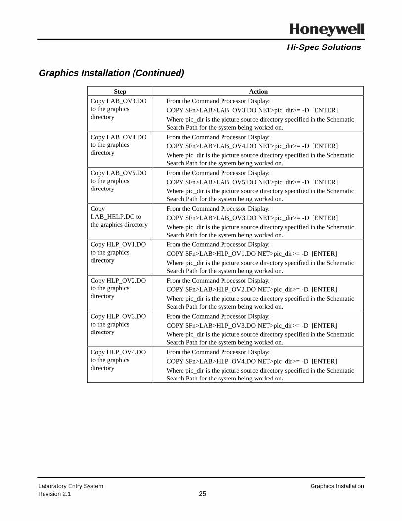
Hi-Spec Solutions
Laboratory Entry System Graphics InstallationRevision 2.1 25
Graphics Installation (Continued)
Step Action
Copy LAB_OV3.DOto the graphicsdirectory
From the Command Processor Display:
COPY $Fn>LAB>LAB_OV3.DO NET>pic_dir>= -D [ENTER]
Where pic_dir is the picture source directory specified in the SchematicSearch Path for the system being worked on.
Copy LAB_OV4.DOto the graphicsdirectory
From the Command Processor Display:
COPY $Fn>LAB>LAB_OV4.DO NET>pic_dir>= -D [ENTER]
Where pic_dir is the picture source directory specified in the SchematicSearch Path for the system being worked on.
Copy LAB_OV5.DOto the graphicsdirectory
From the Command Processor Display:
COPY $Fn>LAB>LAB_OV5.DO NET>pic_dir>= -D [ENTER]
Where pic_dir is the picture source directory specified in the SchematicSearch Path for the system being worked on.
CopyLAB_HELP.DO tothe graphics directory
From the Command Processor Display:
COPY $Fn>LAB>LAB_OV3.DO NET>pic_dir>= -D [ENTER]
Where pic_dir is the picture source directory specified in the SchematicSearch Path for the system being worked on.
Copy HLP_OV1.DOto the graphicsdirectory
From the Command Processor Display:
COPY $Fn>LAB>HLP_OV1.DO NET>pic_dir>= -D [ENTER]
Where pic_dir is the picture source directory specified in the SchematicSearch Path for the system being worked on.
Copy HLP_OV2.DOto the graphicsdirectory
From the Command Processor Display:
COPY $Fn>LAB>HLP_OV2.DO NET>pic_dir>= -D [ENTER]
Where pic_dir is the picture source directory specified in the SchematicSearch Path for the system being worked on.
Copy HLP_OV3.DOto the graphicsdirectory
From the Command Processor Display:
COPY $Fn>LAB>HLP_OV3.DO NET>pic_dir>= -D [ENTER]
Where pic_dir is the picture source directory specified in the SchematicSearch Path for the system being worked on.
Copy HLP_OV4.DOto the graphicsdirectory
From the Command Processor Display:
COPY $Fn>LAB>HLP_OV4.DO NET>pic_dir>= -D [ENTER]
Where pic_dir is the picture source directory specified in the SchematicSearch Path for the system being worked on.

Hi-Spec Solutions
Laboratory Entry System System ConfigurationRevision 2.1 26
System Configuration
Configuration of the Laboratory Entry System is accomplished through the configuration/operatingdisplays and through direct entry to the CDS ports on the Master Graphics Point.
Setup of the Laboratory Entry System requires the following steps:
• CDS Configuration of Master Graphics Point
• Graphic Configuration of remaining Laboratory System Functions
• Linking CL Program.
Notes:
Configuration errors may occur if points are deleted. To correct this problem, the AO files must beunlinked and then relinked to reestablish dynamic indirection.
Link errors can occur, when an improper point type is configured in a CDS parameter. This is caused bya missing parameter. A null point containing all required parameters can be used in the configuration forlinking purposes only. After the CL is linked, the desired point is then entered into the proper CDSlocation.

Hi-Spec Solutions
Laboratory Entry System Completing Configuration (Operating Displays)Revision 2.1 27
Master Graphics Point Configuration (Direct CDS Entry)
Configuration data must be entered directly onto the master graphics point, LABMASTR. The requiredinformation and associated parameter are listed below.
Parameter Description Comments
CALC_PT(1..n) Tagname of desired Process/Unitpoints.
See page 21
ENGPAR(1) The current selected process/unitpoint within the system
Default = 1, This parameter is selectedlater from the operating display
ENGPAR(2) Total number of Process/Unitpoints within the lab system.
This parameter sets the number ofprocess/unit points displayed.
The remaining configuration is completed using the laboratory system operating and configurationdisplays. Although it is possible to configure the system through direct CDS entry it is highlydiscouraged.

Hi-Spec Solutions
Laboratory Entry System Completing Configuration (Operating Displays)Revision 2.1 28
Lab Configuration through Displays
Once all of the required points have been built and the master graphics point configured, the remainingconfiguration is performed using the Laboratory Entry System displays. To begin, call up the operatingdisplay by selecting SCHEM, and entering LAB_SYS into the schematic port.
Graphic LAB_SYS
Continued

Hi-Spec Solutions
Laboratory Entry System Completing Configuration (Operating Displays)Revision 2.1 29
Lab Configuration through Displays (Continued)
Selecting a Process/Unit Point
To begin the configuration process, first select the desired process/unit area. The following procedureoutlines the selection task.
• Select SCHEM and enter LAB_SYS
• In the lower left corner select "SELECT UNIT" and a new menu bar appears.
• Select the desired Process/Unit area, the main menu bar now returns.
Configuring the Process/Unit Point
The next step is to configure the process/unit point with the desired bias calculation points, numericstorage points, keylevel access, and time stamp associations:
• Select the "CONFIG DISPLAY" button within the menu bar. A new overlay appears which providesaccess to the overall system configuration.
• Select an entry port within the "CALC PNT" column. Enter a point name which corresponds to either alab numeric (Gravity, Sulfur, Viscosity point) or a bias calculation point.
• Select the "CALC TYPE," either numeric or bias calculation.
• Provide a time stamp index as a sample association number. This index number is used to direct timestamp data collection. If CALC PNT (1) is a gravity point then the index for TIME (1) could be setequal to 1. If CALC PNT (2) were the 90% bias calculation for the same material as CALC PNT (1)then TIME (2) would also be equal to 1. Therefore, these 2 points share the same index value. Thisthen says that when a sample is drawn, the gravity and the 90% point calculation uses the same timestamp. A new index number must have the same number as the line 3 in the left and column.
• Select the desired display "KEYLEVEL." This can be used to customized the display to fit anyoperating environment.
• If within the "CALC TYPE" column, "BIAS" was selected, a new target will appear under the headingof "ADDITIONAL CFG." Selection of this target provides a new overlay for the configuration of thebiasing routine. See next page.
• Once all of the process/unit points and the associated parameters have been defined return to theoperating overlay by selecting the "PROP DISPLAY" target.

Hi-Spec Solutions
Laboratory Entry System Completing Configuration (Operating Displays)Revision 2.1 30
Lab Configuration through Displays (Continued)
Altering the Property Button Descriptions
After configuring the process/unit point, the property description buttons should be verified to ensure theyare correct. If the button name is truncated or needs to be altered to better reflect the property:
• Select the "SCHEM" button and enter "PEEKPOKE," a standard Honeywell display.
• Select any open cell and type "PNT_NAME.PTDESC," where PNT_NAME is the name of the systempoint.
• Select the old point description and enter a new description in the data port provided and press ENTER.
• Return to LAB_SYS and examine the property descriptions.
Configuring a Bias Calculation Point
Once the lab operating displays and process/unit areas have been configured, the actual bias calculationpoints must be configured. To complete the configuration execute the following tasks:
• Select the "CONFIG DISPLAY" button from the lower right corner of the LAB_SYS menu bar, thisbrings up the process/unit configuration overlay.
• Select the "ADD BIAS CONFIG" target. This provides a new configuration overlay.
• The new overlay provides the configuration display for the bias calculation points. The following tabledescribes each of the fields and action required and the CDS storage for that configuration field.

Hi-Spec Solutions
Laboratory Entry System Completing Configuration (Operating Displays)Revision 2.1 31
Bias Calculation Display Input Fields
Selection Port Parameter Action
Additive Bias Calc Pnt $_DDB The current bias point is displayed in this field.
Calculation PNT CALC_PT Enter the point LAB_NULL after linking the AOADDBIAS replace LAB_NULL with the desiredInferred Property Calculation point.
History Data Scope[HM] [HM&A]
ENGPAR(12) History Module only => 1.0History Module and Archives => 0.0
History SamplingFreq.
ENGPAR(13) Enter the desired sampling frequency in SECONDSValid Values are (5, 10, 20, or 60).
# of History Values ENGPAR(11) Enter the number of history values to be collected,the maximum value is 100.0.
# of History Valuesafter Sampling Time
ENGPAR(14) Enter the number of values to be collected AFTERthe sampling time. (Less than ENGPAR(11)).
Max Lab ValueConsidered
ENGPAR(6) Enter the maximum allowable laboratory valueconsidered for biasing.
Mim Lab ValueConsidered
ENGPAR(7) Enter the minimum allowable laboratory valueconsidered for biasing.
Bias CalculationDeadband
ENGPAR(8) Enter the number for a deadband where the lab andcalculated values are considered equal. This MUSTbe a non-zero value.
Max Change ENGPAR(9) Enter the maximum allowed change to the additivebias.
Process/SampleDeadtime
ENGPAR(10) Enter the number of minutes of deadtime betweenthe process and the sample point.
Gain on Additive Bias ENGPAR(15) Enter a gain or percentage of the new bias which isapplied to the existing bias.
After completing the Bias Calculation Point configuration a CL block must be link to the point. Toaccomplish this follow the steps outlined below.
Step Action
Link ADDBIAS From the Command Processor Display:
LK $Fn>AO>ADDBIAS point_name [ENTER]
Link PARMHIST
ReplaceLAB_NULL
Return to the configuration display and replace LAB_NULL with the desiredinferential calculation point name.
Activate point Call up the point detail and activate the point.

Hi-Spec Solutions
Laboratory Entry System Completing Configuration (Operating Displays)Revision 2.1 32
Configuring Special Note
For each bias calculation point there are (2) parameters which MUST be historized on the system. Referto the Honeywell documentation for a description of the historization procedure. The following:
• CALC_PT.CALC_VAL(1) - Which is the value of the inferential property calculation.
• CALC_PT.LAB_BIAS(2) - Which is the value of the additive bias used within the inferential propertycalculation point.
Where CALC_PT is the actual property calculation point, NOT the name of the bias calculation point.
For PARMHIST block, all Point.param in SNAME must be historized. Data written to
PATHNAME = NET>XXXX> where directory XXXX is 4 non-blank characters.
HISFILE = ZZZDATA.XX Must be an 8 digit non-blank filename.
When the file is first created, column header information is written out. The proplerty calc and Lab biasvalue are written out to the history file in the last two columns.
EXECSTAT (1) = Number of points (SNAME entries)
(2) = Non-zero to execute file write.

Hi-Spec Solutions
Laboratory Entry System Linking CL ProgramRevision 2.1 33
Link CL Programs
Step Action
Link LAB_TIME From the Command Processor Display:
LK $Fn>AO>LAB_TIME process/unit point [ENTER]
Activate point Call up the point detail and activate the point.
Verify Operation Verify that LAB_TIME is running without any CL errors.

Hi-Spec Solutions
Laboratory Entry System Linking CL ProgramRevision 2.1 34

Hi-Spec Solutions
Honeywell Hi-Spec Solutions • 16404 N. Black Canyon Hwy. • Phoenix, AZ 85023
Advanced Control Package
Pour Point Calculation
CONTROLLED
May 1995Revision 3.0

Hi-Spec Solutions
Pour Point Calculation Revision HistoryRevision 3.0
16404 North Black Canyon Hiway • Phoenix, Az 85023325 Rolling Oaks Dr • Thousand Oaks, CA 91361-1200
10333 Richmond, Suite 1110 • Houston, Tx 77042Chilworth Research Centre • Southampton, United Kingdom SO1 7NP

Hi-Spec Solutions
Pour Point Calculation ContentsRevision 3.0
Table of ContentsOverview.........................................................................................................................................1
Acronym List ..................................................................................................................................3
Hardware and Software Requirements ...........................................................................................4
Instrumentation (Process Inputs).....................................................................................................5
Process Diagram .............................................................................................................................6
Detailed Description .......................................................................................................................7
Point Structure ..................................................................................................................8
Process Inputs ...................................................................................................................9
Continued..........................................................................................................................9
Process Inputs (Continued) .............................................................................................10
Configuration Inputs .......................................................................................................11
Configuration Inputs (Continued)...................................................................................12
Configuration Inputs (Continued)...................................................................................13
Continued........................................................................................................................13
Configuration Inputs (Continued)...................................................................................14
Calculation Outputs ........................................................................................................15
Calculation Outputs (Continued) ....................................................................................16
Error Codes ...................................................................................................................................17
Diagnostic Error Codes...................................................................................................18
Diagnostic Error Codes (Continued)...............................................................................19
Molecular Weight Error Codes .......................................................................................20
EFV Temperature Error Codes .......................................................................................21
Configuration and Tuning.............................................................................................................22
Biases in the Pour Point Program ...................................................................................23
Tuning Parameters ..........................................................................................................24
Algorithms ....................................................................................................................................25
Algorithms (Continued) ..................................................................................................26
Installation Procedure ...................................................................................................................27
Preparation for Installation..............................................................................................28
CDS and PL Installation .................................................................................................29
Building Pour Point Calculation Point............................................................................30
Configuration Graphics Installation................................................................................31

Hi-Spec Solutions
Pour Point Calculation ContentsRevision 3.0
Configure Calculation Point .........................................................................................................32
Point Configuration Using Graphic POUR_CFG...........................................................33
Point Configuration Using Graphic POUR_CFG (Continued).......................................34
Point Configuration Using Graphic POUR_CFG (Continued).......................................35
Point Configuration Using Graphic POUR_CFG (Continued).......................................36
Point Configuration through Direct CDS Entry..............................................................37
Point Configuration through Direct CDS Entry (Continued) .........................................38
Point Configuration through Direct CDS Entry (Continued) .........................................39
Point Configuration through Direct CDS Entry (Continued) .........................................40
Point Configuration through Direct CDS Entry (Continued) .........................................41
Point Configuration through Direct CDS Entry (Continued) .........................................42
Point Configuration through Direct CDS Entry (Continued) .........................................43
Link CL Programs...........................................................................................................44

Hi-Spec Solutions
Pour Point Calculation Overview
Revision 3.0 1
Overview
Definition. The pour point temperature provides an estimate of the relative amount ofwax within the petroleum fraction. A pour point test will not indicate the actual amountof wax content within a fraction, but does indicate that most of the wax above the pourtemperature has been removed. The pour point temperature is affected by thehydrocarbons paraffinic content, symmetrical molecular structures, and aromaticcontent.
Application. The pour point of a hydrocarbon fraction is an important specification fordistillates and diesel fuels.
Calculation. The pour point calculation program calculates the inferential pour pointof a hydrocarbon product based on:
• Processinputs:
Temperatures, pressures, and flows
• Characterizationinputs:
Watson K and specific gravity
• Calculatedvalues:
Molecular weight, equilibrium flash vaporizationtemperature, and the TBP 50% point.
Incentive. 1. To indicate how closely a hydrocarbon stream is meeting the pour pointspecification.
2. To eliminate dead time associated with laboratory analysis and on-lineanalyzers.
3. To provide a real-time input for use in advanced control applications.

Hi-Spec Solutions
Pour Point Calculation Overview
Revision 3.0 2
30252015105 0 10
15
20
25
30
Calc Pour Lab Pour
Unbiased Pour Point Predictions
Samples
Figure 1
The lab results in Figure 1 are shown with error bars of + or - 1 degree F. The ASTM D97-85 Pour Point, states a reproducibility of + or -5.0 degrees F when the test isperformed by the same technician.

Hi-Spec Solutions
Pour Point Calculation Acronym List
Revision 3.0 3
Acronym List
Term AcronymApplication Module AM
Local Control Network LCN
Universal Station US
control language CL
process variable PV
custom data segment CDS
Equilibrium Flash Vaporization EFV
pounds per square inch psi
Parameter List PL
CL object code file extension AO
true boiling point TBP

Hi-Spec Solutions
Pour Point Calculation Hardware and Software Requirements
Revision 3.0 4
Hardware and Software Requirements
Requirement DescriptionHardware Platform TDC 3000 AM
Special Boards None
Other Computing Systems None
LCN Release Release 300 or later
AM Load Modules None
US Load Modules None
Other Packages None
Other Control Applications None
Software Inputs Specific gravities and Watson K factors for tower products and theinternal liquid, must exist as points on the LCN

Hi-Spec Solutions
Pour Point Calculation Instrumentation (Process Inputs)
Revision 3.0 5
Instrumentation (Process Inputs)
Process Input1 Required Recommended
Input stream flow rates XDraw temperature XDraw pressure X
1 Required inputs can sometimes be obtained by inference. However, calculations based upon inferred data can be less accurate than calculations based upon direct readings.

Hi-Spec Solutions
Pour Point Calculation Process Diagram
Revision 3.0 6
Process Diagram
To be determined.

Hi-Spec Solutions
Pour Point Calculation Detailed Description
Revision 3.0 7
Detailed Description
The tables in this section describe the following Pour Point program architecture:
• Point Structure
• Process Inputs
• Configuration Inputs
• Calculation Outputs.

Hi-Spec Solutions
Pour Point Calculation Point Structure
Revision 3.0 8
Point Structure
Point StructurePoint Type AM Regulatory, CL
PV_Type CL
CTL_Type Any
Custom Data Segment POUR_CDS.CL
Algorithm POUR_PNT.CL
Insertion Point PV_ALG
Slot 5
Output The calculated inferential Pour point is displayed as the point’s PV

Hi-Spec Solutions
Pour Point Calculation Process Inputs
Revision 3.0 9
Process Inputs
Process Inputs
Critical2
Parameter Description Units Yes NoPRESS_PT Tagname of source for draw pressure Any pressure units XTEMP_PT Tagname of source for draw temperature °F or °C XFLOW_PT(1) Tagname for stream 1 flow rate Any flow units XFLOW_PT(2) Tagname for stream 2 flow rate Any flow units XFLOW_PT(3) Tagname for stream 3 flow rate Any flow units XFLOW_PT(4) Tagname for stream 4 flow rate Any flow units XFLOW_PT(5) Tagname for stream 5 flow rate Any flow units XFLOW_PT(6) Tagname for stream 6 flow rate Any flow units XFLOW_PT(7) Tagname for stream 7 flow rate Any flow units XFLOW_PT(8) Tagname for stream 8 flow rate Any flow units XFLOW_PT(9) Tagname for stream 9 flow rate Any flow units XFLOW_PT(10) Tagname for stream 10 flow rate Any flow units XGRAV_PT(1) Tagname for stream 1 gravity input °API or none (S.G.)XGRAV_PT(2) Tagname for stream 2 gravity input °API or none (S.G.)XGRAV_PT(3) Tagname for stream 3 gravity input °API or none (S.G.)XGRAV_PT(4) Tagname for stream 4 gravity input °API or none (S.G.)XGRAV_PT(5) Tagname for stream 5 gravity input °API or none (S.G.)XGRAV_PT(6) Tagname for stream 6 gravity input °API or none (S.G.)XGRAV_PT(7) Tagname for stream 7 gravity input °API or none (S.G.)XGRAV_PT(8) Tagname for stream 8 gravity input °API or none (S.G.)XGRAV_PT(9) Tagname for stream 9 gravity input °API or none (S.G.)XGRAV_PT(10) Tagname for stream 10 gravity input °API or none (S.G.)XWATK_PT(1) Tagname for stream 1 Watson K factor None XWATK_PT(2) Tagname for stream 1 Watson K factor None XWATK_PT(3) Tagname for stream 1 Watson K factor None X
Continued
2 Critical indicates that a bad input causes the output of the calculation to be set BAD.

Hi-Spec Solutions
Pour Point Calculation Process Inputs
Revision 3.0 10
Process Inputs (Continued)
Process Inputs
Critical3
Parameter Description Units Yes NoWATK_PT(4) Tagname for stream 1 Watson K factor None XWATK_PT(5) Tagname for stream 1 Watson K factor None XWATK_PT(6) Tagname for stream 1 Watson K factor None XWATK_PT(7) Tagname for stream 1 Watson K factor None XWATK_PT(8) Tagname for stream 1 Watson K factor None XWATK_PT(9) Tagname for stream 1 Watson K factor None XWATK_PT(10) Tagname for stream 1 Watson K factor None X
.
3 Critical indicates that a bad input causes the output of the calculation to be set BAD.

Hi-Spec Solutions
Pour Point Calculation Configuration Inputs
Revision 3.0 11
Configuration Inputs
Configuration InputsParameter Description Units
T_BIAS Additive bias to draw temperature Same units asTEMP_PT
P_BIAS Additive bias to draw pressure Same units asPRESS_PT
ENGPAR(1) Number of configured streams (2.0 < ENGPAR(1) <= 10.0)
N/A
ENGPAR(2) Local atmospheric pressure (a value of 14.696 will be usedinternally if a zero is entered)
Same units asPRESS_PT
ENGPAR(3) Location of product stream within configured streams None
ENGPAR(4) Indicates if the mole weight for stream 1 is entered orcalculated. (0 = Calc, 1 = Entered)
None
ENGPAR(5) Indicates if the mole weight for stream 2 is entered orcalculated. (0 = Calc, 1 = Entered)
None
ENGPAR(6) Indicates if the mole weight for stream 3 is entered orcalculated. (0 = Calc, 1 = Entered)
None
ENGPAR(7) Indicates if the mole weight for stream 4 is entered orcalculated. (0 = Calc, 1 = Entered)
None
ENGPAR(8) Indicates if the mole weight for stream 5 is entered orcalculated. (0 = Calc, 1 = Entered)
None
ENGPAR(9) Indicates if the mole weight for stream 6 is entered orcalculated. (0 = Calc, 1 = Entered)
None
ENGPAR(10) Indicates if the mole weight for stream 7 is entered orcalculated. (0 = Calc, 1 = Entered)
None
ENGPAR(11) Indicates if the mole weight for stream 8 is entered orcalculated. (0 = Calc, 1 = Entered)
None
ENGPAR(12) Indicates if the mole weight for stream 9 is entered orcalculated. (0 = Calc, 1 = Entered)
None
ENGPAR(13) Indicates if the mole weight for stream 10 is entered orcalculated. (0 = Calc, 1 = Entered)
None
ENGPAR(14) Spare - Available for future development N/A
ENGPAR(15) Flag to force calculation BAD( 0 => Do not set BAD; 1 => Set calculation BAD)
N/A
LAB_BIAS(1) Multiplicative bias applied to the mole fraction N/A
LAB_BIAS(2) Additive laboratory bias to calculated pour point Same units asTEMP_PT(1)
B1 Scaler value used to adjust the Coef (A) within the EFV toD86 convertion rountine.
N/A
B2 Scaler value used to adjust the Coef (B) within the EFV toD86 convertion rountine.
N/A
Continued

Hi-Spec Solutions
Pour Point Calculation Configuration Inputs
Revision 3.0 12
Configuration Inputs (Continued)
Configuration InputsParameter Description Units
B3 Scaler value used to adjust the Coef (C) within the EFV toD86 convertion rountine.
N/A
NUMER(1) Numerator indication for stream 1(0 = Not in Numer, 1 = In Numer)
None
NUMER(2) Numerator indication for stream 2(0 = Not in Numer, 1 = In Numer)
None
NUMER(3) Numerator indication for stream 3(0 = Not in Numer, 1 = In Numer)
None
NUMER(4) Numerator indication for stream 4(0 = Not in Numer, 1 = In Numer)
None
NUMER(5) Numerator indication for stream 5(0 = Not in Numer, 1 = In Numer)
None
NUMER(6) Numerator indication for stream 6(0 = Not in Numer, 1 = In Numer)
None
NUMER(7) Numerator indication for stream 7(0 = Not in Numer, 1 = In Numer)
None
NUMER(8) Numerator indication for stream 8(0 = Not in Numer, 1 = In Numer)
None
NUMER(9) Numerator indication for stream 9(0 = Not in Numer, 1 = In Numer)
None
NUMER(10) Numerator indication for stream 10(0 = Not in Numer, 1 = In Numer)
None
CONV_FAC(1) Conversion factor for stream 1 - (Input units => mass) From input unitsto Mass
CONV_FAC(2) Conversion factor for stream 2 - (Input units => mass) From input unitsto Mass
CONV_FAC(3) Conversion factor for stream 3 - (Input units => mass) From input unitsto Mass
CONV_FAC(4) Conversion factor for stream 4 - (Input units => mass) From input unitsto Mass
CONV_FAC(5) Conversion factor for stream 5 - (Input units => mass) From input unitsto Mass
CONV_FAC(6) Conversion factor for stream 6 - (Input units => mass) From input unitsto Mass
CONV_FAC(7) Conversion factor for stream 7 - (Input units => mass) From input unitsto Mass
CONV_FAC(8) Conversion factor for stream 8 - (Input units => mass) From input unitsto Mass
Continued

Hi-Spec Solutions
Pour Point Calculation Configuration Inputs
Revision 3.0 13
Configuration Inputs (Continued)
Configuration InputsParameter Description Units
CONV_FAC(9) Conversion factor for stream 9 - (Input units => mass) From input unitsto Mass
CONV_FAC(10) Conversion factor for stream 10 - (Input units => mass) From input unitsto Mass
CONV_FAC(11) Stripper pressure (PRESS_PT) multiplicative conversionfactor
From input unitsto psi
CONV_FAC(12) Input temperature unit flag; ( 0 => °F, 1 => °C )
N/A
CONV_FAC(13) Input gravity type flag: ( 0 => API, 1 => Specific gravity )
N/A
CONV_FAC(14) Spare - Available for future development N/A
CONV_FAC(15) Spare - Available for future development N/A
FILTER(1) Filter time for FLOW_PT(1) Minutes
FILTER(2) Filter time for FLOW_PT(2) Minutes
FILTER(3) Filter time for FLOW_PT(3) Minutes
FILTER(4) Filter time for FLOW_PT(4) Minutes
FILTER(5) Filter time for FLOW_PT(5) Minutes
FILTER(6) Filter time for FLOW_PT(6) Minutes
FILTER(7) Filter time for FLOW_PT(7) Minutes
FILTER(8) Filter time for FLOW_PT(8) Minutes
FILTER(9) Filter time for FLOW_PT(9) Minutes
FILTER(10) Filter time for FLOW_PT(10) Minutes
FILTER(11) Filter time for input gravities - GRAV_PT Minutes
FILTER(12) Filter time for input Watson K factors - WATK_PT Minutes
FILTER(13) Filter time for the input temperature - TEMP_PT Minutes
FILTER(14) Filter time for the input pressure - PRESS_PT Minutes
FILTER(15) Filter time for multiplicative bias - LAB_BIAS(1) Minutes
FILTER(16) Filter time for additive laboratory bias - LAB_BIAS(2) Minutes
FILTER(17) Filter time for the calculated mole fraction Minutes
FILTER(18) Spare - Available for future development Minutes
FILTER(19) Spare - Available for future development Minutes
FILTER(20) Spare - Available for future development Minutes
MOLWT(1) Molecular weight for stream 1 - ( Calc or Entered ) lb / (lb-mol)
MOLWT(2) Molecular weight for stream 2 - ( Calc or Entered ) lb / (lb-mol)
MOLWT(3) Molecular weight for stream 3 - ( Calc or Entered ) lb / (lb-mol)
MOLWT(4) Molecular weight for stream 4 - ( Calc or Entered ) lb / (lb-mol)
Continued

Hi-Spec Solutions
Pour Point Calculation Configuration Inputs
Revision 3.0 14
Configuration Inputs (Continued)
Configuration InputsParameter Description Units
MOLWT(5) Molecular weight for stream 5 - ( Calc or Entered ) lb / (lb-mol)
MOLWT(6) Molecular weight for stream 6 - ( Calc or Entered ) lb / (lb-mol)
MOLWT(7) Molecular weight for stream 7 - ( Calc or Entered ) lb / (lb-mol)
MOLWT(8) Molecular weight for stream 8 - ( Calc or Entered ) lb / (lb-mol)
MOLWT(9) Molecular weight for stream 9 - ( Calc or Entered ) lb / (lb-mol)
MOLWT(10) Molecular weight for stream 10 - ( Calc or Entered ) lb / (lb-mol)

Hi-Spec Solutions
Pour Point Calculation Calculation Outputs
Revision 3.0 15
Calculation Outputs
Calculation OutputsParameter Description Units
PVCALC Calculated hydrocarbon product inferential pour point Temperatureinput units
CALC_VAL(1) Calculated hydrocarbon product inferential pour point Temperatureinput units
CALC_VAL(2) Calculated moles in the numerator Moles
CALC_VAL(3) Calculated moles in the denominator Moles
CALC_VAL(4) Calculated mole fraction None
CALC_VAL(5) Calculated effective pressure psi
CALC_VAL(6) Calculated EFV temperature Temperatureinput units
CALC_VAL(7) ASTM D86 50% point temperature Temperatureinput units
CALC_VAL(8) Calculated TBP 50% point temperature Temperatureinput units
CALC_VAL(9) Calculated low pour search limit N/A
CALC_VAL(10) Calculated high pour search limit N/A
CALC_VAL(11) Calculated pour point limit ratio N/A
CALC_VAL(12) Calculated pour point delta value N/A
CALC_VAL(13) Calculated moles input from stream 1 Moles
CALC_VAL(14) Calculated moles input from stream 2 Moles
CALC_VAL(15) Calculated moles input from stream 3 Moles
CALC_VAL(16) Calculated moles input from stream 4 Moles
CALC_VAL(17) Calculated moles input from stream 5 Moles
CALC_VAL(18) Calculated moles input from stream 6 Moles
CALC_VAL(19) Calculated moles input from stream 7 Moles
CALC_VAL(20) Calculated moles input from stream 8 Moles
CALC_VAL(21) Calculated moles input from stream 9 Moles
CALC_VAL(22) Calculated moles input from stream 10 Moles
CALC_VAL(23) Spare - Available for future development N/A
CALC_VAL(24) Spare - Available for future development N/A
CALC_VAL(25) Spare - Available for future development N/A
STATUS(1) Diagnostic indication of location and possible causes ofprogram error
N/A
STATUS(2) Diagnostic indication of subroutine error N/A
REV_NO Program revision number N/A
Continued

Hi-Spec Solutions
Pour Point Calculation Calculation Outputs
Revision 3.0 16
Calculation Outputs (Continued)
Calculation OutputsParameter Description Units
FILT_VAL(1) Filtered value of input stream 1 flow rate Input units
FILT_VAL(2) Filtered value of input stream 2 flow rate Input units
FILT_VAL(3) Filtered value of input stream 3 flow rate Input units
FILT_VAL(4) Filtered value of input stream 4 flow rate Input units
FILT_VAL(5) Filtered value of input stream 5 flow rate Input units
FILT_VAL(6) Filtered value of input stream 6 flow rate Input units
FILT_VAL(7) Filtered value of input stream 7 flow rate Input units
FILT_VAL(8) Filtered value of input stream 8 flow rate Input units
FILT_VAL(9) Filtered value of input stream 9 flow rate Input units
FILT_VAL(10) Filtered value of input stream 10 flow rate Input units
FILT_VAL(11) Stream 1 filtered gravity input, GRAV_PT(1) Input units
FILT_VAL(12) Stream 2 filtered gravity input, GRAV_PT(2) Input units
FILT_VAL(13) Stream 3 filtered gravity input, GRAV_PT(3) Input units
FILT_VAL(14) Stream 4 filtered gravity input, GRAV_PT(4) Input units
FILT_VAL(15) Stream 5 filtered gravity input, GRAV_PT(5) Input units
FILT_VAL(16) Stream 6 filtered gravity input, GRAV_PT(6) Input units
FILT_VAL(17) Stream 7 filtered gravity input, GRAV_PT(7) Input units
FILT_VAL(18) Stream 8 filtered gravity input, GRAV_PT(8) Input units
FILT_VAL(19) Stream 9 filtered gravity input, GRAV_PT(9) Input units
FILT_VAL(20) Stream 10 filtered gravity input, GRAV_PT(10) Input units
FILT_VAL(21) Stream 1 filtered Watson K input, WATK_PT(1) Input units
FILT_VAL(22) Stream 2 filtered Watson K input, WATK_PT(2) Input units
FILT_VAL(23) Stream 3 filtered Watson K input, WATK_PT(3) Input units
FILT_VAL(24) Stream 4 filtered Watson K input, WATK_PT(4) Input units
FILT_VAL(25) Stream 5 filtered Watson K input, WATK_PT(5) Input units
FILT_VAL(26) Stream 6 filtered Watson K input, WATK_PT(6) Input units
FILT_VAL(27) Stream 7 filtered Watson K input, WATK_PT(7) Input units
FILT_VAL(28) Stream 8 filtered Watson K input, WATK_PT(8) Input units
FILT_VAL(29) Stream 9 filtered Watson K input, WATK_PT(9) Input units
FILT_VAL(30) Stream 10 filtered Watson K input, WATK_PT(10) Input units
FILT_VAL(31) Filtered value of input temperature, TEMP_PT Input units
FILT_VAL(32) Filtered value of input pressure, PRESS_PT Input units
FILT_VAL(33) Filtered value of input multiplicative bias, LAB_BAIS(1) N/A
FILT_VAL(34) Filtered value of input additive bias, LAB_BAIS(2) N/A
FILT_VAL(35) Filtered value of calculated mole fraction None

Hi-Spec Solutions
Pour Point Calculation Error Codes
Revision 3.0 17
Error Codes
The tables in this section describe the following program error codes:
• Diagnostic error codes
• Molecular weight error codes
• EFV temperature error codes.

Hi-Spec Solutions
Pour Point Calculation Diagnostic Error Codes
Revision 3.0 18
Diagnostic Error Codes
Diagnostic Error CodesParameter Value Description
STATUS(1) 0.0 No errors
1.0 Set calculation BAD flag on [ENGPAR(15)<>0]
2.0 Input number of streams is outside the range 1 to 10 [2 <= ENGPAR(1) <= 10]
3.0 Location of the product stream within the configured streaminformation is out of range. [2 <= ENGPAR(2) <= 10]
4.0 FLOW_PT(1) has a null point entered or has a bad PV
5.0 FLOW_PT(2) has a null point entered or has a bad PV
6.0 FLOW_PT(3) has a null point entered or has a bad PV
7.0 FLOW_PT(4) has a null point entered or has a bad PV
8.0 FLOW_PT(5) has a null point entered or has a bad PV
9.0 FLOW_PT(6) has a null point entered or has a bad PV
10.0 FLOW_PT(7) has a null point entered or has a bad PV
11.0 FLOW_PT(8) has a null point entered or has a bad PV
12.0 FLOW_PT(9) has a null point entered or has a bad PV
13.0 FLOW_PT(10) has a null point entered or has a bad PV
14.0 GRAV_PT(1) has a null point entered or has a bad PV
15.0 GRAV_PT(2) has a null point entered or has a bad PV
16.0 GRAV_PT(3) has a null point entered or has a bad PV
17.0 GRAV_PT(4) has a null point entered or has a bad PV
18.0 GRAV_PT(5) has a null point entered or has a bad PV
19.0 GRAV_PT(6) has a null point entered or has a bad PV
20.0 GRAV_PT(7) has a null point entered or has a bad PV
21.0 GRAV_PT(8) has a null point entered or has a bad PV
22.0 GRAV_PT(9) has a null point entered or has a bad PV
23.0 GRAV_PT(10) has a null point entered or has a bad PV
24.0 WATK_PT(1) has a null point entered or has a bad PV
25.0 WATK_PT(2) has a null point entered or has a bad PV
26.0 WATK_PT(3) has a null point entered or has a bad PV
27.0 WATK_PT(4) has a null point entered or has a bad PV
28.0 WATK_PT(5) has a null point entered or has a bad PV
29.0 WATK_PT(6) has a null point entered or has a bad PV
30.0 WATK_PT(7) has a null point entered or has a bad PV
31.0 WATK_PT(8) has a null point entered or has a bad PV
32.0 WATK_PT(9) has a null point entered or has a bad PV
Continued

Hi-Spec Solutions
Pour Point Calculation Diagnostic Error Codes
Revision 3.0 19
Diagnostic Error Codes (Continued)
Diagnostic Error CodesParameter Value Description
STATUS(1) 33.0 WATK_PT(10) has a null point entered or has a bad PV
34.0 Error in user defined MOLWT(1) - ( Badvalue or value <= 0.0 )
35.0 Error in user defined MOLWT(2) - ( Badvalue or value <= 0.0 )
36.0 Error in user defined MOLWT(3) - ( Badvalue or value <= 0.0 )
37.0 Error in user defined MOLWT(4) - ( Badvalue or value <= 0.0 )
38.0 Error in user defined MOLWT(5) - ( Badvalue or value <= 0.0 )
39.0 Error in user defined MOLWT(6) - ( Badvalue or value <= 0.0 )
40.0 Error in user defined MOLWT(7) - ( Badvalue or value <= 0.0 )
41.0 Error in user defined MOLWT(8) - ( Badvalue or value <= 0.0 )
42.0 Error in user defined MOLWT(9) - ( Badvalue or value <= 0.0 )
43.0 Error in user defined MOLWT(10) - ( Badvalue or value <= 0.0 )
44.0 Error in calculating MOLWT(1) - see STATUS(2)
45.0 Error in calculating MOLWT(2) - see STATUS(2)
46.0 Error in calculating MOLWT(3) - see STATUS(2)
47.0 Error in calculating MOLWT(4) - see STATUS(2)
48.0 Error in calculating MOLWT(5) - see STATUS(2)
49.0 Error in calculating MOLWT(6) - see STATUS(2)
50.0 Error in calculating MOLWT(7) - see STATUS(2)
51.0 Error in calculating MOLWT(8) - see STATUS(2)
52.0 Error in calculating MOLWT(9) - see STATUS(2)
53.0 Error in calculating MOLWT(10) - see STATUS(2)
54.0 TEMP_PT has a null point entered, bad PV, or filter error
55.0 PRESS_PT has a null point entered, bad PV, or filter error
56.0 LAB_BIAS(1) has a bad value or filter error
57.0 LAB_BIAS(2) has a bad value or filter error
58.0 Calculated mole fraction has a bad value or filter error
59.0 Calculated partial pressure has a bad value or filter error
60.0 Calculated EFV temperature has a bad value
61.0 Pour point calculation return an error

Hi-Spec Solutions
Pour Point Calculation Molecular Weight Error Codes
Revision 3.0 20
Molecular Weight Error Codes
Molecular Weight Error CodesParameter Value Description
STATUS(2)4 0.0 No errors
1.0 Calculated molecular weight has a bad value
2.0 Input specific gravity has a bad value
3.0 Input Watson K has a bad value
-1.0 Input specific gravity or Watson K equal to or less than 0.0
4 STATUS(2) indicates errors returned by the molecular weight calculation subroutine.

Hi-Spec Solutions
Pour Point Calculation EFV Temperature Error Codes
Revision 3.0 21
EFV Temperature Error Codes
EFV Temperature Error CodesParameter Value Description
STATUS(2)5 0.0 No errors
1.0 Calculated EFV temperature has a bad value
2.0 Input temperature has a bad value
3.0 Input effective vapor pressure has a bad value
4.0 Input Watson K has a bad value
-1.0 Input temperature, effective vapor pressure, or Watson K has azero or negative value
5 STATUS(2) indicates errors returned by the EFV temperature calculation subroutine.

Hi-Spec Solutions
Pour Point Calculation Configuration and Tuning
Revision 3.0 22
Configuration and Tuning
This section describes the parameters and values used to configure and tune the packageto a specific application.
Biases
• Temperature Bias
• Pressure Bias
• Laboratory Additive Bias.
Tuning
• Multiplicative Bias
• Scaler Biases.

Hi-Spec Solutions
Pour Point Calculation Biases in the Pour Point Program
Revision 3.0 23
Biases in the Pour Point Program
The Pour Point program is equipped with the following additive biases:
• Input draw temperature
• Input draw pressure
• Laboratory bias for the pour point.
Bias ParametersParameter Description
T_BIAS Additive bias to input draw temperature TEMP_PT
P_BIAS Additive bias to input draw pressure PRESS_PT
LAB_BIAS(2) Additive laboratory bias to calculated pour point
Pressure and Temperature Bias. The pressure bias (P_BIAS) and temperature bias(T_BIAS) are added to the input values before performance of the unit conversions andshould be entered in the same units as the input pressure and temperatures.
The T_BIAS parameter is used when there is a known error in either the draw orproduct temperature indication. The P_BIAS parameter is used when the actual drawpressure is not available as an input to the calculation.
Example. If the column overhead pressure is used for PRESS_PT, then P_BIAS is setequal to the pressure change between the column overhead and the draw location.
Additive Laboratory Bias. The pour point program biases the calculated pour pointtemperature using the parameters LAB_BIAS(2) for additive biasing. Only the additivebias, LAB_BIAS(2), is used dynamically and is expected to be updated manually orwith a laboratory results interface package.
Both PVCALC and CALC_VAL(1) contain the biased calculated pour pointtemperatures. The unbiased pour is not reported. For unbiased calculated results setLAB_BIAS(2) = 0.0

Hi-Spec Solutions
Pour Point Calculation Tuning Parameters
Revision 3.0 24
Tuning Parameters
If there is a sustained offset between the calculated and laboratory pour points even withthe use of the biasing, the following parameters can be adjusted.
Parameter Suggested AdjustmentT_BIAS Increasing the temperature additive bias increase the calculated pour
point value.
LAB_BIAS(1) Increasing the multiplicative bias decreases the calculated pour pointvalue. (This bias is applied to the calculated mole fraction)
B1 Scaler value used to adjust the Coef (A) within the EFV to D86convertion rountine.
B2 Scaler value used to adjust the Coef (B) within the EFV to D86convertion rountine.
B3 Scaler value used to adjust the Coef (C) within the EFV to D86convertion rountine.
Temperature Bias [T_BIAS]
If the vapor temperature at the draw tray is not directly measured, then the inputtemperature may be biased to give the approximate vapor temperature. The vaportemperature is corrected for pressure to determine the EFV temperature. The EFVtemperature is then converted to the TBP temperature.
Multiplicative Bias [LAB_BAIS(1)]
The mole fraction of hydrocarbon vapor which is in equilibrium with the hydrocarbonproduct is calculated using the internal reflux, all product coming off the column abovethe draw tray and above (to the column overhead), and inert material. Themultiplicative bias is applied to the mole fraction. The mole fraction is used todetermine the partial pressure of the hydrocarbon vapor which is used to determine theEFV temperature. The EFV temperature is then converted to the desired TBPtemperature.
Scaler Biases [B1, B2, and B3]
The routine which converts from the calculated EFV temperature to the TBP 50% pointtemperature has three parameters. These three parameters can be indivigually scaled ortuned to provide a clear representation of the TBP value. The default values are all 1.0and should remain at this value unless calculation performance requires a change.
Note: The EFV to TBP equation is highly sensitive to changes in these parameters.Once altered from their default values re-tuning of the entire calculation is required.

Hi-Spec Solutions
Pour Point Calculation Algorithms
Revision 3.0 25
Algorithms
Conversion of Engineering Units. The input process flows can have any units, but theconversion factors must be configured to yield consistent MASS flow units, as shown inEquation 1:
flow(i) = FLOW_PT(i).PV * CONV_FAC(i)
Where:
flow(i) = Process flow i converted to MASS for internal useFLOW_PT(i).PV = Input process flow i in any unitsCONV_FAC(i) = Conversion for flow i from input units to MASS units
Equation 1
The input process pressure can have any units. However, the conversion factor must beconfigured to yield psi, as shown in Equation 2:
press = ( (PRESS_PT.PV +P_BIAS) *CONV_FAC(11) ) + atm_pres
Where:
press = Process pressure converted to psia for internal usePRESS_PT.PV = Input process pressure in any gauge unitsP_BIAS = Bias to input pressure in input gauge unitsCONV_FAC(11) = Conversion factor for pressure from input units to psiatm_pres = Atmospheric pressure in psi
and When:ENG_PAR(2) <= 0 then (atm_pres = 14.696 )
else ( atm_pres = ENG_PAR(2) * CONV_FAC(11) )
Equation 2
Continued

Hi-Spec Solutions
Pour Point Calculation Algorithms
Revision 3.0 26
Algorithms (Continued)
Pour Point Calculation. The pour point is calculated from process inputs using theHoneywell pour point calculation, as shown in Equation 3:
pour_pnt = Function[draw_t, press, prod_char]
Where:
pour_pnt = Calculated pour pointdraw_t = Draw temperaturepress = Draw pressureprod_char = Material characterization (gravity and Watson K)
Equation 3
Biasing. One bias factor is provided to reduce the offset between the inferential pourpoint and a laboratory or on-line analysis-determined pour point. The additive bias isused, as shown in Equation 4:
bias_pour = pour_pnt + LAB_BIAS(2)
Where:
bias_pour = Biased pour pointpour_pnt = Calculated pour pointLAB_BIAS(2) = Additive laboratory bias
Equation 4

Hi-Spec Solutions
Pour Point Calculation Installation Procedure
Revision 3.0 27
Installation Procedure
This document describes the installation procedure for POUR_PNT on the TDC 3000System AM.
This section covers the following topics:
• Preparation for Installation
• CDS and PL Installation
• Building Pour Point Calculation Point
• Configuration Graphics Installation.

Hi-Spec Solutions
Pour Point Calculation Preparation for Installation
Revision 3.0 28
Preparation for Installation
Step ActionGather media Gather the following items:
• Removable media containing the directory POUR• Commissioning Worksheet
Make media backup Make a backup copy of media/directory on a US with drives n and mconfigured as follows:
Media:FCOPY $Fn $FmDirectory only:CD $Fm>vol_dir> POURCOPY $Fn>POUR>*.* $Fm>POUR>= -V -DWhere $Fn is the drive with the source media and $Fm is the drive withthe target media

Hi-Spec Solutions
Pour Point Calculation CDS and PL Installation
Revision 3.0 29
CDS and PL Installation
This procedure must be done once per LCN installation.
Step ActionSet volumepathnames
From Modify Volume Paths display:CL CUSTOM GDF: NET>CDSG>
USER DEFLT PATH: $Fn>POUR
CompilePOUR_CDS.CL
From the Command Processor display, compile the CDS file, POUR_CDS:CL $Fn>CDS>POUR_CDS.CL -UL
If it is necessary to change the CDS due to a software revision, refer to theApplication Module Data Control Language/Application Module Data Entry
Parameter list There is no parameter list for the standard pour calculation package

Hi-Spec Solutions
Pour Point Calculation Building Pour Point Calculation Point
Revision 3.0 30
Building Pour Point Calculation Point
A calculation point is required for each hydrocarbon pour point calculated.
Step ActionModify ExceptionBuild file,POUR_PNT.EB
From the Command Processor display:ED $Fn>EB>POUR_PNT.EB [ENTER]Edit template as follows:
&N point nameUNIT = unit numberPTDESC ="point descriptor text"KEYWORD = "keyword"PERIOD = as required
Load EB file. From the Builder Commands display:Select the EXCEPTION BUILD target.Fill in ports as:
REFERENCE PATH NAME: $Fn>EBLoad Entities (select target)Pathname for SOURCE file: POUR_PNT.EBPathname for IDF file: POUR_PNT.DB[ENTER]
Verify load When the load is complete, verify point loading by calling the point detailfrom the [DETAIL] button

Hi-Spec Solutions
Pour Point Calculation Configuration Graphics Installation
Revision 3.0 31
Configuration Graphics Installation
Graphics must be compiled and installed once per LCN.
Step ActionGo to Picture Editor Enter the Picture Editor, one of two ways:
From the Engineering Main Menu select the PICTUREEDITOR target OR From the Command Processor command line typePE [ENTER]
Load DDB Load Global variable definition file, DDB:L $Fn>PICS>DDB [ENTER]
Read POUR_CFG Read in the picture file, POUR_CFGR $Fn>FREZ>POUR_CFG [ENTER]
Verify and Compile Verify picture:VER [ENTER]When the verification is complete compile the picture:COM [ENTER]
CopyPOUR_CFG.DO tographics directory
From the Command Processor display:COPY $Fn>POUR>POUR_CFG.DO NET>pic_dir>= -D [ENTER]Where pic_dir is the picture source directory specified in the SchematicSearch Path

Hi-Spec Solutions
Pour Point Calculation Configure Calculation Point
Revision 3.0 32
Configure Calculation Point
Configuration of the calculation point can be done either through the graphicPOUR_CFG or through direct entry to the CDS ports on the Point Detail display.Use of the configuration graphic is recommended.
Setup of the calculation point requires the following steps:
• Graphic or Non Graphic Configuration of Pour Point Calculation Point
• Linking CL Program.
Notes:
Configuration errors may occur if associated points are deleted. To correct thisproblem, the AO files must be unlinked and then relinked to reestablish dynamicindirection.
Link errors may occur, when an improper point type is configured in a CDS parameter.This is caused by a missing parameter. A null point containing all required parameterscan be used in the configuration for linking purposes only. After the CL is linked, thedesired point is then entered into the proper CDS location.

Hi-Spec Solutions
Pour Point Calculation Point Configuration Using Graphic POUR_CFG
Revision 3.0 33
Point Configuration Using Graphic POUR_CFG
Each entry port on the pour configuration graphic, POUR_CFG, is described below:
Graphic POUR_CFG
Continued

Hi-Spec Solutions
Pour Point Calculation Point Configuration Using Graphic POUR_CFG
Revision 3.0 34
Point Configuration Using Graphic POUR_CFG (Continued)
Selection Port Parameter ActionCalculation Point -- Enter the pour calculation point name.
Number of Streams ENGPAR(1) Enter the number of tower streams desired.
Product Location ENGPAR(3) Enter the array location of the product stream withinthe listing of unit streams.
Gain on EFV Value LAB_BIAS(1) Enter the number to use as the pour multiplicativebias. This bias and should be set to 1.0 if not used,mole fraction correction.
Gain Filter (min) FILTER(15) Enter the multiplicative bias filter time in minuets.
Additive Calc Bias LAB_BIAS(2) Enter the additive bias value. This value is used toeliminate offset between the calculation and thelaboratory results.
Additive Filter (min) FILTER(16) Enter the additive bias filter time in minutes.
Mole Frac Filter FILTER(17) Enter a filter time to be applied to the calculatedmole fraction in minutes.
Gravity Units[API] [SPGR]
CONV_FAC(13) Select the input gravity units.
Gravity Pnt Filter FILTER(11) Enter a filter time which is applied to each gravityinput in minutes.
Watson K Pnt Filter FILTER(12) Enter a filter time which is applied to each WatsonK factor input in minutes.
Temperature Units[DEG F] [DEG C]
CONV_FAC(12) Select the input temperature units.
Temperature Pnt TEMP_PT Enter the name of the draw temperature point.
Temperature Bias T_BIAS Enter the number for the material draw temperaturebias.
Temp Filter FILTER(13) Enter the number for the material draw temperaturefilter.
Pressure Pnt PRESS_PT Enter the name for the draw pressure point.
Pressure Bias P_BIAS Enter the number for the material draw pressurebias.
Pressure Filter FILTER(14) Enter the number for the material draw pressurefilter.
Atmospheric Press ENGPAR(2) Enter the atmospheric pressure in input units OR 0.0for 14.696 for psi units. The program will handleeither entry correctly.
Press Conv Factor CONV_FAC(11) Enter the conversion factor to convert input pressureunits to psi.
Continued

Hi-Spec Solutions
Pour Point Calculation Point Configuration Using Graphic POUR_CFG
Revision 3.0 35
Point Configuration Using Graphic POUR_CFG (Continued)
There can be a maximum of ten stream points configured for the pour calculation. Theconfiguration zone for these flows is located at the bottom of the configuration graphic.The page forward and back keys on the TDC 3000 keyboard step through the setupzones.
The stream configuration zones are indexes off of the # of Prod Flows parameter at thetop left of the configuration graphic. The graphic displays only the number of productstream configurations indicated by # of Prod Flows, this will be from 1 to 10.
Depending on the selected configuration the zone will alter to guide the user to therequired input information. If the user would like the calculation to determine thestreams molecular weight, then the following change zone is presented.
Selection Port Parameter DescriptionEnvelope Flow Pnt FLOW_PT(i) Enter the desired stream input point.Flow Conv Factor CONV_FAC(i) Enter the conversion factor to convert the
input units to consistent mass units.Flow Filter (min) FILTER(i) Enter the stream filter in minutes.Molecular Weight[CALC] [USER]
ENGPAR(3+i) Select the desired method for determiningthe stream molecular weight.
Strm in Numerator[YES] [NO]
NUMER(i) Select whether the configured stream is tobe used in the numerator and denominatoror within the denominator only.
Stream Gravity Pnt GRAV_PT(i) Enter the name of the gravity point whichcorresponds to the configured stream.
Stream Watson K Pnt WATK_PT(i) Enter the name of the Watson K pointwhich corresponds to the configuredstream.
Continued

Hi-Spec Solutions
Pour Point Calculation Point Configuration Using Graphic POUR_CFG
Revision 3.0 36
Point Configuration Using Graphic POUR_CFG (Continued)
If the user provides the molecular weight for the current stream the configuration zonewill alter to provide the new entry port.
Selection Port Parameter DescriptionEnvelope Flow Pnt FLOW_PT(i) Enter the desired stream input point.Flow Conv Factor CONV_FAC(i) Enter the conversion factor to convert the
input units to consistent volume/mass units.Flow Filter (min) FILTER(i) Enter the stream filter in minutes.Molecular Weight[CALC] [USER]
ENGPAR(3+i) Select the desired method for determiningthe stream molecular weight.
Strm in Numerator[YES] [NO]
NUMER(i) Select whether the configured stream is tobe used in the numerator and denominatoror within the denominator only.
MOLWT(i) Enter the molecular weight for theconfigured stream.
Continued

Hi-Spec Solutions
Pour Point Calculation Point Configuration through Direct CDS Entry
Revision 3.0 37
Point Configuration through Direct CDS Entry
If the configuration graphic is not used, then the configuration data must be entereddirectly onto the calculation point. The required calculation point information andassociated parameter are listed below.
Parameter Description CommentsPRESS_PT Tagname of source for process
pressureUse bias in P_BIAS if the pressure isnot located at the draw tray.
TEMP_PT Tagname of source for stripperfeed temperature
Use bias in T_BIAS if the temperatureis not located on the draw tray.
FLOW_PT(1) Tagname of source for 1 streamflow rate
Must have 1 internal liquid stream.
FLOW_PT(2) Tagname of source for 2 streamflow rate
Must have 1 internal vapor stream oruse the overhead unit streams.
FLOW_PT(3) Tagname of source for 3 streamflow rate
Required only if more than 2 productstream exists.
FLOW_PT(4) Tagname of source for 4 streamflow rate
Required only if more than 3 productstream exists.
FLOW_PT(5) Tagname of source for 5 streamflow rate
Required only if more than 4 productstream exists.
FLOW_PT(6) Tagname of source for 6 streamflow rate
Required only if more than 5 productstream exists.
FLOW_PT(7) Tagname of source for 7 streamflow rate
Required only if more than 6 productstream exists.
FLOW_PT(8) Tagname of source for 8 streamflow rate
Required only if more than 7 productstream exists.
FLOW_PT(9) Tagname of source for 9 streamflow rate
Required only if more than 8 productstream exists.
FLOW_PT(10) Tagname of source for 10 streamflow rate
Required only if more than 9 productstream exists.
GRAV_PT(1) Tagname of input gravity 1 whichcorresponds to stream 1
If an on-line gravity is not available,bring in an estimate through an AMnumeric point. This is gravity atstandard conditions.
GRAV_PT(2) Tagname of input gravity 2 whichcorresponds to stream 2
If an on-line gravity is not available,bring in an estimate through an AMnumeric point. This is gravity atstandard conditions.
GRAV_PT(3) Tagname of input gravity 3 whichcorresponds to stream 3
If an on-line gravity is not available,bring in an estimate through an AMnumeric point. This is gravity atstandard conditions.
Continued

Hi-Spec Solutions
Pour Point Calculation Point Configuration through Direct CDS Entry
Revision 3.0 38
Point Configuration through Direct CDS Entry (Continued)
Parameter Description CommentsGRAV_PT(4) Tagname of input gravity 4 which
corresponds to stream 4If an on-line gravity is not available,bring in an estimate through an AMnumeric point. This is gravity atstandard conditions.
GRAV_PT(5) Tagname of input gravity 5 whichcorresponds to stream 5
If an on-line gravity is not available,bring in an estimate through an AMnumeric point. This is gravity atstandard conditions.
GRAV_PT(6) Tagname of input gravity 6 whichcorresponds to stream 6
If an on-line gravity is not available,bring in an estimate through an AMnumeric point. This is gravity atstandard conditions.
GRAV_PT(7) Tagname of input gravity 7 whichcorresponds to stream 7
If an on-line gravity is not available,bring in an estimate through an AMnumeric point. This is gravity atstandard conditions.
GRAV_PT(8) Tagname of input gravity 8 whichcorresponds to stream 8
If an on-line gravity is not available,bring in an estimate through an AMnumeric point. This is gravity atstandard conditions.
GRAV_PT(9) Tagname of input gravity 9 whichcorresponds to stream 9
If an on-line gravity is not available,bring in an estimate through an AMnumeric point. This is gravity atstandard conditions.
GRAV_PT(10) Tagname of input gravity 10which corresponds to stream 10
If an on-line gravity is not available,bring in an estimate through an AMnumeric point. This is gravity atstandard conditions.
WATK_PT(1) Tagname of input Watson K 1which corresponds to stream 1
Build an AM numeric point to hold amanually input value.Or the Watson K can be calculatedusing the 10;50;90 points and gravity.This requires an AM REG_PV pointand the WatK code block.
WATK_PT(2) Tagname of input Watson K 2which corresponds to stream 2
Build an AM numeric point to hold amanually input value.Or the Watson K can be calculatedusing the 10;50;90 points and gravity.This requires an AM REG_PV pointand the WatK code block.
Continued

Hi-Spec Solutions
Pour Point Calculation Point Configuration through Direct CDS Entry
Revision 3.0 39
Point Configuration through Direct CDS Entry (Continued)
Parameter Description CommentsWATK_PT(3) Tagname of input Watson K 3
which corresponds to stream 3Build an AM numeric point to hold amanually input value.Or the Watson K can be calculatedusing the 10;50;90 points and gravity.This requires an AM REG_PV pointand the WatK code block.
WATK_PT(4) Tagname of input Watson K 4which corresponds to stream 4
Build an AM numeric point to hold amanually input value.Or the Watson K can be calculatedusing the 10;50;90 points and gravity.This requires an AM REG_PV pointand the WatK code block.
WATK_PT(5) Tagname of input Watson K 5which corresponds to stream 5
Build an AM numeric point to hold amanually input value.Or the Watson K can be calculatedusing the 10;50;90 points and gravity.This requires an AM REG_PV pointand the WatK code block.
WATK_PT(6) Tagname of input Watson K 6which corresponds to stream 6
Build an AM numeric point to hold amanually input value.Or the Watson K can be calculatedusing the 10;50;90 points and gravity.This requires an AM REG_PV pointand the WatK code block.
WATK_PT(7) Tagname of input Watson K 7which corresponds to stream 7
Build an AM numeric point to hold amanually input value.Or the Watson K can be calculatedusing the 10;50;90 points and gravity.This requires an AM REG_PV pointand the WatK code block.
WATK_PT(8) Tagname of input Watson K 8which corresponds to stream 8
Build an AM numeric point to hold amanually input value.Or the Watson K can be calculatedusing the 10;50;90 points and gravity.This requires an AM REG_PV pointand the WatK code block.
WATK_PT(9) Tagname of input Watson K 9which corresponds to stream 9
Build an AM numeric point to hold amanually input value.Or the Watson K can be calculatedusing the 10;50;90 points and gravity.This requires an AM REG_PV pointand the WatK code block.
Continued

Hi-Spec Solutions
Pour Point Calculation Point Configuration through Direct CDS Entry
Revision 3.0 40
Point Configuration through Direct CDS Entry (Continued)
Parameter Description CommentsWATK_PT(10) Tagname of input Watson K 10
which corresponds to stream 10Build an AM numeric point to hold amanually input value.Or the Watson K can be calculatedusing the 10;50;90 points and gravity.This requires an AM REG_PV pointand the WatK code block.
T_BIAS Additive bias to the drawtemperature
Same units as TEMP_PT.
P_BIAS Additive bias to draw pressure Same units as PRESS_PT.
ENGPAR(1) Number of input stream flow rates(2.0 < ENGPAR(2) <= 10.0)
Number of stream flows must match #of entries reflected inFLOW_PT(1..10).
ENGPAR(2) Local atmospheric pressure (avalue of 14.696 will be usedinternally if a zero is entered)
Same units as PRESS_PT.
ENGPAR(3) Location of product stream withinthe configured streams
The number must be within theconfigured number of streams.
ENGPAR(4) Indicates if the molecular weightfor stream 1 is calculated orsupplied
0 => Calculated1 => User supplied
ENGPAR(5) Indicates if the molecular weightfor stream 2 is calculated orsupplied
0 => Calculated1 => User supplied
ENGPAR(6) Indicates if the molecular weightfor stream 3 is calculated orsupplied
0 => Calculated1 => User supplied
ENGPAR(7) Indicates if the molecular weightfor stream 4 is calculated orsupplied
0 => Calculated1 => User supplied
ENGPAR(8) Indicates if the molecular weightfor stream 5 is calculated orsupplied
0 => Calculated1 => User supplied
ENGPAR(9) Indicates if the molecular weightfor stream 6 is calculated orsupplied
0 => Calculated1 => User supplied
ENGPAR(10) Indicates if the molecular weightfor stream 7 is calculated orsupplied
0 => Calculated1 => User supplied
ENGPAR(11) Indicates if the molecular weightfor stream 8 is calculated orsupplied
0 => Calculated1 => User supplied
Continued

Hi-Spec Solutions
Pour Point Calculation Point Configuration through Direct CDS Entry
Revision 3.0 41
Point Configuration through Direct CDS Entry (Continued)
Parameter Description CommentsENGPAR(12) Indicates if the molecular weight
for stream 9 is calculated orsupplied
0 => Calculated1 => User supplied
ENGPAR(13) Indicates if the molecular weightfor stream 10 is calculated orsupplied
0 => Calculated1 => User supplied
ENGPAR(15) Flag to set calculation BAD: 0 =>Do not set BAD;1 => Set calculation BAD
This input allows the calculation to beset bad by Engineering request.
FILTER(1) Filter time for input stream 1 flowrate.
Minutes
FILTER(2) Filter time for input stream 2 flowrate.
Minutes
FILTER(3) Filter time for input stream 3 flowrate.
Minutes
FILTER(4) Filter time for input stream 4 flowrate.
Minutes
FILTER(5) Filter time for input stream 5 flowrate.
Minutes
FILTER(6) Filter time for input stream 6 flowrate.
Minutes
FILTER(7) Filter time for input stream 7 flowrate.
Minutes
FILTER(8) Filter time for input stream 8 flowrate.
Minutes
FILTER(9) Filter time for input stream 9 flowrate.
Minutes
FILTER(10) Filter time for input stream 10flow rate.
Minutes
FILTER(11) Filter time for the gravity inputs. Minutes
FILTER(12) Filter time for the Watson Kinputs.
Minutes
FILTER(13) Filter time for the inputtemperature.
Minutes
FILTER(14) Filter time for the input pressure. Minutes
FILTER(15) Filter time for the multiplicativebias value.
Minutes
FILTER(16) Filter time for the additive biasvalue.
Minutes
FILTER(17) Filter time for the calculated molefraction.
Minutes
Continued

Hi-Spec Solutions
Pour Point Calculation Point Configuration through Direct CDS Entry
Revision 3.0 42
Point Configuration through Direct CDS Entry (Continued)
Parameter Description CommentsLAB_BIAS(1) Multiplicative bias applied to the
mole fraction.Used to bias proportionally.
LAB_BIAS(2) Additive laboratory bias tocalculated pour point
Same units as TEMP_PT.
NUMER(1) Indicates if stream 1 is used in thenumerator of the mole fractionequation.
0 => Not in Numerator1 => In Numerator
NUMER(2) Indicates if stream 2 is used in thenumerator of the mole fractionequation.
0 => Not in Numerator1 => In Numerator
NUMER(3) Indicates if stream 3 is used in thenumerator of the mole fractionequation.
0 => Not in Numerator1 => In Numerator
NUMER(4) Indicates if stream 4 is used in thenumerator of the mole fractionequation.
0 => Not in Numerator1 => In Numerator
NUMER(5) Indicates if stream 5 is used in thenumerator of the mole fractionequation.
0 => Not in Numerator1 => In Numerator
NUMER(6) Indicates if stream 6 is used in thenumerator of the mole fractionequation.
0 => Not in Numerator1 => In Numerator
NUMER(7) Indicates if stream 7 is used in thenumerator of the mole fractionequation.
0 => Not in Numerator1 => In Numerator
NUMER(8) Indicates if stream 8 is used in thenumerator of the mole fractionequation.
0 => Not in Numerator1 => In Numerator
NUMER(9) Indicates if stream 9 is used in thenumerator of the mole fractionequation.
0 => Not in Numerator1 => In Numerator
NUMER(10) Indicates if stream 10 is used inthe numerator of the mole fractionequation.
0 => Not in Numerator1 => In Numerator
CONV_FAC(1) Stream 1 (FLOW_PT(1))multiplicative flow conversionfactor
Convert input units to consistent massunits.
CONV_FAC(2) Stream 2 (FLOW_PT(2))multiplicative flow conversionfactor
Convert input units to consistent massunits.
Continued

Hi-Spec Solutions
Pour Point Calculation Point Configuration through Direct CDS Entry
Revision 3.0 43
Point Configuration through Direct CDS Entry (Continued)
Parameter Description CommentsCONV_FAC(3) Stream 3 (FLOW_PT(3))
multiplicative flow conversionfactor
Convert input units to consistent massunits.
CONV_FAC(4) Stream 4 (FLOW_PT(4))multiplicative flow conversionfactor
Convert input units to consistent massunits.
CONV_FAC(5) Stream 5 (FLOW_PT(5))multiplicative flow conversionfactor
Convert input units to consistent massunits.
CONV_FAC(6) Stream 6 (FLOW_PT(6))multiplicative flow conversionfactor
Convert input units to consistent massunits.
CONV_FAC(7) Stream 7 (FLOW_PT(7))multiplicative flow conversionfactor
Convert input units to consistent massunits.
CONV_FAC(8) Stream 8 (FLOW_PT(8))multiplicative flow conversionfactor
Convert input units to consistent massunits.
CONV_FAC(9) Stream 9 (FLOW_PT(9))multiplicative flow conversionfactor
Convert input units to consistent massunits.
CONV_FAC(10) Stream 10 (FLOW_PT(10))multiplicative flow conversionfactor
Convert input units to consistent massunits.

Hi-Spec Solutions
Pour Point Calculation Link CL Programs
Revision 3.0 44
Link CL Programs
Step ActionLink POUR_PNT From the Command Processor Display:
LK $Fn>AO>POUR_PNT point_name [ENTER]
Activate point Call up the point detail and activate the point, or activate from POUR_CFGgraphic.
Verify Operation Verify that POUR_PNT is running without any CL errors.

Hi-Spec Solutions
Pour Point Calculation Link CL Programs
Revision 3.0 45


Fractionator Toolkit
Pressure CompensatedTemperature Calculation
4/98Rev 4.0
Part of AP13-200


4/99 Pressure Compensated Temperature Calculation 1
Fractionator Toolkit
Honeywell Inc.
Pressure Compensated Temperature Calculation
Definition A mixture of hydrocarbons of constant composition and at a specified pressure,will always boil at the same temperature. As the system pressure changes a givenboiling temperature represents a different hydrocarbon composition. ThePressure Compensated Temperature is the boiling temperature needed to yield thedesired composition at the current system pressure.
The Base Pressure is the pressure at the reference (target) temperature thatcorresponds to the desired composition. PCT uses the Antoine coefficientsderived from the desired composition and the measured unit pressure andtemperature to calculate a corrected temperature at the base pressure. Thecalculated temperature can be compared to the target temperature for controlpurposes.
Application The Pressure Compensated Temperature of a hydrocarbon mixture is used tomaintain a constant stream composition by accounting for system pressurechanges.
Calculation The Pressure Compensated Temperature calculation program compensates thesystem temperature for deviations from the reference temperature and pressure tomaintain a constant hydrocarbon composition, based on input processtemperature and pressure.
Incentive 1. To indicate how closely a hydrocarbon stream is meeting the desiredcomposition.
2. To eliminate dead time associated with laboratory analysis and on-lineanalyzers.
3. To provide a real-time input for use in advanced control applications.

A Quick Tour of the RMPCT Point DatabaseScheduling Points
Fractionator Toolkit
Honeywell Inc.
Hardware andSoftwareRequirements
Requirement Description
Hardware Platform TDC 3000x AM
Special Boards None
Other ComputingSystems
None
LCN Release Release 300 or later
AM Load Modules None
US Load Modules None
Other Packages None
Other ControlApplications
None
Software Inputs None
Instrumentation
(Process Inputs)
Process Input1 Required Recommended
System temperature X
System pressure X
Process Diagram There is no process diagram associated with the Pressure CompensatedTemperature calculation.
1 Required inputs can sometimes be obtained by inference. However, calculations based upon inferred data can be less accurate than calculations based upon direct readings.

Pressure Compensated Temperature Calculation Overview
4/99 Pressure Compensated Temperature Calculation 3
Fractionator Toolkit
Honeywell Inc.
Detailed DescriptionThe tables in this section describe the following Pressure CompensatedTemperature program architecture:
• Point Structure
• Process Inputs
• Configuration Inputs
• Calculation Outputs.
Point Structure Point Structure
Point Type AM Regulatory, CL
Custom Data Segment PCT_CDS.CL
Algorithm PCOMP_T.CL
Insertion Point PV_ALG
Slot 5
Output The calculated Pressure CompensatedTemperature is displayed as the point’s PV

Pressure Compensated Temperature Calculation Overview
4/99 Pressure Compensated Temperature Calculation 4
Fractionator Toolkit
Honeywell Inc.
Process Inputs Process Inputs
Critical2
Parameter Description Units Yes No
PRESS_PT(1) Tagname of source for processpressure
Anypressureunits
X
TEMP_PT(1) Tagname of source for processtemperature
°F or °CX
Configuration
Inputs
Configuration Inputs
Parameter Description Units
T_BIAS Additive bias to input systemtemperature
Same units asTEMP_PT(1)
P_BIAS Additive bias to input systempressure
Same units asPRESS_PT(1)
ENGPAR(1) Antoine "A" coefficient (Componentmoe % average)
None
ENGPAR(2) Antoine "B" coefficient (Componentmoe % average)
None
ENGPAR(3) Base pressure (use normal operatingpressure as first estimate)
Same units asPRESS_PT(1)
ENGPAR(4) Local atmospheric pressure (a valueof 760.0 will be used internally if azero is entered)
Same units asPRESS_PT(1)
2 Critical indicates that a bad input causes the output of the calculation to be set BAD.

Pressure Compensated Temperature Calculation
4/99 Pressure Compensated Temperature Calculation 5
Fractionator Toolkit
Honeywell Inc.
ENGPAR(5) Flag indicating temperature inputsource(0 => TEMP_PT(1).PV; 1 =>TEMP_PT(1).SP)
N/A
ENGPAR(6) Flag indicating pressure input source(0 => PRESS_PT(1).PV; 1 =>PRESS_PT(1).SP)
N/A
ENGPAR(7) Flag to set calculation BAD (0 => Donot set BAD;1 => Set calculation BAD)
N/A
CONV_FAC(1)
System pressure (PRESS_PT(1))multiplicative conversion factor
From inputunits to mmHG
CONV_FAC(2)
Input temperature unit flag (0 => °F;1 => °C)
N/A
FILTER(1) Filter time for input systemtemperature measurement
Minutes
FILTER(2) Filter time for input system pressuremeasurement
Minutes

Pressure Compensated Temperature Calculation
4/99 Pressure Compensated Temperature Calculation 6
Fractionator Toolkit
Honeywell Inc.
Calculation
OutputsCalculation Outputs
Parameter Description Units
PVCALC Calculated pressure compensatedtemperature
Input units
CALC_VAL(1) Calculated pressure compensatedtemperature
Input units
FILT_VAL(1) Filtered value of last input systemtemperature
Input units
FILT_VAL(2) Filtered value of last input systempressure
Input units
STATUS Diagnostic indication of location andpossible causes of program error
N/A
REV_NO Program revision number N/A

Pressure Compensated Temperature Calculation
4/99 Pressure Compensated Temperature Calculation 7
Fractionator Toolkit
Honeywell Inc.
Error Codes
The tables in this section describe the following program error codes:
• Diagnostic error codes.
Diagnostic Error
Codes
Diagnostic Error Codes
Parameter Value Meaning
STATUS(1)3 0.0 No errors
1.0 Set calculation BAD flag is on
2.0 TEMP_PT(1) has a null point entered or has a bad PV
3.0 TEMP_PT(1) does not have a SP and is configured with the temperaturesource as SP
4.0 T_BIAS has a bad value
5.0 PRESS_PT(1) has a null point entered or has a bad PV
6.0 PRESS_PT(1) does not have a SP and is configured with thetemperature source as SP
7.0 P_BIAS has a bad value
8.0 Input system pressure has a value less than or equal to zero
9.0 Input reference pressure has a value less than or equal to zero
10.0 Natural logarithm of input system pressure has a value equal to Antoine"A" coefficient
11.0 Natural logarithm of input reference pressure has a value equal toAntoine "B" coefficient
3 STATUS(1) indicates errors in the calculation.

Pressure Compensated Temperature CalculationOverview
4/99 Pressure Compensated Temperature Calculation 8
Fractionator Toolkit
Honeywell Inc.
Configuration and Tuning
This section describes the parameters and values used to configure and tune thepackage to a specific application.
Biases • Temperature Bias
• Pressure Bias.
Tuning • Antoine Coefficient “A”
• Antoine Coefficient “B”
• Selected Base Temperatures.
Biases in the
Program
The Pressure Compensated Temperature program is equipped with the followingadditive biases:
• Input system temperature
• Input system pressure.
Bias Parameters
Parameter Description
T_BIAS Additive bias to input system temperature TEMP_PT(1)
P_BIAS Additive bias to input system pressure PRESS_PT(1)
Pressure and
Temperature Bias
The pressure bias (P_BIAS) and temperature bias (T_BIAS) are added to the inputvalues before performance of the unit conversions and should be entered in thesame units as the input pressure and temperature.
The T_BIAS parameter is used when there is a known error in the systemtemperature indication. The P_BIAS parameter is used when the actual systempressure is not available as an input to the calculation.
Example If the column overhead pressure is used for PRESS_PT(1), then P_BIAS is setequal to the pressure change between the column overhead and the desiredlocation.

Pressure Compensated Temperature Calculation Overview
4/99 Pressure Compensated Temperature Calculation 9
Fractionator Toolkit
Honeywell Inc.
Tuning
Parameters
If there is a sustained offset between the desired composition and laboratorycomposition, the following parameters can be adjusted.
Parameter Suggested Adjustment
ENGPAR(1) Increasing the Antoine "A" coefficient increases the calculated pressurecompensated temperature.
“A” increased 1 unit increases Temp 7 deg F
ENGPAR(2) Increasing the Antoine "B" coefficient decreases the calculated pressurecompensated temperature.
“B” increased 10 units decreases Temp 0.1 deg F
ENGPAR(3) Increasing the base pressure increases the calculated pressure compensatedtemperature.
Base pressure increased 10 psi increases Temp 6 deg F
Use the sum of the component mole % times the Antoine’s A to get the initial“A” estimate.
Use the sum of the component mole % times the Antoine’s B to get the initial “B”estimate.
Antoine’s “C” coefficient is not used in this calculation. The Base Pressure is the pressure at the target temperature that corresponds to the
desired composition. PCT uses the Antoine coefficients derived from the desiredcomposition and the measured unit pressure and temperature to calculate acorrected temperature at the base pressure. The calculated temperature can becompared to the target temperature for control purposes.

Pressure Compensated Temperature Calculation Overview
4/99 Pressure Compensated Temperature Calculation 10
Fractionator Toolkit
Honeywell Inc.
Algorithms
Conversion of
Engineering Units
The input process pressure can have any units, but the conversion factors andatmospheric pressure input must be configured to millimeters of mercury (mmHg),as shown in Equation 1:
When: atm_pres = 0 atm_pres = 760 Else: atm_pres = atm_pres * CONV_FAC(1) press = (PRESS_PT.PV * CONV_FAC(1)) + atm_pres Where:
atm_pres = Atmospheric pressure in input units CONV_FAC(1) = Conversion factor for pressure from input units to mmHg press = Process pressure converted to mmHg for internal
use PRESS_PT.PV = Input process pressure in any units
Equation 1
Calculation The pressure compensated temperature is calculated from process inputsusing the Honeywell Pressure Compensated Temperature calculation, asshown in Equation 2:
p_comp_t = Function[temp, press, ref_pres, ant_a, ant_b]
Where:
p_comp_t = Calculated pressure compensatedtemperature temp = Current system temperature press = Current system pressure ref_pres = Reference pressure ant_a = Antoine "A" coefficient ant_b= Antoine "B" coefficient
Equation 2

Pressure Compensated Temperature Calculation Overview
4/99 Pressure Compensated Temperature Calculation 11
Fractionator Toolkit
Honeywell Inc.
Installation Procedure
This document describes the installation procedure for Pressure CompensatedTemperature on the TDC 3000 System AM.
This section covers the following topics:
• Preparation for Installation
• CDS and PL Installation
• Building Flash Point Calculation Point
• Configuration Graphics Installation.
Preparation for
Installation
Step Action
Gather media Gather the following items:
• Removable media containing the PCT software.
Make media backup Make a backup copy of media/directory on a US with drives n and mconfigured as follows:
Media:
FCOPY $Fn $Fm
Directory only:
CD $Fm>vol_dir> AO
CD $Fm>vol_dir> CDS
COPY $Fn>AO>*.* $Fm>AO>= -V -D
COPY $Fn>CDS>*.* $Fm>CDS>= -V -D
Where $Fn is the drive with the source media and $Fm is the drive withthe target media

Pressure Compensated Temperature CalculationOverview
4/99 Pressure Compensated Temperature Calculation 12
Fractionator Toolkit
Honeywell Inc.
CDS and PL
Installation
This procedure must be done once per LCN installation
Step Action
Set volumepathnames
From Modify Volume Paths display:
CL CUSTOM GDF: NET>CDSG>
USER DEFLT PATH: $Fn>CDS
CompilePCT_CDS.CL
From the Command Processor display, compile the CDS file, PCT_CDS:
CL $Fn>CDS>PCT_CDS.CL -UL
If it is necessary to change the CDS due to a software revision, refer to theApplication Module Data Control Language/Application Module Data Entry.
Standard CDS packages should not be altered. If additional CDS parametersare required they should be added with a separate CDS package.
Parameter list There is no parameter list for the standard PCT calculation package
Configuration
Graphics
Installation
There is no configuration display for this routine at this time.
Configure
Calculation Point
Configuration of the calculation point can be done through direct entry to the CDSports on the Point Detail display.
Setup of the calculation point requires the following steps:
•Non Graphic Configuration of PCT Point Calculation Point
• Linking CL Program.
Notes:
Configuration errors may occur if points are deleted. To correct this problem, theAO files must be unlinked and then relinked to reestablish dynamic indirection.
Link errors may occur, when an improper point type is configured in a CDSparameter. This is caused by a missing parameter. A null point containing allrequired parameters can be used in the configuration for linking purposes only.After the CL is linked, the desired point is then entered into the proper CDSlocation.

Pressure Compensated Temperature Calculation Overview
4/99 Pressure Compensated Temperature Calculation 13
Fractionator Toolkit
Honeywell Inc.
Point
Configuration
Direct CDS Entry
Configuration data must be entered directly onto the flash calculation point. Therequired flash calculation point information and associated parameter are listedbelow.
Parameter Description Comments
TEMP_PT(1) Tagname of source for process temperature °F or °C
PRESS_PT(1) Tagname of source for process pressure Any pressure units
T_BIAS Additive bias to input system temperature Same units as TEMP_PT(1);default is 0
P_BIAS Additive bias to input system pressure Same units as PRESS_PT(1);default is 0
ENGPAR(1) Antoine "A" coefficient Sum of mole % x componentfraction Antoine A
ENGPAR(2) Antoine "B" coefficient Sum of mole % x componentfraction Antoine B
ENGPAR(3) Base pressure ( use normal operatingpressure as first estimate)
Same units as PRESS_PT(1)
Pressure that targettemperature gives desiredcomposition
ENGPAR(4) Local atmospheric pressure (a value of 760.0will be used internally if a zero is entered)
Same units as PRESS_PT(1)
ENGPAR(5) Flag indicating temperature input source(0 => TEMP_PT(1).PV;1 => TEMP_PT(1).SP)
N/A
ENGPAR(6) Flag indicating pressure input source(0 => PRESS_PT(1).PV;1 => PRESS_PT(1).SP)
Enter correct flag
ENGPAR(7) Flag to set calculation BAD (0 => Do not setBAD; 1 => Set calculation BAD)
Enter nothing in this field. setby the programs or graphics
CONV_FAC(1) System pressure (PRESS_PT(1))multiplicative conversion factor
From input units to mmHG
CONV_FAC(2) Input temperature unit flag(0 => °F; 1 => °C)
Enter correct flag
FILTER(1) Filter time for input system temperaturemeasurement
Minutes; default is 0
FILTER(2) Filter time for input system pressuremeasurement
Minutes; default is 0


Pressure Compensated Temperature Calculation Overview
4/99 Pressure Compensated Temperature Calculation 15
Fractionator Toolkit
Honeywell Inc.
Link CL Programs Step Action
Link PCOMP_T From the Command Processor Display:
LK $Fn>AO>PCOMP_T point_name [ENTER]
Activate point Call up the point detail and activate the point.
Verify Operation Verify that PCOMP_T is running without any CL errors.

Pressure Compensated Temperature Calculation Overview
4/99 Pressure Compensated Temperature Calculation 16
Fractionator Toolkit
Honeywell Inc.

Hi-Spec Solutions
Honeywell Hi-Spec Solutions • 16404 N. Black Canyon Hwy. • Phoenix, AZ 85023
Advanced Control Package
Reid Vapor Pressure Calculation
CONTROLLED
March 1995Revision 3.0

Hi-Spec Solutions
Reid Vapor Pressure Calculation Revision HistoryRevision 3.0

Hi-Spec Solutions
Reid Vapor Pressure Calculation ContentsRevision 3.0
Table of Contents
Overview.........................................................................................................................................1
Acronym List ..................................................................................................................................2
Hardware and Software Requirements ...........................................................................................3
Instrumentation (Process Inputs).....................................................................................................4
Process Diagram .............................................................................................................................5
Detailed Description .......................................................................................................................6
Point Structure ..................................................................................................................7
Process Inputs ...................................................................................................................8
Configuration Inputs .........................................................................................................9
Calculation Outputs ........................................................................................................11
Error Codes ...................................................................................................................................13
Diagnostic Error Codes...................................................................................................14
EFV Temperature Calculation Error Codes....................................................................16
Configuration and Tuning.............................................................................................................17
Biases in the RVP Program.............................................................................................18
Tuning Parameters ..............................................................................................................20
Algorithms ....................................................................................................................................21
Installation Procedure ...................................................................................................................23
Preparation for Installation..............................................................................................24
Custom Data Segment (CDS) and Parameter List (PL) Installation...............................25
Building the RVP Calculation Point ...............................................................................26
Configuration Graphics Installation................................................................................27
Configure Calculation Point .........................................................................................................28
Point Configuration Using Graphic RVP_CFG..............................................................29
Point Configuration through Direct CDS Entry..............................................................34
Link CL Programs.........................................................................................................................38
Input Configuration Using Graphic RVP_CFG..............................................................39
Input Configuration through Direct CDS Entry..............................................................40
Activate Point................................................................................................................................41


Hi-Spec Solutions
Reid Vapor Pressure Calculation Overview
Revision 3.0 1
Overview
Definition. RVP is the vapor pressure at 100°F of a product determined in a volume ofair four times the liquid volume. RVP is an indication of the vapor-lock tendency of amotor gasoline as well as explosion and evaporation hazards.
Application. The RVP of a hydrocarbon fraction is an important specification for allblending stocks, because the RVP indicates the vapor-lock potential of the product.
Calculation. The calculation program calculates the inferential RVP of a hydrocarbonproduct based on:
• Processinputs :
Product temperature and pressure
• Characterizationinputs:
Watson K and specific gravity
• Calculatedvalues:
Molecular weight,EFV temperature,ASTM 10% point, andASTM 30% point
Incentive. 1. To indicate how closely a hydrocarbon stream is meeting the RVPspecification.
2. To eliminate dead time associated with laboratory analysis and on-lineanalyzers.
3. To provide a real-time input for use in advanced control applications.

Hi-Spec Solutions
Reid Vapor Pressure Calculation Acronym List
Revision 3.0 2
Acronym List
Term Acronym
Reid vapor pressure RVP
Application Module AM
Local Control Network LCN
Universal Station US
control language CL
process variable PV
custom data segment CDS
Equilibrium Flash Vaporization EFV
pounds per square inch psi
Parameter List PL
CL object code file extension AO
setpoint SP

Hi-Spec Solutions
Reid Vapor Pressure Calculation Hardware and Software Requirements
Revision 3.0 3
Hardware and Software Requirements
Requirement Description
Hardware Platform TDC 3000 AM
Special Boards None
Other Computing Systems None
LCN Release Release 300 or later
AM Load Modules None
US Load Modules None
Other Packages None
Other Control Applications None
Software Inputs Product Watson K (as point on the LCN)
Product gravity (as point on the LCN)
Stripping medium partial pressure (if stripping material is present) (asa PV of a point on the LCN)

Hi-Spec Solutions
Reid Vapor Pressure Calculation Instrumentation (Process Inputs)
Revision 3.0 4
Instrumentation (Process Inputs)
Process Input1 Required Recommended
Product draw temperature X
Product draw pressure X
1 Required inputs can sometimes be obtained by inference. However, calculations based upon inferred data can be less accurate than calculations based upon direct readings.

Hi-Spec Solutions
Reid Vapor Pressure Calculation Process Diagram
Revision 3.0 5
Process Diagram
Stripping Material
Column
TIFC
PI
Recommended
Required
MW
Stripping Material
Partial PressureCalculation
Note 1
Note 1: Needed if Stripping Material is used.
Pressure of saturated stm at draw temperature if stm is use.
Hydrocarbon
Product
TIFC MW WatK
Hydrocarbon and
Stripping Media (if any)
RVP
Calculation

Hi-Spec Solutions
Reid Vapor Pressure Calculation Detailed Description
Revision 3.0 6
Detailed Description
The tables in this section describe the following program architecture:
• Point Structure
• Process Inputs
• Configuration Inputs
• Calculation Outputs.

Hi-Spec Solutions
Reid Vapor Pressure Calculation Point Structure
Revision 3.0 7
Point Structure
Point Structure
Point Type Application Module Regulatory, CL
PV_Type CL
CTL_Type Any
Custom Data Segment RVP_CDS.CL
Algorithm REID_VP.CL
Insertion Point PV_ALG
Slot 5
Output The calculated inferential is displayed as the point’s PV

Hi-Spec Solutions
Reid Vapor Pressure Calculation Process Inputs
Revision 3.0 8
Process Inputs
Process Inputs
Critical2
Parameter Description Units Yes No
TEMP_PT(1) Tagname of source for input processtemperature
°F or °CX
PRESS_PT(1) Tagname of source for input processpressure
Any pressureunits X
PRESS_PT(2) Tagname of source for input steam partialpressure*
Any pressureunits
Xif used
GRAV_PT Tagname of source for input productgravity
°API orspecific gravity
X
WATK_PT Tagname of source for input productWatson K factor
None X
* Partial pressure of stripping media for stream it is the pressure at saturation for the draw temperature.
2 Critical indicates that a bad input causes the output of the calculation to be set BAD.

Hi-Spec Solutions
Reid Vapor Pressure Calculation Configuration Inputs
Revision 3.0 9
Configuration Inputs
Configuration Inputs
Parameter Description Units
T_BIAS Additive bias to input product temperature Same units asTEMP_PT(1)
P_BIAS Additive bias to input product pressure Same units asPRESS_PT(1)
ENGPAR(1) Local atmospheric pressure (a value of 14.696 will be usedinternally if a zero is entered)
Same units asPRESS_PT(1)
ENGPAR(2) User entered slope of ASTM D86 temperature curve at 10%point
° input temp.units /volumepercent
ENGPAR(3) Spare - Available for future development N/A
ENGPAR(4) Spare - Available for future development N/A
ENGPAR(5) Flag indicating source of ASTM D86 slope (0 => Calculateslope internally; 1 => Use ENGPAR(2))
N/A
ENGPAR(6) Flag indicating source of TEMP_PT(1) source (0 => Use PV; 1 => Use SP)
N/A
ENGPAR(7) Flag indicating source of PRESS_PT(1) (0 => Use PV; 1 => Use SP)
N/A
ENGPAR(8) Flag to set calculation BAD ( 0 => Calculate Normally;
1 => Set calculation BAD)
N/A
ENGPAR(9) Spare - Available for future development N/A
ENGPAR(10) Flag indicating presence of stripping medium ( 0 => Stripping is not present;
1 => Stripping is present)
N/A
ENGPAR(11) Bias to calculated ASTM 10% to 30% slope Input temp units /%
LAB_BIAS(1) Multiplicative bias to calculated system partial pressure N/A
LAB_BIAS(2) Additive laboratory bias to calculated RVP Desired units
Continued

Hi-Spec Solutions
Reid Vapor Pressure Calculation Configuration Inputs
Revision 3.0 10
Configuration Inputs (Continued)
Configuration Inputs
Parameter Description Units
CONV_FAC(1) Product pressure (PRESS_PT) multiplicative conversionfactor
From input unitsto psia
CONV_FAC(2) Calculated RVP multiplicative conversion factor From psi tooutput units
CONV_FAC(3) Input temperature unit flag( 0 => °F;
1 => °C )
N/A
CONV_FAC(4) Input gravity type flag( 0 => API;
1 => Specific gravity)
N/A
FILTER(1) Filter time for product temperature input Minutes
FILTER(2) Filter time for product hydrocarbon partial pressure (appliedto input pressure, and input stripping medium partialpressure)
Minutes
FILTER(3) Filter time for gravity Minutes
FILTER(4) Filter time for Watson K Minutes
FILTER(5) Filter time for multiplicative lab bias to RVP Minutes
FILTER(6) Filter time for additive lab bias to RVP Minutes
FILTER(7) Filter time for bias to slope of ASTM D86 curve Minutes
FILTER(8) Spare Minutes

Hi-Spec Solutions
Reid Vapor Pressure Calculation Calculation Outputs
Revision 3.0 11
Calculation Outputs
Calculation Outputs
Parameter Description Units
PVCALC Calculated hydrocarbon product inferential RVP desired outputunits
CALC_VAL(1) Calculated hydrocarbon product inferential RVP desired outputunits
CALC_VAL(2) Calculated product EFV temperature input temperatureunits
CALC_VAL(3) Calculated ASTM D86 10% point input temperatureunits
CALC_VAL(4) Calculated ASTM D86 slope at 10% to 30% deg inputper %
CALC_VAL(5) Value of vapor pressure recursive function minus systemvapor pressure
CALC_VAL(6) First derivative of above vapor pressure recursive function N/A
CALC_VAL(7) Calculated system pressure Input pressureunits
CALC_VAL(8) Calculated RVP (converged or not) unbiased psi
CALC_VAL(9) Number of iterations used to converge to the RVP N/A
FILT_VAL(1) Filtered value of bias temperature input Input units
FILT_VAL(2) Filtered value of calculated product hydrocarbon partialpressure (biased)
Input units
FILT_VAL(3) Filtered value of last input gravity Input units
FILT_VAL(4) Filtered value of last input Watson K factor N/A
FILT_VAL(5) Filtered value of last input multiplicative laboratory bias tocalculated RVP
N/A
Continued

Hi-Spec Solutions
Reid Vapor Pressure Calculation Calculation Outputs
Revision 3.0 12
Calculation Outputs (Continued)
Calculation Outputs
Parameter Description Units
FILT_VAL(6) Filtered value of last input additive laboratory bias toASTM D86 10% point
Input units
FILT_VAL(7) Filtered value of additive bias to ASTM slope Input Temp units/%
STATUS(1) Diagnostic indication of location and possible causes ofprogram error
N/A
STATUS(2) Diagnostic indication of subroutine error N/A
REV_NO Program revision number set by code N/A

Hi-Spec Solutions
Reid Vapor Pressure Calculation Error Codes
Revision 3.0 13
Error Codes
The tables in this section describe the following program error codes:
• Diagnostic error codes
• EFV temperature calculation subroutine error codes.

Hi-Spec Solutions
Reid Vapor Pressure Calculation Diagnostic Error Codes
Revision 3.0 14
Diagnostic Error Codes
Diagnostic Error Codes
Parameter Value Meaning
STATUS(1)3 0.0 No errors
1.0 Set calculation BAD flag is on
2.0 Input multiplicative pressure conversion factor (CONV_FAC(1))has a zero or negative value
3.0 Input multiplicative RVP conversion factor (CONV_FAC(2)) hasa zero or negative value
4.0 TEMP_PT(1) has a null point entered or has a bad PV
5.0 TEMP_PT(1) does not have a SP and is configured with thetemperature source as SP
6.0 T_BIAS or TEMP_PT(1).SP [if used] has a bad value
7.0 PRESS_PT(1) has a null point entered or has a bad PV
8.0 PRESS_PT(1) does not have a SP and is configured with thetemperature source as SP
9.0 Stripping media is present (ENGPAR(10) = 1.0) andPRESS_PT(2) has a null point entered or has a bad PV
10.0 P_BIAS or PRESS_PT(1).SP [if used] has a bad value
11.0 GRAV_PT has a null point entered or has a bad PV
12.0 WATK_PT has a null point entered or has a bad PV
13.0 Input additive bias to ASTM D86 10% slope (ENGPAR(11)) hasa bad value
14.0 Input multiplicative lab bias to RVP (LAB_BIAS(1)) has a badvalue
Continued
3 STATUS(1) indicates errors in the calculation.

Hi-Spec Solutions
Reid Vapor Pressure Calculation Diagnostic Error Codes
Revision 3.0 15
Diagnostic Error Codes (Continued)
Diagnostic Error Codes
Parameter Value Meaning
STATUS(1) 15.0 Input additive lab bias to RVP (LAB_BIAS(2)) has a bad value
16.0 User entered slope of ASTM curve (ENGPAR(2)) has a bad valueor less than or equal to zero
17.0 GRAV_PT has a value outside the range 0.3 to 1.9
18.0 WATK_PT has a value outside the range 5.0 to 18.0
19.0 Error in calculating EFV temperature (see STATUS(2) in "EFVtemperature calculation error codes")
20.0 Calculated slope of ASTM curve has a bad value
21.0 Calculated slope of ASTM curve has a value less than or equal tozero (check bias value)
22.0 Input temperature has a value less than 0.0 °F
23.0 Calculated hydrocarbon partial pressure has a value less than 0.2psia
24.0 RVP did not converge in the configured number of iterations (10iterations)

Hi-Spec Solutions
Reid Vapor Pressure Calculation EFV Temperature Error Codes
Revision 3.0 16
EFV Temperature Calculation Error Codes
EFV Temperature Calculation Error Codes
Parameter Value Meaning
STATUS(2)4 0.0 No errors
1.0 Calculated EFV temperature has a bad value
2.0 Input temperature has a bad value
3.0 Input effective vapor pressure has a bad value
4.0 Input Watson K has a bad value
-1.0 Input temperature, effective vapor pressure,or Watson K has a negative value
4 STATUS(2) indicates errors returned by the molecular weight calculation subroutine.

Hi-Spec Solutions
Reid Vapor Pressure Calculation Configuration and Tuning
Revision 3.0 17
Configuration and Tuning
This section describes the parameters and values used to configure and tune the packageto a specific application.
Biases
• Temperature Bias
• Pressure Bias
• Laboratory Additive bias for the RVP.
Tuning
• Multiplicative bias to the calculated system partial pressure.
• Additive bias for the ASTM D86 curve slope from 10% to 30%.

Hi-Spec Solutions
Reid Vapor Pressure Calculation Biases in the RVP Program
Revision 3.0 18
Biases in the RVP Program
The RVP program is equipped with the following additive biases:
• Input product temperature
• Input product pressure
• Additive bias for the ASTM D86 10% point
Bias Parameters
Parameter Description
T_BIAS Additive bias to input product temperature TEMP_PT(1)
P_BIAS Additive bias to input product pressure PRESS_PT(1)
LAB_BIAS(2) Additive laboratory bias to calculated RVP
Pressure and Temperature Bias. The pressure bias (P_BIAS) and temperature bias(T_BIAS) are added to the input values before performance of the unit conversions andshould be entered in the same units as the input pressure and temperatures.
The T_BIAS parameters are used when there is a known error in the producttemperature indication or the actual product temperature is not available as an input tothe calculation. The P_BIAS parameter is used when the actual product pressure is notavailable as an input to the calculation.
Example. If the column overhead pressure is used for PRESS_PT, then P_BIAS is setequal to the pressure change between the column overhead and the product location.
Additive Laboratory Biases [LAB_BIAS(2)] . The RVP program biases the calculatedRVP using the parameter LAB_BIAS(2) for additive biasing.
LAB_BIAS(2) is used dynamically and is expected to be updated manually or with alaboratory results interface package.
Both PVCALC and CALC_VAL(1) contain the biased calculated RVP. The unbiasedRVP is stored in CALC_VAL(8) in psia units. For unbiased calculations setLAB_BIAS(2) = 0.0.

Hi-Spec Solutions
Reid Vapor Pressure Calculation Tuning Parameters
Revision 3.0 19
Tuning Parameters
If there is a sustained offset between the calculated and laboratory RVPs even with theuse of the biasing, the following parameter can be adjusted.
Parameter Suggested Adjustment
LAB_BIAS(1) Multiplicative bias to calculated system partial pressure
ENGPAR(11)if ENGPAR(5) 1
ENGPAR(2)if ENGPAR(5) =1
Increasing the slope of the ASTM D86 temperature curve at the 10%point decreases the RVP
When the ASTM D86 slope is entered and fixed (ENGPAR(5) = 1), the ASTM D86temperature curve slope, ENGPAR(2), can be adjusted. This adjustment should beperformed using optimization techniques applied to large volumes of lab and plant datain order to find the best slope bias.
ASTM slope Bias [ENGPAR(11)]
The ASTM D86 slope is dynamic calculated from the Equilibrium Flash Vaporization(EFV) temperature. A bias is applied to this slope to generate a corrected slope used inthe RVP calculation.
The relation is: Corrected Slope = Calculated Slope + ASTM slope baisfiltered
When the ASTM D86 slope is calculated (ENGPAR(5) 1), the ASTM D86 temperaturecurve slope bias, ENGPAR(11), can be adjusted. This adjustment should be performedusing optimization techniques applied to large volumes of lab and plant data in order tofind the best slope bias.
The following samples show the direction and magnitude to be expected with anadjustment to the ASTM slope.
Increase Slope Bias to DecreaseRVP ENGPAR(11) psia
slope = 2.0 0.0 32.021
Temperature = 70F 0.5 31.474
Pressure = 8 psig 1.0 31.014

Hi-Spec Solutions
Reid Vapor Pressure Calculation Tuning Parameters
Revision 3.0 20
Multiplicative Bias [LAB_BIAS(1)]
The multiplicative bias, LAB_BIAS(1), is used as a proportional bias. This bias isoptional and is manually entered when used. If this bias is not used it must be set to 1.0.

Hi-Spec Solutions
Reid Vapor Pressure Calculation Algorithms
Revision 3.0 21
Algorithms
Conversion of Engineering Units. The hydrocarbon partial pressure, calculated fromthe input process pressure and input stripping media partial pressure) is converted, asshown in Equation 1:
Pres(i) = ( PRESS_PT(1).PV(or .SP)- PRESS_PT(2).PV)if used *CONV_FAC(1)+ atm_pres
Where:
Pres(i) = Hydrocarbon partial pressure in psia for internal usePRESS_PT(1).PV or .SP = Input process pressure in any unitsPRESS_PT(2).PV = Input process stripping media partial pressure
in same units as process pressureCONV_FAC(1) = Conversion for pressure from input units to psigatm_pres = Atmospheric pressure in psiandWhen:ENGPAR(1) <= 0 then atm_pres = 14.696 else atm_pres = ENGPAR(1) * CONV_FAC(1)
Equation 1
Continued

Hi-Spec Solutions
Reid Vapor Pressure Calculation Algorithms
Revision 3.0 22
Algorithms (Continued)
RVP Calculation. The RVP is calculated from process inputs using the Honeywellcalculation, as shown in Equation 2:
RVP = Function[draw_t, draw_p, draw_char, steam_pp]or if slope is not calculated
= Function[draw_t, draw_p, astm_s, steam_pp]
Where:
RVP = Calculated Reid vapor pressuredraw_t = Product draw temperaturedraw_p = Product draw pressuredraw_char = Product characterization (gravity and Watson K)steam_pp = Partial pressure of stripping media (if present)astm_s = Product ASTM distillation slope at 10% distilled
Equation 2
Biasing. One bias factor is provided to reduce the offset between the inferential RVPand a laboratory or on-line analysis-determined RVP, as shown in Equation 3:
bias_RVP = RVP_c + LAB_BIAS(2)
Where:
bias_RVP = Biased Reid vapor pressureRVP_c = Calculated Reid vapor pressureLAB_BIAS(2) = Additive laboratory bias
Equation 3

Hi-Spec Solutions
Reid Vapor Pressure Calculation Preparation for Installation
Revision 3.0 23
Installation Procedure
This document describes the installation procedure for the RVP calculation on theTDC 3000 System AM.
This section covers the following topics:
• Preparation for Installation
• Custom Data Segment (CDS) and Parameter List (PL) Installation
• Building the RVP Calculation Point
• Configuration Graphics Installation.

Hi-Spec Solutions
Reid Vapor Pressure Calculation Preparation for Installation
Revision 3.0 24
Preparation for Installation
Step Action
Gather media Gather the following items:
• Removable media containing the directory RVP
• Commissioning Worksheet
Make media backup Make a backup copy of media/directory on a US with drives n and mconfigured as follows:
Media:
FCOPY $Fn $Fm
Directory only:
CD $Fm>vol_dir> RVP
CD $Fm>vol_dir> CDS
CD $Fm>vol_dir> AO
CD $Fm>vol_dir> EB
CD $Fm>vol_dir> PICS
COPY $Fn>RVP>*.* $Fm>RVP>= -V -D
COPY $Fn>CDS>*.* $Fm>CDS>= -V -D
COPY $Fn>AO>*.* $Fm>AO>= -V -D
COPY $Fn>EB>*.* $Fm>EB>= -V -D
COPY $Fn>PICS>*.* $Fm>PICS>= -V -D
Where $Fn is the drive with the source media and $Fm is the drive withthe target media.

Hi-Spec Solutions
Reid Vapor Pressure Calculation CDS and PL Installation
Revision 3.0 25
Custom Data Segment (CDS) and Parameter List (PL) Installation
This procedure must be done once per LCN installation.
Step Action
Set volumepathnames
From Modify Volume Paths display:
CL CUSTOM GDF: NET>CDSG>
USER DEFLT PATH: $Fn>CDS
CompileRVP_CDS.CL
From the Command Processor Display, compile the CDS file, RVP_CDS:
CL $Fn>CDS>RVP_CDS.CL -UL
If it is necessary to change the CDS due to a software revision, refer to theApplication Module Data Control Language/Application Module Data Entry
Parameter list There is no parameter list for the standard RVP calculation package

Hi-Spec Solutions
Reid Vapor Pressure Calculation Building the RVP Calculation Point
Revision 3.0 26
Building the RVP Calculation Point
A calculation point is required for each RVP calculated.
Step Action
Modify ExceptionBuild file,RVP_PNT.EB
From the Command Processor Display:
ED $Fn>EB>RVP_PNT.EB [ENTER]
Edit template as follows:
&N point name
UNIT = unit number
PTDESC ="point descriptor text"
KEYWORD = "keyword"
PERIOD = as required
Load EB file. From the Builder Commands Display:
Select the EXCEPTION BUILD target.
Fill in ports as:
REFERENCE PATH NAME: $Fn>EB
Load Entities (select target)
Pathname for SOURCE file: RVP_PNT.EB
Pathname for IDF file: RVP_PNT.DB
[ENTER]
Verify load When the load is complete, verify point loading by calling the point detailfrom the [DETAIL] button.

Hi-Spec Solutions
Reid Vapor Pressure Calculation Configuration Graphics Installation
Revision 3.0 27
Configuration Graphics Installation
Graphics must be compiled and installed once per LCN.
Step Action
Go to Picture Editor Enter the Picture Editor, one of two ways:From the Engineering Main Menu select the Pictureeditor target OR From the Command Processorcommand line type PE [ENTER]
Load DDB Load Global variable definition file, DDB:
L $Fn>PICS>DDB [ENTER]
Read RVP_CFG Read in the picture file, RVP_CFG
R $Fn>RVP>RVP_CFG [ENTER]
Verify and Compile Verify picture:
VER [ENTER]
When the verification is complete Compile the picture:
COM [ENTER]
Copy RVP_CFG.DOto graphics directory
From the Command Processor Display:
COPY $Fn>RVP>RVP_CFG.DO NET>pic_dir>= -D [ENTER]
Where pic_dir is the picture source directory specified in the SchematicSearch Path

Hi-Spec Solutions
Reid Vapor Pressure Calculation Configure Calculation Point
Revision 3.0 28
Configure Calculation Point
Configuration of the calculation point can be done either through the graphic RVP_CFGor through direct entry to the CDS ports on the Point Detail display. Use of theconfiguration graphic is recommended. Configuration of the calculation point consistsof:
• Graphic/Non Graphic Configuration of RVP Point Calculation Point(excluding the TEMP_PT, and PRESS_PT entries)
• Linking CL Program
• Graphic/Non Graphic Configuration of RVP Point Calculation Point(entry of the TEMP_PT, and PRESS_PT entries).
Linkage of the CL prior to entry of tagnames in point arrays allows the followingfunctions:
• Selectable of PV or SP parameters for inputs, while allowing entry of points whichdo not have the SP parameter.
• Dynamic relinking of input points (on-line change of the point, without the need forCL code unlinking and linking.
• Reentry of the input point after deletion and rebuilding of the point.
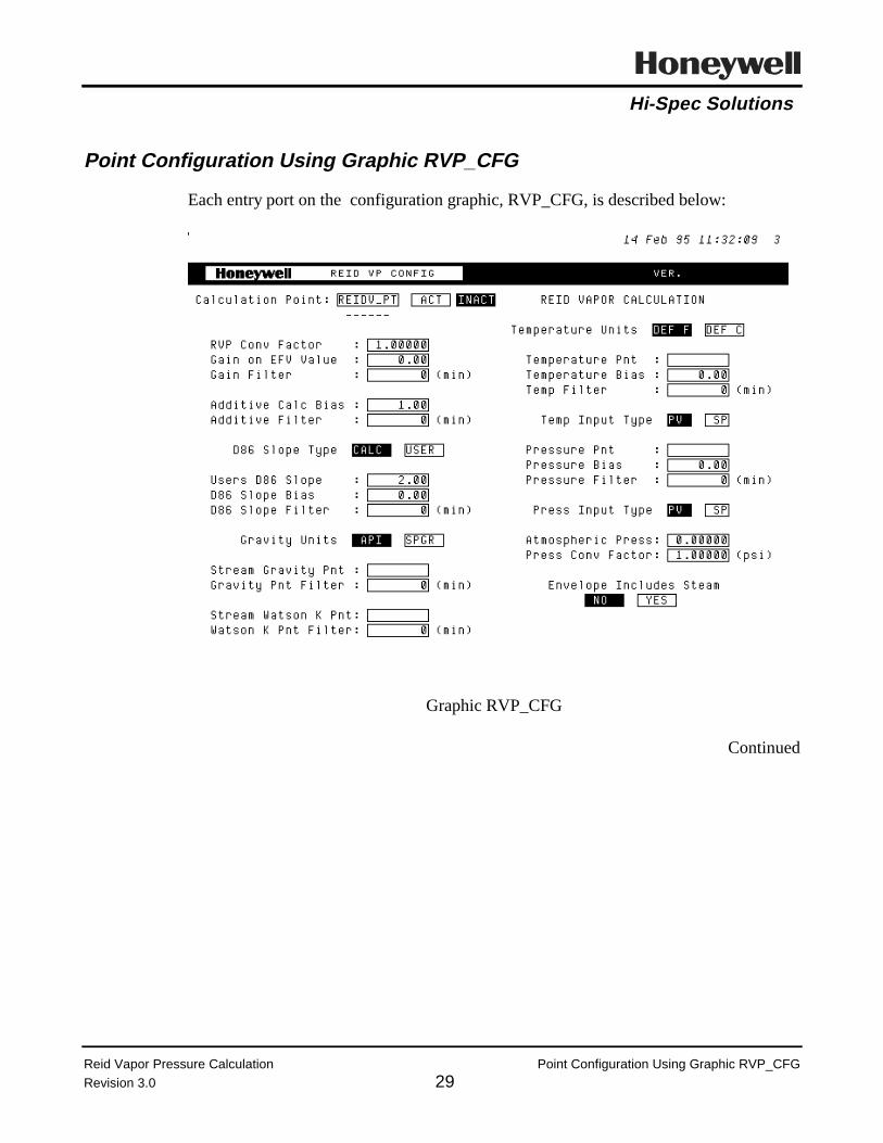
Hi-Spec Solutions
Reid Vapor Pressure Calculation Point Configuration Using Graphic RVP_CFG
Revision 3.0 29
Point Configuration Using Graphic RVP_CFG
Each entry port on the configuration graphic, RVP_CFG, is described below:
Graphic RVP_CFG
Continued
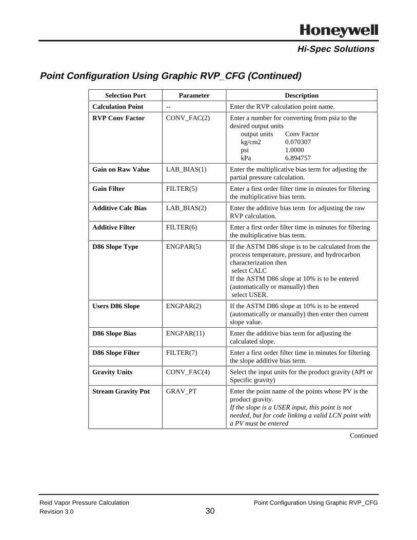
Hi-Spec Solutions
Reid Vapor Pressure Calculation Point Configuration Using Graphic RVP_CFG
Revision 3.0 30
Point Configuration Using Graphic RVP_CFG (Continued)
Selection Port Parameter Description
Calculation Point -- Enter the RVP calculation point name.
RVP Conv Factor CONV_FAC(2) Enter a number for converting from psia to thedesired output units
output units Conv Factorkg/cm2 0.070307psi 1.0000kPa 6.894757
Gain on Raw Value LAB_BIAS(1) Enter the multiplicative bias term for adjusting thepartial pressure calculation.
Gain Filter FILTER(5) Enter a first order filter time in minutes for filteringthe multiplicative bias term.
Additive Calc Bias LAB_BIAS(2) Enter the additive bias term for adjusting the rawRVP calculation.
Additive Filter FILTER(6) Enter a first order filter time in minutes for filteringthe multiplicative bias term.
D86 Slope Type ENGPAR(5) If the ASTM D86 slope is to be calculated from theprocess temperature, pressure, and hydrocarboncharacterization then select CALCIf the ASTM D86 slope at 10% is to be entered(automatically or manually) then select USER.
Users D86 Slope ENGPAR(2) If the ASTM D86 slope at 10% is to be entered(automatically or manually) then enter then currentslope value.
D86 Slope Bias ENGPAR(11) Enter the additive bias term for adjusting thecalculated slope.
D86 Slope Filter FILTER(7) Enter a first order filter time in minutes for filteringthe slope additive bias term.
Gravity Units CONV_FAC(4) Select the input units for the product gravity (API orSpecific gravity)
Stream Gravity Pnt GRAV_PT Enter the point name of the points whose PV is theproduct gravity.If the slope is a USER input, this point is notneeded, but for code linking a valid LCN point witha PV must be entered
Continued

Hi-Spec Solutions
Reid Vapor Pressure Calculation Point Configuration Using Graphic RVP_CFG
Revision 3.0 31
Point Configuration Using Graphic RVP_CFG (Continued)
Selection Port Parameter Description
Gravity Pnt Filter FILTER(3) Enter a first order filter time in minutes for filteringthe gravity input.
Stream Watson K Pnt WATK_PT Enter the point name of the points whose PV is theproduct Watson K.If the slope is a USER input, this point is notneeded, but for code linking a valid LCN point witha PV must be entered
Watson K Pnt Filter FILTER(4) Enter a first order filter time in minutes for filteringthe Watson K input.
Temperature Units CONV_FAC(3) Select the proper input units,(C, or F)
Temperature Bias T_BIAS Enter the bias to the input temperature in theselected units
Temp Filter FILTER(1) Enter the filter time (in minutes) for filtering of theinput temperature
Temp Input Type ENGPAR(6) Select whether the PV or SP of the temperatureinput with be used
Pressure Bias P_BIAS Enter the bias to the input pressure in the same unitsas the input units
Pressure Filter FILTER(2) Enter the filter time (in minutes) for filtering of thepressure inputs
Press Input Type ENGPAR(7) Select whether the PV or SP of the draw pressureinput with be used
Atmospheric Press ENGPAR(1) Enter the atmospheric pressure in input units.If a 0 or negative number is entered14.696 psi is assumedIf a positive number is enteredatmospheric pressure = this number *
the pressure conversion factor
Press Conv Factor CONV_FAC(1) Enter a number for converting from input units topsi
input units Conv Factorkg/cm2 14.223343psi 1.0000kPa 0.145038
Envelope IncludesSteam
ENGPAR(10) If a stripping media is present at the draw tray(steam, nitrogen, Fuel gas) then choose YESOtherwise select NO
Continued

Hi-Spec Solutions
Reid Vapor Pressure Calculation Point Configuration Using Graphic RVP_CFG
Revision 3.0 32
Point Configuration Using Graphic RVP_CFG (Continued)
Selection Port Parameter Description
Temperature Pnt TEMP_PT(1) Leave Blank (NULL) until after code linking
Pressure Pnt PRESS_PT(1) Leave Blank (NULL) until after code linking
Envelope Stm Press(only appears ifEnvelope IncludesSteam is ON )
PRESS_PT(2) Leave Blank (NULL) until after code linking

Hi-Spec Solutions
Reid Vapor Pressure Calculation Point Configuration through Direct CDS Entry
Revision 3.0 33
Point Configuration through Direct CDS Entry
If the configuration graphic is not used, then the configuration data must be entereddirectly onto the point detail of the calculation point. The required calculation pointinformation and associated parameter are listed below.
Parameter Description Comments
TEMP_PT(1) Product Draw Temperature Point Leave Blank (NULL) until after codelinking
TEMP_PT(2) Leave Blank (NULL) until after codelinking
PRESS_PT(1) Product Draw Pressure Point Leave Blank (NULL) until after codelinking
PRESS_PT(2) Stripping Medium partial pressurecalculation point(Used only if the envelopeincludes a stripping media)
Leave Blank (NULL) until after codelinking
GRAV_PT Stream Gravity Point Enter the point name of the pointswhose PV is the product gravity.If the slope is a USER input, this pointis not needed, but for code linking avalid LCN point with a PV must beentered
WATK_PT Stream Watson K Point Enter the point name of the pointswhose PV is the product Watson K.If the slope is a USER input, this pointis not needed, but for code linking avalid LCN point with a PV must beentered
T_BIAS Temperature Bias Enter the bias to the input temperaturein the selected units
P_BIAS Pressure Bias Enter the bias to the input pressure inthe same units as the input units
ENGPAR(1) Atmospheric Press Enter the atmospheric pressure in inputunits.If a 0 or negative number is entered14.696 psi is assumed.If a positive number is enteredatmospheric pressure = this numbertimes the pressure conversion factor
Continued

Hi-Spec Solutions
Reid Vapor Pressure Calculation Point Configuration through Direct CDS Entry
Revision 3.0 34
Point Configuration through Direct CDS Entry (Continued)
Parameter Description Comments
ENGPAR(2) Users D86 Slope If the ASTM D86 slope at 10% is to beentered (automatically or manually)then enter then current slope value
ENGPAR(5) D86 Slope Type If the ASTM D86 slope is to becalculated from the processtemperature, pressure, andhydrocarbon characterization thenenter 0.00If the ASTM D86 slope at 10% is to beentered (automatically or manually)then enter 1.00
ENGPAR(6) Temperature Input Type If the PV of the temperature input is tobe used enter 0.00If the SP of the temperature input is tobe used enter 1.00
ENGPAR(7) Pressure Input Type If the PV of the pressure input is to beused enter 0.00If the SP of the pressure input is to beused enter 1.00
ENGPAR(10) Indicates if the envelope includesa stripping media
If a stripping media is present at thedraw tray (steam, nitrogen, Fuel gas)then enter 1.00Otherwise enter 0.00
ENGPAR(11) ASTM D86 Slope Bias Enter the additive bias term foradjusting the calculated slope.
CONV_FAC(1) Pressure Conversion Factor frominput units to psi
Enter a number for converting frominput units to psi
input units Conv Factorkg/cm2 14.223343psi 1.0000kPa 0.145038
CONV_FAC(2) RVP Conversion Factor from psiato the output units
Enter a number for converting frompsia to the desired output units
output units Conv Factorkg/cm2 0.070307psi 1.0000kPa 6.894757
CONV_FAC(3) Temperature Units For F input enter 0.00For C input enter 1.00

Hi-Spec Solutions
Reid Vapor Pressure Calculation Point Configuration through Direct CDS Entry
Revision 3.0 35
Point Configuration through Direct CDS Entry (Continued)
Parameter Description Comments
CONV_FAC(4) Gravity Units For API input enter 0.00For Specific gravity input
enter 1.00
FILTER(1) Temperature Filter Enter the filter time (in minutes) forfiltering of the input temperature
FILTER(2) Pressure Filter Enter the filter time (in minutes) forfiltering of the pressure inputs
FILTER(3) Gravity Point Filter Enter a first order filter time in minutesfor filtering the gravity input.
FILTER(4) Watson K Point Filter Enter a first order filter time in minutesfor filtering the Watson K input.
FILTER(5) Gain Filter Enter a first order filter time in minutesfor filtering the multiplicative biasterm.
FILTER(6) Additive Filter Enter a first order filter time in minutesfor filtering the multiplicative biasterm.
FILTER(7) D86 Slope Filter Enter a first order filter time in minutesfor filtering the slope additive biasterm.
LAB_BIAS(1) Gain on System Partial Pressure Enter the multiplicative bias term foradjusting the partial pressurecalculation.
LAB_BIAS(2) Additive Calculation Bias Enter the additive bias term foradjusting the raw RVP calculation.

Hi-Spec Solutions
Reid Vapor Pressure Calculation Link CL Programs
Revision 3.0 36
Link CL Programs
Step Action
Link REID_VP From the Command Processor Display:
LK $Fn>AO>REID_VP point_name [ENTER]

Hi-Spec Solutions
Reid Vapor Pressure Calculation Input Configuration Using Graphic RVP_CFG
Revision 3.0 37
Input Configuration Using Graphic RVP_CFG
Call up the schematic RVP_CFG.
Selection Port Parameter Description
Temperature Pnt TEMP_PT(1) Enter the point name of the draw temperature
Pressure Pnt PRESS_PT(1) Enter the Point name of the product draw pressure.
Envelope Stm Press(only appears ifEnvelope IncludesSteam is ON )
PRESS_PT(2) If used,Enter the point name whose PV is the strippingmedia partial pressure

Hi-Spec Solutions
Reid Vapor Pressure Calculation Input Configuration through Direct CDS Entry
Revision 3.0 38
Input Configuration through Direct CDS Entry
If the configuration graphic is not used, then entered the input point names directly ontothe point detail of the calculation point.
Parameter Description Comments
TEMP_PT(1) Product Draw Temperature Point Enter the point name of the drawtemperature
TEMP_PT(2) Leave Blank (NULL)
PRESS_PT(1) Product Draw Pressure Point Enter the Point name of the productdraw pressure.
PRESS_PT(2) Stripping Medium partial pressurecalculation point(Used only if the envelopeincludes a stripping media)
If used,Enter the point name whose PV is thestripping media partial pressure

Hi-Spec Solutions
Reid Vapor Pressure Calculation Activate Point
Revision 3.0 39
Activate Point
Step Action
Activate point Call up the point detail and activate the point, or activate from RVP_CFGgraphic.
Verify Operation Verify that REID_VP is running without any CL errors.

Hi-Spec Solutions
Reid Vapor Pressure Calculation Appendix A Engineer’s Detailed DescriptionRevision 3.0 40

Hi-Spec Solutions
Honeywell Hi-Spec Solutions • 16404 N. Black Canyon Hwy. • Phoenix, AZ 85023
Advanced Control Package
Temperature Corrected Specific Gravity
CONTROLLED
March 1995Revision 2.0

Hi-Spec Solutions
Temperature Corrected Specific Gravity Contents
Revision 2.0
Table of Contents
Overview.........................................................................................................................................1
Acronym List ..................................................................................................................................3
Hardware and Software Requirements ...........................................................................................4
Instrumentation (Process Inputs) ....................................................................................................5
Process Diagram .............................................................................................................................6
Detailed Description .......................................................................................................................7
Point Structure ..................................................................................................................8
Process Inputs ...................................................................................................................9
Configuration Inputs .......................................................................................................10
Calculation Outputs ........................................................................................................11
Error Codes ...................................................................................................................................12
Diagnostic Error Codes...................................................................................................13
Filter Subroutine Error Codes.........................................................................................14
Configuration and Tuning.............................................................................................................15
Biases in the Temperature Corrected Specific Gravity Program....................................16
Tuning Parameters ..........................................................................................................17
Algorithms ....................................................................................................................................18
Installation Procedure ...................................................................................................................20
Preparation for Installation .............................................................................................21
Custom Data Segment (CDS) and Parameter List (PL) Installation...............................22
Building Application Module Point................................................................................23
Configuration Graphics Installation................................................................................24
Configure Calculation Point .........................................................................................................25
Point Configuration Using Graphic ................................................................................26
Point Configuration through Direct CDS Entry..............................................................27
Link CL Programs...........................................................................................................................1

Hi-Spec Solutions
Temperature Corrected Specific Gravity Revision History
Revision 2.0


Hi-Spec Solutions
Temperature Corrected Specific Gravity Overview
Revision 2.0 1
Overview
Definition. The temperature corrected specific gravity is the specific gravity of a liquidhydrocarbon stream at the flowing or process temperature.
Application. The temperature corrected specific gravity of a liquid hydrocarbon streamis used to determine the stream’s mass flow.
Calculation. The temperature corrected specific gravity program calculates the flowingspecific gravity of a liquid hydrocarbon stream based on:
• Processinputs :
Temperature
• Characterizationinputs:
Watson K and gravity at 60 °F
• Calculatedvalues:
Temperature corrected specific gravity, andconvert input gravity to specific gravity.
Incentive. 1. To provide required information for calculating the mass flow of aliquid hydrocarbon stream.
2. To provide a real-time input for use in advanced control applications.
3. To provide physical property estimations.

Hi-Spec Solutions
Temperature Corrected Specific Gravity Overview
Revision 2.0 2
Temperature Corrected Gravity
0.7000
0.8000
0.9000
0 20 40 60 80 100 120 140 160 180 200
Temperature, Deg F
Sp
ecif
ic G
ravi
ty
Lab Grav
Temp Corr Grav
Figure 1
Figure 1 shows the relationship between a specific gravity at 60 °F (Lab Grav) and thetemperature corrected specific gravity. As would be expected the temperature correctedgravity is less than the lab gravity above 60 F and grater than the lab gravity below 60F. The ASTM D1289-85 Density, Relative Density (Specific Gravity), or API Gravityof Crude Petroleum and Liquid Petroleum Products by Hydrometer Method, or similarmethod is presumed to be the means of determining the lab gravity.

Hi-Spec Solutions
Temperature Corrected Specific Gravity Acronym List
Revision 2.0 3
Acronym List
Term Acronym
Application Module AM
Local Control Network LCN
Universal Station US
control language CL
process variable PV
custom data segment CDS
pounds per square inch psi
Parameter List PL
CL object code file extension AO

Hi-Spec Solutions
Temperature Corrected Specific Gravity Hardware and Software Requirements
Revision 2.0 4
Hardware and Software Requirements
Requirement Description
Hardware Platform TDC 3000 AM
Special Boards None
Other Computing Systems None
LCN Release Release 300 or later
AM Load Modules None
US Load Modules None
Other Packages None
Other Control Applications None
Software Inputs The gravity input and Watson K factor for the liquid hydrocarbonstream must exist as points on the LCN

Hi-Spec Solutions
Temperature Corrected Specific Gravity Instrumentation (Process Inputs)
Revision 2.0 5
Instrumentation (Process Inputs)
Process Input1 Required Recommended
Stream temperature X
1 Required inputs can sometimes be obtained by inference. However, calculations based upon inferred data can be less accurate than calculations based upon direct readings.

Hi-Spec Solutions
Temperature Corrected Specific Gravity Process Diagram
Revision 2.0 6
Process Diagram
TI
FC
FLOW
Typical Flow Controller

Hi-Spec Solutions
Temperature Corrected Specific Gravity Detailed Description
Revision 2.0 7
Detailed Description
The tables in this section describe the following specific gravity correction programarchitecture:
• Point Structure
• Process Inputs
• Configuration Inputs
• Calculation Outputs.

Hi-Spec Solutions
Temperature Corrected Specific Gravity Point Structure
Revision 2.0 8
Point Structure
Point Structure
Point Type Application Module Regulatory
PV_Type FLOWCOMP
CTL_Type Any
Custom Data Segment SG_CDS.CL
Algorithm SG_CORR.CL
Insertion Point PRE_GI
Slot 5
Output The temperature corrected specific gravity is stored to the CDSCALC_VAL(1)

Hi-Spec Solutions
Temperature Corrected Specific Gravity Process Inputs
Revision 2.0 9
Process Inputs
Process Inputs
Critical2
Parameter Description Units Yes No
GRAV_PT Tagname of source for the liquidhydrocarbon stream’s gravity
°API or none (S.G.)X
TEMP_PT Tagname of source for the liquidhydrocarbon stream’s temperature at theflow meter
°F or °CX
WATK_PT Tagname of source for the liquidhydrocarbon stream’s Watson K factor
NoneX
.
2 Critical indicates that a bad input causes the output of the calculation to be set BAD.

Hi-Spec Solutions
Temperature Corrected Specific Gravity Configuration Inputs
Revision 2.0 10
Configuration Inputs
Configuration Inputs
Parameter Description Units
CONV_FAC(1) Input temperature unit flag; 0 => °F;1 => °C
N/A
CONV_FAC(2) Input gravity type flag:0 => API;1 => Specific gravity
N/A
ENGPAR Flag to force calculation BAD( 0 => Do not set BAD; 1 => Set calculation BAD)
N/A
FILTER(1) Filter time for the liquid hydrocarbon stream’s gravity Minutes
FILTER(2) Filter time for the liquid hydrocarbon stream’s temperatureat the flow meter
Minutes
FILTER(3) Filter time for the liquid hydrocarbon stream’s Watson Kfactor
Minutes
T_BIAS Additive bias to the liquid hydrocarbon stream’stemperature at the flow meter
Same units asTEMP_PT

Hi-Spec Solutions
Temperature Corrected Specific Gravity Calculation Outputs
Revision 2.0 11
Calculation Outputs
Calculation Outputs
Parameter Description Units
CALC_VAL(1) Liquid hydrocarbon stream’s temperature corrected specificgravity
N/A
CALC_VAL(2) Input gravity converted to a specific gravity N/A
CALC_VAL(3) The liquid hydrocarbon stream’s temperature at the flowmeter plus additive temperature bias
°F
FILT_VAL(1) Filtered value of the liquid hydrocarbon stream’s gravity Input units
FILT_VAL(2) Filtered value of the liquid hydrocarbon stream’stemperature at the flow meter
Input units
FILT_VAL(3) Filtered value of the liquid hydrocarbon stream’s Watson Kfactor
Input units
REV_NO Program revision number N/A
STATUS(1) Diagnostic error location indication N/A
STATUS(2) Diagnostic indication of subroutine error N/A

Hi-Spec Solutions
Temperature Corrected Specific Gravity Error Codes
Revision 2.0 12
Error Codes
The tables in this section describe the following program error codes:
• Diagnostic error codes
• Filter subroutine error codes.

Hi-Spec Solutions
Temperature Corrected Specific Gravity Diagnostic Error Codes
Revision 2.0 13
Diagnostic Error Codes
Diagnostic Error Codes
Parameter Value Meaning
STATUS(1)3 0.0 No errors
1.0 TEMP_PT has a null point entered or has a bad PV
2.0 GRAV_PT has a null point entered or has a bad PV
3.0 WATK_PT has a null point entered or has a bad PV
4.0 The filtering subroutine has detected a BAD value for the currenttemperature input plus bias
5.0 The filtering subroutine has detected a BAD value for the currentgravity input
6.0 The filtering subroutine has detected a BAD value for the currentWatson K factor input
7.0 The liquid hydrocarbon stream’s temperature at the flow meterplus additive bias is ≤ 0.0
8.0 The liquid hydrocarbon stream’s Watson K factor input is ≤ 0.0
9.0 The liquid hydrocarbon stream’s gravity input is < 0.495
10.0 The liquid hydrocarbon stream’s gravity input is > 1.200
11.0 The absolute difference between the liquid hydrocarbon streamsWatson K factor and 8.5 is < 0.0
12.0 The temperature corrected specific gravity has a BAD value
3 STATUS(1) indicates errors in the calculation.

Hi-Spec Solutions
Temperature Corrected Specific Gravity Filter Subroutine Error Codes
Revision 2.0 14
Filter Subroutine Error Codes
Filter Subroutine Error Codes
Parameter Value Meaning
STATUS(2)4 0.0 No errors
1.0 The filtering subroutine current value input has a BAD value
4 STATUS(2) indicates errors returned by the filtering subroutine.

Hi-Spec Solutions
Temperature Corrected Specific Gravity Configuration and Tuning
Revision 2.0 15
Configuration and Tuning
This section describes the parameters and values used to configure and tune the packageto a specific application.
Biases
• Temperature Bias
Tuning
• None.

Hi-Spec Solutions
Temperature Corrected Specific Gravity Biases in Temperature Corrected Specific Gravity Program
Revision 2.0 16
Biases in the Temperature Corrected Specific Gravity Program
The temperature corrected specific gravity program is equipped with the followingadditive biases:
• Temperature at the flow meter input.
Bias Parameters
Parameter Description
T_BIAS Additive bias to the liquid hydrocarbon stream’s temperature at the flowmeter input, TEMP_PT
Temperature Bias. The temperature bias (T_BIAS) is added to the input valuesbefore performance of the unit conversions and should be entered in the same units asthe input temperature.
The T_BIAS parameter is used when there is a known error in either the liquidhydrocarbon stream’s temperature at the flow meter indication.

Hi-Spec Solutions
Temperature Corrected Specific Gravity Tuning Parameters
Revision 2.0 17
Tuning Parameters
There are no tuning parameters associated with liquid hydrocarbon stream’stemperature corrected specific gravity program.

Hi-Spec Solutions
Temperature Corrected Specific Gravity Algorithms
Revision 2.0 18
Algorithms
Conversion of Engineering Units. The input process temperature can be in Fahrenheitor Centigrade. However, temperatures in °C are converted to °F for internal use asshown in Equation 1:
temp = (TEMP_PT.PV + T_BIAS) * 1.8 + 32
Where:
temp = Process temperature converted to °F for internal useT_BIAS = Temperature input bias in °CTEMP_PT.PV = Input process temperature in °C
Equation 1
The gravity input can be in °API or specific gravity. However, °API inputs areconverted to specific gravity for internal use as shown in Equation 2:
f_grav = 141.5 / (GRAV_PT.PV + 131.5)
Where:
f_grav = Gravity input converted to specific gravity for internal useGRAV_PT.PV = Input gravity in °API
Equation 2
Continued

Hi-Spec Solutions
Temperature Corrected Specific Gravity Algorithms
Revision 2.0 19
Algorithms (Continued)
Temperature Corrected Specific Gravity. The temperature corrected specific gravityis calculated from process inputs using the calculation as shown in Equation 3:
corr_spgr = Function[stream_spgr, stream_watk, stream _t]
Where:
corr_spgr = Liquid hydrocarbon stream’s temperature corrected specificgravity
stream_spgr = Liquid hydrocarbon stream’s specific gravity @60 °Fstream_watk = Liquid hydrocarbon stream’s Watson K factorstream_t = Liquid hydrocarbon stream’s temperature at the flow meter
Equation 3
Note: The liquid hydrocarbon stream’s base specific (stream_spgr) gravity is presumedto be the specific gravity at 60 °F. For a base gravity at a different temperature, thebase gravity must be converted to a gravity at 60 °F before being provided to thetemperature corrected specific gravity procedure.

Hi-Spec Solutions
Temperature Corrected Specific Gravity Installation Procedure
Revision 2.0 20
Installation Procedure
This document describes the installation procedure for SG_CORR on the TDC 3000System AM.
This section covers the following topics:
• Preparation for Installation
• Custom Data Segment (CDS) and Parameter List (PL) Installation
• Building Application Module Point
• Configuration Graphics Installation.

Hi-Spec Solutions
Temperature Corrected Specific Gravity Preparation for Installation
Revision 2.0 21
Preparation for Installation
Step Action
Gather media Gather the following items:
• Removable media containing the directory GRAV
Make media backup Make a backup copy of media/directory on a US with drives n and mconfigured as follows:
Media:
FCOPY $Fn $Fm
Directory only:
CD $Fm>CALC> GRAV (PICTURE FILE)
CD $Fm>CALC> CDS (CDS FILE)
CD $Fm>CALC> AO (PROGRAM FILE)
CD $Fm>CALC> EB (PROGRAM FILE)
COPY $Fn>GRAV>*.* $Fm>GRAV>= -V -D
COPY $Fn>CDS>*.* $Fm>CDS>= -V -D
COPY $Fn>AO>*.* $Fm>AO>= -V -D
COPY $Fn>EB>*.* $Fm>AO>= -V -D
Where $Fn is the drive with the source media and $Fm is the drive withthe target media.

Hi-Spec Solutions
Temperature Corrected Specific Gravity CDS and PL Installation
Revision 2.0 22
Custom Data Segment (CDS) and Parameter List (PL) Installation
This procedure must be done once per LCN installation.
Step Action
Set volumepathnames
From Modify Volume Paths display:
CL CUSTOM GDF: NET>CDSG>
USER DEFLT PATH: $Fn>CDS
Compile SG_CDS.CL From the Command Processor Display, compile the CDS file, SG_CDS:
CL $Fn>CDS>SG_CDS.CL -UL
If it is necessary to change the CDS due to a software revision, refer to the CData Control Language/Application Module Data Entry
Parameter list There is no parameter list for the standard temperature corrected specificgravity package

Hi-Spec Solutions
Temperature Corrected Specific Gravity Building Application Module Point
Revision 2.0 23
Building Application Module Point
An AM point is required for each temperature corrected specific gravity. The AM pointthat does the temperature corrected specific gravity also calculates the liquidhydrocarbon stream’s mass flow. The PV algorithm of the AM point is flowcompensation (FLOWCOMP) using Equation A and the point’s parameters areconfigured as indicated below:
C = Scaling factorC1 = Design specific gravity @60 °FC2 = Set to default value, 1.0F = The flow inputG = Temperature corrected specific gravityRG = Design specific gravity at flowing temperature.
The temperature corrected specific gravity is transfers from CDS to the flowcompensation parameter via a general input. Build the AM point as follows:
Step Action
Modify ExceptionBuild file,SG_CORR.EB
From the Command Processor Display:
ED $Fn>EB>SG_CORR.EB [ENTER]
Edit template as follows:
&N point name
UNIT = unit number
PTDESC ="point descriptor text"
KEYWORD = "keyword"
PERIOD = as required
Load EB file. From the Builder Commands Display:
Select the EXCEPTION BUILD target.
Fill in ports as:
REFERENCE PATH NAME: $Fn>EB
Load Entities (select target)
Pathname for SOURCE file: SG_CORR.EB
Pathname for IDF file: SG_CORR.DB
[ENTER]
Verify load When the load is complete, verify point loading by calling the point detailfrom the [DETAIL] button.

Hi-Spec Solutions
Temperature Corrected Specific Gravity Configure Graphics Installation
Revision 2.0 24
Configuration Graphics Installation
There is no configuration graphic for the temperature corrected specific gravity.

Hi-Spec Solutions
Temperature Corrected Specific Gravity Configure Calculation Point
Revision 2.0 25
Configure Calculation Point
Configuration of the temperature corrected specific gravity point must be done throughdirect entry to the CDS ports on the Point Detail display.
• Non Graphic Configuration of Temperature Corrected Specific Gravity Point
• Linking CL Program.

Hi-Spec Solutions
Temperature Corrected Specific Gravity Point Configuration Using Graphic
Revision 2.0 26
Point Configuration Using Graphic
There is no configuration graphic for the temperature corrected specific gravity.

Hi-Spec Solutions
Temperature Corrected Specific Gravity Point Configuration through Direct CDS Entry
Revision 2.0 27
Point Configuration through Direct CDS Entry
The required calculation point information and associated parameters are listed below.
Parameter Description Comments
CONV_FAC(1) Input temperature unit flag: 0 =>°F ;1 => °C
Default is 0 (°F).
CONV_FAC(2) Input gravity type flag0 => API ;1 => Specific gravity
Default is 0 (API).
FILTER(1) Filter time for the liquidhydrocarbon stream’s gravity
Minutes
FILTER(2) Filter time for the liquidhydrocarbon stream’s temperature
Minutes
FILTER(3) Filter time for the liquidhydrocarbon stream’s Watson Kfactor
Minutes
GRAV_PT Tagname of source for the liquidhydrocarbon stream’s gravity
This is the lab gravity at @60 °F.
TEMP_PT Tagname of source for the liquidhydrocarbon stream’s temperature
The temperature must be the liquidhydrocarbon stream’s temperaturewhere the flow is measured.
T_BIAS Additive bias to the liquidhydrocarbon stream’s temperature
Same units as TEMP_PT.
WATK_PT Tagname of source for the liquidhydrocarbon stream’s Watson Kfactor
Build an AM numeric point to hold amanually input value.
Or the Watson K can be calculatedusing the stream’s ASTM D8610%;50%; & 90% points and gravity.This requires an AM REG_PV pointand the Watson K CL code.

Hi-Spec Solutions
Temperature Corrected Specific Gravity Appendix A Engineer’s Detailed Description
Revision 2.0 A-1
Link CL Programs
Step Action
Link SG_CORR From the Command Processor Display:
LK $Fn>AO>SG_CORR point_name [ENTER]
Activate point Call up the point detail and activate the point.
Verify Operation Verify that SG_CORR is running without any CL errors.


Hi-Spec Solutions
Honeywell Hi-Spec Solutions • 16404 N. Black Canyon Hwy. • Phoenix, AZ 85023
Advanced Control Package
Watson K Calculation
CONTROLLED
March 1995Revision 3.0

Hi-Spec Solutions
Watson K Calculation Revision History
Revision 2.0

Hi-Spec Solutions
Watson K Calculation Contents
Revision 2.0
Table of Contents
Overview.........................................................................................................................................1
Acronym List ..................................................................................................................................2
Hardware and Software Requirements ...........................................................................................3
Laboratory Inputs............................................................................................................................4
Detailed Description .......................................................................................................................5
Point Structure ..................................................................................................................6
Process Inputs ...................................................................................................................7
Configuration Inputs .........................................................................................................8
Calculation Outputs ..........................................................................................................9
Diagnostic Error Codes.................................................................................................................10
Configuration and Tuning.............................................................................................................11
Biases in the Watson K Program ....................................................................................12
Algorithms ....................................................................................................................................13
Installation Procedure ...................................................................................................................15
Preparation for Installation .............................................................................................16
Custom Data Segment (CDS) Installation ......................................................................17
Building Watson K Calculation Point ............................................................................18
Configure Calculation Point .........................................................................................................19
Point Configuration through Direct CDS Entry..............................................................20
Link CL Programs.........................................................................................................................21
References.....................................................................................................................................22

Hi-Spec Solutions
Watson K Calculation Overview
Revision 2.0 1
Overview
Definition. The Watson characterization factor, K, is the quotient of the cube root ofthe mean average boiling point and the specific gravity of a hydrocarbon mixture. It isan indication of the paraffinicity of a hydrocarbon mixture and its value is directlyrelated to the degree of saturation.
Application. This program calculates the Watson K of a petroleum stream. It is afundamental characterization parameter used in many calculations. Other Honeywellroutines using Watson K include L&V Gen, Flash, and D86.
Calculation. The Watson K calculation program calculates the inferential Watson K ofa petroleum stream based on:
• Processinputs :
None
• Labinputs:
ViscositySpecific Gravity 60/60°FASTM D86 Temperatures
• Calculatedvalues:
Internally calculated mean average boiling point,and kinematic viscosity.
Incentive. 1. To indicate how closely a hydrocarbon stream is meeting the Watson Kspecification.
2. To eliminate dead time associated with laboratory analysis and on-lineanalyzers.
3. To provide a real-time input for use in advanced control applications.

Hi-Spec Solutions
Watson K Calculation Acronym List
Revision 2.0 2
Acronym List
Term Acronym
Application Module AM
Local Control Network LCN
Universal Station US
control language CL
process variable PV
custom data segment CDS
pounds per square inch psi
Parameter List PL
CL object code file extension AO
Universal Control Network UCN

Hi-Spec Solutions
Watson K Calculation Hardware and Software Requirements
Revision 2.0 3
Hardware and Software Requirements
Requirement Description
Hardware Platform TDC 3000 AM
Special Boards None
Other Computing Systems None
LCN Release Release 300 or later
AM Load Modules None
US Load Modules None
Other Packages None
Other Control Applications None
Software Inputs Specific gravities and viscosity (optional) must exist as points on theUCN

Hi-Spec Solutions
Watson K Calculation Laboratory Inputs
Revision 2.0 4
Laboratory Inputs
Process Input1 Required Recommended
Gravity (API or Specific) X
Viscosity X23
ASTM D86 10% X3
ASTM D86 50T X3
ASTM D86 90% X3
1 Required inputs can sometimes be obtained by inference. However, calculations based upon inferred data can be less accurate than calculations based upon direct readings.2 Prediction accuracy is reduced if this variable is established.3 D86 values or viscosity is required.

Hi-Spec Solutions
Watson K Calculation Detailed Description
Revision 2.0 5
Detailed Description
The tables in this section describe the following Watson K program architecture:
• Point Structure
• Process Inputs
• Configuration Inputs
• Calculation Outputs.

Hi-Spec Solutions
Watson K Calculation Point Structure
Revision 2.0 6
Point Structure
Point Structure
Point Type Application Module Regulatory, CL
PV_Type CL
CTL_Type Any
Custom Data Segment WATK_CDS.CL
Algorithm WATK.CL
Insertion Point PV_ALG
Slot 3
Output The calculated Watson K is displayed as the point’s PV

Hi-Spec Solutions
Watson K Calculation Process Inputs
Revision 2.0 7
Process Inputs
Process Inputs
Critical4
Parameter Description Units Yes No
GRAV_PT Tagname of source for gravity °API or none (S.G.)X
VISC_PT(1) Tagname of source for process viscosity Any valid units ofviscosity
X
VISC_PT(2) Required for CL link None X
.
4 Critical indicates that a bad input causes the output of the calculation to be set BAD.

Hi-Spec Solutions
Watson K Calculation Configuration Inputs
Revision 2.0 8
Configuration Inputs
Configuration Inputs
Parameter Description Units
ENGPAR(1) The ASTM D86 distillation temperature at 10% volumepercent distilled
°F or °C
ENGPAR(2) The ASTM D86 distillation temperature at 50% volumepercent distilled
°F or °C
ENGPAR(3) The ASTM D86 distillation temperature at 90% volumepercent distilled
°F or °C
ENGPAR(4) Mean average boiling point bias °F or °C
ENGPAR(5) Spare
CONV_FAC(1) Input temperature units( 0 => °F; 1 => °C)
N/A
CONV_FAC(2) Input gravity units( 0 => API, 1 => SPGR )
N/A
CONV_FAC(3) Input viscosity units can be absolute or kinematic.( 0 => Cp, 1 => Cs)
N/A
CONV_FAC(4) Conversion factor for an input viscosity that is not in Cp orCs
Cp or CS per unitof input viscosity
CONV_FAC(5) Spare N/A

Hi-Spec Solutions
Watson K Calculation Calculation Outputs
Revision 2.0 9
Calculation Outputs
Calculation Outputs
Parameter Description Units
PVCALC Calculated Watson K None
CALC_VAL(1) Calculated Watson K None
CALC_VAL(2) Mean average boiling point °F or °C
CALC_VAL(3) Calculated kinematic viscosity Cs
CALC_VAL(4) Spare
STATUS Diagnostic error codes giving location and possible causes ofprogram error
N/A
REV_NO Program revision number N/A

Hi-Spec Solutions
Watson K Calculation Diagnostic Error Codes
Revision 2.0 10
Diagnostic Error Codes
This table describes program error codes found in the CDS parameter STATUS(1):
Diagnostic Error Codes
Parameter Value Meaning
STATUS(1)5 0.0 No errors
1.0 GRAV_PT is null or has a bad PV
2.0 The D86 10% temperature is bad
3.0 The D86 50% temperature is bad
4.0 The D86 90% temperature is bad
5.0 The 10% temperature is greater than the 90% temperature.
6.0 The 50% temperature is greater than the 90% temperature
7.0 GRAV_PT has a bad PV
8.0 VISC_PT(1) has a bad PV
9.0 Iterative to estimate Watson K using API 11a4.1-3 did notconverge
10.0 Iterative estimate of flowing specific gravity did not converge
5 STATUS(1) indicates errors in the calculation.
Hi-Spec Solutions
Watson K Calculation Configuration and Tuning
Revision 2.0 11
Configuration and Tuning
This section describes the parameters and values used to configure and tune the packageto a specific application.
Biases
• Mean Average Boiling Point Bias
Tuning
• No adjustable tuning parameters are provided.

Hi-Spec Solutions
Watson K Calculation Biases in the Watson K Program
Revision 2.0 12
Biases in the Watson K Program
The Watson K program is equipped with a mean Average Boiling Point Bias.
Bias Parameters
Parameter Description
ENGPAR(4) An additive bias on the result of the mean average boiling pointcalculation, in degrees Fahrenheit.

Hi-Spec Solutions
Watson K Calculation Algorithms
Revision 2.0 13
Algorithms
The calculations are preceded by engineering unit conversions.
Engineering Unit Conversions
Unit Format
Temperature The mean average boiling point calculation uses temperature inFahrenheit and converts the result to degrees Rankine.
Gravity The algorithm uses both API gravity and specific gravity. The missinggravity is obtained from the definition of API gravity.
API gravity = 141.5/specific gravity (60F/60F) - 131.5
Viscosity If an absolute viscosity is entered, a flowing specific gravity at 210°F iscalculated and used in the conversion to kinematic viscosity.
Watson K Calculation
When the user provides the ASTM D86 distillation temperatures at the 10%, 50%, and90% volume distilled points, a mean average boiling point can be calculated by APIProcedure 2B1.1. The Watson K is then calculated directly from API 2-0.8.
KMeABP
spgr= ( ) /1 3
Where:
K = Calculated Watson KMeABP = Mean Average Boiling Pointspgr = Specific Gravity, 60F / 60F
Equation 1

Hi-Spec Solutions
Watson K Calculation Algorithms
Revision 2.0 14
Watson K Calculation (Continued)
When the user does not provide distillation temperatures, but uses measured viscosity,the Watson K is calculated iteratively. The convergence criteria is based on thedifference between measured and calculated viscosities. API equation 11A4.1-3 and itsfirst derivative are used to update the Watson K estimate on each iteration.
watson watsonvisc visc calc
visc prime= + −( _ )
_
Where:
Watson = Estimated Watson Kvisc = Measured kinematic viscosity, Cs.visc_calc = Kinematic viscosity calculated from API 11A4.1-3visc_prime = First derivative of API 11A4.1-3 evaluated using
estimated Watson K
Equation 2
Flowing Specific Gravity Calculation
If the user provides an absolute viscosity, the current estimate of the Watson K and thespecific gravity are used to determine a flowing specific gravity at 210°F. A measuredkinematic viscosity is then based on this flowing specific gravity.
The flowing specific gravity equation is a polynomial fit to a nomograph by Ritter et aland it is solved by iteration. The Watson K iteration described above is nested withinthe specific gravity iteration. The difference between the current and previous WatsonK values must be less than 0.05 for the flowing specific gravity iteration to converge.

Hi-Spec Solutions
Watson K Calculation Installation Procedure
Revision 2.0 15
Installation Procedure
This document describes the installation procedure for WATK on the TDC 3000System AM.
This section covers the following topics:
• Preparation for Installation
• Custom Data Segment (CDS) Installation
• Building a Watson K Calculation Point.

Hi-Spec Solutions
Watson K Calculation Preparation for Installation
Revision 2.0 16
Preparation for Installation
Step Action
Gather media Gather the following items:
• Removable media containing the directory WATK
• Commissioning Worksheet
Make media backup Make a backup copy of media/directory on a US with drives n and mconfigured as follows:
Media:
FCOPY $Fn $Fm
Directory only:
CD $Fm>vol_dir> WATK
CD $Fm>vol_dir> CDS
CD $Fm>vol_dir> AO
CD $Fm>vol_dir> EB
COPY $Fn>WATK>*.* $Fm>WATK>= -V -D
COPY $Fn>CDS>*.* $Fm>CDS>= -V -D
COPY $Fn>AO>*.* $Fm>AO>= -V -D
COPY $Fn>EB>*.* $Fm>EB>= -V -D
Where $Fn is the drive with the source media and $Fm is the drive withthe target media.

Hi-Spec Solutions
Watson K Calculation CDS Installation
Revision 2.0 17
Custom Data Segment (CDS) Installation
This procedure must be done once per LCN installation.
Step Action
Set volumepathnames
From Modify Volume Paths display:
CL CUSTOM GDF: NET>CDSG>
USER DEFLT PATH: $Fn>CDS
CompileWATK_CDS.CL
From the Command Processor Display, compile the CDS file, WATK_CDS:
CL $Fn>CDS>WATK_CDS.CL -UL
If it is necessary to change the CDS due to a software revision, refer to theApplication Module Data Control Language/Application Module Data Entry

Hi-Spec Solutions
Watson K Calculation Building Watson K Calculation Point
Revision 2.0 18
Building Watson K Calculation Point
A calculation point is required for each hydrocarbon Watson K calculated.
Step Action
Modify ExceptionBuild file,WATK_PNT.EB
From the Command Processor Display:
ED $Fn>EB>WATK_PNT.EB [ENTER]
Edit template as follows:
&N point name
UNIT = unit number
PTDESC ="point descriptor text"
KEYWORD = "keyword"
PERIOD = as required
Load EB file. From the Builder Commands Display:
Select the EXCEPTION BUILD target.
Fill in ports as:
REFERENCE PATH NAME: $Fn>EB
Load Entities (select target)
Pathname for SOURCE file: WATK_PNT.EB
Pathname for IDF file: WATK_PNT.DB
[ENTER]
Verify load When the load is complete, verify point loading by calling the point detailfrom the [DETAIL] button.

Hi-Spec Solutions
Watson K Calculation Configure Calculation Point
Revision 2.0 19
Configure Calculation Point
Configuration of the calculation point must be done through direct entry to the CDSports on the Point Detail display. Configuration consists of the following steps.
• Non Graphic Configuration of Watson K Calculation Point
• Linking CL Program.

Hi-Spec Solutions
Watson K Calculation Point Configuration through Direct CDS Entry
Revision 2.0 20
Point Configuration through Direct CDS Entry
The required calculation point information and associated parameter are listed below.
Parameter Description Comments
GRAV_PT Tagname of point for lab gravity Usually a lab entry point
VISC_PT(1) Tagname of point for lab viscosity Usually a lab entry point
ENGPAR(1) ASME D86 dist. temp. at 10%volume distilled.
Units must be consistent with others andit must be the lowest temperature.
ENGPAR(2) ASME D86 dist. temp. at 50%volume distilled.
Units must be consistent with others andit must be between the othertemperatures.
ENGPAR(3) ASME D86 dist. temp. at 90%volume distilled.
Units must be consistent with others andit must be the highest temperature.
ENGPAR(4) Mean average boiling pointadditive bias.
Bias is in Celsius or Fahrenheit. It isadded to the MeABP before it isconverted to Rankine.
ENGPAR(5) Spare
CONV_FAC(1) Input temperature units flag 0 = Fahrenheit
1 = Celsius
CONV_FAC(2) Flag to indicate type of inputgravity
0 = API
1 = Specific Gravity (60F / 60 F)
CONV_FAC(3) Flag to indicate absolute orkinematic viscosity
0 = Absolute
1 = Kinematic
CONV_FAC(4) Conversion factor for an inputviscosity that is not in Cp or Cs.Default to 1.0 if input in Cp or Cs.
Example:If input viscosity = lbs-sec/in2
And CONV_FAC(3) = 0 (Cp)Then CONV_FAC(4) = 6.897×10⁻⁴.
CONV_FAC(5) Spare

Hi-Spec Solutions
Watson K Calculation Link CL Programs
Revision 2.0 21
Link CL Programs
Step Action
Link WATK From the Command Processor Display:
LK $Fn>AO>WATK point_name [ENTER]
Activate point Call up the point detail and activate the point.
Verify Operation Verify that WATK is running without any CL errors.

Hi-Spec Solutions
Watson K Calculation References
Revision 2.0 22
References
Find Specific Gravities by Nomograph, Ritter, Lenoir and Scheppe, Petroleum Refiner,37 [11] 225, 1958.
API Technical Data Book Petroleum Refining, Volume 1 Chapter 2, Procedure 2B1.1,4th Edition, 1982.
API Technical Data Book Petroleum Refining, Volume 1 Chapter 4, Procedure 11A4.1,4th Edition, 1982.
API Technical Data Book Petroleum Refining, Volume 1 Chapter 2, Characterization ofHydrocarbons, 4th Edition, 1982.