fourth chapter joints and terminations
TRANSCRIPT
KME ITALY Handbook of electric cables MICO
63
FOURTH CHAPTER
JOINTS AND TERMINATIONS

KME ITALY Handbook of electric cables MICO
64
KME ITALY Handbook of electric cables MICO
65
This section, directly connected to the previous technical notes about the specific arguments, intends to best explain the discussed topics and to complete the actual information with additional suggestions we suppose to be useful for installers and technicians. Anyway instructions in actual section cannot substitute experience each Mineral Insulated Cable installer must have. In order to do this, KME ITALY workers and facilities are at anyone disposal for instruction and qualification about MICO cable use.
At the end of manufacturing cycle, 100 % of Mineral Insulated Cable coils, according to product standard statement and "QUALITY SYSTEM MANUAL", drawn up in conformity with UNI-ISO 9000, are subjected to the following approval tests: • conductors electrical resistance; • dielectric strength 2500 V x 30” for Heavy duty cables 2000 V x 30” for Light duty cables; • Insulation resistance (≥ 1000 MΩ/km).
In order to preserve high insulation resistance as long as it’s possible, at the end of manufacturing cycle, each cable coil end is temporary sealed, to prevent moisture to penetrate inside the cable, from manufacturing to beginning using it. Such sealing is made with waterproof and mechanical resistant plastic material. If you expect to store mineral insulated cables for a long period, it’s better to temporary seal both the ends, using one of the following ways: • wrapping self bonding tape around cable ends; • wrapping common tape around cable ends;
Method of MICO layout is clearly different to traditional cables with organic insulation, because the ends must be sealed using suitable terminations. KME ITALY termination, according to European standard HD 586.2.S1/1994), is composed by: 1. GLAND; 2. SEAL.
TESTS
CABLE ENDS TEMPORARY SEALINGS
TERMINATIONS

KME ITALY Handbook of electric cables MICO
66
Compression ringBody
LocknutCompression ringbody
EXPLOSIONPROOF TERMINATION
IP 67 WATERPROOF TERMINATION
Earth tail sealRubber ring
Earth tail seal
Locknut
GLAND Gland is used to connect Mineral Insulated Cable to junction box; following types of glands are foreseen, according to particular kind of installation to achieve: - " RN " glands for waterproof electrical installat ion Such kind of glands allows an easy screwing of the cable to the waterproof junction box; gland body, compression ring and locknut are made in brass and the outer thread is cylindrical UNI ISO 228 (ex UNI 338) or isometric ISO 965; using a synthetic rubber ring ("OR" kind) gland assures IP 67 protection degree (CESI GR 015 certification enclosed). In the table below, maximum diameter value is suggested, when you must drill a wall of a junction box or electric board, to keep IP 67 protection degree. Gland and cable type matching is shown in “Mineral Insulated Cables technical data” table, in MICO brochure.
Gland locknut
CompressionringBody
Rubber ring"OR"
Ø A
D
L
Ø A (gland
thread) Maximum
hole Ø (mm) L Thread
length (mm) D
Hexagon size (mm)
½” ¾” 1”
1-¼”
21,50 27,00 34,00 41,50
10,50 11,00 11,00 19,00
24 30 38 46
- "RAD" glands for explosionproof electrical instal lation Explosionproof glands for Mineral Insulated Cables are manufactured according to following European standard: • EN 50.014 - 1993 (CEI 31-8 1978) – general rules;

KME ITALY Handbook of electric cables MICO
67
• EN 50.018 - 1995 (CEI 31-1 1978) – explosion proof boxes "d". Since they passed all those tests described in above mentioned standards (CESI certification NR. AD 86.125X, see enclosed), they are marked as: EEx d IIC T6 ÷÷÷÷ T1 Also such kind of gland is composed by brass gland body, compression ring e locknut; body outer thread, for junction box connection, is conical UNI 6125; gland and cable type matching is shown in “Mineral Insulated Cables technical data” table, in MICO brochure; at Customer request, they can be supplied with ISO or PG thread.
LocknutCompression ringBody
L
Ø D
Thread Ø D Thread length L
(mm)
½” ¾” 1”
1-¼”
15,40 15,40 19,70 19,70
SEALS KIT The seal prevents moisture to penetrate into cable insulation (magnesium oxide); seals parts are : 1. Brass pot; 2. Stub cap; 3. compound; 4. sleeving. 1 – Brass pot It’s composed by a self-screwed brass hollow body, whose hole diameter is related to the cable diameter, in order to be screwed on the outer copper sheath of the cable; 3 different seal types are available: standard : you need a suitable copper clip to connect the outer copper sheath (protection conductor), with the earth bonding inside the junction box; earth bonding clamps for 1H300 e 1H400 are not available.

KME ITALY Handbook of electric cables MICO
68
earth tailed : it’s provided with a suitable sized copper wire (as IEC60364 PT5 CH54 foresees), welded on its bottom, in order to lead the earth conductor (outer sheath) directly inside the junction box; they’re not available for 70 mm² to 400 mm² single core cables and for 12 to 19 conductors cables. We suggest to use these seals where aesthetics is very important.
Both types of seals are divided into 4 classes (it’s better to define it, with the cable size, when the order is emitted); the following table shows the right codes, dimensions and pieces number inside each kit (every pack is completed by suitable stub caps)).
Seal type Dimensions (mm) kit Standard Earth tail Ø Height (Nr of
pieces) G J K M
GFT JFT KFT MFT
15 21 32 34
17 25,5 32 34
10 2 2 2
Heat - shrinkable : basically used only for single core cables; it’s made by a 70 mm long piece of heat-shrinkable sleeving; during the termination of the cable, this sleeving melts under the heat effect, sealing the cable.
2 – STUB CAP
It’s made by a printed plastic polymer record; it keeps the right distance between the conductors and, at the same type, avoids the compound exposure to environment; two different types of stub caps are provided, depending upon outside temperature: a black one in Moplen, up to 105 °C, and a white PTFE one, up to 250 °C.
KME ITALY Handbook of electric cables MICO
69
STUB CAP in Moplen
STUB CAP in PTFE
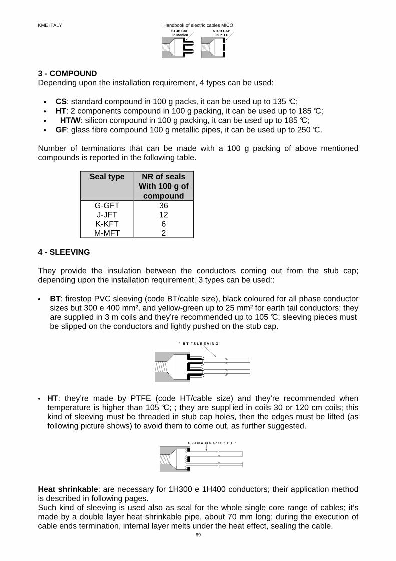
3 - COMPOUND Depending upon the installation requirement, 4 types can be used:
•••• CS: standard compound in 100 g packs, it can be used up to 135 °C; •••• HT: 2 components compound in 100 g packing, it can be used up to 185 °C; •••• HT/W: silicon compound in 100 g packing, it can be used up to 185 °C; •••• GF: glass fibre compound 100 g metallic pipes, it can be used up to 250 °C.
Number of terminations that can be made with a 100 g packing of above mentioned compounds is reported in the following table. Seal type NR of seals
With 100 g of compound
G-GFT J-JFT K-KFT M-MFT
36 12 6 2
4 - SLEEVING They provide the insulation between the conductors coming out from the stub cap; depending upon the installation requirement, 3 types can be used:: •••• BT: firestop PVC sleeving (code BT/cable size), black coloured for all phase conductor
sizes but 300 e 400 mm², and yellow-green up to 25 mm² for earth tail conductors; they are supplied in 3 m coils and they’re recommended up to 105 °C; sleeving pieces must be slipped on the conductors and lightly pushed on the stub cap.
" B T " S L E E V IN G
• HT: they’re made by PTFE (code HT/cable size) and they’re recommended when
temperature is higher than 105 °C; ; they are suppl ied in coils 30 or 120 cm coils; this kind of sleeving must be threaded in stub cap holes, then the edges must be lifted (as following picture shows) to avoid them to come out, as further suggested.
G u a i n a i s o l a n t e " H T "
Heat shrinkable : are necessary for 1H300 e 1H400 conductors; their application method is described in following pages. Such kind of sleeving is used also as seal for the whole single core range of cables; it’s made by a double layer heat shrinkable pipe, about 70 mm long; during the execution of cable ends termination, internal layer melts under the heat effect, sealing the cable.

KME ITALY Handbook of electric cables MICO
70
Following are the correct termination procedures for right execution of termination; the operation sequence is simple, but it requires care by operators.
STARTING CHECK OF INSULATION RESISTANCE Each cable coil is controlled and sealed to keep unchanged in time the insulation resistance; Before starting seal execution, it’s better to cut about 10 cm of cable from both ends; after this, using a Megger with 500 Vcc voltage between conductors and sheath, the insulation resistance value must be controlled to be more than 100 MΩ. Sometimes insulation resistance value could happen to be lower than 100 MΩ (even 5 MΩ); in this case termination execution can start anyway because, like it’s described later, insulation resistance value will reach the required target after 5÷10 minutes.
SUITABLE TOOLS The operation is divided into 3 parts, during which only 2 specific tools are required, beyond the standard ones belonging to common operators tool-set: •••• Stripper It’s used to remove outer copper sheath to let the conductors free for following operations and it’s suitable for Mineral Insulated Cables up to 185 mm² size; it’s composed by 2 opposite “V” shape blocks, one of them is fixed (anyway it can be doubly oriented according to the diameter of the cable) the other can be moved and height adjusted by a screw: the second one is provided with the blade that must cut the copper sheath of the cable.
A d j u s t m e n ts c r e w
B l a d eF r e e " V "
F i x e d " V
•••• Crimping tool for brass pot/stub cap calking In order to joint stub cap and brass pot, you need this tool that, by a height adjustable steel dish with 3 teeth placed at 120° degrees one from the others, allows to make 3 cut on the brass pot edge, avoiding stub cap getting out; 3 different types of crimping tools are available, according to seal size.
G and J/K type (see picture below)
TERMINATION EXECUTION

KME ITALY Handbook of electric cables MICO
71
Screw
Brass pot slot
3 teethsteel dish
J/K crimping tool is provided with reduction cylinder (for brass pot slot) and calking steel dish for J type seals M type: for M seals
Brass pot slot
3 teeth steeldish
Screws
• Using a little saw, cut about 1 cm of cable from the end you want to seal; • Set the stripper on the cable; the blade must rest on the edge of copper sheath and the
upper "V" block must be pressed on the cable by the suitable screw. Pressure must be as strong to joint the tool to the cable but not to avoid the stripper rotation;
• Start rotating the stripper clockwise, pushing it, at the same time, towards the cable
centre; • Do not allow the shaving to collect around the conductors, clasping it to the suitable
hook; • As the stripper removes enough copper sheath, place the pliers to stop stripper
advancing: it will cause the shaving cut, leaving perfectly smooth cable base and free conductors.
CABLE ENDS PREPARATION
KME ITALY Handbook of electric cables MICO
72
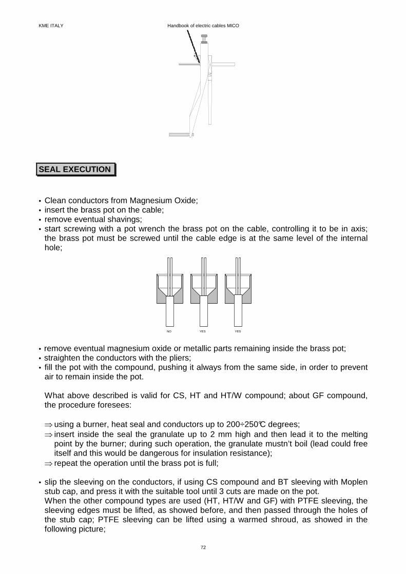
• Clean conductors from Magnesium Oxide; • insert the brass pot on the cable; • remove eventual shavings; • start screwing with a pot wrench the brass pot on the cable, controlling it to be in axis;
the brass pot must be screwed until the cable edge is at the same level of the internal hole;
NO YES YES
• remove eventual magnesium oxide or metallic parts remaining inside the brass pot; • straighten the conductors with the pliers; • fill the pot with the compound, pushing it always from the same side, in order to prevent
air to remain inside the pot. What above described is valid for CS, HT and HT/W compound; about GF compound, the procedure foresees: ⇒ using a burner, heat seal and conductors up to 200÷250°C degrees; ⇒ insert inside the seal the granulate up to 2 mm high and then lead it to the melting
point by the burner; during such operation, the granulate mustn’t boil (lead could free itself and this would be dangerous for insulation resistance);
⇒ repeat the operation until the brass pot is full; • slip the sleeving on the conductors, if using CS compound and BT sleeving with Moplen
stub cap, and press it with the suitable tool until 3 cuts are made on the pot. When the other compound types are used (HT, HT/W and GF) with PTFE sleeving, the sleeving edges must be lifted, as showed before, and then passed through the holes of the stub cap; PTFE sleeving can be lifted using a warmed shroud, as showed in the following picture;
SEAL EXECUTION
KME ITALY Handbook of electric cables MICO
73
Push the sleeving onthe warmed shroud, this way
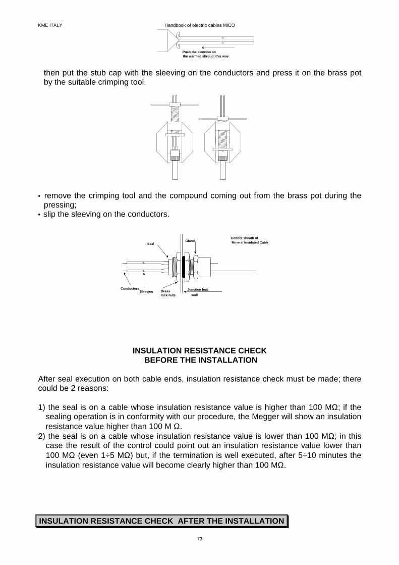
then put the stub cap with the sleeving on the conductors and press it on the brass pot by the suitable crimping tool.
• remove the crimping tool and the compound coming out from the brass pot during the
pressing; • slip the sleeving on the conductors.
Junction box
wall
Copper sheath ofMineral Insulated CableGland
Seal
ConductorsSleeving Brass
lock nuts
INSULATION RESISTANCE CHECK BEFORE THE INSTALLATION
After seal execution on both cable ends, insulation resistance check must be made; there could be 2 reasons: 1) the seal is on a cable whose insulation resistance value is higher than 100 MΩ; if the
sealing operation is in conformity with our procedure, the Megger will show an insulation resistance value higher than 100 M Ω.
2) the seal is on a cable whose insulation resistance value is lower than 100 MΩ; in this case the result of the control could point out an insulation resistance value lower than 100 MΩ (even 1÷5 MΩ) but, if the termination is well executed, after 5÷10 minutes the insulation resistance value will become clearly higher than 100 MΩ.
INSULATION RESISTANCE CHECK AFTER THE INSTALLATION
KME ITALY Handbook of electric cables MICO
74
Rarely happens, during installation final testing, to check low insulation resistance due to a bad execution of a seal; in this case, you can proceed this way: • recognise the defective seal; • remove the seal; • remove compound residual, stripping 2÷3 mm of copper sheath with suitable tool; • restore insulation resistance as suggested before; • start again with seal execution like previously described.
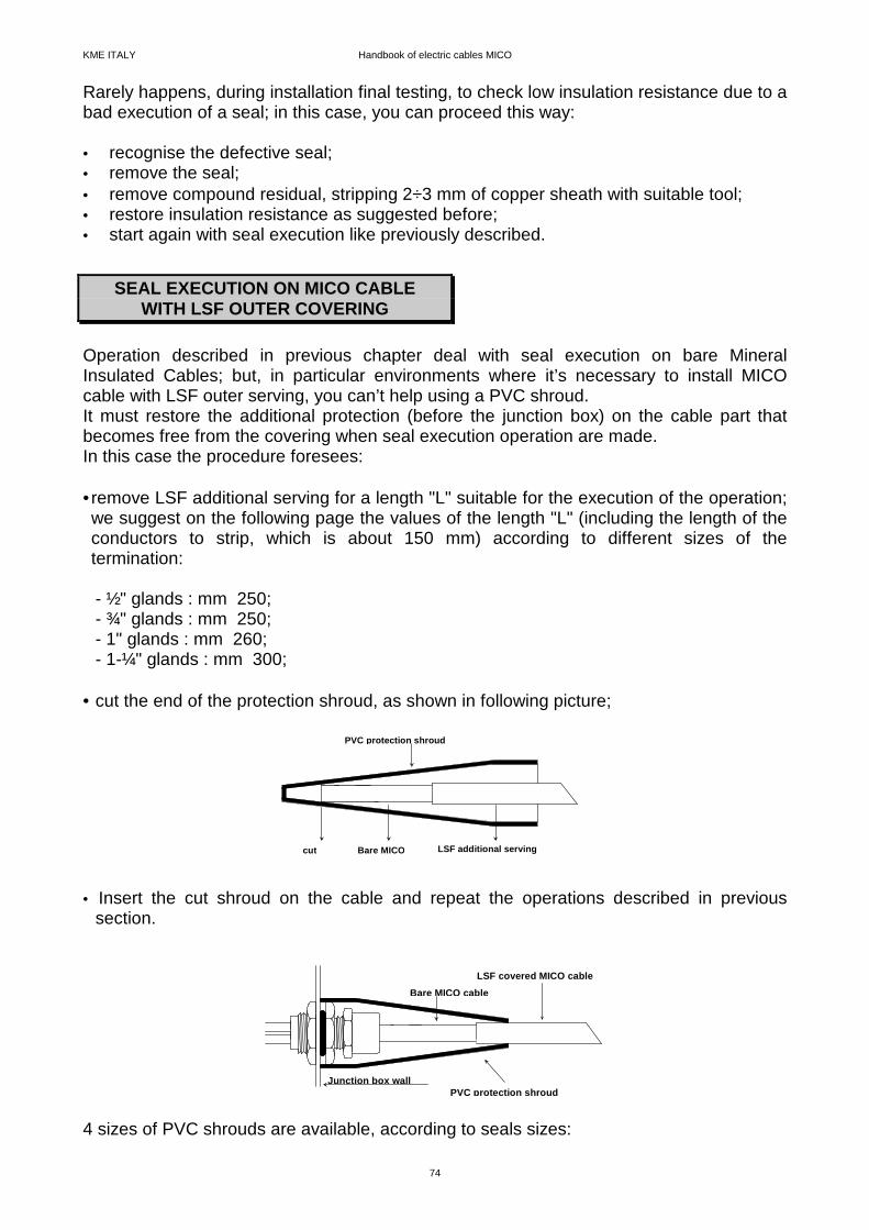
Operation described in previous chapter deal with seal execution on bare Mineral Insulated Cables; but, in particular environments where it’s necessary to install MICO cable with LSF outer serving, you can’t help using a PVC shroud. It must restore the additional protection (before the junction box) on the cable part that becomes free from the covering when seal execution operation are made. In this case the procedure foresees: • remove LSF additional serving for a length "L" suitable for the execution of the operation; we suggest on the following page the values of the length "L" (including the length of the conductors to strip, which is about 150 mm) according to different sizes of the termination: - ½" glands : mm 250; - ¾" glands : mm 250; - 1" glands : mm 260; - 1-¼" glands : mm 300;
• cut the end of the protection shroud, as shown in following picture;
cut
PVC protection shroud
LSF additional servingBare MICO
• Insert the cut shroud on the cable and repeat the operations described in previous
section.
LSF covered MICO cable
PVC protection shroud
Bare MICO cable
Junction box wall
4 sizes of PVC shrouds are available, according to seals sizes:
SEAL EXECUTION ON MICO CABLE WITH LSF OUTER COVERING

KME ITALY Handbook of electric cables MICO
75
- CO1 code: for ½” glands (10 pieces packs); - CO2 code: for ¾” glands (2 pieces packs); - CO3 code: " 1” glands (2 pieces packs); - CO4 code: " 1-¼” glands (2 pieces packs).
As previously stated, such kind of seal is used for 1H300 and 1H400 cables, but can be used also for all the others single core cables; it doesn’t require stripper and crimping tool to be executed, but only a ringer and cutting nippers. Operations to follow are: • cut the copper sheath to easily remove the shaving; it’s important to cut the copper
sheath for half of its thickness. • Remove the copper sheath by helical movement of the cutting nippers; • Check the insulation resistance as previously described procedure; • Clean the stripped conductor with emery cloth; • Remove any eventual impurity from unsealed insulation, to minimise any risk of
decreasing dielectric strength; • Place the heat shrinkable double layer pipe, 70 mm long, on the cable and, with a
burner, make it stick on the cable, taking care of the melting of seal internal layer; in order to be sure about it, it’s better to previously warm the copper sheath and conductor;
• Insert the double layer heat shrinkable sleeving around the conductor and, using a
burner, make it stick on the conductor itself and on the previously placed seal.
EARTH BONDING CLAMPS
When earth tail seals are not used, it’s necessary to use a suitable copper clamp to connect the copper sheath, acting as protection conductor, to the earth bonding of the junction box. In MICO general catalogue, correspondence between cable types and earth bonding clamps codes is shown; each clamps pack is composed by 10 pieces.
THERMO-SHRINKABLE SEAL EXECUTION
ACCESSORIES
KME ITALY Handbook of electric cables MICO
76
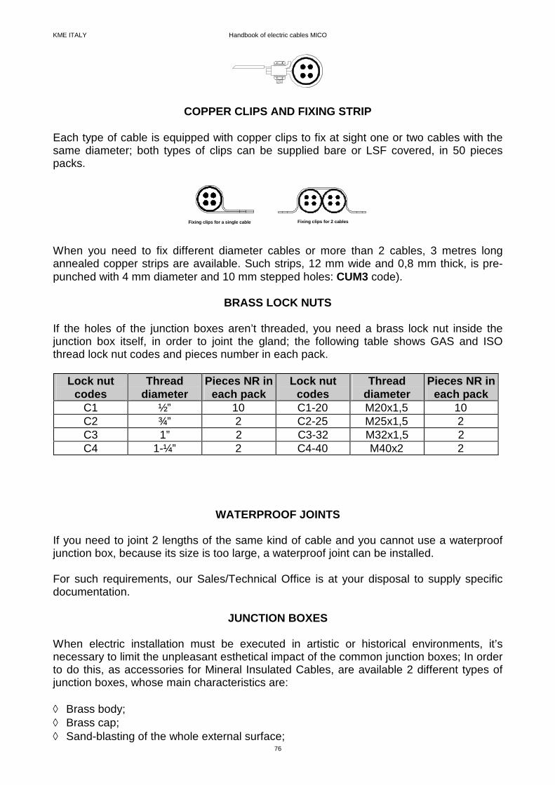
COPPER CLIPS AND FIXING STRIP Each type of cable is equipped with copper clips to fix at sight one or two cables with the same diameter; both types of clips can be supplied bare or LSF covered, in 50 pieces packs.
Fixing clips for a single cable Fixing clips for 2 cables
When you need to fix different diameter cables or more than 2 cables, 3 metres long annealed copper strips are available. Such strips, 12 mm wide and 0,8 mm thick, is pre-punched with 4 mm diameter and 10 mm stepped holes: CUM3 code).
BRASS LOCK NUTS
If the holes of the junction boxes aren’t threaded, you need a brass lock nut inside the junction box itself, in order to joint the gland; the following table shows GAS and ISO thread lock nut codes and pieces number in each pack.
Lock nut codes
Thread diameter
Pieces NR in each pack
Lock nut codes
Thread diameter
Pieces NR i n each pack
C1 ½” 10 C1-20 M20x1,5 10 C2 ¾” 2 C2-25 M25x1,5 2 C3 1” 2 C3-32 M32x1,5 2 C4 1-¼” 2 C4-40 M40x2 2
WATERPROOF JOINTS If you need to joint 2 lengths of the same kind of cable and you cannot use a waterproof junction box, because its size is too large, a waterproof joint can be installed. For such requirements, our Sales/Technical Office is at your disposal to supply specific documentation.
JUNCTION BOXES When electric installation must be executed in artistic or historical environments, it’s necessary to limit the unpleasant esthetical impact of the common junction boxes; In order to do this, as accessories for Mineral Insulated Cables, are available 2 different types of junction boxes, whose main characteristics are: ◊ Brass body; ◊ Brass cap; ◊ Sand-blasting of the whole external surface;
KME ITALY Handbook of electric cables MICO
77
◊ Neoprene membrane; ◊ IP 67 protection degree against dust or fluid penetration, according to CESI GR-
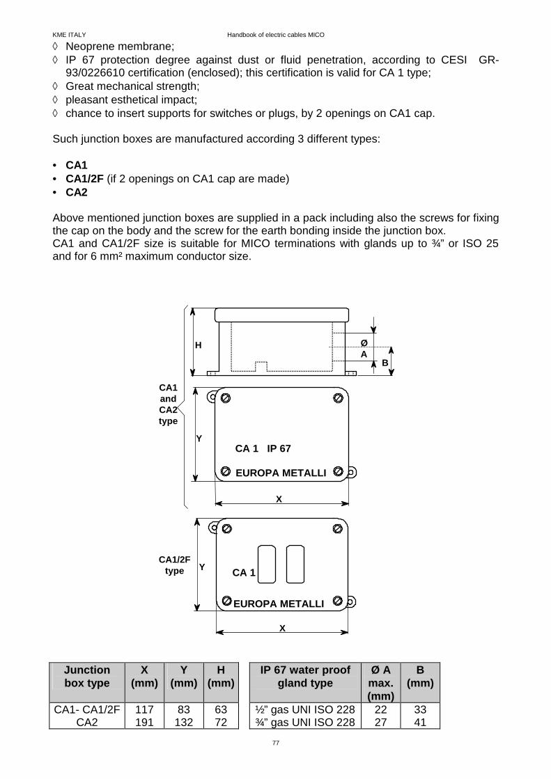
93/0226610 certification (enclosed); this certification is valid for CA 1 type; ◊ Great mechanical strength; ◊ pleasant esthetical impact; ◊ chance to insert supports for switches or plugs, by 2 openings on CA1 cap. Such junction boxes are manufactured according 3 different types: • CA1 • CA1/2F (if 2 openings on CA1 cap are made) • CA2 Above mentioned junction boxes are supplied in a pack including also the screws for fixing the cap on the body and the screw for the earth bonding inside the junction box. CA1 and CA1/2F size is suitable for MICO terminations with glands up to ¾” or ISO 25 and for 6 mm² maximum conductor size.
CA 1 IP 67
ØA
EUROPA METALLI
Y
X
H
B
EUROPA METALLI
CA 1
CA1andCA2type
CA1/2Ftype
X
Y
Junction box type
X (mm)
Y (mm)
H (mm)
IP 67 water proof gland type
Ø A max. (mm)
B (mm)
CA1- CA1/2F CA2
117 191
83 132
63 72
½” gas UNI ISO 228 ¾” gas UNI ISO 228
22 27
33 41