fourier domain mode-locked swept source at 1050 nm based on a tapered amplifier
TRANSCRIPT
Fourier domain mode-locked swept source
at 1050 nm based on a tapered amplifier
Sebastian Marschall,1,*
Thomas Klein,2 Wolfgang Wieser,
2 Benjamin R. Biedermann,
2
Kevin Hsu,3 Kim P. Hansen,
4 Bernd Sumpf,
5 Karl-Heinz Hasler,
5 Götz Erbert,
5 Ole B.
Jensen,1 Christian Pedersen,
1 Robert Huber,
2 and Peter E. Andersen
1
1DTU Fotonik, Department of Photonics Engineering, Technical University of Denmark,
Frederiksborgvej 399, 4000 Roskilde, Denmark 2Lehrstuhl für BioMolekulare Optik, Ludwig-Maximilians-Universität München,
Oettingenstraße 67, 80538 München, Germany 3Micron Optics, Inc., 1852 Century Place NE, Atlanta, GA30345 USA
4NKT Photonics A/S, Blokken 84, DK-3460 Birkerød, Denmark 5Optoelectronics Department, Ferdinand-Braun-Institut, Leibniz-Institut für Höchstfrequenztechnik,
Gustav-Kirchhoff-Straße 4, 12489 Berlin, Germany
Abstract: While swept source optical coherence tomography (OCT) in the
1050 nm range is promising for retinal imaging, there are certain
challenges. Conventional semiconductor gain media have limited output
power, and the performance of high-speed Fourier domain mode-locked
(FDML) lasers suffers from chromatic dispersion in standard optical fiber.
We developed a novel light source with a tapered amplifier as gain medium,
and investigated the FDML performance comparing two fiber delay lines
with different dispersion properties. We introduced an additional gain
element into the resonator, and thereby achieved stable FDML operation,
exploiting the full bandwidth of the tapered amplifier despite high
dispersion. The light source operates at a repetition rate of 116 kHz with an
effective average output power in excess of 30 mW. With a total sweep
range of 70 nm, we achieved an axial resolution of 15 µm in air (~11 µm in
tissue) in OCT measurements. As our work shows, tapered amplifiers are
suitable gain media for swept sources at 1050 nm with increased output
power, while high gain counteracts dispersion effects in an FDML laser.
©2010 Optical Society of America
OCIS codes: (140.3600) Lasers, tunable; (250.5980) Semiconductor optical amplifiers;
(260.2030) Dispersion; (110.4500) Optical coherence tomography; (140.5960) Semiconductor
lasers.
References and links
1. D. Huang, E. A. Swanson, C. P. Lin, J. S. Schuman, W. G. Stinson, W. Chang, M. R. Hee, T. Flotte, K. Gregory,
C. A. Puliafito, and J. G. Fujimoto, “Optical coherence tomography,” Science 254(5035), 1178–1181 (1991).
2. A. F. Fercher, C. K. Hitzenberger, G. Kamp, and S. Y. El-Zaiat, “Measurement of intraocular distances by
backscattering spectral interferometry,” Opt. Commun. 117(1-2), 43–48 (1995).
3. G. Häusler, and M. W. Lindner, “‘coherence radar’ and ‘spectral radar’ – new tools for dermatological
diagnosis,” J. Biomed. Opt. 3(1), 21–31 (1998).
4. M. Choma, M. Sarunic, C. Yang, and J. Izatt, “Sensitivity advantage of swept source and Fourier domain optical
coherence tomography,” Opt. Express 11(18), 2183–2189 (2003).
5. S. R. Chinn, E. A. Swanson, and J. G. Fujimoto, “Optical coherence tomography using a frequency-tunable
optical source,” Opt. Lett. 22(5), 340–342 (1997).
6. B. Golubovic, B. E. Bouma, G. J. Tearney, and J. G. Fujimoto, “Optical frequency-domain reflectometry using
rapid wavelength tuning of a Cr4+:forsterite laser,” Opt. Lett. 22(22), 1704–1706 (1997).
7. R. Leitgeb, C. K. Hitzenberger, and A. F. Fercher, “Performance of fourier domain vs. time domain optical
coherence tomography,” Opt. Express 11(8), 889–894 (2003).
8. W. Wieser, B. R. Biedermann, T. Klein, C. M. Eigenwillig, and R. Huber, “Multi-Megahertz OCT: High quality
3D imaging at 20 million A-scans and 4.5 GVoxels per second,” Opt. Express 18(14), 14685–14704 (2010).
#126798 - $15.00 USD Received 21 Apr 2010; revised 28 Jun 2010; accepted 29 Jun 2010; published 12 Jul 2010(C) 2010 OSA 19 July 2010 / Vol. 18, No. 15 / OPTICS EXPRESS 15820
9. S. H. Yun, G. J. Tearney, J. F. de Boer, and B. E. Bouma, “Motion artifacts in optical coherence tomography
with frequency-domain ranging,” Opt. Express 12(13), 2977–2998 (2004).
10. C. Chong, T. Suzuki, K. Totsuka, A. Morosawa, and T. Sakai, “Large coherence length swept source for axial
length measurement of the eye,” Appl. Opt. 48(10), D144–D150 (2009).
11. S. H. Yun, C. Boudoux, G. J. Tearney, and B. E. Bouma, “High-speed wavelength-swept semiconductor laser
with a polygon-scanner-based wavelength filter,” Opt. Lett. 28(20), 1981–1983 (2003).
12. R. Huber, M. Wojtkowski, K. Taira, J. G. Fujimoto, and K. Hsu, “Amplified, frequency swept lasers for
frequency domain reflectometry and OCT imaging: Design and scaling principles,” Opt. Express 13(9), 3513–
3528 (2005).
13. R. Huber, M. Wojtkowski, and J. G. Fujimoto, “Fourier Domain Mode Locking (FDML): A new laser operating
regime and applications for optical coherence tomography,” Opt. Express 14(8), 3225–3237 (2006).
14. B. Považay, K. Bizheva, B. Hermann, A. Unterhuber, H. Sattmann, A. F. Fercher, W. Drexler, C. Schubert, P. K.
Ahnelt, M. Mei, R. Holzwarth, W. J. Wadsworth, J. C. Knight, and P. S. Russell, “Enhanced visualization of
choroidal vessels using ultrahigh resolution ophthalmic OCT at 1050 nm,” Opt. Express 11(17), 1980–1986
(2003).
15. Y. Wang, J. S. Nelson, Z. Chen, B. J. Reiser, R. S. Chuck, and R. S. Windeler, “Optimal wavelength for
ultrahigh-resolution optical coherence tomography,” Opt. Express 11(12), 1411–1417 (2003).
16. R. Huber, D. C. Adler, and J. G. Fujimoto, “Buffered Fourier domain mode locking: Unidirectional swept laser
sources for optical coherence tomography imaging at 370,000 lines/s,” Opt. Lett. 31(20), 2975–2977 (2006).
17. S. Makita, M. Yamanari, and Y. Yasuno, “High-speed and high-sensitive optical coherence angiography,” Proc.
SPIE 7372, 73721M (2009).
18. M. K. K. Leung, A. Mariampillai, B. A. Standish, K. K. Lee, N. R. Munce, I. A. Vitkin, and V. X. D. Yang,
“High-power wavelength-swept laser in Littman telescope-less polygon filter and dual-amplifier configuration
for multichannel optical coherence tomography,” Opt. Lett. 34(18), 2814–2816 (2009).
19. R. Huber, D. C. Adler, V. J. Srinivasan, and J. G. Fujimoto, “Fourier domain mode locking at 1050 nm for ultra-
high-speed optical coherence tomography of the human retina at 236,000 axial scans per second,” Opt. Lett.
32(14), 2049–2051 (2007).
20. B. R. Biedermann, W. Wieser, C. M. Eigenwillig, T. Klein, and R. Huber, “Dispersion, coherence and noise of
Fourier domain mode locked lasers,” Opt. Express 17(12), 9947–9961 (2009).
21. M. Chi, O. B. Jensen, J. Holm, C. Pedersen, P. E. Andersen, G. Erbert, B. Sumpf, and P. M. Petersen, “Tunable
high-power narrow-linewidth semiconductor laser based on an external-cavity tapered amplifier,” Opt. Express
13(26), 10589–10596 (2005).
22. B. Adhimoolam, M. E. Klein, I. D. Lindsay, P. Groß, C. J. Lee, and K.-J. Boller, “Widely and rapidly tunable
semiconductor master-oscillator fiber amplifier around 1080 nm,” IEEE Photon. Technol. Lett. 18(24), 2683–
2685 (2006).
23. P. Gross, B. Adhimoolam, M. E. Klein, I. D. Lindsay, K. Hsu, and K. Boller, “9-Watt CW Swept-Wavelength
Diode-Oscillator Yb-Fiber-Amplifier System,” in Conference on Lasers and Electro-Optics/Quantum
Electronics and Laser Science Conference and Photonic Applications Systems Technologies, Technical Digest
(CD) (Optical Society of America, 2006), paper CFG5.
24. Y. Wang, W. Liu, J. Fu, and D. Chen, “Quasi-distributed fiber bragg grating sensor system based on a fourier
domain mode locking fiber laser,” Laser Phys. 19(3), 450–454 (2009).
25. S. Marschall, L. Thrane, P. E. Andersen, C. Pedersen, and K. Hsu, “Frequency-swept laser light source at 1050
nm with higher bandwidth due to multiple semiconductor optical amplifiers in series,” Proc. SPIE 7168, 716824
(SPIE, 2009).
26. M. Y. Jeon, J. Zhang, and Z. Chen, “Characterization of Fourier domain mode-locked wavelength swept laser for
optical coherence tomography imaging,” Opt. Express 16(6), 3727–3737 (2008).
27. C. Jirauschek, B. Biedermann, and R. Huber, “A theoretical description of Fourier domain mode locked lasers,”
Opt. Express 17(26), 24013–24019 (2009).
28. M. Haverkamp, G. Kochem, and K. Boucke, “Single mode fiber coupled tapered laser module with frequency
stabilized spectrum,” Proc. SPIE 6876, 68761D (2008).
29. W.-Y. Oh, S.-H. Yun, G. J. Tearney, and B. E. Bouma, “115 kHz tuning repetition rate ultrahigh-speed
wavelength-swept semiconductor laser,” Opt. Lett. 30(23), 3159–3161 (2005).
1. Introduction
Optical coherence tomography (OCT) has become an important technique for biomedical
imaging [1]. OCT can be divided into two domains, namely time domain-OCT and frequency
domain-OCT. During recent years, frequency domain-OCT [2, 3] has developed rapidly,
because it allows for significantly increased imaging speed and higher sensitivity [4]. In
frequency domain-OCT, the light back-scattered from the sample interferes with light from a
reference path, creating an interference pattern in the optical frequency domain. To retrieve
the relevant information, one must sample the spectrum of the light exiting the interferometer,
which can be done in one of the following two ways: In spectral domain-OCT, a spectrometer
#126798 - $15.00 USD Received 21 Apr 2010; revised 28 Jun 2010; accepted 29 Jun 2010; published 12 Jul 2010(C) 2010 OSA 19 July 2010 / Vol. 18, No. 15 / OPTICS EXPRESS 15821
is used in conjunction with a broadband light source. Alternatively, one can use a simple
photo detector and a narrowband light source that sweeps its wavelength rapidly over a broad
range [5, 6]. The latter technique, called swept source-OCT, is well suited for high speed
imaging at wavelengths above 1000 nm, because it needs only readily available photo diodes
for the detection. Spectral domain-OCT in this wavelength range requires usually InGaAs-
based line cameras. These are expensive and have low pixel numbers, leading to a limited
OCT ranging depth [7]. The simpler detection method of swept source-OCT allows also for
dual balanced detection and comparably easy implementation of multi-spot imaging setups
[8]. Furthermore, swept source-OCT is less prone to fringe washout effects caused by sample
motion [9], and it can provide very high ranging depths [10].
One common implementation of a swept source is a laser based on a fiber ring resonator
comprising a semiconductor optical amplifier (SOA) as gain medium and a tunable filter for
wavelength selection [11, 12]. In contrast to a free-space resonator, a fiber-based setup
enables implementing the Fourier domain mode-locking (FDML) technique in order to
overcome the limitation in sweep velocity given by the build-up time of laser light in the
cavity [13]. The concept of FDML is to synchronize the sweep rate of the tunable filter, fsw,
with the cavity round trip frequency, frt, in order to sustain uninterrupted lasing. To fulfill the
frequency matching condition fsw = frt = c / (n · lres), where c is the speed of light, lres the
length of the resonator, and n its effective index of refraction, frt. must be in the range of
sweep rates supported by the filter. Typically, one decreases frt to some tens or hundreds of
kilohertz with a delay line of several kilometers length.
Light in the wavelength region around 1050 nm is well suited for retinal imaging. It
allows for deeper penetration into the choroid than visible light and does not suffer from
water absorption as severely as light with a wavelength above 1100 nm [14]. Furthermore, the
dispersion in water, the main constituent of the vitreous, is minimal in the 1050 nm region,
which is beneficial for maintaining a high depth resolution [15]. However, there are some
challenges for the implementation of swept sources. SOAs for this wavelength are not as
well-developed as those for the telecom bands (1300 nm or 1550 nm) and have significantly
lower saturation power. Therefore, one often needs to post-amplify the output light of the
swept source with a second SOA. Even though the sample power has to be limited for
biological samples, e. g. to a few milliwatts for retinal imaging at 1050 nm, additional power
can be required in order to compensate for losses in the imaging setup or for other purposes.
For instance, buffering allows to “rectify” the sweep direction [16] or to achieve ultra-high A-
scan rates [8] by splitting the laser output during one sweep into several “copies” and
delaying them relative to each other, albeit at a power penalty of at least 6 dB. There are also
OCT applications with multiple beams scanning the sample in parallel [17, 18]. Provided
sufficient beam spacing, each beam can illuminate its target spot with the full allowed
intensity. Another problem in the 1050 nm range is chromatic dispersion in standard single-
mode fiber. In an FDML swept source, dispersion in the delay line limits the achievable
tuning bandwidth, because frequency synchronization for all wavelengths simultaneously is
impossible [19]. Under these conditions, extended photon cavity lifetime is only possible in a
narrow wavelength band, while other spectral components exhibit reduced transmission
through the tunable filter [20].
We propose a novel FDML light source configuration for the 1050 nm range that allows
for high output power and broad bandwidth. We introduce a tapered amplifier as an
alternative gain medium. This semiconductor gain element features a far higher saturation
power than conventional SOAs due to its particular architecture. Previously, Chi et al. used a
tapered amplifier in a high-power laser, tunable around 800 nm [21]. Adhimoolam and Groß
et al. demonstrated wavelength-swept lasers at 1080 nm with sweep rates from 0.1 to 1 kHz
based on a tapered amplifier in a free-space ring resonator [22, 23]. Here, we present the
integration of a tapered amplifier into a fiber-based swept source and prove its feasibility for
high-speed FDML operation.
#126798 - $15.00 USD Received 21 Apr 2010; revised 28 Jun 2010; accepted 29 Jun 2010; published 12 Jul 2010(C) 2010 OSA 19 July 2010 / Vol. 18, No. 15 / OPTICS EXPRESS 15822
Furthermore, we investigate the influence of dispersion by comparing the FDML
performance with two different fibers as delay line: a standard single-mode fiber and a low-
dispersion photonic crystal fiber (PCF). With the PCF, the effects of dispersion are
significantly reduced, but its high insertion loss leads to lower overall performance in
comparison to the standard fiber.
In both configurations, we achieve high FDML performance with an additional
conventional SOA in the resonator. The extra gain provided by the SOA does not only
compensate for intrinsic losses, it also helps to overcome the bandwidth-limiting effects of
dispersion in the standard fiber. Thus, we can exploit the full tuning bandwidth of the tapered
amplifier even in conjunction with the dispersive delay line. In contrast to other
configurations with equal gain media in series [18, 24, 25], we use two different amplifiers
with complementary characteristics. The conventional SOA provides a large small-signal
gain, while the tapered amplifier features high saturation power. This combination allows for
stable FDML operation with high output power and broad bandwidth at the same time.
This paper presents the developed light source setup (Sec. 2). It discusses the results of the
characterization, along with observations made during the measurements, and shows OCT
images acquired with the light source (Sec. 3). After summarizing the results (Sec. 4), it
provides an outlook on the possibilities for further development (Sec. 5).
2. Setup
This section provides an overview over the light source setup (Sec. 2.1) and describes in
detail the key components and their role within the system, namely the tapered amplifier (Sec.
2.2), the delay line (Sec. 2.3), and the auxiliary SOA (Sec. 2.4). The latter section also
includes a discussion on the relation of dispersion and gain in FDML lasers.
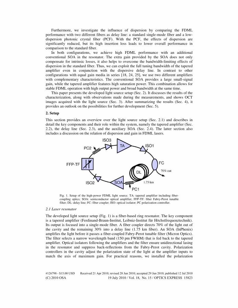
Fig. 1. Setup of the high-power FDML light source. TA: tapered amplifier including fiber-
coupling optics; SOA: semiconductor optical amplifier, FFP-TF: fiber Fabry-Perot tunable
filter; DL: delay line; FC: fiber coupler; ISO: optical isolator; PC polarization controller.
2.1 Laser resonator
The developed light source setup (Fig. 1) is a fiber-based ring resonator. The key component
is a tapered amplifier (Ferdinand-Braun-Institut, Leibniz-Institut für Höchstfrequenztechnik).
Its output is focused into a single-mode fiber. A fiber coupler directs 70% of the light out of
the cavity and the remaining 30% into a delay line (1.75 km fiber). An SOA (InPhenix)
amplifies the light before it passes a fiber-coupled Fabry-Perot tunable filter (Micron Optics).
The filter selects a narrow wavelength band (150 pm FWHM) that is fed back to the tapered
amplifier. Optical isolators following the amplifiers and the filter ensure unidirectional lasing
in the resonator and suppress back-reflections from the Fabry-Perot cavity. Polarization
controllers in the cavity adjust the polarization state of the light at the amplifier inputs to
match the axis of maximum gain. For practical reasons, we installed the polarization
#126798 - $15.00 USD Received 21 Apr 2010; revised 28 Jun 2010; accepted 29 Jun 2010; published 12 Jul 2010(C) 2010 OSA 19 July 2010 / Vol. 18, No. 15 / OPTICS EXPRESS 15823
controller for the tapered amplifier (PC2) on the input fiber of the isolator in front of it
(ISO3).
2.2 Tapered amplifier
Tapered amplifiers are suitable gain media for fiber-based lasers with high output power.
These devices are a type of SOA with a special waveguide architecture. On the input side, the
waveguide has a straight narrow section that supports only the fundamental transverse mode
of the light field. It is followed by the tapered section, where the waveguide slowly broadens,
so that the mode field expands while maintaining its original single-mode profile. In contrast
to conventional SOAs with a single-mode waveguide, tapered amplifiers allow for high drive
currents (several amperes) and therefore provide high saturated output power (up to several
watts), but still emit a beam of high quality, suitable for single-mode fiber coupling. We
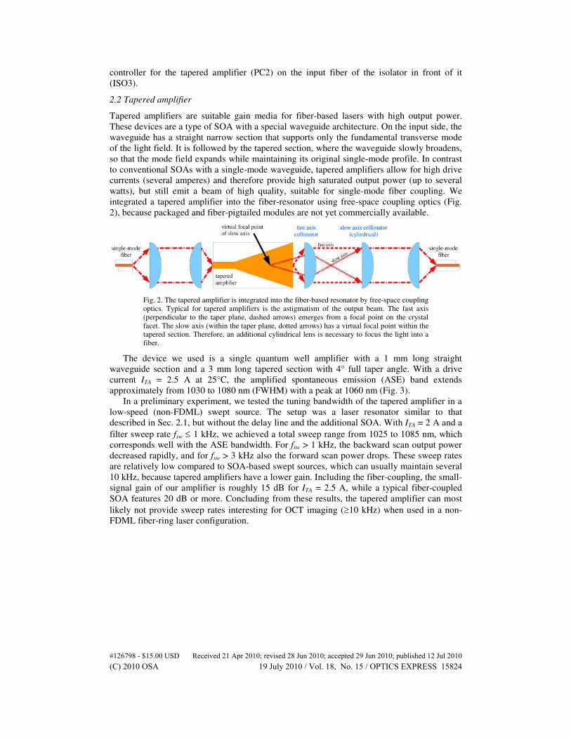
integrated a tapered amplifier into the fiber-resonator using free-space coupling optics (Fig.
2), because packaged and fiber-pigtailed modules are not yet commercially available.
Fig. 2. The tapered amplifier is integrated into the fiber-based resonator by free-space coupling
optics. Typical for tapered amplifiers is the astigmatism of the output beam. The fast axis
(perpendicular to the taper plane, dashed arrows) emerges from a focal point on the crystal
facet. The slow axis (within the taper plane, dotted arrows) has a virtual focal point within the
tapered section. Therefore, an additional cylindrical lens is necessary to focus the light into a
fiber.
The device we used is a single quantum well amplifier with a 1 mm long straight
waveguide section and a 3 mm long tapered section with 4° full taper angle. With a drive
current ITA = 2.5 A at 25°C, the amplified spontaneous emission (ASE) band extends
approximately from 1030 to 1080 nm (FWHM) with a peak at 1060 nm (Fig. 3).
In a preliminary experiment, we tested the tuning bandwidth of the tapered amplifier in a
low-speed (non-FDML) swept source. The setup was a laser resonator similar to that
described in Sec. 2.1, but without the delay line and the additional SOA. With ITA = 2 A and a
filter sweep rate fsw ≤ 1 kHz, we achieved a total sweep range from 1025 to 1085 nm, which
corresponds well with the ASE bandwidth. For fsw > 1 kHz, the backward scan output power
decreased rapidly, and for fsw > 3 kHz also the forward scan power drops. These sweep rates
are relatively low compared to SOA-based swept sources, which can usually maintain several
10 kHz, because tapered amplifiers have a lower gain. Including the fiber-coupling, the small-
signal gain of our amplifier is roughly 15 dB for ITA = 2.5 A, while a typical fiber-coupled
SOA features 20 dB or more. Concluding from these results, the tapered amplifier can most
likely not provide sweep rates interesting for OCT imaging (≥10 kHz) when used in a non-
FDML fiber-ring laser configuration.
#126798 - $15.00 USD Received 21 Apr 2010; revised 28 Jun 2010; accepted 29 Jun 2010; published 12 Jul 2010(C) 2010 OSA 19 July 2010 / Vol. 18, No. 15 / OPTICS EXPRESS 15824

Fig. 3. Spontaneous emission spectrum of the tapered amplifier for 2.5 A drive current.
2.3 Delay line
The delay line decreases the resonator round trip frequency, allowing the sweep frequency of
the tunable filter to be synchronized with it. The chosen length of 1.75 km results in a
resonator round trip frequency of roughly 116 kHz, which is close to a mechanical resonance
of the filter. We can thus achieve a large sweep amplitude with moderate drive currents.
We tested the light source using two different delay lines, one consisting of standard
single-mode fiber and one made of a special low-dispersion photonic crystal fiber (PCF). The
single-mode fiber (Corning HI-1060) has a low insertion loss, around 2 dB, but introduces a
significant amount of chromatic dispersion. The longest and the shortest round trip time in the
range of interest (1030 nm to 1100 nm) differ by approximately 4.5 ns. The PCF (NKT
Photonics SC-5.0-1040) is tailored to have zero dispersion at 1040 nm. We do not have
precise measurement data of the dispersion, but we estimated the maximum difference of
round trip times to about 0.7 to 1.4 ns. The insertion loss of the PCF is comparably high for
this application, around 10 dB. It originates partly from inherent attenuation (~3.8 dB/km
according to the manufacturer test data) and partly from several splices between the PCF, the
standard fiber that forms the rest of the resonator, and a mode-field adapting intermediate
fiber.
2.4 Auxiliary SOA
The SOA is essential for high FDML performance. It increases the gain per round trip in the
resonator substantially and compensates for the high insertion loss when the PCF delay line is
used. In case of low loss and high dispersion, as with the HI-1060 delay line, the high gain
counteracts the effects of dispersion, which would otherwise impair the FDML operation.
Several authors have studied how the dispersion-caused round trip mismatch affects an
FDML light source. Huber et al. calculated a minimum line width for the tunable filter that
allows light with a given mismatch to complete at least one round trip [19]. Biedermann et al.
stated that the mismatch leads to reduced transmission through the tunable filter and
estimated the maximum possible photon cavity lifetime in order to study the influence on the
instantaneous laser line width [20].
Here, we investigate the effect of dispersion on the available FDML tuning bandwidth.
Lasing is possible at wavelengths where the small-signal gain exceeds the total loss in the
resonator. In addition to the intrinsic insertion loss of the components, dispersion leads under
FDML operation to further wavelength-dependent loss in the tunable filter. This can be
understood with the following consideration. Let the transmission window of the filter at time
t1 be centered at the wavelength λ1. The narrow band of transmitted light travels then once
through the resonator within the round trip time τrt(λ1). If the filter sweep period τsw matches
τrt(λ1), the light arrives at the filter when the transmission window is again centered at λ1, and
passes with minimal loss. If the resonator exhibits chromatic dispersion, τrt does not equal τsw
for most wavelengths. In this case, the transmission window and the band of arriving light are
spectrally mismatched by λmis(λ1) = vsw(λ1) · [τrt(λ1) − τsw], where vsw is the sweep velocity, i. e.
the rate at which the filter wavelength changes (Fig. 4). The larger λmis is, the smaller is the
#126798 - $15.00 USD Received 21 Apr 2010; revised 28 Jun 2010; accepted 29 Jun 2010; published 12 Jul 2010(C) 2010 OSA 19 July 2010 / Vol. 18, No. 15 / OPTICS EXPRESS 15825
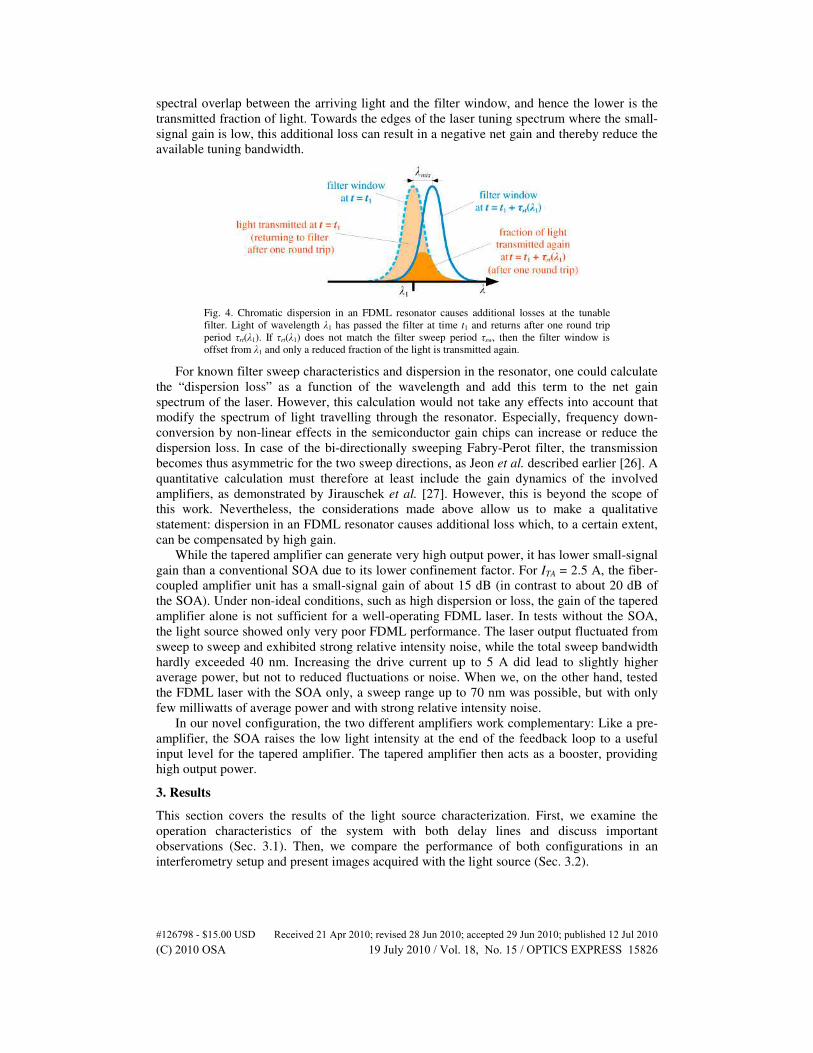
spectral overlap between the arriving light and the filter window, and hence the lower is the
transmitted fraction of light. Towards the edges of the laser tuning spectrum where the small-
signal gain is low, this additional loss can result in a negative net gain and thereby reduce the
available tuning bandwidth.
Fig. 4. Chromatic dispersion in an FDML resonator causes additional losses at the tunable
filter. Light of wavelength λ1 has passed the filter at time t1 and returns after one round trip
period τrt(λ1). If τrt(λ1) does not match the filter sweep period τsw, then the filter window is
offset from λ1 and only a reduced fraction of the light is transmitted again.
For known filter sweep characteristics and dispersion in the resonator, one could calculate
the “dispersion loss” as a function of the wavelength and add this term to the net gain
spectrum of the laser. However, this calculation would not take any effects into account that
modify the spectrum of light travelling through the resonator. Especially, frequency down-
conversion by non-linear effects in the semiconductor gain chips can increase or reduce the
dispersion loss. In case of the bi-directionally sweeping Fabry-Perot filter, the transmission
becomes thus asymmetric for the two sweep directions, as Jeon et al. described earlier [26]. A
quantitative calculation must therefore at least include the gain dynamics of the involved
amplifiers, as demonstrated by Jirauschek et al. [27]. However, this is beyond the scope of
this work. Nevertheless, the considerations made above allow us to make a qualitative
statement: dispersion in an FDML resonator causes additional loss which, to a certain extent,
can be compensated by high gain.
While the tapered amplifier can generate very high output power, it has lower small-signal
gain than a conventional SOA due to its lower confinement factor. For ITA = 2.5 A, the fiber-
coupled amplifier unit has a small-signal gain of about 15 dB (in contrast to about 20 dB of
the SOA). Under non-ideal conditions, such as high dispersion or loss, the gain of the tapered
amplifier alone is not sufficient for a well-operating FDML laser. In tests without the SOA,
the light source showed only very poor FDML performance. The laser output fluctuated from
sweep to sweep and exhibited strong relative intensity noise, while the total sweep bandwidth
hardly exceeded 40 nm. Increasing the drive current up to 5 A did lead to slightly higher
average power, but not to reduced fluctuations or noise. When we, on the other hand, tested
the FDML laser with the SOA only, a sweep range up to 70 nm was possible, but with only
few milliwatts of average power and with strong relative intensity noise.
In our novel configuration, the two different amplifiers work complementary: Like a pre-
amplifier, the SOA raises the low light intensity at the end of the feedback loop to a useful
input level for the tapered amplifier. The tapered amplifier then acts as a booster, providing
high output power.
3. Results
This section covers the results of the light source characterization. First, we examine the
operation characteristics of the system with both delay lines and discuss important
observations (Sec. 3.1). Then, we compare the performance of both configurations in an
interferometry setup and present images acquired with the light source (Sec. 3.2).
#126798 - $15.00 USD Received 21 Apr 2010; revised 28 Jun 2010; accepted 29 Jun 2010; published 12 Jul 2010(C) 2010 OSA 19 July 2010 / Vol. 18, No. 15 / OPTICS EXPRESS 15826
3.1 Light source characteristics
With the HI-1060 delay line, the light source allows for FDML operation with maximal
tuning bandwidth for the sweep frequency fsw ranging from 116.78 to 116.86 kHz. This is
different from FDML systems at 1300 nm, where dispersion in the delay line is very low and
the resonator round trip frequency frt is nearly constant within the entire sweep spectrum. At
1050 nm, frt varies significantly over the sweep range, so that the FDML operating frequency
is no longer clearly defined.
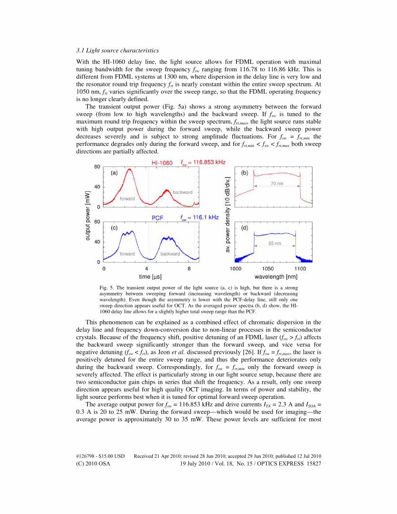
The transient output power (Fig. 5a) shows a strong asymmetry between the forward
sweep (from low to high wavelengths) and the backward sweep. If fsw is tuned to the
maximum round trip frequency within the sweep spectrum, frt,max, the light source runs stable
with high output power during the forward sweep, while the backward sweep power
decreases severely and is subject to strong amplitude fluctuations. For fsw = frt,min the
performance degrades only during the forward sweep, and for frt,min < fsw < frt,max both sweep
directions are partially affected.
Fig. 5. The transient output power of the light source (a, c) is high, but there is a strong
asymmetry between sweeping forward (increasing wavelength) or backward (decreasing
wavelength). Even though the asymmetry is lower with the PCF-delay line, still only one
sweep direction appears useful for OCT. As the averaged power spectra (b, d) show, the HI-
1060 delay line allows for a slightly higher total sweep range than the PCF.
This phenomenon can be explained as a combined effect of chromatic dispersion in the
delay line and frequency down-conversion due to non-linear processes in the semiconductor
crystals. Because of the frequency shift, positive detuning of an FDML laser (fsw > frt) affects
the backward sweep significantly stronger than the forward sweep, and vice versa for
negative detuning (fsw < frt), as Jeon et al. discussed previously [26]. If fsw = frt,max, the laser is
positively detuned for the entire sweep range, and thus the performance deteriorates only
during the backward sweep. Correspondingly, for fsw = frt,min only the forward sweep is
severely affected. The effect is particularly strong in our light source setup, because there are
two semiconductor gain chips in series that shift the frequency. As a result, only one sweep
direction appears useful for high quality OCT imaging. In terms of power and stability, the
light source performs best when it is tuned for optimal forward sweep operation.
The average output power for fsw = 116.853 kHz and drive currents ITA = 2.3 A and ISOA =
0.3 A is 20 to 25 mW. During the forward sweep—which would be used for imaging—the
average power is approximately 30 to 35 mW. These power levels are sufficient for most
#126798 - $15.00 USD Received 21 Apr 2010; revised 28 Jun 2010; accepted 29 Jun 2010; published 12 Jul 2010(C) 2010 OSA 19 July 2010 / Vol. 18, No. 15 / OPTICS EXPRESS 15827
ophthalmic applications. Even if one buffers the forward sweep in order to double the OCT
A-scan rate, one has two outputs with at least 7 mW each to work with.
However, these output power levels are actually lower than expected. In a simple free-
space cw-resonator, our tapered amplifier emitted several hundred milliwatts with 1 to 2 A
drive current, and in general such devices can generate several watts of laser light [21, 28].
Apparently, the feedback in the current fiber-optic configuration is not sufficient to saturate
the gain of the tapered amplifier. The SOA, on the other hand, works in the saturation regime
and limits thereby the feedback to the tapered amplifier. In conjunction with losses caused by
the fiber-coupling optics and the other components, this leads to the comparably low output.
One could increase the power by optimizing the fiber-coupling, by using an SOA with higher
saturation power, or by driving the tapered amplifier with a higher current.
The total sweep range is 70 nm (Fig. 5b), and the 3 dB-bandwidth after linearization in the
optical frequency domain is 11.5 THz (~42 nm). This corresponds well with the tuning range
of the tapered amplifier during the preliminary test (Sec. 2.2). Obviously, this FDML laser
configuration exploits the gain bandwidth of the tapered amplifier very well, even though the
resonator is subject to high chromatic dispersion. An adequate modulation of ISOA during the
sweep cycle can possibly increase the bandwidth even further by shaping the output spectrum
flatter and broader.
With the PCF delay line, the sweep frequency range for FDML operation is narrower,
116.085 to 116.1 kHz, and the asymmetry in the transient output power (Fig. 5c) is
significantly lower, both due to lower dispersion. Still, one sweep direction is subject to
strong power fluctuations and does not appear useful for OCT. It is also difficult to adjust the
polarization in order to achieve a smooth spectrum without dips. For fsw = 116.1 kHz and the
same drive currents as above, the forward sweep is stable and has an average power around
30 mW. The total sweep range is 65 nm (Fig. 5d) and the 3 dB-bandwidth roughly 42 nm.
The characteristics of both configurations are remarkably similar because of common
limiting factors. The saturation power of the SOA limits the output power of the light source,
whereas the gain bandwidth of the tapered amplifier limits the sweep bandwidth. Regarding
the effects of dispersion, the PCF-configuration is clearly closer to the ideal case, where both
sweep directions exhibit symmetric output power. But due to the very high insertion loss, it
does not improve the overall performance in this light source embodiment. However, the PCF
could be of advantage in a light source with higher gain bandwidth, where dispersion has a
stronger impact, or with higher sweep frequency, where the delay line is shorter and hence the
insertion loss is lower.
3.2 Interferometry and imaging
In order to test the performance of the light source for OCT imaging, we generated point
spread functions (PSF) in a Mach-Zehnder interferometer (MZI) with variable path length
difference, using the output during the forward sweep (Fig. 6). For both delay lines, the PSFs
have a width (3 dB) of 15 µm, which is somewhat higher than the theoretical ideal value of 12
µm, assuming a Gaussian spectrum with 42 nm FWHM. Still, the resulting axial resolution of
11 µm in biologic tissue is adequate for OCT imaging.
#126798 - $15.00 USD Received 21 Apr 2010; revised 28 Jun 2010; accepted 29 Jun 2010; published 12 Jul 2010(C) 2010 OSA 19 July 2010 / Vol. 18, No. 15 / OPTICS EXPRESS 15828
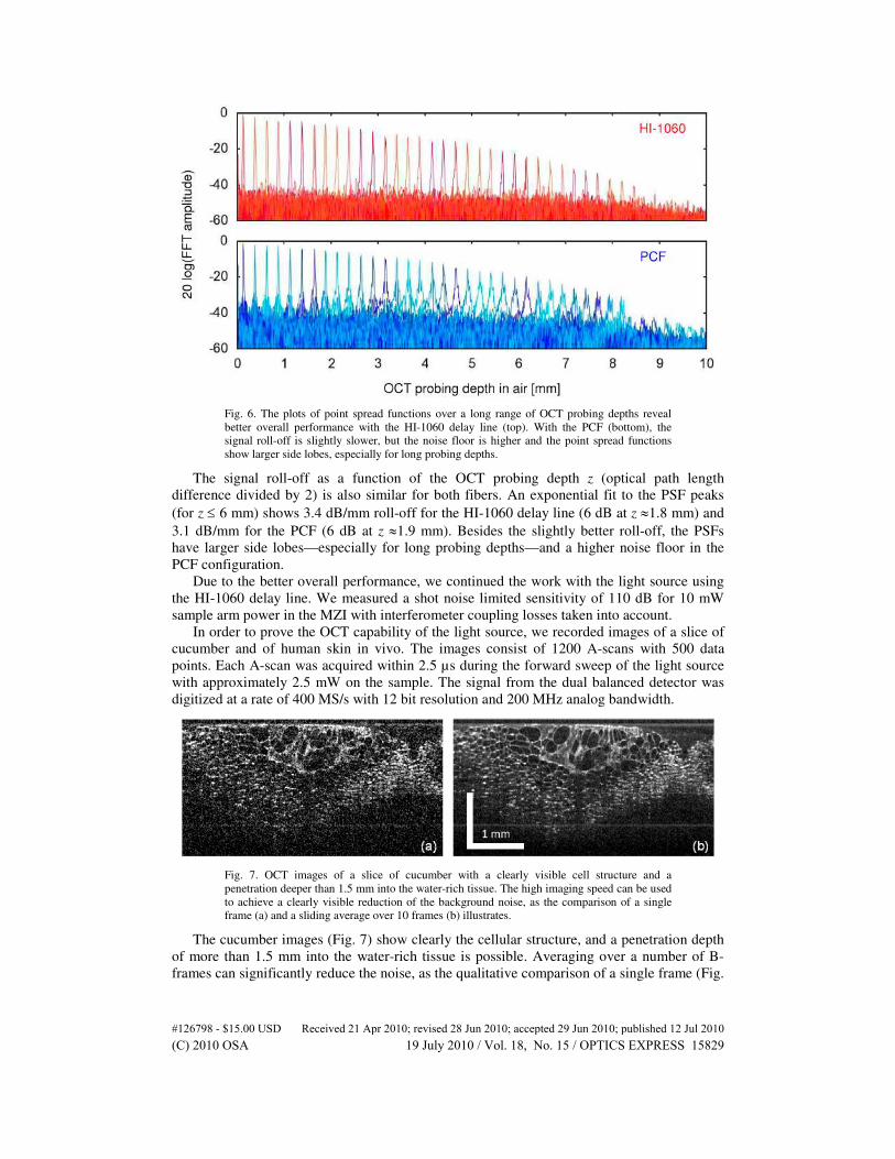
Fig. 6. The plots of point spread functions over a long range of OCT probing depths reveal
better overall performance with the HI-1060 delay line (top). With the PCF (bottom), the
signal roll-off is slightly slower, but the noise floor is higher and the point spread functions
show larger side lobes, especially for long probing depths.
The signal roll-off as a function of the OCT probing depth z (optical path length
difference divided by 2) is also similar for both fibers. An exponential fit to the PSF peaks
(for z ≤ 6 mm) shows 3.4 dB/mm roll-off for the HI-1060 delay line (6 dB at z ≈1.8 mm) and
3.1 dB/mm for the PCF (6 dB at z ≈1.9 mm). Besides the slightly better roll-off, the PSFs
have larger side lobes—especially for long probing depths—and a higher noise floor in the
PCF configuration.
Due to the better overall performance, we continued the work with the light source using
the HI-1060 delay line. We measured a shot noise limited sensitivity of 110 dB for 10 mW
sample arm power in the MZI with interferometer coupling losses taken into account.
In order to prove the OCT capability of the light source, we recorded images of a slice of
cucumber and of human skin in vivo. The images consist of 1200 A-scans with 500 data
points. Each A-scan was acquired within 2.5 µs during the forward sweep of the light source
with approximately 2.5 mW on the sample. The signal from the dual balanced detector was
digitized at a rate of 400 MS/s with 12 bit resolution and 200 MHz analog bandwidth.
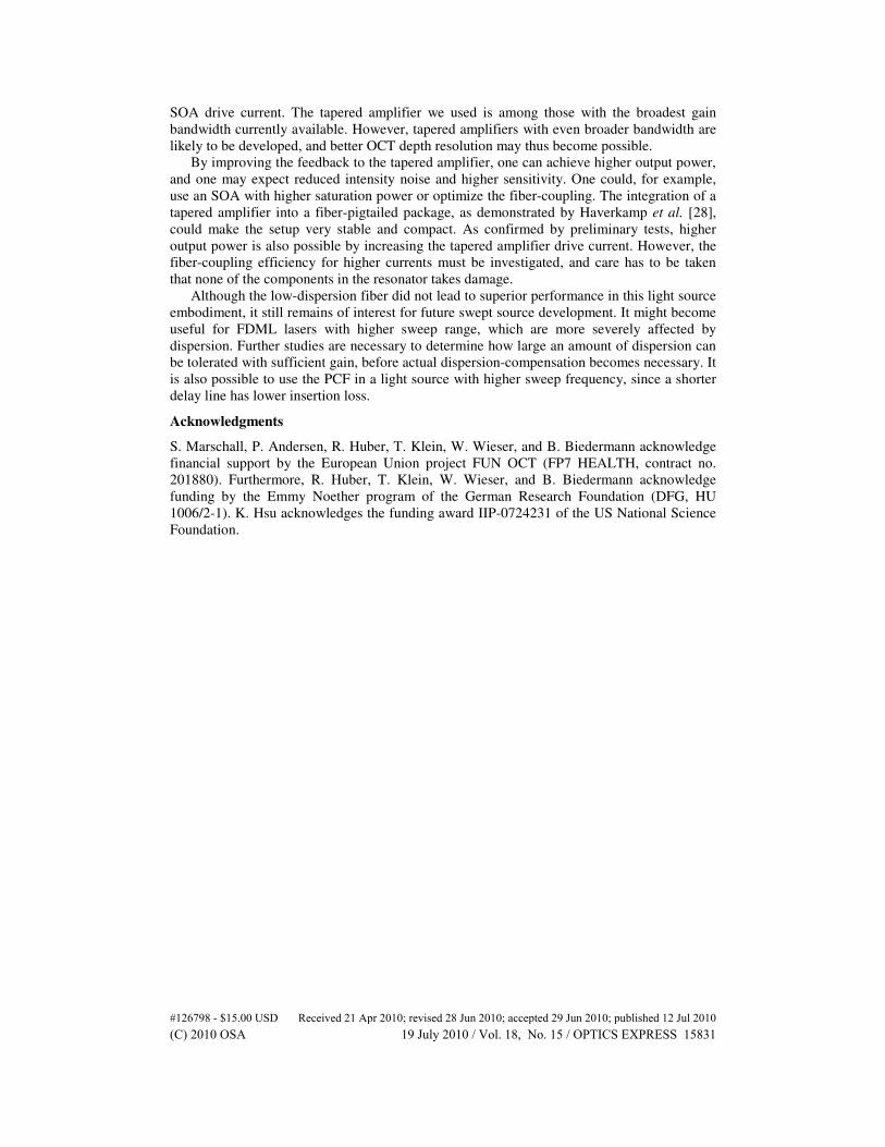
Fig. 7. OCT images of a slice of cucumber with a clearly visible cell structure and a
penetration deeper than 1.5 mm into the water-rich tissue. The high imaging speed can be used
to achieve a clearly visible reduction of the background noise, as the comparison of a single
frame (a) and a sliding average over 10 frames (b) illustrates.
The cucumber images (Fig. 7) show clearly the cellular structure, and a penetration depth
of more than 1.5 mm into the water-rich tissue is possible. Averaging over a number of B-
frames can significantly reduce the noise, as the qualitative comparison of a single frame (Fig.
#126798 - $15.00 USD Received 21 Apr 2010; revised 28 Jun 2010; accepted 29 Jun 2010; published 12 Jul 2010(C) 2010 OSA 19 July 2010 / Vol. 18, No. 15 / OPTICS EXPRESS 15829

7a) and a sliding average over 10 B-scans (Fig. 7b) reveals. This shows the potential of
speckle and background noise reduction while imaging at high speed. For the scale bar we
assumed a refractive index of 1.33 in axial direction. The skin images were recorded at the
finger tip (Fig. 8a) and the nail fold (Fig. 8b). A sliding average over 3 frames resulted in a
good reduction of background noise. We rescaled the images assuming a refractive index of
1.4. Clearly visible features are the border between the thick stratum corneum at the finger tip
and the lower parts of the epidermis, as well as the cross-section through the nail-plate and
the epidermis structure in the cuticle region.
Fig. 8. OCT images of human skin in vivo. (a) Skin at the finger tip with a thick stratum
corneum (Co) and a clearly visible border to the stratum spinosum (Sp). (b) Nail fold with a
cross-section through the nail-plate (Np) and the epidermis structure in the cuticle region. The
images are averaged over 3 frames.
4. Conclusion
We constructed an FDML swept source with a tapered amplifier as gain medium, sweeping
bi-directionally at a repetition rate of 116 kHz with an average output power of more than 30
mW during the forward sweep. With a total sweep bandwidth of 70 nm, we achieved an axial
resolution of 15 µm in air (11 µm in tissue). As the measured values for sensitivity (110 dB)
and signal roll-off (3.4 dB/mm) indicate, the light source is suitable for OCT imaging, which
we confirmed by acquiring a number of images.
We compared the light source performance using a standard single-mode fiber and a low-
dispersion photonic crystal fiber as delay line. Although the effects of dispersion were clearly
reduced with the PCF delay line, it did not improve the performance because of its high
insertion loss. With the high gain of an auxiliary SOA, on the other hand, we exploited the
full gain bandwidth of the tapered amplifier even with the dispersive standard fiber delay line.
These results bring two important insights for future swept source development. (1)
Tapered amplifiers are suitable gain media, when high output power is required. (2) High gain
counteracts the effects of dispersion in an FDML system and can help to maintain a high
sweep bandwidth.
5. Future light source development
There are a number of possibilities both to improve our current swept source further and to
continue research based on our results.
Due to the strong asymmetry of the output power between the two sweep directions, we
used so far only the forward sweep for imaging. In other words, we operated with a 50% duty
cycle. However, it would be straight forward to discard the backward sweep and to buffer the
output in order to increase the A-scan to 233 kHz. Both outputs of the buffering stage would
have sufficient power for OCT imaging (>7mW) without post-amplification.
One could also achieve a 100% duty cycle with full output power by using a tunable filter
sweeping uni-directionally from low to high wavelengths. However, the fastest reported uni-
directional sweep rate without buffering is 115 kHz [29]. In our case, we could therefore not
increase the A-scan rate, only the exposure time. This could improve the imaging sensitivity,
but at the same time, fringe wash-out effects due to sample motion might become stronger.
Even though the current configuration exploits the gain spectrum of the tapered amplifier
very well, the sweep range can likely be broadened further by an adequate modulation of the
#126798 - $15.00 USD Received 21 Apr 2010; revised 28 Jun 2010; accepted 29 Jun 2010; published 12 Jul 2010(C) 2010 OSA 19 July 2010 / Vol. 18, No. 15 / OPTICS EXPRESS 15830
SOA drive current. The tapered amplifier we used is among those with the broadest gain
bandwidth currently available. However, tapered amplifiers with even broader bandwidth are
likely to be developed, and better OCT depth resolution may thus become possible.
By improving the feedback to the tapered amplifier, one can achieve higher output power,
and one may expect reduced intensity noise and higher sensitivity. One could, for example,
use an SOA with higher saturation power or optimize the fiber-coupling. The integration of a
tapered amplifier into a fiber-pigtailed package, as demonstrated by Haverkamp et al. [28],
could make the setup very stable and compact. As confirmed by preliminary tests, higher
output power is also possible by increasing the tapered amplifier drive current. However, the
fiber-coupling efficiency for higher currents must be investigated, and care has to be taken
that none of the components in the resonator takes damage.
Although the low-dispersion fiber did not lead to superior performance in this light source
embodiment, it still remains of interest for future swept source development. It might become
useful for FDML lasers with higher sweep range, which are more severely affected by
dispersion. Further studies are necessary to determine how large an amount of dispersion can
be tolerated with sufficient gain, before actual dispersion-compensation becomes necessary. It
is also possible to use the PCF in a light source with higher sweep frequency, since a shorter
delay line has lower insertion loss.
Acknowledgments
S. Marschall, P. Andersen, R. Huber, T. Klein, W. Wieser, and B. Biedermann acknowledge
financial support by the European Union project FUN OCT (FP7 HEALTH, contract no.
201880). Furthermore, R. Huber, T. Klein, W. Wieser, and B. Biedermann acknowledge
funding by the Emmy Noether program of the German Research Foundation (DFG, HU
1006/2-1). K. Hsu acknowledges the funding award IIP-0724231 of the US National Science
Foundation.
#126798 - $15.00 USD Received 21 Apr 2010; revised 28 Jun 2010; accepted 29 Jun 2010; published 12 Jul 2010(C) 2010 OSA 19 July 2010 / Vol. 18, No. 15 / OPTICS EXPRESS 15831