four-row tapered roller bearings - schaeffler group · pdf fileand remove any chips using a...
TRANSCRIPT

Four-Row TaperedRoller Bearings
Mounting Instructions

3
Contents
Mounting instructions for four-row tapered roller bearings
1. Preparations for mounting ................................................................................................................................................. 4
2. Checking the roll neck and chock ...................................................................................................................................... 5-6
3. Arranging the bearing set .................................................................................................................................................. 7-8
4. Mounting ............................................................................................................................................................................. 9
4.1 Mounting the bearing parts .................................................................................................................................... 9-12
4.2 Turning in the bearings .......................................................................................................................................... 13-14
4.3 Final mounting ....................................................................................................................................................... 15-16
5. Lubrication .......................................................................................................................................................................... 17
6. Measures to be taken with sealed bearings ...................................................................................................................... 18
7. Maintenance ....................................................................................................................................................................... 19
8. Checking the axial clearance .............................................................................................................................................. 20-24
8.1 Bearings with outside diameters of up to 450 mm .............................................................................................. 20-21
8.2 Bearings with outside diameters larger than 450 mm .......................................................................................... 22-24
9. Statistical records ............................................................................................................................................................... 25
10. Storage ............................................................................................................................................................................... 26
Montageanleitung_05_E.qxd 08.12.2005 11:10 Uhr Seite 3

4
1. Preparations for mounting
The mounting site must be clean and dry.
FAG tapered roller bearings are precision products whose
service life is considerably reduced by contamination.
For this reason, please remove the original packing only after
you have completed the following preparations.
Clean the bearing seats in the chock and on the roll neck
thoroughly.
If any damage such as scratches or turning marks is found,
the bearing seats must be reworked.
Clean all lubricating and ventilating holes with compressed air
and remove any chips using a magnetic rod.
Check all mating parts for dimensional and form accuracy.
Any burrs must be removed, and all sharp edges must be
broken off.
Check the dimensional and form tolerances of the bearing
seats on the roll neck and in the chock.
Mounting instructions for four-row tapered roller bearings
Please read these instructions carefully before starting the
mounting procedure.
Make sure that the assembly and mounting drawings are
at hand.
Montageanleitung_05_E.qxd 08.12.2005 11:10 Uhr Seite 4
5
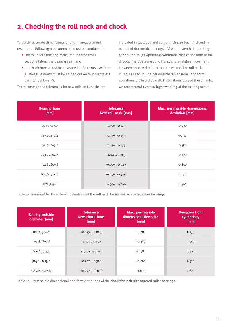
2. Checking the roll neck and chock
To obtain accurate dimensional and form measurement
results, the following measurements must be conducted:
• The roll necks must be measured in three cross
sections (along the bearing seat) and
• the chock bores must be measured in four cross sections.
All measurements must be carried out on four diameters
each (offset by 45°).
The recommended tolerances for new rolls and chocks are
indicated in tables 1a and 1b (for inch-size bearings) and in
1c and 1d (for metric bearings). After an extended operating
period, the rough operating conditions change the form of the
chocks. The operating conditions, and a relative movement
between cone and roll neck cause wear of the roll neck.
In tables 1a to 1d, the permissible dimensional and form
deviations are listed as well. If deviations exceed these limits,
we recommend overhauling/reworking of the bearing seats.
Bearing bore[mm]
ToleranceNew roll neck [mm]
Max. permissible dimensional deviation [mm]
Up to 127,0 -0,100…-0,125 -0,430
127,0…152,4 -0,130…-0,155 -0,510
152,4…203,2 -0,150…-0,175 -0,580
203,2…304,8 -0,180…-0,205 -0,670
304,8…609,6 -0,200…-0,249 -0,850
609,6…914,4 -0,250…-0,334 -1,150
over 914,4 -0,300…-0,400 -1,400
Bearing outside diameter [mm]
ToleranceNew chock bore
[mm]
Max. permissible dimensional deviation
[mm]
Deviation from cylindricity
[mm]
Up to 304,8 +0,055…+0,080 +0,200 0,130
304,8…609,6 +0,101…+0,150 +0,380 0,260
609,6…914,4 +0,156…+0,230 +0,580 0,400
914,4…1219,2 +0,202…+0,300 +0,760 0,510
1219,2…1524,0 +0,257…+0,380 +1,000 0,670
Table 1b: Permissible dimensional and form deviations of the chock for inch-size tapered roller bearings.
Table 1a: Permissible dimensional deviations of the roll neck for inch-size tapered roller bearings.
Montageanleitung_05_E.qxd 08.12.2005 11:10 Uhr Seite 5
6
Bearing bore[mm]
Tolerance New roll neck [mm]
Max. permissible dimensional deviation [mm]
Up to 180 -0,125…-0,175 -0,400
180…315 -0,180…-0,230 -0,650
315…630 -0,240…-0,300 -0,900
630…800 -0,325…-0,410 -1,100
800…1000 -0,350…-0,450 -1,250
over 1000 -0,400…-0,500 -1,450
Bearing outside diameter [mm]
ToleranceNew chock bore
[mm]
Max. permissible dimensional deviation
[mm]
Deviation from cylindricity
[mm]
Up to 315 +0,000/+0,032 (H6) +0,170 0,130
315…400 +0,000/+0,036 (H6) +0,200 0,150
400…500 +0,000/+0,040 (H6) +0,240 0,170
500…630 +0,000/+0,044 (H6) +0,290 0,200
630…800 +0,000/+0,050 (H6) +0,360 0,240
800…1000 +0,000/+0,090 (H7) +0,450 0,300
1000…1250 +0,000/+0,105 (H7) +0,560 0,390
1250…1600 +0,000/+0,125 (H7) +0,690 0,520
Table 1d: Permissible dimensional and form deviations of the chock for metric tapered roller bearings.
Table 1c: Permissible dimensional deviations of the roll neck for metric tapered roller bearings.
Montageanleitung_05_E.qxd 08.12.2005 11:10 Uhr Seite 6

7
3. Arranging the bearing set
Remove the packing from the bearing set. Do not wash
out the anti-corrosion oil. It does not react with any of the
commonly used rolling bearing lubricants.
The bearing set consists of:
2 single-row cups, 1 double-row cup,
2 outer spacers, 2 cones with roller-cage assemblies,
1 inner spacer and with sealed bearings,
2 seal carriers with seals (Fig. 1).
1: Standard design of a sealed four-row tapered roller bearing with marking system
seal carrier A with seal
cup A-B
outer spacer B
cone A-Ca
inner spacer C
double-row cup D-B
inner spacer E-Ce
outer spacer D
cup E-D
seal carrier E with seal
Montageanleitung_05_E.qxd 08.12.2005 11:10 Uhr Seite 7

8
Make sure that the bearing set is complete.
Check the markings on the ring faces. The bearing designation,
the year and the consecutive number must be identical on all
parts. To ensure that the bearing works properly, all parts of
the bearing set must be assembled and mounted in the
order of the letters A to E on the faces of the rings and on the
outside diameters of the spacers (Fig. 1).
The bearing parts must not be interchanged!
4 load zones are marked on the faces of the cups with the
Roman numerals I to IV, offset by 90° each. In addition, the
position of load zone I is marked by an axial etched line on
the outside diameter of the cups. When assembling the
bearing set, make sure that the load zone markings are
aligned in a row (Fig. 2).
2: Markings on the bearing rings
Montageanleitung_05_E.qxd 08.12.2005 11:10 Uhr Seite 8

9
3: Fastening the cover on the roll body side 4: Mounting the cup D-E and spacer D
To protect the bearing seats on the roll neck and in the chock
from fretting corrosion, they must be coated thinly with a
mounting paste (e. g. FAG ARCA.MOUNTINGPASTE).
Please observe the mounting instructions in the mounting
and assembly drawings. Bolt the cover on the roll body side
securely to the chock (Fig. 3).
Place the chock on a level support with the open side up
(vertical axis).
The mounting procedure described in the following depends
on the bearing design (bearings with a pressed cage, bearings
with a pin-type cage or sealed bearings).
Note: In the following mounting instructions, the part currently
being mounted is shown red.
4.1 Mounting the bearing parts
Lift the parts of the bearing set and lower them into the chock
in the specified order, starting with cup D-E. The load zone I
markings on the cups must be aligned. We recommend to posi-
tion load zone I in load direction.
Make sure that adjacent parts abut each other completely and
the seat in the chock does not get damaged by jamming.
Lift the single-row cup marked D-E with side E down and the
outer spacer D into the chock (Fig. 4).
4. Mounting
Montageanleitung_05_E.qxd 08.12.2005 11:10 Uhr Seite 9
10
4a: Completing the bearing set (bearings with a pressed cage) 4b: Mounting the preassembled bearing set
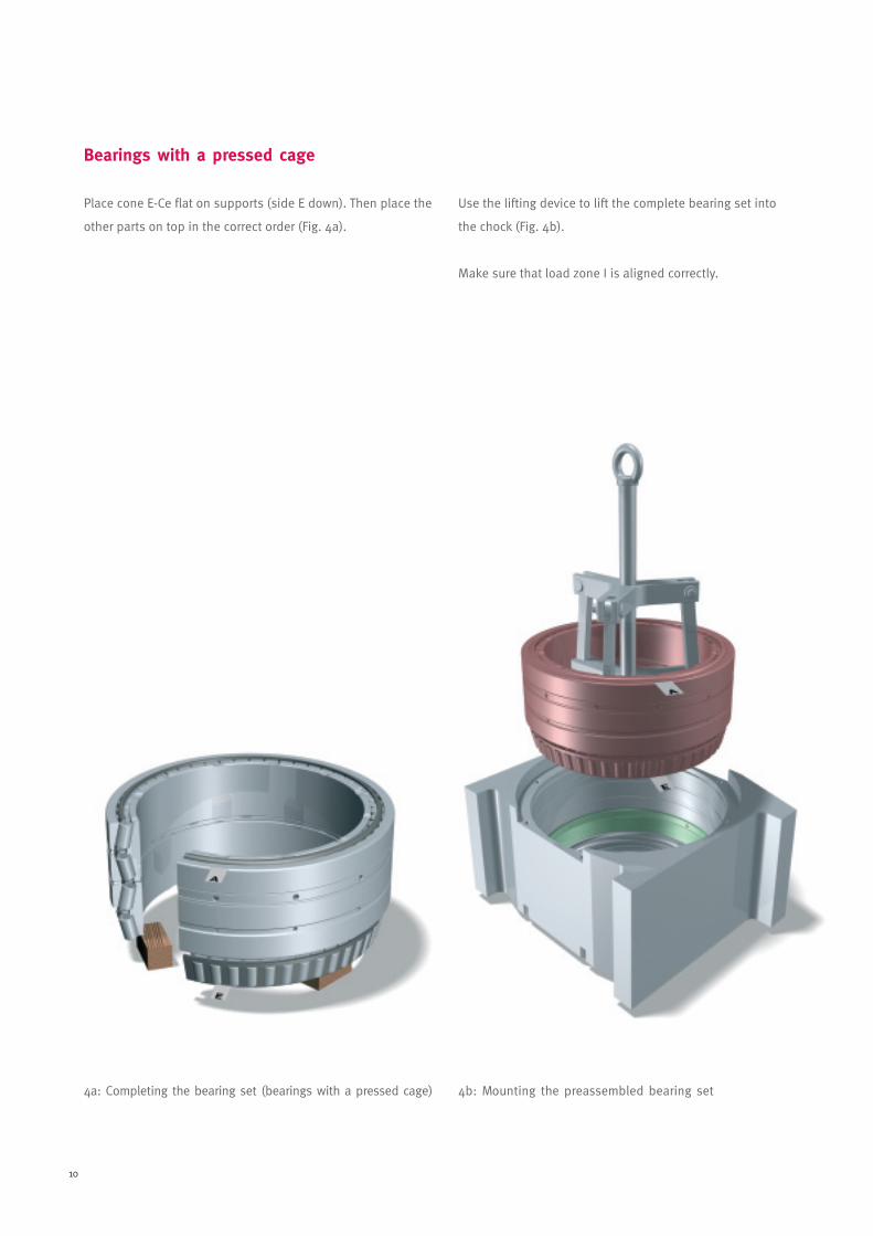
Bearings with a pressed cage
Place cone E-Ce flat on supports (side E down). Then place the
other parts on top in the correct order (Fig. 4a).
Use the lifting device to lift the complete bearing set into
the chock (Fig. 4b).
Make sure that load zone I is aligned correctly.
Montageanleitung_05_E.qxd 08.12.2005 11:10 Uhr Seite 10

11
Bearings with a pin-type cage
Lift cone E-Ce with side E down, the inner spacer C with the
retaining lip down, the double-row cup B-D and the outer
spacer B into the chock (Fig. 5).
Lift cone A-Ca and the single-row cup A-B into the chock (Fig. 6).
Make sure that load zone I is aligned correctly.
Bearings with a pin-type cage can be mounted, like bearings
with a pressed cage, with the help of a lifting device (Fig. 4b).
5: Mounting cone E-Ce, spacer C, cup B-D and spacer B(bearings with a pin-type cage)
6: Mounting cone A-Ca and cup A-B
Montageanleitung_05_E.qxd 08.12.2005 11:10 Uhr Seite 11
12
6a: Mounting a sealed bearing
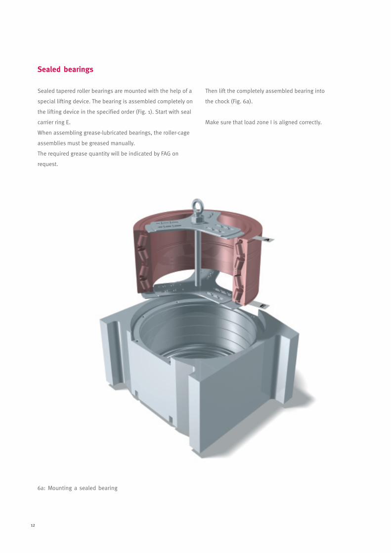
Sealed bearings
Sealed tapered roller bearings are mounted with the help of a
special lifting device. The bearing is assembled completely on
the lifting device in the specified order (Fig. 1). Start with seal
carrier ring E.
When assembling grease-lubricated bearings, the roller-cage
assemblies must be greased manually.
The required grease quantity will be indicated by FAG on
request.
Then lift the completely assembled bearing into
the chock (Fig. 6a).
Make sure that load zone I is aligned correctly.
Montageanleitung_05_E.qxd 08.12.2005 11:10 Uhr Seite 12
13
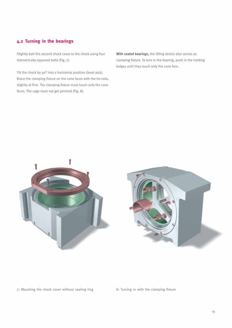
4.2 Turning in the bearings
Slightly bolt the second chock cover to the chock using four
diametrically opposed bolts (Fig. 7).
Tilt the chock by 90° into a horizontal position (level axis).
Brace the clamping fixture on the cone faces with the tie rods,
slightly at first. The clamping fixture must touch only the cone
faces. The cage must not get jammed (Fig. 8).
With sealed bearings, the lifting device also serves as
clamping fixture. To turn in the bearing, push in the holding
ledges until they touch only the cone face.
7: Mounting the chock cover without sealing ring 8: Turning in with the clamping fixture
Montageanleitung_05_E.qxd 08.12.2005 11:10 Uhr Seite 13
14
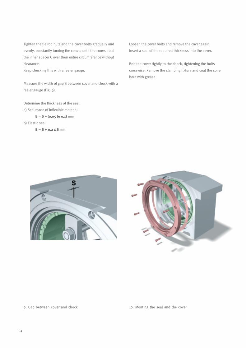
Tighten the tie rod nuts and the cover bolts gradually and
evenly, constantly turning the cones, until the cones abut
the inner spacer C over their entire circumference without
clearance.
Keep checking this with a feeler gauge.
Measure the width of gap S between cover and chock with a
feeler gauge (Fig. 9).
Determine the thickness of the seal.
a) Seal made of inflexible material
B = S – (0,05 to 0,1) mm
b) Elastic seal:
B = S + 0,2 x S mm
Loosen the cover bolts and remove the cover again.
Insert a seal of the required thickness into the cover.
Bolt the cover tightly to the chock, tightening the bolts
crosswise. Remove the clamping fixture and coat the cone
bore with grease.
9: Gap between cover and chock 10: Monting the seal and the cover
Montageanleitung_05_E.qxd 08.12.2005 11:10 Uhr Seite 14

15
11. Mounting the labyrinth ring 12: Pushing the assembled chock onto the roll neck
4.3 Final mounting
Push the labyrinth ring you have heated in an oil bath onto
the roll neck together with the O-ring. While the labyrinth ring
cools down, it must be pressed tightly against the roll body
face (Fig. 11).
Push the assembled chock onto the roll neck (Fig. 12).
Montageanleitung_05_E.qxd 08.12.2005 11:11 Uhr Seite 15
16
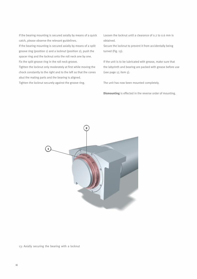
If the bearing mounting is secured axially by means of a quick
catch, please observe the relevant guidelines.
If the bearing mounting is secured axially by means of a split
groove ring (position 1) and a locknut (position 2), push the
spacer ring and the locknut onto the roll neck one by one.
Fix the split groove ring in the roll neck groove.
Tighten the locknut only moderately at first while moving the
chock constantly to the right and to the left so that the cones
abut the mating parts and the bearing is aligned.
Tighten the locknut securely against the groove ring.
Loosen the locknut until a clearance of 0.2 to 0.6 mm is
obtained.
Secure the locknut to prevent it from accidentally being
turned (Fig. 13).
If the unit is to be lubricated with grease, make sure that
the labyrinth and bearing are packed with grease before use
(see page 17, item 5).
The unit has now been mounted completely.
Dismounting is effected in the reverse order of mounting.
13: Axially securing the bearing with a locknut
2
1
Montageanleitung_05_E.qxd 08.12.2005 11:11 Uhr Seite 16
17
5. Lubrication
Grease lubrication
We recommend to lubricate the roll bearings with a lithium
soap base grease with EP (high-pressure) additives and a high
level of corrosion protection (see Arcanol rolling bearing-tested
grease, publication WL 81116).
Unsealed bearings should be greased only after mounting as
otherwise the bearing may get contaminated. Press grease into
the bearing by means of a grease gun until excess grease
escapes on both sides of the bearing over the entire circum-
ference.
If no grease gun is available, the roller-cage assemblies must
be greased manually before being inserted into the chock.
Sealed bearings see page 12.
The required grease quantity for your application will be
indicated on request.
The relubrication interval and the replenishment quantity are
determined for each specific application on the basis of the
prevailing operating conditions.
Oil lubrication
Depending on the operating and environmental conditions,
four-row tapered roller bearings can be operated using the
following oil lubrication methods:
• oil sump
• oil-air (oil mist)
• oil circulation
The required oil quality is determined on a case-to-case basis.
Labyrinth lubrication
When being mounted for the first time, the labyrinths should
be filled well with grease and then relubricated at regular
intervals/on the occasion of roll changes.
The same applies to oil-lubricated bearings.
Montageanleitung_05_E.qxd 08.12.2005 11:11 Uhr Seite 17
18
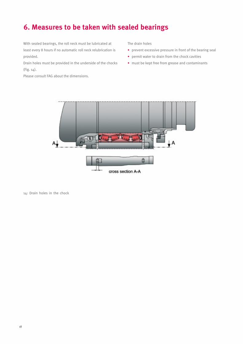
14: Drain holes in the chock
With sealed bearings, the roll neck must be lubricated at
least every 8 hours if no automatic roll neck relubrication is
provided.
Drain holes must be provided in the underside of the chocks
(Fig. 14).
Please consult FAG about the dimensions.
The drain holes
• prevent excessive pressure in front of the bearing seal
• permit water to drain from the chock cavities
• must be kept free from grease and contaminants
6. Measures to be taken with sealed bearings
Montageanleitung_05_E.qxd 08.12.2005 11:11 Uhr Seite 18

19
Check the effectiveness of the chock seals and the temperature
of the bearing regularly. If the bearing works properly, its
temperature increases slowly to operating temperature and
then remains constant. If you detect even the slightest
damage, the seal must be replaced.
FAG recommends an inspection and a shift of load zones after
every 1,000 to 1,200 operating hours.
Dismount the bearings in the reverse order of mounting.
Clean the bearing parts thoroughly with petroleum ether and
oil them immediately afterwards. Check all raceways and
rollers for visible damage.
• If there is any damage in raceways and on rollers:
Consult an FAG engineer.
• Check the axial clearance (see items 8.1 and 8.2).
• Pack the bearing with fresh grease.
• Mount the bearing, in accordance with the mounting
instructions, shifting to the next load zone. The cups
should be turned inside the chock by 180° when changing
load zones the first time. If, for example, load zone I was
aligned in load direction before dismounting, align the
cups in such a way that the load zone III markings are now
aligned in load direction. The next times, turn to load zone
II and then IV.
• Enter all inspections and maintenance work performed
on the bearing in the rolling bearing inspection card
(example on page 25).
With sealed tapered roller bearings, we recommend to per-
form additional inspections after 300, 600 and 900 operating
hours, proceeding as follows:
Withdraw the chock and remove the cover.
• Check the grease quantity and the condition of the grease
in the bearing and in the labyrinths. If the grease is
discoloured or contaminated, we recommend to pack
bearing and labyrinths with fresh grease.
• The bearing seal must be checked carefully and replaced
if even the slightest damage is found.
• Enter the checks and maintenance work in the rolling
bearing inspection card (example on page 25).
7. Maintenance
Montageanleitung_05_E.qxd 08.12.2005 11:11 Uhr Seite 19
20
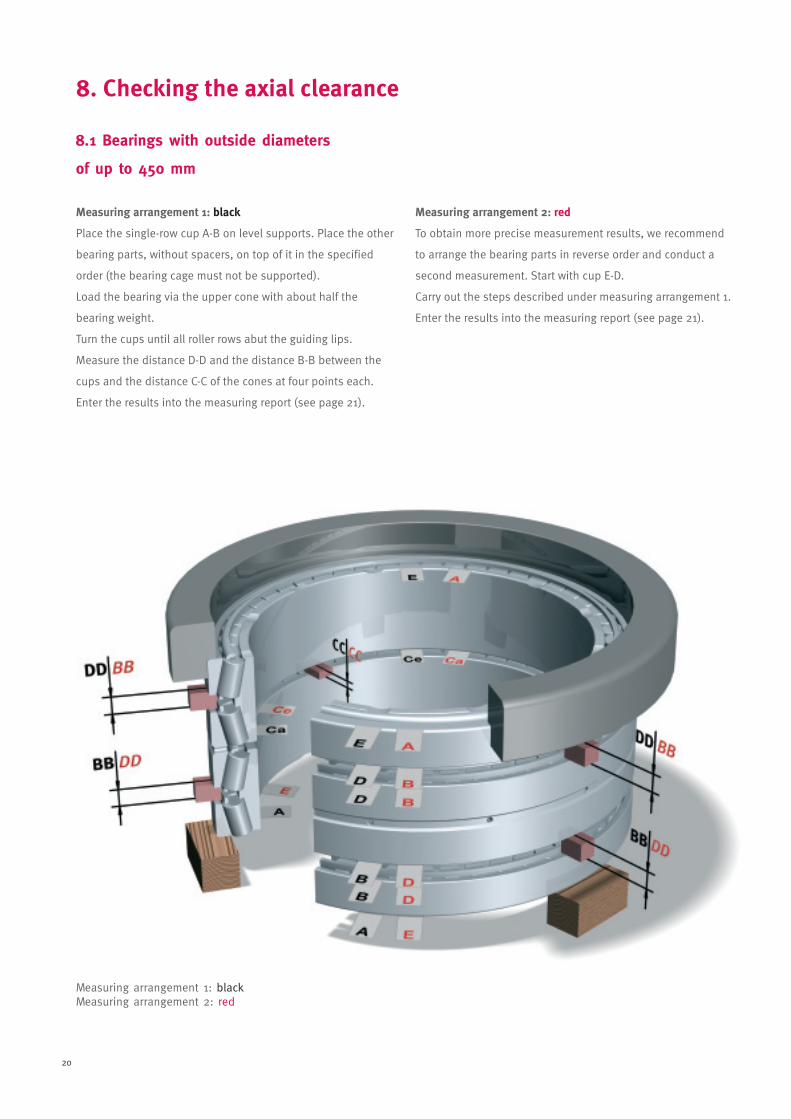
8.1 Bearings with outside diameters
of up to 450 mm
Measuring arrangement 1: black
Place the single-row cup A-B on level supports. Place the other
bearing parts, without spacers, on top of it in the specified
order (the bearing cage must not be supported).
Load the bearing via the upper cone with about half the
bearing weight.
Turn the cups until all roller rows abut the guiding lips.
Measure the distance D-D and the distance B-B between the
cups and the distance C-C of the cones at four points each.
Enter the results into the measuring report (see page 21).
Measuring arrangement 2: red
To obtain more precise measurement results, we recommend
to arrange the bearing parts in reverse order and conduct a
second measurement. Start with cup E-D.
Carry out the steps described under measuring arrangement 1.
Enter the results into the measuring report (see page 21).
Measuring arrangement 1: blackMeasuring arrangement 2: red
8. Checking the axial clearance
Montageanleitung_05_E.qxd 08.12.2005 11:11 Uhr Seite 20
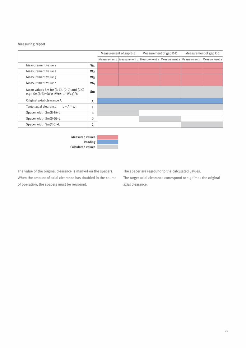
21
Measurement value 1
Measurement 1 Measurement 2 Measurement 1 Measurement 2 Measurement 1 Measurement 2
Measurement of gap B-B Measurement of gap D-D Measurement of gap C-C
Measurement value 2
Measurement value 3
Measurement value 4
Original axial clearance A
Target axial clearance L = A * 1.3
Spacer width Sm(B-B)+L
Spacer width Sm(D-D)+L
Spacer width Sm(C-C)+L
Measured values
Reading
Calculated values
Mean values Sm for (B-B), (D-D) and (C-C)e.g.: Sm(B-B)=(W11+W12+…+W24)/8
W1
W2
W3
W4
Sm
A
L
B
D
C
The value of the original clearance is marked on the spacers.
When the amount of axial clearance has doubled in the course
of operation, the spacers must be reground.
The spacer are reground to the calculated values.
The target axial clearance correspond to 1.3 times the original
axial clearance.
Measuring report
Montageanleitung_05_E.qxd 08.12.2005 11:11 Uhr Seite 21
22
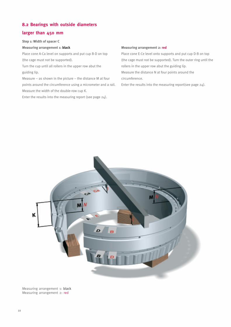
8.2 Bearings with outside diameters
larger than 450 mm
Measuring arrangement 1: blackMeasuring arrangement 2: red
Step 1: Width of spacer C
Measuring arrangement 1: black
Place cone A-Ca level on supports and put cup B-D on top
(the cage must not be supported).
Turn the cup until all rollers in the upper row abut the
guiding lip.
Measure – as shown in the picture – the distance M at four
points around the circumference using a micrometer and a rail.
Measure the width of the double-row cup K.
Enter the results into the measuring report (see page 24).
Measuring arrangement 2: red
Place cone E-Ce level onto supports and put cup D-B on top
(the cage must not be supported). Turn the outer ring until the
rollers in the upper row abut the guiding lip.
Measure the distance N at four points around the
circumference.
Enter the results into the measuring report(see page 24).
Montageanleitung_05_E.qxd 08.12.2005 11:11 Uhr Seite 22
23
Measuring arrangement 1: redMeasuring arrangement 2: black
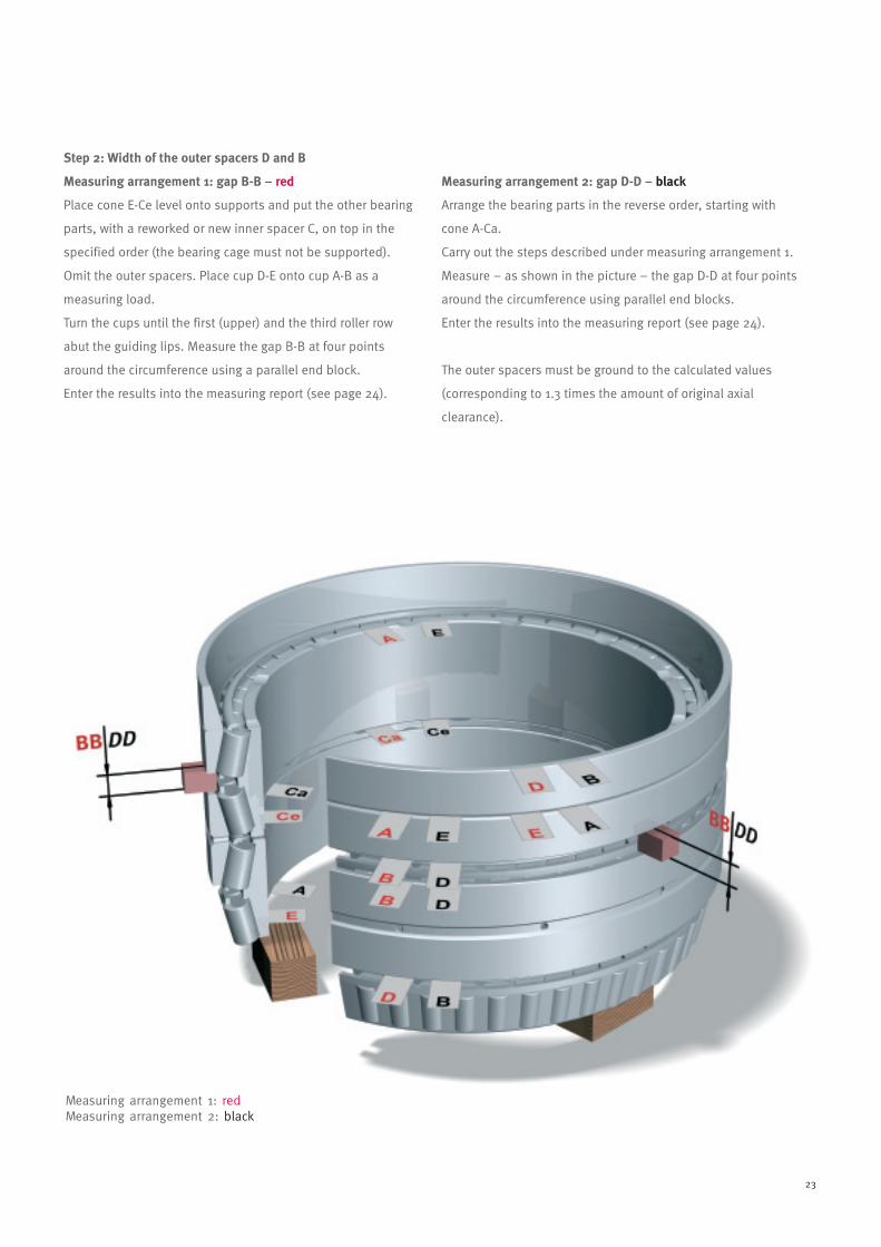
Step 2: Width of the outer spacers D and B
Measuring arrangement 1: gap B-B – red
Place cone E-Ce level onto supports and put the other bearing
parts, with a reworked or new inner spacer C, on top in the
specified order (the bearing cage must not be supported).
Omit the outer spacers. Place cup D-E onto cup A-B as a
measuring load.
Turn the cups until the first (upper) and the third roller row
abut the guiding lips. Measure the gap B-B at four points
around the circumference using a parallel end block.
Enter the results into the measuring report (see page 24).
Measuring arrangement 2: gap D-D – black
Arrange the bearing parts in the reverse order, starting with
cone A-Ca.
Carry out the steps described under measuring arrangement 1.
Measure – as shown in the picture – the gap D-D at four points
around the circumference using parallel end blocks.
Enter the results into the measuring report (see page 24).
The outer spacers must be ground to the calculated values
(corresponding to 1.3 times the amount of original axial
clearance).
Montageanleitung_05_E.qxd 08.12.2005 11:11 Uhr Seite 23
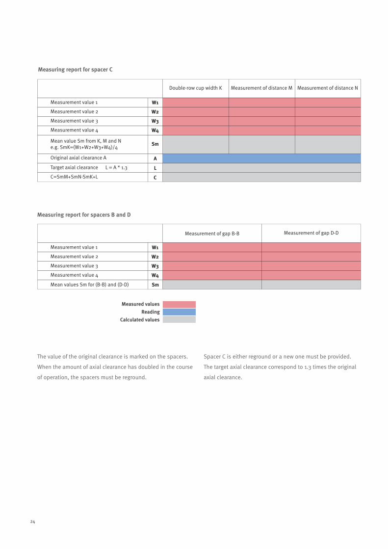
24
Measurement value 1
Double-row cup width K Measurement of distance M Measurement of distance N
Measurement value 2
Measurement value 3
Measurement value 4
Original axial clearance A
Target axial clearance L = A * 1.3
C=SmM+SmN-SmK+L
Mean value Sm from K, M and Ne.g. SmK=(W1+W2+W3+W4)/4
W1
W2
W3
W4
Sm
A
L
C
Measurement value 1
Measurement of gap B-B Measurement of gap D-D
Measurement value 2
Measurement value 3
Measurement value 4
Mean values Sm for (B-B) and (D-D)
W1
W2
W3
W4
Sm
Measured values
Reading
Calculated values
The value of the original clearance is marked on the spacers.
When the amount of axial clearance has doubled in the course
of operation, the spacers must be reground.
Spacer C is either reground or a new one must be provided.
The target axial clearance correspond to 1.3 times the original
axial clearance.
Measuring report for spacer C
Measuring report for spacers B and D
Montageanleitung_05_E.qxd 08.12.2005 11:11 Uhr Seite 24

25
9. Statistical records
On delivery of the bearings, it is advisable to create a record
card for each bearing in order to be able to evaluate the
performance of a bearing more accurately.
An example of such a record card is shown below.
Mill Back-up roll O
Bearing type Bearing No. Serial No.
Bore dia.
Date of order Date of delivery 1 st installation Hrs. total Total (tons)
O. D.Double row Radial Clearance Lubricant
Four-row Axial Clearance Lubr. Intervals WidthInstallNo.
1
2
345
6
7
8
9
10
11
12
13
14
15
16
17
18
19
20
21
∞ i a ∞ i a∞ i a ∞ i a
∞ i a ∞ i a
∞ i a ∞ i a
∞ i a ∞ i a
∞ i a ∞ i a
∞ i a ∞ i a
∞ i a ∞ i a
∞ i a ∞ i a
∞ i a ∞ i a
∞ i a ∞ i a
∞ i a ∞ i a
∞ i a ∞ i a
∞ i a ∞ i a
∞ i a ∞ i a
∞ i a ∞ i a
∞ i a ∞ i a
∞ i a ∞ i a
∞ i a ∞ i a
∞ i a ∞ i a
∞ i a ∞ i a
∞ i a ∞ i a
∞ i a ∞ i a
∞ i a ∞ i a
∞ i a ∞ i a
∞ i a ∞ i a
∞ i a ∞ i a
∞ i a ∞ i a
∞ i a ∞ i a
∞ i a ∞ i a
∞ i a ∞ i a
∞ i a ∞ i a
∞ i a ∞ i a
∞ i a ∞ i a
∞ i a ∞ i a
22
23
24
25
26
27
28
29
30
31
32
33
34
35
For Inspection of Four Row Tapered Roller Bearings
B
C
D
B
C
D
B
C
D
B
C
D
B
C
D
B
C
D
Mounted Dism. StandNo.
Chock No.
Roll No. Loaded zone Drive Side
Inner OuterWith. Side
Inner Outer
Top Roll Bot. Running(hours)
Total run(hrs.)
Production(tons)
Totalproduction
(tons)Remarks
InstallNo.
Mounted Dism. StandNo.
Chock No.
Roll No. Loaded zone Drive Side
Inner OuterWith. Side
Inner Outer
Top Roll Bot. Running(hours)
Total run(hrs.)
Production(tons)
Totalproduction
(tons)Remarks
Date DateGap GapSpacerwidth Clearance Ground
toNew
clearance DateSpacerwidth Clearance Ground
toNew
clearance Gap Spacerwidth Clearance Ground
toNew
clearance
Rolling Bearing Check Card Train Work roll O
Montageanleitung_05_E.qxd 08.12.2005 11:11 Uhr Seite 25

26
10. Storage
Spare bearings should be stored in their original packing, lying
in a dry warehouse, supported over their entire circumference.
Used bearings must be cleaned carefully with petroleum ether,
oiled immediately afterwards, wrapped in oiled paper and
placed in a suitable wooden crate (ideally their original
packing) before being warehoused.
Prior to extended storage periods, grease-lubricated bearings
must be regreased.
If the chocks are withdrawn from the roll neck, they must be
covered to protect the bearings inside from moisture and dirt.
Montageanleitung_05_E.qxd 08.12.2005 11:11 Uhr Seite 26

00/0
1/07
Pri
nted
in G
erm
any
byD
ruck
haus
WEP
PERT
Gm
bH
Schaeffler KG
Heavy Industries
Steel
Georg-Schäfer-Straße 30
97421 Schweinfurt (Germany)
Internet www.fag.com
E-Mail [email protected]
Phone +49 9721 91-0
Fax +49 9721 91-3435
Every care has been taken to ensure the
correctness of the information contained in
this publication but no liability can be
accepted for any errors or omissions.
We reserve the right to make technical
changes.
© Schaeffler KG · 2007, January
This publication or parts thereof may not
be reproduced without our permission.
WL 80 154 EA