foundation fieldbus linking device ld 800hse, user ... · see page 50 specific cautions ... device...
TRANSCRIPT

Power and productivity
for a better worldTM
Device ManagementFOUNDATION Fieldbus Linking Device, LD 800HSE and LD 800HSE EX, V3.6.0/0


Device ManagementFOUNDATION Fieldbus Linking Device,
LD 800HSE and LD 800HSE EX,V3.6.0/0

NOTICEThis document contains information about one or more ABB products and may include adescription of or a reference to one or more standards that may be generally relevant tothe ABB products. The presence of any such description of a standard or reference to astandard is not a representation that all of the ABB products referenced in this documentsupport all of the features of the described or referenced standard. In order to determinethe specific features supported by a particular ABB product, the reader should consult theproduct specifications for the particular ABB product.
ABB may have one or more patents or pending patent applications protecting the intel-lectual property in the ABB products described in this document.
The information in this document is subject to change without notice and should not beconstrued as a commitment by ABB. ABB assumes no responsibility for any errors thatmay appear in this document.
In no event shall ABB be liable for direct, indirect, special, incidental or consequentialdamages of any nature or kind arising from the use of this document, nor shall ABB beliable for incidental or consequential damages arising from use of any software or hard-ware described in this document.
This document and parts thereof must not be reproduced or copied without written per-mission from ABB, and the contents thereof must not be imparted to a third party nor usedfor any unauthorized purpose.
The software or hardware described in this document is furnished under a license andmay be used, copied, or disclosed only in accordance with the terms of such license. Thisproduct meets the requirements specified in EMC Directive 2004/108/EC, Low VoltageDirective 2006/95/EC and the hardware used in hazardous areas comply with ATEX di-rective 94/9/EC.
TRADEMARKSAll rights to copyrights, registered trademarks, and trademarks reside with their respec-tive owners.
Copyright © 2003-2014 by ABB. All rights reserved.
Release: August 2014Document number: 3BDD011677-600 A
3BDD011677-600 A 5
Table of Contents
About this User ManualUser Manual Conventions ...............................................................................................11
Warning, Caution, Information, and Tip Icons ....................................................11
Terminology.....................................................................................................................12
Released User Manuals and Release Notes.....................................................................13
Section 1 - IntroductionFeatures of the Linking Device .......................................................................................15
Integration into the Industrial IT System Structure .........................................................18
New in This Release ........................................................................................................20
Prerequisites and Requirements .....................................................................................20
Product Support ...............................................................................................................20
Section 2 - Hardware InstallationRestrictions ......................................................................................................................21
Mounting and Dismounting.............................................................................................23
Installation in Hazardous Locations ................................................................................25
Hazardous Location - North American Approval (cULus)..................................25
Hazardous Location - European and International Approval (ATEX, IECEx)....26
Interfaces and Display Elements ....................................................................................27
Interfaces .............................................................................................................27
Power Supply ......................................................................................27
Grounding ......................................................................................28
Serial Interface ....................................................................................28
10/100 Mbit/s Ethernet Port (HSE High Speed Ethernet Port)...........29
FF H1 Fieldbus Connection ................................................................30
Table of Contents
6 3BDD011677-600 A
Display Elements ................................................................................................. 32
Device Status Indication ..................................................................... 33
Status Indications of the four H1 Channels ........................................ 42
Commissioning the Hardware......................................................................................... 44
Replacing a Defective Linking Device in a Redundant Set of Linking Devices ............ 45
Adding a Second Linking Device to form a Redundant Set of Linking Devices ........... 46
Section 3 - ConfigurationCommunication Settings ................................................................................................. 47
Setting Up an IP Connection between PC and Linking Device........................... 50
Assignment of a Second (Local) IP Address ...................................... 52
System Settings ............................................................................................................... 56
Login to Web Server Interface ............................................................................. 56
Network Configuration ....................................................................... 61
Firmware Update ............................................................................. 65
RAM Test Configuration .................................................................... 71
Password ...................................................................................... 71
Plant Configuration and Commissioning ........................................................................ 72
Using a Redundant Set of Linking Devices ......................................................... 73
Support for Multi User Engineering .................................................................... 74
Speed up of Device Assignment .......................................................................... 74
Section 4 - Linking Device DiagnosticsPower-on Self Tests......................................................................................................... 75
Test Cases ............................................................................................................ 75
Test Results .......................................................................................................... 76
Built-in Web Server......................................................................................................... 76
System Status ....................................................................................................... 79
System Diagnostics.............................................................................................. 82
H1 Diagnostics..................................................................................................... 84
Hardware Diagnostics.......................................................................................... 86
Version Information ............................................................................................. 87
Linking Device Web Server Diagnostics ............................................................. 88

Table of Contents
3BDD011677-600 A 7
3BDD011677-600 A 7
Clearing the Log Files .........................................................................90
Clearing the Error Buffer ....................................................................91
Statistic Information............................................................................92
Internal Device Information ................................................................93
Appendix B - Limits and Performance DataLimits of the Linking Device on HSE .............................................................................97
Maximum Limits..................................................................................................97
Performance of HSE communication...................................................................97
Limits per H1 Channel ....................................................................................................98
General Maximum Limits ....................................................................................98
Performance .........................................................................................................99
H1 Slot Time ........................................................................................................99
Duration of Redundancy Switch-over .............................................................................99
Device Redundancy .......................................................................................................100
Appendix C - Technical ReferenceSupported HSE Services................................................................................................103
Supported H1 Services ..................................................................................................104
HSE Object Dictionary..................................................................................................105
H1 Interface Object Dictionary .....................................................................................107
Data Format for Schedule Domain................................................................................109
Schedule Summary.............................................................................................110
Sub-Schedule......................................................................................................111
Sequence ...........................................................................................................111
Sequence Element ..............................................................................................111
Redundancy ...................................................................................................................112
Redundancy Concept..........................................................................................112
Fault Domain......................................................................................................114
Redundancy Behavior ........................................................................................117
Appendix D - Linking Device for Zone 2 Explosion and Protection Environment
Table of Contents
8 3BDD011677-600 A
General Requirements ................................................................................................... 125
Commissioning and Installation.................................................................................... 126
Linking Device Usage ................................................................................................... 128
Maintenance and Repair................................................................................................ 129
Appendix E - Glossary
Revision HistoryUpdates in Revision Index - .......................................................................................... 133
Updates in Revision Index A......................................................................................... 134
3BDD011677-600 A 9
Safety Summary (continued)
GENERAL WARNINGS
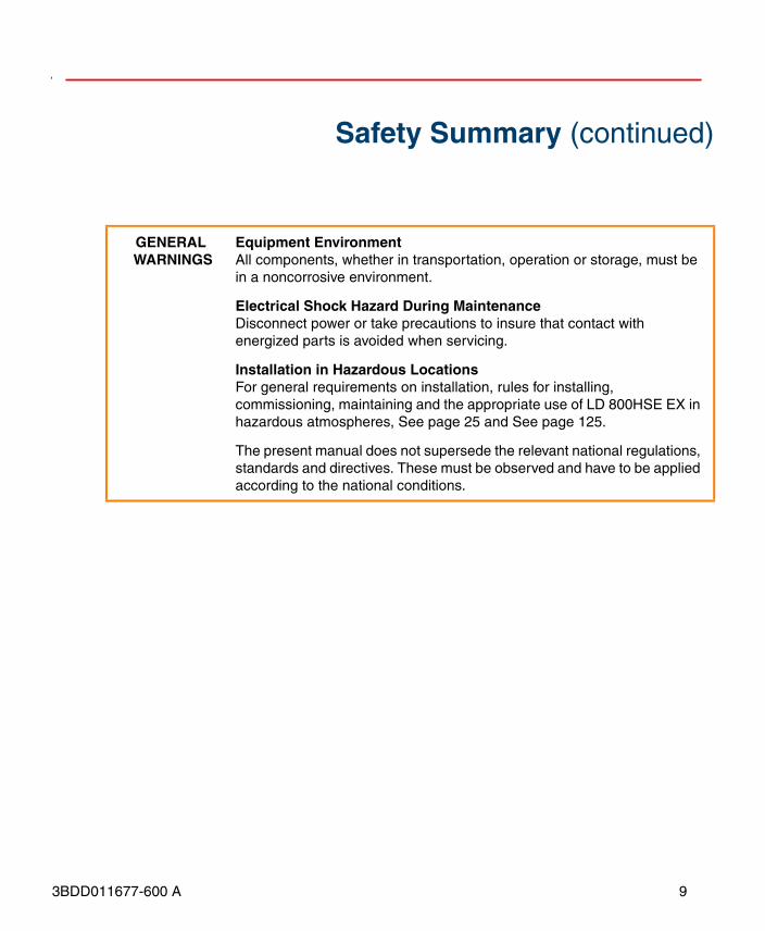
Equipment EnvironmentAll components, whether in transportation, operation or storage, must be in a noncorrosive environment.
Electrical Shock Hazard During MaintenanceDisconnect power or take precautions to insure that contact with energized parts is avoided when servicing.
Installation in Hazardous LocationsFor general requirements on installation, rules for installing, commissioning, maintaining and the appropriate use of LD 800HSE EX in hazardous atmospheres, See page 25 and See page 125.
The present manual does not supersede the relevant national regulations, standards and directives. These must be observed and have to be applied according to the national conditions.

10 3BDD011677-600 A
Safety Summary (continued)
SPECIFIC CAUTIONS
In a redundant set of linking devices, removing the power supply, the Ethernet cable from the Primary Device causes a redundancy change-over. Before doing so, make sure that the Secondary Device is opera-tional (and not still booting due to a prior change-over). Otherwise the system breaks down or the configuration information might get lost. Therefore wait at least one minute between such checks. See page 44
In case of removing the RS-232 cable only, redundancy is being lost but no redundancy switch-over is done.
Make sure that the RS-232 cable is connected before plugging in the power terminal block.If the replaced linking device is powered while the serial link is missing, it will behave like an independent, non-redundant Primary Device. If in this case the linking device has a valid (possibly unknown) configuration, it might use H1 node addresses which are already in use on the H1 links. This will disturb or interrupt communication and application processing on the H1 links. See page 45
Before connecting the linking device to your LAN network, make sure that its IP address is not used by another network station. See page 50
SPECIFIC CAUTIONS
After a firmware update (flash memory update), all FF configuration data will be lost, but the IP configuration is still valid. See page 66
Make sure that in your configuration the maximum number of republished signals per second per H1 link is not exceeded. See page 99
Detecting a loss of an H1 connection between the Primary Device and the entire H1 link requires that at least two H1 devices have been connected to that H1 channel of the linking device and have appeared in the H1 Live List before the loss of the connection occurs. See page 114
Only one of the listed faults may be present at a time. Another fault cannot be tolerated until the redundant set has been repaired and a fully opera-tional Secondary Device is available. See page 115
About this User Manual User Manual Conventions
3BDD011677-600 A 11
About this User Manual
This user manual describes the hardware installation, configuration, and handling of FOUNDATION Fieldbus Linking Device LD 800HSE; non-hazardous (LD 800HSE) and for hazardous areas (LD 800HSE EX). The configuration, handling, and functionality is same for both versions. Hence, they are commonly referred to as LD 800HSE throughout this manual. In case of specific considerations for hazardous areas LD 800HSE EX is explicitly stated.
The reader should have a basic understanding of the FOUNDATION Fieldbus system architecture and communications protocol.
User Manual ConventionsMicrosoft Windows conventions are normally used for the standard presentation of material when entering text, key sequences, prompts, messages, menu items, screen elements, etc.
Warning, Caution, Information, and Tip Icons
This User Manual includes Warning, Caution, and Information where appropriate to point out safety related or other important information. It also includes Tip to point
Any security measures described in this User Manual, for example, for user access, password security, network security, firewalls, virus protection, etc., represent possible steps that a user of an 800xA System may want to consider based on a risk assessment for a particular application and installation. This risk assessment, as well as the proper implementation, configuration, installation, operation, administration, and maintenance of all relevant security related equipment, software, and procedures, are the responsibility of the user of the 800xA System.
Terminology About this User Manual
12 3BDD011677-600 A
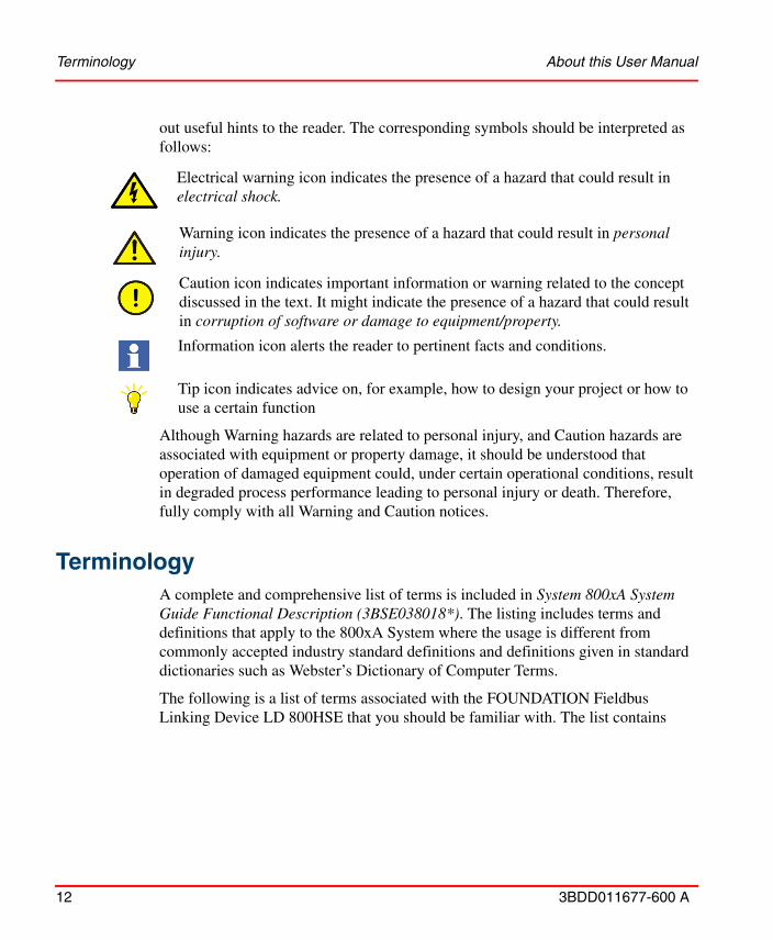
out useful hints to the reader. The corresponding symbols should be interpreted as follows:
Although Warning hazards are related to personal injury, and Caution hazards are associated with equipment or property damage, it should be understood that operation of damaged equipment could, under certain operational conditions, result in degraded process performance leading to personal injury or death. Therefore, fully comply with all Warning and Caution notices.
TerminologyA complete and comprehensive list of terms is included in System 800xA System Guide Functional Description (3BSE038018*). The listing includes terms and definitions that apply to the 800xA System where the usage is different from commonly accepted industry standard definitions and definitions given in standard dictionaries such as Webster’s Dictionary of Computer Terms.
The following is a list of terms associated with the FOUNDATION Fieldbus Linking Device LD 800HSE that you should be familiar with. The list contains
Electrical warning icon indicates the presence of a hazard that could result in electrical shock.
Warning icon indicates the presence of a hazard that could result in personal injury.
Caution icon indicates important information or warning related to the concept discussed in the text. It might indicate the presence of a hazard that could result in corruption of software or damage to equipment/property.
Information icon alerts the reader to pertinent facts and conditions.
Tip icon indicates advice on, for example, how to design your project or how to use a certain function
About this User Manual Released User Manuals and Release Notes
3BDD011677-600 A 13
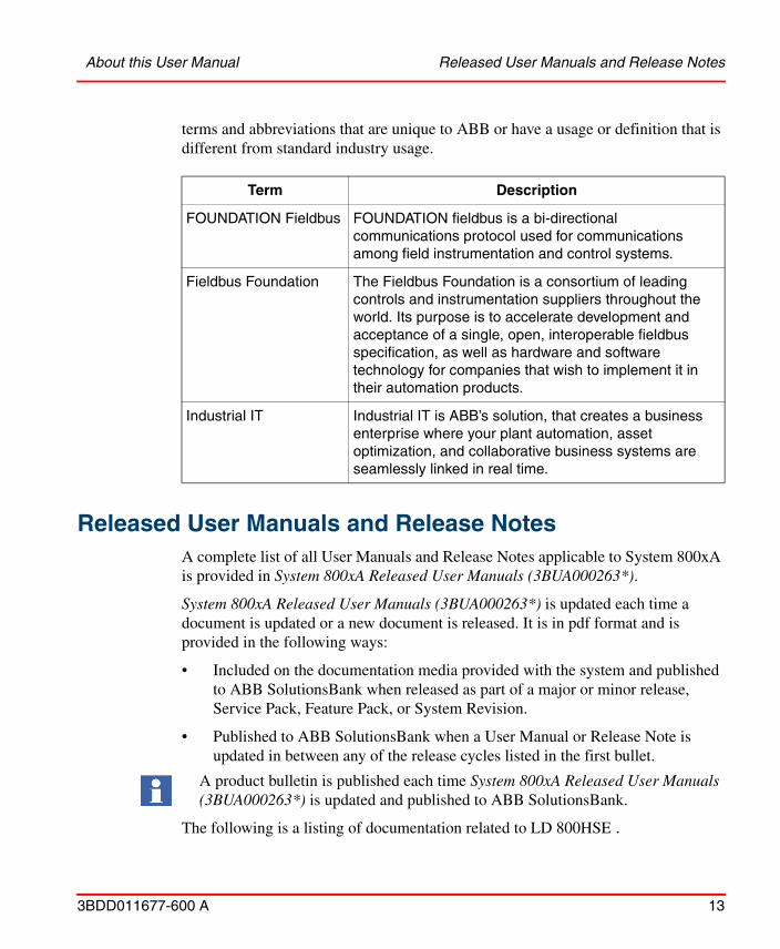
terms and abbreviations that are unique to ABB or have a usage or definition that is different from standard industry usage.
Released User Manuals and Release NotesA complete list of all User Manuals and Release Notes applicable to System 800xA is provided in System 800xA Released User Manuals (3BUA000263*).
System 800xA Released User Manuals (3BUA000263*) is updated each time a document is updated or a new document is released. It is in pdf format and is provided in the following ways:
• Included on the documentation media provided with the system and published to ABB SolutionsBank when released as part of a major or minor release, Service Pack, Feature Pack, or System Revision.
• Published to ABB SolutionsBank when a User Manual or Release Note is updated in between any of the release cycles listed in the first bullet.
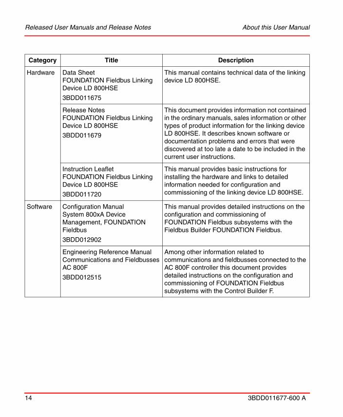
The following is a listing of documentation related to LD 800HSE .
Term Description
FOUNDATION Fieldbus FOUNDATION fieldbus is a bi-directional communications protocol used for communications among field instrumentation and control systems.
Fieldbus Foundation The Fieldbus Foundation is a consortium of leading controls and instrumentation suppliers throughout the world. Its purpose is to accelerate development and acceptance of a single, open, interoperable fieldbus specification, as well as hardware and software technology for companies that wish to implement it in their automation products.
Industrial IT Industrial IT is ABB’s solution, that creates a business enterprise where your plant automation, asset optimization, and collaborative business systems are seamlessly linked in real time.
A product bulletin is published each time System 800xA Released User Manuals (3BUA000263*) is updated and published to ABB SolutionsBank.
Released User Manuals and Release Notes About this User Manual
14 3BDD011677-600 A
Category Title Description
Hardware Data SheetFOUNDATION Fieldbus Linking Device LD 800HSE
3BDD011675
This manual contains technical data of the linking device LD 800HSE.
Release NotesFOUNDATION Fieldbus Linking Device LD 800HSE
3BDD011679
This document provides information not contained in the ordinary manuals, sales information or other types of product information for the linking device LD 800HSE. It describes known software or documentation problems and errors that were discovered at too late a date to be included in the current user instructions.
Instruction LeafletFOUNDATION Fieldbus Linking Device LD 800HSE
3BDD011720
This manual provides basic instructions for installing the hardware and links to detailed information needed for configuration and commissioning of the linking device LD 800HSE.
Software Configuration ManualSystem 800xA Device Management, FOUNDATION Fieldbus
3BDD012902
This manual provides detailed instructions on the configuration and commissioning of FOUNDATION Fieldbus subsystems with the Fieldbus Builder FOUNDATION Fieldbus.
Engineering Reference ManualCommunications and FieldbussesAC 800F
3BDD012515
Among other information related to communications and fieldbusses connected to the AC 800F controller this document provides detailed instructions on the configuration and commissioning of FOUNDATION Fieldbus subsystems with the Control Builder F.

Section 1 Introduction Features of the Linking Device
3BDD011677-600 A 15
Section 1 Introduction
FOUNDATION Fieldbus (FF) is a fieldbus protocol based on international standards and designed for applications in the manufacturing industry, process automation and buildings automation. The guidelines for this fieldbus standard are published by the Fieldbus Foundation.
FF defines two communication profiles, H1 and HSE. The H1 profile, with a transmission rate of 31.25 kbit/s, is preferably used for direct communication between field devices in one link (H1 link). The HSE profile, which is based on standard Ethernet and typically features a transmission rate of 100 Mbit/s, serves first and foremost as a powerful backbone for the connection between H1 links. The first devices that are already available on the market and support the HSE profile are FF linking devices. They serve as a gateway between the field devices on the H1 links and the HSE subnet.
Features of the Linking DeviceThe LD 800HSE is a gateway between an FF High Speed Ethernet (FF-HSE) subnet and FF-H1 links. It supports device redundancy.
The linking device is registered as class 42c of the HSE profile, therefore providing the following functions:
• It supports up to four separate galvanically isolated FF-H1 links. In each of these links, the linking device operates as the Link Master as well as the SM Time Publisher
• Identification of devices connected to the H1 links
• Configuration of connected H1 devices through System Management and Network Management via HSE
• Access to the function blocks of connected H1 devices via HSE
• Republishing of process data between H1 links
• Republishing of process data from H1 to HSE and vice versa

Features of the Linking Device Section 1 Introduction
16 3BDD011677-600 A
• Distribution of alarms and events sent by H1 devices
Functionality in the HSE subnet:
• System Management Agent
• Network Management Agent
• Server providing object access to H1 devices
• Publishing/Subscribing of process data from/to H1 devices
• Distribution of alarms and events sent by H1 devices
• Time synchronization via SNTP
• IP address configurable via integrated web server
Figure 1. Linking Device Communication
Section 1 Introduction Features of the Linking Device
3BDD011677-600 A 17
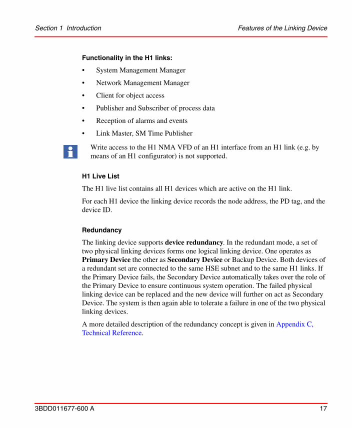
Functionality in the H1 links:
• System Management Manager
• Network Management Manager
• Client for object access
• Publisher and Subscriber of process data
• Reception of alarms and events
• Link Master, SM Time Publisher
H1 Live List
The H1 live list contains all H1 devices which are active on the H1 link.
For each H1 device the linking device records the node address, the PD tag, and the device ID.
Redundancy
The linking device supports device redundancy. In the redundant mode, a set of two physical linking devices forms one logical linking device. One operates as Primary Device the other as Secondary Device or Backup Device. Both devices of a redundant set are connected to the same HSE subnet and to the same H1 links. If the Primary Device fails, the Secondary Device automatically takes over the role of the Primary Device to ensure continuous system operation. The failed physical linking device can be replaced and the new device will further on act as Secondary Device. The system is then again able to tolerate a failure in one of the two physical linking devices.
A more detailed description of the redundancy concept is given in Appendix C, Technical Reference.
Write access to the H1 NMA VFD of an H1 interface from an H1 link (e.g. by means of an H1 configurator) is not supported.

Integration into the Industrial IT System Structure Section 1 Introduction
18 3BDD011677-600 A
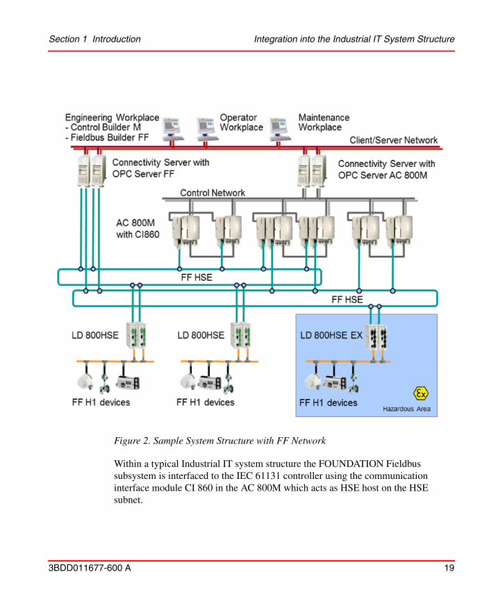
Integration into the Industrial IT System StructureWithin a typical Industrial IT system structure as shown in Figure 2, a FOUNDATION Fieldbus subsystem is linked to the control system via the HSE subnet. The linking devices LD 800HSE serve as gateways between the field devices on the H1 links and the HSE subnet. The FOUNDATION Fieldbus subsystem consists of linking devices and possibly other devices which communicate with one another using the HSE protocol and subsidiary H1 links. As a device registered as a class 42c device of the HSE profile the LD 800HSE allows process data that are being published cyclically on the subsidiary H1 links to be republished on the HSE subnet. By using HSE republishing, it is possible to configure cyclical communication between field devices on different H1 links and devices on the HSE subnet. Furthermore alarms and events from H1 devices are communicated to the Connectivity Servers FF, thus allowing seamless integration in the overall 800xA alarm management philosophy.
The displayed system structure also includes redundant LD 800HSE. The corresponding H1 ports of both physical linking devices making up a redundant set of linking devices are connected to the same H1 link. Both physical devices belonging to a redundant set are connected via a serial RS-232 null modem cable for exchanging redundancy control information.
Section 1 Introduction Integration into the Industrial IT System Structure
3BDD011677-600 A 19
Within a typical Industrial IT system structure the FOUNDATION Fieldbus subsystem is interfaced to the IEC 61131 controller using the communication interface module CI 860 in the AC 800M which acts as HSE host on the HSE subnet.
Figure 2. Sample System Structure with FF Network
New in This Release Section 1 Introduction
20 3BDD011677-600 A
It is also possible to configure and commission an FF network which is not linked to an IEC 61131 controller.
New in This Release• Increase in security of linking device - Linking Device web server is password
protected and must be changed from the default password.
• Zone 2 Environment - Support of Linking device type LD 800HSE EX on Zone 2 Explosion and Protection Environment.
Prerequisites and Requirements
For obtaining firmware and capabilities file, refer to Section 2, Hardware Installation.
Product SupportContact ABB technical support for assistance in reporting the problem.
Before commissioning of LD 800HSE make sure to use the latest linking device firmware released for your system environment.
It is required that all applicable revisions and rollups for your system are installed either previously or at the same time this firmware is installed. Industrial IT System 800xA SV 5.x System Software Versions (3BSE037782R5001) lists all the revisions and rollups released for the above system version and includes links to the revisions and rollups and associated release notes.
Refer to the LD 800HSE and LD 800HSE EX Version Table (3BDS009910) in the ABB SolutionsBank to find out the latest linking device firmware released for your system environment.
Section 2 Hardware Installation Restrictions
3BDD011677-600 A 21
Section 2 Hardware Installation
Additional information regarding this product is available in ABB SolutionsBank. Firmware releases and the corresponding capabilities files are also available for download in the ABB SolutionsBank.
• To obtain the firmware search for document number 3BDS009909*.
• To obtain the capabilities file search for document number 3BDS009371*.
RestrictionsThere exist various hardware versions of the FF Linking Device LD 800HSE with different article numbers as listed below.
Before commissioning of LD 800HSE make sure to use the latest linking device firmware released for your system environment.
It is required that all applicable revisions and rollups for your system are installed either previously or at the same time this firmware is installed. Industrial IT System 800xA SV 5.x System Software Versions (3BSE037782*) lists all the revisions and rollups released for the above system version and includes links to the revisions and rollups and associated release notes.
Refer to the LD 800HSE and LD 800HSE EX Version Table (3BDS009910) in the ABB SolutionsBank to find out the latest linking device firmware released for your system environment.
You can look up the hardware version and the article number of the device on the type plate.
Restrictions Section 2 Hardware Installation
22 3BDD011677-600 A
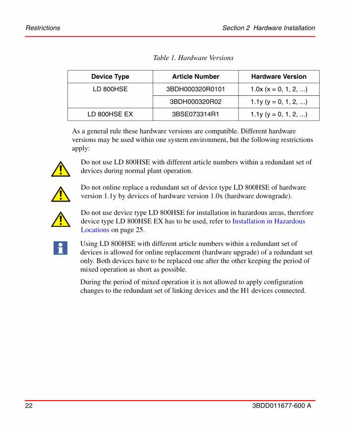
As a general rule these hardware versions are compatible. Different hardware versions may be used within one system environment, but the following restrictions apply:
Table 1. Hardware Versions
Device Type Article Number Hardware Version
LD 800HSE 3BDH000320R0101 1.0x (x = 0, 1, 2, ...)
3BDH000320R02 1.1y (y = 0, 1, 2, ...)
LD 800HSE EX 3BSE073314R1 1.1y (y = 0, 1, 2, ...)
Do not use LD 800HSE with different article numbers within a redundant set of devices during normal plant operation.
Do not online replace a redundant set of device type LD 800HSE of hardware version 1.1y by devices of hardware version 1.0x (hardware downgrade).
Do not use device type LD 800HSE for installation in hazardous areas, therefore device type LD 800HSE EX has to be used, refer to Installation in Hazardous Locations on page 25.
Using LD 800HSE with different article numbers within a redundant set of devices is allowed for online replacement (hardware upgrade) of a redundant set only. Both devices have to be replaced one after the other keeping the period of mixed operation as short as possible.
During the period of mixed operation it is not allowed to apply configuration changes to the redundant set of linking devices and the H1 devices connected.
Section 2 Hardware Installation Mounting and Dismounting
3BDD011677-600 A 23
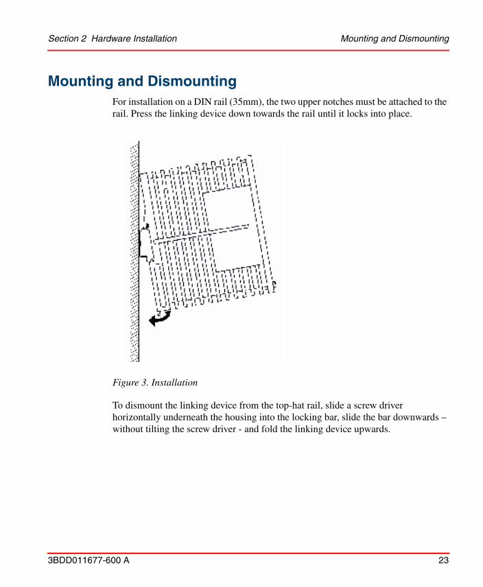
Mounting and DismountingFor installation on a DIN rail (35mm), the two upper notches must be attached to the rail. Press the linking device down towards the rail until it locks into place.
To dismount the linking device from the top-hat rail, slide a screw driver horizontally underneath the housing into the locking bar, slide the bar downwards – without tilting the screw driver - and fold the linking device upwards.
Figure 3. Installation
Mounting and Dismounting Section 2 Hardware Installation
24 3BDD011677-600 A
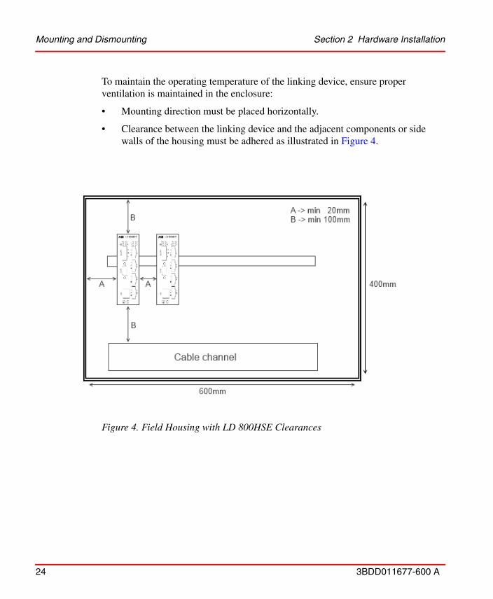
To maintain the operating temperature of the linking device, ensure proper ventilation is maintained in the enclosure:
• Mounting direction must be placed horizontally.
• Clearance between the linking device and the adjacent components or side walls of the housing must be adhered as illustrated in Figure 4.
Figure 4. Field Housing with LD 800HSE Clearances

Section 2 Hardware Installation Installation in Hazardous Locations
3BDD011677-600 A 25
Installation in Hazardous LocationsThe linking device LD 800HSE EX is suitable for use and installation in areas with potentially explosive atmosphere in accordance to the Division model (North America) and the Zone model (Europe and IEC countries) of hazardous locations.
Hazardous Location - North American Approval (cULus)
If indicated on the device label linking device LD 800HSE EX is suitable for use in Class 1, Division 2, Groups A, B, C and D or non-hazardous locations.
The device must be installed in a protective enclosure which meets the requirements for resistance to impact and IP54 according to IEC 60529. Furthermore provision is made to prevent transient disturbances of more than 40% of rated voltage at the power supply terminals.
This manual does not supersede the relevant national regulations, standards and directives. These must be observed and have to be applied according to the national conditions.
Do not use LD 800HSE in hazardous areas, only LD 800HSE EX is suitable to be used in areas with potentially explosive atmospheres. Check device label for device type and marking for explosion protection.
Marking for explosion Protection
Class I Div.2 Groups A,B,C,D
Standards: ANSI/ISA 12.12.01, 2012, Nonincendive Electrical Equipment for Use in Class I and II, Division 2 and Class III, Division 1 and 2 Hazardous (Classified) Locations
CAN/CSA C22.2 No. 213-M1987, Non-incendive Electrical Equipment for Use in Class I, Division 2 Hazardous Locations
UL 508, Industrial Control equipment
CAN/CSA C22.2 No. 142-M1987, Process Control Equipment Industrial Products
Hazardous Location - European and International Approval (ATEX, IECEx) Section 2 Hardware
26 3BDD011677-600 A
Hazardous Location - European and International Approval (ATEX, IECEx)
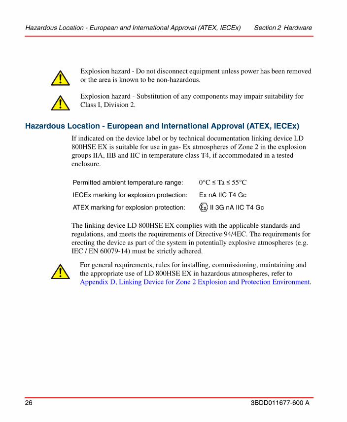
If indicated on the device label or by technical documentation linking device LD 800HSE EX is suitable for use in gas- Ex atmospheres of Zone 2 in the explosion groups IIA, IIB and IIC in temperature class T4, if accommodated in a tested enclosure.
The linking device LD 800HSE EX complies with the applicable standards and regulations, and meets the requirements of Directive 94/4EC. The requirements for erecting the device as part of the system in potentially explosive atmospheres (e.g. IEC / EN 60079-14) must be strictly adhered.
Explosion hazard - Do not disconnect equipment unless power has been removed or the area is known to be non-hazardous.
Explosion hazard - Substitution of any components may impair suitability for Class I, Division 2.
Permitted ambient temperature range: 0°C ≤ Ta ≤ 55°C
IECEx marking for explosion protection: Ex nA IIC T4 Gc
ATEX marking for explosion protection: II 3G nA IIC T4 Gc
‘
For general requirements, rules for installing, commissioning, maintaining and the appropriate use of LD 800HSE EX in hazardous atmospheres, refer to Appendix D, Linking Device for Zone 2 Explosion and Protection Environment.

Section 2 Hardware Installation Interfaces and Display Elements
3BDD011677-600 A 27
Interfaces and Display Elements
Interfaces
Power Supply
The supply voltage (24V DC ± 20%) is connected by a 3-pole terminal block.
Wire diameter: 0.2 – 2.5 mm2, AWG 24-12
Figure 5. Overview interfaces and display elements

Interfaces Section 2 Hardware Installation
28 3BDD011677-600 A
Replacement parts for the terminal block can be obtained from PHOENIX CONTACT (http://www.phoenixcontact.com), type MSTB 2,5/3-STF.
Grounding
A separate screw connection is available for grounding at the bottom part of the front panel. To meet the EMC requirements a low inductance connection between this screw and ground potential is required.
All shield contacts of COM, HSE, and H1 fieldbus ports, the ground contact of the power supply interface, the separate grounding screw connection, and the housing are interconnected.
Serial Interface
The serial interface RS-232 is not galvanically isolated.
Figure 6. Pin assignment of the terminal block for power supply
For maximum EMC protection the shields of all interface cables should be connected to ground potential via a low inductance connection.

Section 2 Hardware Installation Interfaces
3BDD011677-600 A 29
The maximum cable length is 3 m according to EMC requirements.
The baud rate is pre-configured to 115.2 kbit/s.
When using two linking devices as a redundant set, the serial interfaces of both linking devices must be connected by a null modem cable (Article No: 3BDH000281R1), thus forming a “redundancy link”. If the redundancy link is not installed during start-up (power-on), the linking devices will operate in non-redundant mode.
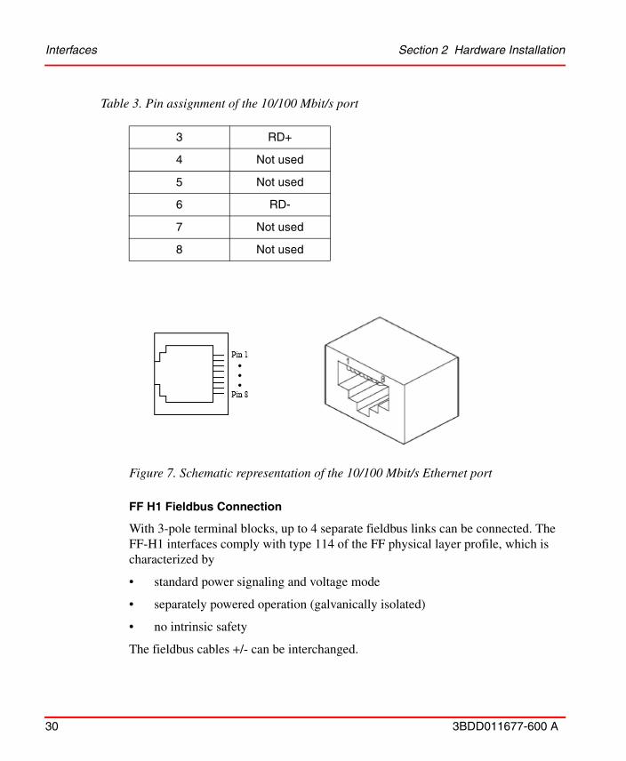
10/100 Mbit/s Ethernet Port (HSE High Speed Ethernet Port)
The Ethernet port corresponds to the standards IEEE 802.3 100BASE-TX/10BASE-T and supports auto negotiation.
The pin assignment corresponds to MDI (Medium Dependent Interface).
Table 2. Pin assignment of the serial interface
Pin Signal
1 CD
2 RXD
3 TXD
4 DTR
5 GND
6 DSR
7 RTS
8 CTS
9 RI
Table 3. Pin assignment of the 10/100 Mbit/s port
Pin MDI Signal
1 TD+
2 TD-
Interfaces Section 2 Hardware Installation
30 3BDD011677-600 A
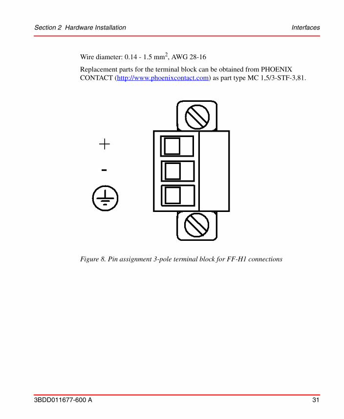
FF H1 Fieldbus Connection
With 3-pole terminal blocks, up to 4 separate fieldbus links can be connected. The FF-H1 interfaces comply with type 114 of the FF physical layer profile, which is characterized by
• standard power signaling and voltage mode
• separately powered operation (galvanically isolated)
• no intrinsic safety
The fieldbus cables +/- can be interchanged.
3 RD+
4 Not used
5 Not used
6 RD-
7 Not used
8 Not used
Figure 7. Schematic representation of the 10/100 Mbit/s Ethernet port
Table 3. Pin assignment of the 10/100 Mbit/s port
Section 2 Hardware Installation Interfaces
3BDD011677-600 A 31
Wire diameter: 0.14 - 1.5 mm2, AWG 28-16
Replacement parts for the terminal block can be obtained from PHOENIX CONTACT (http://www.phoenixcontact.com) as part type MC 1,5/3-STF-3,81.
Figure 8. Pin assignment 3-pole terminal block for FF-H1 connections

Display Elements Section 2 Hardware Installation
32 3BDD011677-600 A
Display Elements
On the front of the linking device there are four LEDs (P - Power Supply, HSE - Ethernet Port, F - Error Status, R - Ready) indicating the device status and another four LEDs (1, 2, 3, 4) indicating the statuses of the four H1 links.
Table 4 shows the symbols used in this document for the various indications of the display elements (LED block).
Table 4. Indication of Display Elements
Symbol Indication of Display Element
Off
red Permanent red
yellow Permanent yellow
green Permanent green
red Flashing red
yellow Flashing yellow
green Flashing green
green Flashing green, slow (0.5 Hz)
green Flashing green, fast (5 Hz)
Section 2 Hardware Installation Display Elements
3BDD011677-600 A 33
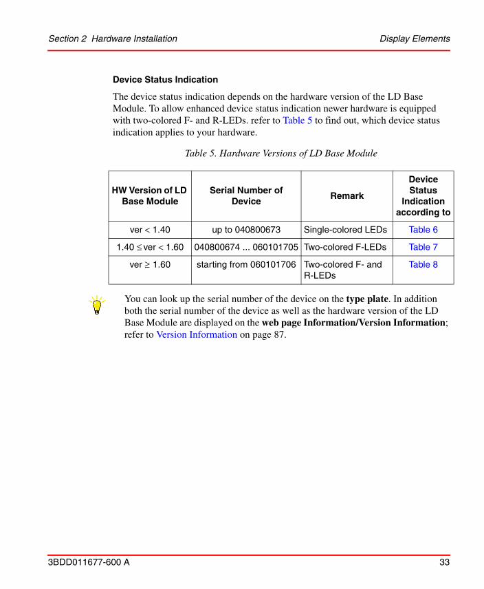
Device Status Indication
The device status indication depends on the hardware version of the LD Base Module. To allow enhanced device status indication newer hardware is equipped with two-colored F- and R-LEDs. refer to Table 5 to find out, which device status indication applies to your hardware.
Table 5. Hardware Versions of LD Base Module
HW Version of LD Base Module
Serial Number of Device
Remark
Device Status
Indication according to
ver < 1.40 up to 040800673 Single-colored LEDs Table 6
1.40 ≤ ver < 1.60 040800674 ... 060101705 Two-colored F-LEDs Table 7
ver ≥ 1.60 starting from 060101706 Two-colored F- and R-LEDs
Table 8
You can look up the serial number of the device on the type plate. In addition both the serial number of the device as well as the hardware version of the LD Base Module are displayed on the web page Information/Version Information; refer to Version Information on page 87.
Display Elements Section 2 Hardware Installation
34 3BDD011677-600 A
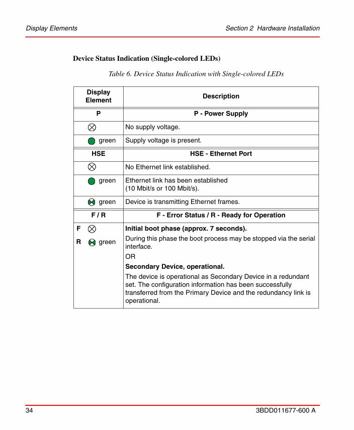
Device Status Indication (Single-colored LEDs)
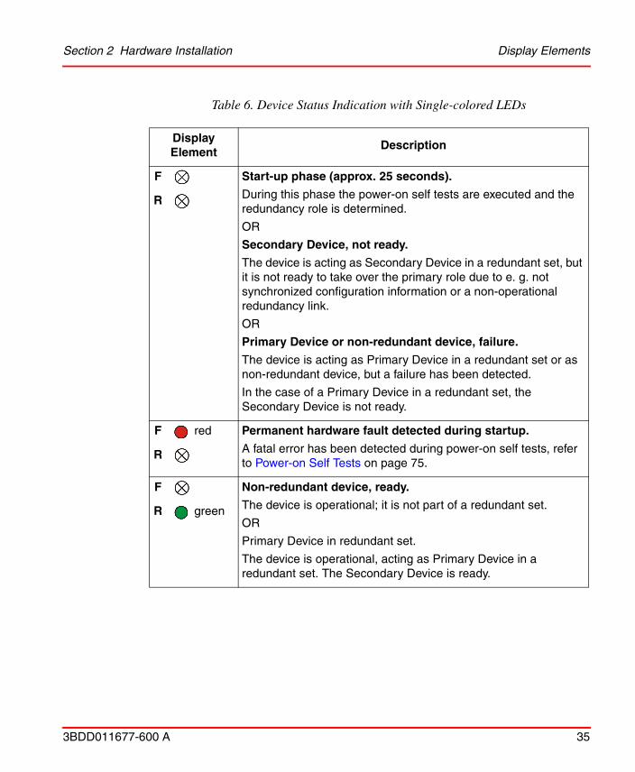
Table 6. Device Status Indication with Single-colored LEDs
Display Element
Description
P P - Power Supply
No supply voltage.
green Supply voltage is present.
HSE HSE - Ethernet Port
No Ethernet link established.
green Ethernet link has been established(10 Mbit/s or 100 Mbit/s).
green Device is transmitting Ethernet frames.
F / R F - Error Status / R - Ready for Operation
F Initial boot phase (approx. 7 seconds).
During this phase the boot process may be stopped via the serial interface.
OR
Secondary Device, operational.
The device is operational as Secondary Device in a redundant set. The configuration information has been successfully transferred from the Primary Device and the redundancy link is operational.
R green
Section 2 Hardware Installation Display Elements
3BDD011677-600 A 35
F Start-up phase (approx. 25 seconds).
During this phase the power-on self tests are executed and the redundancy role is determined.
OR
Secondary Device, not ready.
The device is acting as Secondary Device in a redundant set, but it is not ready to take over the primary role due to e. g. not synchronized configuration information or a non-operational redundancy link.
OR
Primary Device or non-redundant device, failure.
The device is acting as Primary Device in a redundant set or as non-redundant device, but a failure has been detected.
In the case of a Primary Device in a redundant set, the Secondary Device is not ready.
R
F red Permanent hardware fault detected during startup.
A fatal error has been detected during power-on self tests, refer to Power-on Self Tests on page 75.
R
F Non-redundant device, ready.
The device is operational; it is not part of a redundant set.
OR
Primary Device in redundant set.
The device is operational, acting as Primary Device in a redundant set. The Secondary Device is ready.
R green
Table 6. Device Status Indication with Single-colored LEDs
Display Element
Description
Display Elements Section 2 Hardware Installation
36 3BDD011677-600 A
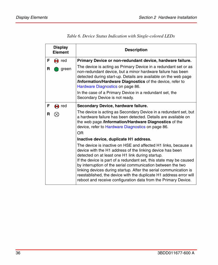
F red Primary Device or non-redundant device, hardware failure.
The device is acting as Primary Device in a redundant set or as non-redundant device, but a minor hardware failure has been detected during start-up. Details are available on the web page /Information/Hardware Diagnostics of the device, refer to Hardware Diagnostics on page 86.
In the case of a Primary Device in a redundant set, the Secondary Device is not ready.
R green
F red Secondary Device, hardware failure.
The device is acting as Secondary Device in a redundant set, but a hardware failure has been detected. Details are available on the web page /Information/Hardware Diagnostics of the device, refer to Hardware Diagnostics on page 86.
OR
Inactive device, duplicate H1 address.
The device is inactive on HSE and affected H1 links, because a device with the H1 address of the linking device has been detected on at least one H1 link during startup.If the device is part of a redundant set, this state may be caused by interruption of the serial communication between the two linking devices during startup. After the serial communication is reestablished, the device with the duplicate H1 address error will reboot and receive configuration data from the Primary Device.
R
Table 6. Device Status Indication with Single-colored LEDs
Display Element
Description
Section 2 Hardware Installation Display Elements
3BDD011677-600 A 37
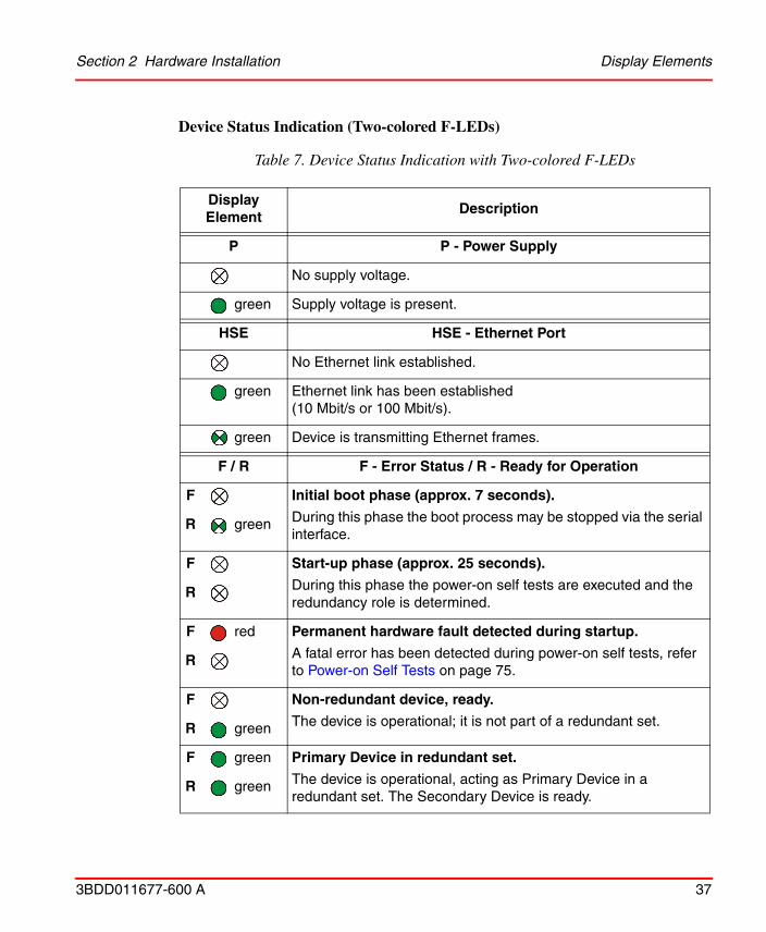
Device Status Indication (Two-colored F-LEDs)
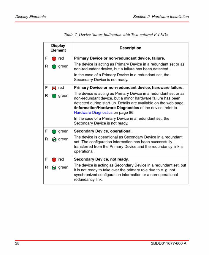
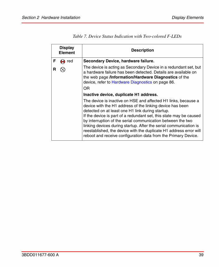
Table 7. Device Status Indication with Two-colored F-LEDs
Display Element
Description
P P - Power Supply
No supply voltage.
green Supply voltage is present.
HSE HSE - Ethernet Port
No Ethernet link established.
green Ethernet link has been established(10 Mbit/s or 100 Mbit/s).
green Device is transmitting Ethernet frames.
F / R F - Error Status / R - Ready for Operation
F Initial boot phase (approx. 7 seconds).
During this phase the boot process may be stopped via the serial interface.
R green
F Start-up phase (approx. 25 seconds).
During this phase the power-on self tests are executed and the redundancy role is determined.
R
F red Permanent hardware fault detected during startup.
A fatal error has been detected during power-on self tests, refer to Power-on Self Tests on page 75.
R
F Non-redundant device, ready.
The device is operational; it is not part of a redundant set.R green
F green Primary Device in redundant set.
The device is operational, acting as Primary Device in a redundant set. The Secondary Device is ready.
R green
Display Elements Section 2 Hardware Installation
38 3BDD011677-600 A
F red Primary Device or non-redundant device, failure.
The device is acting as Primary Device in a redundant set or as non-redundant device, but a failure has been detected.
In the case of a Primary Device in a redundant set, the Secondary Device is not ready.
R green
F red Primary Device or non-redundant device, hardware failure.
The device is acting as Primary Device in a redundant set or as non-redundant device, but a minor hardware failure has been detected during start-up. Details are available on the web page /Information/Hardware Diagnostics of the device, refer to Hardware Diagnostics on page 86.
In the case of a Primary Device in a redundant set, the Secondary Device is not ready.
R green
F green Secondary Device, operational.
The device is operational as Secondary Device in a redundant set. The configuration information has been successfully transferred from the Primary Device and the redundancy link is operational.
R green
F red Secondary Device, not ready.
The device is acting as Secondary Device in a redundant set, but it is not ready to take over the primary role due to e. g. not synchronized configuration information or a non-operational redundancy link.
R green
Table 7. Device Status Indication with Two-colored F-LEDs
Display Element
Description
Section 2 Hardware Installation Display Elements
3BDD011677-600 A 39
F red Secondary Device, hardware failure.
The device is acting as Secondary Device in a redundant set, but a hardware failure has been detected. Details are available on the web page /Information/Hardware Diagnostics of the device, refer to Hardware Diagnostics on page 86.
OR
Inactive device, duplicate H1 address.
The device is inactive on HSE and affected H1 links, because a device with the H1 address of the linking device has been detected on at least one H1 link during startup.If the device is part of a redundant set, this state may be caused by interruption of the serial communication between the two linking devices during startup. After the serial communication is reestablished, the device with the duplicate H1 address error will reboot and receive configuration data from the Primary Device.
R
Table 7. Device Status Indication with Two-colored F-LEDs
Display Element
Description

Display Elements Section 2 Hardware Installation
40 3BDD011677-600 A
Device Status Indication (Two-colored F- and R-LEDs)
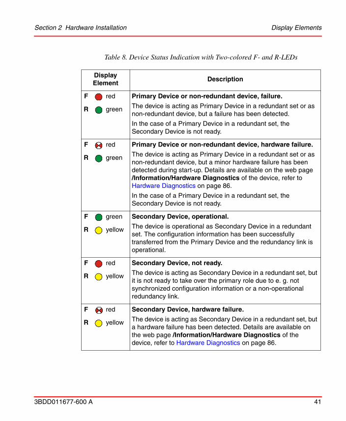
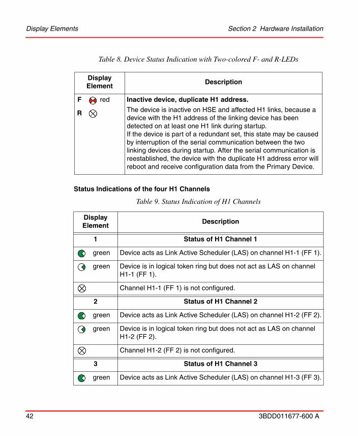
Table 8. Device Status Indication with Two-colored F- and R-LEDs
Display Element
Description
P P - Power Supply
No supply voltage.
green Supply voltage is present.
HSE HSE - Ethernet Port
No Ethernet link established.
green Ethernet link has been established(10 Mbit/s or 100 Mbit/s).
green Device is transmitting Ethernet frames.
F / R F - Error Status / R - Ready for Operation
F Initial boot phase (approx. 7 seconds).
During this phase the boot process may be stopped via the serial interface.
R green
F Start-up phase (approx. 25 seconds).
During this phase the power-on self tests are executed and the redundancy role is determined.
R
F red Permanent hardware fault detected during startup.
A fatal error has been detected during power-on self tests, refer to Power-on Self Tests on page 75.
R
F Non-redundant device, ready.
The device is operational; it is not part of a redundant set.R green
F green Primary Device in redundant set.
The device is operational, acting as Primary Device in a redundant set. The Secondary Device is ready.
R green
Section 2 Hardware Installation Display Elements
3BDD011677-600 A 41
F red Primary Device or non-redundant device, failure.
The device is acting as Primary Device in a redundant set or as non-redundant device, but a failure has been detected.
In the case of a Primary Device in a redundant set, the Secondary Device is not ready.
R green
F red Primary Device or non-redundant device, hardware failure.
The device is acting as Primary Device in a redundant set or as non-redundant device, but a minor hardware failure has been detected during start-up. Details are available on the web page /Information/Hardware Diagnostics of the device, refer to Hardware Diagnostics on page 86.
In the case of a Primary Device in a redundant set, the Secondary Device is not ready.
R green
F green Secondary Device, operational.
The device is operational as Secondary Device in a redundant set. The configuration information has been successfully transferred from the Primary Device and the redundancy link is operational.
R yellow
F red Secondary Device, not ready.
The device is acting as Secondary Device in a redundant set, but it is not ready to take over the primary role due to e. g. not synchronized configuration information or a non-operational redundancy link.
R yellow
F red Secondary Device, hardware failure.
The device is acting as Secondary Device in a redundant set, but a hardware failure has been detected. Details are available on the web page /Information/Hardware Diagnostics of the device, refer to Hardware Diagnostics on page 86.
R yellow
Table 8. Device Status Indication with Two-colored F- and R-LEDs
Display Element
Description
Display Elements Section 2 Hardware Installation
42 3BDD011677-600 A
Status Indications of the four H1 Channels
F red Inactive device, duplicate H1 address.
The device is inactive on HSE and affected H1 links, because a device with the H1 address of the linking device has been detected on at least one H1 link during startup.If the device is part of a redundant set, this state may be caused by interruption of the serial communication between the two linking devices during startup. After the serial communication is reestablished, the device with the duplicate H1 address error will reboot and receive configuration data from the Primary Device.
R
Table 9. Status Indication of H1 Channels
Display Element
Description
1 Status of H1 Channel 1
green Device acts as Link Active Scheduler (LAS) on channel H1-1 (FF 1).
green Device is in logical token ring but does not act as LAS on channel H1-1 (FF 1).
Channel H1-1 (FF 1) is not configured.
2 Status of H1 Channel 2
green Device acts as Link Active Scheduler (LAS) on channel H1-2 (FF 2).
green Device is in logical token ring but does not act as LAS on channel H1-2 (FF 2).
Channel H1-2 (FF 2) is not configured.
3 Status of H1 Channel 3
green Device acts as Link Active Scheduler (LAS) on channel H1-3 (FF 3).
Table 8. Device Status Indication with Two-colored F- and R-LEDs
Display Element
Description

Section 2 Hardware Installation Display Elements
3BDD011677-600 A 43
green Device is in logical token ring but does not act as LAS on channel H1-3 (FF 3).
Channel H1-3 (FF 3) is not configured.
4 Status of H1 Channel 4
green Device acts as Link Active Scheduler (LAS) on channel H1-4 (FF 4).
green Device is in logical token ring but does not act as LAS on channel H1-4 (FF 4).
Channel H1-4 (FF 4) is not configured.
Table 9. Status Indication of H1 Channels
Display Element
Description

Commissioning the Hardware Section 2 Hardware Installation
44 3BDD011677-600 A
Commissioning the HardwareFor commissioning the hardware, perform the following steps:
1. Connect the H1 links to the terminal blocks of the H1 interfaces. Since the linking device does not provide power to the H1 links, a power supply, a power conditioner and a bus termination is required for each H1 link.When using a redundant set of two linking devices, make sure to connect each H1 link to the same channel (FF 1.. FF 4) on both linking devices.
2. Connect the linking device to an Ethernet switch or hub.
3. When using a redundant set of two linking devices, connect both serial ports by means of an RS-232 null modem cable (Article No: 3BDH000281R1).
4. Connect the linking device to a 24 V DC power supply. Use different or redundant power supplies for redundant linking devices.
5. Turn on the power supply. The boot process takes approx. 50 seconds. For indication of proper operation of a linking device acting in non-redundant mode or as Primary Device in redundant mode, refer to Display Elements on page 32.
When using a redundant set of two linking devices, the device which is powered first will operate as Primary Device. If both devices are powered at the same time, the one with the lower IP address will operate as Primary Device.
If the two linking devices forming a redundant set are powered while the serial link is missing, both devices will behave like independent, non-redundant Primary Devices. If they operated in redundant mode before and therefore have identical configuration information, both will use the same H1 node addresses, which will cause problems on the H1 links. In this case, remove the power, install the serial link and apply the power again.
In a redundant set of linking devices, removing the power supply, the Ethernet cable or the RS-232 cable from the Primary Device causes a redundancy change-over. Before doing so, make sure that the Secondary Device is operational (and not still booting due to a prior change-over). Otherwise the system breaks down or the configuration information might get lost. Therefore wait at least one minute between such checks.

Section 2 Hardware InstallationReplacing a Defective Linking Device in a Redundant Set of Linking
3BDD011677-600 A 45
Replacing a Defective Linking Device in a Redundant Set of Linking Devices
For replacing a defective linking device in a redundant set of linking devices, perform the following steps:
1. Identify the defective linking device, refer to Display Elements on page 32.
2. Remove the power terminal block from the linking device.
3. Remove the RS-232 cable (redundancy link) and the Ethernet cable.
4. If not indicated on the cable, make a note to which channel each H1 link is connected. Then remove the H1 terminal blocks.
5. Make sure that the new linking device has the same IP configuration (IP address and subnet mask) as the replaced defective device, see Network Configuration on page 61.
6. Replace the defective linking device.
7. Plug in the H1 terminal blocks. Make sure to use the same allocation as before
8. Connect the Ethernet cable and the RS-232 cable.
9. Plug in the power terminal block. The boot process and the download of the configuration information take about 1 minute. For indication of proper operation as a Secondary Device, refer to Display Elements on page 32.
Make sure not to permute the H1 terminal blocks! An accidental permutation of the H1 link connections at the secondary linking device will not be detected right away. On application level detection will not be possible before a redundancy switch-over takes place or the live lists of primary and secondary linking device are being compared manually.
Make sure that the RS-232 cable is connected before plugging in the power terminal block.If the replaced linking device is powered while the serial link is missing, it will behave like an independent, non-redundant Primary Device. If in this case the linking device has a valid (possibly unknown) configuration, it might use H1 node addresses which are already in use on the H1 links. This will disturb or interrupt communication and application processing on the H1 links.
Adding a Second Linking Device to form a Redundant Set of Linking Devices Section 2 Hardware
46 3BDD011677-600 A
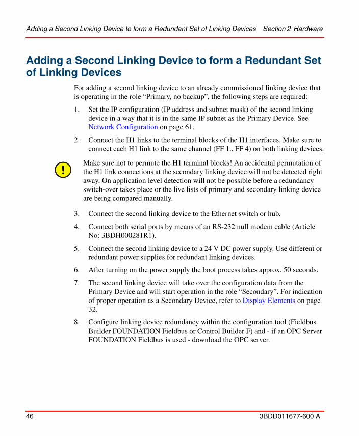
Adding a Second Linking Device to form a Redundant Set of Linking Devices
For adding a second linking device to an already commissioned linking device that is operating in the role “Primary, no backup”, the following steps are required:
1. Set the IP configuration (IP address and subnet mask) of the second linking device in a way that it is in the same IP subnet as the Primary Device. See Network Configuration on page 61.
2. Connect the H1 links to the terminal blocks of the H1 interfaces. Make sure to connect each H1 link to the same channel (FF 1.. FF 4) on both linking devices.
3. Connect the second linking device to the Ethernet switch or hub.
4. Connect both serial ports by means of an RS-232 null modem cable (Article No: 3BDH000281R1).
5. Connect the second linking device to a 24 V DC power supply. Use different or redundant power supplies for redundant linking devices.
6. After turning on the power supply the boot process takes approx. 50 seconds.
7. The second linking device will take over the configuration data from the Primary Device and will start operation in the role “Secondary”. For indication of proper operation as a Secondary Device, refer to Display Elements on page 32.
8. Configure linking device redundancy within the configuration tool (Fieldbus Builder FOUNDATION Fieldbus or Control Builder F) and - if an OPC Server FOUNDATION Fieldbus is used - download the OPC server.
Make sure not to permute the H1 terminal blocks! An accidental permutation of the H1 link connections at the secondary linking device will not be detected right away. On application level detection will not be possible before a redundancy switch-over takes place or the live lists of primary and secondary linking device are being compared manually.

Section 3 Configuration Communication Settings
3BDD011677-600 A 47
Section 3 Configuration
Communication SettingsAlthough the linking device is delivered with a pre-configured IP address (192.168.1.20), it must be assigned an IP address from your LAN address range.
Furthermore, subnet mask and gateway IP address must be set accordingly. This information is referred to as IP configuration.
Table 10 shows the pre-configured IP settings of the linking device.
The IP configuration can be changed using one of the following methods:
Table 10. Pre-configured IP Settings
Parameter Name Pre-configured value Remark
Host Name LD 800HSE not used; you may leave this unchanged or empty
IP Address 192.168.1.20 mandatory
Subnet Mask 255.255.255.0 mandatory
Maintenance IP Address
192.168.1.21 recommended; for details see Network Configuration on page 61
Broadcast Address 192.168.1.255 not used; it is automatically adapted to the configured IP address and subnet mask
Default Gateway 192.168.1.21 it is not necessary to config-ure a default gateway, if the host and the linking device share the same network

Communication Settings Section 3 Configuration
48 3BDD011677-600 A
• via Ethernet by means of a web browser (HTTP protocol, recommended)
• via the serial port (RS-232) by means of a terminal program
Each LD 800HSE sends messages to IP address 224.0.0.33 cyclically every 15 seconds.
In case the IP configuration of LD 800HSE is not known and a serial connection cable is not available, you could capture its ethernet traffic with a network monitoring tool (e.g. Wireshark) for approx. 30 seconds to find its IP address as the IP source address of these cyclical messages!
Section 3 Configuration Communication Settings
3BDD011677-600 A 49
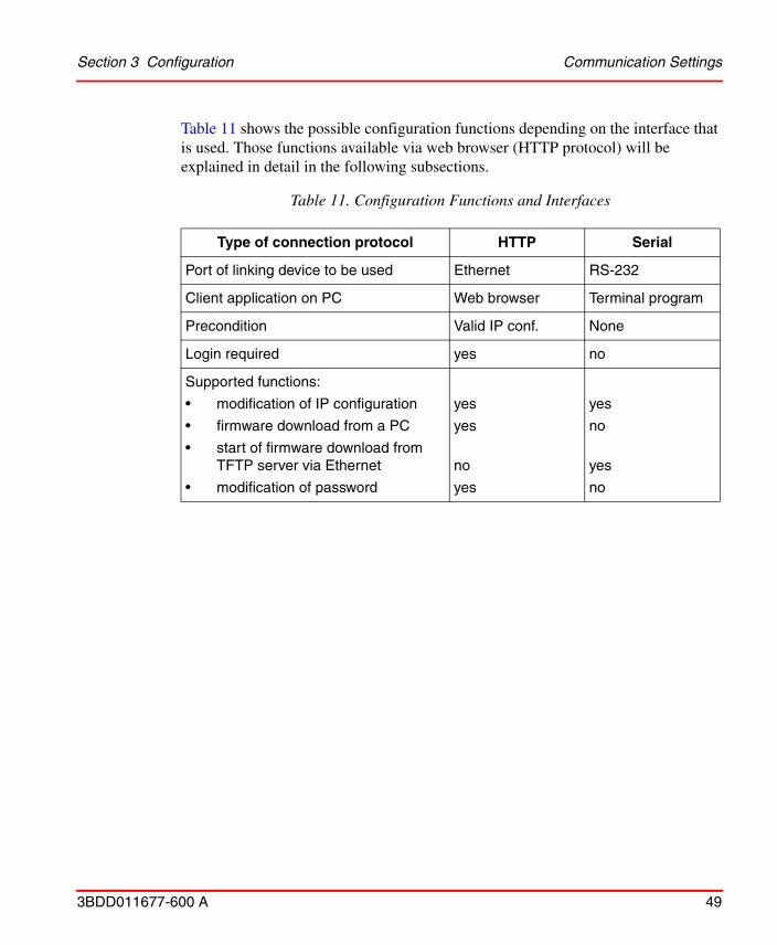
Table 11 shows the possible configuration functions depending on the interface that is used. Those functions available via web browser (HTTP protocol) will be explained in detail in the following subsections.
Table 11. Configuration Functions and Interfaces
Type of connection protocol HTTP Serial
Port of linking device to be used Ethernet RS-232
Client application on PC Web browser Terminal program
Precondition Valid IP conf. None
Login required yes no
Supported functions:
• modification of IP configuration
• firmware download from a PC
• start of firmware download from TFTP server via Ethernet
• modification of password
yes
yes
no
yes
yes
no
yes
no

Setting Up an IP Connection between PC and Linking Device Section 3 Configuration
50 3BDD011677-600 A
Setting Up an IP Connection between PC and Linking Device
The linking device is delivered with the pre-configured IP address 192.168.1.20.
Connect the linking device to your PC. For a direct connection, a cross-linking cable must be used. This is not necessary if a hub is interconnected.
In the following, establishment of a connection to your linking device by TCP/IP will be explained. Such a connection makes it possible to change the pre-configured IP address of the linking device. No auxiliaries, such as serial cables, are necessary with this method.
Step1: You will need the following information which can be obtained from your network administrator:
• IP address for the linking device
• Subnet mask
• IP address of the default gateway
• IP address of maintenance server
Before connecting the linking device to your LAN network, make sure that its IP address is not used by another network station.
It is not necessary to configure a default gateway if the PC and the linking device share the same network.
The maintenance server is required to update the linking device firmware via Ethernet. The maintenance server is a TFTP server (Tiny File Transfer Protocol) that contains an image of the flash memory content of the linking device. It is also possible to perform a firmware update via web browser from a PC. In that case it is not necessary to install a maintenance server and to specify its address in the linking device.

Section 3 Configuration Setting Up an IP Connection between PC and Linking Device
3BDD011677-600 A 51
Step 2: Configure your PC in such a way that you have access to the network 192.168.1.0. For this purpose, you may have to assign your PC a second IP address (e.g. IP address = 192.168.1.100, net mask = 255.255.255.0, broadcast = 192.168.1.255), refer to Assignment of a Second (Local) IP Address on page 52
Step 3: Try to ping the linking device. Open a DOS box and enter the following command: ‘ping 192.168.1.20‘. The linking device must respond.
If it does not respond you should proceed as follows:
• Check whether the linking device is correctly connected to the LAN and whether it is switched on.
• Check also whether your PC is correctly connected to the LAN by a cable.
• Check whether the PC has been configured with a valid IP address from the subnet 192.168.1.0. Try to ping the second (local) IP address of your PC (in the example, 192.168.1.100). If the local host does not respond, the second IP address has not been initialized correctly.
Step 4: If you have access to the linking device from your PC, you can change its network configuration with a web browser, refer to Firmware Update on page 65
To assign a new IP address to your PC, you must have administrator rights.

Setting Up an IP Connection between PC and Linking Device Section 3 Configuration
52 3BDD011677-600 A
Assignment of a Second (Local) IP Address
This subsection describes how to assign a second IP address to a PC running on the latest supporting operation system. For other operating systems, refer to the corresponding instructions manual or to the online help of the operating system used.
• Open Control Panel
• Double-click Network Connections.
Figure 9. Network Connections

Section 3 Configuration Setting Up an IP Connection between PC and Linking Device
3BDD011677-600 A 53
• Right-click Local Area Connection and then click Properties.
Figure 10. Local Area Connection Properties
Setting Up an IP Connection between PC and Linking Device Section 3 Configuration
54 3BDD011677-600 A
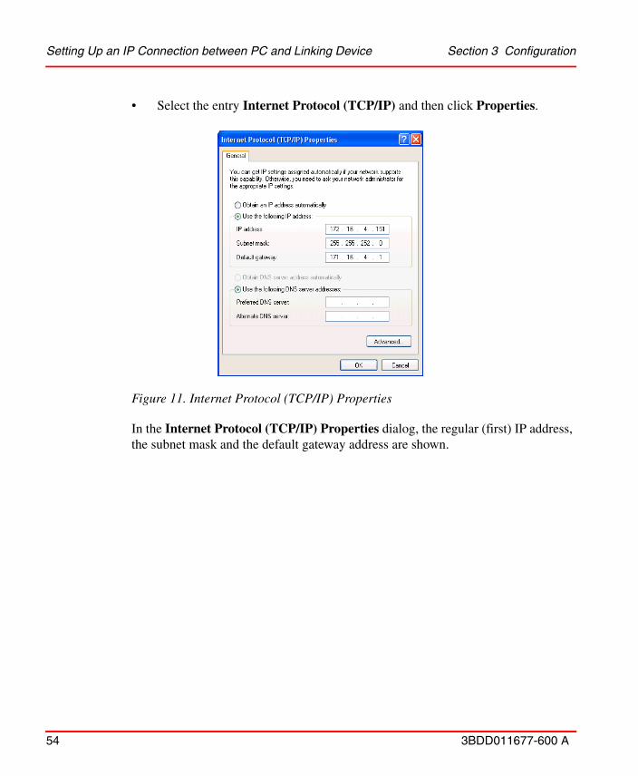
• Select the entry Internet Protocol (TCP/IP) and then click Properties.
In the Internet Protocol (TCP/IP) Properties dialog, the regular (first) IP address, the subnet mask and the default gateway address are shown.
Figure 11. Internet Protocol (TCP/IP) Properties
Section 3 Configuration Setting Up an IP Connection between PC and Linking Device
3BDD011677-600 A 55
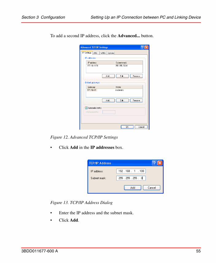
To add a second IP address, click the Advanced... button.
• Click Add in the IP addresses box.
• Enter the IP address and the subnet mask.
• Click Add.
Figure 12. Advanced TCP/IP Settings
Figure 13. TCP/IP Address Dialog
System Settings Section 3 Configuration
56 3BDD011677-600 A
• Confirm all windows with OK till you get back to the Local Area Connection Properties window.
• Press the Close button.
System SettingsAfter an IP connection between PC and linking device has been set up as described in the subsection Setting Up an IP Connection between PC and Linking Device on page 50, you may access the linking device from your PC by means of a web browser that supports JavaScript (e. g. Microsoft Internet Explorer).
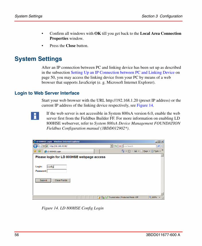
Login to Web Server Interface
Start your web browser with the URL http://192.168.1.20 (preset IP address) or the current IP address of the linking device respectively, see Figure 14.
If the web server is not accessible in System 800xA version 6.0, enable the web server first from the Fieldbus Builder FF. For more information on enabling LD 800HSE webserver, refer to System 800xA Device Management FOUNDATION Fieldbus Configuration manual (3BDD012902*).
Figure 14. LD 800HSE Config Login

Section 3 Configuration Login to Web Server Interface
3BDD011677-600 A 57
Table 12 explains the list of users who can login to the linking device, based the logged in user the Linking Device Web Server page is displayed.
Table 12. LD 800HSE Users
User Default Password Role
operat vwit Operation user
config(1)
(1) For user who is logged in as Config, the default password is an empty string.
Configuration user with permission to load firmware etc.
diag Suppmfp Diagnostics user with access to diagnosis informations
The default passwords of the users must be replaced with passwords that conforms with your organization's security policy at the first possible opportunity. Failure to replace the default password makes the system susceptible to unauthorized access.
Refer to the Password Security topic in System 800xA Administration and Security (3BSE037410*) for recommendations on establishing a password security scheme.
Login to Web Server Interface Section 3 Configuration
58 3BDD011677-600 A
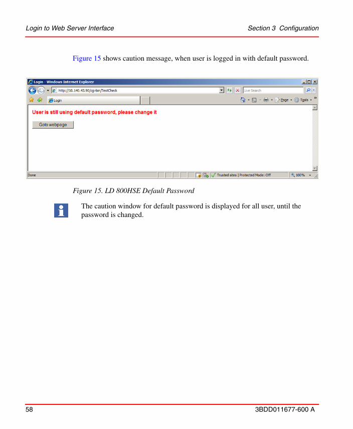
Figure 15 shows caution message, when user is logged in with default password.
Figure 15. LD 800HSE Default Password
The caution window for default password is displayed for all user, until the password is changed.
Section 3 Configuration Login to Web Server Interface
3BDD011677-600 A 59
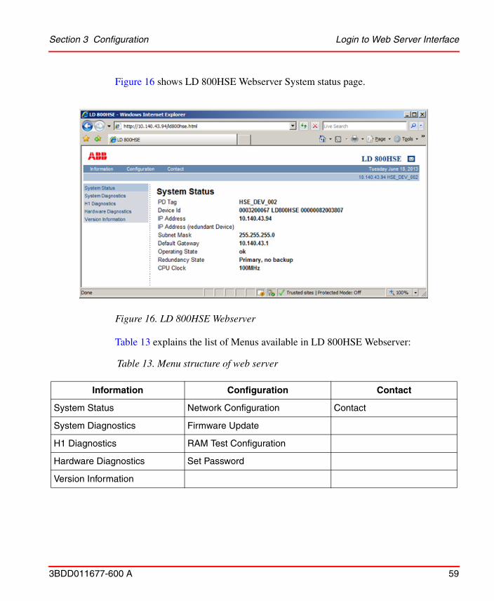
Figure 16 shows LD 800HSE Webserver System status page.
Table 13 explains the list of Menus available in LD 800HSE Webserver:
Figure 16. LD 800HSE Webserver
Table 13. Menu structure of web server
Information Configuration Contact
System Status Network Configuration Contact
System Diagnostics Firmware Update
H1 Diagnostics RAM Test Configuration
Hardware Diagnostics Set Password
Version Information

Login to Web Server Interface Section 3 Configuration
60 3BDD011677-600 A
The sub menus under Information category display current values read from the device and are not password protected. These pages are explained in the subsection, Built-in Web Server on page 76
The sub menus under Configuration category allow modifying of configuration parameters or performing a firmware update. These pages are protected by a password.
Modifying of configuration parameter is allowed only for the user who is logged in as config. The following sub topics describes the list of sub menus under Configuration category.
The Contact page provides useful information about the product or technical support or provide feedback about the product.
Section 3 Configuration Login to Web Server Interface
3BDD011677-600 A 61
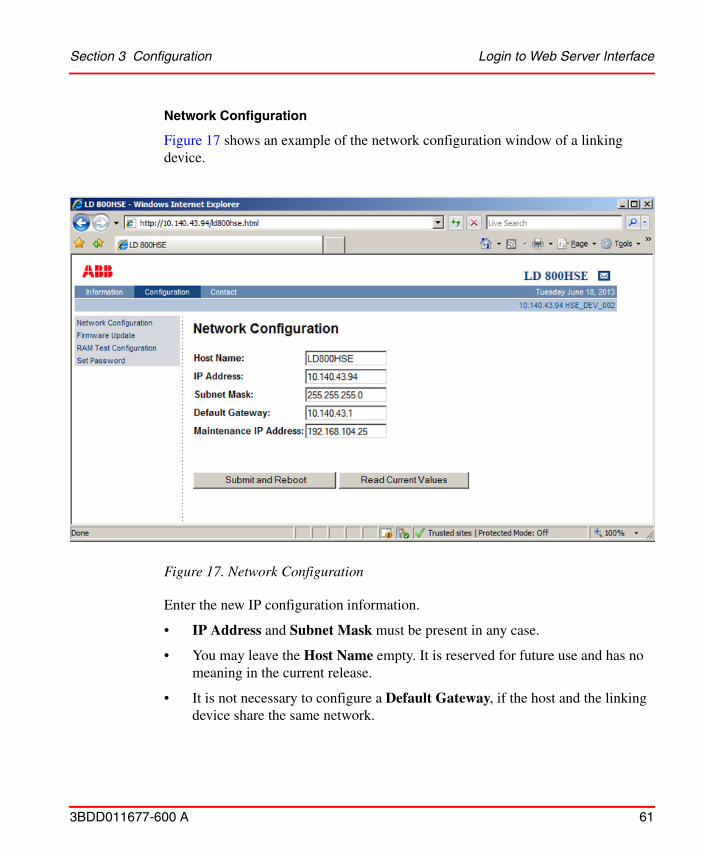
Network Configuration
Figure 17 shows an example of the network configuration window of a linking device.
Enter the new IP configuration information.
• IP Address and Subnet Mask must be present in any case.
• You may leave the Host Name empty. It is reserved for future use and has no meaning in the current release.
• It is not necessary to configure a Default Gateway, if the host and the linking device share the same network.
Figure 17. Network Configuration

Login to Web Server Interface Section 3 Configuration
62 3BDD011677-600 A
• The Maintenance IP Address is required to download the linking device firmware from a maintenance server. The maintenance server is a TFTP server (Tiny File Transfer Protocol) that contains an image of the flash memory content of the linking device and a batch file. It is also possible to download a new firmware from your PC by means of a web browser. In that case it is not necessary to install a maintenance server and to specify its address.
When the entries are complete, click the Submit and Reboot button.
The input values will be checked for consistency. If the input values are not consistent, the linking device will propose consistent values. You can use the proposed values by clicking Yes or keep at the values you entered by selecting No, see Figure 18.

Section 3 Configuration Login to Web Server Interface
3BDD011677-600 A 63
The linking device will be rebooted after a few seconds and the new values will be accepted, see Figure 19.
Figure 18. Window after incorrect parameters have been entered
If you change the IP address of the linking device, the IP connection between PC and linking device will be lost. You have to use the new IP address to re-establish web access to the linking device.
If an inconsistent network configuration is used, it might be impossible to connect to the linking device again. In this case, only the serial interface (RS-232) can be used to set again a valid IP configuration (see Plant Configuration and Commissioning on page 72).
Login to Web Server Interface Section 3 Configuration
64 3BDD011677-600 A
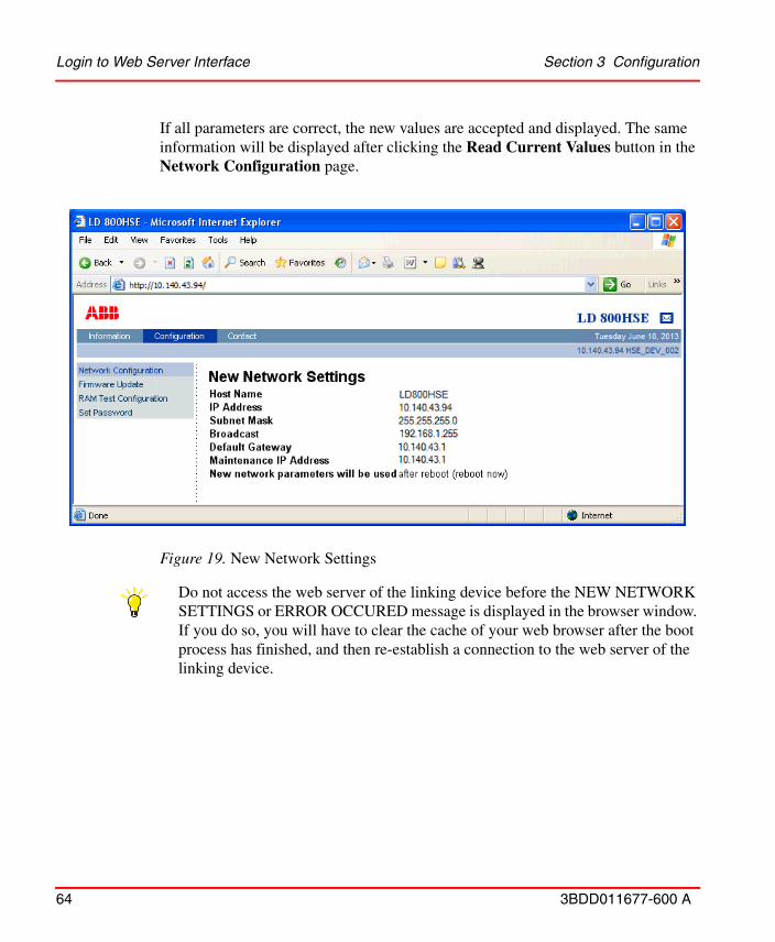
If all parameters are correct, the new values are accepted and displayed. The same information will be displayed after clicking the Read Current Values button in the Network Configuration page.
Figure 19. New Network Settings
Do not access the web server of the linking device before the NEW NETWORK SETTINGS or ERROR OCCURED message is displayed in the browser window. If you do so, you will have to clear the cache of your web browser after the boot process has finished, and then re-establish a connection to the web server of the linking device.
Section 3 Configuration Login to Web Server Interface
3BDD011677-600 A 65
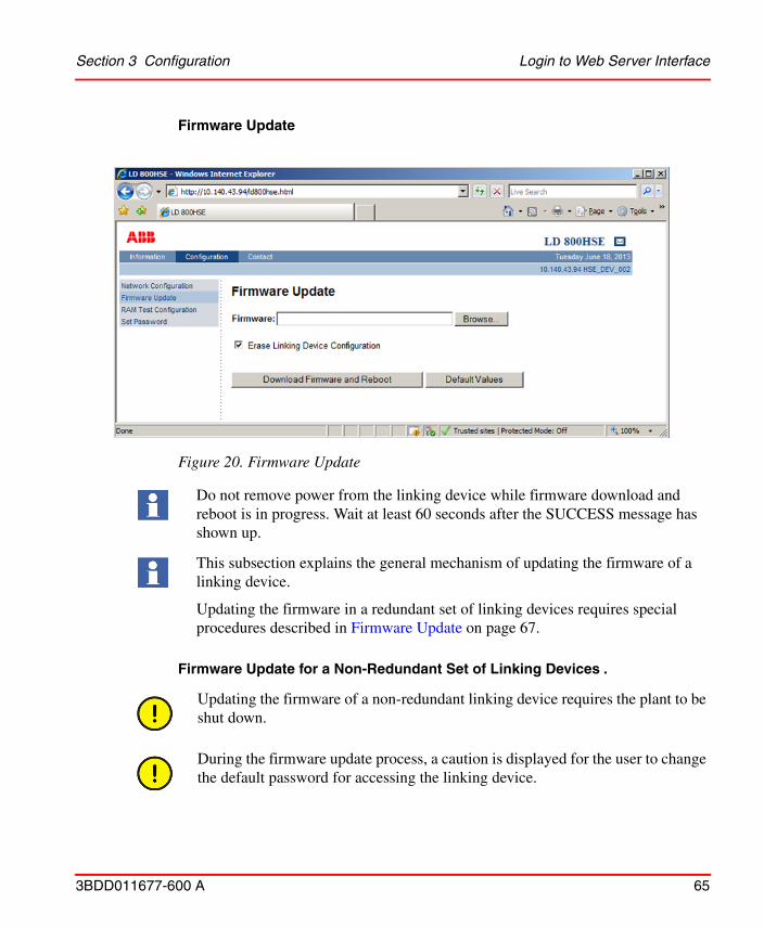
Firmware Update
Firmware Update for a Non-Redundant Set of Linking Devices .
Figure 20. Firmware Update
Do not remove power from the linking device while firmware download and reboot is in progress. Wait at least 60 seconds after the SUCCESS message has shown up.
This subsection explains the general mechanism of updating the firmware of a linking device.
Updating the firmware in a redundant set of linking devices requires special procedures described in Firmware Update on page 67.
Updating the firmware of a non-redundant linking device requires the plant to be shut down.
During the firmware update process, a caution is displayed for the user to change the default password for accessing the linking device.
Login to Web Server Interface Section 3 Configuration
66 3BDD011677-600 A
1. Click the Browse button on the Firmware Update page to open a file selector box.
2. Select the firmware file to be downloaded.
3. It is recommended to erase the configuration part of the flash memory by checking Erase Linking Device Configuration. This will clear the FF configuration information (plant configuration), but the IP configuration will not be changed.
4. Click Download Firmware and Reboot to start the download process. Firmware download and flash memory update take between one and two minutes. You can observe the progress of the update process in the browser window.
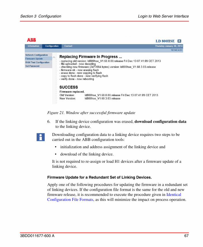
5. The successful completion of the update process is indicated by the message SUCCESS, see Figure 21.
If you erase the linking device configuration, the password will be reset to its default value, which is an empty string. If this occurs, the password must be changed from the default value.
During Reboot, the IP connection between PC and linking device will be lost.
After the SUCCESS message is displayed, do not power down the linking device before the H1 link LEDs have lit up at least once OR or at least 60 seconds have elapsed.
Do not access the web server of the linking device before the SUCCESS message is displayed in the browser window. If you do so, you will have to clear the cache of your web browser after the boot process has finished, and then re-establish a connection to the web server of the linking device.
Section 3 Configuration Login to Web Server Interface
3BDD011677-600 A 67
6. If the linking device configuration was erased, download configuration data to the linking device.
Firmware Update for a Redundant Set of Linking Devices.
Apply one of the following procedures for updating the firmware in a redundant set of linking devices. If the configuration file format is the same for the old and new firmware release, it is recommended to execute the procedure given in Identical Configuration File Formats, as this will minimize the impact on process operation.
Figure 21. Window after successful firmware update
Downloading configuration data to a linking device requires two steps to be carried out in the ABB configuration tools:
• initialization and address assignment of the linking device and
• download of the linking device.
It is not required to re-assign or load H1 devices after a firmware update of a linking device.

Login to Web Server Interface Section 3 Configuration
68 3BDD011677-600 A
In the case of different or unknown configuration file formats execute the steps described in Different or Unknown Configuration File Formats.
Identical Configuration File Formats.
1. Check, which linking device acts as Secondary Device.
2. Update the firmware in the Secondary Device using the web interface, refer to Firmware Update on page 65, but do not download configuration data.
3. After the firmware update is successfully completed, the Secondary Device will boot.
4. Wait until the Secondary Device is fully operational again:
a. H1 LEDs are flashing
OR
b. status of the Secondary Device has recovered to a green check mark again as shown in the HSE Device Instance Object dialog in commissioning mode of Fieldbus Builder FF.
5. Enforce a redundancy switch-over (e. g. by disconnecting the HSE cable at the Primary Device).
6. Update the firmware in the remaining device (Secondary Device after redundancy switch-over) using the web interface.
Refer to the LD 800HSE Compatibility Matrix (3BDS009911) to find out the configuration file format of the firmware releases involved.
The following procedure works only if the configuration file format is the same for the old and new firmware release. The only impact on process operation is that caused by a redundancy switch-over.
For firmware updates from 1.50.1.02 to latest version a manually enforced redundancy switch-over as described in Step 5 is not required. This will happen automatically, when updating the still Primary Device using the web interface in Step 6.
Section 3 Configuration Login to Web Server Interface
3BDD011677-600 A 69
Different or Unknown Configuration File Formats.
1. Update the firmware in either of the devices making up the redundant set, using the web interface, refer to Firmware Update on page 65, but do not download configuration data.
2. Update the firmware in the remaining device using the web interface.
3. Wait until both devices have completed rebooting.
4. Download configuration data to the redundant set of devices.
Updating Firmware from 1.50.1.02 to Latest Version.
For updating linking devices with firmware from 1.50.1.02 to latest version, the normal procedure applies as described in Firmware Update on page 65.
When updating a redundant set of linking devices, follow the procedure of subsection Firmware Update on page 67 as described in the following subsection Identical Configuration File Formats.
The following procedure works regardless of the file formats of the old and new firmware release. As HSE and H1 communication will be stopped for the affected redundant set of linking devices, it is not recommended to apply this procedure to an operating set of devices.
Applying the following procedure for a firmware update on an operating redundant set of linking devices stops all HSE republishing and cyclical communication on all H1 links of that set of linking devices as well as client/server communication to the linking device and the devices on the H1 links. No cyclical or client/server communication on the H1 links of the affected redundant set of linking devices is possible until configuration data has been downloaded to the redundant set of devices.
Downloading configuration data to a linking device requires the following steps to be carried out in the ABB configuration tools:
• initialization and address assignment of the linking device and
• download of the linking device.
It is not required to re-assign or load H1 devices after a firmware update of a linking device.
Login to Web Server Interface Section 3 Configuration
70 3BDD011677-600 A
Updating Firmware from 1.30 to Latest Version.
When updating linking devices with firmware version from 1.30 to latest version, existing configuration files will be accepted. However to ensure comparable configuration it is required to download configuration data after the update.
• When updating a non-redundant linking device, follow the procedure of subsection Firmware Update on page 65 and make sure that the check box Erase Linking Device Configuration is checked.
• When updating a redundant set of linking devices, follow the procedure of subsection Firmware Update on page 67 as described in the following subsection Different or Unknown Configuration File Formats.
Updating Firmware prior to 1.20 to Latest Version.
Updating firmware releases prior to 1.20 to latest version using the web server might not be successful in some cases, due to defects in the update procedure of those early releases. When such problems are encountered, first try to repeat the firmware update. Before repeating, clear the cache of your browser (delete all temporary internet files) to make sure that the linking device is accessed and not just the local cache.
If the update process fails permanently, perform the firmware update using the RS-232 connection and a TFTP server. For detailed information on how to update the firmware using a TFTP server see the User Instructions FOUNDATION Fieldbus Linking Device LD 800HSE.
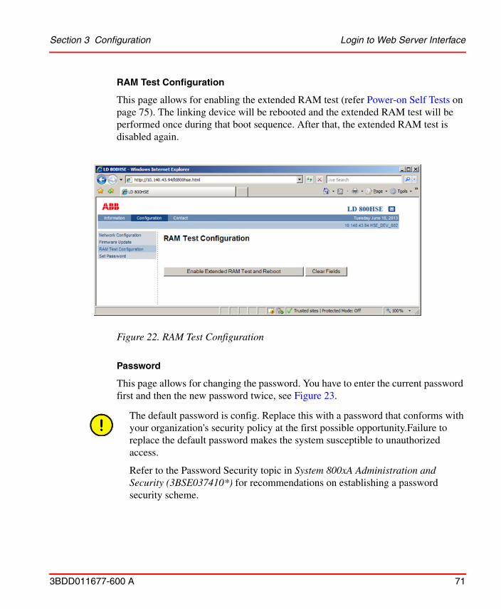
Section 3 Configuration Login to Web Server Interface
3BDD011677-600 A 71
RAM Test Configuration
This page allows for enabling the extended RAM test (refer Power-on Self Tests on page 75). The linking device will be rebooted and the extended RAM test will be performed once during that boot sequence. After that, the extended RAM test is disabled again.
Password
This page allows for changing the password. You have to enter the current password first and then the new password twice, see Figure 23.
Figure 22. RAM Test Configuration
The default password is config. Replace this with a password that conforms with your organization's security policy at the first possible opportunity.Failure to replace the default password makes the system susceptible to unauthorized access.
Refer to the Password Security topic in System 800xA Administration and Security (3BSE037410*) for recommendations on establishing a password security scheme.
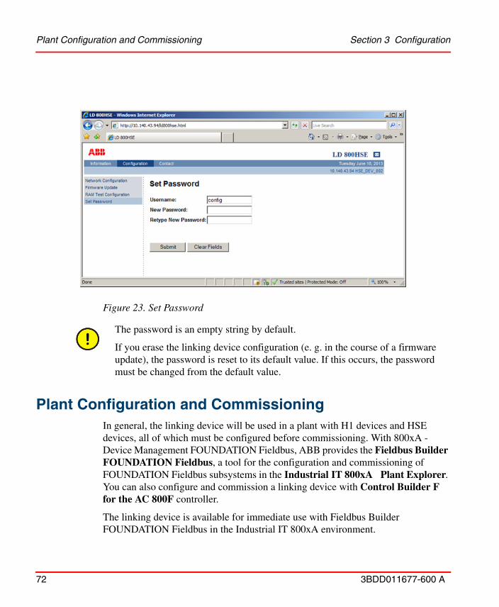
Plant Configuration and Commissioning Section 3 Configuration
72 3BDD011677-600 A
Plant Configuration and CommissioningIn general, the linking device will be used in a plant with H1 devices and HSE devices, all of which must be configured before commissioning. With 800xA - Device Management FOUNDATION Fieldbus, ABB provides the Fieldbus Builder FOUNDATION Fieldbus, a tool for the configuration and commissioning of FOUNDATION Fieldbus subsystems in the Industrial IT 800xA Plant Explorer. You can also configure and commission a linking device with Control Builder F for the AC 800F controller.
The linking device is available for immediate use with Fieldbus Builder FOUNDATION Fieldbus in the Industrial IT 800xA environment.
Figure 23. Set Password
The password is an empty string by default.
If you erase the linking device configuration (e. g. in the course of a firmware update), the password is reset to its default value. If this occurs, the password must be changed from the default value.
Section 3 Configuration Using a Redundant Set of Linking Devices
3BDD011677-600 A 73
To enable Control Builder F to do the configuration and commissioning of linking devices of type LD 800HSE, this HSE device type has to be imported to the engineering tool. For this purpose you will need the capabilities file (a file with the extension .cfh) that is included on the Media CD-ROM LD 800HSE or is available for download in the ABB SolutionsBank.
Prerequisites for doing the plant configuration with Fieldbus Builder FOUNDATION Fieldbus / Control Builder F are
• a valid IP configuration of the linking device as described in Firmware Update on page 65 and
• a physically commissioned linking device according to the commissioning steps listed in Commissioning the Hardware on page 44.
In the Fieldbus Builder FOUNDATION Fieldbus / Control Builder F the IP address set on the linking device has to be entered. It is used for identifying the linking device, and forms the basis for all the connection-based communication with the linking device.
Using a Redundant Set of Linking Devices
In the case of a redundant set of linking devices also the IP address of the second physical linking device has to be entered.
Additional information, firmware, and capabilities files for this product are available in the ABB SolutionsBank. For details refer to Section 2, Hardware Installation.
When the two linking devices forming a redundant set are powered, the serial link must be present. If the serial link is missing while the devices are powered, both devices will behave like independent, non-redundant Primary Devices.

Support for Multi User Engineering Section 3 Configuration
74 3BDD011677-600 A
Support for Multi User Engineering
For System 800xA SV5.1 onwards, LD 800HSE supports multi user engineering. It allows concurrent configuration and commissioning via several parallel sessions:
• Configuration and commissioning: One H1 link allows configuration and commissioning for one client of the Fieldbus Builder FOUNDATION Fieldbus. This can be done with as many clients as H1 links are available per subnet.
• Parameterization: An unlimited number of users is possible here allowing a quasi-parallel access to single block parameters.
In all situations, LD 800HSE ensures a consistent configuration and operational status without limitations to its redundancy status.
Speed up of Device Assignment
The time needed for an H1 device address assignment can be configured for dynamic adaption to the speed of the H1 device. Set parameter “T3” of an individual H1 link as follows:
• “T3 = 0s”: to enable the dynamic adaption
• “T3” = 45s”: to disable dynamic adaption by reverting to this default value, in case the address assignment cannot be performed properly for an individual H1 device.
For details on the configuration and commissioning of FF subsystems in general and specially of linking devices, refer to the System 800xA - Device Management, FOUNDATION Fieldbus Configuration (3BDD012902*) manual or the Engineering Reference Manual Communications and Fieldbusses for AC 800F.
Section 4 Linking Device Diagnostics Power-on Self Tests
3BDD011677-600 A 75
Section 4 Linking Device Diagnostics
Power-on Self Tests
Test Cases
During start-up of the device, several hardware components of the system are tested. For runtime reasons, the test is divided in several parts. In the first part, which is carried through with each start, the following components are checked:
• Access to RAM
• Checksum test of flash content (firmware)
• H1 channel: transmission and reception by internal loopback
• Interrupt triggering of the H1 controllers
In addition, all LEDs are briefly switched on during booting for an optical performance test.
The RAM test checks whether the entire RAM memory space can be accessed and whether the data are consistent. During the checksum test, the consistency of the flash memory content is checked. If an error is found during this process, booting cannot be continued. In that case the linking device tries to fetch a firmware update from the maintenance server. If the maintenance server is operational and its IP address is stored in the linking device, the linking device downloads the flash memory content from the maintenance server by means of the Bootp/TFTP protocol. After a flash memory update, all FF configuration data will be lost, but the IP configuration is still valid.
Supplementary RAM tests can be performed as well by clicking the button Enable Extended RAM Test and Reboot on the web page RAM Test Configuration in the Configuration menu (refer RAM Test Configuration on page 71). The extended RAM tests cover the following aspects:
• RAM address bus
• RAM integrity test

Test Results Section 4 Linking Device Diagnostics
76 3BDD011677-600 A
The extended RAM tests will be performed once during the next system restart. Due to the runtime needed to carry out these tests, the system booting time is prolonged.
Test Results
If any errors are found during the tests, this will be indicated by a red F-LED (F = Failure) on the front side of the linking device hardware. A flashing of the F-LED indicates that an error has occurred but that the system can still be booted. In this case, the test result can be queried on the web pages of the linking device via the Hardware Diagnostics link.
A severe hardware defect can make system booting impossible. This state is indicated by steady light of the F-LED while the R-LED is off.
Built-in Web ServerGeneral information about the linking device can be queried via the web pages of the built-in web server, refer to Login to Web Server Interface on page 56. This requires a standard web browser supporting JavaScript (e. g. Microsoft Internet Explorer) on a PC that is connected to the linking device via Ethernet, refer to Setting Up an IP Connection between PC and Linking Device on page 50, for configuring an Ethernet connection between a PC and the linking device.
For details on status indication refer to Device Status Indication on page 33.
From System 800xA 6.0 onwards, the LD 800HSE web server Disable functionality is performed only after LD initialization and download of first configuration parameters. The LD 800HSE web server page can be opened only if it is enabled in Fieldbus Builder FF and is automatically disabled after one hour.
The web server page is displayed based on the type of user (Operat/Config/Diag) logged in.
Section 4 Linking Device Diagnostics Built-in Web Server
3BDD011677-600 A 77
To address the linking device in the browser, use its IP address as URL, e. g. http://192.168.1.20.
The sub menus under Information category display current values read from the device. They are not protected by a password. As these pages are dynamically generated it may take a short time to display them. The contents of these pages that contain mainly diagnostic information are explained in the following subsections.
• System Status
• System Diagnostics
• H1 Diagnostics
• Hardware Diagnostics
• Version Information
The Contact page as shown in Figure 24 provides useful information in case,
• you require general information about the product or
• you need technical support or
• you need to provide feedback about the product.
In Microsoft Internet Explorer user must press <CTRL>+F5 keys to show subsequent updates of LD 800HSE’s web page content.
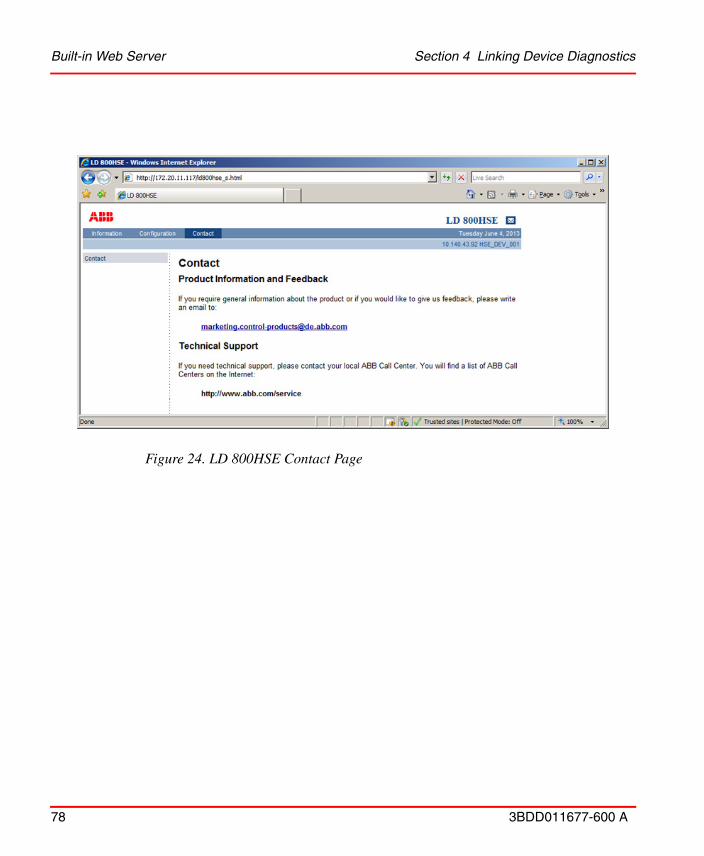
Built-in Web Server Section 4 Linking Device Diagnostics
78 3BDD011677-600 A
Figure 24. LD 800HSE Contact Page

Section 4 Linking Device Diagnostics System Status
3BDD011677-600 A 79
System Status
Figure 25 shows an example of the system status information which can be read from the linking device.
This web page indicates identification information and the effective IP configuration of the linking device as explained in Table 14
Figure 25. System Status
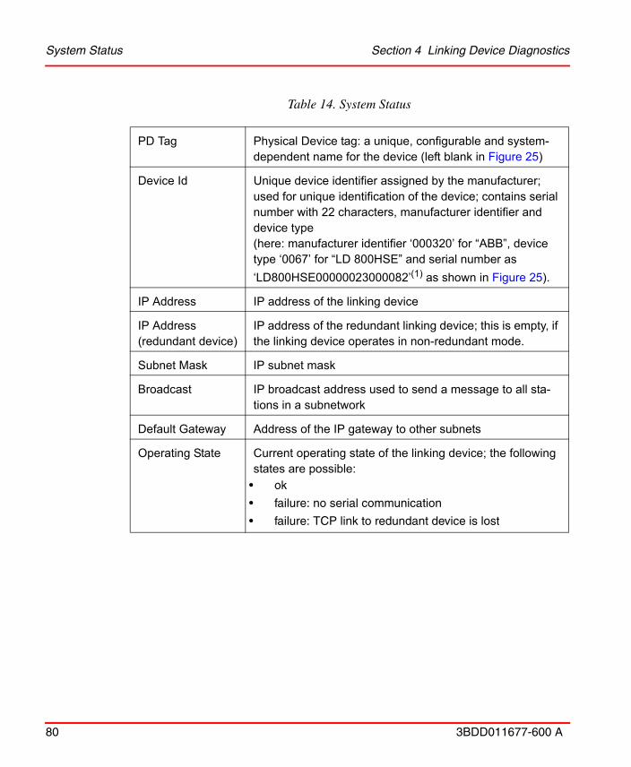
System Status Section 4 Linking Device Diagnostics
80 3BDD011677-600 A
Table 14. System Status
PD Tag Physical Device tag: a unique, configurable and system-dependent name for the device (left blank in Figure 25)
Device Id Unique device identifier assigned by the manufacturer; used for unique identification of the device; contains serial number with 22 characters, manufacturer identifier and device type (here: manufacturer identifier ‘000320’ for “ABB”, device type ‘0067’ for “LD 800HSE” and serial number as
‘LD800HSE00000023000082’(1) as shown in Figure 25).
IP Address IP address of the linking device
IP Address(redundant device)
IP address of the redundant linking device; this is empty, if the linking device operates in non-redundant mode.
Subnet Mask IP subnet mask
Broadcast IP broadcast address used to send a message to all sta-tions in a subnetwork
Default Gateway Address of the IP gateway to other subnets
Operating State Current operating state of the linking device; the following states are possible:
• ok
• failure: no serial communication
• failure: TCP link to redundant device is lost
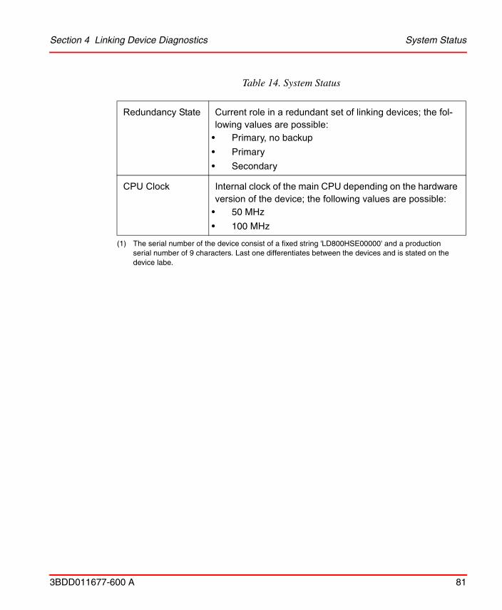
Section 4 Linking Device Diagnostics System Status
3BDD011677-600 A 81
Redundancy State Current role in a redundant set of linking devices; the fol-lowing values are possible:
• Primary, no backup
• Primary
• Secondary
CPU Clock Internal clock of the main CPU depending on the hardware version of the device; the following values are possible:
• 50 MHz
• 100 MHz
(1) The serial number of the device consist of a fixed string 'LD800HSE00000' and a production serial number of 9 characters. Last one differentiates between the devices and is stated on the device labe.
Table 14. System Status

System Diagnostics Section 4 Linking Device Diagnostics
82 3BDD011677-600 A
System Diagnostics
Figure 26 shows an example of the system diagnostics information which can be read from the linking device.
This web page indicates system diagnostics information of the linking device as explained in Table 15.
Figure 26. System Diagnostics

Section 4 Linking Device Diagnostics System Diagnostics
3BDD011677-600 A 83
Table 15. System Diagnostics
System Uptime Elapsed time since and time of last reboot.
Memory Load Usage of the system memory (RAM).
Date System time of the linking device. When the device is restarted the system time is initialized withSun Jan 1 00:00:00 UTC 2008. This time will reflect the actual time as soon as a SNTP time server is accessible.
HSE Frame Statistics Total number of HSE telegrams for various catego-ries since reboot and number of telegrams per sec-ond (moving average). The moving average values give an indication of the system load.
Ethernet Statistics Total number of received/transmitted octets and packets on the Ethernet port since reboot.
Total number of errors due to collisions or other faults since reboot.
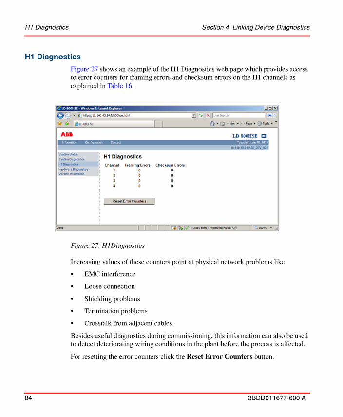
H1 Diagnostics Section 4 Linking Device Diagnostics
84 3BDD011677-600 A
H1 Diagnostics
Figure 27 shows an example of the H1 Diagnostics web page which provides access to error counters for framing errors and checksum errors on the H1 channels as explained in Table 16.
Increasing values of these counters point at physical network problems like
• EMC interference
• Loose connection
• Shielding problems
• Termination problems
• Crosstalk from adjacent cables.
Besides useful diagnostics during commissioning, this information can also be used to detect deteriorating wiring conditions in the plant before the process is affected.
For resetting the error counters click the Reset Error Counters button.
Figure 27. H1Diagnostics
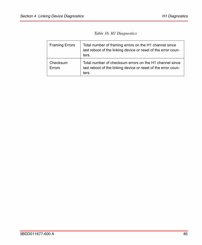
Section 4 Linking Device Diagnostics H1 Diagnostics
3BDD011677-600 A 85
Table 16. H1 Diagnostics
Framing Errors Total number of framing errors on the H1 channel since last reboot of the linking device or reset of the error coun-ters.
Checksum Errors
Total number of checksum errors on the H1 channel since last reboot of the linking device or reset of the error coun-ters.

Hardware Diagnostics Section 4 Linking Device Diagnostics
86 3BDD011677-600 A
Hardware Diagnostics
Figure 28 shows an example of the Hardware Diagnostics page. This page indicates the results of the power-on self-tests executed during start-up of the device. For details on the hardware tests see Test Cases on page 75.
possible test results are:
• failed: test failed
• ok: test passed successfully
• ne: test was not executed
Figure 28. Hardware Diagnostics
Supplementary RAM tests can be performed by clicking the button Enable Extended RAM Test and Reboot on the web page RAM Test Configuration in the Configuration menu (see RAM Test Configuration on page 71). The extended RAM tests will be performed once during the next system restart.
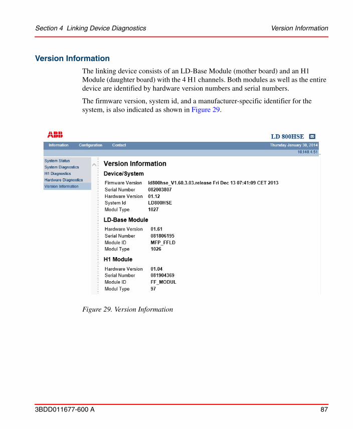
Section 4 Linking Device Diagnostics Version Information
3BDD011677-600 A 87
Version Information
The linking device consists of an LD-Base Module (mother board) and an H1 Module (daughter board) with the 4 H1 channels. Both modules as well as the entire device are identified by hardware version numbers and serial numbers.
The firmware version, system id, and a manufacturer-specific identifier for the system, is also indicated as shown in Figure 29.
Figure 29. Version Information
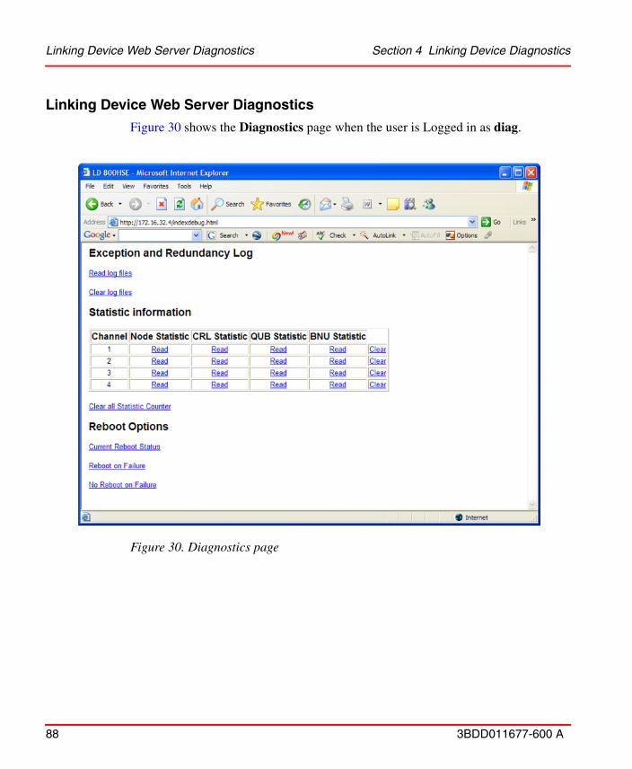
Linking Device Web Server Diagnostics Section 4 Linking Device Diagnostics
88 3BDD011677-600 A
Linking Device Web Server Diagnostics
Figure 30 shows the Diagnostics page when the user is Logged in as diag.
Figure 30. Diagnostics page
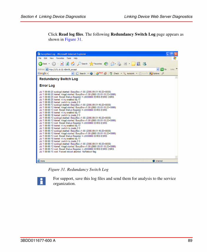
Section 4 Linking Device Diagnostics Linking Device Web Server Diagnostics
3BDD011677-600 A 89
Click Read log files. The following Redundancy Switch Log page appears as shown in Figure 31.
Figure 31. Redundancy Switch Log
For support, save this log files and send them for analysis to the service organization.
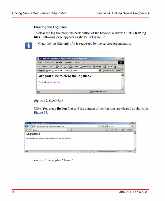
Linking Device Web Server Diagnostics Section 4 Linking Device Diagnostics
90 3BDD011677-600 A
Clearing the Log Files
To clear the log file press the back button of the browser window. Click Clear log files. Following page appears as shown in Figure 32.
Click Yes, clear the log files and the content of the log files are cleared as shown in Figure 33.
Clear the log files only if it is requested by the service organization.
Figure 32. Clear Log
Figure 33. Log files Cleared

Section 4 Linking Device Diagnostics Linking Device Web Server Diagnostics
3BDD011677-600 A 91
Clearing the Error Buffer
Click Clear error buffer in the indexdebug.html page. Following page appears shown in Figure 34.
Click Yes, clear the error buffer and the content of the buffer is deleted. Following page appears shown in Figure 35.
Clear the error buffer only if it is requested by the service organization.
Figure 34. Clear Buffer
Figure 35. Clear Error Buffer
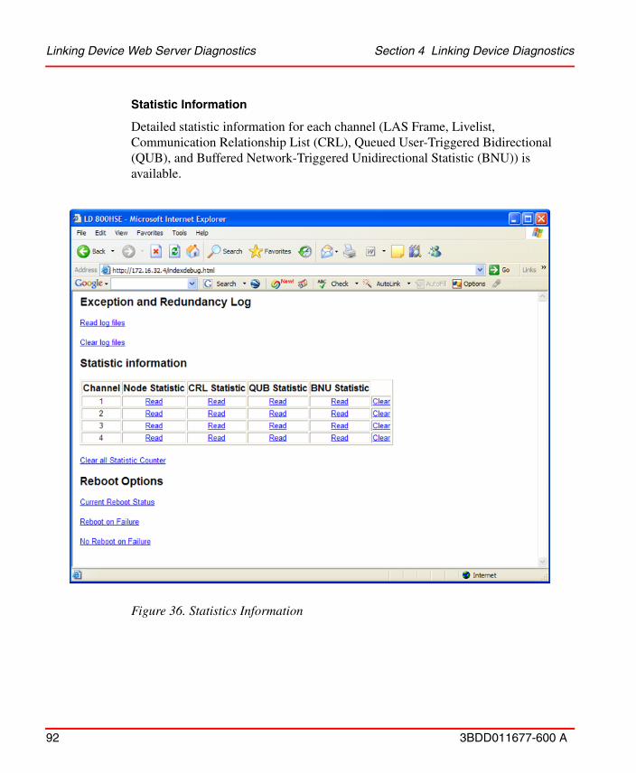
Linking Device Web Server Diagnostics Section 4 Linking Device Diagnostics
92 3BDD011677-600 A
Statistic Information
Detailed statistic information for each channel (LAS Frame, Livelist, Communication Relationship List (CRL), Queued User-Triggered Bidirectional (QUB), and Buffered Network-Triggered Unidirectional Statistic (BNU)) is available.
Figure 36. Statistics Information

Section 4 Linking Device Diagnostics Linking Device Web Server Diagnostics
3BDD011677-600 A 93
Click Read to see the detailed statistic for each channel. By pressing the Clear of the corresponding channels the statistic of each channel is deleted.
To clear all statistics at one time press the Clear all Statistic Counter.
Internal Device Information
These options are for service personal only.
Clear the statistics counter only if it is requested by the service organization.

Linking Device Web Server Diagnostics Section 4 Linking Device Diagnostics
94 3BDD011677-600 A

Appendix A Technical Data
3BDD011677-600 A 95
Appendix A Technical Data
The following table details the technical data of LD 800HSE device:
Power Supply Supply voltage 24 V DC (+- 20%)
Power consumption typ. 200 mA
Mechanical Properties
Dimensions (length x height x width)47 x 131 x 111 mm,mounted on DIN rail 35 mm (DIN EN 50 022)
Weight approx. 0.4 kg
Degree of protection IP 20
Environmental Conditions
Operating temperature 0° C .. +55° C,non-vertical mounting and hampered air convection may reduce upper temperature limit
Storage temperature -20° C ... +70° C
Relative humidity 0%...95%, non-condensing
Ethernet Interface
Number of channels 1
Port Ethernet 10BASE-T/100BASE-TX, RJ45
Transfer rates 10 Mbit/s or 100 Mbit/s (autosensing)

Appendix A Technical Data
96 3BDD011677-600 A
H1 Fieldbus Interface
Number of channels 4
Port FF H1 3-pole screw terminals (pluggable), transformer coupling,galvanically isolated
Physical layer profile type 114, standard power signalling, separately powered, not intrinsically safe
Transfer rate 31.25 kbit/s
Serial Interface Port 9-pole SubD male RS-232, 115.2 kbit/s
Certifications CE Compliance according to EMC Directive 89/336/EECEN 61000-6-2, EN 61000-6-4FCC Part 15 Subpart B Class AVCCI Class A Information Technology Equipment (ITE)UL 508, CSA C22.2 No. 14-M95ABB Industrial IT enabled
Accessories Redundancy Link Cable 0,5 m (to be ordered separately)
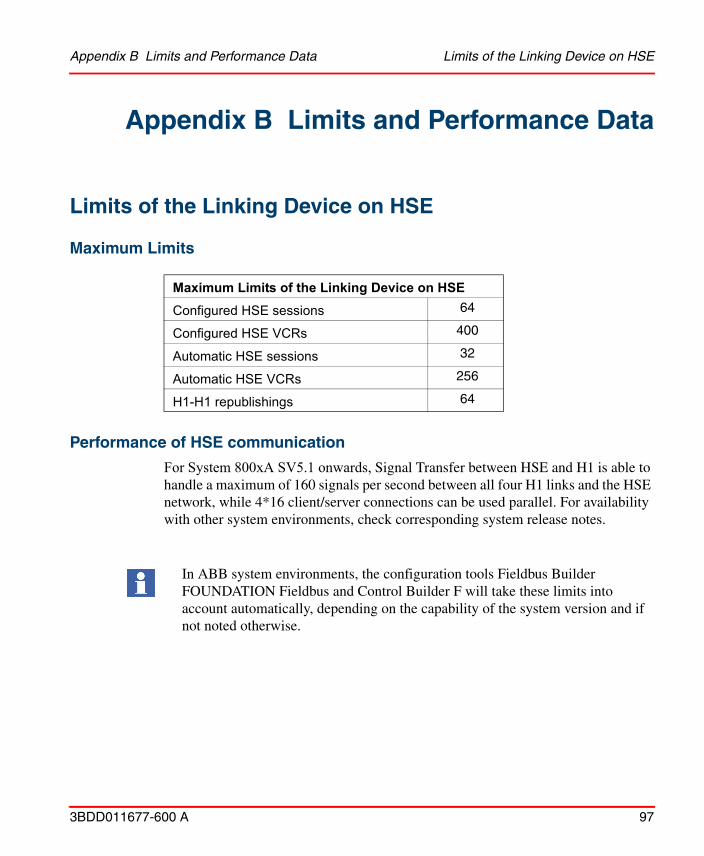
Appendix B Limits and Performance Data Limits of the Linking Device on HSE
3BDD011677-600 A 97
Appendix B Limits and Performance Data
Limits of the Linking Device on HSE
Maximum Limits
Performance of HSE communication
For System 800xA SV5.1 onwards, Signal Transfer between HSE and H1 is able to handle a maximum of 160 signals per second between all four H1 links and the HSE network, while 4*16 client/server connections can be used parallel. For availability with other system environments, check corresponding system release notes.
Maximum Limits of the Linking Device on HSE
Configured HSE sessions 64
Configured HSE VCRs 400
Automatic HSE sessions 32
Automatic HSE VCRs 256
H1-H1 republishings 64
In ABB system environments, the configuration tools Fieldbus Builder FOUNDATION Fieldbus and Control Builder F will take these limits into account automatically, depending on the capability of the system version and if not noted otherwise.
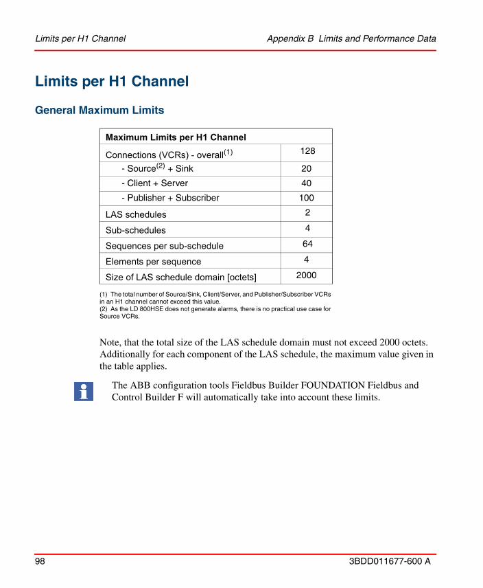
Limits per H1 Channel Appendix B Limits and Performance Data
98 3BDD011677-600 A
Limits per H1 Channel
General Maximum Limits
Note, that the total size of the LAS schedule domain must not exceed 2000 octets. Additionally for each component of the LAS schedule, the maximum value given in the table applies.
Maximum Limits per H1 Channel
Connections (VCRs) - overall(1)
(1) The total number of Source/Sink, Client/Server, and Publisher/Subscriber VCRs in an H1 channel cannot exceed this value.
128
- Source(2) + Sink
(2) As the LD 800HSE does not generate alarms, there is no practical use case for Source VCRs.
20
- Client + Server 40
- Publisher + Subscriber 100
LAS schedules 2
Sub-schedules 4
Sequences per sub-schedule 64
Elements per sequence 4
Size of LAS schedule domain [octets] 2000
The ABB configuration tools Fieldbus Builder FOUNDATION Fieldbus and Control Builder F will automatically take into account these limits.
Appendix B Limits and Performance Data Performance
3BDD011677-600 A 99
Performance
H1 Slot Time
Duration of Redundancy Switch-overDuring redundancy switch-over, the activity on H1 links is interrupted. From the perspective of a single H1 device, publishing or subscribing a process value is interrupted for a period of time that is composed of the following times:
• fault detection time tfd
• redundancy switching time trs
• macro cycle duration tmc
The time of inactivity due to redundancy switch-over for a single process value is therefore:
• time of inactivity ≤ tfd + trs + tmccompared to tmc during regular operation.
The fault detection time is:
• tfd ≤ 800 ms if the Primary Device fails.
• tfd ≤ 500 ms if the Ethernet connection on the Primary Device is removed.1
Make sure that in your configuration the maximum number of 40 republished signals per second per H1 link is not exceeded.
Please Note: Signals exchanged between H1 devices are not affected. This limit only affects signals, which have a connection to LD 800HSE.
The H1 bus parameter “SlotTime” has to be less than 50. Otherwise, the maximum time of inactivity on an H1 link would exceed 200 ms, which in turn would have an impact on the fault detection time (i.e. a failure in an H1 channel could not be detected within the currently used fault detection time).
Please note: Certain configurations of bus parameters (SlotTime, MaxResponseDelay, MinInterPDUDelay) can reduce the possible maximum numbers of republished signals per second and H1 link.
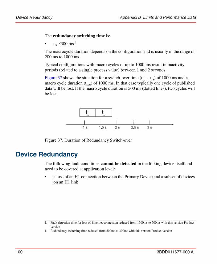
Device Redundancy Appendix B Limits and Performance Data
100 3BDD011677-600 A
The redundancy switching time is:
• trs ≤ 300 ms.1
The macrocycle duration depends on the configuration and is usually in the range of 200 ms to 1000 ms.
Typical configurations with macro cycles of up to 1000 ms result in inactivity periods (related to a single process value) between 1 and 2 seconds.
Figure 37 shows the situation for a switch-over time (tfd + trs) of 1000 ms and a macro cycle duration (tmc) of 1000 ms. In that case typically one cycle of published data will be lost. If the macro cycle duration is 500 ms (dotted lines), two cycles will be lost.
Device RedundancyThe following fault conditions cannot be detected in the linking device itself and need to be covered at application level:
• a loss of an H1 connection between the Primary Device and a subset of devices on an H1 link
1. Fault detection time for loss of Ethernet connection reduced from 1500ms to 500ms with this version Product version
1. Redundancy switching time reduced from 500ms to 300ms with this version Product version
Figure 37. Duration of Redundancy Switch-over

Appendix B Limits and Performance Data Device Redundancy
3BDD011677-600 A 101
• a loss of an H1 connection between the Secondary Device and the entire H1 link or a subset of devices on an H1 link.
Make sure not to permute the H1 terminal blocks, An accidental permutation of the H1 link connections at the secondary linking device will not be detected right away. On application level, detection will not be possible before a redundancy switch-over takes place or the live lists of primary and secondary linking device are being compared manually.

Device Redundancy Appendix B Limits and Performance Data
102 3BDD011677-600 A
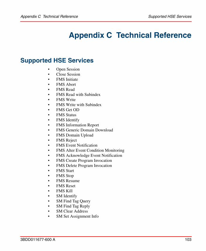
Appendix C Technical Reference Supported HSE Services
3BDD011677-600 A 103
Appendix C Technical Reference
Supported HSE Services• Open Session• Close Session• FMS Initiate• FMS Abort• FMS Read• FMS Read with Subindex• FMS Write• FMS Write with Subindex• FMS Get OD• FMS Status• FMS Identify• FMS Information Report• FMS Generic Domain Download• FMS Domain Upload• FMS Reject• FMS Event Notification• FMS Alter Event Condition Monitoring• FMS Acknowledge Event Notification• FMS Create Program Invocation• FMS Delete Program Invocation• FMS Start• FMS Stop• FMS Resume• FMS Reset• FMS Kill• SM Identify• SM Find Tag Query• SM Find Tag Reply• SM Clear Address• SM Set Assignment Info
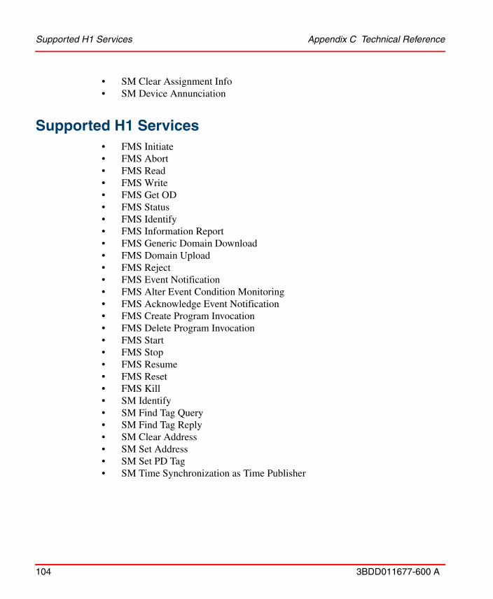
Supported H1 Services Appendix C Technical Reference
104 3BDD011677-600 A
• SM Clear Assignment Info• SM Device Annunciation
Supported H1 Services• FMS Initiate• FMS Abort• FMS Read• FMS Write• FMS Get OD• FMS Status• FMS Identify• FMS Information Report• FMS Generic Domain Download• FMS Domain Upload• FMS Reject• FMS Event Notification• FMS Alter Event Condition Monitoring• FMS Acknowledge Event Notification• FMS Create Program Invocation• FMS Delete Program Invocation• FMS Start• FMS Stop• FMS Resume• FMS Reset• FMS Kill• SM Identify• SM Find Tag Query• SM Find Tag Reply• SM Clear Address• SM Set Address• SM Set PD Tag• SM Time Synchronization as Time Publisher
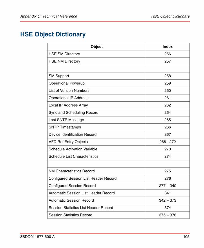
Appendix C Technical Reference HSE Object Dictionary
3BDD011677-600 A 105
HSE Object Dictionary
Object Index
HSE SM Directory 256
HSE NM Directory 257
SM Support 258
Operational Powerup 259
List of Version Numbers 260
Operational IP Address 261
Local IP Address Array 262
Sync and Scheduling Record 264
Last SNTP Message 265
SNTP Timestamps 266
Device Identification Record 267
VFD Ref Entry Objects 268 - 272
Schedule Activation Variable 273
Schedule List Characteristics 274
NM Characteristics Record 275
Configured Session List Header Record 276
Configured Session Record 277 – 340
Automatic Session List Header Record 341
Automatic Session Record 342 – 373
Session Statistics List Header Record 374
Session Statistics Record 375 – 378
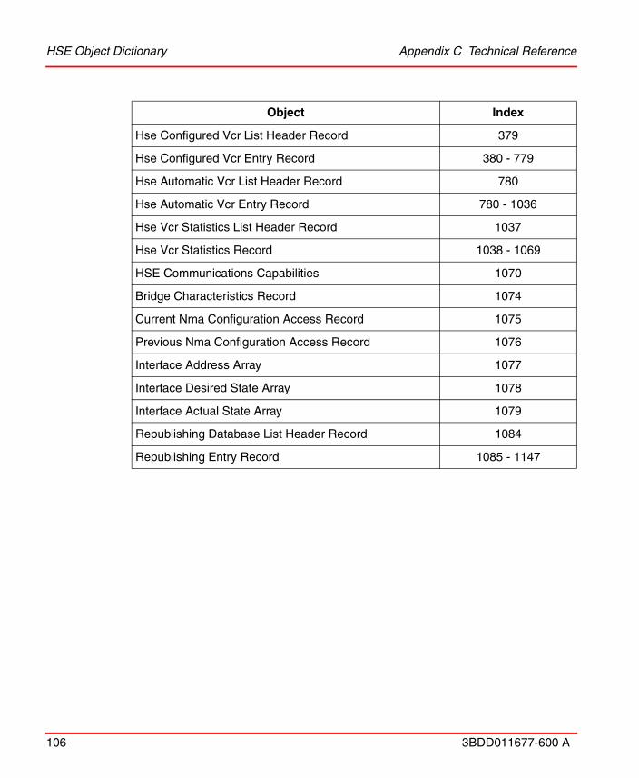
HSE Object Dictionary Appendix C Technical Reference
106 3BDD011677-600 A
Hse Configured Vcr List Header Record 379
Hse Configured Vcr Entry Record 380 - 779
Hse Automatic Vcr List Header Record 780
Hse Automatic Vcr Entry Record 780 - 1036
Hse Vcr Statistics List Header Record 1037
Hse Vcr Statistics Record 1038 - 1069
HSE Communications Capabilities 1070
Bridge Characteristics Record 1074
Current Nma Configuration Access Record 1075
Previous Nma Configuration Access Record 1076
Interface Address Array 1077
Interface Desired State Array 1078
Interface Actual State Array 1079
Republishing Database List Header Record 1084
Republishing Entry Record 1085 - 1147
Object Index
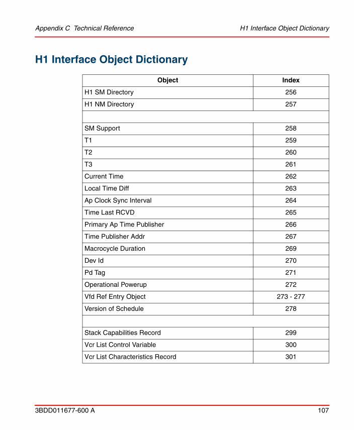
Appendix C Technical Reference H1 Interface Object Dictionary
3BDD011677-600 A 107
H1 Interface Object Dictionary
Object Index
H1 SM Directory 256
H1 NM Directory 257
SM Support 258
T1 259
T2 260
T3 261
Current Time 262
Local Time Diff 263
Ap Clock Sync Interval 264
Time Last RCVD 265
Primary Ap Time Publisher 266
Time Publisher Addr 267
Macrocycle Duration 269
Dev Id 270
Pd Tag 271
Operational Powerup 272
Vfd Ref Entry Object 273 - 277
Version of Schedule 278
Stack Capabilities Record 299
Vcr List Control Variable 300
Vcr List Characteristics Record 301

H1 Interface Object Dictionary Appendix C Technical Reference
108 3BDD011677-600 A
Vcr Static Entry Record 302 – 429(302 cannot be written)
Vcr Dynamic Entry Record 430 – 557
Vcr Statistics Entry Record not supported
Dlme Basic Characteristics Record 686
Dlme Basic Info Record 687
Dlme Basic Statistics Record not supported
Dlme Link Master Capabilities Variable 689
Dlme Link Master Info Record 690
Primary Link Master Flag Variable 691
Live List Status Array Variable 692
Max Token Hold Time Array 693(access via
ReadWithSubindex or WriteWithSubindex)
Boot Operate Functional Class 694
Current Link Settings Record 695
Configured Link Settings Record 696
Dlme Link Master Statistics Record not supported
Last Values Record not supported
Link Schedule Activation Variable 699
Link Schedule List Characteristics Record 700(object cannot be
written)
Schedule Descriptor Record 701 – 702(object cannot be
written)
Object Index
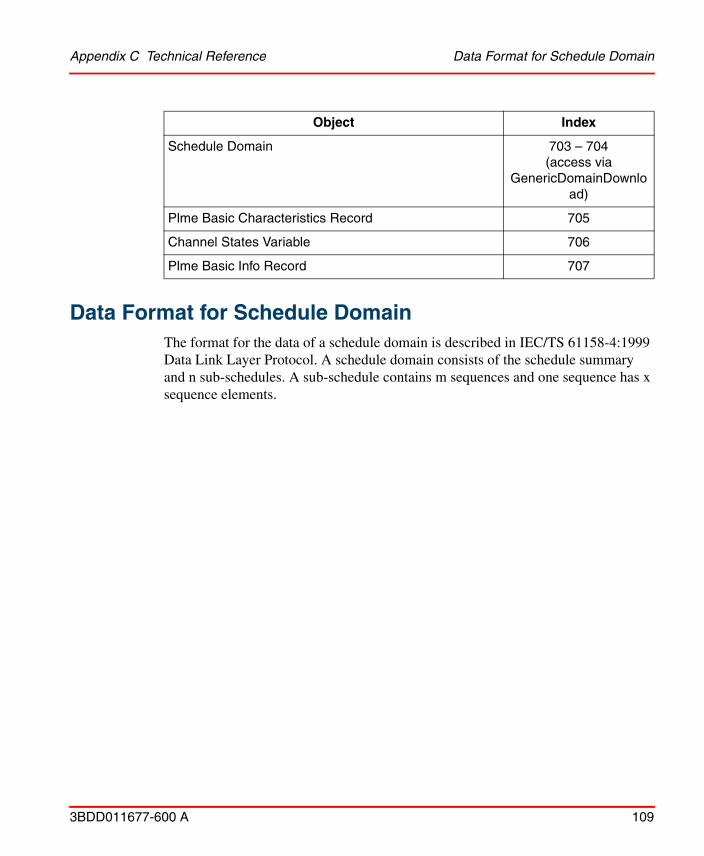
Appendix C Technical Reference Data Format for Schedule Domain
3BDD011677-600 A 109
Data Format for Schedule Domain
The format for the data of a schedule domain is described in IEC/TS 61158-4:1999 Data Link Layer Protocol. A schedule domain consists of the schedule summary and n sub-schedules. A sub-schedule contains m sequences and one sequence has x sequence elements.
Schedule Domain 703 – 704(access via
GenericDomainDownload)
Plme Basic Characteristics Record 705
Channel States Variable 706
Plme Basic Info Record 707
Object Index

Schedule Summary Appendix C Technical Reference
110 3BDD011677-600 A
Schedule Summary
Meaning Range of values Octets
schedule identifier 0xff 1
transfer version number 0 - 7 1
schedule version 1 - 0xffff 2
builder identifier 0x100 - 0xfff 2
number sub-schedules 1 - 4 1
V(MSO) unused 1
storage for schedule 2
resolution unused 2
V(MRD)*V(ST) unused 2
ThisLink of Originator unused 2
periodic time base unused 6
macrocycle duration 1 - 0xffffffff 4
sub-schedule reference 1 1 - 0xffff 2
sub-schedule reference i 1 - 0xffff 2
sub-schedule reference n 1 - 0xffff 2
end of summary 0 2 * l, I = 1, 2, 3, ...
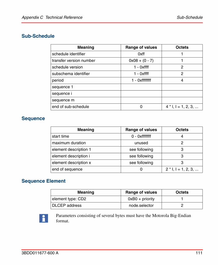
Appendix C Technical Reference Sub-Schedule
3BDD011677-600 A 111
Sub-Schedule
Sequence
Sequence Element
Meaning Range of values Octets
schedule identifier 0xff 1
transfer version number 0x08 + (0 - 7) 1
schedule version 1 - 0xffff 2
subschema identifier 1 - 0xffff 2
period 1 - 0xffffffff 4
sequence 1
sequence i
sequence m
end of sub-schedule 0 4 * l, I = 1, 2, 3, ...
Meaning Range of values Octets
start time 0 - 0xffffffff 4
maximum duration unused 2
element description 1 see following 3
element description i see following 3
element description x see following 3
end of sequence 0 2 * I, I = 1, 2, 3, ...
Meaning Range of values Octets
element type: CD2 0xB0 + priority 1
DLCEP address node.selector 2
Parameters consisting of several bytes must have the Motorola Big-Endian format.

Redundancy Appendix C Technical Reference
112 3BDD011677-600 A
RedundancyFOUNDATION fieldbus is also a distributed control architecture that provides increased availability compared to centralized control architectures. But as a linking device acts as gateway between H1 links and the HSE subnet it represents a bottleneck concerning the availability of communication paths leading from HSE to H1 and vice versa.
To improve the availability of the LD 800HSE, it is possible to combine two linking devices which then form a redundant linking device, that behaves logically like one device.
Redundancy Concept
A redundant linking device (also called “a redundant set of devices”) consists of two physical linking devices that are connected to the same HSE subnet and to the
Figure 38. System Topology
Appendix C Technical Reference Redundancy Concept
3BDD011677-600 A 113
same H1 links. The redundant set of devices behaves like one logical linking device. By duplicating the physical linking device, it is possible to tolerate one fault in one of the two devices.
In a redundant set of devices one linking device acts as Primary Device and performs actively all communication functions, including the Link Active Scheduler (LAS) function on the H1 links. In a redundant set it is the Primary Device that has to be addressed by hosts and configuration tools.
The second linking device, named Secondary Device, acts as backup device. It receives automatically the same configuration as the Primary Device, but uses different node addresses on the H1 links and a different IP address on HSE.
The Secondary Device is able to take over the function of the Primary Device if the Primary Device fails. In that case the linking device is reduced to a non-redundant system that is not able to tolerate any further failure. Therefore it is necessary to replace the defective device as soon as possible to recover redundancy.
The Secondary Device acts as Backup Link Master on each H1 link attempting to take over the LAS role if required. Additional Link Master devices may be configured to act as Backup Link Master on the H1 links.
The two devices forming a redundant set communicate via a serial communication line (RS-232) and via Ethernet. The serial line is used to establish a redundant set of devices, to exchange signs of life, and to control redundancy switch-over, while the Ethernet is used to transfer configuration information from the Primary Device to the Secondary Device. Therefore an operational serial communication path and an operational Ethernet path between both devices are required for proper operation.
The two physical linking devices forming a redundant set of devices are determined by the serial link between them. Without that serial link, both devices operate like independent, non-redundant Primary Devices.

Fault Domain Appendix C Technical Reference
114 3BDD011677-600 A
Fault Domain
The shaded area in Figure 39 shows the fault domain. Faults within the fault domain can be detected and covered by the redundancy features. Those are:
• permanent faults within the linking device - (1)
• transient faults within a linking device that lead to loss of functions - (1)
• a loss of the serial connection between the two linking devices - (2)
• a failure in the Ethernet communication between the two linking devices - (3)
• a loss of an H1 connection between the Primary Device and the entire H1 link; this may be caused by disconnecting an H1 cable from the Primary Device - (4a) if LD1 acts as Primary Device; (4b) if LD2 acts as Primary Device).
Figure 39. Fault Domain
Detecting a loss of an H1 connection between the Primary Device and the entire H1 link requires that at least two H1 devices have been connected to that H1 channel of the linking device and have appeared in the H1 Live List before the loss of the connection occurs.

Appendix C Technical Reference Fault Domain
3BDD011677-600 A 115
The following fault conditions cannot be detected and covered:
• a loss of an H1 connection between the Primary Device and a subset of devices on an H1 link
• a loss of an H1 connection between the Secondary Device and the entire H1 link or a subset of devices on an H1 link.
The conditions for a switch-over from the Primary Device to the Secondary Device are listed below.
Transfer from Primary Device to Secondary Device
The Primary Device transfers its role to the Secondary Device
The Secondary Device accepts the transfer
Only one of the listed faults may be present at a time. Another fault cannot be tolerated until the redundant set has been repaired and a fully operational Secondary Device is available.
if host system or configuration tool request to transfer the role
or the Primary Device detects a failure of its own Ethernet port
or the Primary Device detects a failure on at least one H1 interface
or the Primary Device detects a loss of the connection to all devices on an H1 link.(1)
(1) This requires that at least two devices have been connected to that H1 channel of the linking device and have appeared in the H1 Live List before the loss of the connection occurs.
if its H1 interfaces are operational and faultless
and its Ethernet port is operational
and it has a valid configuration.

Fault Domain Appendix C Technical Reference
116 3BDD011677-600 A
Take Over of Primary Role
The Secondary Device takes over the primary role
Restoring Redundancy
Only one of the listed faults may be present at a time. Another fault cannot be tolerated until the redundant set has been repaired and a fully operational Secondary Device is available.
The required measures for repairing the redundant set of devices depend on the present fault. For an overview refer to Table 17.
if the serial connection to the Primary Device is lost
and it acts as Link Active Scheduler on all configured H1 links
and its Ethernet port is operational.
Table 17. Measures for Repairing a Redundant Set of Devices
Fault Measure of Repair
Permanent fault within the linking device
Replacement of the defective linking device.
Transient fault within the linking device
Restart of the linking device (performed automatically).
Loss of the serial connection between the two linking devices
Re-establishment of the serial connection.
Loss of the Ethernet connection between the two linking devices
Re-establishment of the Ethernet connection.
Loss of an H1 connection between the Primary Device and the entire H1 link
Re-establishment of the H1 connection.
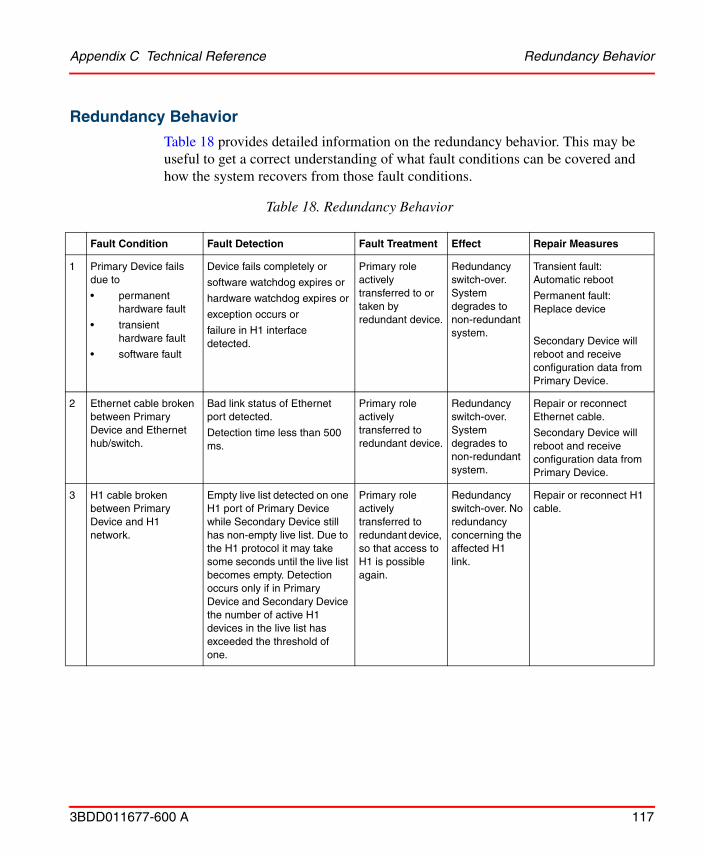
Appendix C Technical Reference Redundancy Behavior
3BDD011677-600 A 117
Redundancy Behavior
Table 18 provides detailed information on the redundancy behavior. This may be useful to get a correct understanding of what fault conditions can be covered and how the system recovers from those fault conditions.
Table 18. Redundancy Behavior
Fault Condition Fault Detection Fault Treatment Effect Repair Measures
1 Primary Device fails due to
• permanent hardware fault
• transient hardware fault
• software fault
Device fails completely or
software watchdog expires or
hardware watchdog expires or
exception occurs or
failure in H1 interface detected.
Primary role actively transferred to or taken by redundant device.
Redundancy switch-over. System degrades to non-redundant system.
Transient fault: Automatic reboot
Permanent fault: Replace device
Secondary Device will reboot and receive configuration data from Primary Device.
2 Ethernet cable broken between Primary Device and Ethernet hub/switch.
Bad link status of Ethernet port detected.
Detection time less than 500 ms.
Primary role actively transferred to redundant device.
Redundancy switch-over. System degrades to non-redundant system.
Repair or reconnect Ethernet cable.
Secondary Device will reboot and receive configuration data from Primary Device.
3 H1 cable broken between Primary Device and H1 network.
Empty live list detected on one H1 port of Primary Device while Secondary Device still has non-empty live list. Due to the H1 protocol it may take some seconds until the live list becomes empty. Detection occurs only if in Primary Device and Secondary Device the number of active H1 devices in the live list has exceeded the threshold of one.
Primary role actively transferred to redundant device, so that access to H1 is possible again.
Redundancy switch-over. No redundancy concerning the affected H1 link.
Repair or reconnect H1 cable.

Redundancy Behavior Appendix C Technical Reference
118 3BDD011677-600 A
4 Secondary Device fails due to
• permanent hardware fault
• transient hardware fault
• software fault
Device fails completely or
software watchdog expires or
hardware watchdog expires or
exception occurs or
failure in H1 interface detected.
Secondary Device assumes and indicates non-operational state.
System degrades to non-redundant system.
Transient fault: Automatic reboot
Permanent fault: Replace device
Secondary Device will reboot and receive configuration data from Primary Device.
5 Ethernet cable broken between Secondary Device and Ethernet hub/switch.
Bad link status of Ethernet port detected.
Detection time less than 500 ms.
Secondary Device assumes and indicates non-operational state.
System degrades to non-redundant system.
Repair or reconnect Ethernet cable.
Secondary Device will reboot and receive configuration data from Primary Device.
6 H1 cable broken between Secondary Device and H1 network.(1)
No fault detection in Secondary Device.
Empty live list has to be detected by any HSE client (e. g. asset monitor).
None. No redundancy concerning the affected H1 link.
Repair or reconnect H1 cable.
7 TCP connection lost between Primary Device and Secondary Device.
Time-out on TCP connection.
Detection time less than 2 sec during activity and less than 7 sec during idle times.
Secondary Device assumes and indicates non-operational state(2)
System degrades to non-redundant system. Secondary Device clears configuration.
Repair Ethernet connection.
Secondary Device may reboot in some cases depending on prior state and will receive configuration data from Primary Device.
8 Redundancy link broken or removed between Primary Device and Secondary Device for more than 11 sec.
Loss of serial communication.
Detection time less than 800 ms.
Secondary Device assumes and indicates non-operational state after 11 sec.
System degrades to non-redundant system after 11 sec.
Repair or reconnect redundancy link.
Secondary Device will reboot and receive configuration data from Primary Device.
Table 18. Redundancy Behavior
Fault Condition Fault Detection Fault Treatment Effect Repair Measures
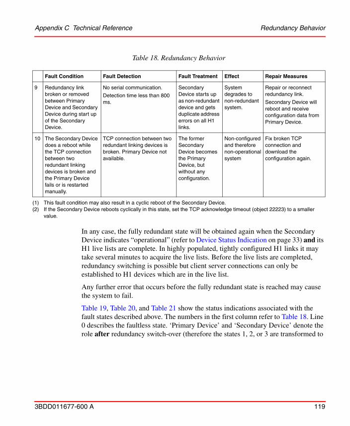
Appendix C Technical Reference Redundancy Behavior
3BDD011677-600 A 119
In any case, the fully redundant state will be obtained again when the Secondary Device indicates “operational” (refer to Device Status Indication on page 33) and its H1 live lists are complete. In highly populated, tightly configured H1 links it may take several minutes to acquire the live lists. Before the live lists are completed, redundancy switching is possible but client server connections can only be established to H1 devices which are in the live list.
Any further error that occurs before the fully redundant state is reached may cause the system to fail.
Table 19, Table 20, and Table 21 show the status indications associated with the fault states described above. The numbers in the first column refer to Table 18. Line 0 describes the faultless state. ‘Primary Device’ and ‘Secondary Device’ denote the role after redundancy switch-over (therefore the states 1, 2, or 3 are transformed to
9 Redundancy link broken or removed between Primary Device and Secondary Device during start up of the Secondary Device.
No serial communication.
Detection time less than 800 ms.
Secondary Device starts up as non-redundant device and gets duplicate address errors on all H1 links.
System degrades to non-redundant system.
Repair or reconnect redundancy link.
Secondary Device will reboot and receive configuration data from Primary Device.
10 The Secondary Device does a reboot while the TCP connection between two redundant linking devices is broken and the Primary Device fails or is restarted manually.
TCP connection between two redundant linking devices is broken. Primary Device not available.
The former Secondary Device becomes the Primary Device, but without any configuration.
Non-configured and therefore non-operational system
Fix broken TCP connection and download the configuration again.
(1) This fault condition may also result in a cyclic reboot of the Secondary Device.(2) If the Secondary Device reboots cyclically in this state, set the TCP acknowledge timeout (object 22223) to a smaller
value.
Table 18. Redundancy Behavior
Fault Condition Fault Detection Fault Treatment Effect Repair Measures
Redundancy Behavior Appendix C Technical Reference
120 3BDD011677-600 A
the states 4, 5, or 6, because the faulty Primary Device turns into a faulty Secondary Device after redundancy switch-over).
The device status indication depends on the hardware version of the LD Base Module. To allow enhanced device status indication newer hardware is equipped with two-colored F- and R-LEDs, refer to Device Status Indication on page 33 to find out, which device status indication applies to your hardware.

Appendix C Technical Reference Redundancy Behavior
3BDD011677-600 A 121
Table 19. Indication of Fault States with Single-colored LEDs
Primary Device Secondary Device
F / R H1-LEDs Web-Info F / R H1-LEDs Web-Info
conf. link
unconf. link
conf. link
unconf. link
missing link
0 F okPrimary
F n. a. okSecondary
R R
1, 4
F failure no serial communicationPrimary, no backup
F n. a. (no connection to web server)
R R
2, 5
F failure TCP link to redundant device is lostPrimary, no backup
F n. a. (no connection to web server)
R R
3, 6
F okPrimary
F okSecondary
R R
7 F failure TCP link to redundant device is lostPrimary, no backup(if connection to web server possible)
F n. a. failure TCP link to redundant device is lostSecondary(if connection to web server possible)
R R
8 F failure no serial communicationPrimary, no backup
F n. a. failure no serial communicationSecondaryR R
9 F okPrimary
F n. a. configuration errorPrimary
R R

Redundancy Behavior Appendix C Technical Reference
122 3BDD011677-600 A
Table 20. Indication of Fault States with Two-colored F-LEDs
Primary Device Secondary Device
F / R H1-LEDs Web-Info F / R H1-LEDs Web-Info
conf. link
unconf. link
conf. link
unconf. link
missing link
0 F okPrimary
F n. a. okSecondary
R R
1, 4
F failure no serial communicationPrimary, no backup
F n. a. (no connection to web server)
R R
2, 5
F failure TCP link to redundant device is lostPrimary, no backup
F n. a. (no connection to web server)
R R
3, 6
F okPrimary
F okSecondary
R R
7 F failure TCP link to redundant device is lostPrimary, no backup(if connection to web server possible)
F n. a. failure TCP link to redundant device is lostSecondary(if connection to web server possible)
R R
8 F failure no serial communicationPrimary, no backup
F n. a. failure no serial communicationSecondaryR R
9 F okPrimary
F n. a. configuration errorPrimary
R R

Appendix C Technical Reference Redundancy Behavior
3BDD011677-600 A 123
Table 21. Indication of Fault States with Two-colored F- and R-LEDs
Primary Device Secondary Device
F / R H1-LEDs Web-Info F / R H1-LEDs Web-Info
conf. link
unconf. link
conf. link
unconf. link
missing link
0 F okPrimary
F n. a. okSecondary
R R
1, 4
F failure no serial communicationPrimary, no backup
F n. a. (no connection to web server)
R R
2, 5
F failure TCP link to redundant device is lostPrimary, no backup
F n. a. (no connection to web server)
R R
3, 6
F okPrimary
F okSecondary
R R
7 F failure TCP link to redundant device is lostPrimary, no backup(if connection to web server possible)
F n. a. failure TCP link to redundant device is lostSecondary(if connection to web server possible)
R R
8 F failure no serial communicationPrimary, no backup
F n. a. failure no serial communicationSecondaryR R
9 F okPrimary
F n. a. configuration errorPrimary
R R

Redundancy Behavior Appendix C Technical Reference
124 3BDD011677-600 A

Appendix D Linking Device for Zone 2 Explosion and Protection Environment General
3BDD011677-600 A 125
Appendix D Linking Device for Zone 2Explosion and Protection Environment
This section is an extension for Linking Device LD 800HSE EX hardware installation and only refers to aspects that are relevant for explosion protection on Zone 2 environment.
To ensure personal safety and implementation of both the functionality of the devices, Instruction manual must be read thoroughly before installing the linking device.
General RequirementsFollowing general requirements must be observed while installing linking device LD 800HSE EX on Zone 2:
• If the information stated in this section are not observed or in case of inappropriate handling of the linking device, our liability is waived. In addition, the warranty on devices and spare parts does not apply.
• The details of this instruction manual must be observed along with the conditions for use and the applicable details stated on the marking and type labels of each linking device.
• Any selection and operation of the device must be done as per the technical rules.
• Adequate precautions must be taken to prevent unintended actuation or impairment of the device.
• Ensure that energized conductors are not disconnected. This can be life threatening in a potentially explosive atmosphere.
• The linking device is only approved for intended use. In case of non-compliance, the warranty and manufacturer's liability does not apply.

Commissioning and Installation Appendix D Linking Device for Zone 2 Explosion and Protection
126 3BDD011677-600 A
• Ensure the installed equipment comply with the types of protection applicable to the corresponding zones.
• All connected electrical equipment must be suitable for the respective intended use.
• The operator must ensure protection against lightning in compliance with the locally applicable regulations.
• Electrostatic aspects must be considered when mounting the bus-modules.
• The hazard of any objects falling onto the bus-module must be prevented.
• If the linking device does not meet the requirements of impact protection, protection against impact energy and IP protection must be provided at the place of use as per the requirements stated in section 26.4 of IEC/EN 60079-0.
• The linking device is defined as Instruments and apparatus of low energy according to clause 23 of IEC/EN 60079-15; thus the requirement stated in sub-clause C, limiting the transient characteristic to 40% above the rated voltage, has to be adhered to when erecting the equipment.
Commissioning and InstallationThe linking device is mounted in a major system. Depending on the level of IP-protection, an interval for cleaning the apparatus (dust settlement) must be defined. Care must be taken that only equipment is installed that complies with the types of protection relevant to the applicable zones and categories.
The following important facts must be observed:
• The equipment must be installed in a protective enclosure that meets the requirements for resistance to impact as defined in the IEC/EN 60079-0, cl. 26.4.2. This enclosure must pass the environmental tests according to IEC/EN 60079-0 standards for the preferred ambient range, that is, it must be submitted to these tests (thermal endurance, impact and IP, this test sequence must be observed).
• The equipment must be used only as intended.
• The Functional Earth connection of the apparatus must be connected with the Protective Earth of the system.
Appendix D Linking Device for Zone 2 Explosion and Protection Environment Commissioning and
3BDD011677-600 A 127
• The linking device is only operated in a fully mounted and intact enclosure, if the enclosure is damaged, the operation is not permitted.
• If ambient temperature exceeds 58°C at the place of installation, the temperature of the connecting cables increases. Hence ensure that,
– temperature of the cables does not exceed 80°C
OR
– suitable cables are used that can withstand temperatures of minimum 90°C.
• When the package is removed, ensure that dirt does not enter the enclosure or the plugs.
• The equipment must be protected against accidental opening, a warning sign Warning - Do not separate when energized must be installed near the plugs.
• The connecting plugs must be secured using a torque of min. 0.3 Nm.
• If the parts of the plugs are loosened due to vibration during the operation, then the plugs must be provided with a light firm varnish to secure the screws. An extraction force of 0.5 Nm has to be achieved at an equivalent thread.
• Open or not securely closed sockets should not be energized in the Ex-atmosphere.
• To circuits of Zone 2, only such equipment are connected that is suitable for operation in this zone and is certified accordingly (Ex Certificate for the conductive equipment documents have been provided).
• The devices must be protected from Ultraviolet light exposure.
• The device must be connected at low inductance with the Protective Earth of the system.
• Spare parts are ordered as complete units giving the material number stated on the device (marking, type label).
• Do not put stress on the system by bending or torsion.
• Inside the potentially explosive atmospheres, assembly must be performed considering the locally applicable rules of erection into account. The following directions must be observed:
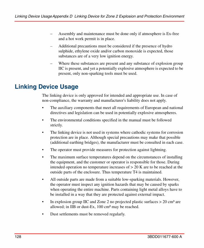
Linking Device UsageAppendix D Linking Device for Zone 2 Explosion and Protection Environment
128 3BDD011677-600 A
– Assembly and maintenance must be done only if atmosphere is Ex-free and a hot work permit is in place.
– Additional precautions must be considered if the presence of hydro sulphide, ethylene oxide and/or carbon monoxide is expected, those substances are of a very low ignition energy.
– Where these substances are present and any substance of explosion group IIC is present, and yet a potentially explosive atmosphere is expected to be present, only non-sparking tools must be used.
Linking Device UsageThe linking device is only approved for intended and appropriate use. In case of non-compliance, the warranty and manufacturer's liability does not apply.
• The auxiliary components that meet all requirements of European and national directives and legislation can be used in potentially explosive atmospheres.
• The environmental conditions specified in the manual must be followed strictly.
• The linking device is not used in systems where cathodic systems for corrosion protection are in place. Although special precautions may make that possible (additional earthing bridges), the manufacturer must be consulted in each case.
• The operator must provide measures for protection against lightning.
• The maximum surface temperatures depend on the circumstances of installing the equipment, and the customer or operator is responsible for those. During intended operation no temperature increases of > 20 K are to be reached at the outside parts of the enclosure. Thus temperature T4 is maintained.
• All outside parts are made from a suitable low-sparking materials. However, the operator must inspect any ignition hazards that may be caused by sparks when operating the entire machine. Parts containing light metal alloys have to be installed in a way that they are protected against external impact.
• In explosion group IIC and Zone 2 no projected plastic surfaces > 20 cm³ are allowed; in IIB or dust-Ex, 100 cm² may be reached.
• Dust settlements must be removed regularly.
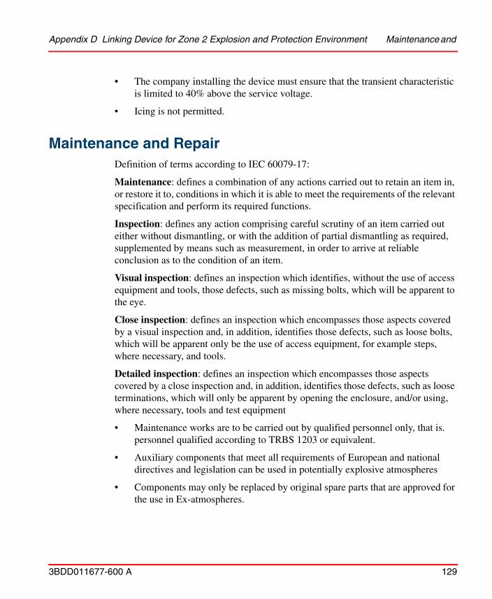
Appendix D Linking Device for Zone 2 Explosion and Protection Environment Maintenance and
3BDD011677-600 A 129
• The company installing the device must ensure that the transient characteristic is limited to 40% above the service voltage.
• Icing is not permitted.
Maintenance and RepairDefinition of terms according to IEC 60079-17:
Maintenance: defines a combination of any actions carried out to retain an item in, or restore it to, conditions in which it is able to meet the requirements of the relevant specification and perform its required functions.
Inspection: defines any action comprising careful scrutiny of an item carried out either without dismantling, or with the addition of partial dismantling as required, supplemented by means such as measurement, in order to arrive at reliable conclusion as to the condition of an item.
Visual inspection: defines an inspection which identifies, without the use of access equipment and tools, those defects, such as missing bolts, which will be apparent to the eye.
Close inspection: defines an inspection which encompasses those aspects covered by a visual inspection and, in addition, identifies those defects, such as loose bolts, which will be apparent only be the use of access equipment, for example steps, where necessary, and tools.
Detailed inspection: defines an inspection which encompasses those aspects covered by a close inspection and, in addition, identifies those defects, such as loose terminations, which will only be apparent by opening the enclosure, and/or using, where necessary, tools and test equipment
• Maintenance works are to be carried out by qualified personnel only, that is. personnel qualified according to TRBS 1203 or equivalent.
• Auxiliary components that meet all requirements of European and national directives and legislation can be used in potentially explosive atmospheres
• Components may only be replaced by original spare parts that are approved for the use in Ex-atmospheres.
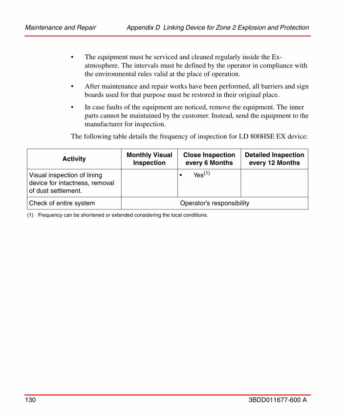
Maintenance and Repair Appendix D Linking Device for Zone 2 Explosion and Protection
130 3BDD011677-600 A
• The equipment must be serviced and cleaned regularly inside the Ex-atmosphere. The intervals must be defined by the operator in compliance with the environmental rules valid at the place of operation.
• After maintenance and repair works have been performed, all barriers and sign boards used for that purpose must be restored in their original place.
• In case faults of the equipment are noticed, remove the equipment. The inner parts cannot be maintained by the customer. Instead, send the equipment to the manufacturer for inspection.
The following table details the frequency of inspection for LD 800HSE EX device:
ActivityMonthly Visual
InspectionClose Inspection every 6 Months
Detailed Inspection every 12 Months
Visual inspection of lining device for intactness, removal of dust settlement.
• Yes(1)
(1) Frequency can be shortened or extended considering the local conditions.
Check of entire system Operator’s responsibility
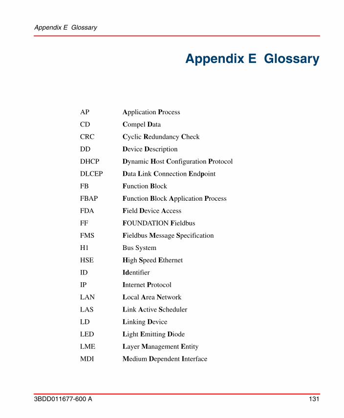
Appendix E Glossary
3BDD011677-600 A 131
Appendix E Glossary
AP Application Process
CD Compel Data
CRC Cyclic Redundancy Check
DD Device Description
DHCP Dynamic Host Configuration Protocol
DLCEP Data Link Connection Endpoint
FB Function Block
FBAP Function Block Application Process
FDA Field Device Access
FF FOUNDATION Fieldbus
FMS Fieldbus Message Specification
H1 Bus System
HSE High Speed Ethernet
ID Identifier
IP Internet Protocol
LAN Local Area Network
LAS Link Active Scheduler
LD Linking Device
LED Light Emitting Diode
LME Layer Management Entity
MDI Medium Dependent Interface

Appendix E Glossary
132 3BDD011677-600 A
NMA Network Management Agent
NMIB Network Management Information Base
OD Object Dictionary
PD Physical Device
RAM Random Access Memory
SM System Management
SMIB System Management Information Base
SMK System Management Kernel
SMKP System Management Kernel Protocol
SNMP Simple Network Management Protocol
SNTP Simple Network Time Protocol
TCP Transmit Control Protocol
TFTP Trivial File Transfer Protocol
UDP User Datagram Protocol
VCR Virtual Communication Relationship
VFD Virtual Field Device
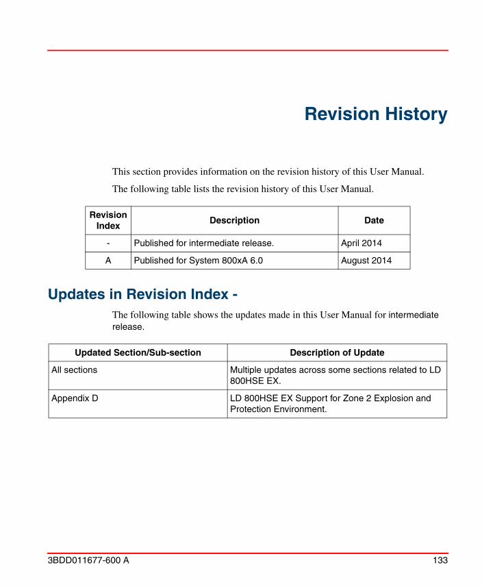
3BDD011677-600 A 133
Revision History
This section provides information on the revision history of this User Manual.
The following table lists the revision history of this User Manual.
Updates in Revision Index -The following table shows the updates made in this User Manual for intermediate release.
Revision Index
Description Date
- Published for intermediate release. April 2014
A Published for System 800xA 6.0 August 2014
Updated Section/Sub-section Description of Update
All sections Multiple updates across some sections related to LD 800HSE EX.
Appendix D LD 800HSE EX Support for Zone 2 Explosion and Protection Environment.
Updates in Revision Index A
134 3BDD011677-600 A
Updates in Revision Index AThe following table shows the updates made in this User Manual for 800xA 6.0 Feature Pack.
Updated Section/Sub-section Description of Update
Section 1 Sample screen shot update to include LD 800HSE EX.


Power and productivityfor a better worldTM
Contact us
Copyright© 2014 ABB.All rights reserved.
3BD
D01
1677
-600
A www.abb.com/800xA
www.abb.com/controlsystems