foundation fieldbus ff01 mk 2 option card installation · pdf filefoundation fieldbus ff01 mk...
TRANSCRIPT

Publication S179E V2.0 Issue 08/05
Foundation Fieldbus FF01 Mk 2 Option Card
Installation Manual

Foundation Fieldbus FF01 Mk 2 Installation manual
2 of 76 Publication S179E V2.0 Issue 08/05
Note 1:
Throughout this manual the Foundation FF01 Mk2 may simply be referred to as the module. Note 2: The information in this manual relates to the following firmware releases
Module Version Network Interface Card Mitsubishi Processor Texas Processor
M1.1 T1.0
Interface Card M207 Note 3: The FF01 Mk2 module described in this manual is suitable for inclusion in Rotork IQ, IQT and Q
actuators.
As we are continually developing our products their design is subject to change without notice. © The contents of this document are copyright and must not be reproduced without the written permission of Rotork Controls Ltd. The name Rotork is a registered trademark Foundation is a registered trademark of the Fieldbus Foundation NI-FBUS is a registered trademark of National Instruments. Windows is a registered trademark of The Microsoft Corporation

Contents
Publication S179E V2.0 Issue 08/05 3 of 76
Contents
Glossary of Terms: .........................................................................................................................5 Abbreviations:.................................................................................................................................6 Supporting Documents:.................................................................................................................6
1 INTRODUCTION................................................................................................ 7 1.1 General ..................................................................................................................................8
2 FOUNDATION FIELDBUS FF01 MK2 MODULE PROPERTIES...................... 9 2.1 Mechanical properties..........................................................................................................9 2.2 Electrical properties ...........................................................................................................10 2.3 Operation and storage .......................................................................................................10
3 FITTING THE FF01 MK2 MODULE................................................................. 11 3.1 Inside an IQ/IQT actuator ...................................................................................................11 3.2 Inside a Q actuator .............................................................................................................12 3.3 Jumper and links functions...............................................................................................13 3.4 Replacing or fitting a Foundation FF01 MK2 module .....................................................14
4 IEC 61158 DATA HIGHWAY AND CONNECTIONS....................................... 17 4.1 Data highway ......................................................................................................................17 4.2 Fieldbus power supply.......................................................................................................18 4.3 Termination network ..........................................................................................................19
5 THE ACTUATOR INPUT AND OUTPUT SIGNALS........................................ 21 5.1 Controls ...............................................................................................................................21
5.1.1 Controls priority ..................................................................................................24 5.1.2 Foundation control using DO blocks only...........................................................25 5.1.3 Foundation control using the AO block only.......................................................26 5.1.4 Foundation control using both DO and AO blocks .............................................26 5.1.5 The IQ ‘S’ contacts (Foundation DO’s) controlled by the DO blocks .................27 5.1.6 Foundation network control disable feature .......................................................27
5.2 Discrete Input status feedback .........................................................................................28 5.2.1 Discrete Inputs from all actuator types ...............................................................29 5.2.2 Discrete Inputs from IQ and IQT actuator ..........................................................31 5.2.3 Discrete Inputs from IQT actuator ......................................................................32 5.2.4 Discrete Inputs reporting the FF01 Mk2 module condition.................................33
5.3 Actuator Analogue Input feedback...................................................................................33
6 FUNCTION BLOCKS ...................................................................................... 35 6.1 Resource Block ..................................................................................................................36

Foundation Fieldbus FF01 Mk 2 Installation manual
4 of 76 Publication S179E V2.0 Issue 08/05
6.2 Transducer Block ...............................................................................................................38 6.2.1 Transducer block parameters.............................................................................39 6.2.2 Changing the settings in the Transducer block. .................................................43 6.2.3 Editing the Foundation specific parameters 1-23 and 96-98..............................44 6.2.4 Editing the actuator setup parameters 50-67 .....................................................45 6.2.5 Editing the control parameters 68-69 .................................................................50
6.3 Analogue Input blocks .......................................................................................................51 6.4 Discrete Input blocks .........................................................................................................51 6.5 Analogue Output block ......................................................................................................53 6.6 Discrete Output blocks ......................................................................................................54
6.6.1 Multiple block – single bit control........................................................................55 6.6.2 Single block – multiple bit control. ......................................................................56
6.7 PID Control block ...............................................................................................................58
7 LINK ACTIVE SCHEDULER ........................................................................... 59 7.1 Creating a schedule ...........................................................................................................60 7.2 Connecting the blocks .......................................................................................................61
8. SETTING UP THE FF01 MK2 MODULE ......................................................... 63 8.1 Setting up an IQ or IQT with the Setting Tool..................................................................63 8.2 Methods...............................................................................................................................64 8.3 Control output function block settings ............................................................................65
8.3.1 Analogue Only control ........................................................................................66 8.3.2 Discrete Only control ..........................................................................................66 8.3.3 Mixed Analogue and Discrete control.................................................................67 8.3.4 Hard wired inputs - Aux Input Function ..............................................................67
8.4 Status feedback function block settings .........................................................................67 8.4.1 Analogue position and torque data.....................................................................68 8.4.2 Discrete Input data .............................................................................................68
8.4 Downloading the settings to the Actuator .......................................................................68 8.5 Default settings...................................................................................................................69
9 THE FF01 MK2 FIRMWARE AND DD FILES ................................................. 71 9.1 Firmware..............................................................................................................................71 9.2 Device Description Files ....................................................................................................71
APPENDIX A – HANDLING FAULT CONDITIONS................................................. 72
APPENDIX B – FUNCTION BLOCK MODE – LO................................................... 73
APPENDIX C – PID APPLICATION ........................................................................ 74

Contents
Publication S179E V2.0 Issue 08/05 5 of 76
Glossary of Terms:
Capabilities File A file describing the communication objects in a fieldbus device. A configuration device can use Device Description (DD) Files and Capabilities Files to configure a fieldbus system without having the fieldbus devices online.
Device Description (DD) A machine-readable description of all the blocks and block parameters of a device.
Fieldbus The digital, two-way, multi-drop communication links. Field Unit The FF01 MK2 card fitted to the actuator. H1 A term used to describe a fieldbus network operating at 31.25
kbit/sec. Interoperability The capability for a device from one manufacturer to interact with that
of another manufacturer, on a fieldbus network, without loss of functionality.
Link Active Scheduler (LAS) One Link Master (LM) device functions as the fieldbus LAS at any one time. The LAS is the Fieldbus device that is currently controlling access to the Fieldbus. A device that is responsible for keeping a link operational. The LAS executes the link schedule, circulates tokens, distributes time, and probes for new devices.
Schedules Communication that occurs at the same time during each control cycle. The schedule defines when Function Blocks (FB’s) execute and when data and status is published on the bus.
Segment A Foundation Fieldbus network is made up of devices connected by a serial bus. This serial bus is called a segment (also known as a link). A section of an H1 fieldbus that is terminated in its characteristic impedance. Segments can be linked by Repeaters to form a longer H1 fieldbus. Each Segment can include up to 32 H1 devices.
Standard Function Block (FB) A named block consisting of one or more input, output, and contained parameters. These are built into fieldbus devices to achieve the desired control functionality. The FF01 MK2 has Analogue Input (AI), Analogue Output (AO), Digital Input (DI), Digital Output (DO) and PID control.
Transducer Block (TB) A block that is an interface to the physical, sensing hardware in the device. It also performs the digitizing, filtering, and scaling conversions needed to present input data to function blocks, and converts output data from function blocks. The block decouples the Function Blocks (FB’s) from the local input/output (I/O) functions required to read the limit switches and command the actuator to move.
Virtual Communication Relationship (VCR). Preconfigured or negotiated connections between virtual field devices on a network.
Virtual Field Device (VFD) The virtual field device is a model for remotely viewing data described in the object dictionary. The services provided by the Fieldbus Messaging Specification allow you to read and write information about the object dictionary, read and write the data variables described in the object dictionary, and perform other activities such as uploading/downloading data and invoking programs inside a device. A model for remotely viewing data described in the object dictionary.

Foundation Fieldbus FF01 Mk 2 Installation manual
6 of 76 Publication S179E V2.0 Issue 08/05
Abbreviations:
Comms Communications FB Function Block FF Foundation Fieldbus FU Field Unit LAS Link Active Scheduler RAM Random Access Memory ROM Read Only Memory SW Software TB Transducer Block Supporting Documents:
Available from the Fieldbus Foundation, Austin Texas
Technical Overview of Foundation Fieldbus FD-003 (all parts). Wiring and Installation 31.25 kbit/s, AG-140

Introduction
Publication S179E V2.0 Issue 08/05 7 of 76
1 INTRODUCTION
The Rotork FF01 Mk2 Foundation Fieldbus Module conforms to the open fieldbus standard IEC 61158. It is suitable for use on an H1 highway and uses two copper wires for connection to the highway. It is necessary to have a suitable power supply and termination filter on the highway for the FF01 Mk2 to function. The current version of the FF01 Mk2 card assembly may be fitted into the IQ, IQT or Q actuators. The FF01 Mk2 module is an integral part of the actuator in which it is housed. The module is fitted within the main double sealed electrical housing. This electrical housing need never be opened once the actuator leaves the assembly plant. All adjustments to the settings for the FF01 Mk2 module may be made via Foundation data highway using a suitable network configuration tool. There is no external marking on the actuator to show the FF01 Mk2 serial number since the whole module may be replaced if it should fail. The FF01 Mk2 circuits do not impinge on the actuator control electronics; the actuator itself remains fully self-protecting. The module performs the tasks of IEC 61158 interface, actuator data collection and the issuing of actuator commands. The FF01 MK2 may command the actuator into which it is fitted to open, stop, close, perform an ESD operation or move to a set position. Commands to the module come from the network and may be generated in another actuator or device on the network using peer to peer, publisher/subscriber communication. Additionally, digital and analogue status information relating to the actuator is published for the other devices to read.
Fig 1: The Foundation Fieldbus FF01 Mk2 Module Actuator Compatibility
Terminal Cover
Local Controls
Handwheel
Electrical Compartment
Motor
Terminal Cover
Electrical Compartment
Local Controls
Handwheel
Electrical Compartment
Terminal Cover
IQ range
IQT range
Q range
Handwheel
Local Controls

Foundation Fieldbus FF01 Mk 2 Installation manual
8 of 76 Publication S179E V2.0 Issue 08/05
1.1 General
The FF01 Mk2 module is capable of performing the following functions –
a) Link Master b) Link Active Scheduler
The in-built function blocks vary in availability between the different actuator types. The input and output blocks are used to link to the transducer block and tie to the available actuator functions. For example the AI block associated with actuator torque measurement is not available in the Q actuator. The following table lists the function blocks and their related availability in each actuator type.
Function Block Type IQ actuator IQT actuator Q actuator Resource Block System information Transducer Block Device configuration Digital Inputs DI 1 (variable) DI 2 (variable)
DI 3 (variable) DI 4 (variable)
DI 5 (variable)
Digital Outputs DO 1 Open or Multistate DO 2 Close or Multistate DO 3 ESD or Multistate DO 4 Multistate
Analogue Inputs
AI 1 Position AI 2 Torque (IQ and IQT)
Analogue Output
AO 1 Desired position
Controller PID (3 term controller)

FF01 Module Properties
Publication S179E V2.0 Issue 08/05 9 of 76
Interface Card
2 FOUNDATION FIELDBUS FF01 MK2 MODULE PROPERTIES
2.1 Mechanical properties
The FF01 MK2 module comprises two printed circuit boards that fit together and the assembly is fitted inside the actuator electrical housing.
Network Interface Card This carries the Foundation fieldbus highway connections and the processor handling the data highway communication and function blocks.
Interface Card The larger motherboard is profiled and assembled to fit an IQ actuator
as shown, or Q actuator. It carries the processor for collecting the data from the actuator main board and passing this data to the Bus card.
The primary connection to the actuator circuits is by a multi-pin connector on the Interface Card that, due to its physical shape may only be fitted in the correct polarisation. Internal wiring harnesses connect to the Interface card for other signals and options within the actuator. The Network Interface Card carries the Foundation Fieldbus connector, this connects to the wiring harness routed to the terminal compartment of the actuator. Power for the Network Interface Card is taken from the Foundation Fieldbus highway whilst the Interface card is powered from within the actuator. All the connectors are polarised to prevent incorrect insertion.
Fig 2: The FF01 Mk2 module showing the NIC and Interface Card (IQ actuator)
Network Interface Card

Foundation Fieldbus FF01 Mk 2 Installation manual
10 of 76 Publication S179E V2.0 Issue 08/05
2.2 Electrical properties
The FF01 Mk2 module Interface board connects directly to the main board of the actuator. The FF01 Mk2 does not sit in the main control path for the actuator and does not affect the actuator control integrity. Internally stored programs control the three processors on the module. The Network Interface Card processor software may be updated by connecting a suitable test cable and loading the new code directly. The software for the Interface card is within its processor and may be updated by replacement of the processor chip itself. The Foundation Fieldbus system allows all settings for the data highway and module communication functions to be held in non-volatile memory on the Network Interface Card. The Foundation Fieldbus data highway connection is fully isolated from the actuator electronics and the Interface card. 2.3 Operation and storage
The Module is designed to be stored in the actuator and operated within the same environment as the actuator. The constraints are:
Operating temperature: -40oC to +70oC Storage temperature: -50oC to +85o C Relative Humidity: 5% to 95% (<50oC) non-condensing

Fitting theFF01 Modulee
Publication S179E V2.0 Issue 08/05 11 of 76
3 FITTING THE FF01 MK2 MODULE
3.1 Inside an IQ/IQT actuator
The FF01 Mk2 is suitable fro fitting into IQ2 M2 actuators with 3000 or 5000 series wiring diagrams and IQT with 6000 or 7000 series wiring diagrams. The connection and fitting in an IQT is similar to that for an IQ and the following information effectively relates to both actuator types. The FF01 MK2 module is fitted in the first option board slot inside the IQ or IQT electrical housing using connection SK1. The Interface card must be correctly profiled and loaded with the appropriate connectors to match the IQ or IQT actuator. The illustration (Fig 3) shows the IQ/IQT version of the FF01 Mk2. The links are shown in their normal position.
With the IQ/IQT actuator the remote inputs are always present (they are conditioned by the FF01 Mk2) and there is an option to include Digital Outputs from relay contacts. If the FF01 Mk2 is required to operate the 4 digital outputs that can be controlled from the card then the Extra Relay Indication card associated with these outputs must be fitted into the actuator. The following table describes the wiring harnesses and their function in the IQ and IQT actuator.
FF01 Socket Wiring Harness 3000/6000 Series WD
3300/6300 Series WD
SK3 Foundation Fieldbus Data Highway Yes Yes SK5 Main Board connections Yes Yes SK7 Remote relay board connections (Optional) No Yes SK8 Data logger connections to main board Yes Yes
To restore the card to its factory defaults for the actuator associated parameter settings, LK1 on the Interface card should be fitted and the power cycled (see Fig. 7). The Foundation highway must be disconnected when restoring these defaults
Fig 3: The FF01 Mk2 module profiled for the IQ or IQT actuator
SK5 SK7
EPROM
SK
1
SK8
LK1
- +
OFF
OFF
SK3

Foundation Fieldbus FF01 Mk 2 Installation manual
12 of 76 Publication S179E V2.0 Issue 08/05
3.2 Inside a Q actuator
The FF01 MK2 is fitted in the option board position in this actuator. Only one option board may be fitted at any one time. The necessary internal components must also be present; in this case a potentiometer must be fitted to the actuator. The necessary internal components must also be present; in this case a potentiometer and auxiliary limit switches at end of travel must be fitted to the actuator. The Interface card must be correctly profiled and loaded with the appropriate connectors to match the Q actuator. The illustration (Fig 4) shows the Q version of the FF01 Mk2. The links are shown in their normal position.
Digital Outputs from relay contacts are not supported from the Q actuator, nor is the ability to report the status of the remote control inputs as Digital Inputs. The following table shows the wiring harnesses that must be fitted and the function of each loom for the Q range actuator. FF01 Socket Wiring Harness Q range WD SK3 Foundation Fieldbus Data Highway Yes SK9 Limit switches Yes SK11 Potentiometer Yes
In a Q actuator there is a direct connection from PL2 on the Interface Card to SK5 of the actuator main board. To restore the card to its factory defaults for the actuator associated parameter settings, LK1 on the Interface card should be fitted and the power cycled (see Fig. 7). The Foundation highway must be disconnected when restoring these defaults
Fig 4: The FF01Mk2 module profiled for the and Q actuator
EPROM
SK9 SK11
LK1
SK
1 - +
OFF
OFF
SK3

Fitting the FF01 Module
Publication S179E V2.0 Issue 08/05 13 of 76
3.3 Jumper and links functions
The Network Interface Card includes 2 LED indicators and 3 jumpers. The position of these jumpers should not normally require alteration from the factory default positions. The illustration shows the default positions. The LED’s can be used to help with system diagnostics in some cases. The function of each jumper and LED is as follows.
JP1, (Simulation) In simulation mode the user is permitted to write to primary input/output actuator variables through the status and value attributes normally written to by the transducer block. With JP1 ‘ON’ a function block may have its simulation ‘active’ parameter enabled. When JP1 is ‘OFF’ the primary actuator variables ore not write enabled. The normal position is Off.
- +
OFF
OFF
SK3
JP 3
JP 2JP 1
LED 1
LED 2
Fig 5: Network Interface Card - Jumper and LED functions.
Fig 6: Simulate has been activated in the AI function block.

Foundation Fieldbus FF01 Mk 2 Installation manual
14 of 76 Publication S179E V2.0 Issue 08/05
JP2, Hard Write Lock A setting can be made in the ‘FEATURE_SEL’ parameter of the Resource block which prevents the writing/changing of all configuration parameters in the FF01 MK2. If the FEATURE_SEL is set to ‘Hard W Lock’, the jumper function becomes write protect ‘On’ and ‘Off’. (See section 6.1 Resource Block). The normal position is Off.
JP3, Power On When in the ‘On’ position the card will draw its power from the
Fieldbus connection. In the ‘Off’ position power must be supplied externally. Used, for example, during firmware programming. The normal position is Off.
LED 1 Indicates the Fieldbus Network Interface Card is communicating with
the actuator Interface Card (base-board).
LED 2 Indicates there is an active connection to the fieldbus – (flashing). 3.4 Replacing or fitting a Foundation FF01 MK2 module
The FF01 MK2 module should be replaced or fitted only in a suitable environment. The actuator must be made electrically safe before opening the covers; in the case of an IQ/IQT it is advisable to disconnect the internal battery. The electrical housing cover should be removed and the existing FF01 MK2 carefully unplugged from its main connector. Once removed from the main connector the wiring loom connectors should be removed. The replacement board is fitted in the reverse order to removal. The wiring harnesses are polarised so that only the correct one will fit its mating part on the circuit board.
If the operation is to fit a module for the first time then the necessary wiring looms must be added to the internal wiring harness of the actuator. The actuator wiring diagram shows the connectors and harnesses used. The wiring harnesses are fitted inside the actuator before attempting to fit the FF01 MK2 module. Once the looms are in place connect them to the module, then fit the module to the main board connector.
Fig 7: The FF01 Mk2 Interface card showing link used to set the card to default settings.
SK5 SK7
EPROM
SK
1
SK8
LK1
LK1

Fitting the FF01 Module
Publication S179E V2.0 Issue 08/05 15 of 76
Once the card is fitted the actuator should be re-assembled and, in the case of the IQ or IQT, the battery replaced. The FF01 Mk2 must not be split between the Network Interface Card and the Interface card. Only complete assemblies should be fitted or exchanged. If required the firmware in the Network Interface Card can be updated using tools available from Rotork (see section 9 the FF01 MK2 Firmware). If at any time it is necessary to reset the card to its supplied default values the Network Interface card should be removed and a shorting link applied to LK1. The Interface card must then be put back in the actuator and the mains power cycled. The Network Interface card must then be re-assembled onto the interface board and the pair refitted into the actuator. LK1 is usually used as a mechanical connection link between the top and bottom boards.

Foundation Fieldbus FF01 Mk 2 Installation manual
16 of 76 Publication S179E V2.0 Issue 08/05
(This page is intentionally blank.)

IEC 61158 Data Highway
Publication S179E V2.0 Issue 08/05 17 of 76
4 IEC 61158 DATA HIGHWAY AND CONNECTIONS
4.1 Data highway
The Foundation Fieldbus network is based on the IEC 61158 data highway using copper conductors. The network also carries the power used to supply each node on the network. In the case of the FF01 MK2 device the Bus board is powered from the fieldbus network. Only two wires are used for the data highway and these carry both the data signal and the module power. The actuator interface card is powered from the actuator itself and the assembly can only report data when both the data bus and actuator are powered up.
The data highway must be terminated with proper balancing devices at either end. The highway can use spur or stub connections to the devices but it is recommended to keep any stub lengths to a minimum for successful operation. The length of the highway and number of devices connected will vary from project to project. The standard permits up to 32 devices before a repeater in the highway must be used. Similarly the standard calls for a maximum segment length of 1900 metres before a repeater must be used. On a 1900 metre highway the stipulated maximum length for a stub with one actuator is 120 metres. The data highway cable type is given by the Foundation as ‘type A’, typically Belden 3076F.
Cable Specification Type A Cable (e.g. Belden 3076F) Type 2 cores, twisted pair plus overall screen Shielding Minimum 90% copper shielding, braid or foil Size 18 AWG (0.8 mm2) Resistance 24 ohms/km max Nominal Capacitance 80 pf/m
Fig 8: Typical Foundation Data Highway
2 wire pair
Terminator
FieldbusPowerSupply
+
-
FoundationInterface T
T

Foundation Fieldbus FF01 Mk 2 Installation manual
18 of 76 Publication S179E V2.0 Issue 08/05
4.2 Fieldbus power supply
The FF01 MK2 module takes power from the Foundation fieldbus data highway. The Bus board is powered by the fieldbus so that the internal function blocks are available for control connection between devices even when the actuator has no power. The power is taken from a special DC power supply connected onto the network through a suitable filter. The power consumption of each Rotork node on the network is 18mA (nominal) and the absolute minimum voltage at the actuator terminals is 9 volts. The power supply has to contain an inductive network to prevent attenuation of the fieldbus signal by the low impedance of the power supply itself. The inductive network in the power pack makes sure that its equivalent impedance is quite high at the 31.25 kbits/sec frequency whilst still allowing a DC current to be drawn for the line powered devices. Since each node on the fieldbus consumes power from the DC supply great care must be taken in the design of the installation. The design must ensure that the volt drop from the power pack to the actuator still leaves at least 9V (absolute minimum) for the round card and ideally at least 10 Volts. The actuators can withstand a maximum voltage of 32V from the power pack and since the current consumption is virtually constant a simple Ohms law calculation can be used to determine the potential at each point in the network. On power up the inrush current of the round card will exceed the nominal by a factor 3. The Foundation fieldbus wiring guide (AG -140) provides examples of how to calculate the voltage at each point.
Example of voltage drop calculation: Assume the cable is Type A (24 ohm per km per conductor), the resistance of each 1000 metre pair is 24x2 = 48 ohms per km. The current drawn by each node A1 to A6 is 20 mA. Voltage drop Power supply to A1 = current x resistance
Fig 9: Calculating the Voltage Drop
FieldbusPowerSupply
+-
T
T
A 1
A 2
A 3 A 5
A 4
I
800 m 200 m 200 m 200 m 200 m 200 mA 6

IEC 61158 Data Highway
Publication S179E V2.0 Issue 08/05 19 of 76
= (6 x 0.020) x (0.8 x 48) = 4.6 volts Voltage drop A1 to A2 = (5 x 0.020) x (0.2 x 48) = 0.96 volts Voltage drop A2 to A3 = (4 x 0.020) x (0.2 x 48) = 0.768 volts Voltage drop A3 to A4 = (3 x 0.020) x (0.2 x 48) = 0.576volts Voltage drop A4 to A5 = (2 x 0.020) x (0.2 x 48) = 0.384volts Voltage drop A5 to A6 = (1 x 0.020) x (0.2 x 48) = 0.192volts Total system volt drop = 4.6 + 0.96 + 0.768 + 0.576 + 0.384 + 0.192 = 7.48 volts If the power supply is a 24 V unit, then the voltage at actuator A6 will be (24 – 7.48) = 16.52 volts which is within the specified minimum.
4.3 Termination network
Each highway must be terminated correctly at the two ends of the data highway. The terminator comprises at least one resistor and capacitor in series and they provide a characteristic impedance of 100 ohm at 39 kHz. They need not be placed on the absolute ends of the highway but should be on the ends of the main trunk section. There are no termination facilities inside the actuator itself.
Fig 10: Voltage Drop Example
FieldbusPowerSupply
+-
T
T
A 1
A 2
A 3 A 5
A 4
I
4.6 V 0.96 V 0. 768 V 0.576 V 0.384 V 0.192 VA 6
24 V 16.52 V

Foundation Fieldbus FF01 Mk 2 Installation manual
20 of 76 Publication S179E V2.0 Issue 08/05
(This page intentionally left blank.)

Actuator Input Output Signals
Publication S179E V2.0 Issue 08/05 21 of 76
5 THE ACTUATOR INPUT AND OUTPUT SIGNALS
The FF01 MK2 module provides feedback data about its status and that of the actuator to the Foundation highway. This data is contained in the Transducer function block and is fully listed in the section on Function Blocks. The actuator is normally controlled by signals from the Foundation highway connecting to the Output blocks and the Transducer block. There are local controls on the actuator itself and there is the possibility to wire in direct contacts to control the movement. This section explains the primary data available and the meaning of the signals generated by the actuator.
Input signals are those returned by the actuator to the network about the status of the actuator and valve whilst output signals are those used to command the actuator to move or operate its internal relays. An actuator control signal such as a command to open is an output, whilst a reported status such as open limit switch reached is a feedback input. 5.1 Controls
The FF01 Mk2 Module can be used to control the actuator and position the valve. The valve may be moved fully closed, fully open or to an intermediate position. Additionally the actuator can make the valve adopt an Emergency Shut Down position or the actuator can be prevented from moving by the presence of an Interlocking signal from another device on the plant. The actuator may also be operated from its local controls or by hard wired direct contact inputs (in the case of the IQ and IQT the Auxiliary Input Mask must be correctly set).
Fig 11: Actuator and FF01 Mk2 Block Diagram
5x DI
4 x DO
2 x AI
1 x AO
PID
Transducer
ResourceD
ata
Hig
hway
FF-01 Mk2 module
Dat
a Li
nk L
ayer
Fiel
dbus
Acc
ess
Sub
laye
rFi
eldb
us M
essa
ge S
peci
ficat
ion
InterfaceBoard
LocalControls
Hard WiredRemote Controls
ActuatorMain Board
Actuator
Motor andStarter
Controls

Foundation Fieldbus FF01 Mk 2 Installation manual
22 of 76 Publication S179E V2.0 Issue 08/05
As well as controlling the actuator the FF01 Mk2 can also be used to operate 4 discrete output relays when fitted to an IQ/IQT actuator with the relay card fitted. The control commands have three potential sources:
Foundation Fieldbus generated commands Actuator Local Controls Direct contact input controls
The full list of commands is shown in the table. The actuator types show whether the command is applicable to that actuator type.
Command IQ actuator IQT actuator Q actuator Foundation Network
Open Close Stop Emergency Shut Down Analogue Position Demand Partial Stroke Relay output DO-1 1 1 Relay output DO-2 1 1 Relay output DO-3 1 1 Relay output DO-4 1 1
Local Actuator Controls Open Close Stop
Direct Hard Wired Inputs Open 2 Close 2 Stop/Maintain 2 Emergency Shut Down/Network disable 23 Open Interlock (active prevents opening) Close Interlock (active prevents closing)
Note: 1 – Requires Extra Relay Indication board to be fitted 2 – Push to Run action only. Maintained action not available if analogue positioning is
used 3 – Network Disable not available on Q range actuator

Actuator Input Output Signals
Publication S179E V2.0 Issue 08/05 23 of 76
The Foundation Fieldbus commands operate on the Transducer block through Digital Output (DO) blocks that are already connected in the default configuration. The network commands will operate the actuator provided –
• Local/Local Stop/Remote selector is in ‘Remote’, • On IQ or IQT actuators, Foundation commands are not inhibited by the ‘Inhibit/DI-4’ input
parameter setting and DI-4 condition • No interlock is active on IQ or IQT actuators. • There is no standing hard wired control input active • No alarm condition prevents it from moving
Open A digital command to cause the actuator to open to the fully open position as indicated by the Open limit switch. Under correct operation the actuator stops either when the open limit switch is reached, when the torque exceeds the value set and the open limit switch has been reached, or a new command is sent over the network.
Close A digital command to cause the actuator to close to the fully closed
position as indicated by the Close limit switch. Under correct operation the actuator stops either when the close limit switch is reached, when the torque exceeds the value set and the close limit switch has been reached, or a new command is sent over the network.
Stop With no other command present this digital command causes an
actuator motor that is running to stop.
Emergency Shut Down A digital command that causes the actuator to drive to its Emergency position. There are settings within the actuator to determine if this is a closed, open or stay put action.
Analogue Position Demand This function is only available over the Foundation
network. To initiate, the Position Control bit in a DO must be set to 1 and all other actuator control bits must be set to 0. This enables the AO block function and the actuator will then move to the position set by the value in the AO block output parameter (range 0-100%, resolution 1%). If the value of the AO block output is changed the actuator will move to the new value. Provided limited range positioning is not invoked the values 0% and 100% written to the AO output parameter produce a special case output where the command is revised so as to fully close the valve to its tight shut off position (0%) and fully open the valve (100%).
Note: Many IQ multi-turn actuators are set to open until the open limit switch is reached and, close until the closing on torque switch trips, but it is dependant on the type of valve. The IQT and Q normally operate 90-degree valves, use stop bolts on the actuator or gearbox, and stop when these are reached. The control room indication is always taken from the end of travel limit switch settings

Foundation Fieldbus FF01 Mk 2 Installation manual
24 of 76 Publication S179E V2.0 Issue 08/05
Partial Stroke The actuator will move the valve to an intermediate position and back to the start position provided it is at the correct end of travel position when the command is issued. The end to start from and the amount of travel are selected by parameters in the transducer block.
Relay Output DO-1 to DO-4 These 4 commands are used to energise and de-
energise the internal relays on the additional relay board in an IQ or IQT actuator. (These outputs are referred to as S5-S8 in the standard actuator documentation when there is no FF01 Mk2 Module in the actuator.) The resulting outputs can be used for operating other equipment such as a pump or indication light. The IQ/IQT actuator is not able to control these relays directly from the main board when the FF01 Mk2 is fitted, they may only be controlled by the DO blocks. They will maintain their last state if power is removed from the actuator. On restoration of power the relays will be reset to their de-energised condition.
Hard Wired Open and Close These commands operate the actuator in the same way
as the open and close commands sent over the Foundation highway.
Hard Wired Stop The hard wired stop input acts as a change of state input. If the actuator is moving, opening the Stop input will stop the actuator. If the Stop input is already open and a Foundation DO command is sent to the actuator, the Foundation command will be initiated. To stop the actuator the hard wired input must be closed and opened again.
Hard Wired ESD (Network Disable) The hard wired ESD may be set to causes the
actuator to drive to its Emergency position. Alternately the input can be used to disable Foundation network control. The function of the input is determined by a parameter in the transducer block.
5.1.1 Controls priority
Since there are three potential sources for control inputs the actuator and FF01 MK2 card assigns a priority for those occasions when two or more commands are applied simultaneously. Local controls go direct to the main board and override any Foundation controls and any hard-wired controls except hard wired ESD. An actuator that has Local selected cannot be controlled over the Foundation network. In addition, for the IQ and IQT actuator, the remote control hard wired inputs can be used as discrete input signals, to report the status of other devices or as control inputs. The associated Auxiliary Input Mask parameter must be set for the IQ or IQT to select the required function. When selected for control the hard-wired inputs take priority over the Foundation controls, but are subordinate to the local controls (except for ESD). If there is a Foundation command still present when a Local or Hard-wired command is removed the Foundation command will re-assert itself. In the case of the hard wired input for ESD this can be configured either as an ESD/DI-4 signal or as a ‘Foundation Command Inhibit’ to prevent network control signals from moving the actuator.

Actuator Input Output Signals
Publication S179E V2.0 Issue 08/05 25 of 76
High Priority Low Priority
Local Stop Local Close Hard Wired Close Foundation Close Local Open Hard Wired Open Foundation Open Hard Wired ESD Hard Wired Stop Foundation Stop Foundation ESD Foundation Position Foundation Part Stroke
Mechanically interlocked to prevent both at the same time The IQ/IQT can be set so that Local Stop has a higher priority than ESD Only one Foundation command should be applied at a time If a Foundation command is applied whilst Hard Wired Stop is present, stop is cancelled
Fig 12: IQ and IQT Controls Priorities In the case of the Q actuator the control selection is slightly different because the actuator uses a different control circuit. The Local Controls have a higher priority than hard wired or Foundation controls and the hard wired and Foundation controls share the same priority level
If the Stop/Maintain hard wired input is closed (to provide maintained action on the other contact inputs to the actuator) then position control via Foundation cannot be used.
The recommended connection is to use only an open and close buttons or contacts and ‘push to run’ mode where the actuator only moves whilst the contact is closed.
If a Foundation and hard wired input are both present the control priority is set by the actuator priority setting
High Priority Low Priority
Local Stop Local Close Hard Wired Close Local Open Hard Wired Open Hard Wired ESD Foundation Close Hard Wired Stop/Maintain Foundation ESD Foundation Open Foundation Position Foundation Stop
Mechanically interlocked to prevent both at the same time The action depends on the Actuator Control Priority setting Only one Profibus command is permitted at a time, A Foundation Position command must not be applied whilst Hard Wired Maintain is
present A Foundation Stop command is not possible if Hard Wired Maintain is present
Fig 13: Q Controls Priorities 5.1.2 Foundation control using DO blocks only
Discrete action control is achieved using the DO blocks in the FF01 Mk2 module. Each DO block output has a value between 0 and 255. If the host DCS system uses its ‘Boolean Fan In’ function all the discrete controls can be achieved using one (or sometimes two) DO blocks. The selected block is put in service and the appropriate value sent to its output. Only one value is permitted at a time in each block. If Boolean functions are not available then several blocks may need to be used to achieve the desired control actions.
Foundation Fieldbus FF01 Mk 2 Installation manual
26 of 76 Publication S179E V2.0 Issue 08/05
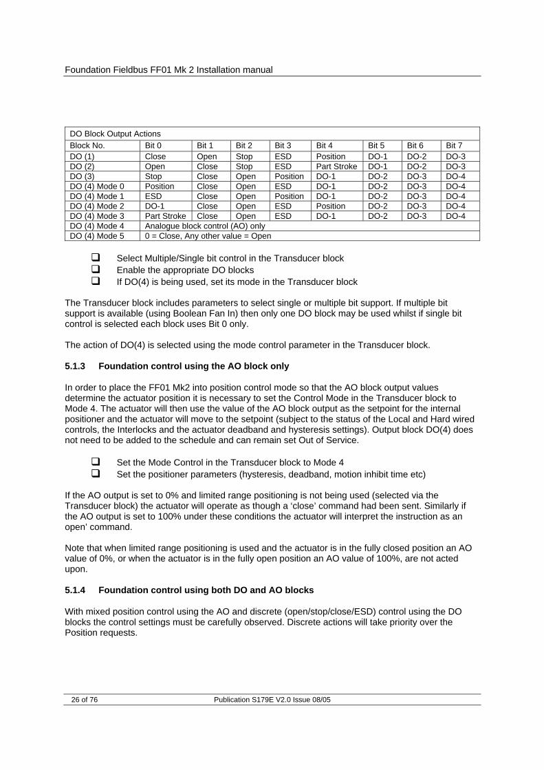
DO Block Output Actions Block No. Bit 0 Bit 1 Bit 2 Bit 3 Bit 4 Bit 5 Bit 6 Bit 7 DO (1) Close Open Stop ESD Position DO-1 DO-2 DO-3 DO (2) Open Close Stop ESD Part Stroke DO-1 DO-2 DO-3 DO (3) Stop Close Open Position DO-1 DO-2 DO-3 DO-4 DO (4) Mode 0 Position Close Open ESD DO-1 DO-2 DO-3 DO-4 DO (4) Mode 1 ESD Close Open Position DO-1 DO-2 DO-3 DO-4 DO (4) Mode 2 DO-1 Close Open ESD Position DO-2 DO-3 DO-4 DO (4) Mode 3 Part Stroke Close Open ESD DO-1 DO-2 DO-3 DO-4 DO (4) Mode 4 Analogue block control (AO) only DO (4) Mode 5 0 = Close, Any other value = Open
Select Multiple/Single bit control in the Transducer block Enable the appropriate DO blocks If DO(4) is being used, set its mode in the Transducer block
The Transducer block includes parameters to select single or multiple bit support. If multiple bit support is available (using Boolean Fan In) then only one DO block may be used whilst if single bit control is selected each block uses Bit 0 only. The action of DO(4) is selected using the mode control parameter in the Transducer block. 5.1.3 Foundation control using the AO block only
In order to place the FF01 Mk2 into position control mode so that the AO block output values determine the actuator position it is necessary to set the Control Mode in the Transducer block to Mode 4. The actuator will then use the value of the AO block output as the setpoint for the internal positioner and the actuator will move to the setpoint (subject to the status of the Local and Hard wired controls, the Interlocks and the actuator deadband and hysteresis settings). Output block DO(4) does not need to be added to the schedule and can remain set Out of Service.
Set the Mode Control in the Transducer block to Mode 4 Set the positioner parameters (hysteresis, deadband, motion inhibit time etc)
If the AO output is set to 0% and limited range positioning is not being used (selected via the Transducer block) the actuator will operate as though a ‘close’ command had been sent. Similarly if the AO output is set to 100% under these conditions the actuator will interpret the instruction as an open’ command. Note that when limited range positioning is used and the actuator is in the fully closed position an AO value of 0%, or when the actuator is in the fully open position an AO value of 100%, are not acted upon. 5.1.4 Foundation control using both DO and AO blocks
With mixed position control using the AO and discrete (open/stop/close/ESD) control using the DO blocks the control settings must be carefully observed. Discrete actions will take priority over the Position requests.

Actuator Input Output Signals
Publication S179E V2.0 Issue 08/05 27 of 76
The single /multiple bit control option for the discrete controls has to be determined. When Boolean Fan In is available, multiple bit control is set and a single DO block is used for the open/stop/close discrete control actions. The DO block chosen must also include a condition to select Position Control. With single bit control each discrete action requires a DO block to be enabled and the Position option is in DO(4) which must be set to Mode 0. When the AO value is to be adopted for the valve position the control scheme must select the DO block to be in its Position value. With multiple blocks DO(4) must be set to ‘1’, all the others being ‘0’. As soon as the discrete control changes to ‘Position’ the AO output value becomes the desired actuator position and the position controller will move the valve.
DO control values of Open/Stop/Close/ESD have priority over the AO value The DO value must equal ‘Position Control’ for the AO value to become active
The position controller will be subject to the considerations mentioned in 5.1.3 with regard to 0% and 100% values. 5.1.5 The IQ ‘S’ contacts (Foundation DO’s) controlled by the DO blocks
The IQ/IQT actuator has four ‘S’ contact outputs that may be configured to report the status of the actuator with signals such as Open Limit, Closed Limit etc. These are identified as S1 to S4. In addition an optional additional relay board can be fitted with four more relays. The status of these relays is then adjusted by Foundation DO block commands on outputs DO-1 to DO-4. Setting the appropriate DO block output to the value corresponding to the relay will energises the relay whilst the output from the DO is present. Setting a different value will de-energise the relay. Note that these
relays are latching and, if energised, will not change state when the actuator power is removed. On restoration of power the relays will be reset to their de-energised condition. 5.1.6 Foundation network control disable feature
It is possible to set the IQ or IQT ESD/DI-4 input so that the IQ/IQT actuator ignores open, stop, close, ESD, Partial Stroke and position control signals sent over the Foundation network. If the DI4 ESD / Net Disable parameter in the Transducer block is set to ‘1’ then when the ESD input is connection is made (i.e. 24 volts applied to ESD), Foundation control is not allowed. This feature is independent of the Auxiliary mask setting. When the DI4 ESD / Net Disable parameter is set to ‘1’, no ESD will be available. This feature is not included in a standard Q range actuator.
Fig 14: IQ and IQT relay outputs DO-1 to DO-4
S1 - S4Actuator
Main Board
IQ or IQT with Additional Relay Output board fitted
DO-1 to DO-4Output Board
FF01

Foundation Fieldbus FF01 Mk 2 Installation manual
28 of 76 Publication S179E V2.0 Issue 08/05
5.2 Discrete Input status feedback
The FF01 Mk2 module has DI (Discrete Input) function blocks that maybe used to report the valve and actuator status over the network. The conventional contact indications are also available from the actuator limit switches and indication contacts. Each DI block output has a value between 0 and 255. If the host DCS system uses it’s ‘Boolean Fan Out’ function the returned value may be decoded into 8 individual bits where each bit represents a single piece of feedback data. If the DCS does not have this facility then the state of the first bit in each DI will be represented by 0 = not true and 1 = true. The complete list of DI’s and the function of the individual bits is indicated in section on DI blocks. The table below indicates which signals are available from each actuator type.
Function Block Number/Bit Number Status Feedback IQ actuator
IQT actuator
Q actuator
DI 1/0 DI2/1 Close Limit DI1/1 DI2/0 Open Limit DI1/2 DI5/0 Actuator Moving DI1/3 DI2/3 Running Closed DI1/4 DI2/2 Running Open DI1/5 DI3/0 Remote selected DI1/6 DI3/1 Local Stop selected DI1/7 DI3/2 Local selected DI2/4 Not in Remote DI2/5 DI4/0 General Alarm DI2/6 Valve Obstructed DI2/7 Valve Jammed DI3/3 Moving Inhibited DI3/4 DI5/5 Open Interlock active input DI3/5 DI5/6 Close Interlock active input DI3/6 Position Control Enabled DI3/7 Slow Mode DI4/1 Thermostat Tripped DI4/2 Monitor Relay DI4/3 Valve Obstructed/jammed DI4/4 Part Stroke Error DI4/5 Valve Moving by Hand DI4/6 Battery Low DI4/7 Watchdog Recovery DI5/1 DI –1 DI5/2 DI –2 DI5/3 DI –3 DI5/4 DI –4 DI5/7 Partial Stroke in Progress Note: 1 – This bit is reported when within the slow mode band, but does not affect the actuator.

Actuator Input Output Signals
Publication S179E V2.0 Issue 08/05 29 of 76
5.2.1 Discrete Inputs from all actuator types
Close Limit This data bit indicates that the actuator has reached the closed position. The limit switch should be set slightly within the actual valve stroke to allow for torque seating or overshoot on closing without damaging the valve. The data bit will remain true (1) even if the position is passed through or exceeded.
Open Limit This data bit indicates that the actuator has reached the open position.
The limit switch should be set slightly within the actual valve stroke to allow for torque seating or overshoot on opening without damaging the valve. The data bit will remain true (1) even if the position is passed through or exceeded.
Actuator Moving Whenever the actuator position is changing due to the motor running
or in the case of the IQ or IQT if the output drive is moving, this bit will be set true (1).
Running Closed Whenever the actuator motor contactor used to drive the actuator in
the closing direction is energised this bit will be true (1).
Running Open Whenever the actuator motor contactor used to drive the actuator in the opening direction is energised this bit will be true (1).
Remote Selected This bit is true (1) when the actuator three position remote/local
stop/local selector is in the Remote position. The selector must be in this position for Foundation control to be permitted.
Local Stop The actuator three position selector passes from Local to Remote or
Remote to Local through the Local Stop position. The switch can also be placed in Local Stop. When the switch is in the Local Stop position this bit will be true (1). Remote control of the actuator is not possible when the selector is in this position.
Local Selected This bit is true (1) when the actuator three position remote/local
stop/local selector is in the Local position. Remote control of the actuator is not possible when the selector is in this position.
Not In Remote This bit is true (1) when the actuator three position remote/local
stop/local selector is not in the Remote position. The selector will be in either the local or local stop position. Remote control of the actuator is not possible when the selector is in this position.
General Alarm If any of the following conditions are true this bit will be true –
Thermostat tripped Monitor Relay Valve Obstructed Valve Jammed Manual Movement Battery Low (IQ or IQT only)

Foundation Fieldbus FF01 Mk 2 Installation manual
30 of 76 Publication S179E V2.0 Issue 08/05
Valve Obstructed This bit will be true (1) if the actuator stops in mid travel when not
expected to do so after receiving a command to move. If the actuator torque exceeds the trip value set during commissioning then the motor will stop and motion will cease. The reason for the actuator stopping will be the high torque due to an obstruction and not a ‘Stop’ signal or reaching the desired setpoint position. The bit will remain true (1) until the actuator position changes by 2% or more.
Valve Jammed This bit will be true (1) if the actuator is stationary at the end of travel
and fails to move away from the seat of the valve when a network command requests it to do so. The actuator will trip on excessive torque due to the valve being jammed in the seat. The FF01 fails to see movement and reports this status after the time set in the associated Transducer block parameter during set up. The bit will remain true (1) until the actuator position changes by 2% or more.
Moving Inhibited This bit will be true (1) when the Motion Inhibit Timer is active or the
Interrupter Timer is active (IQ/IQT only), or both are active. The Motion Inhibit Timer is used in position control to prevent the actuator from exceeding its prescribed number of starts per hour, or to reduce the effects of hunting during closed loop control. The Interrupter Timer in the IQ/IQT can be used over part or the entire actuator stroke to slow down the effective speed of valve travel. When under network control, the control signal does not need to be re-applied when this bit is true, as the control action will continue once the time has elapsed.
Open Interlock Applicable to IQ and IQT actuators only. The input contact to the
Open Interlock is monitored. Whenever the input contact is closed this bit will be true (1). If the actuator is not using the interlock function then this input can be used as a digital status feedback for a plant signal not associated with the actuator. If the interlock circuit is being used then permission must be granted before the actuator can be opened and the presence of this bit will indicate that opening is permitted and permission is granted.
Note: Attempting to restart the actuator to move towards the obstruction (even if the obstruction no longer exists) is not possible, the actuator will not restart. The actuator must be electrically reversed away from the obstruction before attempting to continue in the original direction.
Note: Attempting to restart the actuator to move out of the seated position is not possible. The actuator must be reversed before it will run in the same direction again. The jammed seat must first be released manually before electrical control is attempted. The problem may be overcome by adjusting the actuator torque setting which is designed to provide extra power on leaving the seated position.

Actuator Input Output Signals
Publication S179E V2.0 Issue 08/05 31 of 76
Close Interlock Applicable to IQ and IQT actuators only. The input contact to the Close Interlock is monitored. Whenever the input contact is closed this bit will be true (1). If the actuator is not using the interlock function then this input can be used as a digital status feedback for a plant signal not associated with the actuator. If the interlock circuit is being used then permission must be granted before the actuator can be closed and the presence of this bit will indicate that closing is permitted and permission is granted.
Position Control Enabled This bit will be true (1) when a Position command is
being actioned. This data can be used to indicate that positioning mode has control of the actuator.
Thermostat If the temperature of the motor windings rises above the thermostat
trip value, the thermostat contact will open and this signal will be present (1). There are no adjustments for the temperature at which the thermostat trip operates. The motor will be stopped if the thermostat trips. Only once the motor has cooled down and the thermostat has reset itself can a new Remote, Host or Local command to move the actuator be carried out. A setting on the actuator main board allows the ESD command to override the thermostat. The bit will remain set at logic 1 until the motor cools down and the thermostat resets itself.
Monitor Relay This signal is true (1) when actuator remote control is not available.
The actuator Monitor Relay status is a composite signal for several alarms. This signal will be set true if the actuator selector is in Local or Local Stop (not in Remote) or if the thermostat trips. The mains supply is also monitored and if one of the three phases is lost this bit is set. If the actuator is operated from a single phase supply and this is lost then communications with the actuator will also be lost. Where a 3 phase supply is used, if the phase associated with the control circuits is lost then communications with the actuator will be lost.
Valve Obstructed/Jammed This bit is a combination of the Valve Obstructed and the
Valve Jammed bits. If either is true this bit will be true.
Valve Moving by Hand The manual movement of the valve is reported as true (1) if the actuator is moved by the handwheel away from the last position. The percentage of travel required to trip the indication is set in the associated parameter in the Transducer block during set up. The bit will remain true (1) until the actuator is moved electrically by either the local controls or a network command.
5.2.2 Discrete Inputs from IQ and IQT actuator
Battery Low Applicable to IQ and IQT actuators only. The status of the internal battery is monitored and should it fall below a critical level this signal will become true (1). The battery is used to power the circuits used to keep track of the valve position when the actuator mains power is

Foundation Fieldbus FF01 Mk 2 Installation manual
32 of 76 Publication S179E V2.0 Issue 08/05
switched off. This battery is used only when the actuator has no power feed and the valve is actually moved.
Digital Input DI-1 Applicable to IQ and IQT actuators only. This bit reports the status of
the contact connected to the actuator hard wired Open terminals. The input can be used to control the actuator or simply to report the status of a plant feedback signal. The function is set in the Auxiliary Input Mask parameter which determines whether the bit is reported as true (1) for a closed contact or an open contact and whether the input controls the actuator or not. Note that the input is always reported even when it is also controlling the actuator.
Digital Input DI-2 Applicable to IQ and IQT actuators only. This bit reports the status of
the contact connected to the actuator hard wired Close terminals. The input can be used to control the actuator or simply to report the status of a plant feedback signal. The function is set in the Auxiliary Input Mask parameter which determines whether the bit is reported as true (1) for a closed contact or an open contact and whether the input controls the actuator or not. Note that the input is always reported even when it is also controlling the actuator.
Digital Input DI-3 Applicable to IQ and IQT actuators only. This bit reports the status of
the contact connected to the actuator hard wired Stop/Maintain terminals. The input can be used to control the actuator or simply to report the status of a plant feedback signal. The function is set in the Auxiliary Input Mask parameter which determines whether the bit is reported as true (1) for a closed contact or an open contact and whether the input controls the actuator or not. Note that the input is always reported even when it is also controlling the actuator.
Digital Input DI-4 Applicable to IQ and IQT actuators only. This bit reports the status of
the contact connected to the actuator hard wired ESD terminals. The input can be used to control the actuator or simply to report the status of a plant feedback signal. The function is set in the Auxiliary Input Mask parameter which determines whether the bit is reported as true (1) for a closed contact or an open contact and whether the input controls the actuator or not. Note that the input is always reported even when it is also controlling the actuator. A configuration feature also allows DI-4 to be set to act as a ‘Disable Fieldbus Control’ input. In this mode when the input is made (irrespective of the Auxiliary Mask setting) the actuator cannot be controlled over the network. This can be useful during plant commissioning to prevent unwanted valve movement.
5.2.3 Discrete Inputs from IQT actuator
Slow Mode Applicable to IQT actuators only. In positioning mode, when the IQT actuator approaches its setpoint the motor automatically switches to ‘slow mode’ and the actuator runs at a lower speed. This allows any developed inertia to be dissipated and a better positional accuracy to

Actuator Input Output Signals
Publication S179E V2.0 Issue 08/05 33 of 76
be achieved without overshoot. The deviation from the setpoint at which slow mode is adopted is set in the associated parameter. When slow mode is in use this bit will be true (1). The IQ and Q actuators also report this bit, but these actuators do not have a slow mode capability.
5.2.4 Discrete Inputs reporting the FF01 Mk2 module condition
Watchdog Recovery The FF01 Mk2 watchdog automatically resets the processor if it is tripped. This bit will be true (1) following a watchdog trip for the time period set in the associated watchdog timeout parameter.
Part Stroke Error In order to perform a partial stroke of the valve, the starting position is
specified as either the open limit or the close limit. If the actuator is commanded to perform a partial stroke when it is not in the correct starting position or when it is in a mid position this error is generated and the bit will be set (1). There is a timer associated with Partial Stroke that is set in the Transducer block during set up. It must be set to a value long enough to cover a successful part stroke operation from end to mid position and back to the end. If the actuator fails to complete the partial stroke within the time set then this bit will be true (1). Once set, the Part Stroke Error bit will be reset to 0 when the actuator next moves at least 2% by either a manual or automatic operation.
Partial Stroke in Progress When the actuator is performing a partial stroke this bit is
true (1). Once the action is complete the bit is reset (0). If the partial stroke is interrupted by a new command then the bit will be reset.
5.3 Actuator Analogue Input feedback
The FF01 MK2 module includes two Analogue Input blocks, AI1 and AI2, which are used to report information about the valve and actuator. These blocks are connected to the Transducer block in the default configuration.
Function Block No Analogue Feedback IQ actuator
IQT actuator
Q actuator
AI1 Valve Position AI2 Actuator Instantaneous Torque
Valve Position The current valve position is reported as an Integer Value in the range
0.0 to 100.0% in block AI1. The IQ and IQT actuator automatically scales the valve position value reported from the setting of the limit switches. The Q actuator requires the valve to be stroked fully between the closed and open limit switches for the value to be automatically scaled. This scaling is retained in EEPROM when the actuator power is removed.

Foundation Fieldbus FF01 Mk 2 Installation manual
34 of 76 Publication S179E V2.0 Issue 08/05
If Limited Range Positioning is invoked by setting the appropriate parameters, then the reported valve position 0 to 100% follows the limited range of valve travel.
Torque The currently developed torque value is reported in block AI2 in the range 0 to 120% representing the percentage of actuator rated torque generated.

Function Blocks
Publication S179E V2.0 Issue 08/05 35 of 76
6 FUNCTION BLOCKS
Function blocks provide the heart of the Foundation Fieldbus system. Each device on a network includes at least one function block and a resource block to allow the equipment to be configured to operate on the network. The FF01 MK2 module includes 15 blocks, of which one is the Resource block and one is the Transducer block. The remaining 13 input and output blocks are used to control and collect data from the actuator. In order to make the FF01 Mk2 easier to use all of the parameters in the blocks are already defined. The Foundation requires certain parameters to be set to specific default values. The actuator controller will require the alteration of some of these when a particular function block is to be used. The values can be altered using a suitable configuration tool. Some of the network communications link location data (VCR coding) are already defined as required by the Foundation specifications. Publisher and Subscriber function blocks have VCR values assigned as described in the DD file. The pre-assigned connections that are fixed include:
the two AI blocks to the two analogue input variables in the actuator; the AO block to the resident analogue output positioner in the actuator the four DO blocks to the digital outputs for controlling the open/close actions of the
actuator the five DI blocks to the digital inputs for reporting actuator status to the network.
Many of the features of the function blocks are provided in order to allow the system to automatically identify and use these blocks. The Fieldbus specification FF-890 to FF-892 defines all aspects of the function blocks. In practice, the user needs to know very little about the internal workings of the blocks, as the Capabilities file lists all the available features. A suitable configuration tool such as that supplied by National Instruments can be used to set up all the tag names and operation of the blocks in the complete system. The contents of the blocks can also be examined using a configuration tool. Most DCS systems include configuration utilities for Foundation Fieldbus devices. Each block can have its own unique tag name allocated during system configuration and each block has at least three modes it can be in which show its availability on the system.
Fig 15: Function Blocks within the FF01 Mk2 module
Data Highway
Data Link LayerFieldbus Access
SublayerFieldbus Message
Specification
2 x Anaogue Input
5 x Digital Input4 x Digital Output
1 x Analogue OutputPID
Function Blocks
TransducerResource

Foundation Fieldbus FF01 Mk 2 Installation manual
36 of 76 Publication S179E V2.0 Issue 08/05
6.1 Resource Block
Every Fieldbus device includes a resource block that describes to the host controller the system resources the device needs. This block contains data that is specific to the FF01 MK2 interface itself. There are no links to this block and there is no function schematic. All the standard Resource Block parameters are included, with the addition of read only data shown in the following table that is specific to the FF01 MK2 module.
Index Parameter Description Units Class 1 ITK_VER ITK version tested to None RO 2 SW_REV Firmware revision of NIC None RO 3 IB_REV Interface board firmware revision None RO 4 DEVICE_STATUS1 Special device status parameters None RO 5 DEVICE_STATUS2 Special device status parameters None RO 6 DEVICE_STATUS3 Special device status parameters None RO 7 DEVICE_STATUS4 Special device status parameters None RO 8 DEVICE_STATUS5 Special device status parameters None RO 9 ACT_DEVICE_STATUS Special device status parameters None RO
Indexes 1 to 3 contain information for ITK test and Rotork firmware version control. Indexes 4 to 9 give information on the current status of the various function blocks and the actuator control interface as shown below. Index 4: DEVICE_STATUS1
Bit Title Description 0 Simulate enable jumper on The Simulation enable switch is ON 1 2 3 4 RB in OOS mode The Resource block is OOS 5 6 7 8 EEPROM failure The EEPROM has failed on the FIC 9
10 11 12
Index 5: DEVICE_STATUS2
Bit Title Description 0 No response from Actuator controller There is a communications failure between the Fieldbus
and actuator 1 2 3 4 Checksum error Checksum error on the FIC 5 6 7

Function Blocks
Publication S179E V2.0 Issue 08/05 37 of 76
Bit Title Description 8 TB in OOS mode Transducer block is in OOS mode 9
10 11
Index 6: DEVICE_STATUS3
Bit Title Description 0 AI1 in OOS mode AI1 is in Out of Service mode 1 AI1 in MAN mode AI1 is in Manual mode 2 AI1 in Simulate active AI1 simulation is active 3 4 AI2 in OOS mode AI2 is in Out of Service mode 5 AI2 in MAN mode AI2 is in Manual mode 6 AI2 in Simulate active AI2 simulation is active 7 8 DI1 in OOS mode DI1 is in Out of Service mode 9 DI1 in MAN mode DI1 is in Manual mode
10 DI1 in Simulate active DI1 simulation is active 11 12 DI2 in OOS mode DI2 is in Out of Service mode 13 DI2 in MAN mode DI2 is in Manual mode 14 DI2 in Simulate active DI2 simulation is active 15 16 DI3 in OOS mode DI3 is in Out of Service mode 17 DI3 in MAN mode DI3 is in Manual mode 18 DI3 in Simulate active DI3 simulation is active 19 20 DI4 in OOS mode DI4 is in Out of Service mode 21 DI4 in MAN mode DI4 is in Manual mode 22 DI4 in Simulate active DI4 simulation is active 23 24 DI5 in OOS mode DI5 is in Out of Service mode 25 DI5 in MAN mode DI5 is in Manual mode 26 DI5 in Simulate active DI5 simulation is active 27
Index 7: DEVICE_STATUS4
Bit Title Description 0 PID1 in OOS PID block is Out of Service 1 2 3 4 PID1 Bypass PID1 has bypass active 5 6 7

Foundation Fieldbus FF01 Mk 2 Installation manual
38 of 76 Publication S179E V2.0 Issue 08/05
Index 8: DEVICE_STATUS5 This device is reserved for future use. Index 9: ACT_DEVICE_STATUS
Bit Title Occurs When Action Required Effect 0 DO block control
conflict Usage of more than one DO block. (When support for multiple bits is selected this is not allowed).
Check for multiple DO blocks in service, when multiple bit support is selected in TB, and not in mode 4 – (AO only control).
Actuator operation suspended.
1 Incorrect control of DO block
Single bit support has been selected, but multiple bits are being received.
Check for multiple bits being set in DO blocks when only single bit support is selected in TB.
Actuator operation suspended.
2 Controls contention
More than one actuator control bit is currently active.
Check for more than one bit being true in the actuator digital control reg.
Actuator operation suspended
3 Actuator interface offline
The actuator is powered down or there is a fault between the Fieldbus and Actuator interface
No communications between the MBB and FIC.
Actuator operation not possible over FF network.
4 FF is overridden FF control of actuator is currently disabled
Actuator status is local or local stop and/or DI4 net disable function is switched on and active.
Actuator operation not possible over FF network.
6.2 Transducer Block
The transducer block is at the heart of the function block structure in the FF01 MK2 module. It provides all the connections to the actuator itself and contains within its parameters all the information about the Foundation device, available commands and data feedback. Links between the hardware and transducer block are already made to allow the user to access defined settings for the device. The links between the Transducer block and the Input/Output blocks are also defined and may not be altered. Data may be read from the parameters but not all parameters permit write commands. Writes are limited to the parameters used to set up the actuator control functions. The links between the DI blocks and the Transducer block are totally defined and these inputs select a source signal from the actuator status. Before the actuator is used the settings associated with its performance must be adjusted to match the application for the valve. These settings are contained in parameters within the Transducer block. On installing the card
The default values in the table will be present Parameter values should be adjusted to allow for the desired control of the actuator

Function Blocks
Publication S179E V2.0 Issue 08/05 39 of 76
6.2.1 Transducer block parameters
The table lists all the parameters in the Transducer block. Many of these are required by the Foundation standards and are necessary for the card to operate on the highway. In addition the block contains many more parameters that are actuator or set up related. The parameters are categorised as follows.
Index Description 1-23 / 96-98 FF standard requirements
24-29 Status feedback from the actuator – text format 30-36 Status feedback from the actuator – numerical format 37-49 Discrete and analogue output values to the actuator 50-67 Actuator parameter setup 68-69 FF parameter setup 70-97 Actuator Datalogger information
The parameters contained in the table below have the following attributes.
• Range is the range of the parameter. Where ’value’ is stated then this is the decimal value, where ‘bits’ are stated then these are bit parameters starting at bit 0.
• Default is the default value for the parameter. • Units are the unit type for the parameter. • Class is whether the parameter is read-only or read-write.
Index Parameter Description Range Default Units Class
1 ST_REV FF specific parameter Positive 0 None RO
2 TAG_DESC FF specific parameter Null N/A RW
3 STRATEGY FF specific parameter 0 None RW
4 ALERT_KEY FF specific parameter 1 to 255 0 None RW
5 MODE_BLK FF specific parameter O/S N/A RW
6 BLOCK_ERR FF specific parameter None RO
7 UPDATE_EVT FF specific parameter N/A RW
8 BLOCK_ALM FF specific parameter N/A RO
9 TRANSDUCER_DIRECTORY FF specific parameter None RO
10 TRANSDUCER_TYPE FF specific parameter 100 E RO
11 XD_ERROR FF specific parameter 0 None RO
12 COLLECTION_DIRECTORY FF specific parameter None RO
13 ACT_MAN_ID FF specific parameter 0xFF01 65281 E RO
Note: The Transducer Block MUST be placed in OUT OF SERVICE MODE (OOS) before changes can be made.

Foundation Fieldbus FF01 Mk 2 Installation manual
40 of 76 Publication S179E V2.0 Issue 08/05
Index Parameter Description Range Default Units Class
14 ACT_MODEL_NUM FF / Rotork parameter
Value: 0 – Unknown (def.) 2 – A,AQ,Q, Integral 6 – IQ 8 – IQT 9 – EH 10 – Skilmatic 11 – Multiport
0 None RW
15 ACT_SN FF specific parameter Null None RW
16 ACT_DEVICE_STATUS Rotork parameter Copy of Resource block parameter 0 None RO
17 XD_CAL_LOC FF specific parameter Null None RW
18 XD_CAL_DATE FF specific parameter 0 None RW
19 XD_CAL_WHO FF specific parameter Null None RW
20 VALVE_MAN_ID FF specific parameter Null None RW
21 VALVE_MODEL_NUM FF specific parameter Null None RW
22 VALVE_SN FF specific parameter Null None RW
23 VALVE_TYPE FF specific parameter Null None RW
24 ACTUATOR_CONTROL Final Fieldbus command to actuator interface
Value: 0- No Command 1- Stop command 2- Close command 4- Open command 8- ESD command 16- Position enable 32- Partial stroke Any other value - Controls contention
N/A None RO
25 ACTUATOR_CONDITION Actual actuator condition
Value: 0- Fully closed 1- Fully open 2- Moving closed 3- Moving open 4- Stopped mid travel (not open, closed or moving) 5- Unknown
N/A None RO
26 SELECTOR_CONDITION Selector switch condition
Value: 0- In Remote 1- In Local stop 2- In Local
N/A None RO
27 ALARM_CONDITION Actuator alarm condition Value: 0- No alarms 1- General alarm
N/A None RO
28 CONTROL_WARNING Interlock condition
Value: 0- No interlocks 1- No Open 2- No Close 3- No movement
N/A None RO

Function Blocks
Publication S179E V2.0 Issue 08/05 41 of 76
Index Parameter Description Range Default Units Class
29 Auxiliary input status Status of Auxiliary inputs 0x00-0x0F N/A None RO
30 PRIMARY_VALUE_POSITION Actuator position feedback 0.0 – 100.0% N/A % RO
31 PRIMARY_VALUE_TORQUE Actuator torque feedback 0 – 120% N/A % RO
32 PRIMARY_VALUE_DI1 Discrete input 1 feedback Hexadecimal 0-0xFF N/A None RO
33 PRIMARY_VALUE_DI2 Discrete input 2 feedback Hexadecimal 0-0xFF N/A None RO
34 PRIMARY_VALUE_DI3 Discrete input 3 feedback Hexadecimal 0-0xFF N/A None RO
35 PRIMARY_VALUE_DI4 Discrete input 4 feedback Hexadecimal 0-0xFF N/A None RO
36 PRIMARY_VALUE_DI5 Discrete input 5 feedback Hexadecimal 0-0xFF N/A None RO
37 FINAL_VALUE_AO Analogue output value 0.0-100.0% N/A % RO
38 FINAL_VALUE_RANGE Range of output value 0.0-100.0% 0-100 % RO
39 FINAL_VALUE_CUTOFF_HI Cut-off levels for output 0 to +Inf +Inf RW
40 FINAL_VALUE_CUTOFF_LO Cut-off levels for output 0 to -Inf -Inf RW
41 LOCAL_FINAL_VALUE_AO Position Read back Value 0.0-100.0% N/A %
42 FINAL_VALUE_DO1 DO Output Value Hexadecimal 0-0xFF 0 None RO
43 LOCAL_FINAL_VALUE_DO1 DO Read back Value Hexadecimal 0-0xFF 0 None RO
44 FINAL_VALUE_DO2 DO Output Value Hexadecimal 0-0xFF 0 None RO
45 LOCAL_FINAL_VALUE_DO2 DO Read back Value Hexadecimal 0-0xFF 0 None RO
46 FINAL_VALUE_DO3 DO Output Value Hexadecimal 0-0xFF 0 None RO
47 LOCAL_FINAL_VALUE_DO3 DO Read back Value Hexadecimal 0-0xFF 0 None RO
48 FINAL_VALUE_DO4 DO Output Value Hexadecimal 0-0xFF 0 None RO
49 LOCAL_FINAL_VALUE_DO4 DO Read back Value Hexadecimal 0-0xFF 0 None RO
50 Min Position LRP Min position 0-100% 0 % RW
51 Max Position LRP Max position 0-100% 100 % RW
52 Deadband Deadband value 0.0-25.5% 5.0 % RW
53 Hysteresis Hysteresis value 0.0-25.5% 2.0 % RW
54 Slow mode range Range to use slow mode 0-100% 5 % RW
55 MIT Motion inhibit timer 0-255s 3 S RW
56 Manual movement travel Handwheel travel detect 0-100% 10 % RW
57 Jammed Time Valve jammed alarm timer 0-255s 5 S RW
58 Watchdog timeout Watchdog alarm timer 0-255s 10 S RW
59 Comms lost action Action on comms loss
Value: 0 – No Action 1 – Open 3 – Close 5 – Stop 7 – Position Any other value = off
0 None RW
60 Comms lost position Position on loss of comms 0-100% 0 % RW
61 Comms Fault timer Power loss timer 0-255s 10 S RW

Foundation Fieldbus FF01 Mk 2 Installation manual
42 of 76 Publication S179E V2.0 Issue 08/05
Index Parameter Description Range Default Units Class
62 Auxiliary Mask (Function) Monitor or Control N/O or N/C contacts 0x00-0xFF 0x0F None RW
63 DI4 ESD/Net disable Selector for ESD function or Network disable
0- ESD function 1- Network disable 0 None RW
64 Datalogger disable Select to disable Datalogger data updates
0- Datalogger enabled 1- Data logger disabled 0 None RW
65 Partial stroke % travel % position to travel to for partial stroke 0-100% 95 % RW
66 Partial stroke limit Start position for partial stroke
0 – Close limit 1 – Open limit 1 None RW
67 Partial stroke timeout Max time for partial stroke to take 0-7200 seconds 300 S RW
68 Control mode Used for selecting DO4 function
Value: 0 – Positioning mode 1 – ESD 2 – S5 relay operate 3 – Partial stroke 4 – AO only 5 – Two wire control
0 None RW
69 Discrete block control Used to select multiple bit support for discrete blocks
Bit: 0 – Multiple support 1 – Single support
0 None RW
70 Close Torque Set Datalogger Data 0 – 120% N/A % RO
71 Open Torque Set Datalogger Data 0 – 120% N/A % RO
72 Torque at 0% - open direction Datalogger Data 0 – 120% N/A % RO
73 Torque at 10% - open direction Datalogger Data 0 – 120% N/A % RO
74 Torque at 20% - open direction Datalogger Data 0 – 120% N/A % RO
75 Torque at 30% - open direction Datalogger Data 0 – 120% N/A % RO
76 Torque at 40% - open direction Datalogger Data
0 – 120% N/A % RO
77 Torque at 50% - open direction Datalogger Data 0 – 120% N/A % RO
78 Torque at 60% - open direction Datalogger Data 0 – 120% N/A % RO
79 Torque at 70% - open direction Datalogger Data 0 – 120% N/A % RO
80 Torque at 80% - open direction Datalogger Data 0 – 120% N/A % RO
81 Torque at 90% - open direction Datalogger Data 0 – 120% N/A % RO
82 Torque at 100% - open direction Datalogger Data 0 – 120% N/A % RO
83 Torque at 0% - close direction Datalogger Data 0 – 120% N/A % RO
84 Torque at 10% - close direction Datalogger Data 0 – 120% N/A % RO
85 Torque at 20% - close direction Datalogger Data 0 – 120% N/A % RO
86 Torque at 30% - close direction Datalogger Data 0 – 120% N/A % RO
87 Torque at 40% - close direction Datalogger Data 0 – 120% N/A % RO
88 Torque at 50% - close direction Datalogger Data 0 – 120% N/A % RO
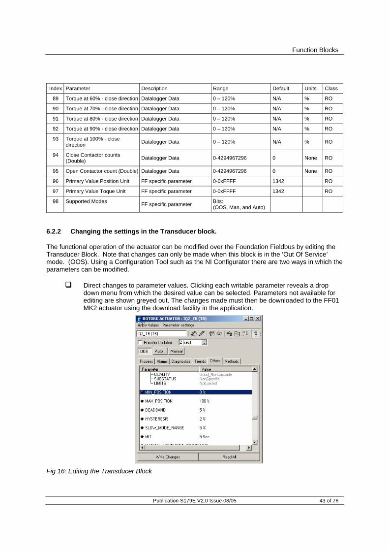
Function Blocks
Publication S179E V2.0 Issue 08/05 43 of 76
Index Parameter Description Range Default Units Class
89 Torque at 60% - close direction Datalogger Data 0 – 120% N/A % RO
90 Torque at 70% - close direction Datalogger Data 0 – 120% N/A % RO
91 Torque at 80% - close direction Datalogger Data 0 – 120% N/A % RO
92 Torque at 90% - close direction Datalogger Data 0 – 120% N/A % RO
93 Torque at 100% - close direction Datalogger Data 0 – 120% N/A % RO
94 Close Contactor counts (Double) Datalogger Data 0-4294967296 0 None RO
95 Open Contactor count (Double) Datalogger Data 0-4294967296 0 None RO
96 Primary Value Position Unit FF specific parameter 0-0xFFFF 1342 RO
97 Primary Value Toque Unit FF specific parameter 0-0xFFFF 1342 RO
98 Supported Modes FF specific parameter Bits: (OOS, Man, and Auto)
6.2.2 Changing the settings in the Transducer block.
The functional operation of the actuator can be modified over the Foundation Fieldbus by editing the Transducer Block. Note that changes can only be made when this block is in the ‘Out Of Service’ mode. (OOS). Using a Configuration Tool such as the NI Configurator there are two ways in which the parameters can be modified.
Direct changes to parameter values. Clicking each writable parameter reveals a drop down menu from which the desired value can be selected. Parameters not available for editing are shown greyed out. The changes made must then be downloaded to the FF01 MK2 actuator using the download facility in the application.
Fig 16: Editing the Transducer Block

Foundation Fieldbus FF01 Mk 2 Installation manual
44 of 76 Publication S179E V2.0 Issue 08/05
Editing the Transducer Block using ‘Methods’. The Method provides a step-by-step
prompted entry dialogue that automatically presents each user-changeable parameter for modification. Non-changeable parameters are not shown. This ‘Method’ of Transducer Block editing simplifies the search for specific values required for editing as shown below and is carried out ‘On Line’ to the actuator.
6.2.3 Editing the Foundation specific parameters 1-23 and 96-98
These parameters include settings that will be specific to the application and the method of control adopted for the network as a whole. Some are related to standard FF functions ands are not described here. Completing the fields listed below will assist on site diagnostics on the installed system by relaying field data to the control room. Index 2 TAG_DESC Enter the tag number allocated to the device. Index 14 ACT_MODEL_NUM Select the type of actuator that the FF01 Mk2 is fitted into
from the list. Index 15 ACT_SN The actuator serial number should be entered in this field.
The serial number appears on the actuator label. Index 20 VALVE_MAN_ID The name of the valve manufacturer may be entered. Index 21 VALVE_MODEL_NUM The valve manufacturer’s model number may be entered. Index 22 VALVE_SN The valve serial number should be entered in this field. Index 23 VALVE_TYPE For example – Gate, Butterfly, may be entered.
Fig 17: Methods editor

Function Blocks
Publication S179E V2.0 Issue 08/05 45 of 76
6.2.4 Editing the actuator setup parameters 50-67
The actuator control performance is determined by a number of settings in this group of parameters. When using direct editing of these parameters close attention should be paid to the function of each. Entering unsuitable values may result in difficulty in controlling the actuator. The parameters are described with their Index numbers.
Index 50 and 51 Limited Range Position Minimum and Maximum These parameters are used to define the positions in the range of valve travel that will be reported as 0 to 100% if the whole travel from the closed position to the open position is not used. In addition the position demand set-point output value will also be modified to follow this limited range.
It is possible to make the position data reported and the position controller relate to a reduced span of actual valve travel. In this mode the position data relates to the reduced portion of the valve stroke. This is sometimes used where the valve is required to have a 0% position (or 100% position) that is not the same as the fully closed position (or fully open position). These parameters define the actual limited range of valve travel that will be used for the position reporting and control by the positioner. Note that the digital open and close commands will still make the valve travel over its full stroke. The special case analogue commands of 0% and 100% that would otherwise cause the actuator to travel to the limit switch or torque off positions are inhibited if values other than 0 and 100 are set in these parameters. The values inserted relate to the maximum total valve travel between closed and open and represent the point in the full stroke which will now be used for the limited stroke 0 and 100 values.
Index 52 and 53 Deadband and Hysteresis When using position control by sending a value to the Actuator Position DV set-point there are a number of parameters used to tune the position controller and reduce the possibility of damage to the actuator. These two parameters are set to prevent hunting around the set-point due to high inertia of the valve. They will require adjustment for each specific application. In addition the Motion Inhibit Timer is used to ensure the actuator does not carry out an excessive number of starts in a given period.
• Deadband The control used for the positioner is proportional only. The FF01 Mk2 will run the actuator to the desired position and then it stops. As the actuator and valve combination have some inertia there is a possibility that the desired position may be overrun and the positioner will then reverse the direction of travel to make the valve adopt the desired position. This overshoot and return may continue for a number of
0% ----------------- Reported Position --------------------- 100% Valve Stroke
CLOSED OPEN
Position Minimum Setting
Position Maximum Setting
Fig 18: Limited Range Position Control and Reporting

Foundation Fieldbus FF01 Mk 2 Installation manual
46 of 76 Publication S179E V2.0 Issue 08/05
cycles and is known as hunting, the valve and actuator combination will hunt around the set-point if the inertia is high. To prevent this from happening there is a Deadband setting whereby once the actuator enters the deadband the motor will be stopped. For example a 5% deadband will cause the motor to be stopped once the actual position is within 5% of the desired position. The inertia will then bring the actual position nearer the desired position.
The deadband is the allowable error around the set-point.
• Hysteresis In addition to the deadband a second setting, Hysteresis, further refines the performance of the position controller. The positioner will run the actuator towards the set-point DV until the actual position is within the deadband minus the Hysteresis setting. This has the effect of instructing the actuator to stop when it is nearer the DV. The actuator will not restart unless it overshoots and runs outside the deadband or a new command places the new desired position outside the deadband.
The Hysteresis is the amount of movement inside the deadband permitted before the motor stops.
Index 54 Slow Mode Range
This parameter is only applicable to IQT actuators. The Slow Mode Range sets the deviation between the set-point and current position in positioning mode inside which the actuator motor will slow to minimum speed. If the set-point (DV) is 50% and the setting for this parameter is 10%, then when the actuator moves within the range 40% to 60% the motor will adopt low speed. The actuator does not use slow mode for digital (Open/Close) commands.
Index 55 MIT (Motion inhibit timer) The Motion Inhibit Timer setting is the period that must elapse between consecutive starts of the actuator motor when in positioning mode. The idle period will prevent the actuator motor from exceeding its rated number of starts per hour.
0% Setpoint DV = 50% 100% Valve Stroke Position MV = 50%
47% 48% 49% 50% 51% 52% 53%
. Hysteresis Hysteresis Hysteresis = 1% Deadband Deadband Deadband = 3%
CLOSED OPEN
Position Minimum Setting
Position Maximum Setting
Fig 19: Deadband and Hysteresis settings

Function Blocks
Publication S179E V2.0 Issue 08/05 47 of 76
In addition, when tuning the valve positioner the setting can be used to allow the plant dynamics to stabilise between valve movements.
Index 56 Manual Movement Travel Manual Movement Travel sets the amount of valve travel not under motor action that is permitted before being considered 'Manual Movement'. The setting must be sufficiently large to cover over run of position control due to valve inertia. If too small the setting will result in Manual Movement alarms each time the valve is positioned, particularly if the deadband is small.
Index 57 Jammed Time Parameter 57 sets the time delay that must elapse without any actuator movement before deciding the Valve Jammed status bit must be set. Valve Jammed is only announced if the actuator is asked to move and fails to respond when it should. The time must be long enough to ensure that the valve is not moving at all.
Index 58 Watchdog Timeout If the watchdog trips to reset the processor the Watchdog Recovery data bit is set. The data bit will automatically reset to '0' after the time period set in this parameter register.
Index 59 to 61 Comms Failure These parameters are used to determine the action taken if there is a failure in the Foundation communications with the actuator and how long the actuator should wait before carrying out the preset action.
• Comms Lost Action (59) The Action on Loss of Comms parameter defines the actuator action that will result after the time set for the Comms Fault Timer (parameter 61) if there is no network communication activity detected by the FF01 Mk2.
• Comms Lost Position (60) The setting in this parameter determines the
position in the range 0 to 100% that the actuator will move to if the Foundation communications stops being received, provided the Action on Loss of Comms (parameter 59) is set to 'Position'. No action will be taken unless the communications stops for a period equal or greater than the setting in the Comms Fault Timer (parameter 61).
• Comms Fault Timer (61) Parameter 61, the Comms Fault Timer setting,
determines the number of seconds that network communication must be absent before the setting for the Fault Mode will be carried out.
Index 62 Auxiliary Mask (Function)
This parameter relates to the IQ and IQT actuators only and allows the auxiliary inputs (open, stop, close, ESD) to be set to control the actuator or simply report their status. In addition it allows the sense of the input (open or closed contact) that is reported as true (1) to be set. Actuator control always requires a true (1) input signal. The status of the inputs is always reported over the network and they can be used to report associated plant inputs instead of controlling the actuator.

Foundation Fieldbus FF01 Mk 2 Installation manual
48 of 76 Publication S179E V2.0 Issue 08/05
The register should be considered in its binary format using the low order byte. The number has the binary form x7x6x5x4, y3y2y1y0, requiring 8 bits. Each bit in the high order nibble, x7x6x5x4, either enables or disables the associated input for control of the actuator. The bits in the low order nibble, y3y2y1y0, determine if the input reports a closed contact as a '1' or an open contact as a '1'. To allow an input to act as a control signal its associated bit in the high order nibble must be set to a '1' in the mask. To allow a closed contact to be reported as a '1' then its associated bit in the low order nibble must be set to '1' in the mask.
Bit Position Value Function 0 Disable ESD input as command 7 X7 1 Enable ESD input as command 0 Disable Stop/Maintain input as command 6 X6 1 Enable Stop/Maintain input as command 0 Disable Close input as command 5 X5 1 Enable Close input as command 0 Disable Open input as command 4 X4 1 Enable Open input as command 0 Report closed contact on ESD input as ‘0’ 3 Y3 1 Report closed contact on ESD input as ‘1’ 0 Report closed contact on Stop/Maintain input as ‘0’ 2 Y2 1 Report closed contact on Stop/Maintain input as ‘1’ 0 Report closed contact on Close input as’0’ 1 Y1 1 Report closed contact on Close input as ‘1’ 0 Report closed contact on Open input as ‘0’ 0 Y0 1 Report closed contact on Open input as ‘1’
The following examples show how the Auxiliary Input Mask settings can be applied. Most Significant Bit Least Significant Bit Bit 7 Bit 6 Bit 5 Bit 4 Bit 3 Bit 2 Bit 1 Bit 0 X7 X6 X5 X4 Y3 Y2 Y1 Y0 Enable
DI-4 ESD
Enable DI-3 Stop
Enable DI-2 Close
Enable DI-1 Open
Invert DI-4
Invert DI-3
Invert DI-2
Invert DI-1
Example 1 0 0 0 0 1 1 1 1 Example 2 1 1 1 1 1 1 1 1 Example 3 0 0 0 0 0 0 0 0
Example 1 The default value of '15' (0000,1111 binary or 0F hex) makes all 4
inputs report closed contacts as true (1) and none of the inputs will operate the actuator.
Example 2 The value 255 (1111,1111 binary or FF hex) makes all 4 inputs report closed contacts as true (1) and all the inputs control the actuator in their predefined way.
Example 3 The value 0 (0000,0000 binary or 00 hex) makes all 4 inputs report open contacts as true (1) and none of the inputs will operate the actuator.

Function Blocks
Publication S179E V2.0 Issue 08/05 49 of 76
Index 63 DI4 ESD/Net Disable
In the IQ/IQT actuator this input determines the mode of operation for the ESD/DI-4 remote input. The input can be used either to disable control of the actuator from the Foundation network, or to act as an ESD/digital input. When this setting is made 'Active' the input will disable network control of the IQ/IQT when the contact input is closed irrespective of the Aux Mask setting.
Index 64 Datalogger Disable The logging of torque and motor contactor starts count can be inhibited if the data logger is turned off.
Index 65 to 67 Partial Stroke The actuator may be instructed to perform a partial stroke that causes the valve to be moved from one end position to an intermediate position and return to the original position. If the action takes longer than the preset time then a timeout indication is given, showing there is a fault.
• Partial Stroke % Travel This parameter sets the position to travel to when a Partial Stroke command is carried out. The partial stroke can be initiated from either the open or the closed position of the valve. The target position can be any value in the range 1-100% where 1 % is near the closed position. Note that the desired value to which the actuator is required to move must be outside the deadband setting.
• Partial Stroke Limit This parameter is used to set two values. The most
significant bit in the register is used to determine the starting position which can be either the open position (1) or closed position (0) for the valve.
• Partial Stroke Timeout The time in which the partial stroke must be successfully
completed.

Foundation Fieldbus FF01 Mk 2 Installation manual
50 of 76 Publication S179E V2.0 Issue 08/05
6.2.5 Editing the control parameters 68-69
Index 68 Control mode Most control schemes will be executed using the multiple bit function provided by a single DO block. DO1 to DO3 have a fixed set of 8 bits each that will suit most applications using discrete control. However, if analogue control alone is being used, or there are some special requirements for the control action, or single bit control is being used, DO4 may need to be used in one of its mode settings. Function Block DO4 can be configured so that the function of the individual control bits is changed to suit a users preferred control scheme. The following options are available. DO (4) Mode Value Type Function of Bit 0 0 0 POS 1 = Position control enable 1 1 ESD 1 = Emergency shut down 2 2 S5 RELAY 1 = Set S5 3 3 PARTIAL STROKE 1 = Partial stroke enable 4 4 AO ONLY None (Analogue only) 5 5 TWO WIRE 0 = Close/1 = Open
Index 69 Discrete block control This parameter is used to set the way the DO blocks will be used. Most systems will be able to support Boolean Fan In functions and consequently the DCS can use a single DO block for all the discrete controls (open/stop/close). This provides for much higher efficiency on the Foundation highway. In this condition the setting for the parameter will be 0 (multiple bit support). For those systems where each DO block performs a single function (e.g. DO(1) = Close) and several blocks are used for the discrete control, it is necessary to set this parameter to 1 (single bit support).
• Multiple Support Systems using the multiple state of a single DO block, with only one DO block selected for use. (Unused DO blocks must be left OOS) Only one DO block may be used if this mode is selected.
• Single Support Systems using only bit 0 from each DO block and using several DO
blocks to obtain discrete control. Only one bit (bit 0) may be used from each DO block in this mode

Function Blocks
Publication S179E V2.0 Issue 08/05 51 of 76
6.3 Analogue Input blocks
The FF01 MK2 includes two Analogue Input (AI) blocks.
AI 1 Valve Current Position (analogue % value) The % ‘Open’ value (position) of the valve. The range is 0-100% and the end values relate to the close (0%) and open (100%) position limit switches.
AI 2 Valve Current Torque Output (analogue % value) IQ only
The instantaneous % torque value throughout the valve stroke. The range is 0-120%.
On installing the card the following settings will apply
The connections to the Transducer block are fixed and in place. The Mode control is standard (Auto, Man, OOS). The Alarms are disabled.
6.4 Discrete Input blocks
There are five Discrete Input Blocks (DI) included on the FF01 MK2 module. These DI’s are preconfigured to read back information from actuator. The description of each reported data bit is included in section 5.
The value reported by each DI block is in the range 0-255. This can be split into 8 discrete binary values, allowing 8 different signals to be reported within each block. The host DCS will need to decode the number into its binary parts using a Boolean Fan In function. In this way the operator can access a large number of discrete signals using a minimum number of function blocks.
Fig 20: Analogue Input Function Block
Fig 21: Discrete Input Function Block
AI
Transducer OutSIMULATE XD_SCALE LOW_CUT OUTPUTPF_TIME
DI
Transducer OutSIMULATE OPTIONALINVERT
OUTPUTPF_TIME

Foundation Fieldbus FF01 Mk 2 Installation manual
52 of 76 Publication S179E V2.0 Issue 08/05
If the host system is not able to support the Boolean function, the first bit in each block represents a different actuator feedback signal and all 5 blocks can be used to transmit 5 bits of discrete data. The use of Boolean functions will maximise the data transmitted with the minimum of network resources. The bit information contained in the first bit of each block is as follows:
DI 1 Single bit (bit 0) status = Actuator at Close Limit. DI 2 Single bit (bit 0) status = Actuator at Open Limit DI 3 Single bit (bit 0) status = Actuator selector in Remote. DI 4 Single bit (bit 0) status = Actuator has a General Alarm. DI 5 Single bit (bit 0) status = Actuator is moving.
The information from each block is shown below.
Block Bit Operation DI1 0
1 2 3 4 5 6 7
Close limit Open limit Actuator moving Actuator closing Actuator opening Selector In remote Selector In local stop Selector In local
DI2 0 1 2 3 4 5 6 7
Open limit Close limit Actuator opening Actuator closing Not in remote General alarm Valve obstructed Valve jammed
DI3 0 1 2 3 4 5 6 7
Selector In remote Selector In local stop Selector In local MIT/Interrupter active Open interlock active Close interlock active Pos. control enabled Slow mode
DI4 0 1 2 3 4 5 6 7
General alarm Thermostat tripped Monitor relay Valve obstructed/jammed Partial stroke alarm Manual movement Battery low Watchdog recovery/fail

Function Blocks
Publication S179E V2.0 Issue 08/05 53 of 76
Block Bit Operation DI5 0
1 2 3 4 5 6 7
Actuator moving DI1- open input DI2- close input DI3- stop maintain DI4- ESD input Open interlock active Close interlock active Partial stroking
On installing the card the following settings will apply
The Mode control is standard (Auto, Man, OOS). 6.5 Analogue Output block
There is one Analogue Output (AO) block in the FF01 MK2 that is designed to allow the valve under control to be positioned to a specific value over its position range of 0-100%.
A0 1 The % open value (position) of the valve. The range is 0-100% and the end values relate to the close (0%) and open (100%) position limit switches. Practical resolution is 1%.
On installing the card the following settings will apply
The output connections to the Transducer block are fixed and in place The Mode control is standard (Auto, Man, LO, OOS). When the actuator local/remote selector is not in the Remote position the block will adopt
LO mode. The IO_OPTS must be set to PV for BKCal_Out
AO
(Transducer)OutOut Convert
XD_SCALE OUTPUTSETPOINT
BKCAL_OUTRCAS_OUT
CAS_IN
RCAS_IN
Channel
READBACK
PVPV ConvertXD_SCALE SIMULATE
Fig 22: Analogue Output Function Block

Foundation Fieldbus FF01 Mk 2 Installation manual
54 of 76 Publication S179E V2.0 Issue 08/05
For the correct operation of the AO block the setting IO_OPTS = PVforBKCal_Out should be performed in the function block during the configuration of the Foundation Fieldbus. This setting is found within the AO function block dialogue box in the options folder as shown in Fig 23. Setting it to this value ensures that the BKCal_Out value follows the actual valve position if the actuator is moved manually, by the local controls or by other electrical means.
The AO block acts as a positioner for the valve and actuator. The positioning action is initiated by setting the DO function to Position Enable through the DO blocks, or by setting the Control Mode (Transducer block parameter 68) to AO only. Each time the positioner is enabled the actuator will move to the value set in the AO block provided the actuator is local/remote selector is in the remote position.
6.6 Discrete Output blocks
Discrete (open/stop/close) control of the actuator, or mixed discrete and analogue position control is possible provided the FF01 Mk2 module is set up correctly in the Transducer block and the correct settings are applied. There are 4 Discrete Output (DO) blocks in the FF01 Mk2 that allow the actuator to be moved. In addition, when the optional relay output board is fitted, the four relays may be controlled.
Note: The block option for IO_OPTS must be set to PVforBKCal_Out for correct operation of a control or positioning function.
Fig 23: Setting IO_OPTS to PVforBKCal_Out
Note: The AO block will only control the actuator position when the DO setting is for Position Enable or the appropriate Transducer block parameter is set for AO only mode.

Function Blocks
Publication S179E V2.0 Issue 08/05 55 of 76
As with the DI blocks, the DO blocks make use of all 8 bits within each block. The actuator will respond to values between 0 and 255 sent via one DO block when multiple support is selected, or to the value of the first bit (0/1) when single bit and one or more DO blocks are used. Single or multiple bit discrete use is selected using parameter 69 in the transducer block. When multiple bit support is selected only one of the DO blocks may be used for discrete control. If control using DO(4) is adopted it is necessary to set the mode for this block using parameter 68 in the transducer block.
On installing the card the following settings will apply
The output connections to the Transducer block are fixed and in place The Mode control is standard (Auto, Man, LO, OOS). When the actuator local/remote selector is not in the Remote position the block will adopt
LO mode. The IO_OPTS should be set to PV_D for BKCal_Out_D
Where multiple support is selected, only one DO should be set to Auto. All other DO blocks must be set to Man or OOS. 6.6.1 Multiple block – single bit control
DO 1 Bit 0 = ‘Close’. DO 2 Bit 0 = ‘Open’. DO 3 Bit 0 = ‘Stop’ DO 4 Bit 0 = selected by mode
Mode Bit 0 Function 0 Position Enable 1 ESD 2 Set/reset relay DO-1 3 Partial Stroke 4 Not Applicable (AO only control) 5 0= close, 1 = open
Fig 24: Discrete Output Function Block
DO
(Transducer)Out_DOPTIONAL
INVERT OUTPUTSETPOINT
BKCAL_OUT_DRCAS_OUT_D
CAS_IN_D
RCAS_IN_D
Channel
READBACK_D
PV_D SIMULATEOPTIONAL INVERT

Foundation Fieldbus FF01 Mk 2 Installation manual
56 of 76 Publication S179E V2.0 Issue 08/05
6.6.2 Single block – multiple bit control.
The table below identifies the function of each bit in the available DO block when multiple bit control is selected. PV_D comes from READBACK from the appropriate ‘status inputs’. The bold text in the read-back column indicates bits that only echo the command operation. Block Bit Operation Read-back DO1 0
1 2 3 4 5 6 7
Close Open Stop ESD Position enable DO-1 relay set DO-2 relay set DO-3 relay set
Close limit Open limit Actuator not moving ESD Position control enabled DO-1 relay set DO-2 relay set DO-3 relay set
DO2 0 1 2 3 4 5 6 7
Open Close Stop ESD Partial stroke DO-1 relay set DO-2 relay set DO-3 relay set
Open limit Close limit Actuator not moving ESD Partial stroking DO-1 relay set DO-2 relay set DO-3 relay set
DO3 0 1 2 3 4 5 6 7
Stop Close Open Pos enable DO-1 relay set DO-2 relay set DO-3 relay set DO-4 relay set
Actuator not moving Close limit Open limit Position control enabled DO-1 relay set DO-2 relay set DO-3 relay set DO-4 relay set
DO4 Mode 0 0 1 2 3 4 5 6 7
Position enable Close Open ESD DO-1 relay set DO-2 relay set DO-3 relay set DO-4 relay set
Position control enabled Close limit Open limit ESD DO-1 relay set DO-2 relay set DO-3 relay set DO-4 relay set

Function Blocks
Publication S179E V2.0 Issue 08/05 57 of 76
Block Bit Operation Read-back DO4 Mode 1:
0 1 2 3 4 5 6 7
ESD Close Open Position enable DO-1 relay set DO-2 relay set DO-3 relay set DO-4 relay set
ESD Close limit Open limit Position control enabled DO-1 relay set DO-2 relay set DO-3 relay set DO-4 relay set
DO4 Mode 2: 0 1 2 3 4 5 6 7
DO-1 relay set Close Open ESD Position enable DO-2 relay set DO-3 relay set DO-4 relay set
DO-1 relay set Close limit Open limit ESD Position control enabled DO-2 relay set DO-3 relay set DO-4 relay set
DO4 Mode 3: 0 1 2 3 4 5 6 7
Mode 3: Partial stroke Close Open ESD DO-1 relay set DO-2 relay set DO-3 relay set DO-4 relay set
Mode 3: Partial stroking Close Open ESD DO-1 relay set DO-2 relay set DO-3 relay set DO-4 relay set
DO4 Mode 4: N/A (used for AO only control)
N/A
DO4 Mode 5: Value. 0 – Close 1 – Open Any other value sends Open command.
Value. 0 – Close 1 – Open
Note: Ensure that parameters 68 and 69 in the Transducer block are set for the type of control and DO4 mode required.

Foundation Fieldbus FF01 Mk 2 Installation manual
58 of 76 Publication S179E V2.0 Issue 08/05
6.7 PID Control block
The actuator includes a standard three-term PID controller block for use in a control loop. The inputs and outputs of this block are not directly linked to the actuator Transducer block. This allows the PID controller to be used for controlling devices other than the actuator. With a PID function as long as an error exists between the set point (desired value) and the measured value feedback (process variable) the controller will change the output in a direction to reduce the error. The way in which the output changes is influenced by the actual error value, the time it is present and the rate of change it undergoes. The PID settings applied Integrate the error with respect to time (RESET value), apply a proportional gain on the error (GAIN) and differentiate the rate of change in the error (RATE); all these actions are combined to produce the OUTPUT.
PID A stand-alone 3-term controller within the actuator.
The PID block must be connected and set up before it can be used. It is the only block in the FF01 MK2 module that is not pre-connected to any input or output of the actuator transducer block and may be freely connected into a control loop. The scheduler is used to allocate a time slot for the control algorithm to execute. Further information on the PID function block can be found in Appendix C of this manual.
PID
OUT
BYPASS
OUTPUT
SETPOINT
BKCAL_OUTRCAS_OUT
CAS_IN
RCAS_IN
SP
FF_SCALEFF_GAIN
TRK_SCALETRK_IN_D
TRK_VAL
GAINRESET
BAL_TIMERATE
PV_TIMEIN PV
FF_VALBKCAL_IN
ROUT_IN ROUT_OUT
Fig 25: PID Function block

Link active Scheduler
Publication S179E V2.0 Issue 08/05 59 of 76
7 LINK ACTIVE SCHEDULER
Foundation devices may be either Basic or Link Master devices. Basic units do not have the ability to hold the timing schedule for scanning the nodes and cannot act as system controllers. Every network requires at least one Link Master to control the network communications. A Link Master that is in control of the communications is known as a Link Active Scheduler. All FF01 MK2 modules are capable of acting as Link Masters and assuming network control by switching automatically to become the Link Active Scheduler. This option must be checked during commissioning and may be configured as enabled or disabled. As many as are required can be switched to this mode since only one will become the active device at any one time.
In order to change the FF01 MK2 from a Basic unit to a Link Master a suitable configuration tool or dialogue tool must be used. The setting is contained in the Management Information Base (MIB) and the data base must first be opened using the dialogue tool. The parameter to be altered resides in the MIB type of VFD. The class is called BOOT_OPERAT_FUNCTIONAL_CLASS This class can have two values, 01 = Basic Unit 02 = Link Master Edit the value and download the setting to obtain the desired function. The type of functionality available can also be read in the parameter DLME_BASIC_CHARACTERISTICS / DL_OPERAT_FUNCTIONAL_DEVICE_CLASS A value of 1 indicates a basic unit whilst a 2 indicates a Link Master. Once the type has been selected the configuration tool can be used to download the system configuration. The schedule will reside in all the Link Masters and be executed by the one that is active, the Link Active Scheduler. Should the LAS fail then any of the remaining Link Master units is able to take the role of LAS.
Fig 26: Link Active Scheduler – one per network
FieldbusPowerSupply
+-
T
T
A 1
A 2
A 3 A 5
A 4 A 6
LAS

Foundation Fieldbus FF01 Mk 2 Installation manual
60 of 76 Publication S179E V2.0 Issue 08/05
When initially setting up a system using FF01 Mk2 modules that are in Link Master mode it is essential to connect the actuators to the bus after the configuration utility is started or after the DCS gateway port is connected. If an actuator in Link Master mode is connected first it will automatically become the LAS (Active Scheduler device) and the configuration tool will be unable to gain full control of the network.
7.1 Creating a schedule
In order to use any Function Block with the exception of the Resource Block, the required blocks must be placed in a ‘Function Block Application’ using a suitable configuration tool. This ensures the blocks are processed by the LAS in the correct way, allowing them to publish data when required. Note that blocks do not have to be interconnected at this stage. Once a control strategy has been worked out the individual function blocks for all network devices distributed across the network can be interconnected using the DCS or a configuration tool. The configuration process also includes formatting the schedule for the execution of the function blocks.
Fig 27: Management Information Base (MIB) showing BOOT_OPERAT_FUNCTIONAL_CLASS
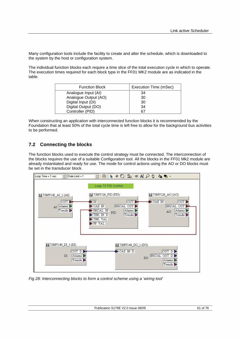
Link active Scheduler
Publication S179E V2.0 Issue 08/05 61 of 76
Many configuration tools include the facility to create and alter the schedule, which is downloaded to the system by the host or configuration system. The individual function blocks each require a time slice of the total execution cycle in which to operate. The execution times required for each block type in the FF01 MK2 module are as indicated in the table.
Function Block Execution Time (mSec) Analogue Input (AI) 34 Analogue Output (AO) 30 Digital Input (DI) 30 Digital Output (DO) 34 Controller (PID) 67
When constructing an application with interconnected function blocks it is recommended by the Foundation that at least 50% of the total cycle time is left free to allow for the background bus activities to be performed. 7.2 Connecting the blocks
The function blocks used to execute the control strategy must be connected. The interconnection of the blocks requires the use of a suitable Configuration tool. All the blocks in the FF01 Mk2 module are already instantiated and ready for use. The mode for control actions using the AO or DO blocks must be set in the transducer block.
Fig 28: Interconnecting blocks to form a control scheme using a ‘wiring tool’

Foundation Fieldbus FF01 Mk 2 Installation manual
62 of 76 Publication S179E V2.0 Issue 08/05
(This page intentionally left blank.)

Setting up the FF01 module
Publication S179E V2.0 Issue 08/05 63 of 76
8. SETTING UP THE FF01 MK2 MODULE
Both the actuator and the FF01 Mk2 module must be set up correctly to achieve the desired control. When the FF01 Mk2 module is in an IQ or IQT actuator some of the settings can be made using the IR setting tool, but in all cases the action of the module may be set using either direct alterations to the parameters in the Transducer block or by the Methods settings, also in the Transducer block. Q range actuators do not include IR setting capabilities and must be set using a configuration tool. 8.1 Setting up an IQ or IQT with the Setting Tool
The IQ and IQT actuator includes an infra-red communication port for setting the actuator performance, limit switches and so on. This communication link can be used to set some, but not all, of the FF01 Mk2 Transducer block parameters. The parameters should still be checked with a configuration utility to ensure optimum actuator and network compatibility. The diagram illustrates the access route through the actuator menu screens to reach the settings that affect the FF01 Mk2.
[Od] function must be set to [OP]; if it is not then the card will not be able to control the actuator.
[OF] Folomatic must be set to ON [OP] Bus Option must be set to ON
The Transducer block parameters that may be set by using the Setting Tool and the infra red link are listed below. The available range for the deadband setting when using the setting tool is less than the range found using the configuration tools.
Parameter
No. Menu Code Description Range Default
Value 50 FL Limited Range Position Minimum 0 – 100% 0% 51 FH Limited Range Position Maximum 0 – 100% 100% 52 Fd Deadband 0.0 – 9.9% 5.0% 55 Ft Motion Inhibit Time 0 – 255 sec 5 sec
59 FA Action on Loss of Comms Nothing (No Action), Stop, Close, Open, Position Nothing
60 FF Comms Lost Position 0.0 – 100.0% 0.0% 62 PF Aux Input Mask 0 – 255 (00 – FF hex) 15 (0F)
Note: When altered, the new value will only take effect after the actuator power has been cycled once.
The table below shows the Setting Map available when using the IR tools.
Note: Parameters may only be altered by the IR link if the actuator control knob is set to the Local or Local Stop position.

Foundation Fieldbus FF01 Mk 2 Installation manual
64 of 76 Publication S179E V2.0 Issue 08/05
8.2 Methods
The Methods tab on the Transducer block allows access to a sequence of questions that set up all the actuator control parameters as they are answered. When the Methods editor is used ALL the questions must be answered, even if there is no change required to the default values. The Methods editor ensures that all the necessary parameters are set before the actuator is used for control of the plant. The most critical decision that has to be made is for Discrete control, where either multistate or single bit support can be chosen. Multistate control allows for only one DO block to be set to Auto.
Position Display
Position Display + Torque
Password
CR R1 R2 R3 R4 A1 A2 A3 A4 A5 A6 A7 A8 A9 ESD
action ESD
contact type
ESD t/stat
bypass
ESD override
interlocks
ESD override
local stop
Maintained local
control
2-wire control
External interlocks
Conditional control
OE OI OF Od OP OJ Or OS Extra
indication contacts
CPT Folomatic remote control
(must be ON)
Remote control source
(must be set to OP)
Bus system option
(must be ON)
Interrupter timer
Setting tool local control
Power loss
inhibit
PA PB PF PP Address
Range 01-FF
Baud rate
Aux I/P mask
Parity setting
FI Fr FL FH Fd Ft FA FF Set point
signal type
Set point signal range
Low set point 0% position
limit
High set point 100%
pos limit
Position control
deadband
MIT Action on loss
of signal
Action on loss
of signal position
R5 Etc.
Fig 29: Setting tool menu structure and FF01 Mk2 settable parameters. For more information see Rotork publication E170E2.

Setting up the FF01 module
Publication S179E V2.0 Issue 08/05 65 of 76
The recommended way to set up the control and reporting function of the FF01 Mk2 module is to use the Methods editor. 8.3 Control output function block settings
Depending on the actual function blocks used in the application there will be different requirements for some of the Transducer block settings. All of the Transducer block parameters are described in section 6.2 Transducer Block. This section shows the most popular settings that can be adopted for control of the actuator. The action of including the function blocks in the application declares to the LAS those instances to be included in the exchange of information. All the available function blocks need not be added to the application, but those not included will not provide their information to the fieldbus.
The Transducer Block must be in Auto Mode for control to take place.
When multi-state is selected, the desired Digital Output control block also requires to be placed in Auto Mode.
All other blocks should be placed in either Man Mode if used in the monitoring
scheme or OOS if not required. In order for a configuration tool such as those supplied by SMAR, NI and Yokogawa to parameterise the Actuator Fieldbus Card, the correct Device Definition files need to be loaded in to the configuration environment. These files are freely available for download from www.rotork.co.uk.
Fig 30: Setting the module using Methods from the Transducer block

Foundation Fieldbus FF01 Mk 2 Installation manual
66 of 76 Publication S179E V2.0 Issue 08/05
The Foundation Fieldbus control of the actuator can be:
Position using a position demand set-point only Discrete using Open/Stop/Close commands Mixed Discrete/Position using a position demand set-point and ‘Run’ signal
8.3.1 Analogue Only control
Uses AO block only – no discrete control permitted. Transducer Block Settings
Index 52 – Deadband Set between 0-25.5% (typically 2%) Index 53 – Hysteresis Set between 0-100% (typically 5%) Index 55 – Motion Inhibit Timer Set between 0-255 seconds (typically 3 sec) Index 68 – Control Mode Set to 0
Analogue Output Block Settings IO_OPTS Must be set to PV for BKCal_Out
8.3.2 Discrete Only control
Uses one or more DO block only – no position (%) control permitted. The support available from the DCS will determine how many blocks are required. Where Boolean Fan In functions are available Multiple support can be chosen and a single block used.
Multiple Support Systems using the multiple state of a single DO block, with only one DO block selected for use. (Unused DO blocks must be left OOS) Only one DO block may be used if this mode is selected. The actual block selected will depend on the actual discrete control functions required. In most cases DO(1) or DO(2) will be the most useful.
Transducer Block Settings
Index 68 – D0(4) Mode Set between 1 and 5 if this block is used Index 69 – Discrete Block Control Set Multiple to use Boolean Fan In and one DO block.
Single Support Systems using only bit 0 from each DO block and using several DO blocks to obtain discrete control. Only one bit (bit 0) may be used from each DO block in this mode
Transducer Block Settings
Index 68 – D0(4) Mode Set between 1 and 5 if this block is used
Index 69 – Discrete Block Control Set Single to use only values of 0/1 in several DO blocks

Setting up the FF01 module
Publication S179E V2.0 Issue 08/05 67 of 76
8.3.3 Mixed Analogue and Discrete control
Uses the AO block and one or more DO block.
Multiple Support Systems using the multiple state of a single DO block, with only one DO block selected for use. (Unused DO blocks must be left OOS) Only one DO block may be used if this mode is selected. The actual block selected will depend on the actual discrete control functions required. In most cases DO(1) will be the most useful.
Transducer Block Settings
Index 52 – Deadband Set between 0-25.5% (typically 2%) Index 53 – Hysteresis Set between 0-100% (typically 5%) Index 55 – Motion Inhibit Timer Set between 0-255 seconds (typically 3 sec) Index 68 – D0(4) Mode Set between 1 and 5 if this block is used Index 69 – Discrete Block Control Set Multiple to use Boolean Fan In and one DO block.
Analogue Output Block Settings IO_OPTS Must be set to PV for BKCal_Out
Single Support Systems using only bit 0 from each DO block and using several DO
blocks to obtain discrete control. Only one bit (bit 0) may be used from each DO block in this mode
Transducer Block Settings
Index 52 – Deadband Set between 0-25.5% (typically 2%) Index 53 – Hysteresis Set between 0-100% (typically 5%) Index 55 – Motion Inhibit Timer Set between 0-255 seconds (typically 3 sec) Index 68 – D0(4) Mode Set to 0 and use DO(4) to enable position control
Index 69 – Discrete Block Control Set Single to use only values of 0/1 in several DO blocks
Analogue Output Block Settings
IO_OPTS Must be set to PV for BKCal_Out 8.3.4 Hard wired inputs - Aux Input Function
If hard-wired Auxiliary inputs are required either to control the actuator, or simply as digital status feedback signals, the Auxiliary function Mask (Index 62) will need to be set in the Transducer Block to ensure the sense and function of the inputs provide the desired control action. 8.4 Status feedback function block settings
The current status of actuator position, active control functions and fieldbus availability are reported in several parameters of the transducer block and through the Discrete Input and Analogue Input blocks. The only settings that need be considered are those for limited range positioning.

Foundation Fieldbus FF01 Mk 2 Installation manual
68 of 76 Publication S179E V2.0 Issue 08/05
8.4.1 Analogue position and torque data
Before the actuator can accurately report the position of the valve the actuator Open and Closed limits must be set and the actuator moved between the fully open (100%) and fully closed (0%) positions. If the Fieldbus reported positions are required to be a proportion of the available stroke, this reduced band can be set in the transducer block using parameters 50 and 51. Transducer Block Settings
Index 50 – Min Position Set between 0-100% (usually 0%) Index 51 – Max Position Set between 0-100% (usually 100%)
8.4.2 Discrete Input data
The Discrete Input blocks provide actuator status information. This can be read either as a single bit read from all five DI function blocks or multiple bit reads from one or more blocks if required. The following example shows a monitoring configuration where only a single bit read is available.
DI 1 bit 0 = Actuator at Close Limit. DI 2 bit 0 = Actuator at Open Limit DI 3 bit 0 = Actuator selector in Remote. DI 4 bit 0 = Actuator has a General Alarm. DI 5 bit 0 = Actuator is moving.
The Host DCS will monitor the OUT_VALUE of each of the DI blocks. Each block will be examined for the change in value from 0 to 1 to detect the present status. The following example shows a monitoring configuration using multiple bit reads from DI 1.
DI 1 bit 0 = Actuator at Close Limit. DI 1 bit 1 = Actuator at Open Limit DI 1 bit 2 = Actuator is Moving. DI 1 bit 3 = Actuator is Closing. DI 1 bit 4 = Actuator is opening. DI 1 bit 5 = Actuator selector in Remote. DI 1 bit 6 = Actuator in Local Stop DI 1 bit 7 = Actuator in Local.
When using multiple bit reads from a single byte the DI will show a numeric value based on the combined binary values of each bit at logic 1. For example the number 52 in the OUT_D VALUE parameter of DI 1 would denote the actuator has Remote selected and is Moving open. 8.4 Downloading the settings to the Actuator
Once the configuration of the function blocks has been completed, this must be downloaded to the actuator. Where a number of Actuators are required to have the same settings, the configuration file can be saved and copied to several differently tagged devices in turn.

Setting up the FF01 module
Publication S179E V2.0 Issue 08/05 69 of 76
8.5 Default settings
Transducer Block Parameter Index No. Description Range Default Setting
50 Limited Range Position Minimum 0-100% 0% 51 Limited Range Position Maximum 0-100% 100% 52 Deadband 0.0-25.5% 5.0% 53 Hysteresis 0.0-25.5% 2.0% 54 Slow Mode Range 0-100% 5% 55 Motion Inhibit Time 0-255s 3 sec 56 Manual Movement Travel 0-100% 10% 57 Valve Jammed Time 0-255s 5 sec 58 Watchdog Timeout 0-255s 10 sec
59 Action on Loss of Comms
Value: 0 – No Action 1 – Open 3 – Close 5 – Stop 7 – Position Any other value = off
0 (No action)
60 Comms Lost Position 0-100% 0% 61 Comms Fault Timer 0-255s 10 sec 62 Aux Input Mask 0x00-0xFF 0F
63 ESD DI-4/Net Disable 0- ESD function 1- Network disable 0
64 Data Logger disable 0- Datalogger enabled 1- Data logger disabled 0
65 Part stroke % travel position 0-100% 95%
66 Part stroke limit 0 – Close limit 1 – Open limit 1
67 Part stroke timeout 0-7200 seconds 300 sec
68 Control Mode [DO(4) function]
Value: 0 – Positioning mode 1 – ESD 2 – S5 relay operate 3 – Partial stroke 4 – AO only 5 – Two wire control
0
69 Discrete Block control Bit: 0 – Multiple support 1 – Single support
0

Foundation Fieldbus FF01 Mk 2 Installation manual
70 of 76 Publication S179E V2.0 Issue 08/05
This page intentionally left blank.

Publication S179E V2.0 Issue 08/05 71 of 76
9 THE FF01 MK2 FIRMWARE AND DD FILES
9.1 Firmware
The firmware embedded in the processors on the network interface card and also on the Interface card is contained in reprogrammable memory devices. These are either EPROM or Flash upgradeable devices. These require special equipment for their contents to be altered. Should the module require to be reprogrammed it is necessary to return the whole module to Rotork. The two module parts must not be separated and any revision to the embedded firmware will require both parts to be returned.
9.2 Device Description Files
The FF01 Mk2 module operates in conjunction with Foundation Fieldbus compliant device description files. These have been tested as part of the certification process to ensure compatibility with the Foundation standards. From time to time there may be revisions to these files to allow enhancements to the module to become effective. Where these enhancements are related to the actuator itself there may not be a full retest of the module by the Foundation. The Rotork web site is regularly maintained and always contains the latest version of the DD files for the module. These may be newer than those posted by the Foundation on their web site. We recommend downloading the latest version from the Rotork web site at www.rotork.com. When downloading these files please take great care to ensure the files are compatible with the version of Fieldbus card with which they will be used. The files applicable to the earlier FF-01 Mk1 module are not compatible with the FF01 Mk2 module. In some cases the application may require downloading additional special files from the DCS vendor’s web site. Please check with the DCS web site for these files.
File File Name ITK Version Capabilities File 010103.cff 4.6 Symbol File 0101.sym 4.6 Device Description 0101.ffo 4.6

Foundation Fieldbus FF01 Mk 2 Installation manual
72 of 76 Publication S179E V2.0 Issue 08/05
APPENDIX A – HANDLING FAULT CONDITIONS.
Foundation Fieldbus blocks have a large number of parameters which influence the way in which the actuator responds to commands from the Fieldbus. In the event that communications are lost to the actuator, a number of these parameters are available to allow a predictable and deterministic reaction. The example below shows how an action may be configured to determine how a Digital Output Block will react on the loss of the cascade input to the block.
Settings dialogue as seen in National Instruments NI-FBUS Configurator. This type of configuration is possible for all of the DO and AO blocks in the actuator.
Option tab
Input/Output options selected to report Fault state.
Delay before action takes place.
This value is written to the output of the block after the time delay. In this case ‘2’ is written to the output of the DO block.
This function block has been renamed with a Tag reference.

Publication S179E V2.0 Issue 08/05 73 of 76
APPENDIX B – FUNCTION BLOCK MODE – LO
The status of each of the Function blocks can be read by the Host system. Each block has a minimum of three states which are OOS – Out Of Service AUTO – Automatic CAS - Cascade MAN – Manual IMAN - Initialise Man mode (Not a permanent condition) Blocks may have one other state which is LO - Local. The blocks must be part of the downloaded configured Function block application. This mode is entered when the actuator selector switch is either in the STOP or LOCAL position. This mode is also entered when the network disable feature is chosen for DI4. See section 5.1. The blocks can also adopt this mode if an illegal data type is presented to an input. In the example for the AO block shown, values may still be written to the Output of the block. If the actuator is returned to the Remote Operation state, if the output value is outside the dead-band of the actuator, the valve will be moved to the new position.
LO is displayed as shown in the NI Configuration tool. This status can be read by a HOST application.

Foundation Fieldbus FF01 Mk 2 Installation manual
74 of 76 Publication S179E V2.0 Issue 08/05
APPENDIX C – PID APPLICATION.
The diagram above illustrates the settings available in the PID such as PV_SCALE (Process variable scaling factor) and the interdependencies that occur with, in this case PV and SP. By utilizing the block diagram it should be possible to ‘scale’ the PID to achieve the required control regime.
In this example, a flow transmitter FT provides a measurement (PV) which is required to position an actuator M (OUTPUT) to maintain the required process flow with respect to a set point (SP).
Diagram of the PID Function Block showing the relationship of the
various parameters.

Publication S179E V2.0 Issue 08/05 75 of 76
APPENDIX C – PID APPLICATION. Continued. The function block application which might be configured for this application is shown below. In this case the National instruments configurator has been used.
This dialogue box is used to adjust the scaling of the parameters supplied to or derived through the processing of the control loop. In the block diagram of the PID function block these values can be seen and their relationship to the control algorithm. The Choice of the correct scaling and engineering units is important in the correct operation of the block.

Foundation Fieldbus FF01 Mk 2 Installation manual
76 of 76 Publication S179E V2.0 Issue 08/05
APPENDIX C – PID APPLICATION Continued.
Familiar tuning constants can be seen in this dialogue block together with others specific to this implementation of a PID block. For full information on the operation, configuration and tuning of PID loops all the relevant loop component manufacturers information should be referred to.
UK Head Office Rotork Controls Ltd Bath England BA1 3JQ Tel: +44 (0) 1225 733 200 Fax: +44 (0) 1225 333 467 e-mail: [email protected]
USA Head Office Rotork Controls Inc 675 Mike Crossing Blvd Rochester New York 14624 USA Tel: +1 716 328 1550 Fax: +1 716 328 5848 e-mail: [email protected]
htpp://www.rotork.com