forwards supplemental response to ser open item 3.10.1(3
TRANSCRIPT
RFGUI.ATORY * 'ORMATION DISTRIBUTION SY M (RIDS)
ACCESSION NBR; 83061k064l8 OOC ~ DATE: 83/06/09 NOTARIZED: NO DOCKETFACILg50.587 8usquehanna Steam Electric Stationr. Unit li Pennsylva 05000387
.50 388 Susquehanna. Steam Electric Station< Uni,t 2< Pennsylva 05000388AUTH'AMK AUTHOR Al FLLIATION
CURTIS r N ~ >l ~ Pennsylvania Power 8 Light Co+,AECIP,NAME RECIPIENT AFFILIATION
SGHNENCERrA ~ Licenssng* Branch'
SUBJECT: For wards supplemental response to SER Open Item 3 ~ 10 ~ 1(3) ~
Fat>gue cycling effects on NSSS equipment due to safetyrelief. loads (License Condition 23(a)) di.scussed,
DISTRIBUTION CODE'001S -GOPIES RECEIVED:LTR, ENCL .Q SIZE;,TITLE: Licensing'Submittal: .PSAR/FEAR Amdts 8 Related Correspondence
NOTES: 1cyNMSS/FCAF/PM'cyNMSS/FCAF/PM'500038705000388
RECIPIENTIO CODE/NAME
NRA/DL/AOLHRA f.82 LA
INTERNAL: ELO/HOSPIE/DEPKR/EPB 36IE/DEQA/QAB ?1NRR/DE/CEB 1|NRR/DE/EQB 13t4RA/OE/MKB 18NRR/DE/SAB 24NRA/OE/SGEB. 35NRR/DHFS/LQB 32hlRA/OL/SSPBNRA/DSI/ASBNRR/OSI'/CSB 09LIRA/DSI/METB 12NR - 6 22
G F I l E 04/MIB
EXTERNALS ACRS 41DMB/DSS (AMDTS)I PGR 03NSIC 05
NOTES:
~COPIESLTTR ENCL
10"
0
1 0
1
2 2i
1
1
i 1
1 0
ii 1
1
1
0
1
2 21
1 1
RECIPIENTID CODE/NAME
NRR L82 BGPERCHrR ~ 01
IE F II.EIE/OEPER/IRB 35NRR/DE/AEABNRR/DE/EHEBNRR/DE/GB 28NRR/DE/MTEB 17NRR/DE/SGEB 25NRR/DHFS/HFEB40NRR/DHF8/PSRBNRR/DS I/AEB 26NRR/DSI/CPB i 0
NRR/DSI/ICSB i6NRR/DSI/PSB i&NRR/DS I/RSB 23RGN1
BNL(AMOTS ONLY)FEMA~REP OI'Ii 39NRC PDR 02NTIS
COPIESLTTR ENCL
1 01 1
1 1
1 1
01 1
2 21
1 1
1
1
TOTaL NUMBER OF COPIES REQUIRED: LTTR 56 ENCL 49

\ g)s >v
4'I,~r ~
Pennsylvania Power 8 Light CompanyTwo North Ninth Street ~ Allentown, PA 18101 ~ 215 l 770.5151
Norman W. CurtisVice President-Engineering 8 Construction-Nuclear21 5/770-7501
JUN 09 1983
Director of Nuclear Reactor RegulationAttention: Mr. A. Schwencer, ChiefLicensing Branch No. 2
Division of LicensingU.S. Nuclear Regulatory CommissionWashington, D.C. 20555
SUSQUEHANNA STEAM ELECTRIC STATIONNSSS EQUIPMENT FATIGUE EVALUATION-SUPPLEMENTARY DATALICENSE CONDITION (23)(a) AND SER ITEM 3.10.1(3)ER 100450 FILE 148-01PLA-1698
Reference: 1) PLA-1222, dated 7/29/82 from N. W. Curtis to A. Schwencer
Dear Mr. Schwencer:
This letter and its attachments contain the data requested by the NRC tosupplement our response (Reference,l) to your concerns regarding the fatiguecycling effects on NSSS equipment due to SRV loads (License Condition 23(a)and SER Item 3.10.1(3)) .
1.0 Number of SRV Events for BWR-4 Reactors
Derivation of the HPCI turbine fatigue test requirements indicatedthat 900 SRV actuations were appropriate for equipment fatigue designin BWR-4 plants. This value is based on empirical data from theoperation of Browns Ferry and Peach Bottom.
Based on observed response time histories of components due to SRV
loads, two (2) significant peak load cycles on equipment outsidecontainment and four (4) significant peak load cycles on equipmentinside containment can be expected for one (1) SRV actuation.Consequently, the number of peak load cycles due to SRV actuationspostulated for the 40 years of plant operation is 3600 for equipmentinside containment and 1800 for equipment outside containment.Observing that the significant load cycles from an SRV dischargeoccur within the first half second of the event, the fatigue agingrequired time in a response spectrum test is approximately 450 seconds(7.5 minutes) .
"830bi40b48 830b09PDR ADOCt|'5000387E , PDR
t
goo i
t (
sg, rl,
JUN 09 1983Page 2 SSES PLA-1698
ER 100450 File 148-01Mr. A. Schwencer
2.0 E ui ment Fati ue Anal sis and Testin — Su lementa Information
The following information is provided as a quantitative backup todemonstrate that the SRV fatigue aging requirement of Paragraph 1.0 ismet for'he equipment previously identified in Reference 1.
2.1 ~anal sls:
Fatigue analyses were performed for the five components listed insection 1 of Reference l. Based on an environment with 1800 significantstress cycles (as explained above for equipment outside containment),the maximum usage factor (or cumulative damage factor) was 0.33 whichoccurred on the RCIC pump holddown bolts (5500 cycles allowed for thecalculated fatigue stress) . The calculations are contained withinAttachment l.
2.2 Test:
Supportive data is given below for equipment whose fatigue lifeadequacy was demonstrated using methods of extended duration testing.
2.2.1 MSIV-LCS Blower (E32-C001/C002)
Extended duration testing was performed on the blower. The total testtime was 40 minutes and was achieved as follows:
a) 4 Upset Condition Tests (OBE + SRV) for 5 minutes each at 2g'sinput.
b) 4 Faulted Condition Tests (SSE + SRV + LOCA) for 5 minutes eachat 3g's input.
These g-levels are far in excess of the O.llg ZPA of the required SRV
spectra. See the SQRT form in Attachment 2. For the sine sweep testmethod which was performed in the range of 3.8 to 33 hertz, severalthousand cycles minimum per each 5 minute test was imposed on the testspecimen such that the cumulative number of cycles greatly exceededthe required 3,600 cycles from Section 1.0. Neither structural noroperability failure occurred during this testing.
2.2.2 Electrical Cabinets
Additional extended duration testing of the cabinets with mounteddevices was performed to demonstrate fatigue life adequacy of thisequipment. Test programs and results are described below.
2.2.2.1 4.16KV Switchgear
The extended duration test is verified on- pages 2 and 3 of the SQRT
form in Attachment. 3. A biaxial sine sweep test covering the ampli-fied portions of the SRV spectrum (4 to 70 Hz) was performed inboth the side-to-side/vertical and front-to-back/vertical orienta-tions in the single cell configuration and in the front-to-back/

@i
1I ~
V
JUN 09 1983Page 3 SSES PLA-1698
ER 100450 File 148-01Mr. A. Schwencer
vertical orientation only for the multiple cell configuration. TheSRV fatigue tests were performed by sweeping up and down at a sweeprate of one octave per minute for 30 minutes. The input accelerationlevel was approximately 0.08 g. This sinusoidal input level wouldproduce a spectral acceleration level of approximately 2 g at 2%
damping, which is well above the SRV + LOCA levels of approximately0.9 g.
2.2.2.2 125 VDC Power Distribution Panel
Upon completion of the first combined load qualification test, SRV
fatigue tests were performed using multi-frequency biaxial motion(XY and ZY). Each test was run for 60 minutes by repeating the testtable input motion which had a TRS enveloping the required SRV RRS.
Enveloping was checked at the beginning, middle, and end of eachtest. Refer to the SQRT form and spectra in Attachment 4.
2.2.2.3 Power Ran e Monitorin Cabinet
Qualification, testing of this NSSS cabinet was completed in the weekof March 27, 1983. Successful fatigue cycling tests were performedusing two biaxial time history motions (HGV) for 15 minutes in eachplane. The input waveforms had a TRS designed to envelope thefollowing RRS.
gv
.25
.75
.75
.16
258
12'0 (ZPA)
.61.51.5
.16
26
102050,ZPA
The test plan and panel RRS .were determined to be adequate forSusquehanna prior to the test.
2.2.3 Valve Motor 0 erators
Extended duration testing was conducted during dynamic qualificationof Limitorque motor operators as follows.
Fatigue was not considered a concern for the metal parts of theactuator due to the low stresses involved. The critical parts are theplastic parts, limit switch rotors, limit switch finger base andtorque switch. For the unit selected, an SMB-2-60, the orientationmost severe for fatigue is the vertical direction. Therefore the testwas done only in the vertical direction. The g loading of 3g was aconservative load based on the fact that the actual SRV-only loads areless than 3g.

~ l ~ lI
JUN,O g ]9,8BPage 4 SSES PLA-1699
ER 100450 File 148-01Mr. A. Schwencer
The test excitation was in the form of a sine sweep from 10 to 70 to10 hertz at a sweep rate of one octave per minute which imposedapproximately 30,000 cycles on the operator. These load cycles aresignificant regardless of frequency because the operator fundamentalfrequency was previously found to be in excess of- 100 hertz. The testunit was operated after this testing.
2.2.4 MSIV Actuator
The referenced letter describes that credit was taken for additionaltesting to cover SRV fatigue cycling on the actuator.
Since the required vertical input motion to the inclined actuator isapproximately an order to magnitude greater than the horizontalcomponent, it, dominates the critical stress in the yoke rods. Repeatingthis input after horizontal rotation of the test specimen for each
upset'nd
faulted condition test, therefore, results in twice as many yoke rodstress cycles than will occur on the SSES MSIV actuator for the designcondition of five upset and one faulted-condition load events. Thehorizontal and vertical upset and faulted RRS and TRS for the actuatorare shown in Attachment 5.
Therefore, credit for SRV aging is taken for 5 upset tests and 1
faulted test. Since an upset test is equivalent to 60 SRV events whilea faulted test is equivalent to 50 SRV events, this additional qualifi-cation testing is equivalent to 350 SRV events.
Further testing run on the test specimen is equivalent to another 390SRV events as shown below, giving a total of 740 equivalent SRV eventsproduced by the testing.
2 — 50% Upset Tests2 — 40% Upset Tests2 — 50% Faulted Tests1 — 40% Faulted Tests
120 SRV events120 SRV events100,SRV events
50 SRV events390 Total
In regard to test levels, the MSIV upper mass g-level calculated inthe piping analysis was approximately 9 g's using an SRSS combination.With an actuator fundamental frequency of 10 hz, the full levelfaulted testing subjected this mass to more than twice this value asshown by the TRS in the attachment, and this was verified by theaccelerometer records.
Therefore, the above-reduced level tests are sufficient to cover SRV
excitation while the higher g-levels associated with the qualificationtests can be considered equivalent to additional SRV stress cycles ona fatigue usage factor basis, concluding that the required number of900 SRV events were met by the testing.

~ ~ ~ ~ 1
~ '
JUN .0 9 1983Page 5 SSES PLA-1699
ER 100450 Fil5 148-01Mr. A. Schwencer
2.2.5 CRD Vent and Drain Valves
SRV fatigue cycling will be part of the upcoming dynamic, qualificationtest on the SSES CRD vent and drain valves. The current test plancalls for horizontal and vertical time history waveforms simultaneouslyinput to the test table for a cumulative time of 15 minutes. Thistest will be repeated after a 90 degree rotation of the test specimen.The TRS will envelope the following generic RRS during testing ofthe later model valves in SSES Unit 2:
Horizontal Vertical
g'S
1882.52.5
Freq. (Hz)
5104060(zPA)
g s
1662.52.5
Freq. (Hz)
5104060(zPA)
while the TRS will envelope the following conservative RRS duringtesting of the earlier model valves in SSES Unit 1:
Horizontal and Vertical
g s (Freq. (Hz)
0.32.42.40.75
5 hz104060 (zPA)
3.0 Conclusion
The data contained-within and attached to this letter supports ourposition (Reference 1) that all NSSS equipment will perform satisfactorilyunder the fatigue cycling effects due to SRV loads. This letter fulfillsand completes our actions under License Condition 23(a) and SER Item3.10.1(3).
Very truly yours,
N. W. Curt.isVice President, Engineering and Construction-Nuclear
cc: Mr. R. L. Perch — NRC
Mr. A. Lee — NRC

~ ~ ~ I ~
I ~ ~ OO
JUN 09 1983Page 6 SSES PLA-1699
ER 100450 File 148-01Mr. A. Schwencer
Attachments:Attachment
Part 1Part 2Part 3Part 4Part 5
AttachmentAttachmentAttachment
Attachment
l.RHR Heat Exchanger Fatigue Life Evaluation due to SRV ActuationsRHR Pump/Motor Fatigue Life Evaluation due to SRV Actuations
Core Spray Pump/Motor Fatigue Life Evaluation due to SRV ActuationsHPCI Pump Fatigue Life Evaluation due to SRV ActuationsRCIC Pump Fatigue Life Evaluation due to SRV Actuations
2: SQRT Form for the MSIV LCS Blower3: SQRT Form for the 4.16 kV Switchgear4: SQRT Form and SRV Response Spectra for the 125 VDC
Distribution Panels5: MSIV Required Response Spectra

ATTACHMENT 1
g30g g064,8

I II
< ~
" PART 1

a '
l

GEHERAL ELECTRIC CO.
rg() '1 I Nuclear Energy Business Operationsi ~ ENGINEERING CALCULATIONSHEET
NUMB R~ P, C KChg
E
~
SUBJECT
I.iFe C~A uJ~Aid;~ Otit- -to s~ ~ydw groUt.SHEET ~OF
&'c&ERAL: ~qe. ~~~ p~ ~V P~~-~ +~ ~e 4 ss~kg.,gee.c.hfptcH Ceu.S 8< t ~rerum pyrecJJ& LtM ~ogV~r~a Ode Vo sP V W ctun-
<AS. ~He +o ye~~ ~rm aF- TmfgwM pl~ IecuE forJg of'<gQ -rhea ~ unarVu
co~pp« ~eve @me yegg ex+~ -s.'rsr dF ques rsr~ro>sxsrs ogL.a+C(0& ~l~ Vb T pe@,p (~ facy pdE- P ggli H czrjRodS.
Srewr&4
L eavr K 5'cfppopv gp'qmETg. o o'FK gdP/ro g:7 pgAepz7 got Ts.
&ppoe7 prSn'~ter ZrtC'frg&c WAP~f~fV'< r -4gl& PlpbCVrorJS R&c7 HE'Uc"4 M U. ~ S~6$ E<'lM Q Rt~<ST LORQ5.
4s'xv SH~ r).gp 7Q - MOE .(hM4 f ~IN /~5~ ~ L.tg~ 7I MS fg'AQ g~Cg f'rA ~ 7'~. $
f>(g I".Al pj's-'Wiles~< iJ<~ Qiips g>Jp, ~S'I- g)gf' +(g -fg. y'ol . > ) r voMg
~ore..:t cz.rs a v wJiY sracsscs ~icr. I'~ yr~y N~ go~'l.< cnfc4V
VERIBED BY
s 2J'-X3
YERIFIL'
NEO 87 (REV 8/81)
I ~> g
Il
I ~II 'I
hA,

F
irF F>E ~
GEHERAL ELECTRIC CO.
Nuclear Energy Business OperationsENGlNEERING CALCULATlONSHEET
r Mz(rWNUMBI:-R DATE
SUBJECT $13rd. H . H& ~WV~C -R!TraCU BY SHEET B QFCtF5'8c ti~vteu Othe -To QgV Wv 087'i~Vg.
Law f.g. 5'upI on'z~cwlr g
CflccdcFJ Ya uSSFJ S~~ = SVVB t Sr
C Per:-t)IEF-0 PIE oF-T-, SE~.s- s) .
~Bog s'~~ rE brJr'a STa~ir- ( nraEEUJ rJFHYFJ, pc~~Y, )pvP t ~+ g fLJ ~~ M Aoy
~sA~d0g<J8V/ gg <Al~ W~g Q~ g~<~ Q~ trIJ5 goop pyjpg~~Xfflfaa ('IJJCE.FJ FflJr tia J3 FFrrrOE OF Q..~ Q UJK'rrramaay fm ~ra )B
~~~ YtW~x'7'IO y 2,7 - tt'73- h~''„wpy, pp|ac.il ~ z~~ wm v<..~
pC pp:rrJE (HEn El YJHJ FFJFF 'Fn JJFYTJlas il'-BFE QiEfor. ETUUSQ
A<a0Q 4R"ft~< 5'Y~ = g~=, W0 7.IC
t73'Ha
r TFUJJ~JYTUiJ VTFJJJE Q SBJTF /pCF HFrrg Ea~ ) i i flap, 5 TJFEF J
CyM< ~ m,c e< ~ (do,otto g~~. gJ~~W oF t:g~ Ci ~+<CD e~FIWiM~ ~ iqoW&IC,C, tg <s 6'y jr~wCw N~ 0,%. LC.ic
~
~
~
~
~
~
zcs, ado ~~ .
Peg -. Ppa gAr5 Ws<r: t gq g i~3 I-~<we ry't f-'j~ta-g, Il
~'t~:~ ~7.
FI.QTrcEs ~i.F'ETFUE'J V~Ur - 32-JJF-I. (Frrao EJYS H'JraiC F@r-3?ira-I Fan JHJH-Fa~ UTT..J)F
La~CW ~~l pe<g p,F.r.<.~q n
O'.ECJJJYFYFo J'FBBFE - I3rr5 taar Qy~sr<gCOol5fZ44 l«<W Ud< Pu m~ ~VS Sap~~
~dMDg&l'I04 ~q ag. dF ~ETF~FS I3rr3'F JI. — SE.4aa
'BJ: <'3d
SEE.IY> Crrfl- S ", FeOm po~rrarrr=- CUrrer. I"C+~. 3 ar ).—FYrn Q= ~>~ d= ~ EJ,EBF CynbsS
I
NEO.87 tRKV 8/8]I
VERIFIEB BYd Q-fS

103
102
w
~h
0 Max. nominalstress C 2,7 Srn
10
Max. nominalstress ~ 3.0Sm
!-',.~1
P
tf
1.0
10'OTE:
E 30 X 106 psi
102 103
Number ol cycles, IV
104 100 tots
FIG. I-9.4 DESIGN FATIGUE CURVE FOR HIGH STRENGTH STEEL BOLTINGFOR TEMPERATURES NOT EXCEEDING 700'F
Table I-9.1 Contains Tabulated Values and a Forntula for AccuraleInterpolation of These Curves

s e~ yI I

t/ I ~
WSI ~ I ~ OIlb bo ~ V ~ ~ IIV VV~
Nuclear Energy Business OperationsENGINEERING CALCULATIONSHEET
l ->/~+
-zs-fsSHEET ~QF ~
NUMBER
SUBJECT~4+ LV~MN r1~ "IO 5g.v Q~~g~ ~Iong,
C-6 QG$~~m'G <m K ~ ~~ I 8~~F7 ~ Pwh W.'7g+ W ~-0 WHIST C8m QP .PeegMIu~ '>mG u% ~V~u~-
e W C~ Wcmq~o~c.Lt~58K, Np g~ ~~ du'6z.
L C ~~69 -Q ~ ( gd 0 W PgP{ (g ~ gg&f/s|-ftv'6 ~g dg T~IN~yes aP~>~a P~1 FXPeP.I m~.
~F P ~ WIdeC CQ WI~ ~MQddS ~~ PlC}-IAaWM 88'O Cd Ht~CM S yP-sf~ ~n Mal&~ ~
<dc.ate~ 8W~ SH~ ~em. SqaesS ~~~I oa.~ D I < CH8Rd4E ~Kg ~NCE Pol.Tl <Cc
Q p 5<8CrW ~ ~D SOI Ci~'CR.0 MO-(OQ 5,WI+hPP
$<~& I~ mE DeS&i~~ W~~ Ss~-C<C SC~~ t< B)t'QOU ~'~ SH~ PWM QICQcM~
/IJb g PJA LAIR 7 EQ.
eA-.a a/M'rtd<4:
gp ~3~ /f1'= I4;ado~cM
5'gt'kidd ~)~~ gggCL.: Cea F8'/Wq<VE&f S<~&5 PUG Wg'IPg~l< (P~ g SSg O'M i/CA) ~0 5ygg(S. LOSES QAE~ lP~Pa~ w'fi p~~MI ~rneu~ p.i~~ maVsgg wept mieuunec
I7(7I PP (~ f)~Q i~s y1 g~/I767I )<+ =
W<<4'~t'ig
WKI4'<P=M VERIFIEO BY 7 .~2-8'5
Rsd+i FhygrAC CUPS QQ~~wM1'- (g
~g.~ o.t> g( fp$4
( ~dy
NEO.$ 7 (REV 8/81)

Dgp 4 PI>-A~~ 5h<
D(s'cHzgae p~p~uccf gaW(4
C'4
S4
2SCQL4IK
OOWA
CQA
CRO
24l B256930-II
35I 7
30-0
3cN 43e-010
30I 33'-I336I 535-2
)
Sdcl td~ g~MS'l~
~P s<.9Cc5 CBS8&C 'flu~
0 $HoH'g lA~T(d>S gJ
36~ITOA30l I3SH363450M24 IA256 AITSA330-2
3I2
2M
Rl
lit
Pa
on
'o 22TA2Q
240(708300
33O 0
XO 7

> ~ c I ~
*4i+%
0

bkHkRAL kLkCIRIC CO.
Nuclear Energy 8usiness OperationsENGINEERING CALCULATIONSHEET
l -0/cq.
DATE
BY
NUMBER
ECT dd, . Um.SHEET OF
~~Ne7m~ WC WV ~~~I~us.~ H~ F:~~ mZV<>e: ~~I~~ S<AW'C.
~ g.,
iiCsks —~~r3$ - ~i~ C ~>oo = -at<» uw(. 5 ~~I~~
Chlhh~\iA ~g ~ ~ g]gg~~~<4C +-<~~ &~4(d~
4c+ ~u~ P ~ )
2i7 d7i4 +''Wahoo ~ ~~giCi+
::OC~e7 4 SWeO = tt~af V7 (<,~.
I</>~~>,j "KRiFIED BY
L 2~3 told y <i%4 IW Jg
-7 -z-Q
~P&m ISLErg + 5+~goal+
PA lVeth5 CdEalg (gg7~~&lf P) .Obg . g-4'= w tzo~a ay~(J~~ @~0~
I
NEO b7 (RKV b/dl)

'1J ~ II
k
~ I,

1 -s/~g~ Nuclear Energy Business OperationsENGINEERING CALCULATIONSHEET
'I
(S I'
~ hUMBER DATE
SUBJECT + ~ ~~~ ~ BY SHEET~OFgVamRZIe~ Out=- ga 5m m<ueqteui.
Wa p s~m~ can SaLN>am: 1
(~: p~~ m --~~~V& Sg~~ I ~ R S w ~W Qp- Q<mWNw~vj~
r <~ ~ ~~ <~„~ ~P<I< ~~ ~y)Ig~i~< aug~ggI C. ~y 5'~
P-, ~ ~d SSV V ~~ + P > Padre ~ gW~e V~~ ~Cilia = 4774 uS
~Wd0+ ~73,
~~a g G~ = 470~VERlFlED BY
(4 g>g.~Q"g +Pea +
%g3
)I'A>G73 +y7Qpg 2.
~V ~
Q gQ-I5 5 x~t~
P~= 777t'~'~
~ ywPc'<70~~
W>~G
=C7iWQ'>
rcpt.
eA~ Ch778ckl~W, 3g
P%fQ ~ ~ d. 2- ~ (fddd
RP- Q 3y~ Pb'/ddt Cy~
~ g 40 tV ~)47~%'77
NEO.S7 (REv 8181)

I I
I

'I -4/(-yNuclear Energy Business OperationsENGINEERING CALCULATIONSHEETlg I f(I ~
NUMSER DATE
~6QJ r tl By SHEET ~OF ~~
~
Q08 7D 5'Mop SM+cs5 ~~: ~9062 MME~
St~-0S ~-i, ~ z- ie- ~M+ 2-+3.
: &t <~Ex ~~I ~ HI SV~ ~d- U ~m~ ~ ante.gljG QO ~ zF pig~ g7~49I<'f, poise!~, CHANC VHY7V~
CeN' ~No g
V~h. x ~ =~i5~ ~d( > P+'.f+o>+
p, ~~ gag v~~"fh 6 QV~F ~& ( 8 77~~ &J7 ~P h g P&T7@ ~N'hZ
ever ~~y pm'y ~Fever ~«~Hy~F~g"-, Clice~< C0PC.~ ~~et- ep- W ~yu~M QwI7p('dg&EG <J1&<M&Q ~<CA f0<~ (7,d~
MU fdg. GY~: t~~ PPP 5 C.-tg ~y ~.I 5'c~ X I(Sv(7
PA'.H
g 54~OF $4~@ R~ ~~ Hh"T|Wt~ /35 Lp('g Qgdg-S<eH P
Pg& 4PH blOTag D&4D Cb4C ~ ( +'NZ //'r
~F- Ma Yo('('~(7 4~ 5/(7 p(( '~t=- H~c.ay~ F((~ >~(~s ~ .g~v ~v ~(e(- ~~<g
uS~ ~~~rz = (~ - ~(yx
cRIF(ED BY
NEO.87 (REV 8/81)

10
103
102
10
10 102
NOTE". E ~ 30 X 10 ktt~~ UTS C 80.0 ktI
UTS 'I 16.0-130.0 kel
Interpolete lor UTS 80.0-116.0 kti
103
Number ol cyciee, N
104 10
~:.~ rC13
106
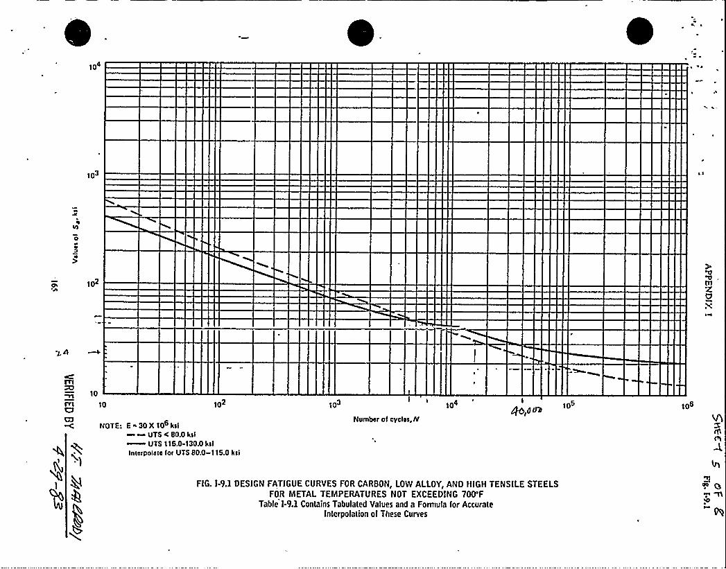
FIG. I-9.1 DESIGN FATIGUE CURVES FOR CARBON, LOW ALLOY,AND HIGH TENSILE STEELSFOR METAL TEMPERATURES NOT EXCEEDING 700'F
Table l-9.1 Contains Tabulaled Values and a Formula for AccurateInterpolation of These Curves

~ I 0'*
I~
1
"P
7 " ~
I

!(56
IIt' prone'rl La to use the tcnsQe strcnf~(or fapgttc Qznit) and, after deter-mining thc sec(ion modulus of theactual shape, to apply the properbending formtfla. However, b museof the diglculty in obttLining a
aningful value for thc tcnsQCen~St in tests of smaQ specimens,
c load computed in this mannerusually be somewhat lower than
the tsctual load required to rap~the ~, unless unfavorable redd-ual stresses ae present in the fin-ished ~
Ekongntion of f~ iron ct frac-tart ht vcz7 smfLI1 (of the order of
20
60
g,so Close 60
so
rit 20
Io 20
0 I 2 5 4stroih, oztot irL por in.
Ag. ZO. ~i stress-strtttrs caroos)or t)tres eh+a of yrtty frcra tn tctt-cfots. Efodtrftrs of ofdsti~ tr ttssssssrscfto fsobtts k, B oad C, rcprascntfsty W
of t)tc tcasffc ctrcstyt)L.
0.(Od in, per in.) and hence is sel-dom reported. The dctdgncr cannotuse the numerical value of perma-
] ncnt elongs,tion in any quantitativecr.
Torsfonal Shear Strength. hsown w Table 12, most gray irons
have high torsional shear strength.Man grades have torsiontLl saengthgreater ths,n some grades of steel.Ls characteristic, along with lownotch ttensitivfty, maRes gray iron asuitable material for shafting ofvarious types, particularly in the
es of higher tensQC ~ngth.ost shafts are sub/ected to dy-
namic torsional stresses and the de-Idgner should consider carefully theexa"t nature af the loads. Irar the
V)LAY IKON
higher~ength irons, stress con-~tration factors associated Trlthchanges of shape in the past are im-
rtant for torque loads~ well asor bending and tension loads.Isodulus of ElasQcity. Typical
stress-szrain curves for gray ironare shown in Fig. 10. Gray iron doesnot obey HooRe's law and the znodu-hls in Sentdon ls usually dctermiztedarbitrarQy as the slope of the lineconnecting the regin of the s~-strain curve with the point corre-sponding to 4 of the tensQCstrength. Some engineers uac'-theslope of the stress-strtLin curve nearthe origin for determining themodulus of elftsticity.
As indicated in Table 12, the mod-ulus of gray iron varies considerablymore than for most metals. Thus, inutdng observed strain to calculatestress, it is esaen(ial to measure themodulus of the particular gray ironspecimen being considered. The nu-merical value of the modulus intorsion is always less thrn in ten-(don. lusl as it ls fo. SteeL
Hardness of gzay iron, as meas-ured by BrincQ or RocRwcll tcsters,is an aveztage result of the softgraphite in the izon and the metallicmatrix. Vttriations in graphite ldseand distribution wQ) cause wide var-iations in hardnesa (particularlyBocRsoell hardness) even thoughthe hardness of the metallic matrixis constant. To Qlustrnte this effect,the miczohardncss of the matrix offive types of hardened iron, as com-pared with ItocRwcll C measure-ments on the same iron, is shown inTable 13.
It is apparent that ifany hardnesscorrelation is to be tsttempted, thegraphite must be constant as to typeand amount in the irons being com-pared. It is recommended that Brin-ell hardness be used when possible.
Fatigue Limit in ReversedIleftding
Because fatigue limits are expen-sive to determine, the designer usu-ally has incomplete information onthis property. Typical 8-N curves for
gray iron under completely reversedcycles of bending stress are thotrnin the graph on left in Fl . 11, tnwhich each point represents thedata from one spcclznen. The cffc:tsof temperature on fatigue liznlt andtensQe strength are shown in thcright-hand graph in Fig. 11.
, Axial loading or torsional ]~~cycles are frequently encountered ia "
.
designiug pazts of cast iron, and lnmany instances these are not cout-pletely reversed loads. Types of reg-ularly repeated sees'ariatlon ustt-ally can be expressed as a functionof a mean stress and a stress range.
'rlhereverpc+sible thc designershould use actual data from thc 1Ln-ited information avaQable. Wllhotttprecisely applicable test data, an es.timate of the reversed bcndiagfatigue limitof machined parts tnaybe made by utdng about SS% of thcminimum specif)ed tensQc szrtngaof the paMcular grade of gray izoabeing coruddered. This is probably sas.fe value rather than an averageof the few data avaQable concerningthe fatigue limit for gray iron.
table IS. Cow~ of ~~)) ~ncso of Gray Irons. as Inattontnr
by G~pMLe
~rtt C htsrns'type of Totaltosphite osrtroo, % tLrrr (s) esrtrdfht
A ~ ~ ~ ~ ~ ~ ~ s os csee(c) slJA ~ ~ ~ ~ ~ ~ ~ 2JS CS I SIPA ~ ~ ~ ~ ~ ~ ~ dz)O ss 0 (NLOD ..i...i 200 $4.0 CSJD ~ ~ ~ ~ ~ ~ ~ Mo cs'v coJ
~(a) Mcasttrod by convcazfoaai Rocttre2
I. Lest. (b) Hardncos of taatrls, roeasttrsdtilth atttrc~fal harness toots. Snd cott.
lo Roc)~ C. (c) Although tbfs'ra)uc sraa obndaod ln thc xpcddL teralated. ll Is not tyafcal of srtsyII.OS% C. 04narily thc harness of Miron Is Rococo)) C CS to SO.
An approxizuazfon of the effect ofrange oi stress on thc fatigue ))znilmay be obtained from IQagrsmtsuch as Fig. 12. The tensQc stwztgthis plotted on thc horizontal acids torepresent the fracture strength a.der static load (which correspond(to aero stress range). The reversed.
o Notchedo Ltnnotched
Notch consists of tronstorsohole ui specnheh diorheter
50
20
0 Notched specrmens,sness hosed on (tress oroo
0 tthhotched specirhehs4NOtshed SpeCimenS,
stress hosed on hei oreoEoch pomt represents one fothprs e'rhtt
Tonal to strontth
sos ~hi rririisrs „„,„,oe,ooorema Ml ~reset .... jdp04 orrrerlyyl Isiirr~~"".rrpoO err w Srere hieorerleee ~~"".so.coo er s ser cree
o Notched spscrmehs~ Unnotched specimens
Ecch point represntts ohs testIO
0e'''''umber
Of CTCt ~ S tO frdtrrre
0 l
o 2oo 4oo 600 aoo coo o 2oo 400 6oo eoo toooTostiht) tomperotrrre, F Tostiht l~ fhperotMre, f
+ Y clcrocs trait off~ of ~rt~tro oa forfyoc )frrsft of yrtty tron of t)tc tens(fcZJZ Bf, ZSS Zta, SSry p, yet B, equi Cr, yzy p t. Wr Ca. (Tr. ~ton Coulns and J~e O. Saath, proc. ABTh(. df ~ TST. Ipd»

p ~
MPIPIIIWPIIIIII
~mwwaawr ~~wwwww~~RarlSI~~RarrlE~~sarsBI~~RarSIR~MWKRSRII~MWRrSEIKWRSRrlBI~R$5$ 8~~~ERRIIII~MERRIIIMRhiIIIIIMRRIIIIIHPII!lily'%P)lllll
h+II)))HW ~ III~~warsha~~RarrsR~~Earssl~~Earr%$~wRarsrll~wRarrlR~&ERHSI~WRRRHl~HERBIII~KENIIIWESHIIIIWSEAIIII
~~wwws~~narra~~barras~~Warrkl~MHRrlll~HER%IIIHP)IIIII&.%~~wwswsmmaans.raars~WWk'r Sa~MKERIII~HE%III~WSIIIIIMPIIIIII
~~aarra~~Rarss~MWRSRI~WRSSllMHESSIIHPIIIII~~Harss~~%arrl~Mwsarla~&ESNQ~a <eIIm aaaIII
~IIIII
~~aarII~~&arrs~~~args
RPIIIII~RRarrll~~Haaksg~~warrH~MRErrllWEEEIIIa H%5lllllHPlliilh'

PART 3

Nuclear Energy Business OperationsENGlNEERlNG CALCULATlONSHEET
I -!0/~q
SHEET t OF
I ~ ) ~'E\
E
'NUMBER DATE
SUBJECT ~~ " . ~~ ~~ ~~ By
WQ fAlq ttdg ~g ~ gPAJ ~gtlg~dA/5
CC~&~: ~a mFFH.FO HHFS TTFEH H tO~FS~6'TO ~ PWFT +gev. o ~~~ |.~ feR. p~R PMi~K peTteoft'A C~R~R-
pJE 7> S'g4 Bcyuevte&s eye@. cy -yS+0 .~~<3 g~ ~K wlc ff ~7ww ~-ltd.~
~ J
gemeddg ~~ gZ~~ pm~~ ep7 g<~ ~e ~O ~ItTegi~ Vt=
Cgt M PON &Ptf. PDP ~ ~o WtUMEklgf ~~ ~~~ RausDPF + SZt-W7 gaia'emetaS ~P'CbVF ~yRqie, ~u Oyaa~<C- ~~~>CS
tRG 4'~0/~7 P0A) mog~g . MR17t'~ ~m ~ gy'Cqtdd ~QPools 'TNPQSTOtg~~~ h8'R>M, p ~, PEW'~/,~pea„~p gyd~tC
5'Cf, gad n~'4r1 ~WE gg& i~ ~wC
flV~YE@2 M '~N ~ 8 ct~ @f8 f~~AtS ti~Fy ~ ~ tfdd ~~t~ IC Ce4~e~mV E ~P d8 Ter~&
fg4H QHC dp5pMQ<K PQ~ ~FP-(EAkS.
%S'e~~tdac. ~gL~ s<~ ~4«s'r~ gu~eT'~-S aTTW gFSFETEeC. ETT~ Wg SEITFO q i TFEEE ~STEW < < " )O(ccHrea.c8 H~Hd ging 5f~D RT ~2$ -
~ QlVlp Mp ~~ ~8 Qy~~ ~g~ Gl~n ~<6 H~ ~~ tytyf.
„POESY
<F.IFiED OY
NEO 87 (REV 8/S1)

< ~ ) .<IaIT $4
I $ $ ~tAICt$ 0C4$ $
t$4CtAIC
4 ~
SS
ltITDDt$44«AD~4«%
$4T0IS $0
444$4C
t$ I
D I 5'QCrHZ~
DISC&~ tfESg ~AJC( gdgffSC/Cg(IT d
~>Top ~g~D
t 4ICt$4CSD I'lI
«4I ~
SD I ~T
SDI~ ~
SDI 4
IO
S«I S
SDI ~ IS
Stl $$4l t$4I ItIT«1
SO ISSO~I
S$ $ 't«AIAt$4A
IT«A
~ TE P <ytRr 68 AhK Dlh.PP sfhccE o9s8 /Jd(7$ .
~tlt
~ ~«AlC
IO ~
O gH8WC LoCevious ~gpgdrt1FD.ITDC
SltID
«4ICt$4C
ITALO
II~
ID
8W
C
N
8 O II 0
O
h
CtPV
nigl
DC
SDTA
l$$A
ttl*tOI
uaDE BY
IA
SAI IA4 $41t410t$40ITDC
S$ 4~S
S$44S$ 0'4

t ~$1
NUMBER
SUBJECT7(.bN
<V("QAJpgdevl
Nuclear Energy Business Operations'ENGlNEERlNG CALCULATlONSHEET
DATE
Mes Pl'(l(tt(6 t t Fo EvRC44 z„+ggt/6 qe ~ ~g~vleu~PA. SH ~: aeC~Vce gee nc.
o~ 4 c~t-zw ~ s=o . (- t ~q (7(y'J:.
&8 W Z~~T)|- M~g m P) Og( "Cl) Sad
4.0~Pe+ f3) - ~g,y ~.
I -tijaq
<~r ~f7woClt,lo2- l< uQ
5,< ~Qg:
~~< l7l
4Le~ ma, oeemwwc<
~tz
(7to hatt(got j ((t 9ti9 .AI07+
/ ~df. l>P»'t('.u ~~a g
'~ (Rt ~~+06.S-
/d) l
( ~) ~g p~),~W~u t~X l4" g /34')
4'7 to-)~
ps)'ttv
lt'dtt(cJ p~ XT~ ot~&vc&~ ~9 ~Kg /3~t)o(,
l3~ tt'.cp 's'((-(/gSr%
z7om p; ~7 /9$l( Cad 7)o-s&(70
~gttev(: cUods'h~lkHsA&JQ() 9o,p gt(- ~7oW PtJ Fee H~ )md dd hf~
NEO d7 {REV d/dl) Qg~ FtK't4L= ~god '
GXCD
Q7 LIJ
O

I ~ 4 E,<>EI
Nuclear Energy Business Operations
ENGINEERING CALCULATIONSHEET
'NUMBE(I
SUBJECT ~ 5 CQ.. C5 - Fllz T(Cr46
+0 S ~ ~gg<ES- g(yAJg
DATE
BY SHEET ~p- 'IT
3-. S .)
r ~I ~. WQCN?. ~'f 74'd ug
(3 CI-3
24/('t t 7'7~ ~v wela~z
'7'l('& 't
EI>3ECC +ZOCSTII(A +7$47 t&EQ+
SSI'T<S
LAICBASICS4I II
SSI ~ 3
S4I 4
SN ~
4-I I« IS~TEIEIEy FTEEH
~F SIEVING mn CEIITEII<EETC ~„~~ QT3CC<PHEIE (TIPS CIIC) FIC)CII
LTTC<a~ow,
R'~ ~p g~~(< ti(~ 0
~~+'('7<7 ~+37Z.—I (son= ~p.p. ~
SSI S
SSI IS
4 4 I 'S)4I iS4I ldI 34A
SN I
SSS I
SSO ~ 4ZAIA2SAA
0 f~9+>(
P'~ Pl F + +2 (~~7
Ft/M(3(M
P~ I k Ig
+-~ t~
P'(7C 3'79 W CS >33;7 gHIg ggC<.~
~ma(IS AJ~
L 77CE +IEC33$
<-~ g k'l
4SQ ITST'
IEz) I.
A(II
M7>V7>I5-
lsC 3
~~
R~ ~N W~~S (J(SM
5s&/ ™.~~ ~p StWatC. ~rye(~ ~~~ V~sy~~c.,W~ A/~ ~ crA/r(OAF'est. WT(dcv< uF(.'- gvemyT((s< pvs vs r uv ( m.
NEO 47 (REV d/dl)

~ I oi ~ 1'oo il
btHtKAL k C IN 4 4U.Nuclear Energy Business Operations
ENGINEERING CALCULATIONSHEET
I lg/ g
NUMBER
SUBJECT-:PVRt.dd tIM OUE '7b 5@V ~AJR"7
(k)~q <L-
DATE
BY SHoET~OFS'
~
s Y/4
pSi'HO',
~HM~
s~=
ts,
+7 7 st'< 2.75j = '7$ 35
Swa88 =
Neo.ar (aev are]}

t' ..I)
i -iS/zqNuclear Energy Business Operations
ENGINEERING CALCULATIONSHEET
Eo~gNUMBER DATE
BJECT % Vf'6P I PC@ 8Y ~++ SHEET~OF~~W~W I-t/W<H4 OVE ~y $ /4/ ~ele7I~Vi'HO
I ~>Cc Pd g.uROdt5 %0 g~8Tt C ~O
':PQ P-4Acig
~ --R -~+~. '4 9$ '76 M>~g 0 7II2- = ~34K+Pg zp~ l7 9 >o - WICgz73't~rC + ~3Ceo ~ 4 I ~s5
o~ ~l ~~we)- ~we ~cF~ CAW go~~ ~~ i~ ~C, bi ~g~
p + z a.~
ld $5144tp~gpg ~ j "
3~ >'>.R3$ < ~ C&89$
u~ —po. IrIg
NEO 57 (RFV b/81)

glq 1
)g
I
~ (
t
t

~y~
~ )i ~ ~
Nuclear Energy Business OperationsENG(NEERlNG CALCULATIONSHEET
l -li/zq
NUMBER DATE
SUBJECT:a'
~~
~
ave ~ s~.l4f~dE 5 fA~o: ~<~ 4 MA+Io l~ <~~ ~ ~p'. ~p
otto~'.Pt~WW~g~ P~~. ~~<~ PtMF ~~, &~ mA/~1~ ft"~
~mi'- oP .~ Ri~ tss g~ ~ cec~mvi i" ('wcv~ew4w swears).neOW S<~ ~ We~g, gy~-ty
Pgp 4 g~ <'/ f~reAI S tl . ~E 5,g~ tJ gtlg > ~ ttF
5'7awe. 4 ~ Pws pf4~c- vs~ C, 008, sM, v~g eve /&res v'~ u~sH~Vi>W<B-gd "~ - CR"-H~M ~< M ~J~, em~ Aa5L'4 PW5 gg4 V~Ceg~ ~ COdSta5Ae M WR &eTt ~at(VP Lt~ ~ gO CQJ AC-'WR It~A/S',
4
>sos pci g|~~ P~ 0 g~~ ~~ ~7iov r il)slee@ = .'~ x~5 - iidom
q.ie ~PA8 7 - c}g'(4 -Ng70
rhz~ ex~eJd Q+wxiiwevr~ )g = 'tilii P' s ~voce mnv~m u~iq,
PknCAW '~: ~ Id ~~t ~y~ ~ ~M OP-
+ 4g- ~go S ~>CH t5 ~~ ~ / tP4~~ause Rq- ~lq ~-T <P, W
'QR; '{pQ.<04 Qf7$Ai 9 f2-( x7 ~ g /g)
VZDE BY
yEIFIE91y4-7:,.~-.-==
NEOidl tREV d/dl)
~W&$ ('gg~t~, ~) m~ ogg~a&yt~cmz = ~, C~W<'f ~~0 m m~FeW, ~~«u
t7 &," ~ O's'H Rw Qo Ne~PW~ ~ ~1H 0~ ~<~ t s rJd ~~ ~~ ~~gq t ~l.~~gRg c'AA~V'hglc< p~p~ 'y~ ~c&pw~.ate< ~~y~
Ve + c.~~ 4'~,-..~a x~-.- gII7> Pfr.t ~
Qatccut: cdpJG.- (" AWCe~7- >P Pep 5 11072'h Ct' = ~ (e
QS~ Rec<iiP =.' tiiS'

CRUMB R"3,UBJECT
hNCklNF ERRING G
OATE
BY '>HE ET
~-(7 zq.
~~ fP&gAWK. Pd~ MP~cWggP'Pl
85
Rp ~ ~~-'- IQ 6@I
BoHL .
PLNT Q 175 j~>W Ae fo s:ran~ mo slav was'— ~~" 4 Iaaf
t IJ. (48
M~ —~aura 'r5 I3 Id. UB
L
<>br g5 l>9~
z.$ 8g t Eg J ~a5KN w33
|"g~uLp,<E <fee'SS AV NilX. Col A
~min. = .~< " +"'4'~
>o ZW f-SS - I ~ = 1'5. Cc
'l'E lg —ZX.7G g. l |' „)7.rgb
ISSUE
>iCf
Sus. CS P/~DRFZI-27SECTION 5. 0PAGE BS OF 104 ;eoE 8Y
y-~-63VFRlFIED 9Y

'l N~ )
~ ~
~ 'P

'f '~'- lS/tR(Ey SEE
AUMBER
'UBJECT
,)
t
ENGINEERING CALCULATIONSHEET
lo CkDATE
SHEET
pJ.i ~~. e,
4 6~~2.3M
5OO X. h1 92. (I $ g95 y I~ g.
4 ~ - 59 z. w LS5 Sss.s8'xy
Sr-'5-,CRo + ~<5 4 ~b
zq'~1
pg,. 573 C
PET'I2. 4eum
2-53
ZS-38
PgIWa(Pg I S~~-gETy-d~~ + q.
ESSE ~ ~MB
(~+38 ~4
+ ol~~~i~ I'~V~ ~"'~ "P / E= ~P fQ 37K PSPgrI~
WE'frdVMBF 6JR . USMC p= 37~ pSt
svs. cs prmDRF 1-27SECTION 5 ~ 0PAGE 70 OF 104 INVADE BY
'ERlFIEQ BY5 -l -gS

NUMBER
Ig fJ ~
USJECT
c"OATE
sv
c.I~. see.SSS >i& .
ENGINEERING CALCULATlONSHEET
]oI E 0
SHE" T ~ri-~ //z.q
zy. (.sc —- l 4 = I2,.89
Za- 7C
l t. 46
C to~-5' = z.z.qs-
Q%o -$0i
W01. il Lg f<R5K i2 E~
I 2 x. $ 2.'7 22'g5
'z {Vo + ] iso
!ec Qg Zp P Q~
= Apso PsZ7+~
rgb~lyq
22.$ CSUS. CS P/NDRFZ1-27
.SECTION 5.0P AGE 71 OF 104
;,<CDE. BY
VERIFfF.D 9Y.rP'

~~
~ ~

ASMBERI
SUBJECT
ENGINEERlNG CALCULATlONSHEET
OATE,~P1 z%<
PRtVClPA,L..WgESS-
"I9vo g
+ ~zb.
4R 70
Xt4 +e,Rise ahSE.S, "I'BK R, P>, g>,
P,P 6, l-Om+P- TttAQ TOP ~Cg SC l'HK~ iS, ~ O
p' PD>Yl0$4R'L 5gf;EsG c&LcuL,Awol gog.
N4zs c=AsZ .
+PJl~daK ~+ y, QD,(f5'' 7', ~dg Psz
SUS. CS P/NDRFZ 1-27SECTION 5. 0PAGE 72 OF 104
..geE ot g+-l3i'ERitlEb8>.~

I~
~ gl E
I
Nuclear Energy Business OperationsENGINEERING CkLCULATIONSHEET
I -my~~
NUMBER
SUBJECT I
Q/~h 1AM ~ -t0A~
I
p„- ~4+79 =~>'= 4fq fVWb=g- On+ 9'>-
uY7~~9nx
DATE
~D~MLS''ft ~g
DW- + ru->7 W < I9)I
"tw«3~t'+ +—
)C $7< I 0'f$73 g~ 75" +Rg l0>
+w 2M3
%)e IR ~
3P~ P 5i'pss
P «Cc wl>'Ir
pc. 4 flLg~1
I~+yr /<~'3,
sdt9 gp I qy - dr% 8-7
W TACO& a&~ Qg~Y~WpJ~. g grJ = fO,ddt
(~d~ ug~ ~tea = —~ d-YC C f,
(O,OOP
3 3 dde )4$ lI
Neo e7 raev ere')
MADE BY
>ZR(F(ED PY

<0 asumw~Beaver;
IO4
'1 03
102
10
10 103
Numbsr of cyclss, N
104Qb,drJ>
NOTE: E 30 X 106 ksi~ ~ UTS C SO.O ksi~ UTS 116.0-130.0 ksl
Intsrpolste for UTS BOA)-116.0 ksi
,FIG. 1-9.1 DESIGN FA I iiui iuttvta 1-UK l;AKUON, LOW ALLOY,AND HIGH TENSILE STEEI.SFOR METAl TEMPERATURE T EXCEEDING 7OO'F
Table 1-9.1 Contains Tabulated V a Formula for AccurateInterfsolation of urves

~11~
II
J
h
II
V'1

?0
60
550OIio
so
r7t 20
Io
Cross 60
40
20
00 I 2 5 4
attolnt 9001 lb. pef trl,
plfl. Jft, ~ Mesa-ctrctta ccrpccfor three cfosscc of prttv trcta ta tca-cfoa. Nccftluc of cfcchcftlt ta tttcnscarocfto Jtctftttc 4, JI aacf C, r~ceca5ap lrs
of the tcacQc ctrcapth.
in. per in.) and hence is ael-ported. The des1gner cannot
e numerical value of perma-ongaCion in any quantitative
er.sional Gh'ear Strength. Asln Table 12, znost gray irons
have high torsional shear strength.Many g.adcs have torldona} strength
geater than some grades of steel.characteristic, along with low
notch sensitivity, makes gray izcyn asuitable material for shafting ofvarious types, particularly in the
'grades of higher teneQe strength.Host shafts are sub)octed to dy-namic torsional stresses and the de-signer should conlddez carefully theexact nature of the loads r thc
dom re
ncnt el
Totshown
356t
cn is to use the tensile strength(or fa:tigue Omit) and, after deter-mining the section modulus of thea"tual sh.pet,to apply Che properbending formula. However, because
the dMlculty in obCcdzling aanlngful value for the tensileeng'll in tests of small specimens,
e )ted computed in this lnannerTri)1 usually be somewhat lower thanthe actual load required to ruptureChe pert unlca, uzdavorable resid-ual cresses are present in the f)n-
gart.Houmtion of gray !ron at frac-
ture is very smaQ (0! the order of
VM,Y l'RO'.i
~ezwtrength irons, st~ con-centraCion factors associaCed Tyithchanges of shape ln thc part are 1m-
t for torque loads as Trell asor bending and tendon loads.
Hodulccs ef Elasticity. Typicalstress»strain curves for gray ironare shown in kg. 10. Gray tron doesnot obey Hooke's law and the'modu-lus ln tencdon 1s usus~ determinedarbitrarily as the slope of the lineconnecting the origin of the szzess-strain curve with the point corre-sponding to 4 of the tcnsi) eatrength. 8ome engineers use theslope of the stress-strain curve nearthe origin for determining Chelnodulus of elasticity.
As indicated in Ta.ble 12, the mod-ulus o! gray iron vazim contdderablymore than for most meMs. Thus, lnacing observed strain to calculatestress, it is essenthQ to measure theznodulus o! the particular gray ironspecimen being consMerecl. The nu-merical value of the modulus intorsion is always less than in ten-sion, just as it is for steeL
Hardnccs of gray iron, as meas-ured by Bzinrli or Roakwell Cesters,is an averal,e result of the softgraphite in tlte iron and the metallicmatrix. Vazilstions fn.graphite Idseand distribution wK came wide var-iaCions ln l sardness (parCicularlyBockwell hz;Bless) even thoughthe hardnest of the metallic matrixis constant. '].'o Qlustrate this effect,the znicroha"dness of the matrix o!five of Ilazdened iron, ss com-
vyith RockweQ C measure-ments on tht: same iron, is shown inTable 15.
Xt is appian,nt that lfany hardnesscorrelation is to be attempt&, thegraphite mu f.t be constant as to typeand amount in the irons being com-pared. It is z I commended that Brin-ell hardneaf, be used Tyhen pocsible.
Fatigut Uysit ifi Ilevoysstdl4sdiftg
Because fl.tigue Omits are exp."n-aive to dete:mine, Che designer usu-ally has tnfiymplete info~Cion onthis proper'y. Typic'-N cuzves for
gray iron under completely reversefcycles of bending stress are sbocTIin the graph on lett in Fig, 11, inwhich ec.ch point represents th,data from one specimen. The effccttof temperature on fatigue limitantiteztsi) e strength are shown in theright-hand graph in Pig. 11'.
Axial leading or torsional loatlingcycles are frecfuently encountered icdesigning parts of cast izon, aud iomany instances these are not coat ~
pletely reversed loads. Types of reg-ularly repeated stress vaziatlon asti.ally can be caressed as a funtUctnof a mean s~ and a stress range.Wherever possible the designershould use. actual data from the lim-ited informaCion avaQable. Wltbotltprecisely applicable test data, an es-timate of the reversed bendittgfatigue limitof lzlacbined parts maybe made by using about 55% of theminimum spec)fled iensQe strehgQ1of the particula grade of gray lzoabeing considered. This is probably ssafe value rather than an averageof the few data available conce~the fatigue liznit for gray iron.
Ttsbie XS. Cottstarboct of Qockstcll Ear4-ssctto of Gray Zrona. as Zstnttestee4
lrr Gtalthlio~IIC StotttsTer of Total retd ae.Ctspbitt carbon. % suw (e) oorttdfbt
A ~ ~ ~ ~ ~ r ~ aj)IS 454(c) ClkA ~ ~ ~ ~ s ~ ~ 254 4SL Slka o" ~ ~ ~ ~ ~ ~ 4'SJI CLOD ~ ~ ~ ~ ~ ~ ~ 240 a $40 CSSD ~ ~ ~ ~ ~ ~ ~ XAIO CS 7 COS
(a) Moacttrocf by cccsecotlcmal Rccttta7C Coat. (b) Ha~ of uautx, soear ystfwfth afric~ haloes ccssccr atsd coo.Vorced SCI ROCktren C. (C) Alt~ Ihhva)tte seas ob~ hs the specific IcuCSIOCI, fs ta hOC tyPM Of Cray Itcct OfS.(sft% C. Orensac1ly the ~csa of atchtreat Is F~cil C 4S lo $0.
'An approximation of the effect ofrange of stress on the fatigue llznftmay be obtained from diagramssuch as Fig. 12. The tensQe strengthis plotted on the horizontal'xis torepreoent the fracture strength un-der static load (which correspondsto pro stress range). The revezsetf
FottVw Htnlt Tensile atstttyth
~c
~t IO
e Hotched0 IfntOIChed
Hotch conststa of tronstersehCCo ~t specimen dtorneter
Jef ~l» ttt~ls .......eo,ioo eNnotice Mr,~. ~ i ~ eopoo eot~et~ I<est ~
~ettaoc. Itpoo est ea pete ~rtl~ ~...COW et ee art cree
20
D HOlshed Spestrn>~stress based tn press otoo
0 Unhatched spoc<twns4, Holched apocimtns,
sltoss baaed on not wooKoch poet teptrsonts otto foti(nto litnit
o Hotahod speciotons~ tlnnotched specimens
Eoch potn'. represents one tost
loa IO IO to 200 400 600 800 Iooo 200 400 6oo noo ioooHMmber OI cycles tO foihtre Test tnd tetnpolotUte, F Teatinc ternoerotttte, F
Pic. If. S-yKf~ a4f off&9 5/ tests pertctarc cta fcttfcrttc Ifrnft of ttnav Ircttt of thc tcrteffc Mcafyth shctcra. Cctnsccftfcra: ZA4 CXdt af, JAS Xa, M7?, SJZ 4, tJJ Cr, tdp NI,OW Ca. (Vy. ~hsccs Ccuuts actd Jacsoc O. 8cofth. Proc. AfrZM,dl,vs7, ipcf)

103
102
hier. nomlnelslrese C 2.7 Sm
10
Max. nominalslreee ~ 3.0S
cR
Tlrn coC7 1.0
101
NOTE:E ~30X 100pei
102 103
Number ol cyelee, N
104
t
4r
FlG. f-9.4 DESIGN FATlGUE CURVE FOR HlGH STRENGTH STEEL 80LTlNG>+<Ilttcc; AIAT r:Yf'cf+!err''
Table l-9.1 Contains Tabuiated Values and a Formula for Accuratefnterpotation of These Curves

I GENERAL ELECTRIC CO.
Nuclear Energy Business Operations
sUBgECT SUS . H <T d& ~F 4<(A gY
&Jr(L48 7(dd Ptl6' $ g t1 HC<0rt t(d>S.SHEET OF
&'O~IJ(g~
Qg(qt~ Qd~~((jJg hfECE ~~5'7Q7 gtf5~ ()peed J
aWo ~a<e$ 4~ ap ~h,( pu~ Ga ~pnP&Pf<.wee tTo~ Halo Dsw< edlas
Q ogg~g, PM( foul geg4 ((tdt1$ .
Mh>Q P~ I( )&fKfget5aOS18R. )E~P )EOESTFFS
5 +OFF/ (F(IFT(F FHddFdTFFFFE tHldf'VS)(HOU(HIT(dec. fi9dfs
M~pog p~Agwzo $<lwc mao Dp«" ( C pE-'po'('P<
c p(((lw) ~g~x(r i~EgE gals-v go ~Lcd~~Z Z<~ f~('I M( 4'(I.HS'e~
C& Iv(cddlc Loc<g(ddddf ~pots& sptc ff'>Ps OSA7 I+ ~+~ d '++ fs(~ I~ f=- +'I
P(s(('((dyPJ 7/PC, Pygmy Pfg l(~Q 4)IPPC 1(0AI~ H'ERE SIC'(H(( Ft(@34'A "/ ffI&((C Y<»d~ 7(l<
~IeQK Ppr.yg~ C SEC WV7&PCP l(-'c:sP( N'S4 SPF«(.('.'r'~(')
&~or((. $ (i(. v(od eat O(S'C&ef<.F Ad'Ez ~ Ldr(m~ &III ~( l ~~ ~~ 4~ 7oA+~
< WC Pi t)S f g g4 %PC 574 r(C <~4%5(g.
Neo ev (REv e(es(

a ~t'
~
'
0

F itE
GENERAL ELECTRIC CO.
Nuclear Energy Business OperationsENGINEERING CALCULATIONSHEET
NUMBER
SQ. PI C.g 0& - Fp "rggJ+
GdR L4R VI44 P~G f5 5 gQ 4 ~Oped S.
par Cg
BY SHEET OF EP
l. B((a55ee v~ (Hdw fsa~v (E oft; ((EEPP: Oap+85( re,~ 4"-()at(tdttttFTTOF g»faim te(O Za 5»FF7(d V Ssyet. teraS c U a(E.F(
MQgr8vsrff4~ 0$wc'HG ~V~ c~~ m~ ~pyMiu ~~~~~ ~~~ t~ it»J
PFK70g 5F- cP p
IPtox 5~wo55 - (sq~P xdP =d sr(c PE(~
~
tft»exttt(Ptd(E s<(EoE( 5'r = ~+~'5 = b(Ksg late'.
(T(ts»Q(t((v: gtT-E»7 re(p (5., cuÃTH*TE METe6 sgqeFEreh = Pae,doo ((sar.')Wg(dae(ia CU(ait8' ~ gdr-8- ap(r)e((Whirr
re. C~.= r( SrS ( xl = (<ooo,Ctrees(
(V( P(T S FT('aa Ho lA7 5F((avd 8»(i (S '. ( Pep'F(g 8 e5(-re( 5(ar .O„.()
WtWttl foft SV(soda gU& YTT srtt P(c Puts t(iPXt. (d (TD5 (+('F(9
Qe dbd ~ . /gal~ gMax~E Cd~JB~5~ M~i~(c( c ~ apE ) rof-'r„-- M ada les (v( >a,ae(o 's(to.tof („ae taava.
|l CI 8. l9((N'Vg? (tete EgO518t.:illr ~ II(e
CRL t((ttsPPD E»(SCWv D(so fe 5'(T(C H. Eat I/. ltst(D5 (D, +Irk~dr~Ve~<v~ GS'tace, a~ ~otP sf~ v'e0( p>p Spy +<444 SYgEH
eve<D ~ rv(ETox aF op (r ((terve(sex pE(trsvttu isevoHvstat we TSE PSTG ptts»E-)
/ ~
I
NEO.87 (REV 8((81)
] 5»EesgxeE5 = ((ser(w ,x + = +I lsd((5T'ftw~d»(~
ST PE-s5 = 4H5%
Nts»reaiout: P(a1t» ts-KC F(Eo(IT fi8»((a((C CJP>C i', SW 5'(T l. 8 OF P)lea u„= F (, 4=ee,- -"F* F ii
5»se f(c'F(r''» Oi(ev a(atteua(sis po»Spa(istud» Q acus FtEH(FIR vpp +go75 EE-rsassattsttsvivrof IHFsx ~ p(EII(eettFe ET Eats Iie(ato ete»s (E»THEEceeeet .N (x vppt~(pre oa<~ pipperz~,
)~654~: gIy~ ~qQ~ g-t~~~ Ig ~ <CPU
Pdds»E(E la(~'ls leo~Tea(- 5~~ c(5(a TJ= SFo» D(eatao (rcatsedeotet((~3I
t(
E((euE)
(;r'R(R~D8V ~~'+\'I

~I, ~ I
I ~ I ~
Nuclear Energy Business OperationsENGINEERING CALCULATIONSHEET
NUMBER DATE
IE44LCJRN(~~ SF'O SIE'-0 a~VV< ZID<S .
SHEET OF
t4h Ld P4~P WOt)IPtQ~ Pod f:cFizovoFT<EIo qziEc~ ~ I9IIo iFE Ef = sT'Esic. FFFTIF Pqd+~is-
FTJITSFT >IS POSEFOPFTSOO +. gTFC. TJ~OOP-, TIPS < EF74-@47-I ). ~ FTSSsIK
Sg~ Ig ~ P ~n t OI- Ptc+O Wt / HEI'~ F ~ Mg PS<> I'~Lc reps. DsIF ~r9 9I c. H~ Q~ ~ THE Qf<00g. ~ +cga P c AiWVf IIlQ,~Fe.
TTTIT i HsTO SPA'CUSVE ( SHOO SiTEH'MS TH,7, Q OI
gP&.ay~ ~~ si3 we Pcw~'~QsfRGJUf ~< ~aa~N7 sw~H . oVC %0 orcM~ QGd
Co<~+Rwi<C~ gs < ~w +AVE~sHI~~ «oc~ co«. F oTOE OF ~
P~ s.-~~ = I't'tl < ~W = T9aV~
g~7 9 ~ '39
'csin'h
<Qs+c W5W ~IS ~ WC5, ~~ ~q~t C~~ CSh'r r ~BY)//- eovo etio~ .
E Coy~GP PV~ WIiU~~1~~ fed%:CFFOEVIFF~ Z~~~ IS E7S PS- FFHIEFT iS LCF«»< ~i-'~ YF™I
MtJ4514 W
c FFToi'-TIFI~"Esy sIoc y= g;oo'o cilosET Cool FsoEvB cFFsovoivssg
VERIFIED BY
'eNEO.87 (REV 8/81)

r ~ y
'e>
l

'I 03
102
Vl
I\
o0
Max. nominalstress ( 2.7 Sm
10
Max. nominalstress 3.0S
1.0
101
NOTE:30 X 106 psi
102 103 '04Number oi cycles, N
106
FIG. I-9.4 DESIGN FATIGUE CURVE FOR HIGH STRENGTH STEEL BOLTINGFOR TEMPERATURES NOT EXCEEDING 700'F
Table I-9.1 Contains Tabulated Values and a Formula for AccurateInterpolation of These Curves

~E
~ ~
104
103
0~0~I
102
10
10 102
NOTE. E „30 X 106 ksiUTS ( 80.0 ksi~ UTS 115.0-130.0 ksl
Inserfsolefo for UTS 80.0-115.0 ksi
103
Number of cycles, N
104I 5
pg,dfra 106
FIG. I-9.1 DESIGN FATIGUE CURVES fOR CARBON, LOW ALLOY,AND IIIGH TENSILE STEELSFOR METAL TEMPERATURES NOT EXCEEDING 7OO'F
Table I-9.1 Contains Tabulated Values and a Fornfuia for AccurateInterpolation ol These Curves

~ '.4
~I ~ o
~r lx 'r~ ~ ~
~ el'lo'eI'I
I (. o'~ I
Ii
e''I
I I I ~ I)
~ ~
e( 'I'l)l'sf~ I .1(s si'' ~ I ~I'
~
~ I >
I I') ~ ~ ~ I
I I I. ~
I le o
I 'el I.'I'. ' I I'I"(I::. '~ ~
It ''il~ ~
~ ~ I ~'
(I I ~
I j) ',I I
.I' ~ 'l s II~ I.:i': I:~ I ~:I i:(s !( I, ~ ei
~ )I ~
~ o
I.~
)
3 ~
h«e os e sjl' le
~ ~
)s 'l. (o '.II I
: I os,
> e
l(iI::o i )I Is
e(s
, ~ 'Is' '~ .'j - I: ~
I o ~:I (sl. I e II ~ ~
I 'I '!s 'I'
~ I
I I 'es I'oi '
~: (S. ~ eo e)e ~ o I
~ lseI
e
tD
'I)~
i D(,o
I o~ Iso ~
e,)I>ei I~ I
,e
ss
e I I o
ol I':, I)(. I:).el''e
e
o ~
e
e ~ I
~ I ~
I« I o: i)I)Ii: ~ j ~ ~ ~ I
I, Iso'
I I Il I':. ll>'
~ I
~ ~ ~ ~
~ ~e
~ ls~, I
>e ~
II
~ I ~ I
~ e
sl ~,
i ' s ) i ') '(' l (
)~
''.'ll I ) I ~
~I
~ ~ s > ( ~I
o I
~ ~ 'I st "'. !
e
! I ' I I I ) :e: i
I lt I ~ e',) . ~
)I;;iI
l~ . j I I. I
e!': ~ I, !
(I sl
o e'
'
~)
-t)s I ( ~
.'I
I ~
.I. es I' 'I
Tl(, ' '
II ) '.s: ~ I o> 'II )(I ~ i il
>i'(l
t fl
ej; ..
sl: I~ ~
~ I ~ ~ee
!I 'I! l
:Ist
o sl
e
I I I)l 1.(!II I ( ~ I
I j(lt~ )
)~ I III:II~
It ~ . (Is, I
fs
~ I
Ii '" I
~ I
~ )
, ~ I
,I, lo~ ~
"Ie I
~ss
los j
I'IeI ~ i
,I~
i) '!e'
~ ( o.
l! I i(>j s.:
Iljl)~'
~
o I 11
Is
'i)l )Il! Iij
I jjiej~
I'l >I !: I 'I'f
(~
Is .ot,o(.
II si(
'P
e ~ ~I'
ols. ~ I
II o

IE
~~
~
'V

~ oM ' v e ~ ~ te.eel(et'CIIOTe el. Tv Sl LA; Aspc. 4 ((s( I(sess( LJ(t((so(st
'e.".C
~t ~ e
I~4
effI . i ~ P~)~P. + p ~
jl>es
~ I
~ ~~ ~
Is
~ ~
e~
~ I eel~ ~ ' ll ~ I ~ ~ ~
~ ~
I ~ ils e
~
) (
~ I ~ '.~ ~
~ ~
s
s s
'elill Ij ~
l
.sII
s
~ I~
~
s„
I ~ I
e~ e,l
I )ll s ~ (( ~
~ ~
I')e
i'11
~ ( ~
~ (~ ~
s I
IIs
I ~
~ I .II ~
'' I ~
I.e
I~ ~
I~
I I ~ I
sl I,~ ~ ( ~ ~
ee ~ I lee
i'!I ~ ~ s le,
; ~ I
( ~
s
~ '
!,,sl'~
III
II~ ~
(js
le
I~ e
I ~I'~
I
ee
Ie
,e(
~ I I
~ ~
I I
~ ~ Ie ( ~(el.. ~
I, I''', slI 'l
e('l 'll jl'
'~
sll
I ~
el
l ~ ~ l
's
,s
'll '.. ~
I .'I i. I:(~ I II(
~ ~
I, ~,I
Is
s
i.e .I (
I(l ( I ~
I ~
~ ( ~ (sl s
I ~ . ~:I
~ ey
~ (s
e, s
~ I
I !!'l"I
:( ~
sl
Ie)
e,~'s
~ II
~ ~
~ I
~ (
I, ( ~
e(
~ ~ ~
I
s
~ ~
~ ~
~ I '
~ ~'. Il-II~
:Is,'s
I
si!:i.s! I
.! (le~ s e(j
~ Ij !(l
,es
je
~ I
I
ee(
. I j(I 'I.!Is
' I
!I!i '.I1
sl
el
sl I )'ess
III .s
(I: s-
lsI: .II
Is ~ I I ((:s I.I . I'. e
~ I
:) ~ ! ~ ~
e I'.l
~ .
( (~
~ ( ~
s,sI
I ~
el;I I s
I I,'('e(e
I I ~ I',
~ ej
'!(I I l lle
II'II'PII
s
ls 'se(( ss'
s IIe'l (
j ls
el( ~
s I
~
lj'lle
e.,le
~ ee
Ie
sjl
0 V 0 V ~e ee o v o ee 0 0

I
~ e

DATE
GEHERAL ELECTRIC CO.
Nuclear Energy Business OperationsENGINEERING CALCULATIONSHEET
PCZC- PuTT ]-~ .
NUMBER, ~
EII< L~RTV'~ PtJF Za Sg g PMUHVlaAJS.
i -Ss.
EHE ET~ OF~&<'~F ~I 'E C~<K PM Sr~CIJ PE5Z&4~E4 QW PW'5 0 3'g'+'g k'g Pg EJ~
~HI~ ~t t 0 FoP PE'EFdg~i>J~ FAIT(caJE Lig& Eu'wt.clatter OdE- -t0 5'g VE8VC |
HCtdnztd AJS ~y ygegs'tm.A B~JJ ChC
teak
wt $H, CFg78 (d CP( f( c ~C LrJcn TresWC'P6 SE~-fFg7 B~EP NW ~E ~ ftJ~ SVRE&$ V'H~ ~P ~fJ7t < Ii'i- ~F ttlE~+pl+4f'C. Ferry'' +ulJ ~o~&J<$ uC~g ~~~pp ~~ qHQ ggF 4 55(-7Z.
Qtf(CQ Cd47RI<< Cd&pMV'E'+FEt~(~ pypJp pyrJg~lC grdg~fFf Fdg Pli 5'tJD)C..
Cf ~tJtPWMV, ~67~C L~g yak+ p~ SVCndV W4D OIS~W~ ntraau:.. (~kgfaIECli6'p
C. t™ ~~4~/ PI <+ UP< >~~J n Oyde~tt ~t'/Ca a$ 'OCA, SSC . HIJfl $ f'0
Lellllr ~i'rit d>Qr t~ <wc w+ldwsts .
~t: FOMP~IUW ~ OMC $1PC < < ~R t«QS &CPG EJRVJll'i:-
p~~.p porn Pdw'>~ ANci<t,'. (3d(7'$ .
fn~gilti.J< Fred wEce s,7r.g<'5'.
O'J~P pc~t 5 rn i
gO 7P; gq~tJl Vn tZu'7 g7~ y<C, Co~J'g Q(CV7I.CX Prude nmF~EJ.P~V YeuJF C'dE ra S$ 6 +SPJ+tJJt~
p'fVdnFI«
WEEI5 P( gF i-:>g EF>.+1g tP; F ilW,W~C EFFCc E S
VERlRED BYg ~ ZP
NEO.87 (REV 8/8])

i) ~ ( g ~
GENERAL ELECTRIC CO.
Nuclear Energy 8usiness OperationsENGINEERING CALCULATIONSHEET
NUMBER
SUPI
OATE
lptic Te 5'p V A<.%MAYto~r.
SHEET~0
fthm P Po& 00HnJ SU LYg:
<"RI.Nuwzu T(r.(st< SA<-.-SS — S.,t,'t',~ f 5t.
C F-'ep. OFF tt eSi 7.z-, Foo s.i.).PBc fl5ooE o7posx w /k A pEsoz1 oF' o8.Q.o pz.o . 3.n g) Ho( i;..
a".r'cf7:t<+(,r9'~B-t gg77dil UyQ~ @)g ~HTtc, P4PX. c-~5(ppftggg gd<. frtptd«CI s" xct I> =d i~c'I gt.'t. g7zw<~y tt.'S) g<.<g<qr~ ~yt<'c-.', = zc', c < ~ ].."
P
Q S<.C $ 7"f8<HCP CRI.<tlCl(7(M 5(tIo+ Q 3 C( Qp (I )HPPgt <cc S'Y(tc'vs Q'Pc&)l gW C(<t4 f~rtc8 ~t= ~ ~g gd~g
Polio 57/oos — zo,@zir z ot &'2.,o 9'2
/3z7c'Palo'fl<oo $ TRc~s I o,"- o '~ ~i zoo logic,
8>I.7'trtanP(e . Cg-gleet
PROM FnT(~E afgYE'„gttT II eF «.)g = gazoo Cqom,
I
A~cH<t R
WI.~arCu SVresy = lS;ore p5' ~t ~7«t<(t~
~4cci~7(dye'c<,75
5(t7: g tr d f- (! g.~ttttt't-"/(<<- 8 7'PE+5 < E~C'++7': 7(d J Ft(c7(tlt. of-'-
(zoK SOÃooS= ICozz x+ -.:- bo,zotjJL7(.'l'8JRY'i8lk 5<(tcoN = "- = ~ -
3l,tcR'~
rt
8dI.S ~II<r-l'.(~: 5n - >4'eat< p~~ct.-tI< ~pu< QSi<V. (p aI
PP g<= gC:,l<tg Pc p,J~ /tr,<Id'f.t<a.
+o'( f)o/C!t<g
g/ttIC< <rd Lr ~07'C(<t >t ($ >e "I I ((u'I/ S (PCi~(I /~g(<~<(E COl'tlC 0/I f. Ic;-r I I
Kez AA.I'ggQg p''CAj 5- zc -b>~
I/ERIFIE." 8y
~ c v'g„(t-.
NEO 81 tREV 8/81)

GENERAL ELECTRIC CO.
Nuclear Energy Business OperationsENGINEERING CALCULATIONSHEET .
VERlFIEO 8Y P~NUMBER
BJECT OCs45 L.iW V
~oa &J8 Yo sM dc-cVevtd&.
~ 5 Qrg,
Ejm HO>D PO rJ 8mYS:FOLgowtdt/'o~ wF$'E
Om< ~S t-7~, ~-~-I .i
<74TA I
~ parr)pCA
S/.<'g
ggo
F - P
q -.. I'I 2M IV GlH
/8y= N~ == I7,atb « ~
PA AI0 Q9RS5:C PVt fd 5<pv &M
Ng™I=
3(60Cn755
4.PI7 ~i i
'i
I3 ~ /hJ ~ ~. II
LO4p5 ~N ~I< ~
AMVE Pydd&<C- Le~ @+6
P.~~ (1F 5 0 $ HOPAW. MO 3.o $VEP-7 A~aff-AtId 4
COQUE I~g.l&Cc e ref 5'W
I= ly+<SI~/gc sS
~sC/0/~
pygmy
iluECEld Yiiid - ii.d7g$ ~~ ',, F~ lih"<X
+gay. $ ((+QQATTOQ= 0- Iz P~ I
g p~ipoH K5VSIQ(/- SZAZie. COe&l(~ ~<We
peg)e ga gg ili@g J.5+ii.(2, = O.it'8 Q ;CiNceggs'11MEVf H~PViiAG).
I 9 gg A~ M llM AM I~ PaweaJ6 MKdM<lo» ~:~
~
~
g,, ~ ~~ x~IyC = I~I ~ ~, do4x I370$ = f~~3>O
P~ -- Oe4, X A4I7 - X7> m ~" d'a4X la Cr5
7$@,=~»- W. ~= .0
NEO 87 EREV 8/81)

I~ \ ~ t
'

I ~ ~~ jt
GENERAL ELECTRIC CO.
Nuclear Energy Business OperationsENGINEERING CALCULATIONSHEET
I
NUMBER DATE
I - - * /p/ To sp Ii HcTvh rlaUS.
SHEET~OF~
P ~ ~O M~m~S ~ ~ VS'W.'ERG t Svkytc. + Sd.v VePSg:
3~X~ y 'I&4 p,S38
Q = g to,gdd f;+ d5 — tt,vd5Q= g - z,z7't+,z-v7 w,ar W
Ig,a~o +'V» - guoA->INy= Mp~ 0
I'p,BIO +'A3 = I71 I'>3
~l'IMQG Lt~ c4fxvM40J
'-
o UV ~U ciW +PcE
T= Fy+ —+—~@8@ ]g g@+
>5; 30+2-S; 3oW-%<Sitd dVdddt + ~ = ZO t"o3
P~'cf-etidddP'~gJO~ C -'~~t IJy~iD~ g~~ ~T'PEP ~„~ ~~g7S~~<t-l Go~g. Pgt-"; P $ M SPC~ R~ t.5.z.
VSH ddt 5 tdddd
za38 + z,S3$ =3~d7'I, ww7
5 a]~~4p
f,2.z,7 C~
tJ5&r Ae HI&4'
~tSd«gd-
AC(.eH&% 804,7 Spent'M t+ p+5'|", 5'W. HC (J-2 76~c8 /.~ x ~ t:'FoW WL-T l ~r~a~;fEtlSILC fgd'dtd = dtO ddd tdk
g/<dodd ST~M (J ddd
NEO 87 (ACV 8/8l)

III ~
0

I< ~ 1
GENERAL ELECTRIC Co.
Nuclear Energy Business OperationsENGINEERING CALCULATIONSHEET
NUMBER DATE
UBJECT 5~ LC ' V+ TlNG t &5 V/ill/4 By<Id4 DOG -fb Cpf Rc~VRnoAiS.
SHEET ~OF l
p /Jdpd gIform+
S 7~ CPg.Q/~+O~D:
FowÃdce Q~ ~/HE waefd pjzee ~ ppf-'f 8'5(-72 . ~Ps& repsSSif T(C C NdZtG to~/ g~ O'TJ ~P 0'/HAAI&'A/%S.
gy4y~a tp~ Wc~ Imp&" ~- '>.a -y'. Ho~po~rC ~s 3.o ) y'Beg ~Cu C~c(~ WETHdg WW U~ ~<gee -eVM ~Pr«
f8~~~ o(' evnea Dyd~(c ma(.yeti mev~~y.
5'+Avg, ~~ = 7g'pC'
Cdn/S(pEg./dm dnlQ %gal Ld~ „Pre+= AoQ Red<~ ~d V4CTl~ +aetFMTW$640& ~ Q,OTQ
$PbP(5. ~g (R.P V~~(,~ ~C~C+ g~.S('~-IC+
ed&'8),5'g-0 Le&g ~ lK Qm ~ (.Gy o-iz- - o.(c'. C H+~
p t~ eP- uwdEg gh/ >Hli4
" y p~g!r '= $ ($$ d
< tPx ~z< I =
5"0
goqAI. <Pv' l t 1't
g~qq;C ~ gg.y - 7/V~< W I,II9 /Racy'
Vj
I
~~ t3
pe +gdf
NEO.87 (REV 8/81)

~ I ~
P
'h
D
0

(g ~~ ~ ~ )(
~f
Cvs&CT: Ugly f
dCB HO,
SHMT HO
4 op- 'g
Am4v bolt ~ AB& HAYI.. (,ZSF: BZ'Af. e fv<4i g-IDl- sl( tS)
7
T~miIH Q1Bz ( VII' cP. &o57 ws .. ~gt.g.g ~ + 4 ~ C).7g~ N
%0'
11
adit Ldt:Yc h&"ili toned..a
9 C A@I
IS ~ "~
Pepsi{»'s sT7 4 &o&7$ 5
ae > 78~-
W))md,f~ tet.Ol~ ~hesS = O.t;g«Sa
1s= O. g 8 Pg
eW ~V~W<g
~ m.( hei t'F't)
~ (a, ks'K)CKF»4, Sf
S>M, eiufC. ~
LMigc.$. Kss.Mt1~~A. Ct v'i
(erF'i .g.z gisc ws~ua< v~i',
i)
~ f7I
I ~~ .
'~~v"~VERIFIED By ~.
$8~1 7 /A 7EPE 7f ~p {J~ p~ g gp~~y~Qg. PIVNC<E i-iFo CA ~~X(de
gW

NUMBER I
SUBJECT
K UrIt VR %leal P~3. ~0 VPgisQ~
GENERAL ELECTRIC.CO.
Nuclear Energy Business OperaticnsENGINEERING CALCULATIONSHEET
DATE
Ace)C, (.t r<g f2..4 C3c.T dh-f<o~c.
W-~-8SHEET OF~
YE5! SC'TETm5 = Cs~ 5 (EEF Q(EC; F:~G ~~06 SW~W~ Is gdE- Wu
~o Q~ (D~ C a c p Heex. ~z ~~.).spec~
O!'-F-~T Cs!->z5
W.Z S! gSee V Ia. )uA ~, 5r~~
C4FJ SC~Pial44+ VSl HW <4S
r!BUTTS S~~E YZsET Q Y + ~~ s j) 5< HTHEZZ ~ (5 *CBrlc&27m~d J
YFzYEzTJTSYrusT sYRcss —'~ = (z4.(s
l!5<'hy~<ETT
. QR 'Z!!i 5!55 WE'Cr FYTE~ r~„TTHT!E ZiTET!E ~EH »!F !!)ii! 4 = I 5 CS(TCC-m ~
C-P fr'.~macum76p v ~r~S< = (V4$
pA'/~
l
S<~w-' t. Vt. t~q L«i O, +.
+ ~ ~+'in<''El<+ ++> t1$ lvQfw- 5Hgx+$ ~Ps ((it'. g [zan 'flit1't'~ M > P.', I1 "Ugl~
VRL 59K t1 91I:I!Fee<N .
P'7 4 +Q Sgl liii
NEO 87 tREV 8/81)

)~ ~
)E
E
e
I
~ 1
P ~


A
/

CGAÃ/i~~
"(;go.-l
Jag@I'II
~ 71)
~ ~ I
IS.'0"
I
~ 25
~ ~ ~(
~
I
11
e ~
rRO
',I
I
III
e
I
I
~ I'"1 e ) ~ I
I
I
I
I
f
I
II
II
I
I
I
1
I
II
I
II
e '
:.I
~ e
'e
I e
II
1
;;I~ Ie II; e
e
e
~ II
' '
I '!'ie
I e
e
e4$ P
~ i )qos'l'e,
..'I: i ~:
.gpo l'e
l. I
e
. r,ZPZ
I
> I
I .I 'jl (:
Ie
~-'
I
IP~ I
~ I '~ I I 1
i
e
I
, J.ii j
I
s ',i '!.
'::':.lI
I ~ I
I 1 eI
HORIZONTAL~ Q.sDE + yA'tf
I
'
~ '6
e
~ Ie
l,os, 0
II
e
~ I~ ~
I
~ 'e
I i:: r,'Il
II ~
I"~ (
! fbi'a.
i'.! .''~ ':'I
9Po
e
I iI
I I I ! lI ~
III, s
I ~
I
e
I ~'
I 'j I I
'
,-:-!: iV'8 7/0'+74
IPp-'IE Ir. yiri'v +
I ~ I, I ~~
(I
s
I I
I'jiong
~ ~ ~
.;. V-Rf4. (H,.):
JJw-L . i 'J.i . L i-~ e
F'rcpt.
/2 34
g gl 3~
3 gg~O
Z3.oo
3&.o o
A cc ~
. 9o6~ 37/~ +5(. cog. ed3
e
~ ~
7
(0
QO OD
P/ 30
y„.zwP~. 0
g g.4'0
509'0
/oO
. ee4~ gl3~ 7D $~ 73'f
( / 54I iS4I .730
f.ysoI S6'D
e
!]i ~
.
f,e)Le.f Q'g
II
~ iI
. ~ ~ . ~
I
~eeIed ~i/zo/4-z

gl ~ r'
C
t
4

1O4
103
102
10
10 102 103
Number of cycles, N
104 1O6
NOTE: E "30X10 ksiUTS ( 80.0 ksiUTS 116.0-130.0 ksi
Interpolase lor UTS 80.0-115.0 ksi
FIG. 1-9.1 DESIGN FATIGUE CURVES FOR CARBON, LOW ALLOY,AND HIGH TENSILE STEELSFOR METAL TEMPERATURES NOT EXCEEDING 70PF
Table I-9.1 Contains Tabulated Values and a Forms.la lor AccurateInterpolation ol These Curves
srRiFIEn l3Y

I kr
s~ ~
I
II1 g
4'

103
l02
0~\~I
Mart. nominalstress ( 2.7 Sm
10
Max. nominalstress ~ 3.0Sm
101
NOTE:E ~ 30 X 106 psi
'lot
Number of cycles, ftf
104 106 106
FIG. I-9.4 DESIGN FATIGUE CURVE FOR HIGH STRENGTH STEEL BOLTINGFOR TEMPERATURES NOT EXCEEDING 700'F
Table I-9.1 Contains Tabulated Values and a Formula (or AtxurateInterpolation ol These Curves

t)1 ~
la
l ~~
~
ATTACHMENT 2

r~
~1
I A
~ '
1
0

Isa E32-C001E32-C002
)/2
ualificatfon Surya of Eouf ntf
I
Plant Name. Susquehanna 1 & 2
l. Utility: PP &L
2. NSSS: GE 3. A/E:.Bechtel 4 tlK II
Blower, HSIV Leakage Control SystemII. Component Name
1. Scope: [.".3 NSSS
2. Ysodel Number: 2 CH 6 041-1U
[ 3 BOPE32-C001 1
quantity E32-C002 2
3 Vendor: GE Lompoc, Ca .
4. If the componen. is a cabinet or panel, name and m:idel No. of thedevices included: N A
4
5. Physical Description '. Appearance Blower Mith Votor
b. Dimensions 14.74" width, 13.76" len th & 14.&>" height
/eight 120 1bs.
6. Location: Building: Reactor Building, Outside of'ontainment
E 1 evat fon: 71 g ft & 733,ft.
7. Field hiounting Conditions L'xg Boit '(No. a ~ gite q )
fx3 Inlet & out~et Threaded to pipe
8. a. System fn which located: MSIV Leakage Control System
b F « l 0 *«plsteam/air mixture leaking, through the MSIV to tice standby gas treatment
c. Is the equipment required for 5 3 Hot Standby 5 3 Cold Shutdown sys.
E 3 Both . E 3 Neither
S. Pertinent Reference Design Specifications: 21A3762
12I80

f'
~

hYL;
~ ~ X' '
III. Js Equipment Available for Inspection in the Plant: pQ Yes
IV. Equipment gualification method:
f ].No
M Test [ ] Analysis I ] C~inat<on of Testand Analysis
gualification Report~: VPF 3830-14-1Blower, MSIV-LCS. Seismic Loading'gualification
(Ho., Title and Date) Test geport on Blower~SIV Leak~e~CtrolConpany that Prepared Report: Approved Engineering Test Lab
Corpany that Reviewed Report; 'eneral Electric
Y. Yibration Input:
1. Loads considered: a. f ] Seismic only
b. [ ] Hydrodynamic only
c. C:x] Conbination of (a) and fb)
2. Method of Combining RRS: f ] Absolute Sum fx] SRSS j.]o er, spec>ty
3. Required Response Spectra (attach the graphs): See Ref. Doc 4 thru 6 5 Note 1
4. Da~r ing Corresponding to RRS: OBE N/A SSE N/A
S. Requir'ed Acceleration in Each Direction: fx] ZPA j ] Other
QBE S/S ~ F/B ~
6. ilere rattle effects or other rthretton 'loeL cons(deredt
[x] Yes $ ] Ho
If yes, describe loads consid red and how they were treated in overallqualification program: The overall test time was 40
minutes.'his
is far in excess of the anticipated duration of Seismic Vibration%&&&~0~&&~&M\&&~~~
and hydrodynamic vibrations
NOTE: If care than one report complete items IV thru VII for each report.NOTE 1: As the equipment is rigid within the frequency range of ~pagointerest only ZPA is considered. Damping coefficient is not
pertinent

r'

E32-CQ01 -'j L
APL. E32- COD
VI~ If
2m
3 ~
gualfffcatfon by Test, then Comp1ete~:random
[x3 Single Frequency [ 3 Nultf-Frequency: sine teatSine Sweep
[ 3 Single Axfs [x] Hultf-AxisEach test run
Ho. of Oualification Tests: OBE 4 SSE 4 Other lasted 5 minutes
Frequency Range: 3 .8 - 33HZ
5. Natural Frequencies fn Each Dfrectfon (Sfd /Sfd, Front/Back, Vertical):Note 1
S/S ~ ~1000 HZ F/B ~ <1000 HZ
6. Nethod oF Determining Natural Frequencies
[x] Lab Test [ g In-Situ Test
B. !nput g-!eve! Test: OBE 5/S ~ g F/B
SSE S/S ~ 'Og F/B
9. Laborato,y Hountfng:
7. TRS'nveloping RRS using Hultf-Frequency Test
V ~ ~1000 MZ
B v 2.0g
V ~ 3'Og3.0g
[ 3 Analysis
[ ] Yes (Attach TRS 4 RRS graphs)[ 3 No t„/g,
2.0g
l. (xl 'Iolt (Ho. 4 ~ Size z; ) L g Held (Length ) [ 3
10, Functfon>l operability verified: [x] Yes [ 3 No [ 3 Not Applicable
est Res.its including modfffcatfons mde. After the test was completed
there wa!, no evidence of structural damage
12. Other te:;t performed (such as aging or fraoflfty test, fncludfng results):An independent test was run to determine the natural frequency using an
external shock excitation method, the natural frequency was determined
to be ab)ut 1000 HZ+10~ (Ref. 2)
~Note: If qualification by a combination of test and analysfs also completeItem VII.
Note 1: No natura) frequency observed during resonance search. Listed valueswere determined from external shock excitation
12/80 .''P

«g «g y/~
MPL: E32-C001
I
~
YII. If gualkfkcatkon by Analysis, then complete:~~ % % % P www wI&ww\W % &IW % % &~ '% % &&&&&M&~~ &~~1. Method of Analysis: N/A
f 3 Static Analysis f 3 Equivalent Static Analysis
f g Dynamic Analysis: f 3 Tkln.-History f 3 Response Spectrum
2. Natural Frequencies kn Each Direction (Side/Side, Front/Back, Yertkcal}:
S/S- F/B o Y ~
3. Model Type: f ] 3D f )2D f )ID[ 3 Finite E lcm nt f ) Beam
C. f 3 Corputer Codes:
Frequency Range and No. of ides considered:
[ ] Hand Calculations
f ] Closed Form Solution
5. Method of Co&',ning Dynamic Responses: f ] Absolute Sum [ 3 SRSS
f g Other:
6. Darqkng: OBE SSE Basis for i,he danqkng us d:
7. Support Considerations kn the nudel:
8. Crit'ical Structural Elem nts
Governing loador Response S<.ksmkc Total Stress
A. Id ntification Location Combination Stress Stress Allo~able
B. Max. CriticalDeflection location
Naxkaum Allowable Deflectionto Assure Functional Opera-
bilityy
12/80

TA8LE 1
SUSQUEHANNA
MSIV LC SYSTEM BLOWER S RT
The ZPA of all the spectra given by Dynamic Load Analysis onSusquehanna are combined by the SRSS method to obtain the appropriateacceleration for the evaluation.
SPECTRA ZPA (Ref. 4, 5, 5 6)
SSE
~Vert. ( )
0.09
~Her i. ( )
0.47
LOCA
Steam Flow
Chugging
0'. 05
0.24
E-W0.03
N-S0.02
E-W0.42
N-S0.13
SRV
3 Adj. Yal ves
Sy)metric (SRV ALL)
0.03
0.11
SRSS 0.28
0.03
»0-
SRSS Qe65
Test qualifiedAcceleration (From Ref. 3)

I ~
II '
~
I
ATTACHMENT 3

~ I I
~ ~
I
"~
~ ~

If~ (r ~
Cual ification Sum@ of Eauirrrent
9-1/qMeet l
Form: E-109-1Rev.2
I. Plant Nme: SUSQUM%A
l. Utility: PP&L
2. NSSS: GE d. A/k:: B~zc,v Sew X
XI. Canoenent Nam: 4 ~ 16 KV Switchgear 2A201, Cubicle 2A20110
l. Sccoe: [ ) NSSS [g ) BOP
2. Handel Number: 50-DHP-250 (quantity: 12
3. Vendor: Westinghouse
4. Xf the ccaponent is a cabinet or panel, name and model 1W. of the devicesincluded:
0 ~ physical Description a. Aprtearance Sel f stand cabinet
b, Disransions 2' x 6.5' x 7.5' per cubicle2000 lbs per cubicle
6. Location: Building: Reactor buildinElevation: 719 '> < 74 9 '1"
7 ~
8.
\
Field Mounting Conditions [ ] Bolt[ xj Weld[ ) (See
a. System in which located: 4.16
(No. , Size )(Length ) Plug weldattachm nt 2 rom DWG; C-804
Rev .20)V/ Power Distribution S stem
'.
Functicnal Description: 4 ~ 16 KV Power Distribution
c. Xs the equipment required for [ ) Hot Standby [[x ] Both [
9. Pertinent Reference Design Specifications: Spec ~
G-22,
] Cold Shutdcf 'i
j Neither
PF2/23-1
* lA201 r lA202 r 1A20 r lA204 r lA205 r 1A206 r2A20 1 r 2A202 r 2A203 r 2A204 r 2A205 r 2A206 ~
Devices covered:items 1, 2, 4., 6, 14, 17, 18, 37, 56 57 59 60
63r 77, 78, 79r 86, 91, 95, 106, 110, 114, 115 123, 125141 r 142 r 143 r 146 r '148 r 154 r 158 6 160 ~ (S'ee yP E 403 8 3 Pg 32)Total — 33 Devices

Meet 2Form: E109-1
Rev. 1
a-c/4
I
III. Is uianent Available for Inspection in the Plant: f x ] Yes
IV. Equipment Qualification Method:
[ ]No
[x] Test
Qualification Et.port*
[ ] Analysis [ ] Canbination of Test a Analysis
V.
(No., Title and Date) 57577-1 Seismic & H drod namic Qualification of4.16KV switchgear, dated 2/6/81 (Bechtel V.P.
Ca;.="-.—,'hat Prepared R port W 'le Lab rat~ories f-:8856-E-403-8-3)
Qzpany that Reviewed Report Bechtel power Cor oratio San Francisco
Vibration Input:
Eaads considered: a. [x] Seismic only
b. [ ] Hydrodynamic cnly
c. [xl Ccmbination of (a) and (b)
2. method of canbining RRS: [x]Absolute Sum [ ]SRSS [ ](Other.,specifv)
See attachm '- Phase IIattac t = 6 - Phase IIISSE
SSE + SRV + LOCA — 2%ZPA [ ] Other
. (Specify)
3. Reguired ihspccse Sp etre (attach the graphs):
Sy Darrping Corresponding to RRS: OBE 1/2 8OBE + SRV + LOCA — 2%
quired Acceleration in Each Direction: [ ](See attachment 41)
CBE S/S = F/B =
SSE S/S = F/B =
as per required response spectraWere fatigue effects or other vibration loaves
5.
V =V =
6. cons idere(D
[x] Yes []NoIf yes, describe loads considered and hm they were treated in over!3.1qualification program: A biaxial sine sw ~~ified
ortion of SRV s ect
at a swee rate of 1 octave m
'~/Bg V
NOZE: If sere than one report ~~'! o"o it~ lV thru Vll for each reoort.
PF2/23-2

I /
P
Sheet 3Form: El09-1
RgV2
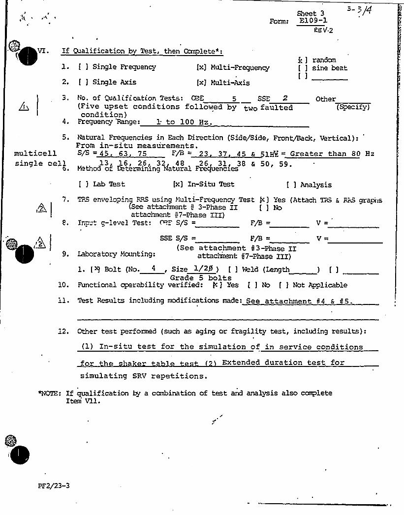
VI. Ifl. f ) Single Frequency fx] Multi-Frequency
[x] Multi-Axis2. f ) Single Axis
Qualification b Test, then Ccxnolete":Q ] randemf ] sine beatf )
0 ~
4,
No. of ~alification Tests: CBE 5 SSE 2(Five upset conditions followed by two faultedcondition)
Frequency 'Range: 1 to 100 Hz.
Other(Specify)
multice 1 1
single eel/0 ~
Natural Frequencies in Each Direction (Side/Side, Front/Back, Vertical):From in-situ measurements.S/S = 45 63 75 F/B = 23 37 45 6 51' Greater than 80 Hz
13'6I 26I, 32 48 26'1 g 38 Q 50~ 59.M thcd o~ Determining natural Frequencies
f j Lab West fx] In-Situ 'Inst [ ] Analysis
TRS envelopin" RPS using Multi-Frequency Test g] Yes {Attach TRS a Bic5 graphs|See attachment 5 3-Phase XI [ ) Ncattachnmt 47-Phase XIX)
Inpu. c-level Test: P.F S/S = F/B = V =
SSE S/S = F/B =
{See attachment N3-Phase IILaboratory Mounting: attachment I7-Phase XIX)
V-
10.
fx) Bolt (No. 4, Size 1/2g ) f ] Wld (Length ) f )Grade 5 bolts
Functicnal cperability verified: g ) Yes f ) No f ) Not Applicable
Results including modifications made: See attachment 44 & ~5.
12. Other test performed (such as aging or fragility test, including results):
(1) Xn-situ test for the simulation of in service conditions
for s Extended duration test forsimulating SRV repetitions.
~: Xf qualification by a ccmbination of test and analysis also ccapleteIteri Vll.
PF2/23-3

3-+fQSheet 4
Form: El+9- l
(Not Applicable)Vll . If Qualification b Anal is, then co lete:
1. Method of Analysis:
[ ] Static Analysis f ) Equivalent Static Analysis
[ ] Dynamic Analysis [ ] Time-History [ ] Response pectrum
[) 2D
[ ] Finite Element f ] Beam
6. Damping: OBE
StressAllowable
TotalStress
2. Natural Frequencies in Each Direction (Side/Side, Front/Back rVertical):
S/S = F/B = V =
3. Model type: f ] 3D [r] 1Dr'] Closed Form Solutionr4. [ ) Computer Codes:
Frequency Range and No. of mx3es consider
[ ] Hand Calculations
5. Method of Combining Dynamic Responses: f ) Absolute Sum [ ) SRSS
[ ] Other:(Specify)
SSE Basis for the damping used:
7. Support Considerationns in the nndel:
8. Critical Structural Elements:
governing Loador Response Seismic
A. Identification Location Combination Stress
rB. rMax. CriticalD flection L.xation
Maximum Allowable Deflectionto Assure Functional
rabilit
pF2/23-4

ATTACHMENT 4

~ )4 ~
f-I/1
SUSQrJZ&%% ST&v, 2 - TRIC STATION
K'ITS 1 A%0 2
DYMC QUALIFICATIONO."K}'JIM')R
WAIT 1 & CQeDN
125 V dc Distribution Panels
B&.7L F0R~ME ORDER NO.: 8856-E-120
SQRT FOiM NLNBER(S ): E120-1
'Ihe Qualification Report(s) identified above have been evaluated byBe&tel and the cmcnnent identified above has been repxalifed, Wereneo ssary, to shm that the cmmnent is capable of meeting therecuirmoats of the Susquohanna Ecyipmt Qualification Program for,Dynamic Eaads and the NRZ Seismic Qualification Review Team (S~) Program.
'WP27/34-1

~ p g s
'

Sheet 1Form:
Qualification Sana of i nt
I. Plant Name: SUSQU:-WANA
l. Utility: PP&L
2. NSSS: GE 3. A/E: BECHTEL
TKEe:
II. Canaonent Name: 125 V dc Distribution Panels E120
1, Sccpe: [ ] NSSS [ ~ ] BOP
CDP-222 jt=~~ >- ~ F-C-'-P0 4 Quantity:
3. &ndor- H"WJR4. If the c<xaonent is a cabinet or panel, name and mcdel hb. of the devices
includec:
R. V.P. 8856-E-120-2 (Attachm nt ~l
5. physical Description a. Appearance Pan 1N x D x H
b. Dim nsions 20" x 10" x 90"
c. Weigh- 550 Ms
6. Lccation;: Building: Control Structure
Elevation: Elev. 771'
] Weld (Length )]
8. a. Systen in &~ich located: Electrical Power Distribution
b. Functional Description: 125 dc distribution panel
) BoltsWallMounted
c. Is the equipment required for [ ] Hot Standby [ ] Cold Shutdown[x] Both [ ] Neither
9. Pertinent Reference Design Specifications: 8856-E120
PF2/23-1
*Tag Nos.lD614lD6241D6341D644
2D6142D6242D6342D644

I 1~
p g ~
I I4
II~ l
Sheet 2Form: =120 1
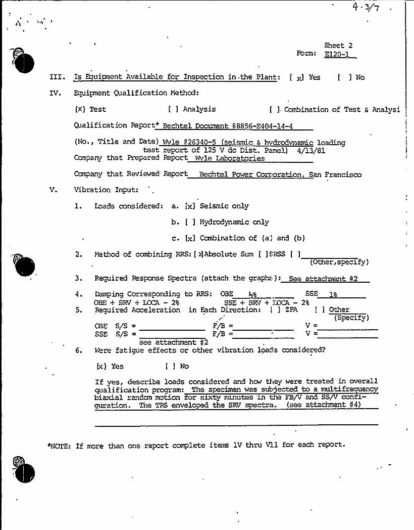
III. Is Ecruianent Available for Ins tion in the Plant: [ x] Yes [ ] No
IV. Equipnont CUalification Yathod:
[X] Test [ ] Analysis [ ] Ccebination of Test 6 Analysi
V.
alification Report* Bechtel Document 48856-E404-14-4
(No., Title and Date) le 426340-5 seismic 6 h drod amic loadingtest report of 125 V dc Dist. Panel) 4/13/81
Ccrnpany that Prepared Report le Laboratories
Car@any that Reviewed Report Bechtel Pawer Cortxoration San Francisco
Vibration Input:
1. Loads considered: a. fx] Seismic only
b. [ ] Hydrodynamic cnly
c. fx] Canbination of (a,'nd (b)
2. H thod of ccmbining RRS: [/Absolute Sum [ ]SRSS [ ](Other, specify)
3. Required Response Spectra (attach the graphs): Se attachment "2
4,
5.
6.
Damping Correaron3ing to RSS: OSS SSE
OBE + SRV + LOCA — 2% sss + sRv + Mcn - 2aRequired Ao"eleration in Each Direction: I ] ZPA [ ] Other
(Specify)CBE S/S = F/B = V =
SSE S/S = F/B = V =
see attac?mnt 42Vhre fatigue effects or other vibration loads consia red?
[x] Yes []NoIf yes, describe loads considered and hm they were treated in overallqualification program: Tne specimen was subjected to a multi rectumbiaxial andan motion or sixty minutes in tM FB/V and SS/V confi-guration. The TRS enveloped the SRV spectra. (see attache 14)
NOZE: If more than one report ccaplete items 1V thru Vll for each report.

1a p ~ a
I l,
0
0

Sheet 3Form: E120-1
VI. If Qualification b Test, then Canolete*:
l. [ ] Single Frequency fx] Multi-Frequency[x) random[ ) sine beat[)
2. [ ] Single Axis fx) Multi-Axis
3. No. of Qualification Tests: CBE(Six faulted conditions)
4. Frequency Range: 1 to 100 Hz
SSE 6 Other(Spa.'if y)
5. Natural Frecyencies in Each Direction (Side/Side, Front/Back, Vertical):
S/S 16 32 37 63 F/B 19 t 23 g 30 36 58
6. M thod of Determining Natural Frequencies
[x] Lab Test [ ] In-Situ Test
V = 19 32 50 75 90
f ] Analysis
7. TRS enveloping RRS using Multi-Frequency Test f ] Yes (Attach TRS & RRS graphsSee attachment r,3 [] No
8. Input g-level Test: OBE S/S =
SSE S/S =
See attadment >39. Laboratory Mounting:
V =
l. [Q Bolt (No. 6, Size3," dia) [ ) R ld (Length ) f ]1
10. Functional operability verified:.:[ x] Yes [ ) No [ ) Not Applicable
ll. Test Results including mx3ifications made: The sp cion was qua1ified~ without ccznpromise on structural and fun~on integrity.
12. Other test performed (such as aging or fragility test, including results):
Waded duration test for 60 minutes (see attachnent 04)
"NOIr.: If qualification by a canbination of test and analysis also carpleteItem Vll.

~ I*
~ + $ 1~
Form:Sheet 4
Vll . If Qualification b Anal is, then lete: (Not applicable)
l. Method of Analysis:
[ ) Static Analysis [ ] ~ivalent Static Analysis
[ ] adamic Analysis [ ] Time-History [ ) Response SpectrumI
2. Natural Frequencies in Each Direction (Side/Side, Fron /Back, Vertical):
S/S =
3. Hcdel type: [ ) 3D [) 2D
V
[) lD
[ ) Finite Element [ ) Beam
4. [ 1 Ccaputer Ccdes:
Frequency Range and No. of mx3es consider'ed:
[:! Hano Calculations
[ ) Closed Form Solution
6. D-mping: GBE SSE
7. S 'gport Considerationns in the model.:
8. D itical Structural Elements:
'.
N=-'Sod of Ccmbining Dynamic Respons'es: [ ] Absolute Sum [ ] SRSS
[ ] Other:/ (Specify)
Basis for the da~ing used:
Governing Loador Response
A. Iclantification Location CcrnbinationSeismic TotalStress Stress
StressAllowable
B. Ya.x. CriticalDeflection Location
Maximum Alliable Deflectionto Assure Functional
rabilit
PF2/23-4

jg ~ ~
0

WYLE LABORATORIESI
, CUSTOMER Job No .
f -&/qReoort No.26340-5Page No .
Pull Scale l c2 g Accel. No. Control ( Q Response ( )
erator
Date Z—Specimen 2.
Deopfog ~X C r CJ /45') E
Axis of TestSgu /~P4CZ re~>
'/57PFsr st'o sttsrstsFF)RES PONS E 5 PECTRU M
2 2 6 4 C 7 4 410 S 6 4 C 7 4 110 2 $ 6 4 C 2 4 450
Is 111 ~ SSIS ~
~ ~ I ~
~ t I I 1 ~ Its ~ I II ~
4
~ ~ ~ ~
II I ll
I I I I
1 ~ 1 SS ~ 11 ~
~ I I 1 ~ I S I I 1 I ~ tiI II'lsl I I I I IIII I lilt I I I I 4 Ilt
~ I
lilt I I II I I I
~ tsI I I '11I,'1 I I I
s
1 ~
I I I ~ ~ ~
I I 11 I I I Ililt Issti
~ ~ ~ 1 ~ IF 11 tttI ~ I I I I II Il IIII 10
'hl
I 0z0
1
W
VVC
~ I I ~ I ~
1
1 t 1
~ ~ I 'I ~ ~ ~ I I ~ ~ 1 ~ I ~ ~ I~ ~
~ I 1
Is ~ ~
I I tt ~, ~ I ~ I ~ ~ I
s
~ '1 ~
~ t I S I I ~ 1
~ ~
I 'I 1st
1 ~ s s ~ st ~
s
~ ~ 1 1 ~ 1 ~ '~ 1 ~ s ~ ~ ~ ~ ~ I ~ ~ ~
1111 ~ 111 111 I t . ~ ~ ~ I I 1 I ~ ~ I I ~ I st ~ s ~ ~ I ~ I I I I ~ I 11 I ~ ~ ~ s II ~ I I I I I 1st ~
1441/ ItslI 11 I ~ I
I I s I Ill tlsl I
I I II IIts I I
I 1 st I S I S Isl I~ I I I II 1st
it Illst ~;
Is)4ll s It Ills 50
~ ~ I ~ 11 It ~ ~ ts ~
\ st~ ~ ~ ~ ~ ~ ~ I .s ~ ~
1 1 I ~ 1 ~
~ 11 ~ I I ~ I I s ~
~ ~
~ I~ 1 1 ~ ~
~ I 1 I 1 '1 I ~
s I ~ ~ ~ ~ I ~ 1 I ~ ~C
I I ~ ~ I ~ ~ 1
~ 1 I ~
I ~ I 1 I ~ ~ 1 ~ I t I ~ I $ ~ 1 ~ ~ 11 11 1 1 ~ 1 ~ 1 ~
1stI ~ st t ~ ~ ' ~ I ~ 1 ~
~ I I III'II I I II
11 ~ I ~ . ~ I II ~ ~ I
~ I ~ ~
1 ( ~
I ' ~ .' ~ s
~ . I I ~ 11 ~
11 ~ I ~ '1~ I I I tttl
s ~ I ~
I I I I1 'I ~ I I
I ~ I I
~ 11 II ~ 11
FREQUENCY HZI I I I 1
2 10 100 200 1000

lp
~
l ~
0
g4
0

, ViY~E LABORATORIES(Qi ~ 4'gi I
" CUSTOMER Job No. 2. C~4 R
jl> C->/7Report. No.36340-6Page No.
/ nil Scale 1 c7 Accel. No. Control (c ) Response ( )
erator Specimen
Date Z.-S -F'I Damping ~ X
RESPONSE SPECTRUM
Axis of Test~/-P'gv/Sar~~ 7&x
~~~~+ Qe~/'Nv7E 7'/6 C C 7 7 10 2 2 i 4 C 7 C 010 C C 7 C ~ 1
10
~ t ~ t 't I ~
I I ~ I~ ~
I I ~
I ~
Is~ I ~ ~
~ I I t ~
~ ~ ~ ~
~ I ~ I ~ \ ~
I ~
~ ~ ~ I II ~ I I I I I II t ~ ~ I I I
~ I I I ~ It ~ I ~
I ~
~ I ~ ~ ~ II I I
7
~ ~ tI I ~ ~
~ ~ It ~ t I I t ~ ~
~ II I I ~ ~ ~
I I I ~
I It it ~ II I s 1st I I ~ I lit I ~ I I I I I I II~
I 1 sl IIII I II I I IIIIII I I I 1I ii i Il 4 I ~ i I
~ ~ II I 11 I
I I ~ Il II I 'll I
I ~
I ~
I ~ ~ ~ ~ ~ II III ~ III I
I e ll ill I I
I II I ~ ~ I I
Iiil Ii I I I I I 104 I I i I lil IIIIII1 4 3 I
I I ~ I I ~ st ~ I It I I ~ ~
~ t 'I
I I I ~ ~ ~
~ ~
~ I l
\t
, ~ I I ~ I It ~ II ~ I ~
~ I I
~ I
I I I 111 I It ~ \
I I I ~ I 1sl I t'ss sC
lie
ViePet
~ ~ II I I I ~ ~ ~
I I I I I IlI I I il'
~ t ~ t~ I IIII ' t
l i II I II~ III II till l 1 I
I ~
I ~
I I ~
~ ' IIII I'It ~ I I I I ~
I slitII I I li I
S I I li ltl I I itI ~ Is 1st I I 1
\ I~ ~ ~ ~ ~ I stt
I I I I I I I Itl slit I I
I I Ills il~ I I I I
t I t tI I ~ I
II lilt~ I I I I I 4 I
~ I
'! '0t \ I
I t I I I I ~ II ~
I I I ~ I 'st t ~, ~
1st ~ ~ I ~ ~
I st I''I I ~ 1st ~ ~
I It ~ II I ~ t I t t ~ I ~ I ~ ~
~ I ~
I ''I ~ I
~ ~ I ~
' II I
~ ~ ~ II I
I II ~ ~ I I
I I I ~ I I I I I I I ~ III ~ l 1 I ~ I ~ ~ I I ~ I II'I ~
Io FREQUENCY Hz
I
'I ~ I IIII I Ill ll ~ I I ~ I IIlls ll~ I ''
~ I I I ~ II I ~'
I I
~ I ~
I ~
I ~
~ ~
~ I I II I t ~ I I'I
I I 'I I ~ I 11 ~ ~ ~
I I II Is ~ I I I I III ills ~ I I ~
1

jQ" ~ I 'Q ~
(
ATTACHMENT 5

I
C'
t
f
J'

NEDO: 22l77CLASS: IIRTE: AUG 1982TIE: 82NED875PM% Soy of ~~+
FIGURE 39K7ZIQH DIRECTICHS
NOTE:!IWITCHBRACKET IS ROTATED90 DEG COUNTERCLOCKWISE SO IT IS VISIBLE
I
r"
MOTION DIRECTIONS

I.
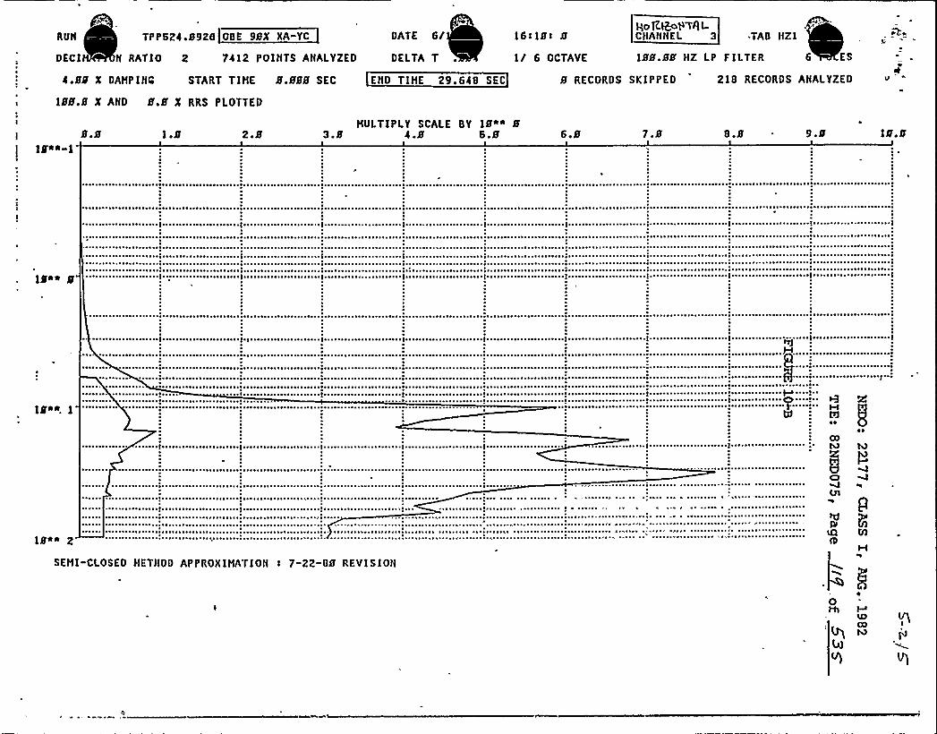
RUN TPPS24,8926 OBE 98X XA-YC DATE 6/ 16~18~ 8yoga>R I-CHANNEL 3 .TAB HZ I
4.88 X DAHPINC START TIHE 8.888 SEC END TIHE 29.64B SEC
188.8 X AND 8.8 X RRS PLOTTED
DECI N RATIO 2 7412 POINTS ANALYZED DELTA T I/ 6 OCTAVE 188.88 HZ LP FILTER 6 ES
8 RECORDS SKIPPED 21B RECORDS ANALYZED
I 8.818"~-I
1.8 2.8HULTIPLY SCALE BY 18~i 8
3.8 4.8 6.8 6.8 7.8 8.8 9.8
~ ~ ~
18*~ 8 ' ~ I ~ ~ ~
0~ I ~ ~ ' ~ 'I' ' ~ ~ ~ ~ I ~
IS~~ I~ ~ ~
~ ~ ~ ~ ~ ~ ~ ~ ~ ~ ~
~ ~
~ I
~ ~
~ ~ ~ ~ ~ ~ ~ ~
oUl
~0
18*~ 2
SEHI-CLOSED HETHOD APPROXIHATION t 7-22-08 REVISIONH

lgA
4h~
0
'
0

RUN 6 TPP624 8926 QBE 98Z XA"YC DATE 8 . ~82 Ibtl8> 8 !y~T(CALCHA'NNEL TAB V
TION RATIO
Z OAMPIMt$
2 7412 POINTS ANALYZED OKLTA 84 I/ 6 PCThVK
STAllT TIHE $ .$$$ EC EHC TIHE 2$ .6 ~ 6 EEC 8 RECORDS SKIPPED
188.88 HZ LP FILTER POLES
218 RECORDS ANALYZED ~ — .
If~~"I~ 3 .6
I88.8 Z AND 8.8 Z RRS PLOTTED ;~ccELEnaTroN (.G)HULTIPLY SCALK BY 18""
.9 1.2 I.b 1.8 2.1 2.4 2.7 3.8
0 ~ ~
a
18'+ I
l 1801 8l~
I Pl
>n~ ~I M ~
aN
~ ~ ~
0 ~
~ ~
~ ~
~ *
~ ~ a
I ~
a ~ a ~
~ (
'"(
~ ~ (
~ ~
'(
18*0 2
SEHI-CLOSED HETHOO APPROXIHATION ( 7-22"88 REVISION

'I
1"
0

TPP624o8926 HSIV SSEX 8%X 188
TION RATIO 2 7514 POINTS ANALYZED
4.88 X DAMP INC START TIME, 8.888 SEC
188.8 X AND 8.8 X RRS PLOTTED
DATEHORROR'TAL
BZ 9t58s 8 C ANNEL 3 TAB N
DELTA 884 I/ 6 OCTAVE 188.88 HZ LP FILTER
END TIHE 38.866'EC 8 RECORDS SKIPPED 221 RECORDS
IPOLES
ANALYZED
18~~-I8.8 0 3 .6 .9
MVLTIPLY SCALE BY I8"~ I1.2 1.5 1.8 2.1 2.4 2 7 3.8
I8~~ 8 I ~
IP~ I
~ ~
I8i* 2
SElil-CLOSED METHOD APPROXIHATION: 7-22"B8 REVISION
H ÃW
~t
I~o
pM
0

fr ~-g,
0

TPP524.8926 HSIV SSEX BZXA-188ZY DATEV 6'APICAL
2 9t585 S CHANNEL 4 TAB V
DE TION RATIO 2 7514 POINTS ANALYZED DELTA .SS4 I/ 6 OCTAVE 188 .88 ll2 LP FILTER
4.88 Z DAHP INC START TIHE S.S88 SEC END TIHE 38.8S6 SEC 8 RECORDS SKIPPED 221 RECORDS
188.8 X AND 8.8 X RRS PLOTTED
I
POLES
ANALYZED
18~"-I1.8
HVLTIPLY SCALE BY 18~* I1.5 2.8 2.5 3.S 3.S 4.8 4.5 S.B
1$"* 8 "I~ i ~
~ ~
~ ~ ~ ~
~ ~ ~ ~ ~ ~ ~ ~ ~
~ ~ ~
IS** 2
~ ~
~ 0
hl bJ
ppV
SEHI-CI.OSED HETHOD API'IIOXIHATION ! 7"22-88 IIEVIS IONQ M
0

~ ~