forward area refueling equipment (fare) (american air
TRANSCRIPT
*TM 10-4930-229-12&P
TECHNICAL MANUAL
OPERATOR AND UNIT MAINTENANCE MANUAL(INCLUDING REPAIR PARTS AND SPECIAL TOOLS LIST)
FOR
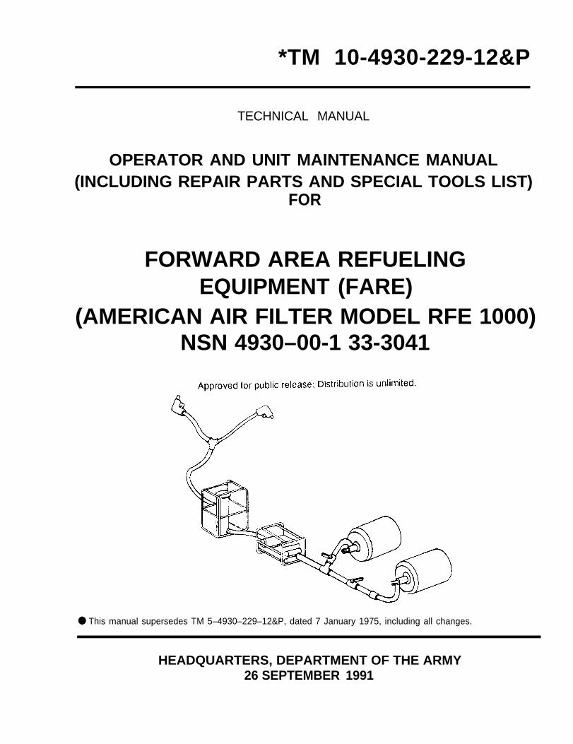
FORWARD AREA REFUELINGEQUIPMENT (FARE)
(AMERICAN AIR FILTER MODEL RFE 1000)NSN 4930–00-1 33-3041
● This manual supersedes TM 5–4930–229–12&P, dated 7 January 1975, including all changes.
HEADQUARTERS, DEPARTMENT OF THE ARMY26 SEPTEMBER 1991

CHANGE
NO. 4
TM 10-4930-229-12&PC 4
HEADQUARTERSDEPARTMENT OF THE ARMY
WASHINGTON, D.C., 5 January 1996
Operator and Unit Maintenance Manual(Including Repair Parts And Special Tools List)
For
FORWARD AREA REFUELING EQUIPMENT (FARE)(AMERICAN AIR FILTER MODEL RFE 1000)
NSN 4930-00-133-3041
DISTRIBUTION STATEMENT A: Approved for public release; distribution is unlimited.
TM 10-4930-229-12&P, 26 September 1991, is changed as follows:
1. Remove and insert pages as indicated below. New or changed text material is indicated by a vertical barin the margin. An illustration change is indicated by a miniature pointing hand.
Remove pages Insert pages
C-1 and C-2 C-1 and C-2
F-19 and F-20 F-19 and F-20
2. Retain this sheet in front of manual for reference purposes.
TM 10-4930-229-12&PC 4
By Order of the Secretary of the Army:
Official:
YVONNE M. HARRISONAdministrative Assistant to the
Secretary of the Army01025
DISTRIBUTION:
DENNIS J. REIMERGeneral, United States Army
Chief of Staff
To be distributed in accordance with DA Form 12-25-E, block no. 3573, requirements forTM 10-4930-229-12&P.
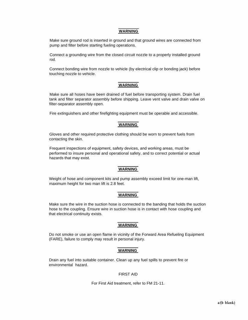
WARNING
Make sure ground rod is inserted in ground and that ground wires are connected frompump and filter before starting fueling operations.
Connect a grounding wire from the closed circuit nozzle to a properly installed groundrod.
Connect bonding wire from nozzle to vehicle (by electrical clip or bonding jack) beforetouching nozzle to vehicle.
WARNING
Make sure all hoses have been drained of fuel before transporting system. Drain fueltank and filter separator assembly before shipping. Leave vent valve and drain valve onfilter-separator assembly open.
Fire extinguishers and other firefighting equipment must be operable and accessible.
WARNING
Gloves and other required protective clothing should be worn to prevent fuels fromcontacting the skin.
Frequent inspections of equipment, safety devices, and working areas, must beperformed to insure personal and operational safety, and to correct potential or actualhazards that may exist.
WARNING
Weight of hose and component kits and pump assembly exceed limit for one-man lift,maximum height for two man lift is 2.8 feet.
WARNING
Make sure the wire in the suction hose is connected to the banding that holds the suctionhose to the coupling. Ensure wire in suction hose is in contact with hose coupling andthat electrical continuity exists.
WARNING
Do not smoke or use an open flame in vicinity of the Forward Area Refueling Equipment(FARE), failure to comply may result in personal injury.
WARNING
Drain any fuel into suitable container. Clean up any fuel spills to prevent fire orenvironmental hazard.
FIRST AID
For First Aid treatment, refer to FM 21-11.
a/(b blank)


TM 10-4930-229-12&PC 3
CHANGE
NO. 3
HEADQUARTERSDEPARTMENT OF THE ARMY
WASHINGTON, D.C., 1 February 1994
Operator and Unit Maintenance Manual(Including Repair Parts and Special Tools List)
f o r
FORWARD AREA REFUELING EQUIPMENT (FARE)(AMERICAN AIR FILTER MODEL RFE 1000,
NSN 4930-00-133-3041)
DISTRIBUTION STATEMENT A: Approved for public release; d is tr ibut ion i s unl imited .
TM 10-4930-229-12&P, dated 26 September 1991, is changed as follows:
1. Remove and insert pages as indicated below. New or changed text material isindicated by a vertical bar in the margin. An illustration change is indicatedby a miniature pointing hand.
Remove pages Insert pages
i and i i i and i i2-11 and 2-12 2-11 and 2-12---------------- ----- - 2 -12 .1 / (2 -12 .2 b lank)C-1 through C-4 C-1 through C-4D-1/(D-2 blank) D-1/(D-2 blank)
2. Retain this sheet in front of manual for reference purposes.
By Order of the Secretary of the Army:
Official:
GORDON R.SULLIVANGeneral,United States Army
Chief of Staff
MILTON H. HAMILTONAdministrative Assistant to the
Secretary of the Army06355
DISTRIBUTION:To be distributed in accordance with DA Form 12-25-E, block no. 3573, require-
ments for TM 10-4930-229-12&P.


TM 10-4930-229-12&PC 2
CHANGE
NO. 2
HEADQUARTERSDEPARTMENT OF THE ARMY
WASHINGTON, D. C., 15 January 1993
OPERATOR’S, UNIT, AND DIRECT SUPPORTMAINTENANCE MANUAL AND
REPAIR PARTS AND SPECIAL TOOLS LIST
TANK AND PUMP UNIT, LIQUID DISPENSING,FOR TRUCK MOUNTING
MIL DESIGN TANK AND PUMP UNITELECTRIC MOTOR DRIVENMODEL (97403) 13226E2150
NSN 4930-01-274-0021
Approved for public release; Distribution is unlimited
TM 10-4930-236-13&P, 30 August 1991 is changed as follows:
1. Remove and insert pages as indicated below. New or changed text material is indicated by a verticalbar in the margin. An illustration change is indicated by a miniature pointing hand.
Remove pages Insert pages
C–3 and C-4 C–3 and C-4
2. Retain this sheet in front of manual for reference purposes.
By Order of the Secretary of the Army:
MILTON H. HAMILTONAdministrative Assistant to the
Secretary of the Army02444
GORDON R. SULLIVANGeneral, United States Army
Chief of Staff
DISTRIBUTION:To be distributed in accordance with DA Form 12-25-E, block 5291,
Operator, Unit and Direct Support Maintenance requirements forTM 10-4930-236-13&P.


CHANGE
NO. 1
TM 10-4930-229-12&PC 1
HEADQUARTERSDEPARTMENT OF THE ARMYWASHINGTON, D. C., 3 JUNE 1992
Operator and Unit Maintenance Manual(Including Repair Parts and Special Tools List)
for
FORWARD AREA REFUELING EQUIPMENT (FARE)(AMERICAN AIR FILTER MODEL RFE 1000,
NSN 4930-00-133-3041)
Approved for public release; distribution is unlimited
TM 10-4930-229-12&P, 26 September 1991, is changed as follows:
1.
2.
Remove and insert pages as indicated below. New or changed text material is indicated bya vertical bar in the margin. An illustration change is indicated by a miniature pointing hand.
Remove pages Insert pages
i and ii i and iiF–1 and F–2 F-1 and F-2F–7 through F–12 F-7 through F-12F–17 through F–22 F-17 through F–22F–25 and F–26 F–25 and F–26
Retain this sheet in front of manual for reference purposes.
By Order of the Secretary of the Army:
Official:
GORDON R. SULLIVANGeneral, United States Army
Chief of Staff
MILTON H. HAMILTONAdministrative Assistant to the
Secretary of the Army01601
DISTRIBUTION:To be distributed in accordance with DA Form 12–25E, qty rqr block no. 0820.

TECHNICAL MANUAL
No. 10-4930-229-12&P
*TM 10-4930-229-12&P
HEADQUARTERSDEPARTMENT OF THE ARMY
WASHINGTON, D. C., 26 SEPTEMBER 1991
Operator and Unit Maintenance Manual(including Repair Parts and Speclal Tools Lists)
forFORWARD AREA REFUELING EQUIPMENT (FARE)
(MODEL RFE 1000, NSN 4930-00-133-3041)Current as of date is 28 June 1991
REPORTING ERRORS AND RECOMMENDING IMPROVEMENTS
You can help improve this manual. If you find any mistakes or if you know of a way toimprove the procedures, please let us know. Mail your letter, DA Form 2028(Recommended Changes to Publications and Blank Forms), or DA Form 2028-2 locatedin back of this manual direct to: Commander, US Army Aviation and Troop Command,ATTN: AMSAT–I–MP, 4300 Goodfellow Blvd., St. Louis, MO 631 20–1 798. A reply will befurnished to you.
Distribution STATEMENT A: Approved for public release; distribution is unlimited
CHAPTER 1
Section ISection IISection III
CHAPTER 2
Section ISection IISection IIISection IV
CHAPTER 3
Section ISection IISection III
TABLE OF CONTENTS
Page
INTRODUCTION . . . . . . . . . . . . . . . . . . . . . . . . . . . . . . . . . . . . . . . . . . . . . . . . . . . . . . 1-1OVERVIEW . . . . . . . . . . . . . . . . . . . . . . . . . . . . . . . . . . . . . . . . . . . . . . . . . . . . . . . . . . 1-1General Information . . . . . . . . . . . . . . . . . . . . . . . . . . . . . . . . . . . . . . . . . . . . . . . . . . . . 1-1Equipment Description and Data..... . . . . . . . . . . . . . . . . . . . . . . . . . . . . . . . . . . . . . 1-3Principles of Operation . . . . . . . . . . . . . . . . . . . . . . . . . . . . . . . . . . . . . . . . . . . . . . . . . 1-14
OPERATING INSTRUCTIONS . . . . . . . . . . . . . . . . . . . . . . . . . . . . . . . . . . . . . . . . . . . 2-1OVERVIEW . . . . . . . . . . . . . . . . . . . . . . . . . . . . . . . . . . . . . . . . . . . . . . . . . . . . . . . . . . 2-1Description and Use of Operator Controls and lndicators . . . . . . . . . . . . . . . . . . . . . . . 2-1Preventive Maintenance Checks and Services (PMCS) . . . . . . . . . . . . . . . . . . . . . . . . 2-5Operation Under Usual Conditions.. . . . . . . . . . . . . . . . . . . . . . . . . . . . . . . . . . . . . . 2-9Operation Under Unusual Conditions. . . . . . . . . . . . . . . . . . . . . . . . . . . . . . . . . . . . . . 2-15
OPERATOR MAINTENANCE INSTRUCTIONS . . . . . . . . . . . . . . . . . . . . . . . . . . . . . . 3-1OVERVIEW . . . . . . . . . . . . . . . . . . . . . . . . . . . . . . . . . . . . . . . . . . . . . . . . . . . . . . . . . . 3-1Lubrication Instructions . . . . . . . . . . . . . . . . . . . . . . . . . . . . . . . . . . . . . . . . . . . .. 3-1Operator Troubleshooting . . . . . . . . . . . . . . . . . . . . . . . . . . . . . . . . . . . . . . . . . . . . ...3-1Operator Maintenance . . . . . . . . . . . . . . . . . . . . . . . . . . . . . . . . . . . . . . . . . . . . . . . ...3-4
* This manual supersedes TM 5-4930-229-12&P, dated 7 January 1975, including all changes.
i

TM 10-4930-229-12&P
TABLE OF CONTENTS (cont)
CHAPTER 4
Section I
Section IISection IIISection IVSection VSection VI
APPENDIX A
APPENDIX B
APPENDIX C
APPENDIX D
APPENDIX E
APPENDIX FSection ISection IIGroup 01
UNIT MAINTENANCE INSTRUCTIONS. . . . . . . . . . . . . . . . . . . . . . . . . . . . .
Page
4-1OVAERVIEW . . . . . . . . . . . . . . . . . . . . . . . . . . . . . . . . . . . . . . . . . . . . . . . . . ..4-1Repair Parts, Special Tools, Test, Measurement and DiagnosticEquipment (TMDE) and Support Equipment . . . . . . . . . . . . . . . . . . . . . 4-1
Service Upon Receipt . . . . . . . . . . . . . . . . . . . . . . . . . . . . . . . . . . 4-1
Unit Preventive Maintenance Checks and Services (PMCS) . . . . . . . . . . . . . 4-2Unit Troubleshooting . . . . . . . . . . . . . . . . . . . . . . . . . . . . . . . . . . . . . . . . . ...4-3Unit Maintenance Procedures . . . . . . . . . . . . . . . . . . . . . . . . . . . . . . . . . . ...4-6Preparation for Shipment or Storage . . . . . . . . . . . . . . . . . . . . . . . . . . . . . ...4-35
REFERENCES . . . . . . . . . . . . . . . . . . . . . . . . . . . . . . . . . . . . . . . . . . . . . . ..A-1
MAINTENANCE ALLOCATION CHART . . . . . . . . . . . . . . . . . . . . . . . . . . . . . B-1
COMPONENTS OF END ITEM AND BASIC ISSUE ITEMS LISTS . . . . . . . . C-1
ADDITIONAL AUTHORIZATION LIST . . . . . . . . . . . . . . . . . . . . . . . . . . . . . D-1
EXPENDABLE/DURABLE SUPPLIES AND MATERIALS LIST . . . . . . . . . . . E-1
REPAIR PARTS AND SPECIAL TOOLS LIST . . . . . . . . . . . . . . . . . . . . . . . . F-1Introduction, . . . . . . . . . . . . . . . . . . . . . . . . . . . . . . . . . . . . . . . . . . . . . . . ..F-1Parts Lists . . . . . . . . . . . . . . . . . . . . . . . . . . . . . . . . . . . . . . . . . . . . . . . . . ..F-1Suction Hose Kit . . . . . . . . . . . . . . . . . . . . . . . . . . . . . . . . . . . . . . . . . . . . ..F-8Hose and Component Kit..... . . . . . . . . . . . . . . . . . . . . . . . . . . . . . . . . ..F–10Butterfly Valve Assembly . . . . . . . . . . . . . . . . . . . . . . . . . . . . ..F-12Tee Assembly . . . . . . . . . . . . . . . . . . . . . . . . . . . . . . . . . . . . . . . . . . . . . . ..F–14Elbow Coupler Valve . . . . . . . . . . . . . . . . . . . . . . . . . . . . . . . . . . . . . . . . ..F-16Adapter Assembly, 3 In. x 2 In. and Adapter Assembly, Male x Male . . . . . F–18Adapter Assembly, 4 In. x 2 In... . . . . . . . . . . . . . . . . . . . . . . . . . . . . . . . ..F–20Closed-Circuit Refueling Nozzle and Gravity-Feed Adapter . . . . . . . . . . . . . F–22Wye Fitting Assembly . . . . . . . . . . . . . . . . . . . . . . . . . . . . . . . . . . . . . . . . ..F–24Water Detector Kit Adapter . . . . . . . . . . . . . . . . . . . . . . . . . . . . . . . . . . . . ..F–26Frame Assembly . . . . . . . . . . . . . . . . . . . . . . . . . . . . . . . . . . . . . . . . . . . . ..F–28Pump/EngineAssembly . . . . . . . . . . . . . . . . . . . . . . . . . . . . . . . . . . . . . . ..F-30Filter-Separator Assembly . . . . . . . . . . . . . . . . . . . . . . . . . . . . . . . . . . . . ..F–32
Illust/Figure
F-1F-2F-3F-4F-5F-6F-7F-8F-9F-10F-11F-12F-13
Index Index 1
i i
TM 10-4930-229-12&P
LIST OF ILLUSTRATIONS
FigureNumber Title Page
1-11-21-31-41-51-61-72-12-22-32-42-54-14-24-34-44-54-64-74-84-94-104-114-124-134-144-15
Typical Layout of FARE . . . . . . . . . . . . . . . . . . . . . . . . . . . . . . . . . . . . . . . . . . . . . . . . . . 1-2Pump/Engine Assembly . . . . . . . . . . . . . . . . . . . . . . . . . . . . . . . . . . . . . . . . . . . . . . . . . . . . . . 1-4Filter/Separator Assembly . . . . . . . . . . . . . . . . . . . . . . . . . . . . . . . . . . . . . . . . . . . . . ... 1-7Discharge Hoses, Fittings and Frame Assembly . . . . . . . . . . . . . . . . . . . . . . . . . . . . . . . . . . . 1-9Suction Hose Kit . . . . . . . . . . . . . . . . . . . . . . . . . . . . . . . . ... 1-12Collapsible Drum . . . . . . . . . . . . . . . . . . . . . . . . . . . . . . . . . . . . . 1-13Flow Diagram . . . . . . . . . . . . . . . . . . . . . . . . . . . . . . . . . . . . . . . . . . . . . . .1-15Elbow Coupler Valve Control . . . . . . . . . . . . . . . . . . . . . . . . . . . . . . . . . . . . . . . . . . . . . . . ...2-1Butterfly Valve Control . . . . . . . . . . . . . . . . . . . . . . . . . . . . . . . . . . . . . . . . . . . . . 2-2Filter/Separator Controls and lndicators . . . . . . . . . . . . . . . . . . . . . . . . . . . . . . . ... 2-3Two-Point Refueling Operation. . . . . . . . . . . . . . . . . . . . . . . . . . . . . . . . . . . . . . . . . . . . . . ...2-10FARE Piping Diagram for Filling Operation . . . . . . . . . . . . . . . . . . . . . . . . . . . . . . . . . . . . . . . . 2-13installing Band on Hose Assembly . . . . . . . . . . . . . . . . . . . . . . . . . . . . . . . . . . . . . ... 4-9GroundRod,Removal/installation . . . . . . . . . . . . . . . . . . . . . . . . . . . . . . . . . . . . . . . . . . . ...4-13Butterfly Valve, Disassembly/Assembly . . . . . . . . . . . . . . . . . . . . . . . . . . . . . . . . . . . . . . . ...4-15Butterfiy Valve,Removal/installation . . . . . . . . . . . . . . . . . . . . . . . . . . . . . . . . . . . . . . . . . ...4-17Elbow Coupler Valve, Disassembly/Assembly . . . . . . . . . . . . . . . . . . . . . . . . . . . . . . . . . . . . . 4-19Elbow Coupler Valve, Removal/lnstallation . . . . . . . . . . . . . . . . . . . . . . . . . . . . . . . . . . . . ...4-20Tee Fitting, Disassembly/Assembly . . . . . . . . . . . . . . . . . . . . . . . . . . . . . . . . . . . . . . . . . . ...4-22Adapter Assembly, Disassembly/Assembly . . . . . . . . . . . . . . . . . . . . . . . . . . . . . . . . . . . . ...4-24Adapter Assembly, Removal/lnstallation . . . . . . . . . . . . . . . . . . . . . . . . . . . . . . . . . . . . . . . ...4-24Adapter Nozzle, Removal/lnstallation . . . . . . . . . . . . . . . . . . . . . . . . . . . . . . . . . . . . . . . . . ...4-26Wye Fitting Assembly, Disassembly/Assembly . . . . . . . . . . . . . . . . . . . . . . . . . . . . . . . . . . . . . 4-28Wye Fitting Assembly, Removal/lnstallation . . . . . . . . . . . . . . . . . . . . . . . . . . . . . . . . . . . . . . . 4-29Water Detector Kit Adapter, Disassembly/Assembly . . . . . . . . . . . . . . . . . . . . . . . . . . . . . . . . 4-31Water Detector Kit Adapter, Removal/installation . . . . . . . . . . . . . . . . . . . . . . . . . . . . . . . . . . . 4-32Frame Assembly, Removal/lnstallation . . . . . . . . . . . . . . . . . . . . . . . . . . . . . . . . . . . . . . . . . . . 4-34
LIST OF TABLES
TableNumber Title Page
2-1 Operator/Crew Preventive Maintenance Checks and Services (PMCS) . . . . . . . . . . . . . . . . . . 2-83-1 Operator Troubleshooting . . . . . . . . . . . . . . . . . . . . . . . . . . . . . . . . . . . . . . . . . . . . . . . . . . . . . 3-24-1 Unit Preventive Maintenance Checks and Services (PMCS) . . . . . . . . . . . . . . . . . . . . . . . . . . 4-34-2 Unit Troubleshooting . . . . . . . . . . . . . . . . . . . . . . . . . . . . . . . . . . . . . . . . . ...4-4
iii/(iv blank)

TM 10-4930-229-12&P
CHAPTER 1
INTRODUCTION
Page
OVERVIEW . . . . . . . . . . . . . . . . . . . . . . . . . . . . . . . . . . . . . . . . . . . . . . . . . . . . . . . . . . . . . . . ...1-1Section I. General Information . . . . . . . . . . . . . . . . . . . . . . . . . . . . . . . . . . . . . . . . . . . . . . . ...1-1Section II. Equipment Description and Data. . . . . . . . . . . . . . . . . . . . . . . . . . . . . . . . . . . . . ...1-3Section III Principles of Operation . . . . . . . . . . . . . . . . . . . . . . . . . . . . . . . . . . . . . . . . . . . . . ...1-14
OVERVIEW
This chapter includes general information common to all Army equipment and specific information pertinent to theequipment covered in this manual.
Section I. GENERAL INFORMATION
Paragraph Page
1-1 Scope . . . . . . . . . . . . . . . . . . . . . . . . . . . . . . . . . . . . . . . . . . . . . . . . . . . . . . . . . . . . . . ...1-11-2 Maintenance Forms and Records . . . . . . . . . . . . . . . . . . . . . . . . . . . . . . . . . . . . . . . . ...1-11-3 Destruction of Army Materiel to Prevent Enemy Use . . . . . . . . . . . . . . . . . . . . . . . . . . . . . 1-11-4 Preparation for Storage or Shipment . . . . . . . . . . . . . . . . . . . . . . . . . . . . . . . . . . . . . . ...1-31-5 Reporting of Equipment improvement Recommendations (EIR) . . . . . . . . . . . . . . . . . . . . 1-3
1-1. Scope. The scope of this manual is described in the following subparagraphs.
a. Type of Manual. This manual provides operator and unit and maintenance instructions for Forward AreaRefueling Equipment (FARE) NSN 4930-00-133-3041. Included in these instructions are procedures forgettingup and operating the equipment under usual and unusual conditions as well as inspection, troubleshooting, repairand replacement of individual components and assemblies. This manual also provides a repair parts and specialtools list in Appendix F.
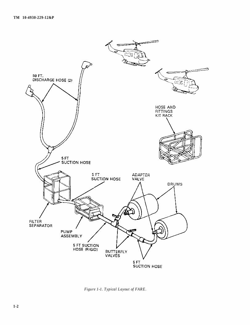
b. Equipment Name. Forward Area Refueling Equipment, hereinafter referred to as FARE (figure 1-1)
c. Purpose of Equipment . FARE is used to transfer fuel from 500 gallon (1892.5 liter) collapsible drums tohelicopters in forward combat areas. It can also be used to refuel fixed-wing aircraft and ground vehicles.
1-2. Maintenance Forms and Records. Department of the Army forms and procedures used forequipment maintenance will be those prescribed by DA PAM 738-750, The Army Maintenance ManagementSystem.
1-3. Destruction of Army Materiel to Prevent Enemy Use. For information and instructions ondestruction of Army materiel to prevent enemy use, refer to TM 750-244-3, Procedures for Destruction ofEquipment to Prevent Enemy Use.
1-1
TM 10-4930-229-12&P
Figure 1-1. Typical Layout of FARE.
1-2
TM 10-4930-229-12&P
1-4. Preparation for Storage or Shipment. TO prepare FARE for storage or shipment, refer to Chapter4, Section VI of this manual.
1-5. Reporting of Equipment Improvement Recommendations (EIR). If the design of FAREneeds improvement, let us know. Send us an EIR. You, the user, are the only one who can tell us what you don’tlike about your equipment. Let us know why you don’t like the design or performance. Put it on an SF-368(Product Quality Deficiency Report). Mail it to us at: Commander, U.S. Army Troop Support Command, ATTN:AMSTR-QP, 4300 Goodfellow Boulevard, St. Louis, Missouri 63120-1798. We will send you a reply.
Section II. EQUIPMENT DESCRIPTION AND DATA
Paragraph Page
1-6 Equipment Characteristics, Capabilities and Features . . . . . . . . . . . . . . . . . . . . . . . . . . . 1-31-7 Location and Description of Major Components . . . . . . . . . . . . . . . . . . . . . . . . . . . . . . . . 1-31-8 Equipment Data . . . . . . . . . . . . . . . . . . . . . . . . . . . . . . . . . . . . . .. . . . . . . . . . . . . .. .........................1-111-9 Safety, Care and Handling . . . . . . . . . . . . . . . . . . . . . . . . . . . . . . . . . . . . . . . . . . . . . . ...1-13
1-6. Equipment Characteristics, Capabilities and Features. A summary of the characteristics,capabilities and features of the equipment is contained in the following subparagraphs.
a. Characteristic FARE (figure 1-1 ) consists of simple, lightweight refueling equipment that can betransported by fixed-wing and rotary wing utility and cargo aircraft. This equipment includes a pump/engineassembly (figure 1-2), a filter/separator assembly (figure 1-3), discharge hoses, fittings and frame assembly (figure1-4) a suction hose kit (figure 1-5) and a collapsible fabric fuel drum (figure 1-6). (The drum is procuredseparately.) Each assembly is contained within a tubular aluminum framework and can be handled by twopersons.
b. Capabilities and Features. FARE is versatile and has several fueling capabilities. The operator need onlyselect the recommended combination of assemblies, nozzles and fittings for each fueling configuration. Thecapabilities and features may be summarized as follows:
(1) Primarily, the equipment is used to transfer fuel from 500-gallon (1892.5 liter) collapsible drums tohelicopters in forward combat areas.
(2) Refueling fixed-wing aircraft and ground vehicles is a secondary function.
(3) The equipment is provided with two types of nozzles, a closed circuit nozzle and a gravity fill adapternozzle, that will permit the operator to service aircraft or ground vehicles having either a gravity-feed orclosed-circuit fuel system capability.
(4) A 4 in. x 2 in. (10.16 cm x 5.08 cm) adapter and a 3 in. x 2 in. (7.62 cm x 5.08 cm) adapter are includedto allow acceptance of fuel from other sources.
1-7. Location and Description of Major Components. The major components of FARE aredescribed in the following subparagraphs, Specifications and data for the components of FARE are provided inparagraph 1-8.
1-3

TM 10-4930-229-12&P
a. Pump/Engine Assembly. (See figure 1-2.)
(1) The pump/engine assembly is a 100-gallon/minute (378.5-liter/minute) centrifugal pump (1 ) (refer toTM 10-4320-256-14&P for pump details). The pump is driven by a 4-cycle, 2-cylinder, 3-horsepower gasolineengine (2).
(2) The inlet connection to the pump is a standard 2-inch (5.08 cm) female camlock fitting (3). The dischargeport is fitted with a 2-inch male camlock fitting (4). The inlet and outlet ports are provided with a dust plug (5) andcap (6), respectively.
(3) A priming port (7) is located on top of the pump housing and a drain plug (8) is located at the lowest pointof the housing.
Figure 1-2. Pump/Engine Assembly (Sheet 1 of 2).
1-4
TM 10-4930-229-12&P
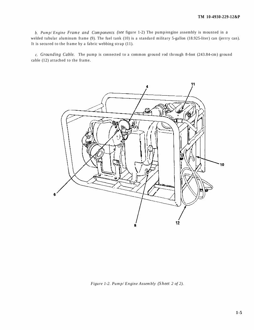
b. Pump/Engine Frame and Components (see figure 1-2) The pump/engine assembly is mounted in awelded tubular aluminum frame (9). The fuel tank (10) is a standard military 5-gallon (18.925-liter) can (jerrry can).It is secured to the frame by a fabric webbing strap (11).
c. Grounding Cable. The pump is connected to a common ground rod through 8-foot (243.84-cm) groundcable (12) attached to the frame.
Figure 1-2. Pump/Engine Assembly (Sheet 2 of 2).
1-5
TM 10-4930-229-12&P
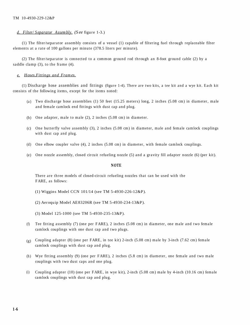
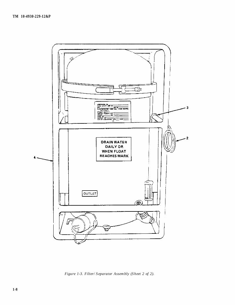
d. Filter/Separator Assembly. (See figure 1-3.)
(1) The filter/separator assembly consists of a vessel (1) capable of filtering fuel through replaceable filterelements at a rate of 100 gallons per minute (378.5 liters per minute).
(2) The filter/separator is connected to a common ground rod through an 8-foot ground cable (2) by asaddle clamp (3), to the frame (4).
e. Hoses.Fittings and Frames.
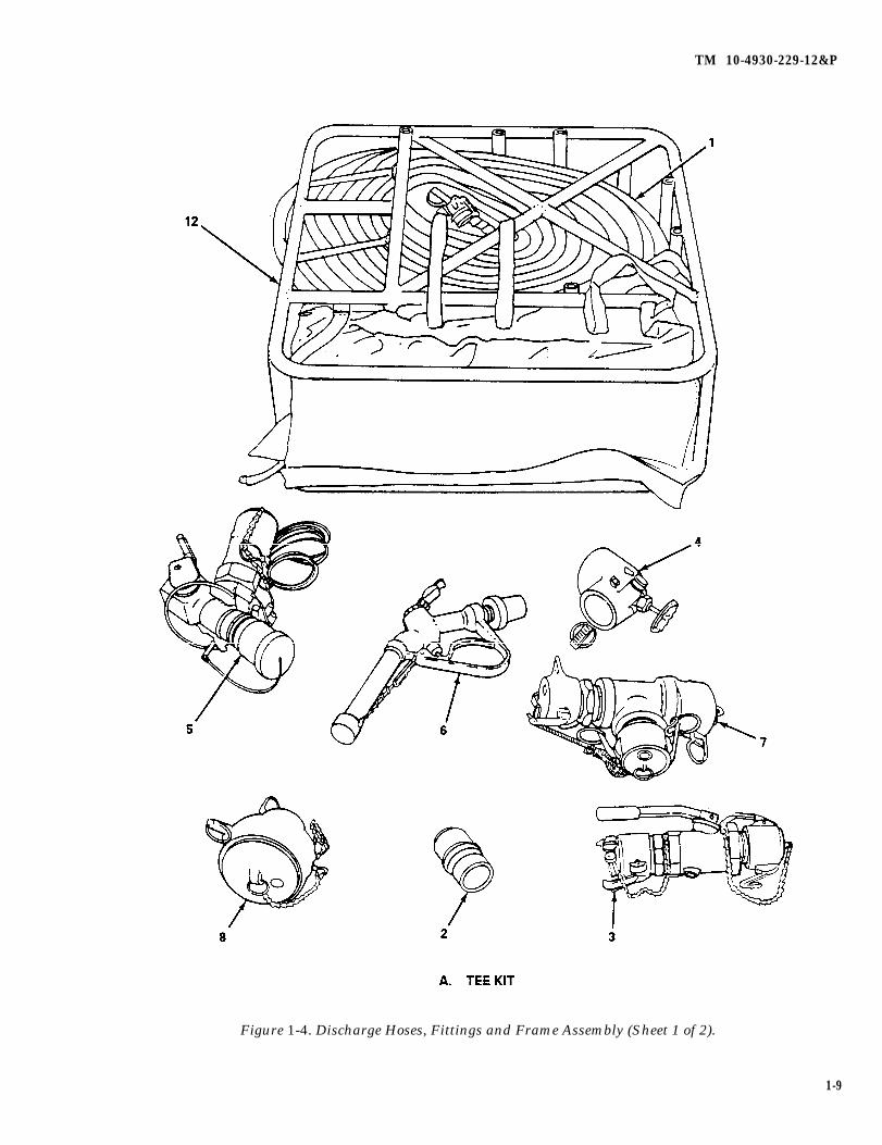
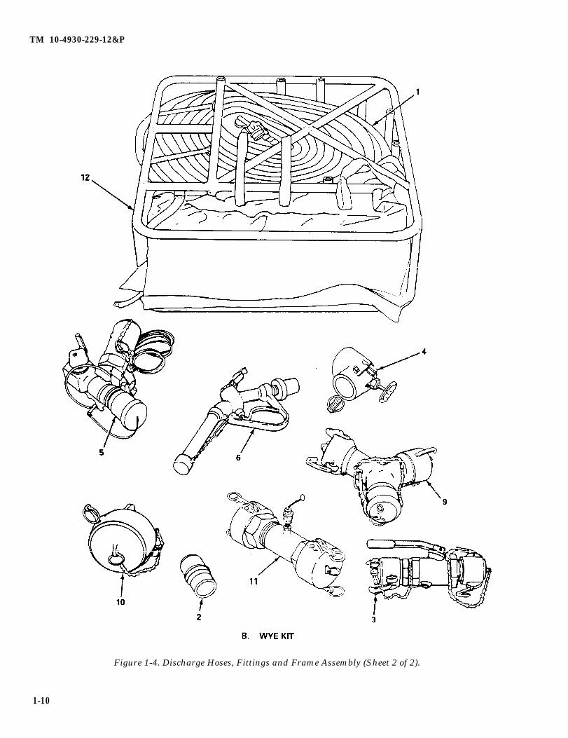
(1) Discharge hose assemblies and fittings (figure 1-4). There are two kits, a tee kit and a wye kit. Each kitconsists of the following items, except for the items noted:
(a)
(b)
(c)
(d)
(e)
(f)
(g)
(h)
(i)
1-6
Two discharge hose assemblies (1) 50 feet (15.25 meters) long, 2 inches (5.08 cm) in diameter, maleand female camlock end fittings with dust cap and plug.
One adapter, male to male (2), 2 inches (5.08 cm) in diameter.
One butterfly valve assembly (3), 2 inches (5.08 cm) in diameter, male and female camlock couplingswith dust cap and plug.
One elbow coupler valve (4), 2 inches (5.08 cm) in diameter, with female camlock couplings.
One nozzle assembly, closed circuit refueling nozzle (5) and a gravity fill adapter nozzle (6) (per kit).
NOTE
There are three models of closed-circuit refueling nozzles that can be used with theFARE, as follows:
(1) Wiggins Model CCN 101/14 (see TM 5-4930-226-12&P).
(2) Aeroquip Model AE83206R (see TM 5-4930-234-13&P).
(3) Model 125-1000 (see TM 5-4930-235-13&P).
Tee fitting assembly (7) (one per FARE), 2 inches (5.08 cm) in diameter, one male and two femalecamlock couplings with one dust cap and two plugs.
Coupling adapter (8) (one per FARE, in tee kit) 2-inch (5.08 cm) male by 3-inch (7.62 cm) femalecamlock couplings with dust cap and plug.
Wye fitting assembly (9) (one per FARE), 2 inches (5.8 cm) in diameter, one female and two malecouplings with two dust caps and one plug.
Coupling adapter (10) (one per FARE, in wye kit), 2-inch (5.08 cm) male by 4-inch (10.16 cm) femalecamlock couplings with dust cap and plug.
TM 10-4930-229-12&P
Figure 1-3. Filter/Separator Assembly (Sheet-1 of 2).
1-7
TM 10-4930-229-12&P
Figure 1-3. Filter/Separator Assembly (Sheet 2 of 2).
1-8
TM 10-4930-229-12&P
Figure 1-4. Discharge Hoses, Fittings and Frame Assembly (Sheet 1 of 2).
1-9
TM 10-4930-229-12&P
Figure 1-4. Discharge Hoses, Fittings and Frame Assembly (Sheet 2 of 2).
1-10
TM 10-4930-229-12&P
(j) Water detector kit adapter (11) (one per FARE in wye kit), male and female camlock couplings withdust cap and plug. It is required to attach fuel contamination test kit (NSN 6640-00-244-9478) atoutlet of filter/separator. The test kit is used to determine if the filter/separator is filtering properly.
(k) One component kit frame (12).
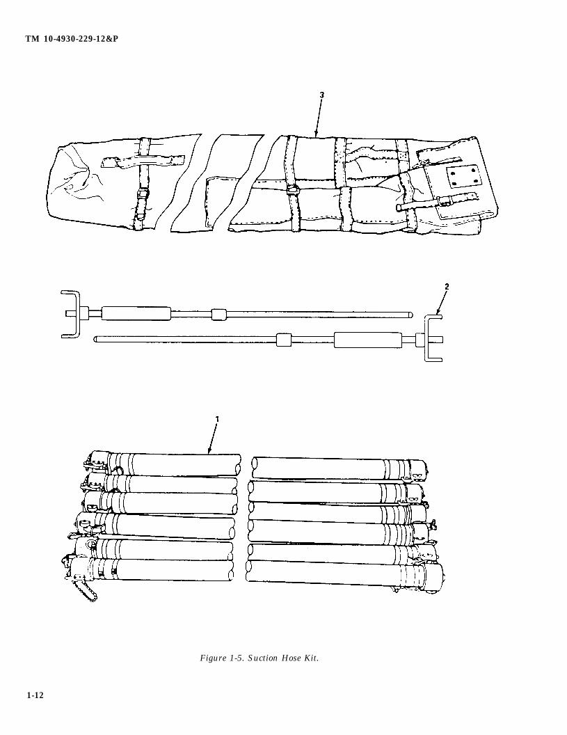
(2) Suction hose kit (figure 1-5). There are two kits, each consisting of the following items:
(a) Six suction hose assemblies (1), 5 feet (1.524 meters) in length, 2 inches (5.08 cm) in diameter, maleand female camlock couplings with dust cap and plug.
(b) Two ground rods (2).
(c) One suction hose container (3).
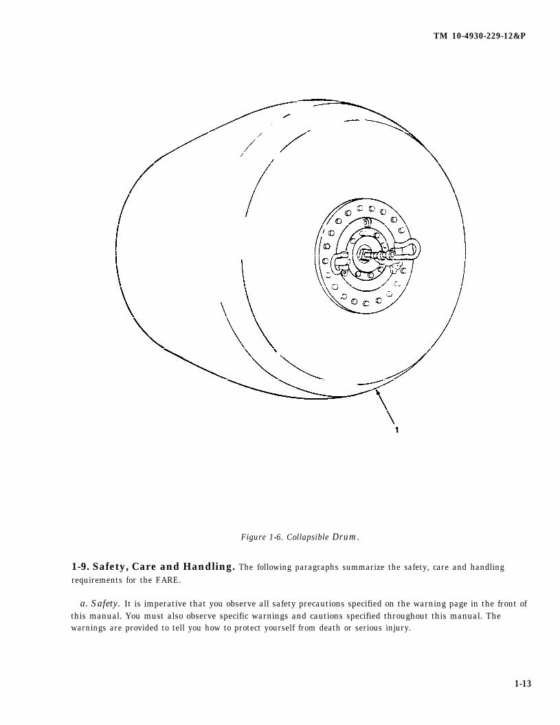
(3) Collapsible drum (figure 1-6). Refer to TM 10-8110-201-14&P for pertinent information on thecollapsible drum. The collapsible drum (1) is issued separately and is not part of the FARE.
1-8. Equipment Data.
Tabulated Data. The following summarizes the specific capabilities and limitations of the equipment and othercritical data needed by the operator and unit maintenance personnel for maintenance of the FARE components.
(1) Discharge hose and fitting kits.
Manufacturer . . . . . . . . . . . . . . . . . . . American Air Filter, Inc.Part No. . . . . . . . . . . . . . . . . . . . . . . ..13219E0503/13219E0504Shipping Dimensions
Length . . . . . . . . . . . . . . . . . . . ..39 in. (99 Cm)Width . . . . . . . . . . . . . . . . . . . . . . 11 in. (28 cm)Height . . . . . . . . . . . . . . . . . . . . ..30 in. (76cm)Weight . . . . . . . . . . . . . . . . . . . . . 172 pounds (78.1 kilograms)
(2) Suction hose kit.
Manufacturer . . . . . . . . . . . . . . . . . . . American Air Filter Corp.Part Number . . . . . . . . . . . . . . . . . ..13219E0501Weight . . . . . . . . . . . . . . . . . . . . . . . . 170 pounds (77.2 kilograms)
(3) Pump/engine assembly. Refer to TM 10-4320-256-14&P.
(4) Military standard engine. Refer to TM 9-2805-257-14.
(5) Filter/separator assembly. Refer to TM 5-4330-217-12&P.
(6) Closed circuit nozzle assemblies. Refer to TM 5-4930-226-12&P, TM 5-4930-234-13&P and TM5-4930-235-13&P.
(7) Collapsible drum. Refer to TM 10-8110-201-14&P.
1-11
TM 10-4930-229-12&P
Figure 1-5. Suction Hose Kit.
1-12
TM 10-4930-229-12&P
Figure 1-6. Collapsible Drum.
1-9. Safety, Care and Handling. The following paragraphs summarize the safety, care and handlingrequirements for the FARE.
a. Safety. It is imperative that you observe all safety precautions specified on the warning page in the front ofthis manual. You must also observe specific warnings and cautions specified throughout this manual. Thewarnings are provided to tell you how to protect yourself from death or serious injury.
1-13
TM 10-4930-229-12&P
b. Care and Handling. Observe the following precautions:
(1) Use care in handling components of the FARE as metal parts could cause personal injury.
(2) Use every effort to protect the FARE from the weather elements, dust, dirt, oil, grease, and acids.
Section III. PRINCIPLES OF OPERATION
Paragraph Page
1-10 General . . . . . . . . . . . . . . . . . . . . . . . . . . . . . . . . . . . . . . . . . . . . . . . . . . . . . . . . . . . . ...1-141-11 Principles of Operation . . . . . . . . . . . . . . . . . . . . . . . . . . . . . . . . . . . . . . . . . . . . . . . . ...1-14
1-10. General. For a formal refueling operation, the FARE is set up as shown in figure 1-7. Fuel from a500-gallon collapsible drum is fed through a series o fconnecting fittings suction hoses and a butterfly valve to apump. The fuel then flows through a filter/separator, which filters out any impurities in the fuel. The filter-separator also separates out any water that may have become mixed with the fuel through condensation orcontamination. The fuel then flows through a wye fitting to dispensing nozzles which are used to refuel aircraft.
1-11. Principles Of operation. (See figure 1-7.) For a two-point refueling operation:
a.
b.
c.
d.
e.
f.
9.
Fuel stored in a 500-gallon collapsible drum is directed through an elbow coupler valve (1) and amale-to-male adapter (2) into a 5-foot suction hose assembly (3).
The hose directs the flow to a butterfly valve (4) which operates as a shutoff valve and a fuel control valve.
When the valve is open, flow continues (through an additional 5-foot length of suction hose, if necessary) toa tee fitting (5) which enables two fuel supply legs to enter the refueling operation.
Flow is then directed through an additional 5-foot suction hose to the engine-driven centrifugal pumpassembly (6).
The fuel under pressure from the pump is directed through a 5-foot suction hose assembly (3) to thefilter/separator (8) where contaminants are filtered out and water, if present, is separated and collected.The engine/pump assembly and the filter/separator are connected by ground cables to a ground rod (7).
The output of the filter/separator is directed through the water detection adapter kit (9) and suction hose (3)to a wye fitting (10).
The wye fitting (10) directs the fuel flow to two refueling points through a 50-foot discharge hose assembly(11) and a closed-circuit nozzle (12). Each nozzle is connected through a ground cable to a ground rod. Inaddition, each nozzle is electrostatically bonded to the vehicle being fueled by a grounding clip or plug.
1-14

TM 10-4930-229-12&P
Figure 1-7. Flow Diagram.
1-15/(1-16 blank)

TM 10-4930-229-12&P
CHAPTER 2
OPERATING INSTRUCTIONS
Page
OVERVIEW . . . . . . . . . . . . . . . . . . . . . . . . . . . . . . . . . . . . . . . . . . . . . . . . . . . . . . . . . ...2-1Section I. Description and Use of Operator Controls and lndicators . . . . . . . . . . . . . . . . . . . . . . . . . 2-1Section II. Preventive Maintenance Checks and Services (PMCS) . . . . . . . . . . . . . . . . . . . . . . . . . . 2-5Section III Operation Under Usual Conditions . . . . . . . . . . . . . . . . . . . . . . . . . . . . . . . . . . . . . . . ...2-9Section IV. Operation Under Unusual Conditions . . . . . . . . . . . . . . . . . . . . . . . . . . . . . . . . . . . . . ...2-15
OVERVIEW
This chapter includes information on assembling and preparing the FARE to perform the specific mission for whichthe equipment is designed. This chapter also includes information on the controls and indicators, operatinginstructions, and preventive maintenance checks and services.
Section I. DESCRIPTION AND USE OF OPERATOR CONTROLS AND INDICATORS
Paragraph Page
2-1 Operator Controls and lndicators . . . . . . . . . . . . . . . . . . . . . . . . . . . . . . . . . . . . . . . . . ...2-12-2 Elbow Coupler Valve and Butterfly Valve Assembly Controls and Indicators . . . . . . . . . . 2-12-3 Filter/Separator Controls and lndicators . . . . . . . . . . . . . . . . . . . . . . . . . . . . . . . . . . . ...2-32-4 Pump/Engine and Closed Circuit Refueling Nozzle . . . . . . . . . . . . . . . . . . . . . . . . . . . . . . 2-5
2-1. Operator Controls and Indicators. Many of the controls and indicators used with the FARE arelocated on the individual assemblies that make up the FARE system. The controls are described in the followingparagraphs:
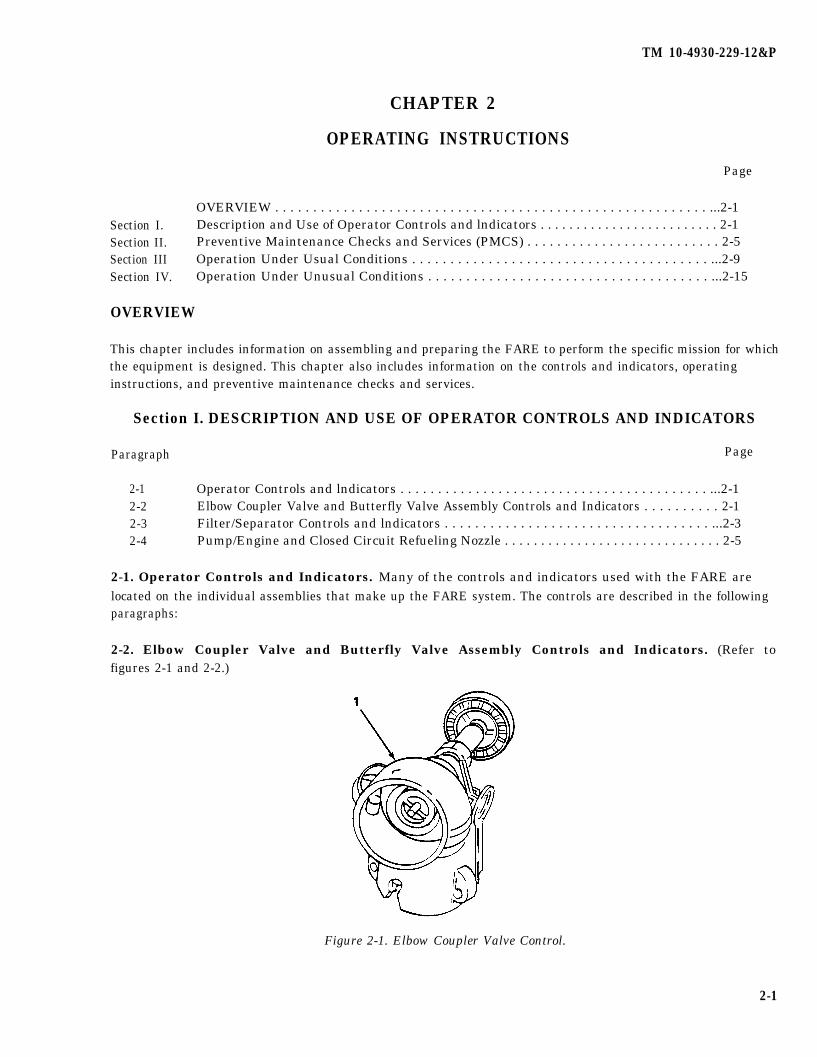
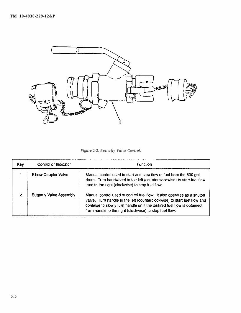
2-2. Elbow Coupler Valve and Butterfly Valve Assembly Controls and Indicators. (Refer tofigures 2-1 and 2-2.)
Figure 2-1. Elbow Coupler Valve Control.
2-1
TM 10-4930-229-12&P
Figure 2-2. Butterfly Valve Control.
2-2

TM 10-4930-229-12&P
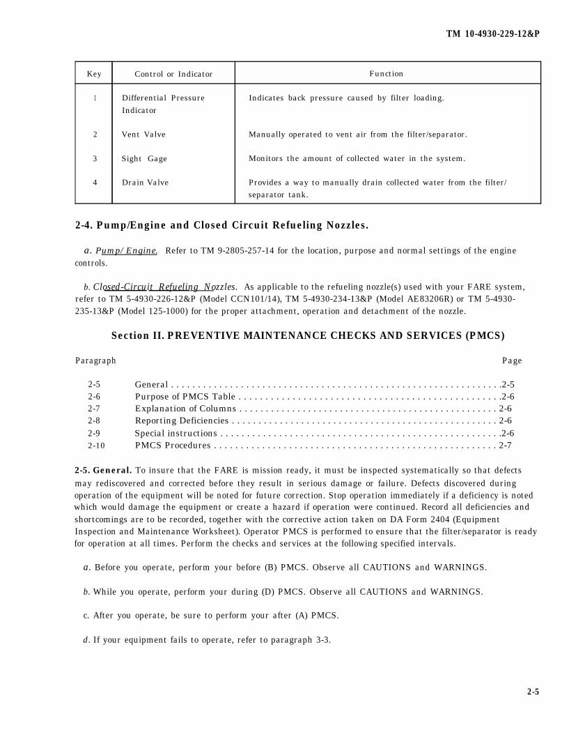
2-3. Filter/Separator Controls and Indicators. (Refer to figure 2-3.)
Figure 2-3. Filter/Separator Controls and Indicators (Sheet 1 of 2).
2-3

TM 10-4930-229-12&P
Figure 2-3. Filter/Separator Controls and Indicators (Sheet 2 of 2).
2-4
TM 10-4930-229-12&P
Key Control or Indicator Function
1 Differential Pressure Indicates back pressure caused by filter loading.Indicator
2 Vent Valve Manually operated to vent air from the filter/separator.
3 Sight Gage Monitors the amount of collected water in the system.
4 Drain Valve Provides a way to manually drain collected water from the filter/separator tank.
2-4. Pump/Engine and Closed Circuit Refueling Nozzles.
a. Pump/Engine. Refer to TM 9-2805-257-14 for the location, purpose and normal settings of the enginecontrols.
b. Closed-Circuit Refueling Nozzles. As applicable to the refueling nozzle(s) used with your FARE system,refer to TM 5-4930-226-12&P (Model CCN101/14), TM 5-4930-234-13&P (Model AE83206R) or TM 5-4930-235-13&P (Model 125-1000) for the proper attachment, operation and detachment of the nozzle.
Section II. PREVENTIVE MAINTENANCE CHECKS AND SERVICES (PMCS)
Paragraph Page
2-5 General . . . . . . . . . . . . . . . . . . . . . . . . . . . . . . . . . . . . . . . . . . . . . . . . . . . . . . . . . . . . . .2-52-6 Purpose of PMCS Table . . . . . . . . . . . . . . . . . . . . . . . . . . . . . . . . . . . . . . . . . . . . . . . . .2-62-7 Explanation of Columns . . . . . . . . . . . . . . . . . . . . . . . . . . . . . . . . . . . . . . . . . . . . . . . . . 2-62-8 Reporting Deficiencies . . . . . . . . . . . . . . . . . . . . . . . . . . . . . . . . . . . . . . . . . . . . . . . . . . 2-62-9 Special instructions . . . . . . . . . . . . . . . . . . . . . . . . . . . . . . . . . . . . . . . . . . . . . . . . . . . . .2-62-10 PMCS Procedures . . . . . . . . . . . . . . . . . . . . . . . . . . . . . . . . . . . . . . . . . . . . . . . . . . . . . 2-7
2-5. General. To insure that the FARE is mission ready, it must be inspected systematically so that defectsmay rediscovered and corrected before they result in serious damage or failure. Defects discovered duringoperation of the equipment will be noted for future correction. Stop operation immediately if a deficiency is notedwhich would damage the equipment or create a hazard if operation were continued. Record all deficiencies andshortcomings are to be recorded, together with the corrective action taken on DA Form 2404 (EquipmentInspection and Maintenance Worksheet). Operator PMCS is performed to ensure that the filter/separator is readyfor operation at all times. Perform the checks and services at the following specified intervals.
a. Before you operate, perform your before (B) PMCS. Observe all CAUTIONS and WARNINGS.
b. While you operate, perform your during (D) PMCS. Observe all CAUTIONS and WARNINGS.
c. After you operate, be sure to perform your after (A) PMCS.
d. If your equipment fails to operate, refer to paragraph 3-3.
2-5
TM 10-4930-229-12&P
2-6. Purpose of PMCS Table. The purpose of the PMCS table is to provide a systematic method ofinspecting and servicing the equipment. In this way, small defects can be detected early before they become amajor problem causing the equipment to fail to complete its mission. The PMCS table is arranged with theindividual PMCS procedures listed in sequence under assigned intervals. The most logical time (before, during, orafter operation) to perform each procedure determines the interval to which it is assigned. Make a habit of doingthe checks in the same order each time and anything wrong will be seen quickly. See paragraphs 2-5 and 2-7 foran explanation of the columns in table 2-1.
2-7. Explanation of Columns. The following is a list of the PMCS table column headings with adescription of the information found in each column.
a. Item No. This column shows the sequence in which the checks and services are to be performed, and isused to identify the equipment area on the Equipment Inspection and Maintenance Worksheet, DA Form 2404.
b. Interval. This column shows a dot. when each check is to be done.
c.Item to be Inspected/procedures. These columns identify the general area or specific part where the checkor service is to be done, and explains how to do it.
NOTE
The terms ready/available and mission capable refer to the same status: Equipment is onhand and is able to perform its combat mission. Refer to DA Pam 738-750.
d. Equipment is Not Ready/Available If This column list conditions that make the equipment unavailable foruse because it is unable to perform its mission, or because it would represent a safety hazard. Do not accept oroperate equipment with a condition in the “Equipment is Not Ready/Available If” column.
2-8. Reporting Deficiencies. If any problem with the equipment is discovered during PMCS or while it isbeing operated that cannot be corrected at the operator/crew maintenance level, it must be reported. Refer to DAPam 738-750 and report the deficiency using the proper forms.
2-9. Special lnstructions. Preventive maintenance is not limited to performing the checks and serviceslisted in the PMCS table.
WARNING
Dry cleaning solvent PD-680 used to clean parts is potentially dangerous to personneland property. Avoid repeated and prolonged skin contact. Do not use near open flameor excessive heat. Flash point of solvent is 100- 138°F (38–60°C).
a. Keep it Clean. Dirt, grease, oil, and debris get in the way and may cover up a serious problem. Clean asyou work and as needed. Use dry cleaning solvent on all metal surfaces. Use soap and water to clean rubber orplastic material.
b. Bolts,Nuts, and Screws. Check them all for obvious looseness, missing, bent, or broken condition. Youcan’t try them all with a tool, but look for chipped paint, bare metal, or rust around boltheads. If you find one youthink is loose, tighten it, or report it to unit maintenance if you can’t tighten it.
2-6
TM 10-4930-229-12&P
c. Fluid Lines. Look for wear, damage, and leaks. Make sure clamps and fittings are tight. Wet spots andstains around a fitting or connector can mean a leak. If a leak comes from a loose connector, tighten it. Ifsomething is broken or worn out, report it to unit maintenance.
d. Leakage Definitions. It is necessary for you to know how fluid leakage affects the status of your equipment.The following are definitions of the types/classes of leakage you need to know to be able to determine the statusof your equipment. Learn and be familiar with them. When in doubt, NOTIFY YOUR SUPERVISOR.
CAUTION
Equipment operation is allowable with minor leakage (Class I or II) of any fluid exceptfuel. Of course, consideration must be given to the fluid capacity in the item beingchecked/inspected. When in doubt, notify your supervisor.
When operating with Class I or II leaks, continue to check fluid level more often thanrequired in the PMCS.
Class III leaks should be reported to your supervisor or unit maintenance.
Leakage Definitions:
Class I Seepage of fluid (as indicated by wetness or discoloration) not great enough toform drops.
Class II Leakage of fluid great enough to form drops but not enough to cause drops todrip from item being checked/inspected.
Class III Leakage of fluid great enough to form drops that fall from the item beingchecked/inspected.
2-10. PMCS Procedures. Operator preventive maintenance checks and services are listed in table 2-1.
2-7

TM 10-4930-229-12&P
ItemNo.
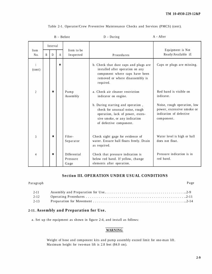
Table 2-1. Operator/Crew Preventive Maintenance Checks and Services (PMCS).
NOTE
Within designated interval, these checks are to be performed in the order listed.
B - Before D - During A - After
Interval—B—
●
—D—
—A—
Item to beInspected
1 Forward AreaRefuelingEquipment(FARE)Assembly
Procedures
a.
NOTE
Perform lubrication of the engineprior to or in conjunction with BeforePMCS. Refer to LO 9-2805-257-12.Keep engine and pump free of dirtand oil on all external surfaces.
Make the following walk-aroundchecks:
(1)
(2)
(3)
(4)
(5)
Check for fuel and oilleakage.
Check that hoses and fuellines are secure and properlyinstalled. Check for leaks.Check for separation ofmaterial, blisters and cuts.
Check that nozzles and fittingsare secure and properlyinstalled. Check for damage,badly scored surfaces, andmissing hardware.
Check grounding cables forloose connections, corrosion,and damage.
Check for loose or missinghardware, broken or crackedparts, and damage.
Equipment is NotReady/Available if:
Class Ill oil or any fuelleakage.
Hoses and fuel lines are notsecure or separation ofmaterial, blisters or cuts arepresent.
Nozzles or fittings areimproperly installed, badlyscored or missinghardware.
Cable is missing ordamaged.
Hardware is missing ordamaged.
2-8
TM 10-4930-229-12&P
Table 2-1. Operator/Crew Preventive Maintenance Checks and Services (PMCS) (cent).
B – Before D – During A - After
IntervalItem Item to be Equipment is Not
No. B D A Inspected Procedures Ready/Available if:
1 ● b. Check that dust caps and plugs are Caps or plugs are missing.(cont) installed after operation on any
component where caps have beenremoved or where disassembly isrequired.
2 ● Pump a. Check air cleaner restriction Red band is visible onAssembly indicator on engine. indicator.
b. During starting and operation , Noise, rough operation, lowcheck for unusual noise, rough power, excessive smoke oroperation, lack of power, exces- indication of defectivesive smoke, or any indication component.of defective component.
3 ● Filter- Check sight gage for evidence of Water level is high or ballSeparator water. Ensure ball floats freely. Drain does not float.
as required.
4 ● Differential Check that pressure indication is Pressure indication is inPressure below red band. If yellow, change red band.Gage elements after operation.
Section III. OPERATION UNDER USUAL CONDITIONS
Paragraph Page
2-11 Assembly and Preparation for Use.. . . . . . . . . . . . . . . . . . . . . . . . . . . . . . . . . . . . . . ...2-92-12 Operating Procedures . . . . . . . . . . . . . . . . . . . . . . . . . . . . . . . . . . . . . . . . . . . . . . ..2-112-13 Preparation for Movement . . . . . . . . . . . . . . . . . . . . . . . . . . . . . . . . . . . . . . . . . . . . ...2-14
2-11. Assembly and Preparation for Use.
a. Set up the equipment as shown in figure 2-4, and install as follows:
WARNING
Weight of hose and component kits and pump assembly exceed limit for one-man lift.Maximum height for two-man lift is 2.8 feet (84.0 cm).
2-9

TM 10-4930-229-12&P
Figure 2-4. Two-Point Refueling Operation.
2-10
TM 10-4930-229-12&P
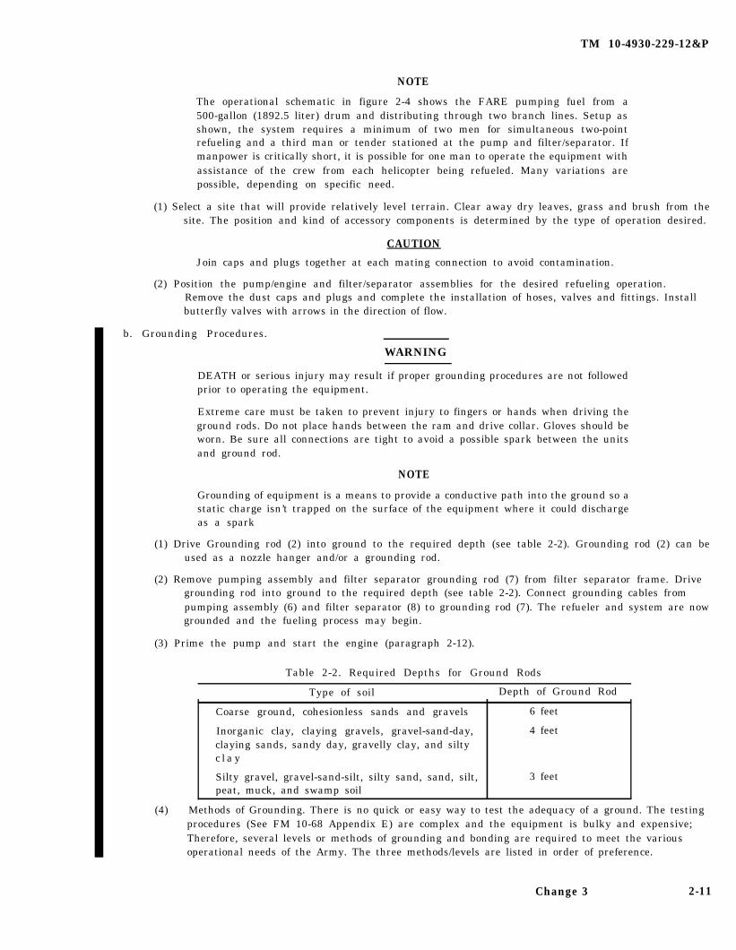
NOTE
The operational schematic in figure 2-4 shows the FARE pumping fuel from a500-gallon (1892.5 liter) drum and distributing through two branch lines. Setup asshown, the system requires a minimum of two men for simultaneous two-pointrefueling and a third man or tender stationed at the pump and filter/separator. Ifmanpower is critically short, it is possible for one man to operate the equipment withassistance of the crew from each helicopter being refueled. Many variations arepossible, depending on specific need.
(1) Select a site that will provide relatively level terrain. Clear away dry leaves, grass and brush from thesite. The position and kind of accessory components is determined by the type of operation desired.
CAUTION
Join caps and plugs together at each mating connection to avoid contamination.
(2) Position the pump/engine and filter/separator assemblies for the desired refueling operation.Remove the dust caps and plugs and complete the installation of hoses, valves and fittings. Installbutterfly valves with arrows in the direction of flow.
b. Grounding Procedures.
WARNING
DEATH or serious injury may result if proper grounding procedures are not followedprior to operating the equipment.
Extreme care must be taken to prevent injury to fingers or hands when driving theground rods. Do not place hands between the ram and drive collar. Gloves should beworn. Be sure all connections are tight to avoid a possible spark between the unitsand ground rod.
NOTE
Grounding of equipment is a means to provide a conductive path into the ground so astatic charge isn’t trapped on the surface of the equipment where it could dischargeas a spark
(1) Drive Grounding rod (2) into ground to the required depth (see table 2-2). Grounding rod (2) can beused as a nozzle hanger and/or a grounding rod.
(2) Remove pumping assembly and filter separator grounding rod (7) from filter separator frame. Drivegrounding rod into ground to the required depth (see table 2-2). Connect grounding cables frompumping assembly (6) and filter separator (8) to grounding rod (7). The refueler and system are nowgrounded and the fueling process may begin.
(3) Prime the pump and start the engine (paragraph 2-12).
Table 2-2. Required Depths for Ground Rods
Type of soil Depth of Ground Rod
(4)
Coarse ground, cohesionless sands and gravels
Inorganic clay, claying gravels, gravel-sand-day,claying sands, sandy day, gravelly clay, and siltyc l a y
Silty gravel, gravel-sand-silt, silty sand, sand, silt,peat, muck, and swamp soil
6 feet
4 feet
3 feet
Methods of Grounding. There is no quick or easy way to test the adequacy of a ground. The testingprocedures (See FM 10-68 Appendix E) are complex and the equipment is bulky and expensive;Therefore, several levels or methods of grounding and bonding are required to meet the variousoperational needs of the Army. The three methods/levels are listed in order of preference.
Change 3 2-11
TM 10-4930-229-12&P
(a) Method 1: equipment is grounded to a rod or rods that have measured resistance to groundequal to or less than 10,000 ohms. Ground the refueling system to this tested ground rod.Bond the nozzle to the vehicle/aircraft (see paragraph 2-12b). This method Is required,unless conditions, as described below, prevent its use. This method is the only standard ofgrounding acceptable, without authorization, at any fixed airfield or refueling point. It is thesafest method.
(b) Method 2: if equipment is not available to test resistance to ground, use method 2. Method 2 uses an untested ground - a grounding system based on the knowledge that damp earth willaccept and drain off an electrical charge. Use method 2 when the location, tactical situation, ortype of operation makes it impossible to test ground rods. Ground equipment to a rod or rodsdriven a specific depth into the ground depending on the type of soil at the site (see table 2-2).The depth to which the rods must be driven is determined by the normal depth of permanentground moisture in the various types of soils. The commander of the operating unit mustauthorize the use of method 2. This method is less desirable. Employ method 2 whenimpossible to use method 1.
WARNING
Death or serious injury may occur if proper bonding procedures are not followed (seeparagraph 2-12b). While using method 3, an obect with a different electrical potential(any object that is not part of the bonded system) should not come into contact withthe bonded equipment when a flammable vapor-air mixture maybe present.
(c) Method 3: When the climate, terrain, or tactical condition makes it impossible to secure asatisfactory ground rod, requirements to ground the fuel dispenser (system or refueler) maybewaived; however, the requirement to bond the fuel dispenser to the aircraft/vehicle maynot be waived under any circumstances. Method 3 relies on bonding alone (see paragraph2-12b ). Bonding is made between the aircraft/vehicle and the refueling system or refueleralong with the nozzle and the aircraft/vehicle. A contact between an unbended object and thesystem could produce a spark that could set off an explosion or fire. Method 3 procedures are authorized by the commander of the unit one organizational level above the operating unit.This is the least desirable method since it involves bonding only.
2-12. Operating Procedures.
a. Refueling Operations.
(1) Perform necessary Before PMCS (see table 2-1).
(2) Fill fuel tank on pump assembly with 5 gallons (18.925 liters) of approved fuel.
CAUTIONDo not start engine with pump housing dry. Do not operate over 2 minutes withouthaving fuel flow from the equipment.
(3) Prime pump by removing plug from priming port (see figure 1-2) and filling the housing with fuel.Open elbow coupler valve (figure 2-1) on the fuel storage drum and butterfly valve (figure 2-2)before starting engine.
(4) Open vent valve on filter/separator before starting the system (see figure 2-3).
CAUTION
if filter/separator should tip over during operation, stop pumping operationimmediately. Set the assembly upright and drain. Check connections, filter elements,sight gage and valve for damage. Remove cover and inspect interior before resumingoperation. Refer to TM 5-4330-217-12&P.
2-12
TM 10-4930-229-12&P
NOTE
Periodically during operation, check the differential pressure indicator (see figure2-3). If reading is red, shutdown the equipment and replace filter elements (refer toTM 5-4330-217-12&P). Monitor the sight gage during and after pumping operation.Drain off water when ball float rises halfway up in gage.
c. Bonding and Grounding Procedures. Refer to figure 2-4.
WARNING
DEATH or serious injury may result if proper bonding and grounding procedures arenot followed prior to operating the equipment.
NOTE
Bonding is the process that equalizes the charge on two unlike objects such as anaircraft and a refueling nozzle. It is done in order to prevent arcing, in the presence offlammable vapors, as the two objects are joined.
(1) Extend the grounding cable from the nozzle so it can be inserted into the vehicle/aircraft receptacle(if present). Otherwise, attach the grounding clip to a bare metal surface of the receiving vehicle/aircraft. Bond before the dust cap or gas tank cap is removed to prevent a spark occurring whenfuel vapor is present. Do not disconnect the bond until refueling is complete and the gas tank capand nozzle dust cap are replaced.
NOTE
Aircraft equipped with closed-circuit refueling receivers are refueled by attaching thenozzle to the fitting mounted on the aircraft fuel tank. Aircraft and other vehicles notequipped with closed-circuit refueling receivers are refueled by connecting thegravity-fill adapter to the nozzle.
(2) When refueling operations are completed, stop the engine in accordance with TM 9-2805-257-14.Hang nozzle and gravity-fill adapter on ground rod hangers. Do not lay nozzle or adapter on theground.
(3) Drain water from filter/separator. Leave vent open during shutdown unless possibility ofcontamination exists.
(4) Perform necessary After (A) PMCS (paragraph 2-5).
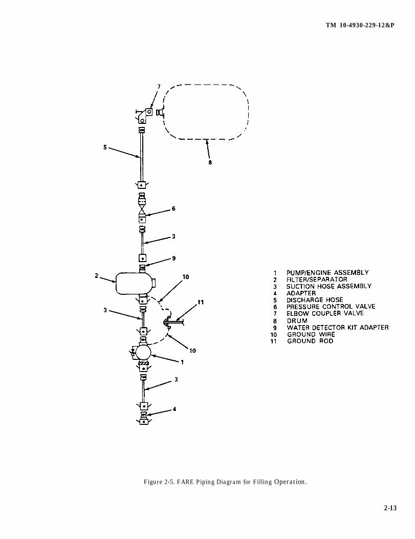
d. Filling a 500-GalIon Collapsible Drum. The piping diagram (figure 2-5) shows the FARE pumping fuel froman alternate fuel source to a 500-gallon (1892.5 liter) collapsible drum. Set up as shown, the FARE requiresa minimum of 2 men to operate, one man to act as a pump tender and a second man to dispense fuel intocontainers. Setting up the equipment for a filling operation is essentially the same as for a fueling operation,except for the specific selection of components for its configuration. Proceed as follows:
(1) Position pump/engine (1, figure 2-5) and filter/separator (2) assembly, suction hoses (3) and adapter(4). Remove dust caps and plugs, ensure gasket is in place and connect components.
Change 3 2-12.1 /(2-12.2 blank)

TM 10-4930-229-12&P
Figure 2-5. FARE Piping Diagram for Filling Operation.
2-13
TM 10-4930-229-12&P
(2) Roll out one or more lengths of discharge hose (5) and connect the pressure control valve (6) betweenthe filter/separator (2) and the discharge hose. Connect the hose through an elbow coupler valve (7) tothe 500-gallon (1892.5 liter) drum (8).
NOTE
Refer to TM 10-8110-201-14&P for operation of the pressure control valve.
(3) Secure all grounding cables (10) to ground rod (11) before starting a filling operation.
(4) Prime the pump and start the engine (para. 2-4).
(5) When fuel transfer operation is completed, stop the engine (para. 2-4).
c. Fuel Sampling. The water detector kit adapter contains a sampling probe which extends into the fuel flowingfrom the filter/separator outlet fitting. The Test Kit, Automotive and Aviation Fuels for Water and Solid Contamination(NSN 6640-00-244-9478) is attached to the adapter sampling probe. Install the adapter as follows:
NOTE
The Fuel Contamination Test Kit is not furnished with the FARE but is authorized tobe used with it.
(1) Referring to figure 1-4, look at the arrow on the hexagon nut to make certain the bevel on the probefaces into the fuel flow. The arrow should point in the direction of flow.
(2) Remove the dust cap from the filter/separator outlet coupling (see figure 1-3).
(3) Remove the dust plug from the adapter.
(4) Install, or make certain, that the gasket has been installed in the female coupling (figure 1 -4) and attachthe adapter to the filter/separator outlet coupling.
2-13. Preparation for Movement.
a. Stop the gasoline engine (para 2-4).
b. Close elbow coupling valve (1, figure 2-4) attached to the fuel tank.
WARNING
Do not smoke in area.
c. Open vent valve in filter/separator assembly cover and open the drain valve. Drain the filter/separator vesselof all water and fuel (refer to TM 5-4330-217-12&P).
d. Disconnect all suction hoses and fittings, allow fuel to drain into a proper container, then cap or plug all openfittings and suction hoses.
2-14
TM 10-4930-229-12&P
e. Disconnect discharge hoses, allow fuel to drain into a proper container; cap female end of hoses. Use thecapped end as a reel and roll up hose (figure 1-4, sheet 2). Plug other end of hose and stow rolled hose in the frame.
f. Drain fuel from pump casing into a proper container. Cap and plug pump inlet and outlet.
g. Remove ground rods.
h. Upon completion of a mission, stow all accessory components of equipment in spaces and compartmentsprovided in each frame and/or canvas container.
NOTE
Procedures for installation after moving the system are the same as those proce-dures covered in paragraph 2-11.
Section IV. OPERATION UNDER UNUSUAL CONDITIONS
Paragraph Page
2-14 Operation in Extreme Cold . . . . . . . . . . . . . . . . . . . . . . . . . . . . . . . . . . . . . . . . . . . . . . . . . . . . . ...2-152-15 Operation in Extreme Heat . . . . . . . . . . . . . . . . . . . . . . . . . . . . . . . . . . . . . . . . . . . . . . . . . . . . . ...2-152-16 Operation in Dusty or Sandy Areas... . . . . . . . . . . . . . . . . . . . . . . . . . . . . . . . . . . . . . . . . . . . ...2-152-17 Operation Under Rainy or Humid Conditions . . . . . . . . . . . . . . . . . . . . . . . . . . . . . . . . . . . . . ...2-152-18 Operation in Salt Water Areas . . . . . . . . . . . . . . . . . . . . . . . . . . . . . . . . . . . . . . . . . . . . . . . . . . . ...2-162-19 Operation at High Altitudes . . . . . . . . . . . . . . . . . . . . . . . . . . . . . . . . . . . . . . . . . . . . . . . . . . . . . ...2-16
2-14. Operation in Extreme Cold. The FARE will operate satisfactorily in extreme cold weather. Use properprecautions when handling fuel. Protect hose connections and nozzles from ice and snow. Inspect sight gage morefrequently for moisture. The low temperature operational limit is -25 degrees F. (-32 degrees C.).
2-15.taken.
2-16.
CAUTION
A hose full of fuel and closed at both ends must not be exposed to the sun forextended periods. Expansion of the fuel will damage the hose. Open vent valve onfilter/separator when not in use. Provide adequate shade when possible.
Operation in Extreme Heat. The FARE will operate in extreme heat when ordinary precautions areThe high temperature limit is 125 degrees F. (52 degrees C.).
Operation in Dusty or Sandy Areas. The FARE is adversely affected by dusty or sandy conditions.The nozzel spouts should be cleaned immediately before refueling operations start. Keep all dust caps in placeexcept when in use.
2-17. Operation Under Rainy or Humid Conditions. Keep nozzle spouts capped except when in use. Drynozzles thoroughly before refueling aircraft.
2-15

TM 10-4930-229-12&P
2-18. Operation in salt Water Areas. Operation in salt water areas presents corrosion problems. Keepexposed metal parts clean by washing with fresh water and drying thoroughly.
2-19. Operation at High Altitudes. Pump output may fall off slightly due to lower horsepower output of theMilitary Standard engine at high altitudes.
2-16
TM 10-4930-229-12&P
CHAPTER 3
OPERATOR MAINTENANCE INSTRUCTIONS
Page
OVERVIEW . . . . . . . . . . . . . . . . . . . . . . . . . . . . . . . . . . . . . . . . . . . . . . . . . . . . . . . . . . . . . . . 3-1Section I. Lubrication Instructions . . . . . . . . . . . . . . . . . . . . . . . . . . . . . . . . . . . . . . . . . . . . . . 3-1Section II. Operator Troubleshooting . . . . . . . . . . . . . . . . . . . . . . . . . . . . . . . . . . . . . . . . . . . . . . . . . .3-1Section III. Operator Maintenance . . . . . . . . . . . . . . . . . . . . . . . . . . . . . . . . . . . . . . . . . . . . . . . . . . . .3-4
OVERVIEW
This chapter contains operator level maintenance instructions. lt includes Lubrication instructions for the gasolineengine, troubleshooting procedures to isolate a malfunction to a specific component and maintenance proceduresfor the hoses, fittings and adapters, frame assembly, pump and engine assembly, filter/separator, collapsible drumsand the closed-circuit refueling nozzles.
Section I. LUBRICATION INSTRUCTIONS
Paragraph Page
3-1 General . . . . . . . . . . . . . . . . . . . . . . . . . . . . . . . . . . . . . . . . . . . . . . . . .3-1
3-1. General. Lubrication instructions for the Military Standard Engine (Mode 12A016-3) which is part of theFARE are contained in L0 9-2805-257-12. No other lubrication of system is required.
Section II OPERATOR TROUBLESHOOTING
Paragraph Page
3-2 General . . . . . . . . . . . . . . . . . . . . . . . . . . . . . . . . . . . . . . . . . . . . . . . . . . . . . . . . . . . . 3-13-3 Operator Troubleshooting Procedures . . . . . . . . . . . . . . . . . . . . . . . . . . . . . . . . . . . . .3-1
3-2. General. This section lists the common malfunctions you may find during operation of the FARE or itscomponents. Perform each test/inspection and corrective action in the order listed.
3-3. Operator Troubleshooting Procedures. Refer to the symptom index to locate the troubleshootingprocedure for the observed malfunction. Malfunctions which may occur during operation are listed in Table 3-1. Thismanual cannot Iist all malfunctions which may occur nor all of the probable causes and corrective actions. lf amalfunction is not listed or is not corrected by listed corrective action, notify your supervisor.
NOTE
Before you use this table, be sure you have performed all applicable operating checks.
3-1
TM 10-4930-229-12&P
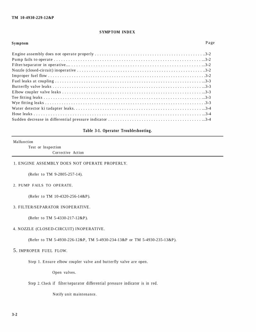
SYMPTOM INDEX
Symptom Page
Engine assembly does not operate properly . . . . . . . . . . . . . . . . . . . . . . . . . . . . . . . . . . . . . . . . . . . . . ..3-2Pump fails to operate . . . . . . . . . . . . . . . . . . . . . . . . . . . . . . . . . . . . . . . . . . . . . . . . . . . . . . . . . . . . . ...3-2Filter/separator in operative.... . . . . . . . . . . . . . . . . . . . . . . . . . . . . . . . . . . . . . . . . . . . . . . . . . . . . . ...3-2Nozzle (closed-circuit) inoperative . . . . . . . . . . . . . . . . . . . . . . . . . . . . . . . . . . . . . . . . . . . . . . . . . . . . ..3-2Improper fuel flow . . . . . . . . . . . . . . . . . . . . . . . . . . . . . . . . . . . . . . . . . . . . . . . . . . . . . . . . . . . . . . . . . . .3-2Fuel leaks at coupling . . . . . . . . . . . . . . . . . . . . . . . . . . . . . . . . . . . . . . . . . . . . . . . . . . . . . . . . . . . . . ...3-3Butterfly valve leaks . . . . . . . . . . . . . . . . . . . . . . . . . . . . . . . . . . . . . . . . . . . . . . . . . . . . . . . . . . . . . . ...3-3Elbow coupler valve leaks . . . . . . . . . . . . . . . . . . . . . . . . . . . . . . . . . . . . . . . . . . . . . . . . . . . . . . . . . . ...3-3Tee fitting leaks . . . . . . . . . . . . . . . . . . . . . . . . . . . . . . . . . . . . . . . . . . . . . . . . . . . . . . . . . . . . . . . . . . ...3-3Wye fitting leaks . . . . . . . . . . . . . . . . . . . . . . . . . . . . . . . . . . . . . . . . . . . . . . . . . . . . . . . . . . . . . . . . . . . .3-3Water detector ki tadapter leaks. . . . . . . . . . . . . . . . . . . . . . . . . . . . . . . . . . . . . . . . . . . . . . . . . . . . . ...3-4Hose leaks . . . . . . . . . . . . . . . . . . . . . . . . . . . . . . . . . . . . . . . . . . . . . . . . . . . . . . . . . . . . . . . . . . . . . ...3-4Sudden decrease in differential pressure indicator . . . . . . . . . . . . . . . . . . . . . . . . . . . . . . . . . . . . . . . ...3-4
Table 3-1. Operator Troubleshooting.
MalfunctionTest or lnspection
Corrective Action
1. ENGINE ASSEMBLY DOES NOT OPERATE PROPERLY.
(Refer to TM 9-2805-257-14).
2. PUMP FAILS TO OPERATE.
(Refer to TM 10-4320-256-14&P).
3. FILTER/SEPARATOR INOPERATIVE.
(Refer to TM 5-4330-217-12&P).
4. NOZZLE (CLOSED-CIRCUIT) INOPERATIVE.
(Refer to TM 5-4930-226-12&P, TM 5-4930-234-13&P or TM 5-4930-235-13&P).
5. IMPROPER FUEL FLOW.
Step 1. Ensure elbow coupler valve and butterfly valve are open.
Open valves.
Step 2. Check if filter/separator differential pressure indicator is in red.
Notify unit maintenance.
3-2

TM 10-4930-229-12&P
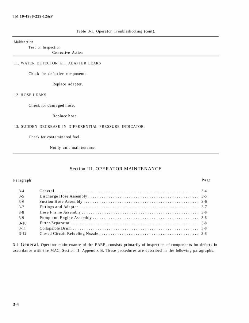
Table 3-1. Operator Troubleshooting (cont).
MalfunctionTest or Inspection
Corrective Action
5. IMPROPER FUEL FLOW (cent).
Step 3. Check pump/engine for proper operation.
(Refer to TM 10-4320-256-14&P).
Step 4. Check closed circuit refueling nozzle for proper operation.
(Refer to TM 5-4930-226-12&P, TM 5-4930-234-13&P or TM 5-4930-235-13& P.)
6. FUEL LEAKS AT COUPLING.
Check for defective gasket.
Replace gasket.
7. BUTTERFLY VALVE LEAKS.
Check for defective valve.
Replace valve.
8. ELBOW COUPLER VALVE LEAKS.
Check for defective valve.
Replace valve.
9. TEE FITTING LEAKS.
Check for defective fitting.
Replace fitting.
10. WYE FITTING LEAKS
Check for defective fitting.
Replace fitting.
3-3
TM 10-4930-229-12&P
Table 3-1. Operator Troubleshooting (cont).
MalfunctionTest or Inspection
Corrective Action
11. WATER DETECTOR KIT ADAPTER LEAKS
Check for defective components.
Replace adapter.
12. HOSE LEAKS
Check for damaged hose.
Replace hose.
13. SUDDEN DECREASE IN DIFFERENTIAL PRESSURE INDICATOR.
Check for contaminated fuel.
Notify unit maintenance.
Section III. OPERATOR MAINTENANCE
Paragraph
3-43-53-63-73-83-93-103-113-12
General . . . . . . . . . . . . . . . . . . . . . . . . . . . . . . . . . . . . . . . . . . . . . . . . . . . . . . . . . . . . . . .Discharge Hose Assembly . . . . . . . . . . . . . . . . . . . . . . . . . . . . . . . . . . . . . . . . . . . . . . . . .Suction Hose Assembly . . . . . . . . . . . . . . . . . . . . . . . . . . . . . . . . . . . . . . . . . . . . . . . . . . .Fittings and Adapter . . . . . . . . . . . . . . . . . . . . . . . . . . . . . . . . . . . . . . . . . . . . . . . . . . . . . .Hose Frame Assembly . . . . . . . . . . . . . . . . . . . . . . . . . . . . . . . . . . . . . . . . . . . . . . . . . . . .Pump and Engine Assembly . . . . . . . . . . . . . . . . . . . . . . . . . . . . . . . . . . . . . . . . . . . . . . .Fitter/Separator . . . . . . . . . . . . . . . . . . . . . . . . . . . . . . . . . . . . . . . . . . . . . . . . . . . . . . . . .Collapsible Drum . . . . . . . . . . . . . . . . . . . . . . . . . . . . . . . . . . . . . . . . . . . . . . . . . . . . . . . .Closed Circuit Refueling Nozzle . . . . . . . . . . . . . . . . . . . . . . . . . . . . . . . . . . . . . . . . . . . .
Page
3-43-53-63-73-83-83-83-83-8
3-4. General. Operator maintenance of the FARE, consists primarily of inspection of components for defects inaccordance with the MAC, Section II, Appendix B. These procedures are described in the following paragraphs.
3-4
TM 10-4930-229-12&P
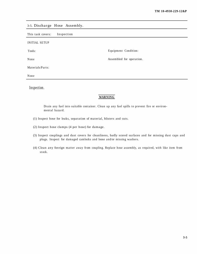
3-5. Discharge Hose Assembly.
This task covers: Inspection
INITIAL SETUP
Tools: Equipment Condition:
None Assembled for operation.
Materials/Parts:
None
Inspection.
WARNING
Drain any fuel into suitable container. Clean up any fuel spills to prevent fire or environ-mental hazard.
(1) Inspect hose for leaks, separation of material, blisters and cuts.
(2) Inspect hose clamps (4 per hose) for damage.
(3) Inspect couplings and dust covers for cleanliness, badly scored surfaces and for missing dust caps andplugs. Inspect for
(4) Clean any foreignstock.
damaged camlocks and loose and/or missing washers.
matter away from coupling. Replace hose assembly, as required, with like item from
3-5
TM 10-4930-229-12&P
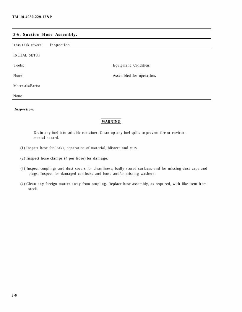
3-6. Suction Hose Assembly.
This task covers: Inspection
INITIAL SETUP
Tools:
None
Materials/Parts:
None
Equipment Condition:
Assembled for operation.
Inspection.
WARNING
Drain any fuel into suitable container. Clean up any fuel spills to prevent fire or environ-mental hazard.
(1) Inspect hose for leaks, separation of material, blisters and cuts.
(2) Inspect hose clamps (4 per hose) for damage.
(3) Inspect couplings and dust covers for cleanliness, badly scored surfaces and for missing dust caps andplugs. Inspect for damaged camlocks and loose and/or missing washers.
(4) Clean any foreign matter away from coupling. Replace hose assembly, as required, with like item fromstock.
3-6
TM 10-4930-229-12&P
3-7. Fittings and Adapter.
This task covers: Inspection
INITIAL SETUP
Tools: Equipment Condition:
None Assembled for operation.
Materials/Pads:
None
Inspection.
(1)
(2)
(3)
(4)
(5)
WARNING
Drain any fuel into suitable container. Clean up any fuel spills to prevent fire or environ-mental hazard.
inspect all fittings, coupling valves and water detector kit adapter for leaks.
Inspect couplings, dust plugs and dust covers for cleanliness, badly scored surfaces and for missinghardware.
Inspect for damaged camlocks and loose or missing gaskets.
Inspect water detector kit adapter probe
Replace any defective components with
for damage and clean
like items from stock.
as required.
3-7

TM 10-4930-229-12&P
3-8. Hose Frame Assembly.
This task covers: Inspection
INITIAL SETUP
Tools: Equipment Condition:
None Hoses and accessories separated from frame.
Materials/Parts:
None
Inspection.
(1) Inspect hose frame for broken welds, distorted tubular structure.
(2) inspect canvas storage bag for wear, tears and broken straps.
(3) Replace defective frame assembly with like item from stock.
3-9. Pump and Engine Assembly. Refer to TM 9-2805-257-14 for maintenance to be performed on theengine assembly by the operator or crew. Refer to TM 10-4320-256-14&P for maintenance to be performed onthe pump assembly by the operator or crew.
3-10. Filter/Separator. Refer to TM 5-4330-217-12&P for maintenance to be performed on the filter/separator by the operator or crew.
3-11. Collapsible Drum. Refer to TM 10-8110-201-14&P for maintenance to be performed on the collapsibledrum by the operator or crew.
3-12. Closed-Circuit Refueling Nozzle. Refer to TM 5-4930-226-12&P (Model CCN 101/14), TM5-4930-234-13&P (Model AE83206R) and TM 5-4930-235-13&P (Model 125-1000), as required, for maintenanceto be performed on the closed-circuit refueling nozzle(s) by the operator or crew.
3-8
TM 10-4930-229-12&P
CHAPTER 4
UNIT MAINTENANCE INSTRUCTIONS
Page
OVERVIEW . . . . . . . . . . . . . . . . . . . . . . . . . . . . . . . . . . . . . . . . . . . . . . . . . . . . . . . . . . . . . ...4-1Section I Repair Parts, Special Tools, Test, Measurement and Diagnostic
Equipment (TMDE) and Support Equipment . . . . . . . . . . . . . . . . . . . . . . . . . . . . . . . . ...4-1Section II Service Upon Receipt . . . . . . . . . . . . . . . . . . . . . . . . . . . . . . . . . . . . . . . . . . . . . . . . . . . . . ...4-1Section III Unit Preventive Maintenance Checks and Services (PMCS) . . . . . . . . . . . . . . . . . . . . . ...4-2Section IV Unit Troubleshooting . . . . . . . . . . . . . . . . . . . . . . . . . . . . . . . . . . . . . . . . . . . . ...-.......4-3Section V Unit Maintenance Procedures. . . . . . . . . . . . . . . . . . . . . . . . . . . . . . . . . . . . . . . . . . . . . . ...4-6Section VI Preparation for Shipment or Storage . . . . . . . . . . . . . . . . . . . . . . . . . . . . . . . . . . . . . . . . ...4-35
OVERVIEW
This chapter contains unit level maintenance instructions for the FARE. It includes references to the Repair Parts andSpecial Tools List in Appendix F, service upon receipt, unit PMCS and unit troubleshooting procedures. It alsoincludes unit maintenance procedures for the discharge and suction hoses, fittings and adapters, and hose frameassembly. Refer toTM 5-4930-235-13&P for repair of closed circuit nozzles. Refer to TM 5-4320-256-14&P forrepair of pump assembly. Refer to TM9-2805-257-14 for repair of engine assembly. Refer to TM5-4330-217-12&Pfor repair of filter/separator assembly. Refer to TM 10-8110-201-14&P for repair of the drum. Section VI whichdescribes preparation for storage or shipment, includes procedures for administrative, short term and intermediateterm storage.
Section I. REPAIR PARTS, SPECIAL TOOLS, TEST, MEASUREMENT ANDDIAGNOSTIC EQUIPMENT (TMDE) AND SUPPORT EQUIPMENT
Paragraph Page
4-1 Special Tools, TMDE and Support Equipment . . . . . . . . . . . . . . . . . . . . . . . . . . . . . . . . . . . . . ...4-14-2 Repair Parts . . . . . . . . . . . . . . . . . . . . . . . . . . . . . . . . . . . . . . . . . . . . . . . . . . . .. .4-1
4-1. Special Tools, TMDE and Support Equipment. No special tools are required for unit maintenanceof the FARE. TMDE and support equipment are listed in the Maintenance Allocation Chart (MAC).
4-2. Repair parts. Repair parts required for maintenance of the FARE are listed in the Repair Parts and SpecialTools List (RPSTL), Appendix F of this manual.
Section II. SERVICE UPON RECEIPT
Paragraph Page
4-3 Unloading . . . . . . . . . . . . . . . . . . . . . . . . . . . . . . . . . . . . . . . . . . . . . . . . ...4-24-4 Unpacking . . . . . . . . . . . . . . . . . . . . . . . . . . . . . . . . . . . . . . . . . . . . . .... 4-24-5 Inspection and Service . . . . . . . . . . . . . . . . . . . . . . . . . . . . . . . . . . . . . . . . . . ... 4-2
4-1
TM 10-4930-229-12&P
4-3. Unloading. Take care when unloading equipment from transport vehicle to avoid damage.
WARNING
Weight of hose and component kits and pump/engine assembly exceed limit for one-manlift. Maximum height for two-man lift is 2.8 feet (84.0 cm).
4-4. Unpacking. Carefully unpack each carton taking care to examine all packing material before discarding.Check equipment against the packing slip to see if shipment is complete. Report all discrepancies in accordancewith DA PAM 738-750.
4-5.
a.
b.
c.
Inspection and Service.
Inspect equipment for damage incurred during shipment and for missing parts. Carefully inspect hoseassemblies for damaged couplings and inspect hoses for cuts and excessive wear. If equipment has beendamaged, report damage on SF Form 368, Product Quality Deficiency Report.
Check that ground cables are securely fastened to pump/engine assembly and filter/separator assembly.Make sure that grounding clip and plug at free ends of nozzle grounding cables are securely fastened toground cable and that cable is attached to nozzle. Inspect all ground cables for broken or damagedcondition.
Perform unit level PMCS and operator Before (B) PMCS before operating equipment.
Section III. UNIT PREVENTIVE MAINTENANCE CHECKS AND SERVICES (PMCS)
Paragraph Page
4-6 General . . . . . . . . . . . . . . . . . . . . . . . . . . . . . . . . . . . . . . . . . . . . . . . . . . . . . . . . . . . . ...4-2
4-6. General. To ensure that FARE is ready for operation at all times, it must be inspected systematically sodefects may be discovered and corrected before they result in serious damage or failure. The necessarypreventive maintenance checks and services are listed in table 4-1. Defects discovered during operation ofsystem shall be noted for future correction to be made as soon as operation has ceased. Stop operationimmediately if a deficiency is noted during operation, which would damage the equipment if operation werecontinued. If equipment fails to operate, troubleshoot with the proper equipment. Report any deficiencies usingthe proper forms. (See DA PAM 738-750).
4-2
TM 10-4930-229-12&P
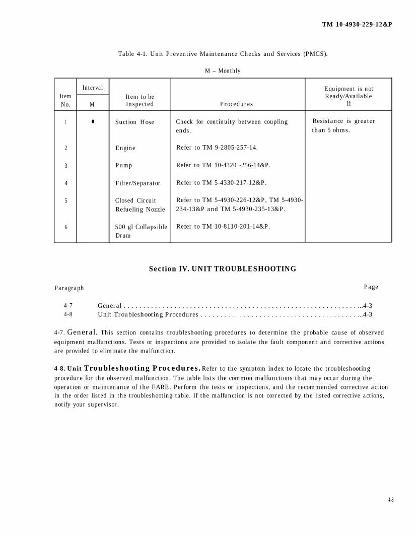
Table 4-1. Unit Preventive Maintenance Checks and Services (PMCS).
M – Monthly
Interval Equipment is notItem Item to be Ready/AvailableNo. M Inspected Procedures If:
1 ● Suction Hose Check for continuity between coupling Resistance is greaterends. than 5 ohms.
2 Engine Refer to TM 9-2805-257-14.
3 Pump Refer to TM 10-4320 -256-14&P.
4 Filter/Separator Refer to TM 5-4330-217-12&P.
5 Closed Circuit Refer to TM 5-4930-226-12&P, TM 5-4930-Refueling Nozzle 234-13&P and TM 5-4930-235-13&P.
6 500 gl Collapsible Refer to TM 10-8110-201-14&P.Drum
Section IV. UNIT TROUBLESHOOTING
Paragraph Page
4-7 General . . . . . . . . . . . . . . . . . . . . . . . . . . . . . . . . . . . . . . . . . . . . . . . . . . . . . . . . . . . . ...4-34-8 Unit Troubleshooting Procedures . . . . . . . . . . . . . . . . . . . . . . . . . . . . . . . . . . . . . . . . ...4-3
4-7. General. This section contains troubleshooting procedures to determine the probable cause of observedequipment malfunctions. Tests or inspections are provided to isolate the fault component and corrective actionsare provided to eliminate the malfunction.
4-8. Unit Troubleshooting Procedures. Refer to the symptom index to locate the troubleshootingprocedure for the observed malfunction. The table lists the common malfunctions that may occur during theoperation or maintenance of the FARE. Perform the tests or inspections, and the recommended corrective actionin the order listed in the troubleshooting table. If the malfunction is not corrected by the listed corrective actions,notify your supervisor.
4-3

TM 10-4930-229-12&P
SYMPTOM INDEX
Symptom Page
Engine assembly does not operate properly . . . . . . . . . . . . . . . . . . . . . . . . . . . . . . . . . . . . . . . . . . . . . . . . . . . . ..4-4Pump fails cooperate . . . . . . . . . . . . . . . . . . . . . . . . . . . . . . . . . . . . . . . . . . . . . . . . . . . . . . . . . . . . . . . . . . . . . . . ...4-4Filter/separator inoperative..... . . . . . . . . . . . . . . . . . . . . . . . . . . . . . . . . . . . . . . . . . . . . . . . . . . . . . . . . . . . . . ...4-4Nozzle (closed-circuit) inoperative . . . . . . . . . . . . . . . . . . . . . . . . . . . . . . . . . . . . . . . . . . . . . . . . . . . . . . . . . . . . ...4-4Improper fuel flow . . . . . . . . . . . . . . . . . . . . . . . . . . . . . . . . . . . . . . . . . . . . . . . . . . . . . . . . . . . . . . . . . . . . . . . . . . ...4-4Fuel leaks at coupling . . . . . . . . . . . . . . . . . . . . . . . . . . . . . . . . . . . . . . . . . . . . . . . . . . . . . . . . . . . . . . . . . . . . . . . . ..4-5Butterfly valve leaks . . . . . . . . . . . . . . . . . . . . . . . . . . . . . . . . . . . . . . . . . . . . . . . . . . . . . . . . . . . . . . . . . . . . . . . . ...4-5Elbow coupler valve leaks . . . . . . . . . . . . . . . . . . . . . . . . . . . . . . . . . . . . . . . . . . . . . . . . . . . . . . . . . . . . . . . . . . . ...4-5Tee fitting leaks . . . . . . . . . . . . . . . . . . . . . . . . . . . . . . . . . . . . . . . . . . . . . . . . . . . . . . . . . . . . . . . . . . . . . . . . . . . . ...4-5Wye fitting leaks . . . . . . . . . . . . . . . . . . . . . . . . . . . . . . . . . . . . . . . . . . . . . . . . . . . . . . . . . . . . . . . . . . . . . . . . . . . ...4-5Water detector kit adapter leaks. . . . . . . . . . . . . . . . . . . . . . . . . . . . . . . . . . . . . . . . . . . . . . . . . . . . . . . . . . . . . . ...4-5Hose leaks . . . . . . . . . . . . . . . . . . . . . . . . . . . . . . . . . . . . . . . . . . . . . . . . . . . . . . . . . . . . . . . . . . . . . . . . . . . . . . . . ...4-6Sudden decrease in differential pressure indicator and/or contaminated fuel . . . . . . . . . . . . . . . . . . . . . . . . ...4-6
Table 4-2. Unit Troubleshooting.
MalfunctionTest or lnspection
Corrective Action
1.
2.
3.
4.
5.
ENGINE ASSEMBLY DOES NOT OPERATE PROPERLY.
(Refer to TM 9-2805-257-1 4.)
PUMP FAILS TO OPERATE.
(Refer to TM 10-4320-256-14&P.)
FILTER/SEPARATOR INOPERATIVE.
(Refer to TM 5-4330-217-12&P.)
NOZZLE (CLOSED-CIRCUIT) INOPERATIVE.
(Refer to TM 5-4930-226-12&P, TM 5-4930-234-13&P,orTM 5-4930-235-13&P.)
IMPROPER FUEL FLOW.
Step 1. Check if filter/separator differential pressure indicator is in red.
Replace filter elements.
Step 2. Check pump/engine for proper operation.
(Refer to TM 10-4320-256-14&P and TM 9-2805-257-1 4.)
4-4
TM 10-4930-229-12&P
Table 4-2. Unit Troubleshooting (cont).
MalfunctionTest or Inspection
Corrective Action
5. IMPROPER FUEL FLOW (cont).
Step 3. Check closed circuit refueling nozzle for proper operation.
(Refer to TM 5-4930 -226-12&P, TM 5-4930-234-13&P or TM 5-4930-235-13&P.)
6. FUEL LEAKS AT COUPLING.
Check for defective coupling.
Replace coupling (see para. 4-10 or 4-11).
7. BUTTERFLY VALVE LEAKS.
Check for defective valve.
Repair valve (see para. 4-13).
8. ELBOW COUPLER VALVE LEAKS.
Check for defective valve.
Repair valve (see para. 4-14).
9. TEE FITTING LEAKS.
Check for defective fitting.
Repair fitting (see para. 4-15).
10. WYE FITTING LEAKS.
Check for defective fitting,
Repair fitting (see para. 4-18).
11. WATER DETECTOR KIT ADAPTER LEAKS.
Repair adapter (see para. 4-19).
Check for defective components.
4-5

TM 10-4930-229-12&P
Table 4-2. Unit Troubleshooting (cont).
MalfunctionTest or Inspection
Corrective Action
12. HOSE LEAKS.
Check for damaged hose.
Repair hose (see para. 4-10 or 4-11).
SUDDEN DECREASE IN DIFFERENTIAL PRESSURE INDICATOR AND/OR CONTAMINATED FUEL.
Check for damaged fuel filter elements.
Replace filter elements.
13.
Paragraph
4-94-104-114-124-134-144-154-164-174-184-194-20
Section V. UNIT MAINTENANCE PROCEDURES
Page
General . . . . . . . . . . . . . . . . . . . . . . . . . . . . . . . . . . . . . . . . . . . . . . . . . . . . . . . . . . . . ...4-6Hose Assembly, Discharge . . . . . . . . . . . . . . . . . . . . . . . . . . . . . . . . . . . . . . . . . . . . . ...4-8Hose Assembly, Suction . . . . . . . . . . . . . . . . . . . . . . . . . . . . . . . . . . . . . . . . . . . . . . . ...4-11Ground Rod . . . . . . . . . . . . . . . . . . . . . . . . . . . . . . . . . . . . . . . . . . . . . . . . . . . . . . . . . ...4-13Valve Assembly, Butterfly . . . . . . . . . . . . . . . . . . . . . . . . . . . . . . . . . . . . . . . . . . . . . . ...4-14Valve, Elbow Coupler . . . . . . . . . . . . . . . . . . . . . . . . . . . . . . . . . . . . . . . . . . . . . . . . . . . . 4-18Tee Fitting Assembly . . . . . . . . . . . . . . . . . . . . . . . . . . . . . . . . . . . . . . . . . . . . . . . . . . ...4-21Adapter Assembly . . . . . . . . . . . . . . . . . . . . . . . . . . . . . . . . . . . . . . . . . . . . . . . . . . . . ...4-23Adapter, Nozzle . . . . . . . . . . . . . . . . . . . . . . . . . . . . . . . . . . . . . . . . . . . . . . . . . . . . . . ...4-25Wye Fitting Assembly . . . . . . . . . . . . . . . . . . . . . . . . . . . . . . . . . . . . . . . . . . . . . . . . . . . . 4-27Adapter, Water Detector Kit.... . . . . . . . . . . . . . . . . . . . . . . . . . . . . . . . . . . . . . . . . . ...4-30Frame Assembly . . . . . . . . . . . . . . . . . . . . . . . . . . . . . . . . . . . . . . . . . . . . . . . . . . . . . ...4-33
4-9. General. This section contains unit maintenance information for the discharge and suction hoseassemblies, the butterfly valve assembly, elbow coupler valve, tee and wye fitting assemblies. Unit maintenanceinformation for other components and accessories of the FARE can be found in the following publications:
a. For removal of military standard engine, refer to TM 10-4320-256-14&P.
b. For repair and overhaul of the military standard engine, refer to TM 9-2805-257-14.
c. For repair of the pump/engine frame assembly, refer to TM 10-4320-256-14&P.
d. For overhaul of the pump assembly, refer to TM 10-4320-256-14&P.
4-6

TM 10-4930-229-12&P
e. For repair of the filter/separator refer to TM 5-4330-217-12&P.
f. For repair of the closed-circuit nozzle assemblies refer toTM 5-4930-226-12&P (Model CCN 101/14),TM 5-4930-234-13&P (Model AE83206R) and TM 5-4930-235-13&P (Model 125-1000).
g. For repair of the canvas accessory containers, refer to FM 10-16.
4-7
TM 10-4930-229-12&P
4-10. Hose Assembly, Discharge.
This task covers: a. Repair b. Replace
INITIAL SETUP
Tools: General Safety Instructions:
Banding Tool, Item 2, Section III, Appendix BTool Kit, General Mechanic’s, Item 1, Section III,
Appendix B ●
Materials/Paris:
Seals, 1/2 In. Strapping, Item 1, Appendix E ●
Strapping, 1/2 In., Item 2, Appendix E
Equipment Condition:
FARE shutdown per para. 2-12.
WARNING
Do not smoke or use an open flame in thevicinity of the FARE, failure to comply mayresult in personnel injury.
Drain any fuel into suitable container. Clean upany fuel spills to prevent fire or environmentalhazard.
a. Repair. (figure 4-1)
(1) Couplings. To replace a defective coupling, proceed as follows:
(a)
(b)
(c)
(d)
(e)
(f)
(g)
Cut band and remove damaged coupling (1).
Install barbed end of new coupling in hose (2) end.
Slide buckle (3) on banding material (4), bend approximately 1 in. of banding material under buckle.Wrap banding material around hose twice passing through buckle each time. Position bandapproximately 1/2 in. from shoulder of coupling.
Place band in open slot of banding tool nose (5) and in slide.
With thumb on band gripper lever (6), apply tension by turning handle (7) of tool clockwise. Aftertension is created, it is no longer necessary to hold band gripper lever as it locks itself under tension.
Place finger on banding material (4) at buckle bridge while tensioning with tool handle (7) in aclockwise direction.
When banding material stops moving through buckle (3) as handle (7) turns, stop turning. Maximumtension is being exerted by banding material around hose.
WARNING
Failure to back off with tension handle throughout entire course of rollmay result in breaking of band, and injury to personnel.
4-8
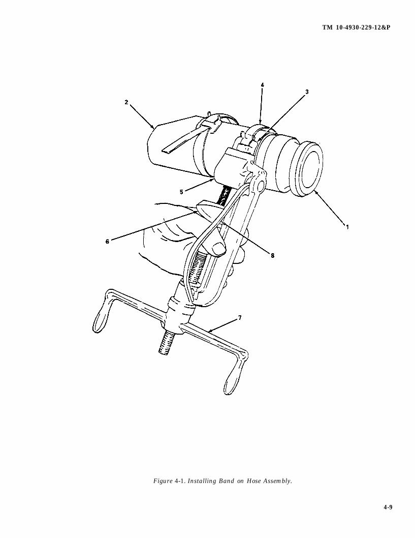
TM 10-4930-229-12&P
Figure 4-1. Installing Band on Hose Assembly.
4-9
TM 10-4930-229-12&P
4-10. Hose Assembly, Discharge (cont).
(h) Roll tool over buckle, backing off with tension handle throughout entire rolling operation.
(i) Pull cutting handle (8) to cut band.
(j) Remove tool, holding stub of band down with thumb. Clinch stub by hammering down buckle ears.
(k) Repeat steps (d) through (j); positioning band approximately 2 in. from shoulder clamp.
(2) Discharge hose. Repair a damaged discharge hose as follows:
(a) Cut hose to remove damaged section.
(b) If damaged area is within 10 feet (304.8 cm) of end of hose, remove fitting from short length of hoseand reinstall in longer section using procedure in (1), above.
(c) If damaged section is more than 10 feet (304.8 cm) from end of hose, replace with like item fromstock.
b. Replace.
(1) Removal.
(a) Pull upon camlock levers on discharge hoses and closed circuit nozzle.
(b) Remove discharge hoses from wye fitting and closed circuit nozzle.
(2) Installation.
(a) Connect discharge hoses to wye fitting and closed circuit nozzle.
(b) Push down on camlock levers to secure discharge hoses.
4-10
TM 10-4930-229-12&P
4-11. Hose Assembly, Suction.
This task covers: a. Repair b. Test c. Replace
INITIAL SETUP
Tools:
Banding Tool, Item 2, Section III, Appendix BTool Kit, General Mechanic's, Item 1, Section III,
Appendix BMultimeter, Digital, Item 3, Section III, Appendix B
Materials/Parts:
Seals, 1/2 In., Item 1, Appendix EStrapping, 1/2 In., Item 2, Appendix E
Equipment Condition:
FARE shutdown per para. 2-12.
General Safety Instructions:
WARNING
● Do not smoke or use an open flame in thevicinity of the FARE, failure to comply mayresult in personnel injury.
● Drain any fuel into suitable container. Clean upany fuel spills to prevent fire or environmentalhazard.
a. Repair. (figure 4-1)
(1) Couplings. To replace a defective coupling, proceed as follows:
(a)
(b)
(c)
(d)
(e)
(f)
(g)
Cut band and remove damaged coupling (1).
Ensure static wire extends beyond end of hose (2) a minimum of 1/4 in. Install barbed end of newcoupling in hose end. Ensure static wire is in contact with coupling.
Slide buckle (3) on banding material (4), bend approximately 1 in. of banding material under buckle.Wrap banding material around hose twice running end through each time.
Place band in open slot of banding tool nose (5) and in slide.
With thumb on band gripper lever (6), apply tension by turning handle (7) of tool clockwise. Aftertension is created, it is no longer necessary to hold band gripper lever as it locks itself under tension.
Place finger on banding material (4) at buckle bridge while tensioning with tool handle (7) in aclockwise direction.
When banding material stops moving through buckle (3) as handle (7) turns, stop turning. Maximumtension is exerted by banding material around hose.
WARNING
Failure to back off with tension handle throughout entire course of rollmay result in breaking of band, and injury to personnel.
4-11

TM 10-4930-229-12&P
4-11. Hose Assembly, Suction (cont).
(h) Roll tool over buckle, backing off with tension handle throughout entire rolling operation.
(i) Pull cutting handle (8) to cut band.
(j) Remove tool, holding stub of band down with thumb. Clinch stub by hammering down buckle ears.
(k) Repeat steps (d) through (j); positioning band approximately 2 in. from shoulder of coupling.
(l) Perform test as outlined in (b) above.
(2) Suction hose. Repair a damaged suction hose as follows:
(a) If hose is damaged within one foot (30.48 cm) of end, cut off damaged portion and install coupling asin (1) above. Make sure static wire extends 1/4 inch beyond cut end.
(b) If damaged section is more than one foot from end, replace complete hose and reinstall couplings asin (1) above.
b. Test.
NOTE
Suction hose assembly should be tested every thirty days or whenever hose hasbeen damaged.
(1) Touch each probe of multimeter to opposite end hose coupling half. Use a multimeter and perform acontinuity test on the suction hose to insure the wires in the suction hose are not broken.
(2) The resistance reading should be 5 ohms or less. Repair hose assembly if resistance is greater than 5ohms.
(3) No hydrostatic test is required on the discharge hose and suction hose.
c. Replace.
(1) Removal.
(a) Pull up on camlock levers on butterfly valve and suction hoses.
(b) Remove suction hoses.
(2) Installation.
(a) Connect suction hose to butterfly valve.
(b) Push down on camlock levers to secure suction hose.
4-12
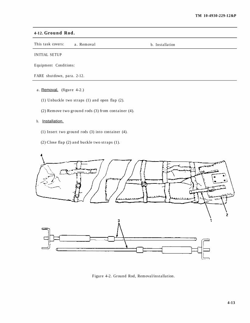
TM 10-4930-229-12&P
4-12. Ground Rod.
This task covers: a. Removal b. Installation
INITIAL SETUP
Equipment Conditions:
FARE shutdown, para. 2-12.
a. Removal. (figure 4-2.)
(1) Unbuckle two straps (1) and open flap (2).
(2) Remove two ground rods (3) from container (4).
b. Installation.
(1) Insert two ground rods (3) into container (4).
(2) Close flap (2) and buckle two straps (1).
Figure 4-2. Ground Rod, Removal/installation.
4-13
TM 10-4930-229-12&P
4-13. Valve Assembly, Butterfly.
This task covers: a. Repair b. Replace
INITIAL SETUP
Tools: General Safety Instructions:
Tool Kit, General Mechanic’s, Item 1, Section III,Appendix B
●
Materials/Parts:
Gaskets, Appendix FSealing Compound, Item 3, Appendix E ●
Equipment Conditions:
FARE shutdown, para 2-12.Inspected, para. 3-7
WARNING
Do not smoke or use an open flame in thevicinity of the FARE, failure to comply mayresult in personnel injury.
Drain any fuel into suitable container. Clean upany fuel spills to prevent fire or environmentalhazard.
a. Repair. (figure 4-3)
(1) Disassembly.
(a)
(b)
(c)
(d)
(e)
(f)
(g)
(h)
Check butterfly valve lever for ease of operation, and damaged or missing parts.
WARNING
Cleaning solvent, Federal Specification PD-680, is toxic and flammable.Use only in a well-ventilated area. Avoid prolonged breathing of fumes.Keep solvent away from flames. Do not use in excessive amounts.Avoid skin contact.
Clean butterfly valve with cleaning solvent, allow to dry.
Remove setscrew (1), handle (2) and cap (3) from shaft (4).
Remove two screws (5).
Pull shaft (4) straight out, then remove disc (6).
Remove non-metallic washer (7) and metallic washer (8) from shaft (4).
Remove O-ring (9) from valve body (10).
Remove pin (11 ), then remove shaft (12) and O-ring (13).
4-14
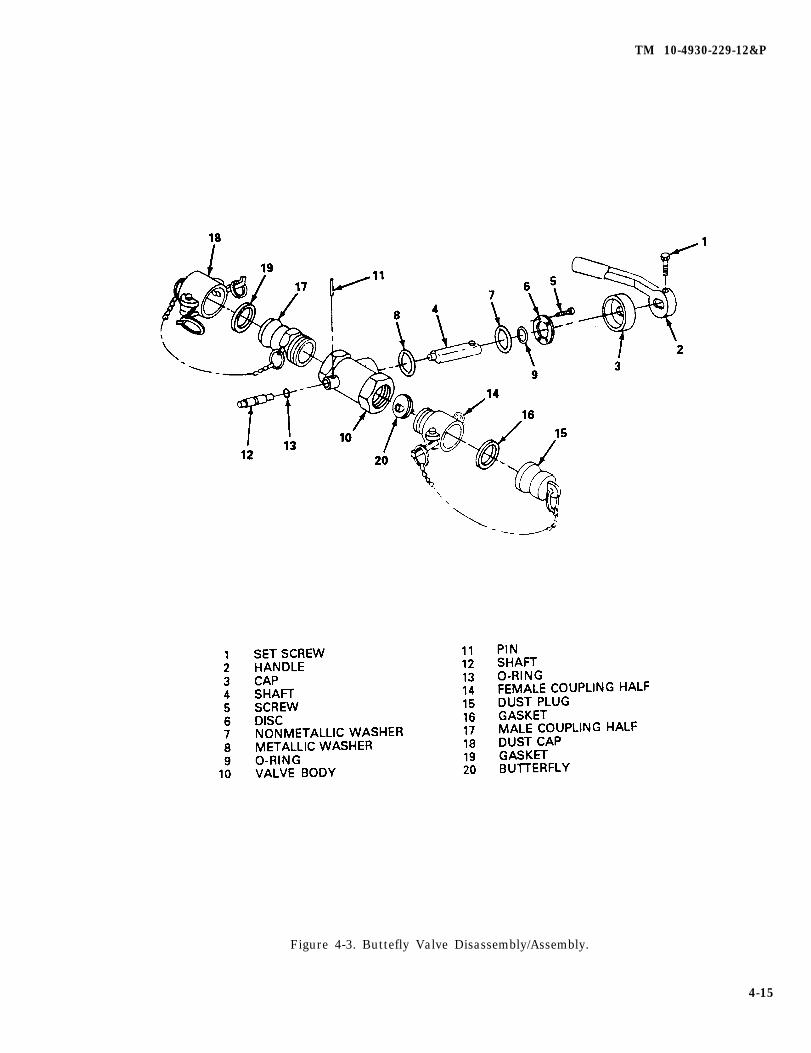
TM 10-4930-229-12&P
Figure 4-3. Buttefly Valve Disassembly/Assembly.
4-15
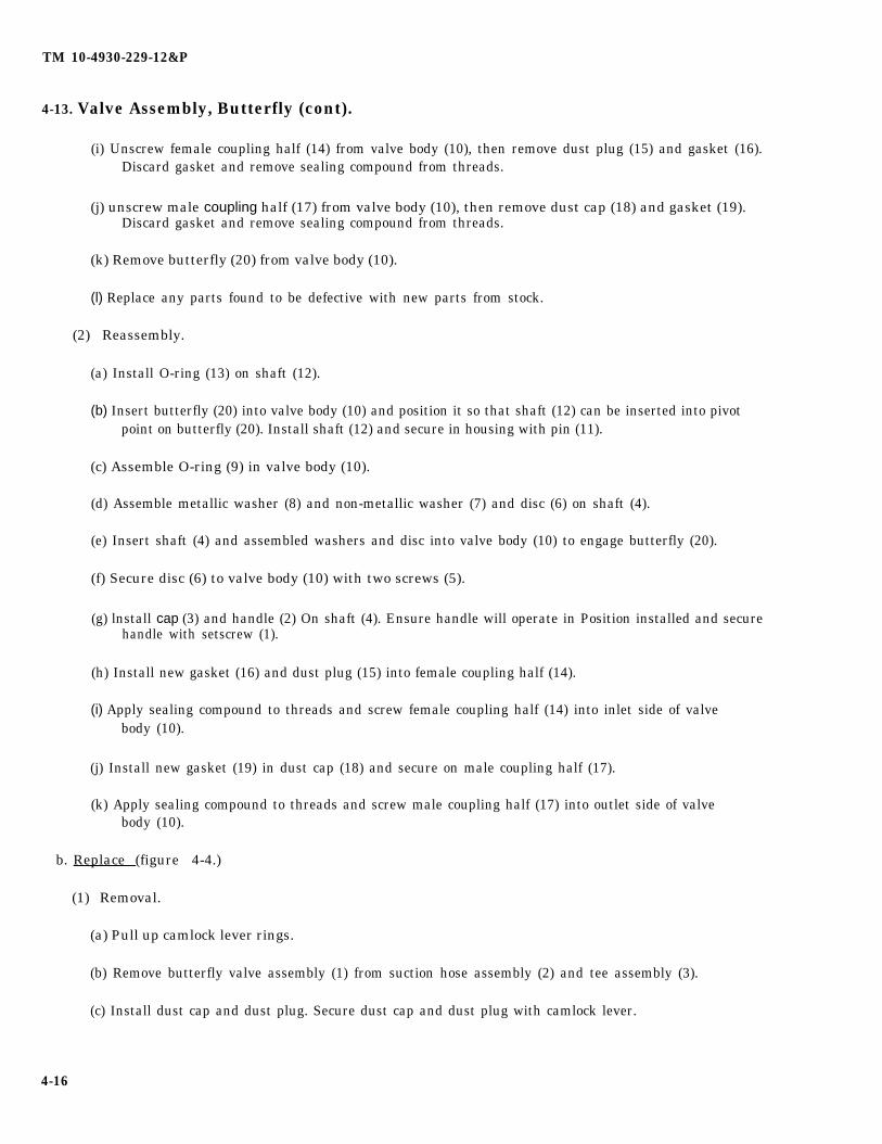
TM 10-4930-229-12&P
4-13. Valve Assembly, Butterfly (cont).
(i) Unscrew female coupling half (14) from valve body (10), then remove dust plug (15) and gasket (16).Discard gasket and remove sealing compound from threads.
(j) unscrew male coupling half (17) from valve body (10), then remove dust cap (18) and gasket (19).Discard gasket and remove sealing compound from threads.
(k) Remove butterfly (20) from valve body (10).
(l) Replace any parts found to be defective with new parts from stock.
(2) Reassembly.
(a) Install O-ring (13) on shaft (12).
(b) Insert butterfly (20) into valve body (10) and position it so that shaft (12) can be inserted into pivotpoint on butterfly (20). Install shaft (12) and secure in housing with pin (11).
(c) Assemble O-ring (9) in valve body (10).
(d) Assemble metallic washer (8) and non-metallic washer (7) and disc (6) on shaft (4).
(e) Insert shaft (4) and assembled washers and disc into valve body (10) to engage butterfly (20).
(f) Secure disc (6) to valve body (10) with two screws (5).
(g) lnstall cap (3) and handle (2) On shaft (4). Ensure handle will operate in Position installed and securehandle with setscrew (1).
(h) Install new gasket (16) and dust plug (15) into female coupling half (14).
(i) Apply sealing compound to threads and screw female coupling half (14) into inlet side of valvebody (10).
(j) Install new gasket (19) in dust cap (18) and secure on male coupling half (17).
(k) Apply sealing compound to threads and screw male coupling half (17) into outlet side of valvebody (10).
b. Replace (figure 4-4.)
(1) Removal.
(a) Pull up camlock lever rings.
(b) Remove butterfly valve assembly (1) from suction hose assembly (2) and tee assembly (3).
(c) Install dust cap and dust plug. Secure dust cap and dust plug with camlock lever.
4-16
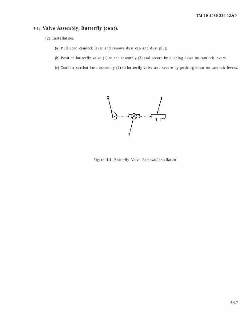
TM 10-4930-229-12&P
4-13. Valve Assembly, Butterfly (cont).
(2) Installation.
(a) Pull upon camlock lever and remove dust cap and dust plug.
(b) Position butterfly valve (1) on tee assembly (3) and secure by pushing down on camlock levers.
(c) Connect suction hose assembly (2) to butterfly valve and secure by pushing down on camlock levers.
Figure 4-4. Butterfly Valve Removal/Installation.
4-17

TM 10-4930-229-12&P
4-14. Valve, Elbow Coupler.
This task covers: a. Repair b. Replace
INITIAL SETUP
Tools: General Safety Instructions:
Tool Kit, General Mechanic’s, Item 1, Section III,Appendix B
l
Materials/Parts:
Cleaning Solvent, Item 4, Appendix ERags, Wiping, Item 5, Appendix E l
Sealing Compound, Item 3, Appendix EGaskets, Appendix FPacking, Appendix F
Equipment Conditions:
FARE shutdown, para 2-12.Inspected, para. 3-6
WARNING
Do not smoke or use an open flame in thevicinity of the FARE, failure to comply mayresult in personnel injury.
Drain any fuel into suitable container. Clean upany fuel spills to prevent fire or environmentalhazard.
a. Repair. (figure 4-5)
(1) Disassembly.
(a) Inspect valve for leaks, ease of operation and damaged or missing components.
WARNING
Cleaning solvent, Federal Specification PD-680, is toxic and flammable.Use only in a well-ventilated area. Avoid prolonged breathing of fumes.Keep solvent away from flames. Do not use in excessive amounts.Avoid skin contact.
(b) Clean valve with cleaning solvent, allow to dry.
(c) Remove wheel nut (1), handwheel (2) and packing nut (3).
(d) Remove gland (4) and packing (5) from stem (6). Then unscrew stem (6) and integral thrust pin (7)from valve body (8). Discard packing.
(e) Remove gaskets (9). Discard gaskets.
(f) Remove sealing compound from threads.
(g) Replace any pans found to be defective with new parts from stock.
4-18
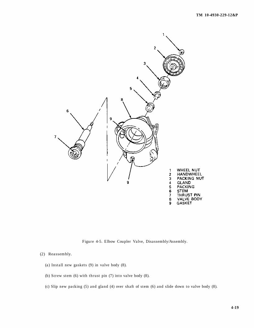
TM 10-4930-229-12&P
Figure 4-5. Elbow Coupler Valve, Disassembly/Assembly.
(2) Reassembly.
(a) Install new gaskets (9) in valve body (8).
(b) Screw stem (6) with thrust pin (7) into valve body (8).
(c) Slip new packing (5) and gland (4) over shaft of stem (6) and slide down to valve body (8).
4-19
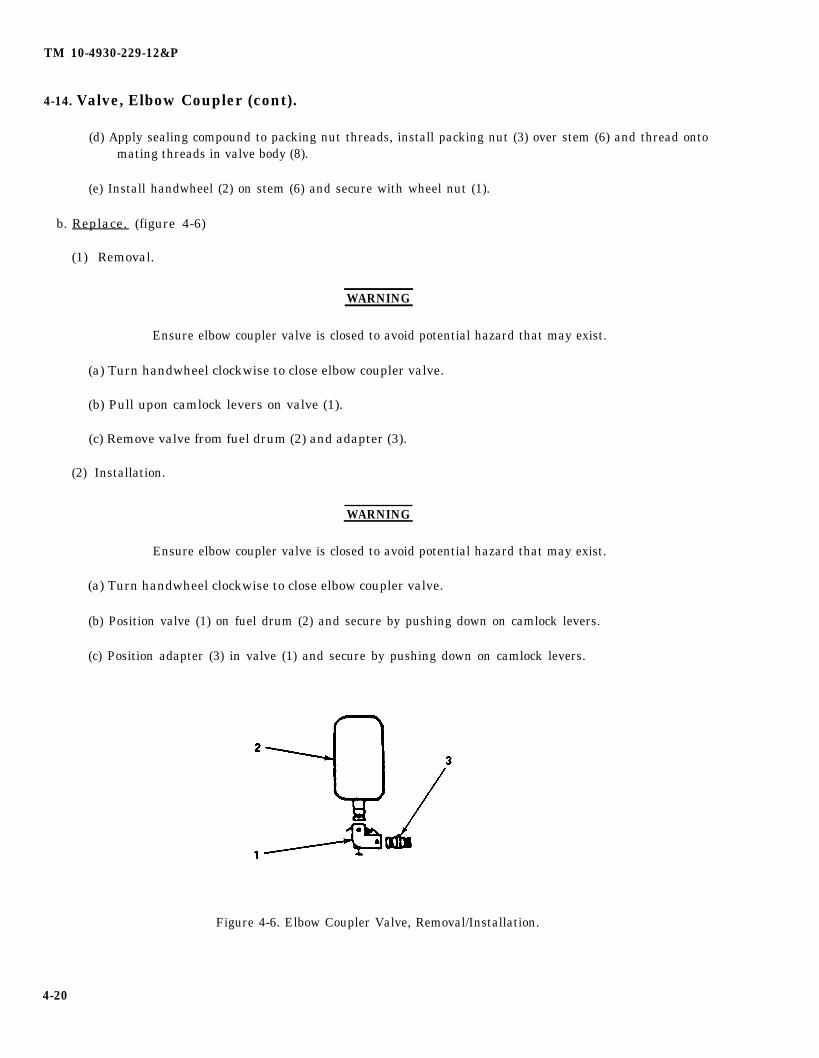
TM 10-4930-229-12&P
4-14. Valve, Elbow Coupler (cont).
(d) Apply sealing compound to packing nut threads, install packing nut (3) over stem (6) and thread ontomating threads in valve body (8).
(e) Install handwheel (2) on stem (6) and secure with wheel nut (1).
b. Replace. (figure 4-6)
(1) Removal.
WARNING
Ensure elbow coupler valve is closed to avoid potential hazard that may exist.
(a) Turn handwheel clockwise to close elbow coupler valve.
(b) Pull upon camlock levers on valve (1).
(c) Remove valve from fuel drum (2) and adapter (3).
(2) Installation.
WARNING
Ensure elbow coupler valve is closed to avoid potential hazard that may exist.
(a) Turn handwheel clockwise to close elbow coupler valve.
(b) Position valve (1) on fuel drum (2) and secure by pushing down on camlock levers.
(c) Position adapter (3) in valve (1) and secure by pushing down on camlock levers.
Figure 4-6. Elbow Coupler Valve, Removal/Installation.
4-20

TM 10-4930-229-12&P
4-15. Tee Fitting Assembly.
This task covers: a. Repair b. Replace
INITIAL SETUP
Tools:
Tool Kit, General Mechanic’s, Item 1, Section IIIAppendix B
Materials/Parts:
General Safety Instructions:
WARNING
Cleaning Solvent, Item 4, Appendix ERags, Wiping, Item 5, Appendix ESealing Compound, Item 3, Appendix EGasket
Equipment Conditions:
FARE shutdown, para 2-12.Inspected, para. 3-7
. Do not smoke or use an open flame in thevicinity of the FARE, failure to comply mayresult in personnel injury.
. Drain any fuel into suitable container. Clean upany fuel spills to prevent fire or environmentalhazard.
WARNING
Cleaning solvent, Federal Specification PD-660, is toxic and flammable.Use only in a well-ventilated area. Avoid prolonged breathing of fumes.Keep solvent away from flames. Do not use in excessive amounts.Avoid skin contact.
(b) Clean tee assembly with solvent and allow to dry.
(c) Remove two dust plugs (1) and dust cap (2).
(d) Remove gaskets (3). Discard gaskets.
(e) Remove female coupling halves (4) and male coupling half (5) from tee (6). Remove sealingcompound from threads.
(f) Inspect tee assembly for damaged dust plugs or dust cap.
(g) Inspect tee assembly for damaged camlock levers.
(h) Replace any parts found to be defective with new parts from stock.
a. Repair. (figure 4-7)
(1) Disassembly.
(a) Inspect tee fitting assembly for damaged or missing components.
4-21
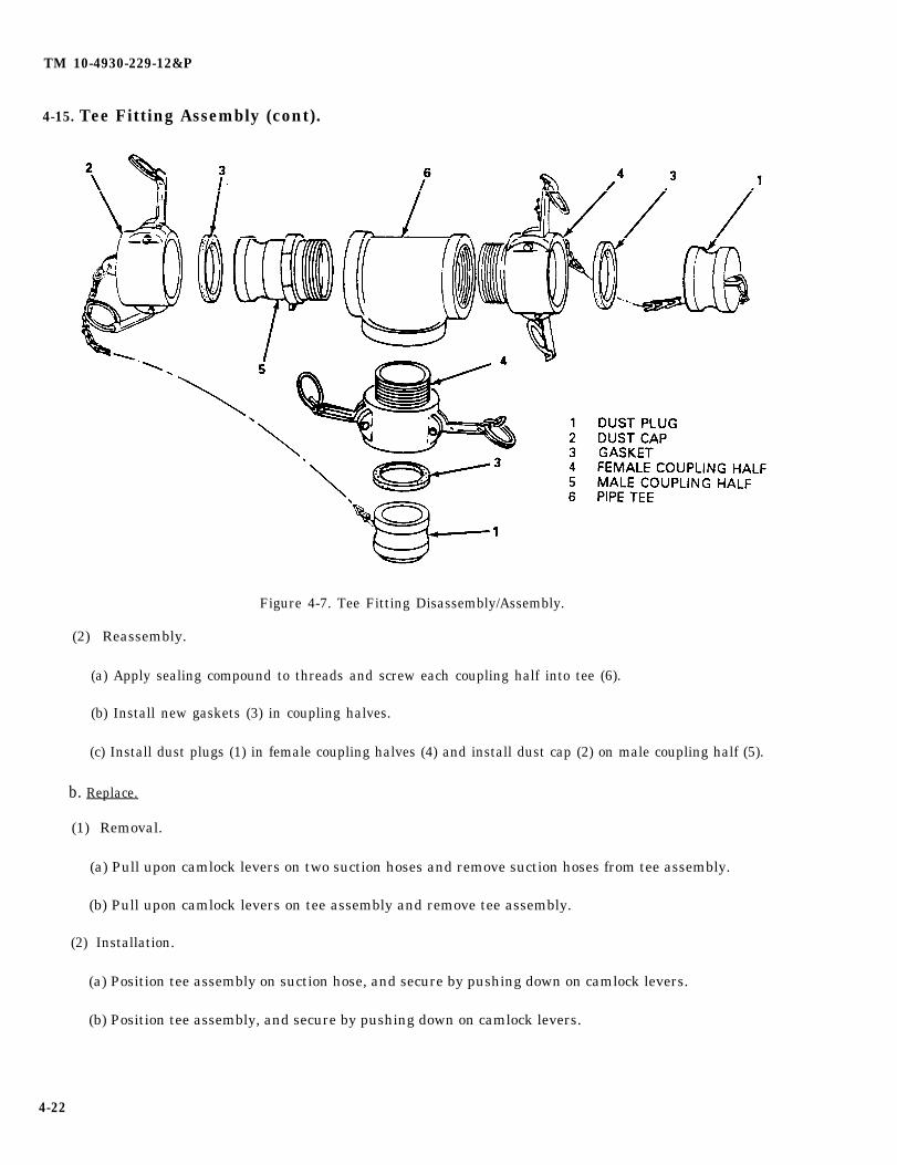
TM 10-4930-229-12&P
4-15. Tee Fitting Assembly (cont).
Figure 4-7. Tee Fitting Disassembly/Assembly.
(2) Reassembly.
(a) Apply sealing compound to threads and screw each coupling half into tee (6).
(b) Install new gaskets (3) in coupling halves.
(c) Install dust plugs (1) in female coupling halves (4) and install dust cap (2) on male coupling half (5).
b. Replace.
(1) Removal.
(a) Pull upon camlock levers on two suction hoses and remove suction hoses from tee assembly.
(b) Pull upon camlock levers on tee assembly and remove tee assembly.
(2) Installation.
(a) Position tee assembly on suction hose, and secure by pushing down on camlock levers.
(b) Position tee assembly, and secure by pushing down on camlock levers.
4-22
TM 10-4930-229-12&P
4-16. Adapter Assembly.
This task covers: a. Repair b. Replace
INITIAL SETUP
Tools: General Safety instructions:
Tool Kit, General Mechanic’s, Item 1, Section Ill,Appendix B
●
Materials/Parts:
Cleaning Solvent, Item 4, Appendix ERags, Wiping, Item 5, Appendix E ●
Gasket, P/N MS27030-6 (2 in.), Appendix FGasket, P/N MS27030-8 (3 in.), Appendix FGasket, P/N MS27030-9 (4 in.), Appendix F
Equipment Conditions:
FARE shutdown, para 2-12.
WARNING
Do not smoke or use an open flame in thevicinity of the FARE, failure to comply mayresult in personnel injury.
Drain any fuel into suitable container. Clean upany fuel spills to prevent fire or environmentalhazard.
a. Repair. (figure 4-8)
(1) Disassembly.
(a) Inspect adapter assembly for leaks, damaged or missing components.
WARNING
Cleaning solvent, Federal Specification PD-680, is toxic and flammable.Use only in a well-ventilated area. Avoid prolonged breathing of fumes.Keep solvent away from flames. Do not use in excessive amounts.Avoid skin contact.
(b) Clean adapter assembly with cleaning solvent and allow to dry.
(c) Disconnect hook (1) and remove dust plug (2) and gasket (3). Discard gasket.
(d) Disconnect hook (4). Remove dust cap (5) and gasket (6) from reducer (7). Discard gasket.
(2) Assembly.
(a) Install new gasket (6) and dust cap (5).
(b) Install new gasket (3) and dust plug (2).
(c) Connect hooks (1) and (4) to camlock levers on reducer (7).
4-23

TM 10-4930-229-12&P
4-16. Adapter Assembly (cont).
Figure 4-8. Adapter Assembly, Disassembly/Assembly.
b. Replace. (figure 4-9)
(1) Removal.
(a) Pull upon suction hose assembly (1) camlock levers and remove suction hose.
(b) Pull upon adapter camlock levers and remove adapter assembly (2) from fuel source.
(2) Installation.
(a) Position adapter assembly (2) on fuel source and secure by pushing down on camlock levers.
(b) Install suction hose assembly (1) and secure by pushing down on camlock levers.
Figure 4-9. Adapter Assembly, Removal/Installation.
4-24
TM 10-4930-229-12&P
4-17. Adapter, Nozzle.
This task covers: a. Repair b. Replace
INITIAL SETUP
Tools: General Safety Instructions:
None
Materials/Parts: ●
Cleaning Solvent, Item 4, Appendix ERags, Wiping, Item 5, Appendix E
●
Equipment Conditions:
FARE shutdown, para 2-12.
WARNING
Do not smoke or use an open flame in the vicin-ity of the FARE, failure to comply may result inpersonnel injury.
Drain any fuel into suitable container. Clean upany fuel spills to prevent fire or environmentalhazard.
a. Repair.
(1) Inspect nozzle adapter for leaks, ease of operation and missing or damaged components.
WARNING
Cleaning solvent, Federal Specification PD-680, is toxic and flammable. Use only ina well-ventilated area. Avoid prolonged breathing of fumes. Keep solvent awayfrom flames. Do not use in excessive amounts. Avoid skin contact.
(2) Clean adapter with cleaning solvent and allow to dry.
(3) Repair is limited to replacement of complete assembly.
b. Replace. (figure 4-10)
(1) Removal.
(a) Slide release sleeve (1) on closed circuit nozzle (2) and remove adapter (3).
(b) Install dust cap (4) on closed circuit refueling nozzle (2), and dust cap (5) on adapter.
(2) Installation.
(a) Remove dust cap (4) from closed circuit refueling nozzle and dust cap (5) from adapter.
(b) Slide release sleeve (1) on closed circuit nozzle (2) and install adapter (3).
4-25
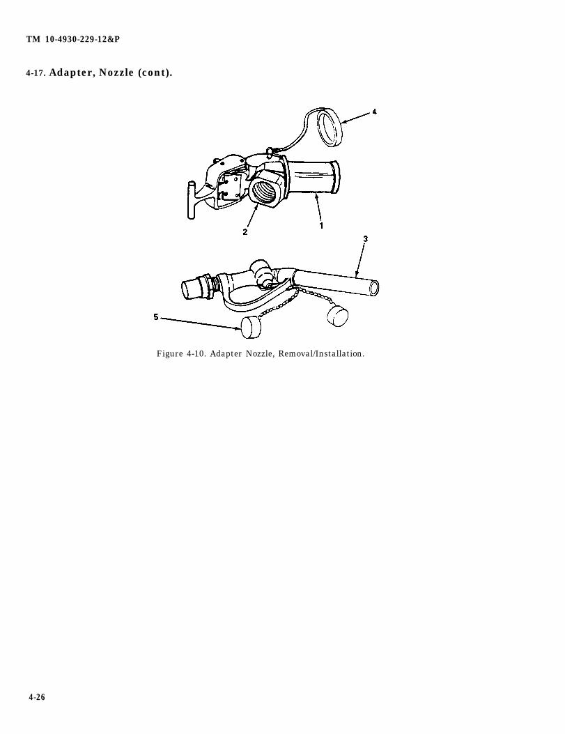
TM 10-4930-229-12&P
4-17. Adapter, Nozzle (cont).
Figure 4-10. Adapter Nozzle, Removal/Installation.
4-26
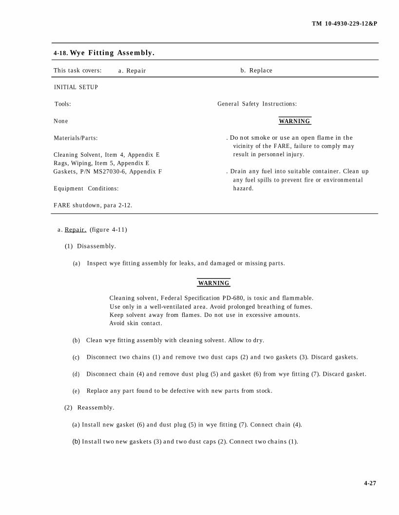
TM 10-4930-229-12&P
4-18. Wye Fitting Assembly.
This task covers: a. Repair b. Replace
INITIAL SETUP
Tools: General Safety Instructions:
None
Materials/Parts:
Cleaning Solvent, Item 4, Appendix ERags, Wiping, Item 5, Appendix EGaskets, P/N MS27030-6, Appendix F
Equipment Conditions:
FARE shutdown, para 2-12.
WARNING
. Do not smoke or use an open flame in thevicinity of the FARE, failure to comply mayresult in personnel injury.
. Drain any fuel into suitable container. Clean upany fuel spills to prevent fire or environmentalhazard.
a. Repair. (figure 4-11)
(1) Disassembly.
(a)
(b)
(c)
(d)
(e)
Inspect wye fitting assembly for leaks, and damaged or missing parts.
WARNING
Cleaning solvent, Federal Specification PD-680, is toxic and flammable.Use only in a well-ventilated area. Avoid prolonged breathing of fumes.Keep solvent away from flames. Do not use in excessive amounts.Avoid skin contact.
Clean wye fitting assembly with cleaning solvent. Allow to dry.
Disconnect two chains (1) and remove two dust caps (2) and two gaskets (3). Discard gaskets.
Disconnect chain (4) and remove dust plug (5) and gasket (6) from wye fitting (7). Discard gasket.
Replace any part found to be defective with new parts from stock.
(2) Reassembly.
(a) Install new gasket (6) and dust plug (5) in wye fitting (7). Connect chain (4).
(b) Install two new gaskets (3) and two dust caps (2). Connect two chains (1).
4-27
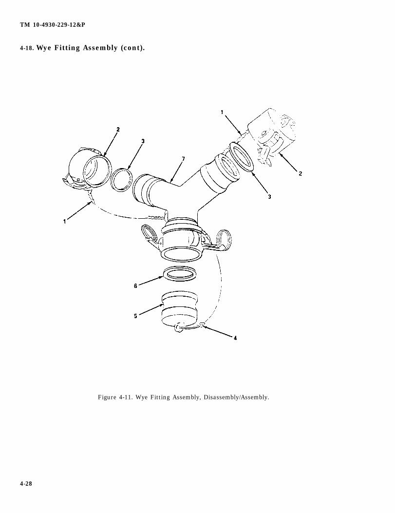
TM 10-4930-229-12&P
4-18. Wye Fitting Assembly (cont).
Figure 4-11. Wye Fitting Assembly, Disassembly/Assembly.
4-28
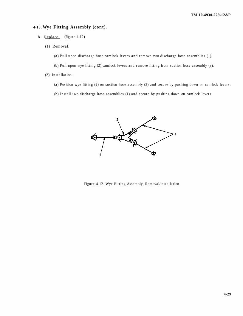
TM 10-4930-229-12&P
4-18. Wye Fitting Assembly (cont).
b. Replace. (figure 4-12)
(1) Removal.
(a) Pull upon discharge hose camlock levers and remove two discharge hose assemblies (1).
(b) Pull upon wye fitting (2) camlock levers and remove fitting from suction hose assembly (3).
(2) Installation.
(a) Position wye fitting (2) on suction hose assembly (3) and secure by pushing down on camlock levers.
(b) Install two discharge hose assemblies (1) and secure by pushing down on camlock levers.
Figure 4-12. Wye Fitting Assembly, Removal/installation.
4-29
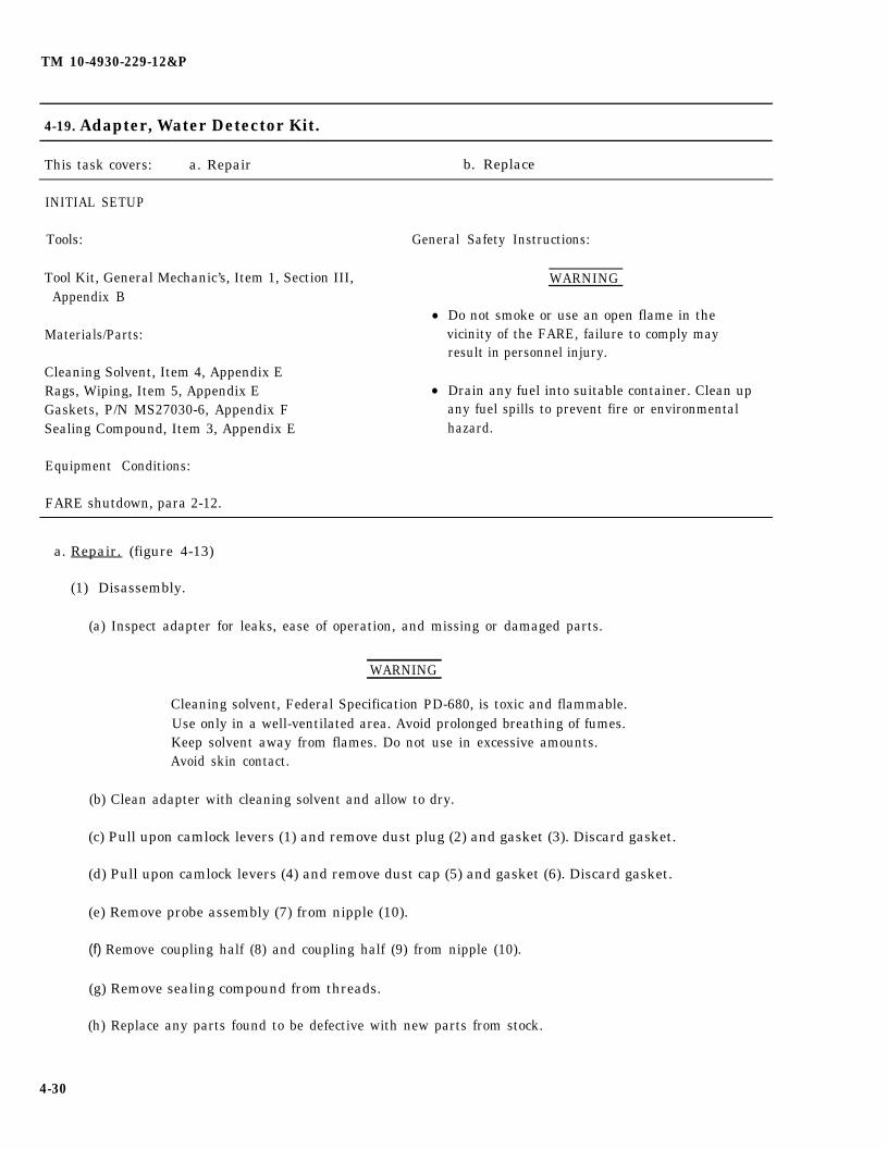
TM 10-4930-229-12&P
4-19. Adapter, Water Detector Kit.
This task covers: a. Repair b. Replace
INITIAL SETUP
Tools: General Safety Instructions:
Tool Kit, General Mechanic’s, Item 1, Section III,Appendix B
●
Materials/Parts:
Cleaning Solvent, Item 4, Appendix ERags, Wiping, Item 5, Appendix E ●
Gaskets, P/N MS27030-6, Appendix FSealing Compound, Item 3, Appendix E
Equipment Conditions:
FARE shutdown, para 2-12.
WARNING
Do not smoke or use an open flame in thevicinity of the FARE, failure to comply mayresult in personnel injury.
Drain any fuel into suitable container. Clean upany fuel spills to prevent fire or environmentalhazard.
a. Repair. (figure 4-13)
(1) Disassembly.
(a) Inspect adapter for leaks, ease of operation, and missing or damaged parts.
WARNING
Cleaning solvent, Federal Specification PD-680, is toxic and flammable.Use only in a well-ventilated area. Avoid prolonged breathing of fumes.Keep solvent away from flames. Do not use in excessive amounts.Avoid skin contact.
(b) Clean adapter with cleaning solvent and allow to dry.
(c) Pull upon camlock levers (1) and remove dust plug (2) and gasket (3). Discard gasket.
(d) Pull upon camlock levers (4) and remove dust cap (5) and gasket (6). Discard gasket.
(e) Remove probe assembly (7) from nipple (10).
(f) Remove coupling half (8) and coupling half (9) from nipple (10).
(g) Remove sealing compound from threads.
(h) Replace any parts found to be defective with new parts from stock.
4-30
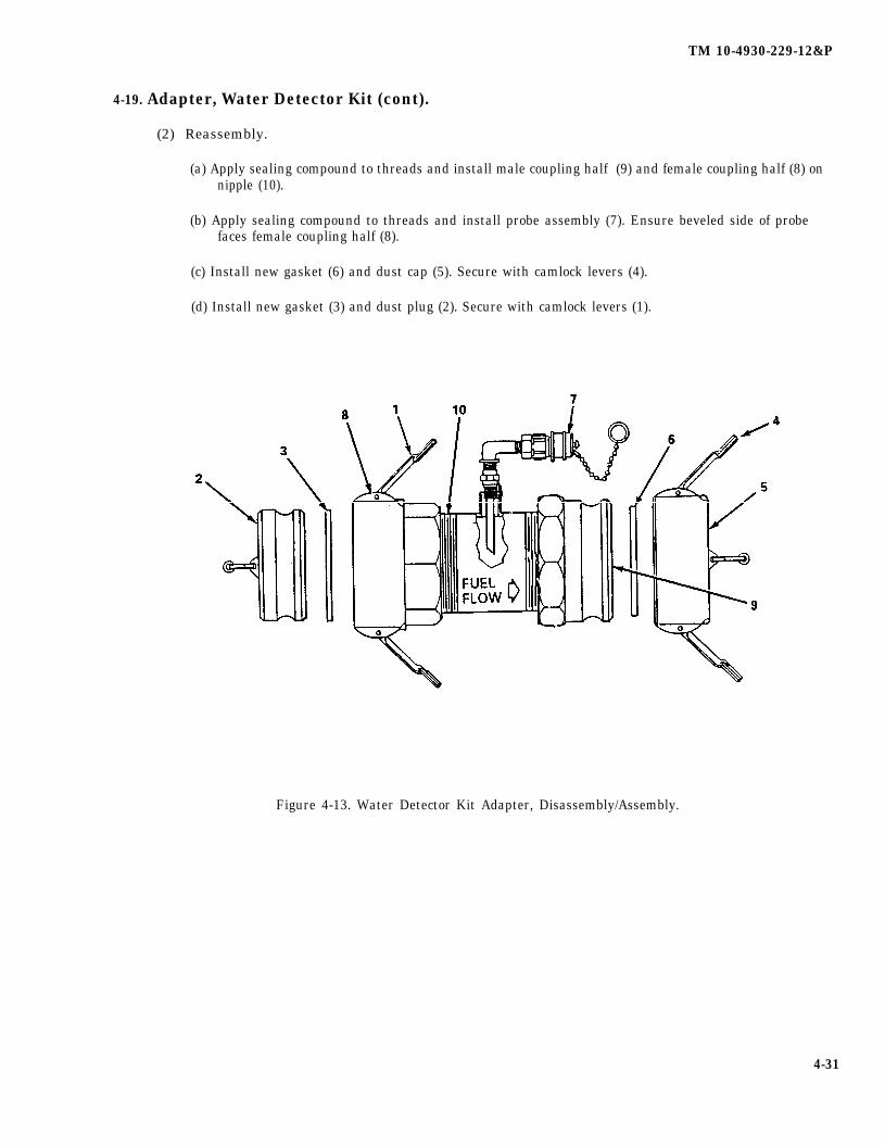
TM 10-4930-229-12&P
4-19. Adapter, Water Detector Kit (cont).
(2) Reassembly.
(a) Apply sealing compound to threads and install male coupling half (9) and female coupling half (8) onnipple (10).
(b) Apply sealing compound to threads and install probe assembly (7). Ensure beveled side of probefaces female coupling half (8).
(c) Install new gasket (6) and dust cap (5). Secure with camlock levers (4).
(d) Install new gasket (3) and dust plug (2). Secure with camlock levers (1).
Figure 4-13. Water Detector Kit Adapter, Disassembly/Assembly.
4-31

TM 10-4930-229-12&P
4-19. Adapter, Water Detector Kit (cont)
b. Replace. (figure 4-14)
(1) Removal.
(a) Pull upon suction hose camlock levers and remove hose assembly (1).
(b) Pull upon adapter camlock levers and remove adapter (2) from filter/separator (3).
(2) Installation.
(a) Pull upon camlock levers and remove dust plug and dust cap.
(b) Position adapter (2) on filter/separator (3) outlet fitting. Secure by pushing down on camlock levers.
(c) Install suction hose (1) and secure by pushing down on camlock levers.
Figure 4-14. Water Detector Kit Adapter, Removal/Installation.
4-32

TM 10-4930-229-12&P
4-20. Frame Assembly.
This task covers: a. Repair b. Replace
INITIAL SETUP
Tools:
Tool Kit, General Mechanic’s, Item 1, Section Ill,Appendix B
Equipment Conditions:
FARE shutdown, para. 2-12
General Safety Instructions:
WARNING
. Do not smoke or use an open flame in thevicinity of the FARE, failure to comply mayresult in personnel injury.
. Drain any fuel into suitable container. Clean upany fuel spills to prevent fire or environmentalhazard.
a. Repair. (figure 4-15)
(1)
(2)
(3)
(4)
(5)
Inspect frame for crack, damaged or missing parts.
WARNING
Cleaning solvent, Federal Specification PD-680, is toxic and flammable.well-ventilated area. Avoid prolonged breathing of fumes. Keep solventflames. Do not use in excessive amounts. Avoid skin contact.
NOTE
Do not apply solvent to container.
Clean frame with cleaning solvent, allow to dry.
Use only in aaway from
If container (2) is damaged, remove twenty-eight screws (3), fourteen loops (4) and remove container(2). Position new container (2) on frame (1) and secure with fourteen loops (4) and twenty-eightscrews (3).
If any straps (5 or 6) are damaged, remove two screws (3) and one loop (4) per strap.damaged strap(s). Position new strap(s) (5 or 6) on frame (1) and secure with loop (4)(3) per strap.
Repair frame (1) by straightening or painting frame. Refer to TM 43-0139 for painting.
Removeand two screws
b. Replace. (figure 4-15)
(1) Removal.
(a) Remove discharge hoses from frame (1).
4-33
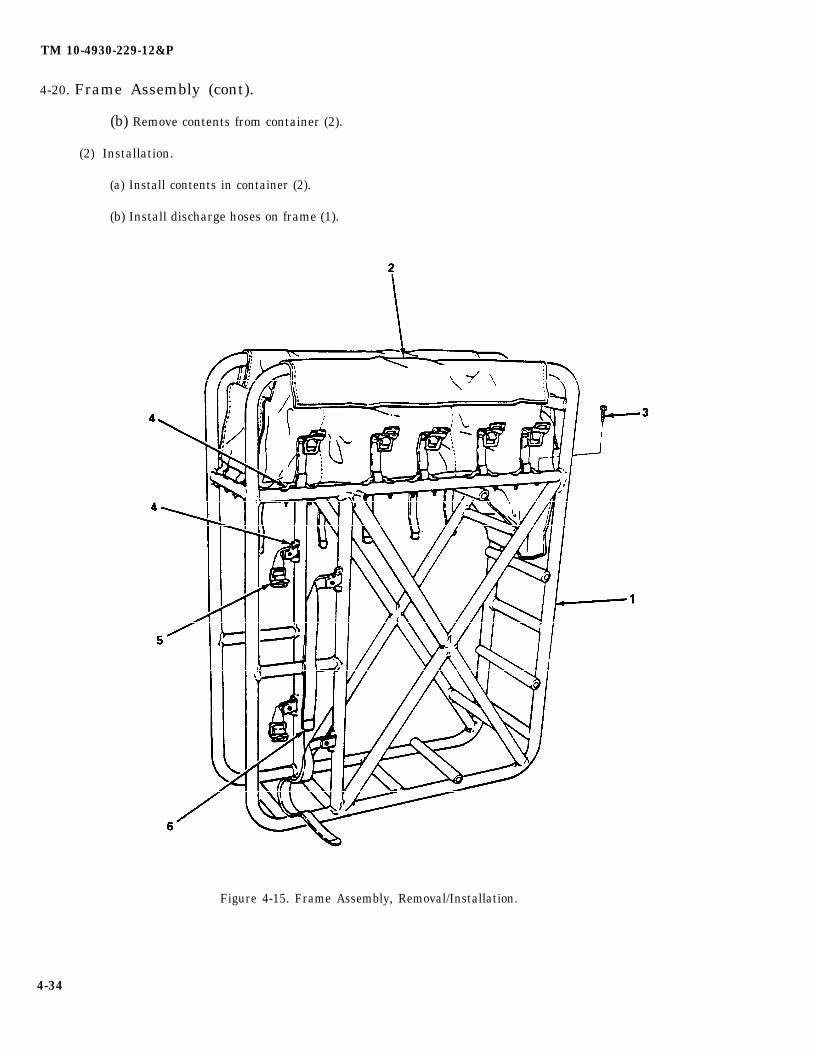
TM 10-4930-229-12&P
4-20. Frame Assembly (cont).
(b) Remove contents from container (2).
(2) Installation.
(a) Install contents in container (2).
(b) Install discharge hoses on frame (1).
Figure 4-15. Frame Assembly, Removal/Installation.
4-34
TM 10-4930-229-12&P
Section VI. PREPARATION FOR SHIPMENT OR STORAGE
Paragraph Page
4-21 General . . . . . . . . . . . . . . . . . . . . . . . . . . . . . . . . . . . . . . . . . . . . . . . . . . . . . . . . . . . . ...4-354-22 Administrative Storage . . . . . . . . . . . . . . . . . . . . . . . . . . . . . . . . . . . . . . . . . . . . . . . . . ...4-35
4-21. General. This section describes administrative storage procedures and the preparation for shipment orshort term/intermediate term storage of components of the FARE. Procedures for short term and intermediateterm storage are identical.
4-22. Administrative Storage.
a. Placement of Equipment in Admistrative Storage. Placement of equipment in administrative storageshould be for short periods of time when a shortage of maintenance effort exists. Items should be in missionreadiness within 24 hours or within the time factors as determined by the directing authority. During the storageperiod, appropriate maintenance records will be kept.
b. Before Placing Equipment in Administrative Storage. Before placing equipment in administrative storage,current maintenance services and equipment serviceable criteria (ESC) evaluations should be completed,shortcomings and deficiencies should be corrected, and all modification work orders (MWO’s) should be applied.
c. Storage Site Selection. Inside storage is preferred for items selected for administrative storage. If insidestorage is not available, trucks, vans, conex containers and other containers may be used.
d. Storage Tanks. The storage tank shall be dusted with talc or other anti-sticking compound to preventadhesion to itsetf. Permanently attached fittings shall be cushioned with material conforming to PPP-C-795, orequivalent, and secured in place with tape conforming to PPP-T-97. Tank shall be packed in a PPP-B-601overseas style optional wood box, or equivalent, as applicable to the weight of the complete tank. The box shallbe loosely lined with polyethylene material conforming to L-P-378, Type l, Class 1, having a minimum thickness of.006 inch to prevent abrasion. The tank shall be cushioned, blocked and braced as needed for safe shipment todestination.
e. Pump/Engine Assembly and Hose Kits. Interior surfaces of the pump engine assembly shall be coated withlubricating oil conforming to MIL-L-21260, Grade 30, with excess of oil drained. Draincock shall be left open. Inletand outlet shall have dust caps and plugs installed. Exterior surfaces, when required, shall have P-1 typepreservative applied. All internal engine components shall be preserved with oil conforming to Grade 10,30, or50, as applicable, in MIL-L-21260. All openings into the engine shall be sealed with plastic caps, plugs or tape.The pump/engine assembly and hose kits shall be prepared for mobile shipment. A plywood housing shall beplaced over the components. Block and brace as needed for safe shipment. The housing shall be secured inplace by the use of lumber dunnage, using strapping as required for safe shipment to destination.
f. Filter/separator. The filter-separator with canisters and filter elements shall not require preservation;however, the water drain valve shall be opened with dust plug and cap installed. Each filter-separator shall bepacked in a box conforming to PPP-B-601 overseas, Style A or B. Blocking and bracing to prevent movement ofcontents shall be accomplished as needed for safe shipment to destination.
g. Other Components. All other components not addressed in d. through f., above, shall be packed withcushioning, blocking and bracing, as necessary, in an overseas wood box, style optional, conforming toPPP-B-601.
4-35/(4-36 blank)

TM 10-4930 229-12&P
APPENDIX A
REFERENCES
A-1. Scope. This appendix lists all forms, technical manuals, and miscellaneous publications referenced in thismanual.
A-2. Publication Indexes. The following publication indexes should be consulted frequently for the latestchanges or revisions of references given in this appendix and for new publications relating to the material covered inthis manual:
Consolidated Index of Army Publications and Blank Forms . . . . . . . . . . . . . . . . . . . . . . . . . . . . . DA PAM 25-30The Army Maintenance Management System (TAMMS). . . . . . . . . . . . . . . . . . . . . . . . . . . . . . . . DA PAM 738-750
A-3. Technical Manuals.
Painting instructions for Field Use... . . . . . . . . . . . . . . . . . . . . . . . . . . . . . . . . . . . . . . . . . . .. TM 43-0139
Engine, Gasoline, 3 HP, Military Standard. . . . . . . . . . . . . . . . . . . . . . . . . . . . . . . . . . . . . . . . . . .. TM 9-2805-257-14
Pump Assembly, Flammable Liquid, Centrifugal, 100 GPM, Frame Mounted . . . . . . . . . . . . . . TM 10-4320-256-14&P
Filter/Separator, Liquid Fuel, Optimum Performance, Lightweight,100 GPM, Frame Mounted . . . . . . . . . . . . . . . . . . . . . . . . . . . . . . . . . . . . . . . . . . . . . . . . TM 5-4330-217-12&P
Nozzle Assembly, Closed-Circuit Refueling with Strainer Assembly. . . . . . . . . . . . . . . . . . . . . . TM 5-4930-226-12&P
Closed Circuit Refueling Nozzle . . . . . . . . . . . . . . . . . . . . . . . . . . . . . . . . . . . . . . . . . . . . . . . . . . .. TM 5-4930-234-13&P
Closed Circuit Refueling Nozzle Assembly . . . . . . . . . . . . . . . . . . . . . . . . . . . . . . . . . . . . . . . . . .. TM 5-4930-235-13&P
Drum, Fabric, Collapsible, Non-Vented, 500-Gallon Liquid Fuel; 250 Gallon,Portable Water and 55-Gallon, Portable Water . . . . . . . . . . . . . . . . . . . . . . . . . . . . . . . . . . . . . . TM 10-8110-201-14&P
Administrative Storage of Equipment. . . . . . . . . . . . . . . . . . . . . . . . . . . . . . . . . . . . . . . . . . . . . . .. TM 740-90-1
Procedure for Destruction of Equipment to Prevent Enemy Use . . . . . . . . . . . . . . . . . . . . . . . . . TM 750-244-3
Preservation, Packaging, Packing of Military Supplies and Equipment(Vols. 1 and 2) . . . . . . . . . . . . . . . . . . . . . . . . . . . . . . . . . . . . . . . . . . . . . . . . . . . . . . . . . . . . . . . . . TM 38-230-1 and
TM 38-230-2
A-4. Field Manuals.
General Fabric Repair . . . . . . . . . . . . . . . . . . . . . . . . . . . . . . . . . . . . . . . . . . . . . . . . . . . . TM 10-16First Aid for Soldiers . . . . . . . . . . . . . . . . . . . . . . . . . . . . . . . . . . . . . . . . . ... . . . . . FM 21-11
A-1

TM 10-4930-229-12&P
A-5. Lubricants and Lubrication Orders (LO).
Fuels, Lubricants, Oil and Waxes... . . . . . . . . . . . . . . . . . . . . . . . . . . . . . . . . . . . . . . . . . . . . . . .. C9100-IL
Engine, Gasoline, 3HP, Military Standard . . . . . . . . . . . . . . . . . . . . . . . . . . . . . . . . . . . . . . . . . . .. LO 9-2805-257-12
A-6. Technical Bulletins.
Hand Portable Fire Extinguishers Approved for Army Users . . . . . . . . . . . . . . . . . . . . . . . . . . . . TB 5-4200-200-10
Preservation of USAMEC Mechanical Equipment for Shipment and Storage. . . . . . . . . . . . . . . TB 740-97-2
A-7. Army Regulations.
Dictionary of United States, Army Terms . . . . . . . . . . . . . . . . . . . . . . . . . . . . . . . . . . . . . . . . . . . .. AR 310-25
Authorized Abbreviations and Brevity Codes . . . . . . . . . . . . . . . . . . . . . . . . . . . . . . . . . . . . . . . .. AR 310-50
Army Materiel Maintenance Concepts and Policies . . . . . . . . . . . . . . . . . . . . . . . . . . . . . . . . . . .. AR 750-1
Packaging of Material . . . . . . . . . . . . . . . . . . . . . . . . . . . . . . . . . . . . . . . . . . . . . . . . . . . . . . . . . . . AR 700-15
A-8. Forms.
Recommended Changes to Publications and Blank Forms . . . . . . . . . . . . . . . . . . . . . . . . . . . . . . DA Form 2028
The Army Maintenance Management System (TAMMS) . . . . . . . . . . . . . . . . . . . . . . . . . . . . . . . . DA Form 738-750
Product Quality Deficiency Report . . . . . . . . . . . . . . . . . . . . . . . . . . . . . . . . . . . . . . . . . . . . . . . . .. SF-368
Equipment inspection and Maintenance Worksheet . . . . . . . . . . . . . . . . . . . . . . . . . . . . . . . . . . . DA Form 2404
A-2
TM 10-4930-229-12&P
APPENDIX B
MAINTENANCE ALLOCATION CHART
Section I. INTRODUCTION
B-1. Maintenance Allocation Chart (MAC). This MAC assigns maintenance functions in accordancewith the Three Level Maintenance Concept.
B-2. Use of the Maintenance Allocation Chart, Section II
a. The MAC assigns maintenance functions based on the following considerations:
(1) Skills available.
(2) Work time required.
(3) Tools and test equipment required and/or available.
b. If a lower level of maintenance identified in column (4) of the MAC cannot perform all tasks of a singlemaintenance function (e.g., test, repair), then the higher level that can perform other tasks of that function is alsoindicated.
c. Higher maintenance levels are automatically authorized to perform maintenance functions assigned to alower maintenance level.
d. Higher maintenance levels will perform the maintenance functions of lower maintenance levels whenrequired or directed by the Commander who has authority to direct such tasking.
e. Assignment of a maintenance function in the MAC does not carry automatic authorization to carry therelated spare or repair parts in stock. Information to requisition or secure parts will be as specified in theassociated Repair Parts and Special Tools List (RPSTL).
f. Normally, there is no deviation from the assigned level of maintenance. However, in cases of operationalnecessity, maintenance functions assigned to a higher level may be assigned to a lower level on a one-time basis,with authorization from the higher level maintenance officer. Transfer of a function to a lower level does notrelieve the higher level of responsibility. The higher level will provide technical supervision and inspection of thefunction being performed.
B-3. Maintenance Functions. Maintenance functions will be limited to and defined as follows:
a. Inspect. To determine the serviceability of an item by comparing its physical, mechanical, and/or electricalcharacteristics with established standards through examination (e.g., by sight, sound, or feel).
b. Test. To verify serviceability and detect incipient failure by measuring the mechanical or electricalcharacteristics of an item and comparing those characteristics with prescribed standards.
B-1
TM 10-4930-229-12&P
c. Service. Operations required periodically to keep an item in proper operating condition, i.e., to clean(includes decontaminate), to preserve, to drain, or to replenish fuel, lubricants, hydraulic fluids, or compressed airsupplies.
d. Adjust. To maintain within Prescribed limits, by bringing into proper or exact position, or by setting theoperating characteristics to the specified parameters.
e. Aline. To adjust specified variable elements of an item to bring about optimum or desired performance.
f. Calibrate. To determine and cause corrections to be made or to be adjusted on instruments or testmeasuring and diagnostic equipment used in precision measurement. Consists of comparison of two instruments,one of which is a certified standard of known accuracy, to detect and adjust any discrepancy in the accuracy of theinstrument being compared.
g. Install. The act of emplacing, seating, or fixing into position an item, part, or module (component assembly)in a manner to allow the proper functioning of an equipment or system.
h. Replace. The act of substituting a serviceable like type part, a subassembly, or module (component orassembly) for an unserviceable counterpart.
i. Repair. The application of maintenance services (inspect, test, service, adjust, aline, calibrate, or replace)or other maintenance actions (welding, grinding, riveting, straightening, facing, remachining, or resurfacing) torestore serviceability to an item by correcting specific damage, fault, malfunction, or failure in a part, subassembly,module (component or assembly), end item, or system.
j. Overhaul. That maintenance effort (service/action) necessary to restore an item to a completelyserviceable operational condition as prescribed by maintenance standards in appropriate technical publications(i.e., DMWR). Overhaul does not normally return an item to a like new condition.
k. Rebuild. Consists of those services/actions necessary for the restoration of unserviceable equipment to alike new condition in accordance with original manufacturing standards. Rebuild is the highest degree of materielmaintenance applied to Army equipment. The rebuild operation includes the act of returning to zero those agemeasurements (hours/miles, etc.) considered in classifying Army equipment/components.
B-4. Explanation of Columns in the MAC, Section II.
a. Column (1). Group Number. Column 1 lists functional group code numbers which are assigned to identifymaintenance significant components, assemblies, subassemblies, and modules to their next higher assembly.
b. Column (2). Component/Assembly. Column 2 contains the item names of components, assemblies,subassemblies, and modules for which group numbers (column 1 ) are assigned and for which maintenance isauthorized.
c. Column (3). Maintenance Function. Column 3 lists the functions to be performed on items listed in Column2. (Function definitions are contained in paragraph B-3.)
B-2

TM 10-4930-229-12&P
d. Column (4). Maintenance Level. The maintenance levels, Unit, Intermediate, and Depot, are allottedseparate subcolumns within column 4. Entry of a work time figure (such as 1.0, 0.2) in a subcolumn indicates thatthat level is authorized to perform the function listed in column 3, and the average time required to do the functionis the work time figure. If the number or complexity of tasks within a maintenance function varies from onemaintenance level to another, the applicable work time figure for each level will be entered for that function. Thework time figure represents the average time it takes to restore a component/assembly to a serviceable conditionunder a typical field operating environment.
e. Column (5). Tools and Equipment. Column 5 specifies, by code, common tool sets (not individual toolsfrom those sets), common TMDE, and special tools, TMDE, and support equipment required to perform adesignated function. The code in Column 5 keys to the listing in Section III of the MAC.
f. Column (6). This column when applicable, contains a letter code which is keyed to anexplanation of the code contained in Section IV of the MAC.
B-5. Explanation of Columns in the MAC, Section III.
a. Column (1) . Tool or Test Equipment Reference Code. The tool or test equipment reference code correlateswith a code used in the MAC, Section II, Column 5.
b. Column (2), Maintenance Category. The lowest category of maintenance authorized to use the tool or testequipment.
c. Column (3).Nomenclature. Name or identification of the tool or test equipment.
d. Column (4) National/NATO Stock Number. The National stock number of the tool or test equipment,
e. Column (5). Tool Number. The manufacturer’s part number.
B-6. Explanation of Columns in the MAC, Section IV.
a. Column (1). Reference Code. The code recorded in column 6, Section II.
b. Column (2). Remarks. This column lists information pertinent to the maintenance function being performedas indicated in the MAC, Section II.
B-3
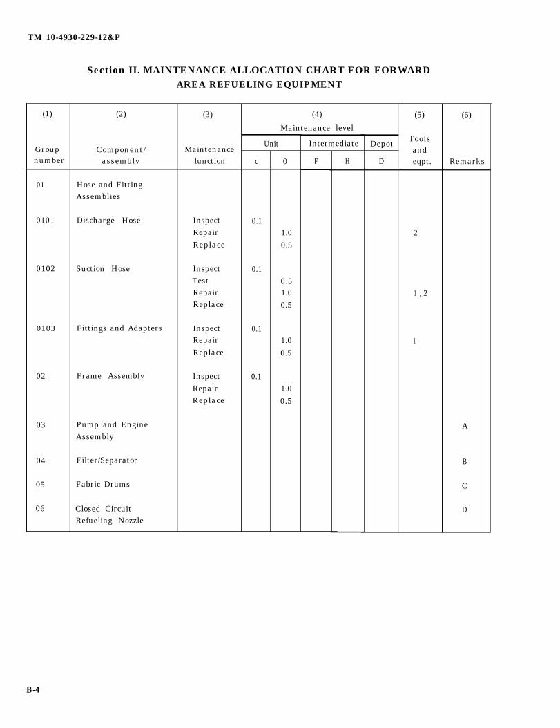
TM 10-4930-229-12&P
(1)
Groupnumber
01
0101
0102
0103
02
03
04
05
06
Section II. MAINTENANCE ALLOCATION CHART FOR FORWARDAREA REFUELING EQUIPMENT
(2)
Component/assembly
Hose and FittingAssemblies
Discharge Hose
Suction Hose
Fittings and Adapters
Frame Assembly
Pump and EngineAssembly
Filter/Separator
Fabric Drums
Closed CircuitRefueling Nozzle
(3)
Maintenancefunction
InspectRepairReplace
InspectTestRepairReplace
InspectRepairReplace
InspectRepairReplace
(4)
Maintenance level
Unit
c
0.1
0.1
0.1
0.1
0
1.0
0.5
0.51.00.5
1.0
0.5
1.00.5
Intermediate
F H
Depot
D
(5)
Toolsandeqpt.
2
, 21
1
(6)
Remarks
A
B
C
D
B-4

TM 10-4930-229-12&P
Section III. TOOLS AND TEST EQUIPMENT REQUIREMENTS FORFORWARD AREA REFUELING EQUIPMENT
Tool or testequipment Maintenance National NATO PN
ref code category Nomenclature stock number Tool number(1) (2) (3) (4) (5)
1 O Tool Set, General Mechanic’s 5180-00-177-7033
2 O Banding Tool 5120-00-278-9925
3 O Multimeter, Digital 6625-01-145-2430
B
C
D
Section IV. REMARKS
Reference code Remarks
A Refer to TM 10-4320 -256-14&P and TM 9-2805-257-14 for maintenance information onthe pump and engine assembly.
Refer to TM 5-4330-217-12&P for maintenance information on the filter/separator.
Refer to TM 10-8110-201-14&P for maintenance information on the fabric drum.
Refer to TM 5-4930 -226-12&P, TM 5-4930-234-13&P and TM 5-4930-235-13&P formaintenance information on the closed-circuit refueling nozzles.
B-5/(B-6 blank)

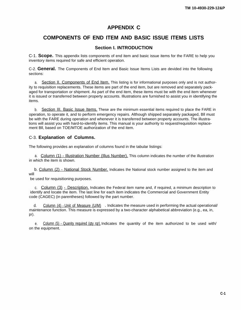
TM 10-4930-229-12&P
APPENDIX C
COMPONENTS OF END ITEM AND BASIC ISSUE ITEMS LISTS
Section I. INTRODUCTION
C-1. Scope. This appendix lists components of end item and basic issue items for the FARE to help youinventory items required for safe and efficient operation.
C-2. General. The Components of End Item and Basic Issue Items Lists are devided into the followingsections:
a. Section II. Components of End Item. This listing is for informational purposes only and is not author-ity to requisition replacements. These items are part of the end item, but are removed and separately pack-aged for transportation or shipment. As part of the end item, these items must be with the end item wheneverit is issued or transferred between property accounts. Illustrations are furnished to assist you in identifying theitems.
b. Section III. Basic Issue Items. These are the minimum essential items required to place the FARE inoperation, to operate it, and to perform emergency repairs. Although shipped separately packaged, Bll mustbe with the FARE during operation and whenever it is transferred between property accounts. The illustra-tions will assist you with hard-to-identify items. This manual is your authority to request/requisition replace-ment Bll, based on TOE/MTOE authorization of the end item.
C-3. Explanation of Columns.
The following provides an explanation of columns found in the tabular listings:
a. Column (1) - Illustration Number (Illus Number). This column indicates the number of the illustrationin which the item is shown.
b. Column (2) - National Stock Number. Indicates the National stock number assigned to the item andwillbe used for requisitioning purposes.
c. Column (3) - Description. Indicates the Federal item name and, if required, a minimum description toidentify and locate the item. The last line for each item indicates the Commercial and Government Entity
code (CAGEC) (in parentheses) followed by the part number.
d. Column (4) - Unit of Measure (U/M) . Indicates the measure used in performing the actual operational/maintenance function. This measure is expressed by a two-character alphabetical abbreviation (e.g., ea, in,pr).
e. Column (5) - Quanity required (qty rqr). Indicates the quantity of the item authorized to be used with/on the equipment.
C-1
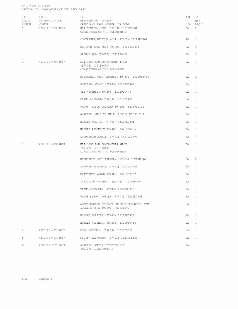
TM10-4930-229-12&PSECTION II. COMPONENTS OF END ITEM LIST
(1) (2) (3) (4) (5)ILLUS NATIONAL STOCK DESCRIPTION USABLE QTYNUMBER NUMBER CAGEC AND PART NUMBER ON CODE U/M REQ'D1 4930-00-513-9906 KIT,SUCTION HOSE (97403) 13219E0501 EA 2
CONSISTING OF THE FOLLOWING:
CONTAINER,SUCTION HOSE (97403) 13219E0461 EA 1
SUCTION HOSE ASSY (97403) 13219E0464 EA 6
GROUND ROD (97403) 13219E0462 EA 2
2 4930-00-475-3057 KIT,HOSE AND COMPONENTS (TEE) EA 1(97403) 13219E0503CONSISTING OF THE FOLLOWING:
DISCHARGE HOSE ASSEMBLY (97403) 13219E0465 EA 2
BUTTERLY VALVE (97403) 13219E0467 EA 1
TEE ASSEMBLY (97403) 13219E0476 EA 1
FRAME ASSEMBLY(97403) 13219E0470 EA 1
VALVE, ELBOW COUPLER (97403) 13219E0491 EA 1
ADAPTER, MALE TO MALE (96906) MS39352-9 EA 1
NOZZLE ADAPTER (97403) 13219E0498 EA 1
NOZZLE ASSEMBLY (97403) 13219E0486 EA 1
ADAPTER ASSEMBLY (97403) 13219E0493 EA 1
3 4930-00-483-3849 KIT,HOSE AND COMPONENTS (WYE) EA 1(97403) 13219E0504CONSISTING OF THE FOLLOWING:
DISCHARGE HOSE ASEMBLY (97403) 13219E0465 EA 2
ADAPTER ASSEMBLY (97403) 13219E0466 EA 1
BUTTERFLY VALVE (97403) 13219E0467 EA 1
Y-FITTING ASSEMBLY (97403) 13219E0475 EA 1
FRAME ASSEMBLY (97403) 13219E0470 EA 1
VALVE,ELBOW COUPLER (97403) 13219E0491 EA 1
ADAPTER,MALE BY MALE QUICK DISCONNECT, CAM EA 1LOCKING TYPE (96906) MS39352-2
NOZZLE ADAPTER (97403) 13219E0498 EA 1
NOZZLE ASSEMBLY (97403) 13219E0486 EA 1
4 4320-00-427-0002 PUMP ASSEMBLY (97403) 13219E5350 EA 1
5 4330-00-491-4957 FILTER SEPARATOR (97403) 13217E5350 EA 1
6 4930-01-017-3639 ADAPTER, WATER DETECTOR KIT EA 1(97403) 13220E9406-1
C-2 CHANGE 4

TM 10-4930-229-12&P
C-3

TM 10-4930-229-12&P
Section III. BASIC ISSUE ITEMS LIST
C-4 Change 3

TM 10-4930-229-12&P
APPENDIX DADDITIONAL AUTHORIZATION LIST
Section I. INTRODUCTION
D-1. Scope. This appendix lists additional items you are authorized for the support of the Forward Area RefuelingEquipment (FARE).
D-2. General. This list identifies items that do not have to accompany the equipment and that do have to be turnedin with it. These items are all authorized to you by CTA, MTOE, TDA, OR JTA.
D-3. Explanation of Listing. National stock numbers, descriptions, and quantities are provided to help you identifyand request the additional items you require to support this equipment.
Section II. ADDITIONAL AUTHORIZATION ITEMS LIST
(1)
NationalStock Number
6640-00-244-9478
8415-00-641-4601
4240-00-052-3776
4240-00-022-2946
(2)
Description UsableCAGEC and Part Number on Code
Test Kit, Fuel Contamination (32218)Model GTP 323 Series II
Gloves, Chemical and Oil Protective (81348)ZZ-G-381
Goggles, Industrial (58536)A-A-1110
Protector, Aural (40635)95635
(3)
U/M
EA
PR
PR
EA
(4)
QtyAuth
1
2
2
2
*U.S. GOVERNMENT PRINTING OFFICE: 1994 - 555-028/00099 Change 3 D-1 /(D-2 blank)

APPENDIX E
EXPENDABLE/DURABLE SUPPLIES
TM 10-4930-229-12&P
AND MATERIALS LIST
Section I. INTRODUCTION
E-1. Scope. This appendix lists expendable supplies and materials you need to operate and maintain theForward Area Refueling Equipment (FARE). These items are authorized to you by CTA 50-970, Expendable/Durable Items (Except Medical, Class V, Repair Parts, and Heraldic Items).
E-2. Explanation of Columns.
a. Column (1) - Item Number. This number is assigned to the entry in the listing and is referenced in thenarrative instructions to identify the material (e.g., “Use Sealing Compound, Item 5, App. E“).
b. Column (2) – Level. This column identifies the lowest level of maintenance that requires the listed item.(Enter as applicable).
C – Operator/CrewO – Unit MaintenanceF – Direct Support MaintenanceH - General Support MaintenanceD – Depot Maintenance
c. Column (3) - National Stock Number. This is the National stock number assigned to the item; use it torequest or requisition the item.
d. Column (4) - Description. Indicates the Federal item name, and, if required, a description to identify theitem.
e. Column (5) - Unit of Measure U/M). Indicates the measure used in performing the actual maintenancefunction. This measure is expressed by a two-character alphabetical abbreviation (e.g., ea, in, pr). If the unit ofmeasure differs from the unit of issue, requisition the lowest unit of issue that will satisfy your requirements.
E-1

TM10-4930-229-12&PSECTION II. EXPENDABLE/DURABLE SUPPLIES AND MATERIALS LIST(1) (2) (3) (4) (5)ITEM NATIONALNUMBER LEVEL STOCK NUMBER DESCRIPTION U/M1 O 5340-00-244-7325 SEALS,1/2 IN. STRAPPING EA
2 O 5340-00-245-9438 STRAPPING, 1/2 IN. RL
3 O 8030-00-543-4384 SEALING COMPOUND (81349) MIL-S-7916 TU
4 O 6850-00-664-5685 SOLVENT, CLEANING (81346) ASTM D 235 TY 1 QT
5 O 7920-00-205-1711 RAGS, WIPING (58536) A-A531 LB
E-2
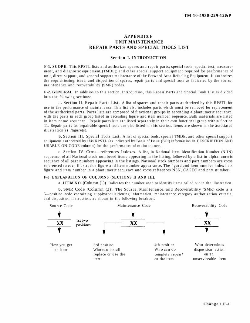
TM 10-4930-229-12&P
APPENDIX FUNIT MAINTENANCE
REPAIR PARTS AND SPECIAL TOOLS LIST
Section I. INTRODUCTION
F-1. SCOPE. This RPSTL lists and authorizes spares and repair parts; special tools; special test, measure-ment, and diagnostic equipment (TMDE); and other special support equipment required for performance ofunit, direct support, and general support maintenance of the Forward Area Refueling Equipment. It authorizesthe requisitioning, issue, and disposition of spares, repair parts and special tools as indicated by the source,maintenance and recoverability (SMR) codes.
F-2. GENERAL. In addition to this section, Introduction, this Repair Parts and Special Tools List is dividedinto the following sections:
a. Section II. Repair Parts List. A list of spares and repair parts authorized by this RPSTL foruse in the performance of maintenance. This list also includes parts which must be removed for replacementof the authorized parts. Parts lists are composed of functional groups in ascending alphanumeric sequence,with the parts in each group listed in ascending figure and item number sequence. Bulk materials are listedin item name sequence. Repair parts kits are listed separately in their own functional group within Section11. Repair parts for repairable special tools are also listed in this section. Items are shown in the associatedillustration(s) /figure(s).
b. Section III. Special Tools List. A list of special tools, special TMDE, and other special supportequipment authorized by this RPSTL (as indicated by Basis of Issue (BOl) information in DESCRIPTION ANDUSABLE ON CODE column) for the performance of maintenance.
c. Section IV. Cross—references Indexes. A list, in National Item Identification Number (NIIN)sequence, of all National stock numbered items appearing in the listing, followed by a list in alphanumericsequence of all part numbers appearing in the listings. National stock numbers and part numbers are crossreferenced to each illustration figure and item number appearance. The figure and item number index listsfigure and item number in alphanumeric sequence and cross references NSN, CAGEC and part number.
F-3. EXPLANATION OF COLUMNS (SECTIONS II AND III).a. ITEM NO. (Column (1)). Indicates the number used to identify items called out in the illustration.
b. SMR Code (Column (2)). The Source, Maintenance, and Recoverability (SMR) code is a5—position code containing supply/requisitioning information, maintenance category authorization criteria,and disposition instruction, as shown in the following breakout:
Source Code Maintenance Code Recoverability Code
How you get 3rd position 4th position Who determinesan item Who can install Who can do disposition action
replace or use the complete repair* on anitem on the item unserviceable item
Change 1 F–1
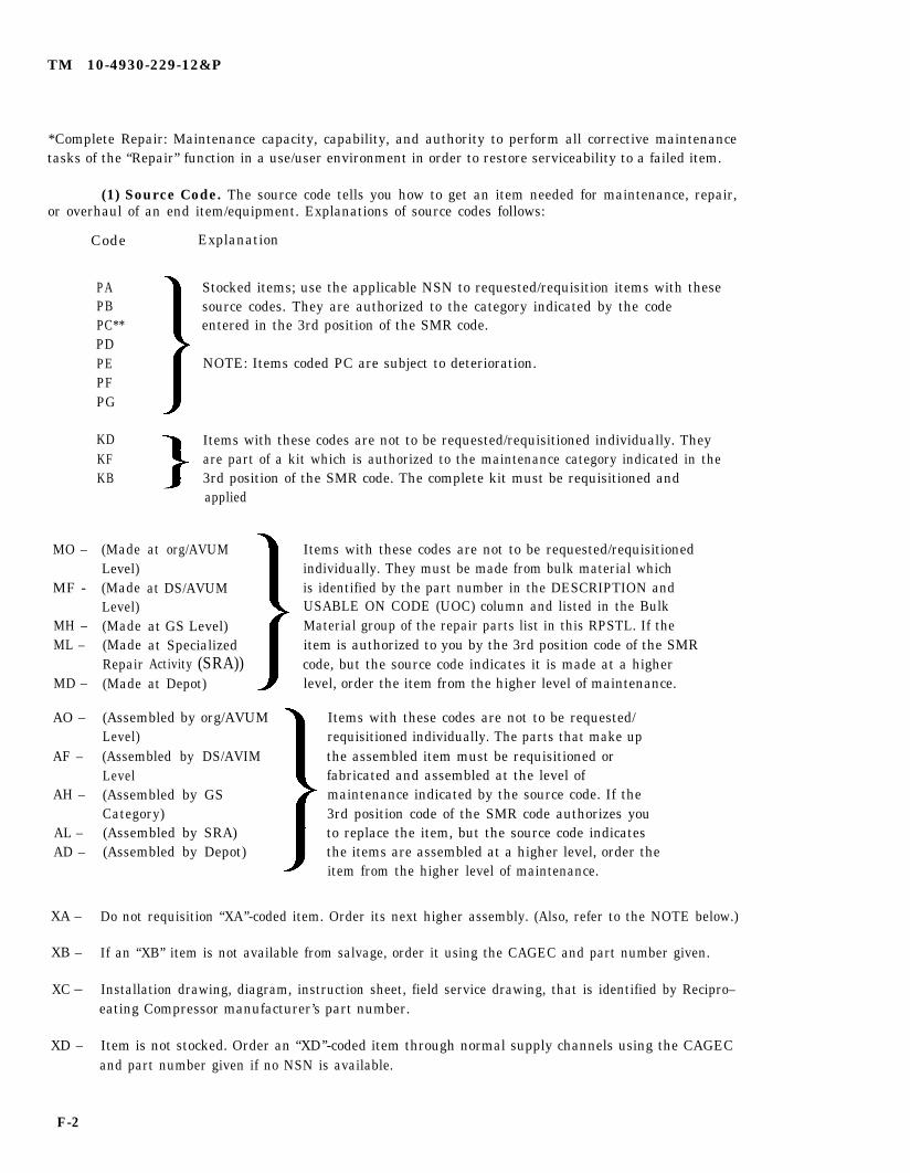
TM 10-4930-229-12&P
*Complete Repair: Maintenance capacity, capability, and authority to perform all corrective maintenancetasks of the “Repair” function in a use/user environment in order to restore serviceability to a failed item.
(1) Source Code. The source code tells you how to get an item needed for maintenance, repair,or overhaul of an end item/equipment. Explanations of source codes follows:
MO –
MF -
MH –ML –
MD –
AO –
AF –
AH –
AL –AD –
XA –
XB –
XC –
XD –
Code
PAPBPC**PDPEPFPG
KDKFKB
(MadeLevel)(MadeLevel)(Made(MadeRepair(Made
Explanation
Stocked items; use the applicable NSN to requested/requisition items with thesesource codes. They are authorized to the category indicated by the codeentered in the 3rd position of the SMR code.
NOTE: Items coded PC are subject to deterioration.
Items with these codes are not to be requested/requisitioned individually. Theyare part of a kit which is authorized to the maintenance category indicated in the3rd position of the SMR code. The complete kit must be requisitioned andapplied
at org/AVUM
at DS/AVUM
at GS Level)at SpecializedActivity (SRA))at Depot)
(Assembled by org/AVUMLevel)(Assembled by DS/AVIMLevel(Assembled by GSCategory)(Assembled by SRA)(Assembled by Depot)
Items with these codes are not to be requested/requisitionedindividually. They must be made from bulk material whichis identified by the part number in the DESCRIPTION andUSABLE ON CODE (UOC) column and listed in the BulkMaterial group of the repair parts list in this RPSTL. If theitem is authorized to you by the 3rd position code of the SMRcode, but the source code indicates it is made at a higherlevel, order the item from the higher level of maintenance.
Items with these codes are not to be requested/requisitioned individually. The parts that make upthe assembled item must be requisitioned orfabricated and assembled at the level ofmaintenance indicated by the source code. If the3rd position code of the SMR code authorizes youto replace the item, but the source code indicatesthe items are assembled at a higher level, order theitem from the higher level of maintenance.
Do not requisition “XA’’-coded item. Order its next higher assembly. (Also, refer to the NOTE below.)
If an “XB” item is not available from salvage, order it using the CAGEC and part number given.
Installation drawing, diagram, instruction sheet, field service drawing, that is identified by Recipro–eating Compressor manufacturer’s part number.
Item is not stocked. Order an “XD’’-coded item through normal supply channels using the CAGECand part number given if no NSN is available.
F-2

TM 10-4930-229-12&P
NOTE
Cannibalization or controlled exchange, when authorized, maybe used asa source of supply for items with the above source codes, except for thosesource coded “XA” or those aircraft support items restricted byrequirements of AR 750–1.
(2) Maintenance Code. Maintenance codes tells you the level(s) of maintenance authorizedto USE and REPAIR support items. The maintenance codes are entered in the third and fourth positionsof the SMR code as follows:
(a) The maintenance code entered in the third position tells you the lowest maintenancelevel authorized to remove, replace, and use an item. The maintenance code entered in the third positionwill indicate authorization to one of the following levels of maintenance.
Code Application/Explanation
C - Crew or operator maintenance done within organizational or aviation unit maintenance.
O— Organizational or aviation unit category can remove, replace, and use the item.
F— Direct support or aviation intermediate level can remove, replace, and use the item
H— General support level can remove, replace, and use the item.
L— Specialized repair activity can remove, replace, and use the item.
D— Depot level can remove, replace, and use the item.
(b) The maintenance code entered in the fourth position tells whether or not the item is tobe repaired and identifies the lowest maintenance level with the capability to do complete repair (i.e. ,perform all authorized repair functions.) NOTE: Some limited repair may be done on the item at a lowerlevel of maintenance, if authorized by the Maintenance Allocation Chart (MAC) and SMR codes. Thisposition will contain one of the following maintenance codes.
Code Application/Explanation
O— organizational or (aviation unit) is the lowest level that can do complete repair of the item.
F— Direct support or aviation intermediate is the lowest level that can do complete repair of the item.
H— General Support is the lowest level that can do complete repair of the item.
L — Specialized repair activity is the lowest level that can do complete repair of the item.
D— Depot is the lowest level that can do complete repair of the item.
Z— Nonreparable. No repair is authorized
B— No repair is authorized. (No parts or special tools are authorized for the maintenance of a “B’’codeditem). However, the item may be reconditioned by adjusting, lubricating, etc., at the user level.
(3) Recoverability Code. Recoverability codes are assigned to items to indicate thedisposition action on unserviceable items. The recoverability code is entered in the fifth position of theSMR Code as follows:
F-3
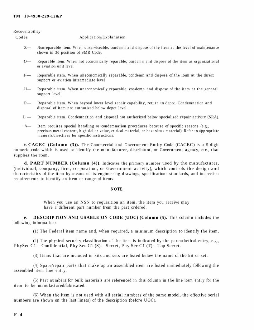
TM 10-4930-229-12&P
RecoverabilityCodes
Z—
O—
F—
H—
D—
L —
A—
Application/Explanation
Nonreparable item. When unserviceable, condemn and dispose of the item at the level of maintenanceshown in 3d position of SMR Code.
Reparable item. When not economically reparable, condemn and dispose of the item at organizationalor aviation unit level
Reparable item. When uneconomically reparable, condemn and dispose of the item at the directsupport or aviation intermediate level
Reparable item. When uneconomically reparable, condemn and dispose of the item at the generalsupport level.
Reparable item. When beyond lower level repair capability, return to depot. Condemnation anddisposal of item not authorized below depot level.
Reparable item. Condemnation and disposal not authorized below specialized repair activity (SRA).
Item requires special handling or condemnation procedures because of specific reasons (e.g.,precious metal content, high dollar value, critical material, or hazardous material). Refer to appropriatemanuals/directives for specific instructions.
C. CAGEC (Column (3)). The Commercial and Government Entity Code (CAGEC) is a 5-digitnumeric code which is used to identify the manufacturer, distributor, or Government agency, etc., thatsupplies the item.
d. PART NUMBER (Column (4)). Indicates the primary number used by the manufacturer,(individual, company, firm, corporation, or Government activity), which controls the design andcharacteristics of the item by means of its engineering drawings, specifications standards, and inspectionrequirements to identify an item or range of items.
e.following
NOTE
When you use an NSN to requisition an item, the item you receive mayhave a different part number from the part ordered.
DESCRIPTION AND USABLE ON CODE (UOC) (Column (5). This column includes theinformation:
(1) The Federal item name and, when required, a minimum description to identify the item.
(2) The physical security classification of the item is indicated by the parenthetical entry, e.g.,PhySec C1 – Confidential, Phy Sec C1 (S) – Secret, Phy Sec C1 (T) – Top Secret.
(3) Items that are included in kits and sets are listed below the name of the kit or set.
(4) Spare/repair parts that make up an assembled item are listed immediately following theassembled item line entry.
(5) Part numbers for bulk materials are referenced in this column in the line item entry for theitem to be manufactured/fabricated.
(6) When the item is not used with all serial numbers of the same model, the effective serialnumbers are shown on the last line(s) of the description (before UOC).
F-4
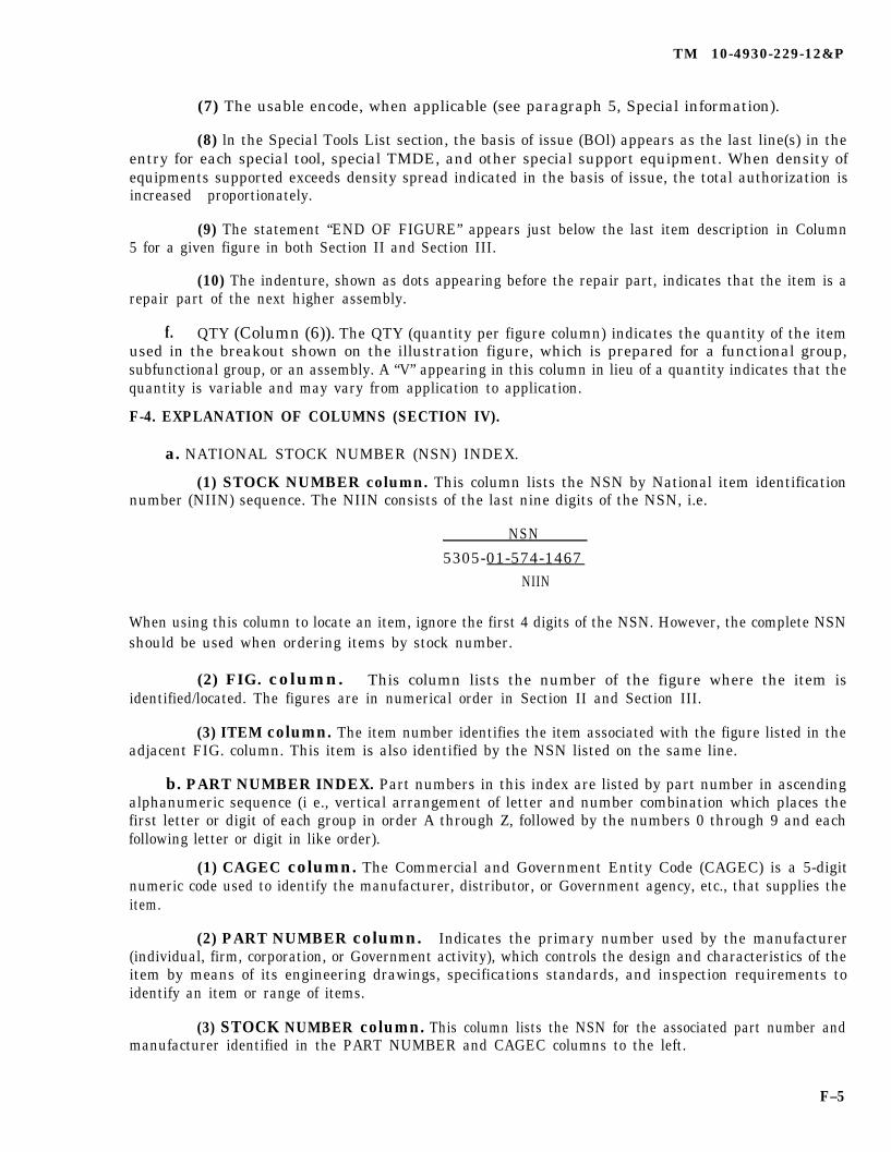
TM 10-4930-229-12&P
(7) The usable encode, when applicable (see paragraph 5, Special information).
(8) ln the Special Tools List section, the basis of issue (BOl) appears as the last line(s) in theentry for each special tool, special TMDE, and other special support equipment. When density ofequipments supported exceeds density spread indicated in the basis of issue, the total authorization isincreased proportionately.
(9) The statement “END OF FIGURE” appears just below the last item description in Column5 for a given figure in both Section II and Section III.
(10) The indenture, shown as dots appearing before the repair part, indicates that the item is arepair part of the next higher assembly.
f. QTY (Column (6)). The QTY (quantity per figure column) indicates the quantity of the itemused in the breakout shown on the illustration figure, which is prepared for a functional group,subfunctional group, or an assembly. A “V” appearing in this column in lieu of a quantity indicates that thequantity is variable and may vary from application to application.
F-4. EXPLANATION OF COLUMNS (SECTION IV).
a. NATIONAL STOCK NUMBER (NSN) INDEX.
(1) STOCK NUMBER column. This column lists the NSN by National item identificationnumber (NIIN) sequence. The NIIN consists of the last nine digits of the NSN, i.e.
NSN
5305-01-574-1467NIIN
When using this column to locate an item, ignore the first 4 digits of the NSN. However, the complete NSNshould be used when ordering items by stock number.
(2) FIG. column. This column lists the number of the figure where the item isidentified/located. The figures are in numerical order in Section II and Section III.
(3) ITEM column. The item number identifies the item associated with the figure listed in theadjacent FIG. column. This item is also identified by the NSN listed on the same line.
b. PART NUMBER INDEX. Part numbers in this index are listed by part number in ascendingalphanumeric sequence (i e., vertical arrangement of letter and number combination which places thefirst letter or digit of each group in order A through Z, followed by the numbers 0 through 9 and eachfollowing letter or digit in like order).
(1) CAGEC column. The Commercial and Government Entity Code (CAGEC) is a 5-digitnumeric code used to identify the manufacturer, distributor, or Government agency, etc., that supplies theitem.
(2) PART NUMBER column. Indicates the primary number used by the manufacturer(individual, firm, corporation, or Government activity), which controls the design and characteristics of theitem by means of its engineering drawings, specifications standards, and inspection requirements toidentify an item or range of items.
(3) STOCK NUMBER column. This column lists the NSN for the associated part number andmanufacturer identified in the PART NUMBER and CAGEC columns to the left.
F–5

TM 10-4930-229-12&P
(4) FIG. column. This column lists the number of the figure where the item isidentified/located in Sections II and III.
(5) ITEM column. The item number is that number assigned to the item as it appears in thefigure referenced in adjacent figure number column.
c. FIGURE AND ITEM NUMBER INDEX.
(1) FIG. column. This column lists the number of the figure where the item isidentified/located in Section II and III.
(2) ITEM column. The item number is that number assigned to the item as it appears in thefigure referenced in the adjacent figure number column.
(3) STOCK NUMBER column. This column lists the NSN for the item.
(4) CAGEC column. The Commercial and Government Entity Code (CAGEC) is a 5-digitnumeric code used to identify the manufacturer, distributor, or Government agency, etc., that supplies theitem.
(5) PART NUMBER column. Indicates the primary number used by the manufacturer(individual, firm, corporation, or Government activity), which controls the design and characteristics of theitem by means of its engineering drawings, specifications standards, and inspection requirements toidentify an item or range of items.
F-5. SPECIAL INFORMATION. USABLE ON CODE. The usable on code appears in the lower cornerof the Description column heading. Usable on codes are shown as UOC: . . . . .” in the Description Column(justified left) on the last line applicable item description/nomenclature. Uncoded items are applicable toall models.
F-6. HOW TO LOCATE REPAIR PARTS.
a. When National Stock Number or Part Number is NOT Known.
(1) First. Using the table of contents, determine the assembly group or subassembly groupto which the item belongs. This is necessary since figures are prepared for assembly groups andsubassembly groups, and listings are divided into the same groups.
(2) Second. Find the figure covering the assembly group or subassembly group to which theitem belongs.
F-6

TM 10-4930-229-12&P
(3) Third. identify the item on the figure and note the item number.
(4) Fourth. Refer to the Repair Parts List for the figure to find the part number for the itemnumber noted on the figure.
(5) Fifth. Refer to the Part Number Index to find the NSN, if assigned.
b. When National Stock Number or Part Number is Known.
(1) First. Using the Index of National Stock Numbers and Part Numbers, find the pertinentNational Stock Number or Part Number. The NSN index is in National Item Identification Number (NIIN)sequence (see c--4a.(1)). The part numbers in the Part Number index are listed in ascendingalphanumeric sequence (see paragraph c-4.b). Both indexes cross-reference you to the illustrationfigure and item number of the item you are looking for.
(2) Second. After finding the figure and item number, verify that the item is the one you arelooking for, then locate the item number in the repair parts list for the figure.
7. ABBREVIATIONS. Abbreviations used in this manual are listed in MlL–STD–12.
F-7

TM 10-4930-229-12&P
Figure F-1. Suction Hose Kit.
F-8 Change 1
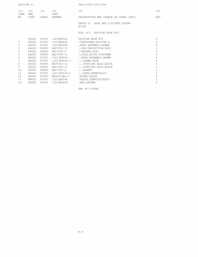
SECTION II TM10-4930-229-12&P
(1) (2) (3) (4) (5) (6)ITEM SMR PARTNO CODE CAGEC NUMBER DESCRIPTION AND USABLE ON CODES (UOC) QTY
GROUP 01 HOSE AND FITTINGS ASSEM-BLIES
FIG. F-1 SUCTION HOSE KIT
PDOOO 97403 13219E0501 SUCTION HOSE KIT 21 PAOZZ 97403 13219E0461 .CONTAINER,SUCTION H 22 PAOZZ 97403 13219E0464 .HOSE ASSEMBLY,NONME 63 PAOZZ 96906 MS27028-11 ..CAP,PROTECTIVE,DUST 14 PAOZZ 96906 MS27030-6 ..WASHER,FLAT 25 PAOZZ 96906 MS27029-11 ..PLUG,QUICK DISCONNE 16 XDOZZ 97403 13217E9444 ..HOSE ASSEMBLY,NONME 67 XDOZZ 97403 13217E9444-3 ...CLAMP,HOSE 48 XDOZZ 96906 MS27021-11 ...COUPLING HALF,QUICK 19 XDOZZ 96906 MS27025-11 ...COUPLING HALF,QUICK 110 PAOZZ 96906 MS27030-6 ...GASKET 111 XDOZZ 97403 13217E9444-1 ...HOSE,NONMETALIC 112 PAOZZ 96906 MS20470A4-5 .RIVET,SOLID 813 XBOZZ 97403 13219E0496 .PLATE,IDENTIFICATIO 114 PAOZZ 97403 13219E0462 .ROD,GROUND 2
END OF FIGURE
F-9
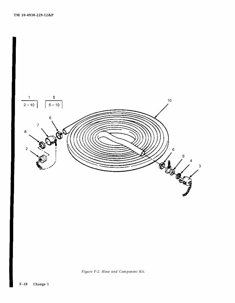
TM 10-4930-229-12&P
F–10
Figure F-2. Hose and Component Kit.
Change 1
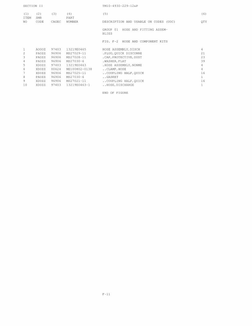
SECTION II TM10-4930-229-12&P
(1) (2) (3) (4) (5) (6)ITEM SMR PARTNO CODE CAGEC NUMBER DESCRIPTION AND USABLE ON CODES (UOC) QTY
GROUP 01 HOSE AND FITTING ASSEM-BLIES
FIG. F-2 HOSE AND COMPONENT KITS
1 AOOOZ 97403 13219E0465 HOSE ASSEMBLY,DISCH 42 PAOZZ 96906 MS27029-11 .PLUG,QUICK DISCONNE 213 PAOZZ 96906 MS27028-11 .CAP,PROTECTIVE,DUST 234 PAOZZ 96906 MS27030-6 .WASHER,FLAT 395 XDOZZ 97403 13219E0463 .HOSE ASSEMBLY,NONME 46 XDOZZ 00624 NE100802-0138 ..CLAMP,HOSE 47 XDOZZ 96906 MS27025-11 ..COUPLING HALF,QUICK 168 PAOZZ 96906 MS27030-6 ..GASKET 19 XDOZZ 96906 MS27021-11 ..COUPLING HALF,QUICK 1610 XDOZZ 97403 13219E0463-1 ..HOSE,DISCHARGE 1
END OF FIGURE
F-11
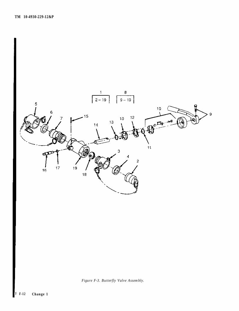
TM 10-4930-229-12&P
Figure F-3. Butterfly Valve Assembly.
F-12 Change 1
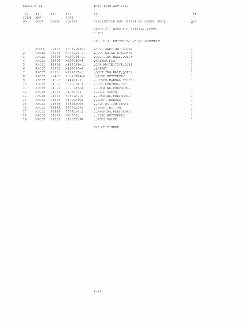
SECTION II TM10-4930-229-12&P
(1) (2) (3) (4) (5) (6)ITEM SMR PARTNO CODE CAGEC NUMBER DESCRIPTION AND USABLE ON CODES (UOC) QTY
GROUP 01 HOSE AND FITTING ASSEM-BLIES
FIG. F-3 BUTTERFLY VALVE ASSEMBLY
1 AOOOO 97403 13219E0467 VALVE ASSY,BUTTERFLY 22 PAOZZ 96906 MS27029-11 .PLUG,QUICK DISCONNE 13 PAOZZ 96906 MS27026-11 .COUPLING HALF,QUICK 24 PAOZZ 96906 MS27030-6 .WASHER,FLAT 25 PAOZZ 96906 MS27028-11 .CAP,PROTECTIVE,DUST 16 PAOZZ 96906 MS27030-6 .GASKET 27 PAOZZ 96906 MS27022-11 .COUPLING HALF,QUICK 18 PAOZZ 97403 13219E0468 .VALVE,BUTTERFLY 19 XDOZZ 91363 51410A191 ..LEVER,MANUAL CONTRO 110 XDOZZ 91363 55760B013 ..KIT,CONTROL,TOP 111 XDOZZ 91363 52561A224 ..PACKING,PREFORMED 112 XBOZZ 91363 5130C164 ..DISC VALVE 113 PAOZZ 91363 52561A115 ..PACKING,PREFORMED 114 XBOZZ 91363 51740A302 ..SHAFT,HANDLE 115 XBOZZ 91363 52325B005 ..PIN,BOTTOM SHAFT 116 XAOZZ 91363 51740A292 ..SHAFT,BOTTOM 117 XDOZZ 91363 52561A012 ..PACKING,PREFORMED 118 XBOZZ 19099 NPN0001 ..DISC,BUTTERFLY 119 XBOZZ 91363 51100E140 ..BODY,VALVE 1
END OF FIGURE
F-13
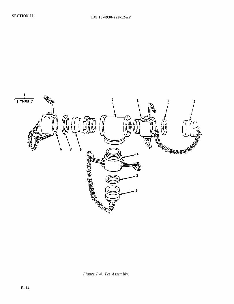
SECTION II TM 10-4930-229-12&P
Figure F-4. Tee Assembly.
F–14
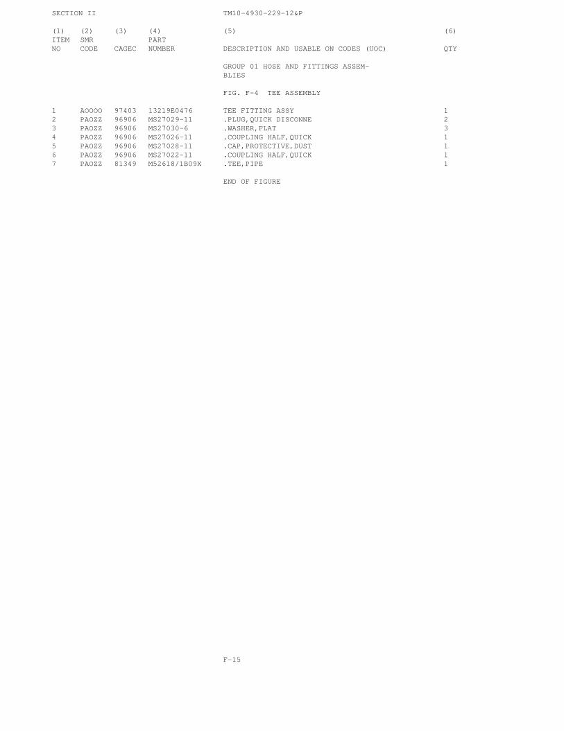
SECTION II TM10-4930-229-12&P
(1) (2) (3) (4) (5) (6)ITEM SMR PARTNO CODE CAGEC NUMBER DESCRIPTION AND USABLE ON CODES (UOC) QTY
GROUP 01 HOSE AND FITTINGS ASSEM-BLIES
FIG. F-4 TEE ASSEMBLY
1 AOOOO 97403 13219E0476 TEE FITTING ASSY 12 PAOZZ 96906 MS27029-11 .PLUG,QUICK DISCONNE 23 PAOZZ 96906 MS27030-6 .WASHER,FLAT 34 PAOZZ 96906 MS27026-11 .COUPLING HALF,QUICK 15 PAOZZ 96906 MS27028-11 .CAP,PROTECTIVE,DUST 16 PAOZZ 96906 MS27022-11 .COUPLING HALF,QUICK 17 PAOZZ 81349 M52618/1B09X .TEE,PIPE 1
END OF FIGURE
F-15
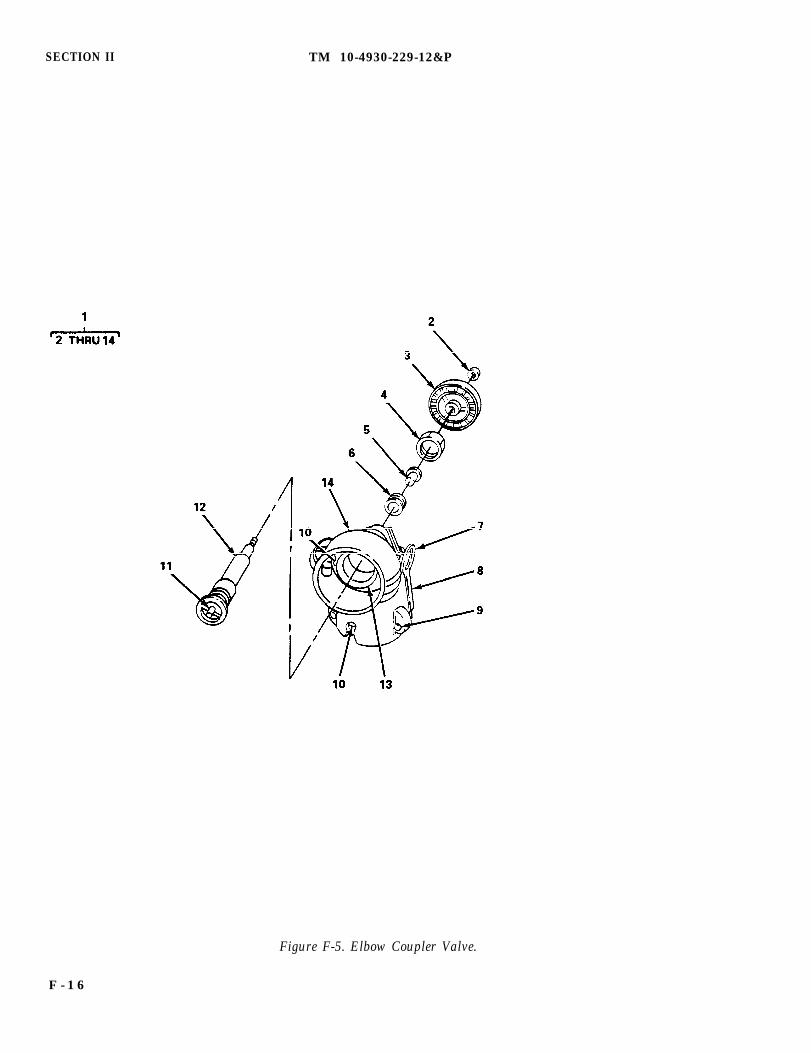
SECTION II TM 10-4930-229-12&P
Figure F-5. Elbow Coupler Valve.
F - 1 6

SECTION II TM10-4930-229-12&P
(1) (2) (3) (4) (5) (6)ITEM SMR PARTNO CODE CAGEC NUMBER DESCRIPTION AND USABLE ON CODES (UOC) QTY
GROUP 01 HOSE AND FITTING ASSEM-BLIES
FIG. F-5 ELBOW COUPLER VALVE
1 PAOZZ 97403 13219E0491 VALVE,ANGLE 12 XBOZZ 81718 H500RB .NUT,WHEEL 13 XBOZZ 81718 H11A .HANDWHEEL 14 XBOZZ 81718 H776B .NUT,PACKING 15 XAOZZ 81718 H185RB .GLAND,VALVE 16 PAOZZ 81718 H234M .PACKING,PREFORMED 17 XBOZZ 81718 H6451M .RING,VALVE 48 XBOZZ 81718 C1802B .CAM,VALVE 49 XBOZZ 81718 H6458RE .PIN,STRAIGHT 410 PAOZZ 96906 MS27030-6 .WASHER,FLAT 211 XBOZZ 81718 H407RE .PIN,THRUST 112 XAOZZ 81718 H403B .STEM,VALVE 113 XAOZZ 81718 H441B .RING,SEAT 114 XAOZZ 81718 D263A .BODY,VALVE 1
END OF FIGURE
F-17

TM 10-4930-22912&P
Figure F-6. Adapter Assembly, 3 In. x 2 In. and Adapter Assembly, Male x Male.
F-18 Change 1

SECTION II TM10-4930-229-12&P
(1) (2) (3) (4) (5) (6)ITEM SMR PARTNO CODE CAGEC NUMBER DESCRIPTION AND USABLE ON CODES (UOC) QTY
GROUP 01 HOSE AND FITTING ASSEMBLIES
FIG.F-6 ADAPTER ASSEMBLY, 3IN.X2 IN. AND ADAPTER ASSEMBLY,MALE X MALE
1 PAOZZ 96906 MS39352-9 NIPPLE,QUICK-DISCON 22 AOOOZ 97403 13219E0493 ADAPTER ASSEMBLY 13 PAOZZ 96906 MS27029-15 .PLUG,QUICK DISCONNE 14 PAOZZ 96906 MS27030-8 .GASKET 15 PAOZZ 96906 MS27028-11 .CAP,PROTECTIVE,DUST 16 PAOZZ 96906 MS27030-6 .WASHER,FLAT 17 XAOZZ 96906 MS49000-3 .COUPLING HALF,QUICK 1
END OF FIGURE
CHANGE 4 F-19

TM 10-4930-229-12&P
F-20 Change 1
Figure F-7. Adapter Assembly, 4 In. x 2 In.

SECTION II TM10-4930-229-12&P
(1) (2) (3) (4) (5) (6)ITEM SMR PARTNO CODE CAGEC NUMBER DESCRIPTION AND USABLE ON CODES (UOC) QTY
GROUP 01 HOSE AND FITTING ASSEM-BLIES
FIG. F-7 ADAPTER ASSEMBLY, 4 IN. X2 IN.
1 AOOOO 97403 13219E0466 ADAPTER ASSEMBLY 4IN.FEMALE X 12IN.MALE
2 PAOZZ 96906 MS27029-17 .PLUG,QUICK DISCONNE 13 PAOZZ 96906 MS27030-9 .GASKET 14 PAOZO 96906 MS27028-11 .CAP,QUICK DISCONNEC 15 PAOZZ 96906 MS27030-6 .GASKET 16 XAOZZ 96906 MS49000-17 .REDUCER,QUICK DISCO 1
END OF FIGURE
F-21

TM 10-4930-229-12&P
NOTESEE TM 5-4930-226-12&P FOR PARTS BREAKOUT FOR THE NOZZLEASSEMBLY (1) AND ADAPTER (2).
Figure F-8. Closed-CIrcuit Refueling Nozzle and Gravity-Feed Adapter.
F-22 Change 1
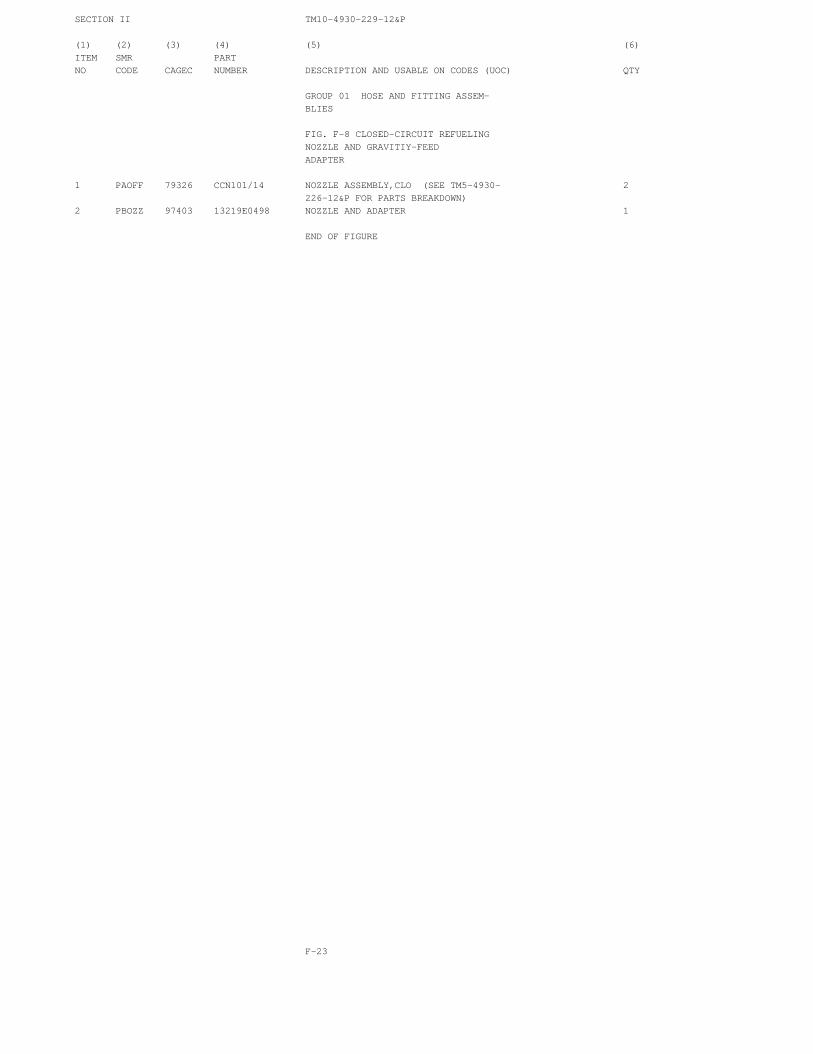
SECTION II TM10-4930-229-12&P
(1) (2) (3) (4) (5) (6)ITEM SMR PARTNO CODE CAGEC NUMBER DESCRIPTION AND USABLE ON CODES (UOC) QTY
GROUP 01 HOSE AND FITTING ASSEM-BLIES
FIG. F-8 CLOSED-CIRCUIT REFUELINGNOZZLE AND GRAVITIY-FEEDADAPTER
1 PAOFF 79326 CCN101/14 NOZZLE ASSEMBLY,CLO (SEE TM5-4930- 2226-12&P FOR PARTS BREAKDOWN)
2 PBOZZ 97403 13219E0498 NOZZLE AND ADAPTER 1
END OF FIGURE
F-23

SECTION II TM 10-4930-229-12&P
Figure F-9. Wye Fitting Assembly.
F-24
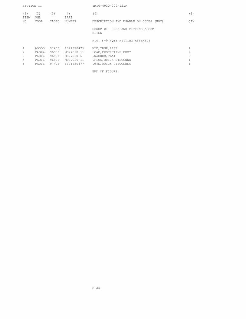
SECTION II TM10-4930-229-12&P
(1) (2) (3) (4) (5) (6)ITEM SMR PARTNO CODE CAGEC NUMBER DESCRIPTION AND USABLE ON CODES (UOC) QTY
GROUP 01 HOSE AND FITTING ASSEM-BLIES
FIG. F-9 WQYE FITTING ASSEMBLY
1 AOOOO 97403 13219E0475 WYE,TRUE,PIPE 12 PAOZZ 96906 MS27028-11 .CAP,PROTECTIVE,DUST 23 PAOZZ 96906 MS27030-6 .WASHER,FLAT 34 PAOZZ 96906 MS27029-11 .PLUG,QUICK DISCONNE 15 PAOZZ 97403 13219E0477 .WYE,QUICK DISCONNEC 1
END OF FIGURE
F-25
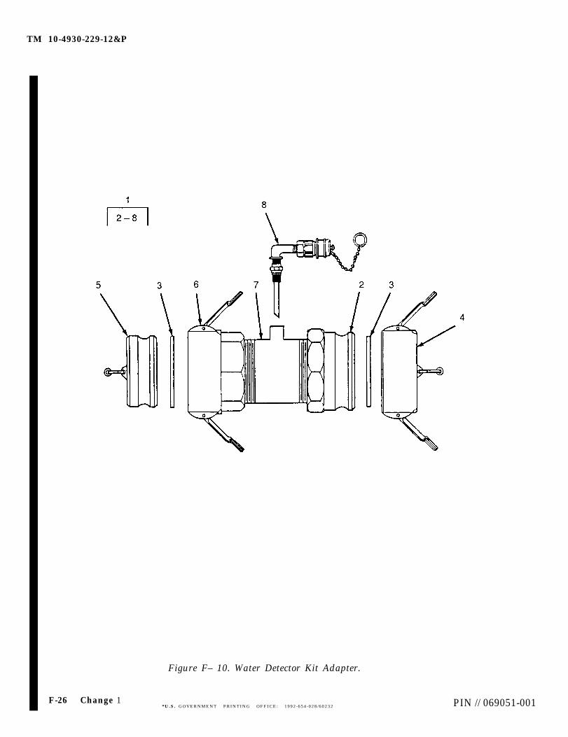
TM 10-4930-229-12&P
F-26 Change 1
Figure F– 10. Water Detector Kit Adapter.
*U.S. GOVERNMENT PRINTING OFFICE: 1992-654-028/60232 PIN // 069051-001
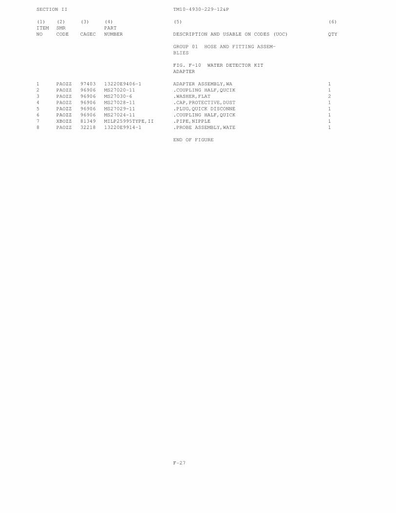
SECTION II TM10-4930-229-12&P
(1) (2) (3) (4) (5) (6)ITEM SMR PARTNO CODE CAGEC NUMBER DESCRIPTION AND USABLE ON CODES (UOC) QTY
GROUP 01 HOSE AND FITTING ASSEM-BLIES
FIG. F-10 WATER DETECTOR KITADAPTER
1 PAOZZ 97403 13220E9406-1 ADAPTER ASSEMBLY,WA 12 PAOZZ 96906 MS27020-11 .COUPLING HALF,QUCIK 13 PAOZZ 96906 MS27030-6 .WASHER,FLAT 24 PAOZZ 96906 MS27028-11 .CAP,PROTECTIVE,DUST 15 PAOZZ 96906 MS27029-11 .PLUG,QUICK DISCONNE 16 PAOZZ 96906 MS27024-11 .COUPLING HALF,QUICK 17 XBOZZ 81349 MILP25995TYPE,II .PIPE,NIPPLE 18 PAOZZ 32218 13220E9914-1 .PROBE ASSEMBLY,WATE 1
END OF FIGURE
F-27
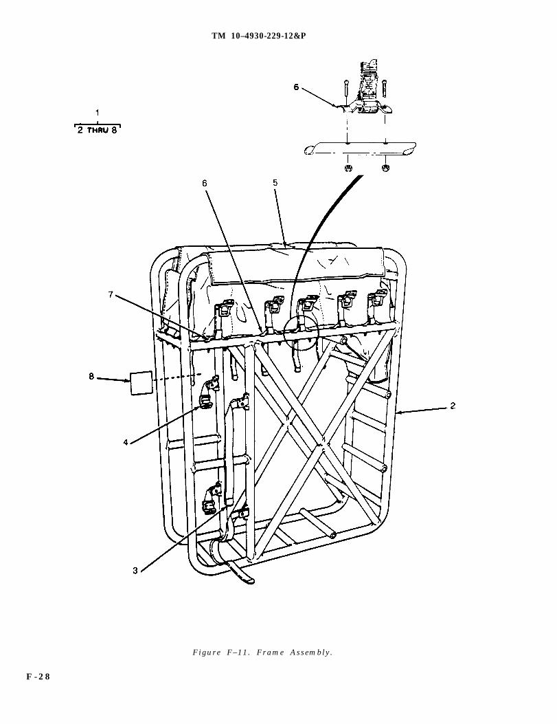
TM 10–4930-229-12&P
Figure F–11. Frame Assembly.
F - 2 8
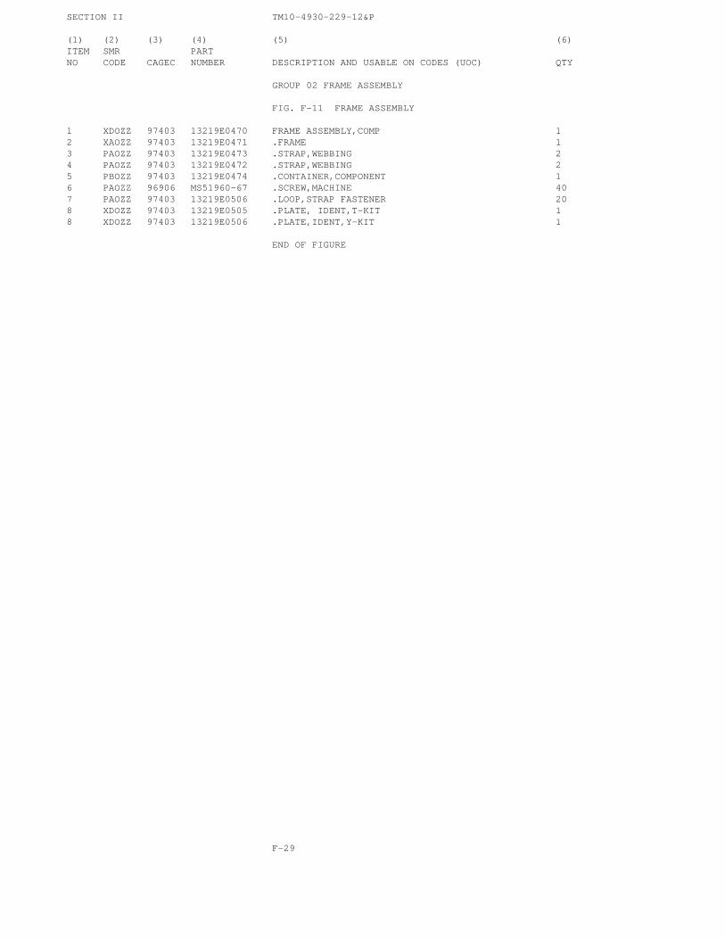
SECTION II TM10-4930-229-12&P
(1) (2) (3) (4) (5) (6)ITEM SMR PARTNO CODE CAGEC NUMBER DESCRIPTION AND USABLE ON CODES (UOC) QTY
GROUP 02 FRAME ASSEMBLY
FIG. F-11 FRAME ASSEMBLY
1 XDOZZ 97403 13219E0470 FRAME ASSEMBLY,COMP 12 XAOZZ 97403 13219E0471 .FRAME 13 PAOZZ 97403 13219E0473 .STRAP,WEBBING 24 PAOZZ 97403 13219E0472 .STRAP,WEBBING 25 PBOZZ 97403 13219E0474 .CONTAINER,COMPONENT 16 PAOZZ 96906 MS51960-67 .SCREW,MACHINE 407 PAOZZ 97403 13219E0506 .LOOP,STRAP FASTENER 208 XDOZZ 97403 13219E0505 .PLATE, IDENT,T-KIT 18 XDOZZ 97403 13219E0506 .PLATE,IDENT,Y-KIT 1
END OF FIGURE
F-29

SECTION II TM 10-4930-229-12&P
Figure F–12. Pump/Engine Assembly.
F–30

SECTION II TM10-4930-229-12&P
(1) (2) (3) (4) (5) (6)ITEM SMR PARTNO CODE CAGEC NUMBER DESCRIPTION AND USABLE ON CODES (UOC) QTY
GROUP 03 PUMP AND ENGINE ASSEM-BLY
FIG. F-12 PUMP AND ENGINE ASSEM-BLY
1 PDOFH 97403 13219E3950 PUMPING ASSEMBLY,FL (SEE TM10-4320- 1256-14&P FOR PARTS BREAKDOWN)
END OF FIGURE
F-31
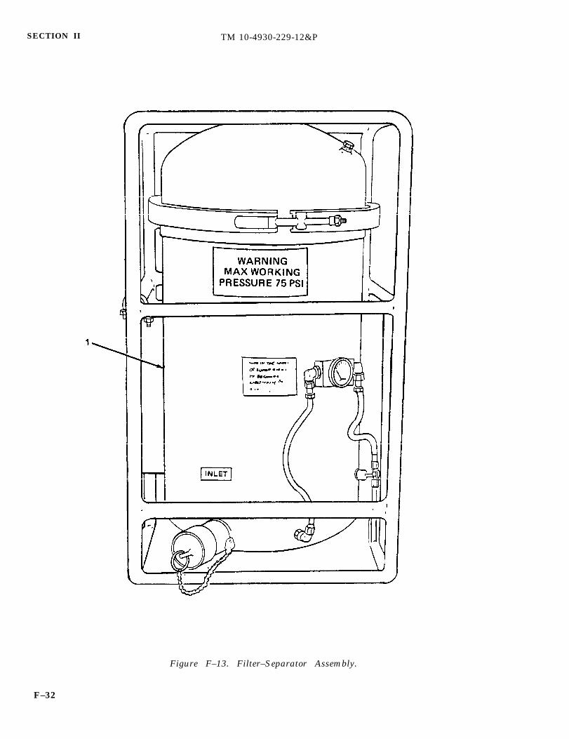
SECTION II TM 10-4930-229-12&P
Figure F–13. Filter–Separator Assembly.
F–32

SECTION II TM10-4930-229-12&P
(1) (2) (3) (4) (5) (6)ITEM SMR PARTNO CODE CAGEC NUMBER DESCRIPTION AND USABLE ON CODES (UOC) QTY
GROUP 04 FILTER/SEPARATOR
FIG. F-13 FILTER-SEPARATOR AS-SEMBLY
1 PAOFF 97403 13217E5350 FILTER-SEPARATOR,LI (SEE TM5-4330- 1217-12 FOR PARTS BREAKDOWN)
END OF FIGURE
F-33

TM 10-4930-229-12&P
SECTION III. SPECIAL TOOLS LIST
NOT APPLICABLE
F-34
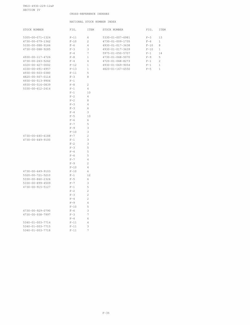
TM10-4930-229-12&PSECTION IV
CROSS-REFERENCE INDEXES
NATIONAL STOCK NUMBER INDEX
STOCK NUMBER FIG. ITEM STOCK NUMBER FIG. ITEM
5305-00-071-1324 F-11 6 5330-01-007-6981 F-3 134730-00-079-1362 F-10 2 4730-01-009-1735 F-6 15330-00-088-9166 F-6 4 4930-01-017-3638 F-10 84730-00-088-9285 F-3 3 4930-01-017-3639 F-10 1
F-4 7 5975-01-050-5707 F-1 144930-00-117-4726 F-8 1 4730-01-068-5070 F-9 54730-00-263-5262 F-4 4 4720-01-068-8273 F-1 24320-00-427-0002 F-12 1 4930-01-069-9054 F-1 14330-00-491-4957 F-13 1 4820-01-167-6550 F-5 14930-00-503-0380 F-11 54820-00-507-0114 F-3 84930-00-513-9906 F-14930-00-516-0839 F-8 25330-00-612-2414 F-1 4
F-1 10F-2 4F-2 8F-3 4F-3 6F-4 3F-5 10F-6 6F-7 5F-9 3F-10 3
4730-00-640-6188 F-7 24730-00-649-9100 F-1 3
F-2 3F-3 5F-4 5F-6 5F-7 4F-9 2F-10 4
4730-00-649-9103 F-10 65320-00-721-5210 F-1 125330-00-860-2326 F-5 65330-00-899-4509 F-7 34730-00-915-5127 F-1 5
F-2 2F-3 2F-4 2F-9 4F-10 5
4730-00-929-0790 F-6 34730-00-938-7997 F-3 7
F-4 65340-01-003-7714 F-11 45340-01-003-7715 F-11 35340-01-003-7718 F-11 7
F-35

TM10-4930-229-12&PSECTION IV
CROSS-REFERENCE INDEXES
PART NUMBER INDEXCAGEC PART NUMBER STOCK NUMBER FIG. ITEM
79326 CCN101/14 4930-00-117-4726 F-8 181718 C1802B F-5 881718 D263A F-5 1481718 H11A F-5 381718 H185RB F-5 581718 H234M 5330-00-860-2326 F-5 681718 H403B F-5 1281718 H407RE F-5 1381718 H441B F-5 281718 H500RB F-5 281718 H6451M F-5 781718 H6458RE F-5 981718 H776B F-5 481349 MILP25995TYPE,II F-10 796906 MS20470A4-5 5320-00-721-5210 F-1 1296906 MS27020-11 4730-00-079-1362 F-10 296906 MS27021-11 F-1 8
F-2 996906 MS27022-11 4730-00-938-7997 F-3 7
F-4 696906 MS27024-11 4730-00-649-9103 F-10 696906 MS27025-11 F-1 9
F-2 796906 MS27026-11 4730-00-088-9285 F-3 3
F-4 496906 MS27028-11 4730-00-649-9100 F-1 3
F-2 3F-3 5F-4 5F-6 5F-7 4F-9 2F-10 4
96906 MS27029-11 4730-00-915-5127 F-1 5F-2 2F-3 2F-4 2F-9 4F-10 5
96906 MS27029-15 4730-00-929-0790 F-6 396906 MS27029-17 4730-00-640-6188 F-7 296906 MS27030-6 5330-00-612-2414 F-1 4
F-1 10F-2 4F-2 8F-3 4F-3 6F-4 3F-5 10F-6 6F-7 5
F-36
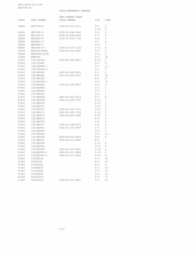
TM10-4930-229-12&PSECTION IV
CROSS-REFERENCE INDEXES
PART NUMBER INDEXCAGEC PART NUMBER STOCK NUMBER FIG. ITEM
96906 MS27030-6 5330-00-612-2414 F-9 3F-10 3
96906 MS27030-8 5330-00-088-9166 F-6 496906 MS27030-9 5330-00-899-4509 F-7 396906 MS39352-9 4730-01-009-1735 F-6 196906 MS49000-17 F-7 696906 MS49000-3 F-6 796906 MS51960-67 5305-00-071-1324 F-11 681349 M52618/1B09X 4730-00-263-5262 F-4 700624 NE100802-0138 F-2 619099 NPN0001 F-3 1897403 13217E5350 4330-00-491-4957 F-13 197403 13217E9444 F-1 697403 13217E9444-1 F-1 1197403 13217E9444-3 F-1 797403 13219E0461 4930-01-069-9054 F-1 197403 13219E0462 5975-01-050-5707 F-1 1497403 13219E0463 F-2 597403 13219E0463-1 F-2 1097403 13219E0464 4720-01-068-8273 F-1 297403 13219E0465 F-2 197403 13219E0466 F-7 197403 13219E0467 F-3 197403 13219E0468 4820-00-507-0114 F-3 897403 13219E0469 5340-01-003-7718 F-11 797403 13219E0470 F-11 197403 13219E0471 F-11 297403 13219E0472 5340-01-003-7714 F-11 497403 13219E0473 5340-01-003-7715 F-11 397403 13219E0474 4930-00-503-0380 F-11 597403 13219E0475 F-9 197403 13219E0476 F-4 197403 13219E0477 4730-01-068-5070 F-9 597403 13219E0491 4820-01-167-6550 F-5 197403 13219E0493 F-6 297403 13219E0496 F-1 1397403 13219E0498 4930-00-516-0839 F-8 297403 13219E0501 4930-00-513-9906 F-197403 13219E0505 F-11 897403 13219E0506 F-11 897403 13219E3950 4320-00-427-0002 F-12 197403 13220E9406-1 4930-01-017-3639 F-10 132218 13220E9914-1 4930-01-017-3638 F-10 891363 51100E140 F-3 1991363 5130C164 F-3 1291363 51410A191 F-3 991363 51740A292 F-3 1691363 51740A302 F-3 1491363 52325B005 F-3 1591363 52561A012 F-3 1791363 52561A115 5330-01-007-6981 F-3 13
F-37

TM10-4930-229-12&PSECTION IV
CROSS-REFERENCE INDEXES
PART NUMBER INDEXCAGEC PART NUMBER STOCK NUMBER FIG. ITEM
91363 52561A224 F-3 1191363 55760B013 F-3 10
F-38

TM10-4930-229-12&PSECTION IV
CROSS-REFERENCE INDEXES
FIGURE AND ITEM NUMBER INDEXFIG. ITEM STOCK NUMBER CAGEC PART NUMBER
F-1 4930-00-513-9906 97403 13219E0501F-1 1 4930-01-069-9054 97403 13219E0461F-1 2 4720-01-068-8273 97403 13219E0464F-1 3 4730-00-649-9100 96906 MS27028-11F-1 4 5330-00-612-2414 96906 MS27030-6F-1 5 4730-00-915-5127 96906 MS27029-11F-1 6 97403 13217E9444F-1 7 97403 13217E9444-3F-1 8 96906 MS27021-11F-1 9 96906 MS27025-11F-1 10 5330-00-612-2414 96906 MS27030-6F-1 11 97403 13217E9444-1F-1 12 5320-00-721-5210 96906 MS20470A4-5F-1 13 97403 13219E0496F-1 14 5975-01-050-5707 97403 13219E0462F-2 1 97403 13219E0465F-2 2 4730-00-915-5127 96906 MS27029-11F-2 3 4730-00-649-9100 96906 MS27028-11F-2 4 5330-00-612-2414 96906 MS27030-6F-2 5 97403 13219E0463F-2 6 00624 NE100802-0138F-2 7 96906 MS27025-11F-2 8 5330-00-612-2414 96906 MS27030-6F-2 9 96906 MS27021-11F-2 10 97403 13219E0463-1F-3 1 97403 13219E0467F-3 2 4730-00-915-5127 96906 MS27029-11F-3 3 4730-00-088-9285 96906 MS27026-11F-3 4 5330-00-612-2414 96906 MS27030-6F-3 5 4730-00-649-9100 96906 MS27028-11F-3 6 5330-00-612-2414 96906 MS27030-6F-3 7 4730-00-938-7997 96906 MS27022-11F-3 8 4820-00-507-0114 97403 13219E0468F-3 9 91363 51410A191F-3 10 91363 55760B013F-3 11 91363 52561A224F-3 12 91363 5130C164F-3 13 5330-01-007-6981 91363 52561A115F-3 14 91363 51740A302F-3 15 91363 52325B005F-3 16 91363 51740A292F-3 17 91363 52561A012F-3 18 19099 NPN0001F-3 19 91363 51100E140F-4 1 97403 13219E0476F-4 2 4730-00-915-5127 96906 MS27029-11F-4 3 5330-00-612-2414 96906 MS27030-6F-4 4 4730-00-088-9285 96906 MS27026-11F-4 5 4730-00-649-9100 96906 MS27028-11F-4 6 4730-00-938-7997 96906 MS27022-11F-4 7 4730-00-263-5262 81349 M52618/1B09X
F-39
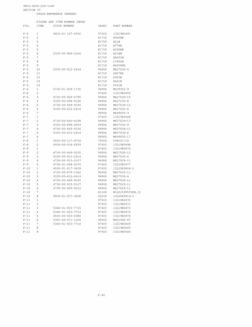
TM10-4930-229-12&PSECTION IV
CROSS-REFERENCE INDEXES
FIGURE AND ITEM NUMBER INDEXFIG. ITEM STOCK NUMBER CAGEC PART NUMBER
F-5 1 4820-01-167-6550 97403 13219E0491F-5 2 81718 H500RBF-5 3 81718 H11AF-5 4 81718 H776BF-5 5 81718 H185RBF-5 6 5330-00-860-2326 81718 H234MF-5 7 81718 H6451MF-5 8 81718 C1802BF-5 9 81718 H6458REF-5 10 5330-00-612-2414 96906 MS27030-6F-5 11 81718 H407REF-5 12 81718 H403BF-5 13 81718 H441BF-5 14 81718 D263AF-6 1 4730-01-009-1735 96906 MS39352-9F-6 2 97403 13219E0493F-6 3 4730-00-929-0790 96906 MS27029-15F-6 4 5330-00-088-9166 96906 MS27030-8F-6 5 4730-00-649-9100 96906 MS27028-11F-6 6 5330-00-612-2414 96906 MS27030-6F-6 7 96906 MS49000-3F-7 1 97403 13219E0466F-7 2 4730-00-640-6188 96906 MS27029-17F-7 3 5330-00-899-4509 96906 MS27030-9F-7 4 4730-00-649-9100 96906 MS27028-11F-7 5 5330-00-612-2414 96906 MS27030-6F-7 6 96906 MS49000-17F-8 1 4930-00-117-4726 79326 CCN101/14F-8 2 4930-00-516-0839 97403 13219E0498F-9 1 97403 13219E0475F-9 2 4730-00-649-9100 96906 MS27028-11F-9 3 5330-00-612-2414 96906 MS27030-6F-9 4 4730-00-915-5127 96906 MS27029-11F-9 5 4730-01-068-5070 97403 13219E0477F-10 1 4930-01-017-3639 97403 13220E9406-1F-10 2 4730-00-079-1362 96906 MS27020-11F-10 3 5330-00-612-2414 96906 MS27030-6F-10 4 4730-00-649-9100 96906 MS27028-11F-10 5 4730-00-915-5127 96906 MS27029-11F-10 6 4730-00-649-9103 96906 MS27024-11F-10 7 81349 MILP25995TYPE,IIF-10 8 4930-01-017-3638 32218 13220E9914-1F-11 1 97403 13219E0470F-11 2 97403 13219E0471F-11 3 5340-01-003-7715 97403 13219E0473F-11 4 5340-01-003-7714 97403 13219E0472F-11 5 4930-00-503-0380 97403 13219E0474F-11 6 5305-00-071-1324 96906 MS51960-67F-11 7 5340-01-003-7718 97403 13219E0469F-11 8 97403 13219E0505F-11 8 97403 13219E0506
F-40

TM10-4930-229-12&PSECTION IV
CROSS-REFERENCE INDEXES
FIGURE AND ITEM NUMBER INDEXFIG. ITEM STOCK NUMBER CAGEC PART NUMBER
F-12 1 4320-00-427-0002 97403 13219E3950F-13 1 4330-00-491-4957 97403 13217E5350
F-41/(F-42BLANK)

TM 10-4930-229-12&P
INDEX
Subject Paragraph
A
Adapter Assemblies . . . . . . . . . . . . . . . . . . . . . . . . . . . . . . . . . . . . . . . . . . . . . . . . . . . . . . . . . . . . . . . . . .Adapter Nozzle . . . . . . . . . . . . . . . . . . . . . . . . . . . . . . . . . . . . . . . . . . . . . . . . . . . . . . . . . . . . . . . . . . . . .Adapter, Water Detector Kit . . . . . . . . . . . . . . . . . . . . . . . . . . . . . . . . . . . . . . . . . . . . . . . . . . . . . . . . . . . .Administrative Storage . . . . . . . . . . . . . . . . . . . . . . . . . . . . . . . . . . . . . . . . . . . . . . . . . . . . . . . . . . . . . . . .Appendices:
A –B –C -D -E –F –
References . . . . . . . . . . . . . . . . . . . . . . . . . . . . . . . . . . . . . . . . . . . . . . . . . . . . . . . . . . . . . . . . .Maintenance Allocation Chart.... . . . . . . . . . . . . . . . . . . . . . . . . . . . . . . . . . . . . . . . . . . . . . . .Components of End ltem and Basic Issue Items Lists . . . . . . . . . . . . . . . . . . . . . . . . . . . . . . . .Additional Authorization List.... . . . . . . . . . . . . . . . . . . . . . . . . . . . . . . . . . . . . . . . . . . . . . . . .Expendable/Durable Supplies and Materials List . . . . . . . . . . . . . . . . . . . . . . . . . . . . . . . . . . . .Repair Parts and Special Tools List . . . . . . . . . . . . . . . . . . . . . . . . . . . . . . . . . . . . . . . . . . . . . .
Assembly and Preparation for Use . . . . . . . . . . . . . . . . . . . . . . . . . . . . . . . . . . . . . . . . . . . . . . . . . . . . . . .
B
4-164-174-194-22
A-1B-1C-1D-1E-1F-12-11
Butterfly Valve Assembly . . . . . . . . . . . . . . . . . . . . . . . . . . . . . . . . . . . . . . . . . . . . . . . . . . . . . . . . . . . . . . 4-13
C
Closed Circuit Refueling Nozzle. . . . . . . . . . . . . . . . . . . . . . . . . . . . . . . . . . . . . . . . . . . . . . . . . . . . . . . . . 3-12Collapsible Drum . . . . . . . . . . . . . . . . . . . . . . . . . . . . . . . . . . . . . . . . . . . . . . . . . . . . . . . . . . . . . . . . . . . . . 3-11
D
Destruction of Army Material to Prevent Enemy Use . . . . . . . . . . . . . . . . . . . . . . . . . . . . . . . . . . . . . . . . . 1-3Discharge Hose Assembly... . . . . . . . . . . . . . . . . . . . . . . . . . . . . . . . . . . . . . . . . . . . . . . . . . . . . . . ...3-5
E
Elbow Coupler Valve . . . . . . . . . . . . . . . . . . . . . . . . . . . . . . . . . . . . . . . . . . . . . . . . . . . . . . . . . . . . . . . . ..4-14Elbow Coupler Valve and Butterfly Valve Assembly Controls and lndicators . . . . . . . . . . . . . . . . . . . . . . . 2-2Equipment Characteristics, Capabilities and Features . . . . . . . . . . . . . . . . . . . . . . . . . . . . . . . . . . . . . . . . 1-6Equipment Data . . . . . . . . . . . . . . . . . . . . . . . . . . . . . . . . . . . . . . . . . . . . . . . . . . . . . . . . . . . . . . . . . . . . . 1-8
F
Filter/Separator . . . . . . . . . . . . . . . . . . . . . . . . . . . . . . . . . . . . . . . . . . . . . . . . . . . . . . . . . . . . . . . . . . .3-10Filter/Separator Controls and lndicators . . . . . . . . . . . . . . . . . . . . . . . . . . . . . . . . . . . . . . . . . . . . . . . . 2-3Fittings and Adapter . . . . . . . . . . . . . . . . . . . . . . . . . . . . . . . . . . . . . . . . . . . . . . . . . . . . . . . . . . . . . . .3-7Frame Assembly . . . . . . . . . . . . . . . . . . . . . . . . . . . . . . . . . . . . . . . . . . . . . . . . . . . . . . . . . . . . . . . . . . 4-20
Index 1
TM 10-4930-229-12&P
INDEX (cont)
SubjectG
Paragraph
General, PMCS . . . . . . . . . . . . . . . . . . . . . . . . . . . . . . . . . . . . . . . . . . . . . . . . . . . . . . . . . . . . . . . . . . . ...2-5General, Principles of Operation . . . . . . . . . . . . . . . . . . . . . . . . . . . . . . . . . . . . . . . . . . . . . . . . . . . . . . . . . 1-10Ground Rod . . . . . . . . . . . . . . . . . . . . . . . . . . . . . . . . . . . . . . . . . . . . . . . . . . . . . . . . . . . . . . . . . . . . . . ...4-12
H
Hose Assembly,Discharge . . . . . . . . . . . . . . . . . . . . . . . . . . . . . . . . . . . . . . . . . . . . . . . . . . . . . . . . . . . . . . . . . . . . . .4-10Suction . . . . . . . . . . . . . . . . . . . . . . . . . . . . . . . . . . . . . . . . . . . . . . . . . . . . . . . . . . . . . . . . . . . . . ...4-11
Hose Frame Assembly . . . . . . . . . . . . . . . . . . . . . . . . . . . . . . . . . . . . . . . . . . . . . . . . . . . . . . . . . . . . . ...3-8
I
Inspection and Service . . . . . . . . . . . . . . . . . . . . . . . . . . . . . . . . . . . . . . . . . . . . . . . . . . . . . . . . . . . . . ...4-5
J, K
L
Location and Description of Major Components . . . . . . . . . . . . . . . . . . . . . . . . . . . . . . . . . . . . . . . . . . . . . 1-7Lubrication instruction, General. . . . . . . . . . . . . . . . . . . . . . . . . . . . . . . . . . . . . . . . . . . . . . . . . . . . . . ...3-1
M
Maintenance Forms and Records . . . . . . . . . . . . . . . . . . . . . . . . . . . . . . . . . . . . . . . . . . . . . . . . . . . . . . . . 1-2
N
Nozzle Adapter . . . . . . . . . . . . . . . . . . . . . . . . . . . . . . . . . . . . . . . . . . . . . . . . . . . . . . . . . . . . . . . . . . . ...4-17
0
Operating Procedures . . . . . . . . . . . . . . . . . . . . . . . . . . . . . . . . . . . . . . . . . . . . . . . . . . . . . . . . . . . . . . . . . 2-12Operation,
Extreme Cold . . . . . . . . . . . . . . . . . . . . . . . . . . . . . . . . . . . . . . . . . . . . . . . . . . . . . . . . . . . . . . . . . . . . 2-14Extreme Heat . . . . . . . . . . . . . . . . . . . . . . . . . . . . . . . . . . . . . . . . . . . . . . . . . . . . . . . . . . . . . . . . . . . 2-15Dusty or Shady Areas . . . . . . . . . . . . . . . . . . . . . . . . . . . . . . . . . . . . . . . . . . . . . . . . . . . . . . . . . . . . .2-16Rainy or Humid Conditions . . . . . . . . . . . . . . . . . . . . . . . . . . . . . . . . . . . . . . . . . . . . . . . . . . . . . . . . .2-17Saltwater Areas . . . . . . . . . . . . . . . . . . . . . . . . . . . . . . . . . . . . . . . . . . . . . . . . . . . . . . . . . . . . . .2-18High Altitudes . . . . . . . . . . . . . . . . . . . . . . . . . . . . . . . . . . . . . . . . . . . . . . . . . . . . . . . . . . . . . . . . . . . 2-19
Operator Controls and lndicators . . . . . . . . . . . . . . . . . . . . . . . . . . . . . . . . . . . . . . . . . . . . . . . . . . . . . . .2-1Operator Maintenance . . . . . . . . . . . . . . . . . . . . . . . . . . . . . . . . . . . . . . . . . . . . . . . . . . . . . . . . .3-4
Operator PMCS. . . . . . . . . . ........ .... ..... . . . . . . . . . . . . . . . . . . . . . . . . . . . . . . . . . . . . . . . . . . . . . . . . . . . . . . . . . . . . . . . . . . . . . . . . .. ... ...2-10Operator Troubleshooting . . . . . . . . . . . . . . . . . . . . . . . . . . . . . . . . . . . . . . . . . . . . . . . . . . . . . . . . . . . .3-3
Index 2

TM 10-4930-229-12&P
INDEX (cont)
Subject ParagraphP
Preparation for Movement . . . . . . . . . . . . . . . . . . . . . . . . . . . . . . . . . . . . . . . . . . . . . . . . . . . . . . . . . . . . .2-13Preparation for Storage or Shipment . . . . . . . . . . . . . . . . . . . . . . . . . . . . . . . . . . . . . . . . . . . . . . . . . . . . . 1-4Principles of Operation . . . . . . . . . . . . . . . . . . . . . . . . . . . . . . . . . . . . . . . . . . . . . . . . . . . . . . . . . . . . . . . . 1-11Pump/Engine and Closed Circuit Refueling Nozzle . . . . . . . . . . . . . . . . . . . . . . . . . . . . . . . . . . . . . . . . . . 2-4Pump and Engine Assembly . . . . . . . . . . . . . . . . . . . . . . . . . . . . . . . . . . . . . . . . . . . . . . . . . . . . . . . . . .3-9
Q
R
Repair Parts . . . . . . . . . . . . . . . . . . . . . . . . . . . . . . . . . . . . . . . . . . . . . . . . . . . . . . . . . . . . . . . . . . . . . .4-2Reporting Deficiencies . . . . . . . . . . . . . . . . . . . . . . . . . . . . . . . . . . . . . . . . . . . . . . . . . . . . . . . . . . . . . .2-8Reporting Equipment Improvement Recommendations . . . . . . . . . . . . . . . . . . . . . . . . . . . . . . . . . . . . . . . 1-5
S
Safety, Care and Handling . . . . . . . . . . . . . . . . . . . . . . . . . . . . . . . . . . . . . . . . . . . . . . . . . . . . . . . . . . . . . 1-9Scope . . . . . . . . . . . . . . . . . . . . . . . . . . . . . . . . . . . . . . . . . . . . . . . . . . . . . . . . . . . . . . . . . . 1-1Special Instructions . . . . . . . . . . . . . . . . . . . . . . . . . . . . . . . . . . . . . . . . . . . . . . . . . . . . . . . . . . . . . . . . 2-9Special Tools, TMDE and Support Equipment . . . . . . . . . . . . . . . . . . . . . . . . . . . . . . . . . . . . . . . . . . . . . . 4-1Suction Hose Assembly . . . . . . . . . . . . . . . . . . . . . . . . . . . . . . . . . . . . . . . . . . . . . . . . . . . . . . . . . . . . . 3-6
Tee
UnitUnitUnit
T
Fitting Assembly . . . . . . . . . . . . . . . . . . . . . . . . . . . . . . . . . . . . . . . . . . . . . . . . . . . . . . . . . . . . . . . . . .
U
PMCS . . . . . . . . . . . . . . . . . . . . . . . . . . . . . . . . . . . . . . . . . . . . . . . . . . . . . . . . . . . . . . . . . . .Maintenance . . . . . . . . . . . . . . . . . . . . . . . . . . . . . . . . . . . . . . . . . . . . . . . . . . . . . . . . . . . . . . . . . . . .Troubleshooting . . . . . . . . . . . . . . . . . . . . . . . . . . . . . . . . . . . . . . . . . . . . . . . . . . . . . . . . . . . . . . . . . .
Unloading . . . . . . . . . . . . . . . . . . . . . . . . . . . . . . . . . . . . . . . . . . . . . . . . . . . . . . . . . . . . . . . . . . . . . . . .
Unpacking . . . . . . . . . . . . . . . . . . . . . . . . . . . . . . . . . . . . . . . . . . . . . . . . . . . . . . . . . . . . . . . . . . . . . . . . . .
V
4-15
4-64-94-84-34-4
Valve Assembly, Butterfly . . . . . . . . . . . . . . . . . . . . . . . . . . . . . . . . . . . . . . . . . . . . . . . . . . . . . . . . ...4-13Valve, Elbow Coupler . . . . . . . . . . . . . . . . . . . . . . . . . . . . . . . . . . . . . . . . . . . . . . . . . . . . . . . . . . . . . . . . . 4-14
W
Water Detector Kit Adapter . . . . . . . . . . . . . . . . . . . . . . . . . . . . . . . . . . . . . . . . . . . . . . . . . . . . . . . . . . . .4-19Wye Fitting Assembly . . . . . . . . . . . . . . . . . . . . . . . . . . . . . . . . . . . . . . . . . . . . . . . . . . . . . . . . . . . . . . ...4-18
X , Y , Z
Index 3/(Index 4 blank)

TM 10-4930-229-12&P
By Order of the Secretary of the Army:
Official:
PATRICIA P. HICKERSONBrigadier General, United States Army
The Adjutant General
GORDON R. SULLIVANGeneral, United States Army
Chief of Staff
DISTRIBUTION:
To be distributed in accordance with DA Form 12-25E, (Qty rqr blk no. 0820)
*U.S. GOVERNMENT PRINTING OFFICE: 1992-654-028/60005

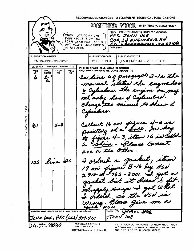


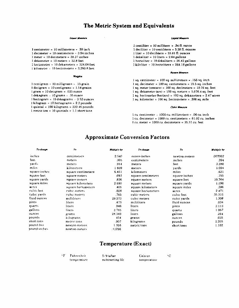

P I N : 0 6 9 0 5 1 - 0 0 4

This fine document...
Was brought to you by me:
Liberated Manuals -- free army and government manuals
Why do I do it? I am tired of sleazy CD-ROM sellers, who take publicly available information, slap “watermarks” and other junk on it, and sell it. Those masters of search engine manipulation make sure that their sites that sell free information, come up first in search engines. They did not create it... They did not even scan it... Why should they get your money? Why are not letting you give those free manuals to your friends?
I am setting this document FREE. This document was made by the US Government and is NOT protected by Copyright. Feel free to share, republish, sell and so on.
I am not asking you for donations, fees or handouts. If you can, please provide a link to liberatedmanuals.com, so that free manuals come up first in search engines:
<A HREF=http://www.liberatedmanuals.com/>Free Military and Government Manuals</A>
– SincerelyIgor Chudovhttp://igor.chudov.com/
– Chicago Machinery Movers