forsmark site investigation – bedrock geology – overview and
TRANSCRIPT

Svensk Kärnbränslehantering ABSwedish Nuclear Fueland Waste Management Co
Box 250, SE-101 24 Stockholm Phone +46 8 459 84 00
R-10-04
CM
Gru
ppen
AB
, Bro
mm
a, 2
010
Forsmark site investigation
Bedrock geology – overview and excursion guide
Michael B Stephens Geological Survey of Sweden
September 2010
Tänd ett lager:
P, R eller TR.
Forsmark site investigation
Bedrock geology – overview and excursion guide
Michael B Stephens Geological Survey of Sweden
September 2010
ISSN 1402-3091
SKB R-10-04
This report concerns a study which was conducted for SKB. The conclusions and viewpoints presented in the report are those of the author. SKB may draw modified conclusions, based on additional literature sources and/or expert opinions.
A pdf version of this document can be downloaded from www.skb.se.

R-10-04 3
Contents
1 Introduction 51.1 Background 51.2 Aim and scope 5
2 Regional geological setting 7
3 Bedrock geology at Forsmark 113.1 Rock groups, rock units, rock types and rock domains 113.2 Deformational and cooling history 193.3 Fracture domains 24
4 Excursion stops 274.1 Sources of information 274.2 Description of excursion stops 27
5 References 49
R-10-04 5
1 Introduction
1.1 BackgroundBetween 2002 and 2008, the Swedish Nuclear Fuel and Waste Management Company (SKB) carried out detailed site investigations at two locations in Sweden, Forsmark and Laxemar-Simpevarp, in order to identify suitable bedrock for the construction of a repository at approximately –500 m eleva-tion for the disposal of highly radioactive, spent nuclear fuel. During 2009, SKB decided to apply to the governmental authorities for a permit to construct a repository at the Forsmark site.
Geological mapping of the bedrock exposed at the ground surface was carried out during an early stage of each site investigation. These field data, together with airborne (helicopter) magnetic data, provided the basis for the construction of bedrock geological maps of the ground surface at each site, i.e. 2D geological models for the distribution of rock units on this surface.
The bedrock geological maps, together with data obtained from drilling activities down to approxi-mately –1,000 m elevation, subsequently provided the basis for the construction of 3D geological models for rock domains and fracture domains at Forsmark /Stephens et al. 2007/ and Laxemar-Simpevarp /Wahlgren et al. 2008/. The field data also provided a foundation for the choice of sample localities for mineralogical, geochemical and petrophysical analytical work, as well as for the choice of sites for drilling activities and for the detailed mapping of fractures at both Forsmark (see over-view in /Stephens et al. 2007/) and Laxemar-Simpevarp (see overview in /Wahlgren et al. 2008/). Furthermore, the field data provided a basis for the choice of sample localities for geochronological studies at both sites /Söderbäck (ed) 2008/. In summary, the field observations at the ground surface at each site have been of major importance for our understanding of the bedrock geology at depth at each site.
Bedrock mapping of the ground surface at Forsmark was carried out during two field campaigns during 2002 /Stephens et al. 2003a/ and 2003 /Bergman et al. 2004/. Bedrock geological maps, version 1.1 /SKB 2004/ and version 1.2 /SKB 2005/, respectively, were subsequently developed. The acquisition of high-resolution ground magnetic data and surface data from drilling activities in areas that lack out-crop resulted in minor modifications of the bedrock geological map version 1.2, and the presentation of revised versions of this map during model stages 2.2 /Stephens et al. 2007/ and 2.3 /Stephens et al. 2008a/. A complete description of the bedrock geological map of the ground surface at Forsmark was presented in /Stephens et al. 2008a/.
1.2 Aim and scopeBearing in mind the significance of the bedrock data from the ground surface for the geological 3D modelling work, SKB decided to present excursion guides that serve in the demonstration of the bedrock geology at the ground surface in both the Forsmark (this guide) and Laxemar-Simpevarp /Wahlgren 2010/ areas. An excursion guide is also available for the Olkiluoto area in south-western Finland /Paulamäki 2009/, which has been selected for the construction of a repository for the dis-posal of highly radioactive, spent nuclear fuel in Finland. The current excursion guide presents the bedrock geology and describes in detail the character of the bedrock at ten representative outcrops or outcrop areas at the ground surface in the site investigation area at Forsmark. All localities are located within or immediately adjacent to the proposed repository volume selected by SKB.

R-10-04 7
2 Regional geological setting
Forsmark is situated approximately 120 km north of Stockholm in the south-eastern part of Sweden (Figure 2-1a). A gentle relief and a landscape situated below the highest shoreline, which developed after the latest Quaternary glaciation, characterize the region around Forsmark (/Lidmar-Bergström 1994, Lundqvist 1994/ and Figure 2-1a). The bedrock surface beneath the unconsolidated, Quaternary glacial and post-glacial cover deposits, which is exposed only locally along the ground surface at Forsmark, corresponds to the morphological structure referred to as the sub-Cambrian peneplain /Lidmar-Bergström 1994/. This ancient denudation surface formed more than 540 million years ago. It corresponds geologically to a sub-Cambrian unconformity and marks a long period of uplift and erosion with loss of the geological record between the formation of the crystalline bedrock and the deposition of the unconsolidated Quaternary cover.
The bedrock at Forsmark is situated inside the Svecokarelian orogen in the south-western part of the Fennoscandian Shield (Figure 2-2a) which forms one of the ancient continental crustal fragments on the planet Earth. The Svecokarelian orogen is bordered by an Archaean continental nucleus to the north-east, by the Sveconorwegian orogen to the south-west and by Neoproterozoic and Phanerozoic sedimentary cover rocks of the East European Platform to the south-east (Figure 2-2a). In the west and north-west, it is overthrust by rocks that belong to the Caledonian orogen (Figure 2-2a). The thickness of the continental crust in the region that includes Forsmark is around 50 km.
Intrusive rocks, felsic volcanic rocks and subordinate sedimentary rocks, the majority of which were affected by pervasive or more localized ductile strain and metamorphism at mid crustal levels, dominate the Svecokarelian orogen in south-eastern Sweden /Koistinen et al. 2001/. Both the crystal-lization of the igneous rocks and the ductile deformation and metamorphism occurred between 1.9 and 1.8 Ga. Forsmark lies on the north-eastern periphery of one of Sweden’s important provinces for the exploitation of mineral deposits inside this orogen (Figure 2-1b), the so-called Bergslagen province /Stephens et al. 2009/. The abundant Fe oxide and Zn-Pb-Ag ± (Cu-Au) sulphide deposits along the arc-like structure to the west of Stockholm (Figure 2-1b) are hosted by felsic volcanic rocks dated at 1.91 to 1.89 Ga.
The Svecokarelian orogen in south-eastern Sweden has been divided into six tectonic domains (tectonic domains 1 to 6 in Figure 2-2b). These domains have been separated on the basis of differ-ences in either the timing of tectonic activity, i.e. the timing of ductile deformation, metamorphism and igneous activity, or in the character and intensity of the ductile strain /Hermansson et al. 2007, 2008a, Söderbäck (ed) 2008/. Forsmark is situated in tectonic domain 2 (Figure 2-2b).
Tectonic domain 2 contains broad belts of rocks that have been affected by strong ductile deforma-tion under amphibolite-facies metamorphic conditions. These ductile high-strain belts, which strike approximately WNW−ESE to NW−SE and are subvertical, anastomose around tectonic lenses in which the bedrock is commonly folded and, in general, affected by lower ductile strain (Figure 2-2c). They also contain retrograde deformation zones along which deformation occurred in both the ductile and brittle regimes (Figure 2-2c). The overall structural character of the bedrock in tectonic domain 2, in general, and in the Forsmark area, in particular, is strongly anisotropic. The volume at Forsmark targeted as a site for the disposal of highly radioactive spent nuclear fuel is situated in one of the tectonic lenses, the so-called Forsmark tectonic lens (Figure 2-2c).
A conceptual tectonic model for the Svecokarelian orogen in south-eastern Sweden has recently been proposed /Hermansson et al. 2008a, Söderbäck (ed) 2008/. This model envisages approximately northward-directed oblique subduction beneath an active continental margin to the north-east and a progressive migration of the subduction hinge away from or towards the overriding plate, related to long periods of transtensional tectonics and short periods of transpressional tectonics, respectively. This model highlights the accretionary rather than the continent-continent collisional character of the Svecokarelian orogen in the manner envisaged, for example, over 30 years ago by /Hietanen 1975/. The tectonic model is reminiscent of that occurring at the current time in the Andes, in the western part of South America, and in the northerly continuation of this Cordilleran mountain belt in the western part of North America.

8 R-10-04
Figure 2-1. Forsmark in a regional topographic and mineral resource perspective. (a) Digital relief map of Sweden based on the digital 50 m elevation database from Lantmäteriverket. Note the gentle relief in the Forsmark area. (b) Major mineral resource provinces in Sweden including the Bergslagen province. Figure after /Stephens et al. 2009/.
a b
Stockholm
Göteborg
Malmö
Forsmark
Laxemar-Simpevarp
© Sveriges geologiska undersökning
2100 m a s l
0
200 km
Skellefte districtVästerbottengold line
Norrbotten
Björkdal
Maurliden
Aitik
Kiirunavaara
Renström
Svartliden
Kristineberg Storliden
Malmberget
BlaikenSvärtträsk
Garpenberg
Zinkgruvan
Lovisagruvan
Bergslagen
Iron oxide
SulphideOther oxide
Precious metal
Iron oxideSulphidePrecious metal
Mine in operation
Deposit
Stockholm
Göteborg
Malmö
Forsmark
Laxemar-Simpevarp
© Sveriges geologiska undersökning

R-10-04 9
Figure 2-2. Regional geological setting of the Forsmark site. (a) Major tectonic units in the northern part of Europe at the current level of erosion (figure modified after /Koistinen et al. 2001/). The locations of Forsmark and Laxemar-Simpevarp as well as the proposed repository site at Olkiluoto in Finland are also shown on the map. (b) Svecokarelian tectonic domains and post-Svecokarelian rock units in the south-western part of the Fennoscandian Shield, south-eastern Sweden (figure modified after /Koistinen et al. 2001/). (c) Inferred high-strain belts and tectonic lenses, including the Forsmark tectonic lens, in the area close to Forsmark, all situated along a coastal deformation belt in the northern part of Uppland, Sweden (figure modified after /Stephens et al. 2007/).
Neoproterozoic and Phanerozoic cover sedimentary rocks and igneous rocksCaledonian orogen
Fennoscandian ShieldSveconorwegian orogenPost-Svecokarelian igneous and sedimentary rocksPalaeoproterozoic rocks in Blekinge–Bornholm tectonic beltPre-Svecokarelian rocks and rocks formed along Svecokarelian active continental margin (Palaeo–proterozoic). Younger dolerite dykes/sills not shown
Pre-Svecokarelian rocks (Palaeoproterozoic)
Archaean continental nucleus
Archaean continental nucleus – reworked
Rocks affectedby theSvecokarelianorogeny
Rocks little affected by theSvecokarelianorogeny
Oslo HelsinkiStockholm
Forsmark
Olkiluoto
Laxemar-Simpevarp
Figure2-2b
Tectonic domain 1
Tectonic domain 3
Tectonic domain 2
Tectonic domain 4
Tectonic domain 5
Tectonic domain 6
Ljusdal
Västervik
Vetlanda
Kalmar
Lower Palaeozoic coversedimentary rocks
Sveconorwegian orogen
Neoproterozoic cover sedimentary rocks,dolerite
Post-Svecokarelian igneous and sedimen-tary rocks. Palaeoproterozoic (<1.7 Ga)and Mesoproterozoic in age
Svecokarelian orogen with Palaeopro-terozoic (1.91–1.75 Ga) rocks formedalong migratory active continental margin.Younger dolerite dykes/sills not shown
Tectonic domains in Svecokarelian orogenwith ductile, high-strain belts that strikeWNW-ESE and anastomose around tectonic lenses with lower strain
Bergslagen region
Palaeoproterozoic rocks in Blekinge-Bornholm tectonic belt
Forsmark
Öland
Gotland
0 50 100 km
Laxemar-SimpevarpLaxemar-Simpevarp
Fennoscandian Shield
StockholmStockholm
a b
Figure2-2c
0 5 10 km
Area inferred to be affected by higher ductile strainArea inferred to be affected by lower ductile strain(tectonic lens)
Major, retrograde deformation zone (DZ) along the coast (1 = Singö DZ, 2 = splay from Singö DZ, 3 = Eckarfjärden DZ,4 = Forsmark DZ)
1
Forsmark tectonic lens (land, left; under sea, right)
Sea, lake
Candidate area for site investigation work at Forsmark
Österbybruk
Öregrund
Öregrundsgrepen
Kallrigafjärden
Gräsö
Gimo
Forsmarknuclearpower plant
1
2
34
SFR
Östhammar
Hargshamn
c
10 R-10-04
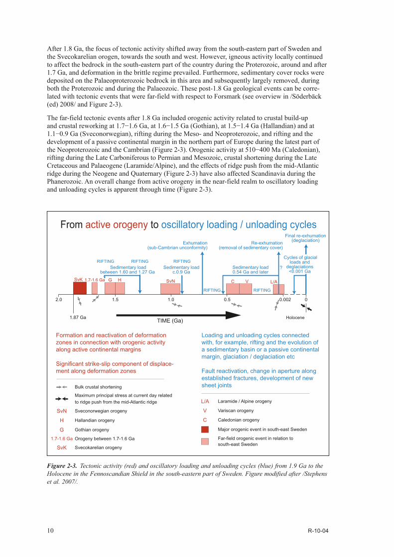
After 1.8 Ga, the focus of tectonic activity shifted away from the south-eastern part of Sweden and the Svecokarelian orogen, towards the south and west. However, igneous activity locally continued to affect the bedrock in the south-eastern part of the country during the Proterozoic, around and after 1.7 Ga, and deformation in the brittle regime prevailed. Furthermore, sedimentary cover rocks were deposited on the Palaeoproterozoic bedrock in this area and subsequently largely removed, during both the Proterozoic and during the Palaeozoic. These post-1.8 Ga geological events can be corre-lated with tectonic events that were far-field with respect to Forsmark (see overview in /Söderbäck (ed) 2008/ and Figure 2-3).
The far-field tectonic events after 1.8 Ga included orogenic activity related to crustal build-up and crustal reworking at 1.7−1.6 Ga, at 1.6−1.5 Ga (Gothian), at 1.5−1.4 Ga (Hallandian) and at 1.1−0.9 Ga (Sveconorwegian), rifting during the Meso- and Neoproterozoic, and rifting and the development of a passive continental margin in the northern part of Europe during the latest part of the Neoproterozoic and the Cambrian (Figure 2-3). Orogenic activity at 510−400 Ma (Caledonian), rifting during the Late Carboniferous to Permian and Mesozoic, crustal shortening during the Late Cretaceous and Palaeogene (Laramide/Alpine), and the effects of ridge push from the mid-Atlantic ridge during the Neogene and Quaternary (Figure 2-3) have also affected Scandinavia during the Phanerozoic. An overall change from active orogeny in the near-field realm to oscillatory loading and unloading cycles is apparent through time (Figure 2-3).
Figure 2-3. Tectonic activity (red) and oscillatory loading and unloading cycles (blue) from 1.9 Ga to the Holocene in the Fennoscandian Shield in the south-eastern part of Sweden. Figure modified after /Stephens et al. 2007/.
RIFTING RIFTING
TIME (Ga)
HSvK SvN C V L/AG
1.87 Ga
2.0 1.5
1.7-1.6 Ga
1.0 0.5 00.002
Holocene
Final re-exhumation(deglaciation)Re-exhumation
(removal of sedimentary cover)
Sedimentary load0.54 Ga and later
Sedimentary loadc.0.9 Ga
Sedimentary loadbetween 1.60 and 1.27 Ga
Exhumation(sub-Cambrian unconformity)
?
SvN Sveconorwegian orogeny
Bulk crustal shortening
Maximum principal stress at current day relatedto ridge push from the mid-Atlantic ridge
H Hallandian orogeny
G Gothian orogeny
1.7-1.6 Ga Orogeny between 1.7-1.6 Ga
SvK Svecokarelian orogeny
L/A Laramide / Alpine orogeny
V Variscan orogeny
C Caledonian orogeny
Major orogenic event in south-east Sweden
Far-field orogenic event in relation tosouth-east Sweden
RIFTING RIFTING RIFTING Cycles of glacial
loads anddeglaciations
<0.001 Ga
Formation and reactivation of deformationzones in connection with orogenic activity along active continental margins
Significant strike-slip component of displace-ment along deformation zones
Loading and unloading cycles connectedwith, for example, rifting and the evolution ofa sedimentary basin or a passive continentalmargin, glaciation / deglaciation etc Fault reactivation, change in aperture alongestablished fractures, development of newsheet joints
From active orogeny to oscillatory loading / unloading cycles

R-10-04 11
3 Bedrock geology at Forsmark
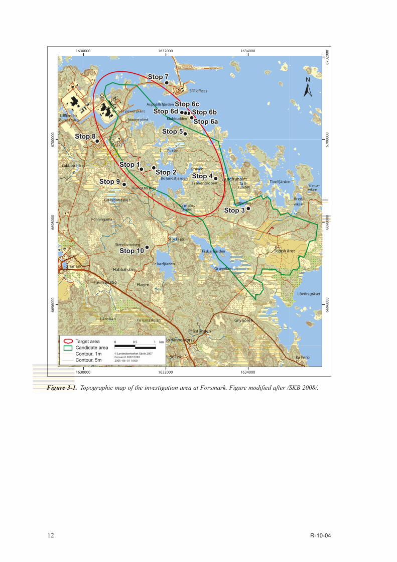
In order to place the excursion stops in a local geological perspective, a description of the rock components, the deformational and cooling history and the fracture domains at the Forsmark site is provided below. For a more detailed description of the bedrock geology and the bedrock geological evolution of the Forsmark area, the reader is referred to /Stephens et al. 2007, Söderbäck (ed) 2008, SKB 2008/ and references therein. The topography and place names in the Forsmark area are shown in Figure 3-1 and a bedrock geological map of the investigation area at the ground surface is presented in Figure 3-2. A more detailed bedrock geological map and a magnetic anomaly map of the north-western part of the ground investigation area at Forsmark, inside the proposed repository volume, are shown in Figure 3-3 and Figure 3-4, respectively.
3.1 Rock groups, rock units, rock types and rock domains Four major groups of rocks (Groups A to D), distinguished on the basis of their relative age relation-ships, are present in the Forsmark area (Table 3-1). One or more rock units, which are distinguished on the basis of the character of the dominant rock type, are included in each group (Table 3-1). Rock types within each unit are distinguished on the basis of their composition, grain size and relative age. The bedrock geological map of the Forsmark area shows a 2D model for the spatial distribution of the different rock units at the ground surface in this area (Figure 3-2 and Figure 3-3).
Bedrock where the rocks are banded and/or affected by a strong, ductile tectonic foliation (black dots present in Figure 3-2 and Figure 3-3) have also been distinguished from bedrock where the rocks are folded and more lineated in character (black dots absent in Figure 3-2 and Figure 3-3). The former are inferred to be affected by higher ductile strain and anastomose around the more folded and line-ated bedrock with lower ductile strain inside several tectonic lenses /Stephens et al. 2008a/. The pro-posed repository volume at Forsmark, between Lake Bolundsfjärden and the nuclear power plant, is situated inside the north-western part of one of these tectonic lenses, referred to here as the Forsmark tectonic lens (see Figure 3-2). For 3D modelling purposes, the bedrock has also been divided into different rock domains /Stephens et al. 2007/. A rock domain refers to a rock volume in which rock units that show similar composition, grain size, degree of bedrock homogeneity, and degree and style of ductile deformation have been combined.
The bedrock at Forsmark is dominated by meta-intrusive rocks that formed between 1.89 and 1.86 Ga (Group B) and between 1.86 and 1.85 Ga (Groups C and D), respectively (/Hermansson et al. 2007, 2008a, Stephens et al. 2008a/, Table 3-2 and Figure 3-5). A critical feature of all the more acid rocks in these two suites is their high content of quartz (Figure 3-6). The Group B meta-intrusive rocks consist of granitoids as well as subordinate ultrabasic, basic and intermediate rocks, metamorphosed under amphibolite-facies conditions. The rocks in the subordinate Groups C and D consist solely of granitoids that show a lower degree of metamorphism. The two suites have been distinguished primarily on the basis of their relationships to the penetrative ductile deformation in the area /Stephens et al. 2008a/. The older suite was affected by a penetrative ductile grain-shape fabric, with both planar and linear components, and by folding, while the younger suite intruded during the later stages of or after the development of the ductile fabric and generally shows a linear or poorly developed grain-shape fabric. Both suites intruded into supracrustal rocks dominated by acid metavolcanic rock (Group A). The bedrock volume that hosts the proposed repository is dominated by metamorphosed, biotite-bearing granite (to granodiorite) that belongs to the older Group B suite (SKB code 101057).
12 R-10-04
Figure 3-1. Topographic map of the investigation area at Forsmark. Figure modified after /SKB 2008/.
viken
Ta ll−sundet
Graven
Puttan
Länsöån
Länsöån
�ärden
Norrsjön
Gruvviken
Stocks jön
n
Gunnarsbo−
Fo rsmarksån
Li llfjärden
Lövörsgräset
Ec karfjärden
Kungsträsk etFr äkengropen Tixe lfjärden
Labboträsk et
Fi sk ar�ärden
Gällsboträske t
Bo lundsfjärden
Hagen
So lvik Ka llerö
Gr ynören
Fo rsmark
Hermansbo
Habbal sb o
Pr ästängen
St orsk äret
Jo hannes fors
Sewage plant
Nuclea r power plant
Ju ngfruholm
Asphälls�ärden
Vambörs−
Simp−
Bred−
viken
Li llfjärdenKlubbudden
SFR o�ces
Rönningarna
Stenrösmossen
1630000 1632000 1634000
6696
000
6698
000
6700
000
6702
000
Stop 6a
Stop 2
Stop 6a
Stop 1Stop 4
Stop 5
Stop 6bStop 6c
Stop 6d
Stop 8
Stop 9
Stop 7
Stop 3
Stop 10
Stop 1Stop 2 Stop 4
Stop 5
Stop 6bStop 6c
Stop 6d
Stop 8
Stop 9
Stop 7
Stop 3
Stop 10
1630000 1632000 163400066
9600
066
9800
067
0000
0
10 0.5 km
© Lantmäteriverket Gävle 2007Consent I 2007/10922005−06−01 10:00
Target areaCandidate areaContour, 1mContour, 5m

R-10-04 13
1630000
1630000
1632000
1632000
1634000
1634000
1636000
1636000
6696
000
6696
000
6698
000
6698
000
6700
000
6700
000
6702
000
6702
000
!?!?!?
!?
!?
!?
!?
!?
!?
!?
!?
!?
!?
!?!?
!?
!?
!?
!?
!?
!?!?
!?
!?
!?
!?
!?
!?
!?
!?!?
!?
!?
!?
!?!?
!?
!?
!.
!.
!.
!.!.
!.
!.!.
!.
!.
!.
!.!.!.
!.
!. !.!.
!.
!.!.
!.
!.
!.
!.
!.
±0 1 20.5 km
© Lantmäteriverket Gävle 2007Consent I 2007/10922007-04-26 16:00
BoreholesCored borehole with horizontal projection (1A–12A)Percussion borehole (1–38)
Brittle and low-temperature ductile deformation
Regional deformation zone
Banded and/or strongly foliatedbedrock (strong ductile deformation)
Abandoned mine or exploration prospectMagnetite mineralisation
Dominant rock typeGranite, fine- to medium- grainedPegmatite, pegmatitic granite
Granite, granodiorite and tonalite, metamorphic,fine- to medium- grained
Granite to granodiorite, metamorphic, veinedto migmatitic, medium-grained
Granite, metamorphic, aplitic
Granite to granodiorite, metamorphic, medium grainedGranodiorite, metamorphicTonalite to granodiorite, metamorphicDiorite, quartz diorite and gabbro, metamorphicUltramafic rock, metamorphicMagnetite mineralisation associated withcalc-silicate rock (skarn)Felsic to intermediate volcanicrock, metamorphic
Other ornamentsCoastline
Tunnel from nuclear power plant
SFR including access tunnels
RoadTarget areaBuilding
Group D
Group C
Group B
Group A
Klubbudden
Asphällsfjärden
Bolundsfjärden
Klubbudden
High temperature ductile deformation
Eckarfjärden deformation zone
Singö deformation zone
Forsmark deformation zone
Eckarfjärden deformation zone
Singö deformation zone
Forsmark deformation zone
Enlarged area in thegeological map above
Forsmark tectonic lens
Stop 1Stop 2 Stop 4
Stop 5Stop 6aStop 6b
Stop 6cStop 6d
Stop 8
Stop 9
Stop 1Stop 2 Stop 4
Stop 5Stop 6aStop 6b
Stop 6cStop 6d
Stop 8
Stop 9
Stop 7Stop 7
Stop 3Stop 3
Stop 10Stop 10
Fig. 3-3Fig. 3-3
Figure 3-2. Bedrock geological map of the investigation area at Forsmark. Figure modified after /SKB 2008/.

14 R-10-04
Cored borehole
Percussion borehole
Borehole projection
Outcrop
Brittle and low-temperature ductile deformation
Gently dipping deformation zone
Steeply dipping deformation zone (>3,000 m at ground surface)
Cataclastic rock, hydrothermally altered rock
Mylonitic rock
High-temperature ductile deformationBanded and/or strongly foliated bedrock (strong ductile deformation)
Form line, banding
Form line, foliation
Banding, strike/dip
Banding, strike/vertical dip
Foliation, strike/dip
Foliation, strike/vertical dip
Mineral lineation, trend/plunge
Fold axis, trend/plunge
Key mineral
Epidote
Garnet
Hematite
Chlorite
Hydrothermal quartz
Magnetite
Other ornaments
Coastline
Road
SFR including access tunnels
Tunnel from nuclear power plant
Building
Dominant rock typeGroup D
Granite, fine- to medium-grained
Pegmatite, pegmatitic granite
Group CGranite, granodiorite and tonalite, metamorphic, fine- to medium-grained
Group B
Granite, metamorphic, aplitic
Granite to granodiorite, metamorphic, medium-grained
Granodiorite, metamorphic
Tonalite to granodiorite, metamorphic
Diorite, quartz diorite and gabbro, metamorphic
Group A
Felsic to intermediate volcanic rock, metamorphic
Subordinate rock typeGroup D
Leucocratic granite dyke
Pegmatite/pegmatitic granite dyke
Pegmatite/pegmatitic granite as band, lens or segregation
Group CFine- to medium-grained metagranitoid as dyke or smaller massif
Group B
Amphibolite as band, lens, enclave, inclusion or dyke
Medium-grained metagranitoid as band, lens, enclave,inclusion or dyke
Metamorphosed diorite/quartz diorite/gabbro as band, lens, enclave or inclusion
Metamorphosed ultramafic rock as band, lens, enclaveor inclusion
Group A
Calc-silicate rock as band or lens in metavolcanic rock
Calc-silicate rock as xenolith
Felsic to intermediate metavolcanic rock as xenolith
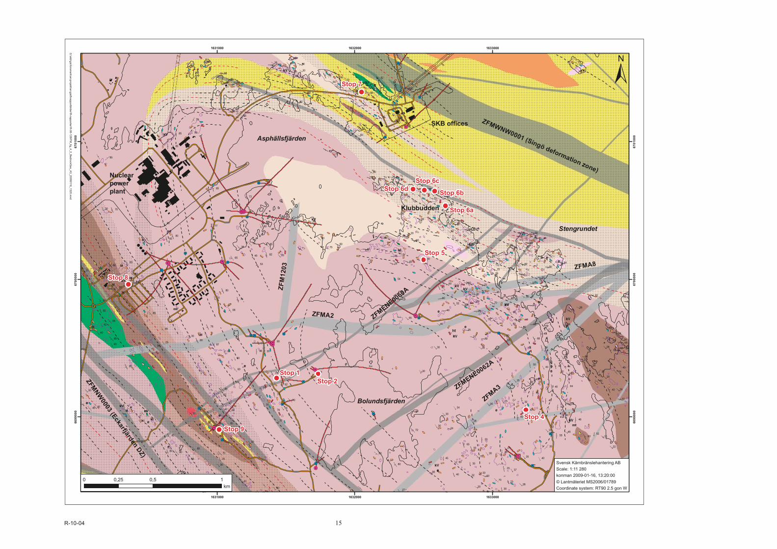
Figure 3-3. Detailed bedrock geological map of the north-western part of the investigation area at Forsmark inside the proposed repository volume. Figure modified after /Stephens et al. 2008a/.
R-10-04 15
82
60
86
80
70
70
82
35
50
55
40
35
40
28
15
22
26
16
20
38
34
24
33
23
37
21
30
32
34
30
30
3024
28
30
32
30
35
53
37
40
30
50
2030
3618
38
50
40
26
40
28
36
50
56
80
82
44
22
72
58
75
62
52
48
54
6578
40
2571
80
78
82
80
78
74
80
85
8580
85
72
8075
80
80
82
53
65
77
70
55
68
62
8040
40
72
80
82
87
80
85
85
85
85
45
64
60
40
55
45
50
38
40
40
50
45
78
72
40
85
88
80
80
78
84
708482
65
86
88
85
85
82
76
75
80
75
35
34
55
80
28
25
28
30
30
30
32
3028
55
30
33
2830
20
85
50
30
38
30
20
30
45
5050
30
40
25
10
35
45
40
2540
42
30
50
45
20
30
30
30
30
25
40
40
50
32
30
35
35
45
5245
40
30
45
55
40
40
52
45
40
80
65
65 75
60
38
70
80
82
75
82
80
80
80
80
75
6070
40
60
72
88
86
88
79
59
70
80
85
68
85
60
27
80
80
85
85
72
78
78
82
80
54
80
80
80
85
85
70
85
80
80
40
85
70
80
40
60
85
85
85
85
85
80
7575
80
85
85
85
70
80
84
85
85
80
86
80
64
46
6055
50
85
8580
50
72
87
80
75
74
25
6535
60
60
45
65
55
8070
72
1631000
1631000
1632000
1632000
1633000
1633000
6699
000
6699
000
6700
000
6700
000
6701
000
6701
000
0 0,5 10,25km
Svensk Kärnbränslehantering AB Scale: 1:11 280konman 2009-01-16, 13:20:00© Lantmäteriet MS2006/01789Coordinate system: RT90 2.5 gon W
Asphällsfjärden
Stengrundet
Bolundsfjärden
Klubbudden
Nuclear power plant
ZFMWNW0001 (Singö deformation zone)
ZFMNW0003 (Eckarfjärden DZ)
ZFM
1203
ZFMA2 ZFMENE0060A
ZFMA8
ZFMENE0062A
ZFMA3
G:\skb\gis\forsm
ark\arcprojekt\arcgis8\rapportbilder\R-rapporter\R
-08-128\FM_fig_4_2_B
edrockGeo_A
3_20090116_1320.mxd
SKB offices
Stop 1Stop 2
Stop 4
Stop 5
Stop 6a
Stop 6b
Stop 6cStop 6d
Stop 8
Stop 9
Stop 1Stop 2
Stop 4
Stop 5
Stop 6a
Stop 6b
Stop 6cStop 6d
Stop 8
Stop 9
Stop 7Stop 7
R-10-04 17
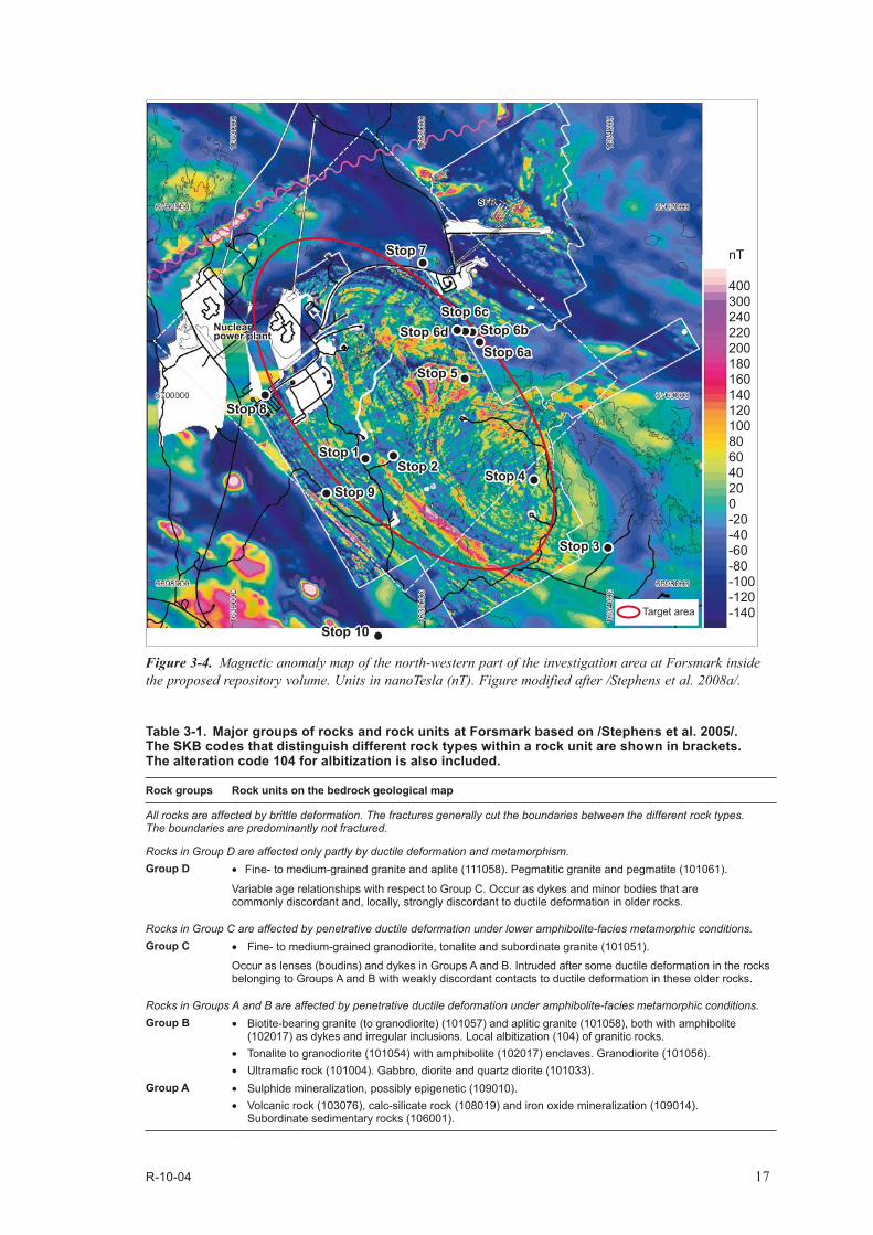
Figure 3-4. Magnetic anomaly map of the north-western part of the investigation area at Forsmark inside the proposed repository volume. Units in nanoTesla (nT). Figure modified after /Stephens et al. 2008a/.
Target area
Nuclearpower plantNuclearpower plant
SFRSFR
Stop 1Stop 2
Stop 4
Stop 5Stop 6aStop 6b
Stop 6cStop 6d
Stop 8
Stop 9
Stop 1Stop 2
Stop 4
Stop 5Stop 6aStop 6b
Stop 6cStop 6d
Stop 8
Stop 9
Stop 7Stop 7
Stop 3Stop 3
Stop 10Stop 10
nT
400300240220200180160140120100806040200-20-40-60-80-100-120-140
Table 3-1. Major groups of rocks and rock units at Forsmark based on /Stephens et al. 2005/. The SKB codes that distinguish different rock types within a rock unit are shown in brackets. The alteration code 104 for albitization is also included.
Rock groups Rock units on the bedrock geological map
All rocks are affected by brittle deformation. The fractures generally cut the boundaries between the different rock types. The boundaries are predominantly not fractured.
Rocks in Group D are affected only partly by ductile deformation and metamorphism.Group D • Fine- to medium-grained granite and aplite (111058). Pegmatitic granite and pegmatite (101061).
Variable age relationships with respect to Group C. Occur as dykes and minor bodies that are commonly discordant and, locally, strongly discordant to ductile deformation in older rocks.
Rocks in Group C are affected by penetrative ductile deformation under lower amphibolite-facies metamorphic conditions.Group C • Fine- to medium-grained granodiorite, tonalite and subordinate granite (101051).
Occur as lenses (boudins) and dykes in Groups A and B. Intruded after some ductile deformation in the rocks belonging to Groups A and B with weakly discordant contacts to ductile deformation in these older rocks.
Rocks in Groups A and B are affected by penetrative ductile deformation under amphibolite-facies metamorphic conditions.Group B • Biotite-bearing granite (to granodiorite) (101057) and aplitic granite (101058), both with amphibolite
(102017) as dykes and irregular inclusions. Local albitization (104) of granitic rocks. • Tonalite to granodiorite (101054) with amphibolite (102017) enclaves. Granodiorite (101056). • Ultramafic rock (101004). Gabbro, diorite and quartz diorite (101033).
Group A • Sulphide mineralization, possibly epigenetic (109010).• Volcanic rock (103076), calc-silicate rock (108019) and iron oxide mineralization (109014).
Subordinate sedimentary rocks (106001).
18 R-10-04
Table 3-2. Age of crystallisation of the igneous rocks in the Forsmark area based on /Page et al. 2004, Hermansson et al. 2007, 2008a/. TIMS = Thermal Ionisation Mass Spectrometry technique. SIMS = Secondary Ion Mass Spectrometry technique.
Geological feature Dated rock type Method Age
Younger dykes and intrusions with granitic composition (Group D intrusive rocks).
Granite. U-Pb zircon (SIMS) 1851 ±5 Ma 1855 ±6 MaAge supported by the U-Pb titanite age of 1844 ±4 Ma from the same rock type.
Younger dyke-like bodies and minor intrusions with granodioritic to tonalitic composition (Group C intrusive rocks).
Metagranodiorite. U-Pb zircon (SIMS) 1864±4 Ma
Younger dyke-like bodies and irregular minor intrusions with basic composition (amphibolite) in Group B metagranite.
− − Age of intrusion inferred to be 1.87−1.86 Ga, based on U-Pb (zircon) age of Group B metagranite and a regression age for the three older U-Pb (titanite) ages in amphibolite.
Older plutons with granitic composition (Group B intrusive rocks).
Metagranite inside the target area.
U-Pb zircon (SIMS) 1867±4 Ma
Older plutons with ultrabasic to intermediate, tonalitic and granodioritic compositions (Group B intrusive rocks).
Metatonalite to metagranodiorite-Metagabbro.
U-Pb zircon (SIMS)
U-Pb zircon (TIMS)
1883±3 Ma
1886±1 Ma
Supracrustal rocks (Group A). − − Age inferred to be older than 1885 Ma.
pumpellyite–prehnitelaumontite–prehnite
Rock fragmentin fault breccia (Bh)
Olderadularia (Bh)
Youngeradularia (Bh)
Tectonothermal disturbanceduring the Sveconorwegianorogeny at 1.1-0.9 Ga Post–Cambrian loading by sedimentary cover.
Exhumation of crystalline rocks prior to theQuaternary
Effects of Permianextensional tectonics
Greenschist facies
Sub–greenschist facies
Amphibolite facies
Age (million years)
Tem
pera
ture
(°C
)
U-Pb zircon
U-Pb titanite(550-700oC)
40Ar/39Ar amphibole(c.500oC)
40Ar/39Ar muscovite(c.350oC)40Ar/39Ar biotite(c.300oC)
40Ar/39Ar K-feldspar(c.200-225oC)
(U-Th)/Heapatite (c.70oC)
Rock-forming mineralFracture mineral
Sample at depth from borehole. Other samples are from the surfaceBh
Bh
Bh
Bh
2000 1750 1500 1250 1000 750 500 250 0
1.89-1.85 Ga igneous activity
Penetrative ductiledeformation, high-strainbelts, folding
Localised ductile strainalong zones
Age interval forchangeover toductile-brittleand brittledeformation atthe ground surface
SC/Bh KFM01A (0–500 m)SU/Bh KFM01A (0–500 m)
Selected and corrected (U–Th)/He ageSC
Selected and uncorrected (U–Th)/He ageSU
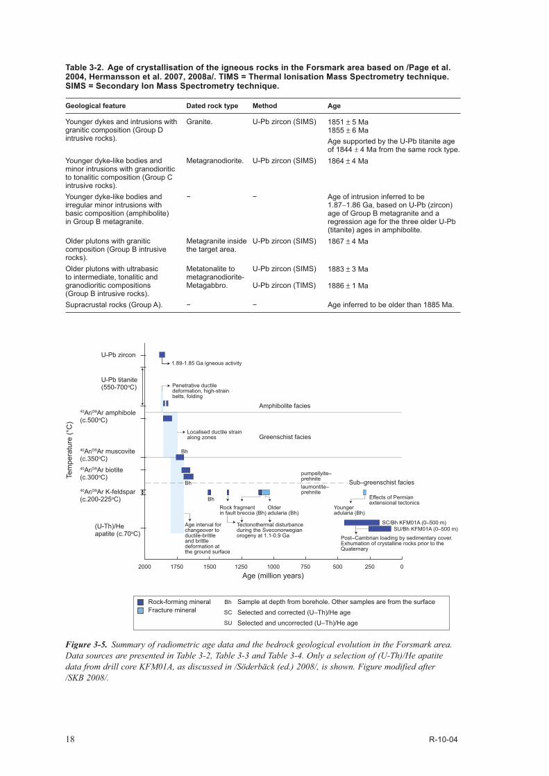
Figure 3-5. Summary of radiometric age data and the bedrock geological evolution in the Forsmark area. Data sources are presented in Table 3-2, Table 3-3 and Table 3-4. Only a selection of (U-Th)/He apatite data from drill core KFM01A, as discussed in /Söderbäck (ed.) 2008/, is shown. Figure modified after /SKB 2008/.

R-10-04 19
3.2 Deformational and cooling history The rocks in the Forsmark area display evidence for a protracted ductile deformational history, with the development of a penetrative fabric under amphibolite-facies conditions between 1.87 and 1.86 Ga, followed by folding on different scales (/Hermansson et al. 2007, 2008a, Stephens et al. 2008a/, Figure 3-3, Figure 3-4 and Figure 3-5). The rocks inside the Forsmark tectonic lens display a predominantly linear grain-shape fabric and folds that plunge moderately to the south-east. The folding rotated a subordinate, planar grain-shape fabric and, north-west of Asphällsfjärden (Figure 3-3), even a ductile high-strain belt /Stephens et al. 2008a/. By contrast, the rocks in the ductile high-strain belts that surround the Forsmark tectonic lens show a generally more intense planar and linear grain-shape fabric, and the compositionally more heterogeneous rock units occur as striped gneisses /Stephens et al. 2008a/. Rock contacts and the planar structures in these belts are vertical or dip steeply to the south-south-west to south-west (Figure 3-3) and both the mineral stretching lineation and fold axes plunge moderately or gently to the south-east /Stephens et al. 2008a/. Field evidence for a dextral strike-slip component of movement prior to folding has locally been observed /Stephens et al. 2008a/.
During the time interval between 1.85 and 1.8 Ga, the Forsmark area is inferred to have remained at temperatures around 500°C and the area was uplifted above the 500°C geotherm at 1.8 Ga (Table 3-3 and Figure 3-5). During this time interval, ductile deformation occurred under lower grade meta-morphic conditions within the ductile high-strain belts but along more spatially constrained zones /Stephens et al. 2008a/. Regionally significant structures, with a trace length greater than 10 km at the current ground surface, include the Forsmark, Eckarfjärden and Singö deformation zones (Figure 3-2). Protomylonites and mylonites developed along these vertical or steeply dipping zones with WNW−ESE or NW−SE strike, locally with evidence again for dextral strike-slip displacement /Stephens et al. 2008a/. Cooling beneath the 300°C geotherm and the establishment of sub-greenschist
Figure 3-6. QAP(F=0) modal classification of all the analysed intrusive rock samples at the Forsmark site (Groups B, C and D), both from the surface and from boreholes. The classification is based on /Streckeisen 1976/. Groups B, C and D are defined in Table 3-1. Nearly 70% of the borehole samples shown on this diagram come from the local model volume. By contrast, there is no such focus for the surface samples; over 75% of these samples lie outside the local model volume. Notwithstanding this discrepancy, the trends are identical in both sample sets. Figure after /SKB 2008/.
100
90
90
90
80
80
80
70
70
70
60
60
60
50
50
50
40
40
40
30
30
30
20
20
20
10
10
10
100
Alkalifeldspar (A)
Plagioclasefeldspar (P)
Quartz (Q)
TonaliteGrano-diorite
Granite
(syeno-granite)
Quartz Quartzsyenite
Syenite Monzonite
monzonite
(monzo-granite)
Quartz monzodioriteQuartz monzogabbro
MonzodioriteMonzogabbro Quartz diorite
Quartz gabbroQuartz anorthosite
DioriteGabbroAnorthosite
Group DGroup C Borehole
sampleGroup B
Surface sampleField that containsaltered Group B rocks

20 R-10-04
metamorphic conditions occurred around 1.7 Ga (Table 3-3 and Figure 3-5). The bedrock could have started to deform in the brittle regime some time between 1.8 and 1.7 Ga, during the latest part of the Svecokarelian orogeny /Söderlund et al. 2009/. Cooling beneath the c. 225−200°C geotherm occurred between 1.6 and 1.5 Ga (Table 3-3 and Figure 3-5).
Apart from retrograde deformation in the brittle regime along the regionally significant, composite ductile and brittle, WNW−ESE or NW−SE deformation zones that surround the Forsmark tectonic lens, three other sets of brittle zones are prominent inside the lens (Figure 3-3 and /Stephens et al. 2007/). However, the latter show trace lengths at the ground surface generally less than 3 km and are more local in character relative to the regionally significant zones that surround the lens (Figure 3-3).
The two more significant local structures inside the Forsmark tectonic lens strike ENE−WSW to NNE−SSE and are steeply or gently dipping fracture zones, respectively. The steeply dipping set of fracture zones are conspicuous inside the proposed repository volume, in the area around Bolunds -fjärden (Figure 3-3 and /Stephens et al. 2007/), and are dominated by sealed fractures and prominent wall-rock alteration in the form of hematization. They have been identified with the help of magnetic data (Figure 3-4). By contrast, the gently dipping zones are prominent outside the proposed reposi-tory volume, to the south-east of Bolundsfjärden, where the ductile fabric flattens and dips gently toward the south-east /Stephens et al. 2007/. This observation suggests that the brittle deformation has been guided by the pre-existing ductile grain of the host rock /Stephens et al. 2007/. The gently
Table 3-3. Cooling ages in the Forsmark area based on /Page et al. 2004, 2007, Hermansson et al. 2007, 2008a, 2008b, Söderlund et al. 2008, 2009/.
Geological feature Dated rock type Method Age
Cooling below c 70°C. Group B metagranite to metagranodiorite. Surface samples and samples from KFM01A, KFM02A and KFM03A.
(U-Th)/He apatite Surface samples: FT-corrected ages are predominantly c 750 to 500 Ma. Uncorrected ages are predominantly c 500 to 300 Ma.Drill core samples: FT-corrected ages are predominantly c 700 to 200 Ma. Uncorrected ages are predominantly c 550 to 100 Ma. Decreasing age with depth in KFM01A and KFM03A. Poorly reproducible ages in especially KFM02A.
Minimum age for cooling below c 225−200°C.
Group B metagranite in KFM06B (near top) and KFM06A (near base).
40Ar/39Ar K-feldspar 1.55−1.49 Ga
Cooling below c 300°C. Various Group B and Group C acid meta-intrusive rocks, amphibolite. Surface and drill core samples.
40Ar/39Ar biotite Surface samples: Range from 1.73−1.66 GaDrill core samples: Ages in the upper parts of boreholes range from 1.71−1.68 Ga. Ages in the lower parts of boreholes, at c –1,000 m elevation, range from 1.68−1.63 Ga.
Cooling below c 350°C. Muscovite-bearing rock affected by strong ductile deformation in KFM04A.
40Ar/39Ar muscovite 1.76−1.71 Ga
Cooling below c 500°C. Amphibolite and metagabbro (surface samples).
40Ar/39Ar hornblende Ages between 1.86 and 1.80 Ga occur in the rock affected by a lower degree of ductile deformation inside the tectonic lenses. Only ages between 1.81 and 1.79 Ga occur in the rock affected by a higher degree of ductile deformation.
Cooling below 700−500°C.
Group D granite (surface sample).
U-Pb titanite (TIMS) 909±200 Ma (lower intercept age) 1,844±4 Ma (upper intercept age)
Amphibolite (surface samples).
U-Pb titanite (TIMS) 1,840±2 Ma to 1,832±3 Ma (207Pb/206Pb ages, pale brown or brown titanites)1,854±3 Ma (upper intercept age) 1,858±2 Ma (upper intercept age) 1,858±3 Ma (207Pb/206Pb age, olive-brown titanite) 1,860±2 Ma (207Pb/206Pb age, olive-brown titanite)

R-10-04 21
dipping zones contain a higher frequency of open fractures and incoherent crush material relative to the other sets, commonly bear groundwater in the current hydrogeological regime /Follin 2008, Follin et al. 2008/ and have been identified with the help of reflection seismic data /Juhlin and Stephens 2006/. Subvertical, NNW−SSE oriented fracture zones form a third set of fracture zones inside the Forsmark tectonic lens but, on the basis of their low frequency of occurrence, are of lower significance.
Fracture mineralogical data have provided an important tool to constrain the brittle deformational history of the Forsmark site and four generations of fracture minerals have been identified /Sandström et al. 2008, 2009/. The occurrence of different minerals along different fracture orientation sets has been addressed in both the more highly strained bedrock along deformation zones /Stephens et al. 2007, 2008b/ and in the bedrock between these zones /Sandström et al. 2008, 2009/.
The first generation of fracture minerals (generation 1) consists of epidote, quartz and chlorite. The wall-rock to the fractures that contain this generation of minerals is altered and shows a red staining with fine-grained hematite dissemination. The key mineral epidote occurs along cataclastic faults (Figure 3-7a) that formed during ductile to brittle conditions and along fractures with solely brittle deformation, all of which are either steeply dipping with an approximately NW−SE strike or are gently dipping. Epidote is also present along fractures in the other steeply dipping sets that strike approximately NE−SW (with ENE−WSW and NNE−SSW sub-sets) and NNW−SSE. On the basis of these observations and the 40Ar-39Ar dating of generation 2, hematite-stained adularia (Table 3-4), /Sandström et al. 2008, 2009/ and /Söderbäck (ed) 2008/ inferred precipitation of generation 1 minerals between 1.8 and 1.1 Ga, in particular during the late Svecokarelian orogenic stage at 1.8−1.7 Ga, when brittle conditions of deformation started to prevail. Rb-Sr dating of epidote along fractures in the surrounding region, south of Forsmark, has yielded ages in the time interval 1.6 to 1.5 Ga /Wickman et al. 1983/.
The second generation of fracture minerals (generation 2) is a sequence of hydrothermal minerals that consists of an early phase of hematite-stained adularia, albite and calcite, followed by prehnite and calcite (Figure 3-7b), and a late phase of hematite-stained laumontite, calcite and chlorite/corrensite. Once again, the wall-rock to the fractures that contain this generation of minerals is altered and shows a red staining with fine-grained hematite dissemination. The generation 2 minerals are associated solely with brittle deformation in the bedrock, commonly along sealed fractures. Laumontite-sealed and calcite-sealed breccias are also present (Figure 3-7c). The key minerals hematite-stained adularia and laumontite seal and coat steeply dipping fractures that strike approximately NE−SW and NNW−SSE. However, they are also present along fractures in the other steeply dipping set with approximately NW−SE strike and along gently dipping fractures.
On the basis of 40Ar-39Ar dating of generation 2 adularia and K-feldspar from rock fragments in laumontite- and calcite-sealed breccias (Table 3-4), it has been inferred that the generation 2 adularia formed either during the early part of the Sveconorwegian orogeny or prior to this complex tectonic event /Sandström et al. 2008, 2009, Söderbäck (ed) 2008/. The second of these hypotheses involved a Sveconorwegian resetting of the argon isotope system after precipitation of adularia along fractures, in combination with a less pervasive, Sveconorwegian resetting of the same isotope system in K-feldspar in the surrounding bedrock (Figure 3-5). Other geochronological data at Forsmark (/Hermansson et al. 2007/ and Table 3-3) confirm the significance of Sveconorwegian tectonic activity in the area.
The third generation of fracture minerals (generation 3) is dominated by euhedral quartz, calcite and pyrite (Figure 3-7d), together with subordinate corrensite, analcime, euhedral adularia that lacks hematite staining, other sulphide minerals, barite and fluorite. Oily asphaltite is also present, predominantly in the upper parts of drill cores (Figure 3-7e). No red staining in the wall rock formed in connection with the precipitation of the generation 3 minerals. The generation 3 minerals are associated solely with brittle deformation in the bedrock and occur along both sealed and open fractures. Generation 3 pyrite and asphaltite are conspicuous along NE−SW steep fractures, along gently dipping or subhorizontal fractures, particularly at an elevation above approximately –150 m, and along fractures in the other steeply dipping sets /Sandström et al. 2008/.

22 R-10-04
f
dc
ba
e
asphaltite
epidote
Figure 3-7. Drill core photographs showing fracture minerals in the four different generations recognised at Forsmark (figure after /SKB 2008/). (a) Generation 1. Epidote-bearing cataclasite (KFM06A, 268.77–268.82 m, /Sandström and Tullborg 2005/). (b) Generation 2. Fracture filled by brick-red, hematite-stained adularia cut by a fracture filled with prehnite (KFM05A, 689.33–689.61 m, /Sandström and Tullborg 2005/). (c) Generation 2. Laumontite-sealed breccia (KFM04A, 244.46–244.58 m, /Sandström and Tullborg 2005/). (d) Generation 3. Calcite and pyrite crystals on top of a fracture surface coated with quartz (KFM01A, 267.0 m, /Sandström et al. 2004/). (e) Generation 3. Asphaltite in voids in older, partly dissolved calcite along a steeply dipping fracture (KFM06A, 106.94–107.14 m, /Sandström and Tullborg 2005/). (f) Generation 4. Open fracture with a thin coating of calcite. This generation of calcite often occurs together with clay minerals (KFM08B, 97.37–97.43 m, /Sandström and Tullborg 2006/).

R-10-04 23
40Ar-39Ar dating of generation 3 adularia yielded a well-defined, Permian plateau age of 277 ± 1 Ma for one sample and a poorly-defined plateau for a second sample, inferred to provide a maximum age for the adularia of 456 ± 2 Ma (Table 3-4 and Figure 3-5). A Palaeozoic age for the generation 3 minerals is supported by the isotopic compositions of the associated minerals calcite, pyrite and oily asphaltite, which all indicate an organic influence in the fluid from which these minerals precipitated /Sandström et al. 2006a, 2008/. In particular, the asphaltite was derived from a Cambrian to Lower Ordovician black oil shale /Sandström et al. 2006a/ that, together with limestone and other clastic sedimentary rocks, covered the crystalline bedrock at Forsmark during much of the Phanerozoic (see below). Downward fluid flow from the Lower Palaeozoic sedimentary cover into fractures in the underlying crystalline bedrock has been perceived /Sandström et al. 2008, Söderbäck (ed) 2008/.
The fourth and youngest generation of fracture minerals consists of clay minerals and calcite with subordinate pyrite and goethite. As for the generation 3 minerals, no red staining in the wall rock formed in connection with the precipitation of these minerals. The generation 4 minerals coat open fractures (Figure 3-7f), either as the outermost mineral layer or as a single layer, and occur along brittle structures that are hydraulically conductive at the current time. Bearing in mind the inferred age of the generation 3 minerals and the relative age relationships, it is apparent that the generation 4 minerals also formed during the Phanerozoic /Sandström et al. 2008, 2009/. However, /Sandström et al. 2008/ indicate that it has proven difficult to distinguish generation 4 clay minerals from clay minerals formed during earlier generations.
Table 3-4. 40Ar-39Ar adularia (fracture), 40Ar-39Ar K-feldspar (rock fragment in breccia) and Rb-Sr errorchron (fracture minerals and wall rock) ages at Forsmark (based on /Sandström et al. 2006b, 2007, 2009/). The orientation of the fracture studied, presented as strike and dip using the right-hand-rule method, is also shown. An errorchron refers to an isochron along which data are scattered, not only because of analytical error, but also because of departures of the geological system investigated from an ideal model. The prefix letters “ZFM” used for deformation zones in the Forsmark area have been removed.
Borehole Borehole length Mineral Fracture orientation and DZ (model stage 2.2)
Method Age
KFM08A 245.47 m Generation 3 adularia. 039°/84° along zone ENE1061A. 40Ar-39Ar 277±1 MaKFM07A 882.95 m Generation 3 adularia. 236°/67° along zone ENE1208A. 40Ar-39Ar Problem with
excess argon. Age less than 456±2 Ma.
KFM05A 692.00 m Generation 2 adularia. 032°/86° along zone ENE0401A. 40Ar-39Ar 1,034±3 MaKFM05A 395.75 m Generation 2 adularia. 057°/68° along zone NE2282. 40Ar-39Ar 1,072±3 MaKFM08A 183.77−183.88 m Generation 2 adularia. 026°/75° along interval affected
by zone ENE1061A.40Ar-39Ar 1,093±3 Ma
KFM05A 395.75 m Generation 2 adularia, prehnite and calcite (individual minerals and combination), altered wall rock.
057°/68° along zone NE2282. Rb-Sr (errorchron)
1,096±100 Ma
KFM09A 732.90−733.10 m K-feldspar in rock fragment inside fault breccia sealed with laumontite and calcite (generation 2 minerals).
Fault breccia along zone NW1200.
40Ar-39Ar 1,107±7 Ma
KFM09A 230.34−230.46 m K-feldspar in rock fragment inside fault breccia sealed with laumontite and calcite (generation 2 minerals).
Fault breccia along zone ENE0159A oriented 207°/68°.
40Ar-39Ar No plateau defined in the step-heating spectrum. No age defined.
KFM04A 347.32−347.50 m K-feldspar in rock fragment inside fault breccia sealed with laumontite and calcite (generation 2 minerals).
Fault breccia along zone NE1188. Calcite-sealed fracture that cuts the breccia is oriented 230°/74°.
40Ar-39Ar 1,354±6 Ma

24 R-10-04
Since cataclasites and fractures in the different sets of deformation zones at the Forsmark site are coated with epidote in the oldest generation of minerals, /Stephens et al. 2007/ and /Söderbäck (ed) 2008/ inferred that the deformation zones were established prior to the Sveconorwegian orogeny, possibly in connection with orogenic activity around 1.8 Ga (late Svecokarelian) and 1.7−1.6 Ga, and that brittle reactivation along these zones dominated subsequent deformation. This conclusion is supported by the coating of the same sets of fractures with the younger mineral generations. The geochronological data emphasize the significance of Sveconorwegian brittle reactivation, in an area that is more than 200 km to the east of the ductile deformation front of this orogen, as well as the effects of Permian rifting in the far-field realm (Figure 3-5). On the basis of these observations and an evaluation of the spatial arrangement of the deformation zones in the Forsmark area, a conceptual model for the formation and reactivation of these zones was established /Stephens et al. 2007/. All vertical or steeply dipping zones longer than 1 km at the ground surface as well as the gently dipping zones in the Forsmark area have been modelled in 3D, using an integration of primarily geophysical and drill core data and this conceptual structural model /Stephens et al. 2007/.
3.3 Fracture domainsOn the basis of drill core data in the bedrock volume located outside deformation zones, six fracture domains have been identified inside and immediately outside the proposed repository volume at Forsmark /Olofsson et al. 2007/. A 3D geometric model for four of these fracture domains (FFM01, FFM02, FFM03 and FFM06), where sufficient data are available, was constructed (/Olofsson et al. 2007/ and Figure 3-8). These four domains were subsequently addressed in the discrete fracture network (DFN) modelling work /Fox et al. 2007, SKB 2008/.
The two fracture domains that include the potential repository volume at –470 m elevation (FFM01 and FFM06) are situated in the structural footwall to the gently dipping zone ZFMA2 (Figure 3-8). They both show a low frequency of fractures with measurable apertures and have been distinguished solely on the basis of lithological characteristics /Olofsson et al. 2007/. By contrast, a near-surface fracture domain above the potential repository (FFM02), which extends downwards from the surface to a maximum elevation of –150 to –200 m (Figure 3-8), is characterized by a complex network of gently dipping and sub-horizontal, open and partly open fractures, which merge into minor fracture zones, commonly bearing groundwater in the current hydrogeological regime /Follin 2008, Follin et al. 2008/. These structures are oriented at a high angle to the current minimum principal stress direction in the bedrock /Martin 2007, Glamheden et al. 2007/ and this geometrical framework is suitable for the reactivation of older, gently dipping fractures as extensional joints, for the formation of new sub-horizontal sheet joints and for the overall development of aperture along gently dipping to sub-horizontal fractures in the current stress regime. Several minerals belonging to the younger generations 3 and 4 as well as fractures without any mineral coating or filling are also conspicuous in this domain. The fourth fracture domain (FFM03) is situated south-east of the potential repository volume in the structural hanging wall to the gently dipping zone ZFMA2 (Figure 3-8).
On the basis of apatite fission track ages and (U-Pb)/He (apatite) ages, it has been inferred that sedimentary rocks covered the Palaeoproterozoic crystalline rocks in the Forsmark area during the Palaeozoic and were probably not removed until after the Early Jurassic (/Larson et al. 1999, Cederbom 2001, Söderlund et al. 2008, Söderbäck (ed) 2008/ and Figure 3-5). This geological development resulted in sedimentary loading as well as burial and subsequent re-exhumation of the ancient sub-Cambrian unconformity (Figure 2-3). Several cycles of glacial loading, rapid removal of ice sheets and subsequent partial re-exhumation of the same sub-Cambrian unconformity beneath glacial and post-glacial deposits has also prevailed during the Quaternary (/Hedenström and Sohlenius 2008, Söderbäck (ed) 2008/ and Figure 2-3).

R-10-04 25
Unloading and removal of sedimentary material or ice would have resulted in the extensional failure of especially sub-horizontal and gently dipping, ancient fractures and the development of joints in the near-surface realm. Furthermore, in the uppermost few tens of metres, newly formed fractures with wide apertures in the form of sub-horizontal sheet joints could have developed. Fluids, which transported glacial sediment, also migrated downwards and filled reactivated fractures or newly formed sheet joints in the near-surface realm at Forsmark during the later part of the Quaternary /Carlsson 1979, Leijon (ed) 2005/. All these features have been coupled to the release of high rock stresses in the bedrock during unloading /Carlsson 1979, Leijon (ed) 2005, Stephens et al. 2007/ and account for the special characteristics of the near-surface fracture domain FFM02. Thus, whereas the effects of ancient tectonic processes are prevalent throughout the whole bedrock volume, irrespective of elevation, an additional process, which involved the release of high in situ rock stress, gave rise to a concentration of gently dipping or sub-horizontal fractures with younger or no minerals in the upper part of the bedrock, i.e. close to the sub-Cambrian unconformity and current ground surface.
Figure 3-8. Three-dimensional geometric model for fracture domains FFM01, FFM02, FFM03 and FFM06 in the north-western part of the Forsmark tectonic lens, viewed towards the east-north-east. The local model block for the Forsmark site /Stephens et al. 2007/ is shown in pale grey. The gently dipping and sub-horizontal zones ZFMA2 and ZFMF1 as well as the steeply dipping deformation zones ZFMENE0060A and ZFMENE0062A are also shown. Figure after /Olofsson et al. 2007/.

R-10-04 27
4 Excursion stops
Ten excursion stops inside and immediately outside the Forsmark tectonic lens, both to the north-east and south-west of the lens, have been selected and are described below. The sources used to describe these stops as well as information bearing on the location of each stop are also presented below. The ten excursion stops are shown on the topographic map of the investigation area at Forsmark (Figure 3-1), on the bedrock geological map of this area (Figure 3-2) and on the more detailed bed-rock geological map (Figure 3-3) and the magnetic anomaly map (Figure 3-4) in the north-western part of the Forsmark tectonic lens, inside the proposed repository volume. Coordinates at the ground surface (northing/easting) and elevation are provided using the RT 90 and RHB 70 coordinate systems, respectively. The orientations of planar and linear structures are presented as strike and dip using the right-hand-rule method and as trend and plunge, respectively.
4.1 Sources of informationThe descriptions of the ten excursion stops at Forsmark in this report are based on the following sources of published information:
• Observational and numerical data that were acquired in connection with the standard bedrock mapping programme at the ground surface /Stephens et al. 2003a, Bergman et al. 2004/.
• Data acquired at four of the excursion stops in connection with the mapping of fractures during the standard bedrock mapping programme at the ground surface /Stephens et al. 2003a/ and complementary analytical work /Stephens et al. 2003b/.
• Data acquired at three of the excursion stops in connection with the detailed mapping of fractures and rock units /Hermanson et al. 2003, Hermanson et al. 2004, Leijon (ed) 2005/ and comple-mentary analytical and modelling work /Fox et al. 2007/.
• Data and complementary analytical work at one of the excursion stops in connection with the detailed mapping of fractures along two scan lines that transect lineaments /Petersson et al. 2007/.
• The results of complementary modal and geochemical analytical work at five excursion stops /Stephens et al. 2003b/.
• The descriptions of sample localities and geochronological data in complementary geochrono-logical studies at four excursion stops /Hermansson et al. 2007, 2008a, 2008b, Söderlund et al. 2009/.
• The description of one of the excursion stops completed during the acquisition of kinematic data at the ground surface along a major deformation zone /Nordgulen and Saintot 2006/ and the sub-sequent work on the recognition of palaeostress fields /Saintot et al. submitted for publication 2010/.
In addition, a field check of the selected outcrops was carried out in direct connection with the preparation of the excursion guide.
4.2 Description of excursion stopsStop 1. Outcrop area between drill site 1 and drill site 5 on the south-western flank of the major fold inside the Forsmark tectonic lens (PFM000196 at 6699262/1631423 to 6699286/1631436)Drive approximately 250 m to the south of drill site 1 and park in a small parking place on the west side of the gravel road (6699312/1631330). Walk approximately 100 m to the south-east along the road, past a small outcrop on the north-eastern side, to the well-exposed outcrop area at stop 1 which starts in the wood approximately 30 m north-east of the road (Figure 3-1).
The rock components, the welded contact relationships between the different rock components and the style of ductile deformation, which can be observed at stop 1, are all representative of the bed-rock at an elevation of approximately –500 m in the south-western part of the volume at Forsmark,

28 R-10-04
selected by SKB to be a repository for highly radioactive spent nuclear fuel. This stop is situated on the south-western flank of the major fold structure inside the Forsmark tectonic lens, directly above the proposed repository volume and between two separate segments of zone ZFMENE0060 (Figure 3-3).
The first outcrop at stop 1 with the coordinates 6699262/1631423 is composed of a reddish grey, medium-grained and equigranular metagranite (code 101057) that is representative of the rock that dominates the proposed repository volume at Forsmark. Pegmatite veins and lenses (code 101061) are locally present inside the metagranite. The metagranite is affected by a distinctive, ductile planar grain-shape fabric with an orientation approximately 120°/75° (Figure 4-1a). This fabric varies slightly in orientation due to minor undulations that are visible on the top surface of the outcrop. The outcrop is intersected by only a few fractures. The most conspicuous fracture can be followed for at least 10 m and is oriented 020°/subvertical.
Continue a few metres to the north-east over some blocks to a second outcrop.
The second outcrop at stop 1 with the coordinates 6699286/1631436 in its central part forms a topo-graphic ridge that trends NNW−SSE and is exposed over approximately 30 m. The same foliated metagranite as at the first outcrop and a larger concentration of pegmatite are exposed in the south-eastern part of the ridge. These rocks are in contact to the north with a grey, fine- to medium-grained and equigranular metagranitoid (101051), probably with a granodioritic composition, that dominates the outcrop along the ridge and is also intruded by pegmatite veins. The grey metagranodiorite also shows a ductile grain-shape fabric. The welded contacts between pegmatite and grey metagranodiorite (Figure 4-1b) or between more distinctly foliated medium-grained metagranite with an amphibolite lens (102017) and grey metagranodiorite are exposed along the north-eastern side of the outcrop ridge.
The grey metagranodiorite is affected by steeply dipping fractures with different strike orientations that both follow and cut across the trend of the ridge. Fractures with an orientation 350°/80°, i.e. subparallel to the outcrop ridge, show a reddish wall-rock hydrothermal alteration related to the growth of small grains of hematite (Figure 4-2a). Fractures that strike in a NNE−SSW to ENE−WSW direction (030° to 055°) are also conspicuous at this outcrop (Figure 4-2b). It should be kept in mind that gently dipping or subhorizontal fractures are not easy to detect in areas such as Forsmark, with flat outcrops and a landscape with low relief. Our understanding of the mineralogy along fractures and the brittle deformational history comes mainly from studies of fractures in drill cores /Stephens et al. 2007, Sandström et al. 2008, 2009, Söderbäck (ed) 2008/.
Walk (or drive) approximately 400 m past borehole HFM19 to stop 2 at drill site 5 that lies to the north-west of Bolundsfjärden (Figure 3-1).
Figure 4-1. Character of the bedrock (ductile deformation, rock contact) at stop 1. (a) Group B meta-granite typical of the Forsmark tectonic lens in the proposed repository volume. The metagranite is affected here by a conspicuous ductile planar grain-shape fabric with an orientation approximately 120°/75° (parallel to the pen). (b) Welded contact between pegmatite (left of pen) and grey, fine- to medium-grained metagranitoid belonging to the Group C rocks (right of pen).
ba

R-10-04 29
Stop 2. Excavated outcrop at drill site 5 on the south-western flank of the major fold inside the Forsmark tectonic lens (PFM005600 at 6699328/1631730 and AFM100201/LFM000655/LFM000656)An outcrop with an area of approximately 500 m2 (Figure 4-3a) was excavated close to the small natural outcrop PFM005600 (6699328/1631730) in connection with the construction of the drilling pad for cored borehole KFM05A (drill site 5). This drill site is situated inside the Forsmark tectonic lens directly above the proposed repository volume (Figure 3-3). Only a small part of the excavation, in the south-eastern part, remains exposed and is currently available for inspection. Reddish grey, medium-grained and equigranular metagranite (code 101057) with occasional pegmatite veins and segregations (101061), similar to that observed at stop 1, are present. The metagranite shows a ductile grain-shape fabric. The planar fabric is oriented 150°/80°.
Detailed mapping of rock units and fractures longer than 0.5 m at the excavation was carried out over the whole area of the excavation (AFM100201) during the site investigation work /Hermanson et al. 2004/. These data were subsequently evaluated in the context of the statistical modelling of fractures and minor deformation zones at the Forsmark site /Fox et al. 2007, SKB 2008/. Detailed mapping of fractures longer than 0.2 m was also carried out inside the excavated area along two, nearly orthogonal scan lines (LFM000655 and LFM000656), each 10 m in length /Hermanson et al. 2004/. Complementary geological and geophysical investigations, including a ground penetration radar survey and inclined drilling along two percussion boreholes down to –126 m (HFM14 and HFM15), were also completed /Leijon (ed) 2005/ in order to evaluate the geological significance of gently dipping fractures filled with glacial sediment (Figure 4-3b).
The complementary investigations showed that some fracturing and fracture reactivation had occurred during late- or post-glacial time in the Quaternary period at drill site 5 and that these fractures are probably near-surface sheet joints /Blyth and de Freitas 1984/ that opened in connection with unloading and the release of stress in the bedrock /Leijon (ed) 2005/. Similar phenomena were observed in connection with the construction of the nuclear power facilities at Forsmark in the 1970’s and it was envisaged that several fractures close to the surface formed or were reactivated in connection with a sudden release of strain energy due to the rapid relaxation of vertical stresses during ice retreat /Carlsson 1979/. An alternative mechanism of formation that involved hydraulic jacking has also been proposed /Pusch et al. 1990/.
Drive to stop 3 south of Lillfjärden (Figure 3-1).
Figure 4-2. Character of the bedrock (brittle deformation) at stop 1. (a) Steeply dipping fractures with an orientation 350°/80° show a reddish wall-rock hydrothermal alteration related to the growth of small grains of hematite. Such alteration is associated with the two oldest generations of fracture minerals at Forsmark /Sandström et al. 2008, 2009/, suggesting that these fractures at stop 1 formed during the Proterozoic, some time between 1.8 and 0.54 Ga. (b) Steeply dipping fractures that strike in a NNE−SSW to ENE−WSW direction (030° to 055°) are conspicuous at stop 1.
ba

30 R-10-04
Stop 3. Outcrop between drill site 2 and drill site 3 close to the core of the major fold inside the Forsmark tectonic lens (PFM001162 at 6698339/1634013, PFM002217 at 6698336/1634013 and LFM000363/LFM000364)The outcrop at stop 3 occupies an area of approximately 600 m2 and forms a small topographic ridge in the flat-lying landscape on the north-western side of a minor gravel road. The longer dimension of this ridge trends approximately E−W. This stop has been selected in order to illustrate the character of the major rock unit dominated by medium-grained metatonalite that occurs close to the core of the major fold structure inside the Forsmark tectonic lens (Figure 3-2). However, the stop is situated to the south-east of and outside the volume that has been selected for the repository.
Grey, medium-grained and equigranular metatonalite (101054) with segregations and veins of pegmatite (101061) forms the dominant rock type at the outcrop (Figure 4-4a). The medium-grained metatonalite shows a conspicuous, linear grain-shape fabric oriented 140°/30° and is also foliated (L > S tectonite). In the western part of the outcrop, the medium-grained metatonalite is intruded by a dyke of grey, fine- to medium-grained and equigranular metatonalite (101051) which, in turn, is intruded by a pegmatite (101061) dyke (Figure 4-4a). The fine- to medium-grained metatonalite dyke can be followed more or less over the whole outcrop. It is several decimetres up to at least 3 m thick and trends in a NE−SW direction at a high angle to the linear grain-shape fabric in the medium-grained metatonalite. The metatonalite dyke and pegmatite show considerably less ductile strain relative to the medium-grained metatonalite.
Modal and geochemical analyses of the medium-grained metatonalite have been completed on a repre-sentative sample from the outcrop /Stephens et al. 2003b/. Furthermore, U-Pb (zircon) geochronological data from a sample of medium-grained metatonalite from this locality (PFM002217 in /Hermansson et al. 2008a/) indicate that this rock crystallized at 1,883 ± 3 Ma. The percussion borehole HFM18 was also drilled close to stop 3 on the south-eastern side of the gravel road in order to investigate a lineament (XFM0065A0) and some seismic reflectors in the bedrock beneath the ground surface.
Besides the standard documentation of rock types, ductile structures and the magnetic susceptibility of different rock types at the outcrop (PFM001162 in /Stephens et al. 2003a/), the occurrence and the orientation of all fractures longer than 1 m were also documented along two orthogonal scan lines that trend N−S and E−W, each 10.5 m in length, during the bedrock geological mapping work (LFM000363 and LFM000364, respectively, in /Stephens et al. 2003a/). Steeply dipping fractures that strike WNW−ESE or NW−SE and NE−SW are present along these lines. The frequency of fractures along each scan line is 0.9 and 1.3 fractures per metre, respectively /Stephens et al. 2003b/. Inferred R-Riedel shear fractures splay off a minor fracture zone that strikes approximately NE−SW and, in general, cuts across but locally follows the contact between pegmatite and the fine- to medium-grained metatonalite dyke (Figure 4-4b).
Figure 4-3. Character of the bedrock and fractures at drill site 5 (stop 2). The site was originally covered with till that was removed for the detailed investigation work and then subsequently covered by unconsolidated surface material. (a) Glacially smoothed and striated bedrock. Freshly fractured bedrock is common along the exposed surface. The major fracture in the foreground, which lacks signs of glacial abrasion, was filled with laminated silty sandy sediment. (b) Laminated silt in an open fracture in the north-western part of the excavated area at drill site 5. Photographs after /Söderbäck (ed) 2008/.
ba

R-10-04 31
Drive past drill site 2 and park in a small parking place on the eastern side of the main gravel road, immediately prior to an intersection with a minor road (6698910/1633437). Walk approximately 150 m to the north along the main gravel road to a point immediately south of a small outcrop. Walk approximately 120 m to the west to the outcrop at stop 4 (Figure 3-1).
Stop 4. Outcrop between drill site 2 and drill site 6 in the core of the major fold inside the Forsmark tectonic lens (PFM001176 at 6699038/1633245 and LFM000376/LFM000377)The outcrop at stop 4 has been selected to illustrate the character of the bedrock in the core of the major fold structure inside the Forsmark tectonic lens (Figure 3-3), directly above the volume at an elevation of approximately –500 m that has been chosen by SKB to be a repository for highly radioactive spent nuclear fuel. The rock components, the welded contact relationships between the different rock components and the style of ductile deformation are all representative of the major part of the bedrock at an elevation of –500 m in the central part of the lens, as indicated by drilling activity. The outcrop also shows critical field relationships between the ductile deformation in the group B rocks and the dykes that belong to group D.
Reddish grey, medium-grained and equigranular metagranite (101057) forms the dominant rock type at this outcrop. The metagranite shows a folded, ductile planar grain-shape fabric (Figure 4-5a) that is oriented approximately 345°/40°. Minor ductile, high-strain zones are present along one of the limbs of these minor folds. These minor zones strike approximately 070° parallel to the axial surface trace of the folds (Figure 4-5a). A lens of grey, fine- to medium-grained metagranitoid (101051) spatially associated with pegmatite (101061) is also present. These rocks are intruded by dykes of reddish grey granite (111058) that trend 010°. Pegmatite is present along the rims of one of the dykes. The dykes are strongly discordant to and clearly intruded after the development of the planar grain-shape fabric and the folding of this fabric in the metagranite. One of the dykes is approximately 18 cm thick and can be followed over the whole outcrop (minimum distance of 10 m). The second dyke is approximately 45 cm thick. All contacts between the different rock types in the outcrop are welded. Fractures in the outcrop cut across the rock contacts.
Figure 4-4. Character of the bedrock (rock type, ductile deformation and brittle deformation) at stop 3. (a) Lineated and weakly foliated medium-grained and equigranular metatonalite (101054) is intruded by a fine- to medium-grained metatonalite dyke (101051), which, in turn, is intruded by a pegmatite dyke (101061). This rock unit forms a folded mega-xenolith inside the metagranite in the Forsmark tectonic lens. (b) Inferred R-Riedel shear fractures (parallel to pen) that are connected with and emanate from a steeply dipping, minor fracture zone that strikes NE−SW. The fracture zone follows the contact between pegmatite (upper part of photograph) and grey, fine- to medium-grained metatonalite (lower part of photograph) and is marked by the more conspicuous growth of vegetation. The geometric relationship between the different fractures indicates a component of sinistral horizontal movement along them. The fractures shown in the photograph intersect scan line LFM000363.
ba
101054101051
101061
101054101051
101061

32 R-10-04
Besides the standard documentation of rock types, ductile structures and the magnetic susceptibility of different rock types at the outcrop (PFM001176 in /Stephens et al. 2003a/), the occurrence and the orientation of all fractures longer than 1 m were also documented along two orthogonal scan lines that trend N−S and E−W, each 6 m in length, during the bedrock geological mapping work (LFM000376 and LFM000377, respectively, in /Stephens et al. 2003a, 2003b/). Steeply dipping fractures that strike NW−SE and ENE−WSW or NNE−SSW are present along these lines. The frequency of fractures along each scan line is 1.7 and 0.9 fractures per metre, respectively /Stephens et al. 2003b/. The complex interplay between two steeply dipping fractures that are oriented 312°/90° and 200°/80°, without any clear relative time relationship (Figure 4-5b), indicates that these fractures formed close to each other during geological time.
Drive north-west to the end of the gravel road at drill site 6. A sample of the same medium-grained metagranite as that observed at stops 1, 2 and 4, from observation point PFM002207 (6699740/1632290) in an outcrop on the top of the small ridge Norrkäret (PFM000168), approximately 150 m west of drill site 6, has been analysed for geochronological data using both the U-Pb (zircon) and 40Ar-39Ar (biotite) methods /Hermansson et al. 2008a, Söderlund et al. 2009/. A sample of amphibolite from observation point PFM002208 (6699743/1632308) in the same outcrop has also been analysed for geochronological data using the 40Ar-39Ar (hornblende) method /Hermansson et al. 2008b/. These data indicate that the metagranite that dominates the proposed repository volume formed at 1,867 ± 4 Ma, was affected by penetrative ductile strain after 1,867 ± 4 Ma and had cooled to a temperature of approximately 500°C at 1,828 ± 2 Ma and to a temperature of 300°C at 1,680 ± 4 Ma. It is apparent that the bedock in this area was able to fail in the brittle regime some time between 1.8 and 1.7 Ga /Söderlund et al. 2009/.
Walk approximately 400 m to the north, through the forest and towards the coast, to the large, flat outcrop area inside the forest at stop 5 (Figure 3-1).
Figure 4-5. Character of the bedrock (rock type, ductile deformation, brittle deformation) at stop 4. (a) Folded tectonic foliation in metagranite (101057) with minor shear zone development along the fold limbs. A Group D granite dyke (111058) is discordant to the tectonic foliation in the right-hand part of the photograph. (b) Complex interplay between two steeply dipping fractures that are oriented 312°/90° and 200°/80°, without any clear relative time relationship. The fractures shown in the photograph intersect scan line LFM000377.
ba
101057111058
101057111058

R-10-04 33
Stop 5. Outcrop area on the north-eastern flank of the major fold inside the Forsmark tectonic lens (PFM000704 at 6700145/1632490 and LFM001027/LFM001028)The outcrop at stop 5 has been selected primarily to illustrate the character of two lineaments defined by magnetic minima that transect the north-western part of the outcrop and trend NNE−SSW or NE−SW (Figure 4-6). Several such lineaments are present at the ground surface in the northern part of the proposed repository volume. The outcrop also shows the character of the bedrock on the north-eastern flank of the major fold structure inside the Forsmark tectonic lens (Figure 3-3), directly above the proposed repository volume at an elevation of approximately –500 m.
Reddish grey, medium-grained and equigranular metagranite (101057), which is in sharp or more diffuse contact with subordinate, pale red, fine-grained and leucocratic metagranite (101058) in especially the northern part of the outcrop (Figure 4-7a), is the dominant rock type at stop 5. Other subordinate rocks are segregations and narrow (1−3 cm) dykes of pegmatite (101061), dykes of amphibolite (102017) that are 10−20 cm thick and a probable dyke of fine- to medium-grained metagranitoid (101051). The contacts between the medium-grained metagranite and the subordinate rock types are subparallel to the planar grain-shape fabric, which is most conspicuous in the medium-grained metagranite (Figure 4-7a). All these structures are oriented 110°/80°.
Besides the standard documentation of the rock types, the ductile structures and the magnetic susceptibility of the different rock types at the outcrop (PFM000704 in /Stephens et al. 2003a/), two traverses (LFM001027 and LFM001028), 7–10 m apart, were uncovered in a direction at a high angle to two low magnetic lineaments that show a NNE −SSW or NE−SW trend (Figure 4-6). The
Figure 4-6. Lineament map based on the detailed ground survey of the magnetic total field /Isaksson et al. 2006/. Outcrops intersected by lineaments are marked by red contours, whereas the other outcrops have blue contours. Lineaments defined by magnetic minima are shown with continuous black lines and magnetic minima connections are shown with dashed blue lines; the thicker the line, the more confident the interpre-tation. The location of the area where scan lines LFM001027 and LFM001028 have been investigated at outcrop PFM000704 is shown in grey. DS6 = Drill site 6. Figure after /Petersson et al. 2007/.
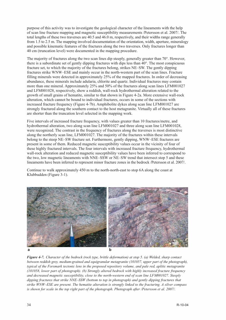
34 R-10-04
purpose of this activity was to investigate the geological character of the lineaments with the help of scan line fracture mapping and magnetic susceptibility measurements /Petersson et al. 2007/. The total lengths of these two traverses are 40.5 and 46.0 m, respectively, and their widths range generally from 1.5 to 2.5 m. The mapping involved documentation of the orientation, width, aperture, mineralogy and possible kinematic features of the fractures along the two traverses. Only fractures longer than 40 cm (truncation level) were documented in the mapping procedure.
The majority of fractures along the two scan lines dip steeply, generally greater than 70°. However, there is a subordinate set of gently dipping fractures with dips less than 40°. The most conspicuous fracture set, to which the majority of the fractures belong, strikes NE–SW. The gently dipping fractures strike WNW–ESE and mainly occur in the north-western part of the scan lines. Fracture filling minerals were detected in approximately 25% of the mapped fractures. In order of decreasing abundance, these minerals include adularia, chlorite and quartz. Individual fractures may contain more than one mineral. Approximately 25% and 50% of the fractures along scan lines LFM001027 and LFM001028, respectively, show a reddish, wall-rock hydrothermal alteration related to the growth of small grains of hematite, similar to that shown in Figure 4-2a. More extensive wall-rock alteration, which cannot be bound to individual fractures, occurs in some of the sections with increased fracture frequency (Figure 4-7b). Amphibolite dykes along scan line LFM001027 are strongly fractured along the southern contact to the host metagranite. Virtually all of these fractures are shorter than the truncation level selected in the mapping work.
Five intervals of increased fracture frequency, with values greater than 10 fractures/metre, and hydrothermal alteration, two along scan line LFM001027 and three along scan line LFM001028, were recognized. The contrast in the frequency of fractures along the traverses is most distinctive along the northerly scan line, LFM001027. The majority of the fractures within these intervals belong to the steep NE–SW fracture set. Furthermore, gently dipping, WNW–ESE fractures are present in some of them. Reduced magnetic susceptibility values occur in the vicinity of four of these highly fractured intervals. The four intervals with increased fracture frequency, hydrothermal wall-rock alteration and reduced magnetic susceptibility values have been inferred to correspond to the two, low magnetic lineaments with NNE–SSW or NE–SW trend that intersect stop 5 and these lineaments have been inferred to represent minor fracture zones in the bedrock /Petersson et al. 2007/.
Continue to walk approximately 450 m to the north-north-east to stop 6A along the coast at Klubbudden (Figure 3-1).
Figure 4-7. Character of the bedrock (rock type, brittle deformation) at stop 5. (a) Welded, sharp contact between reddish grey, medium-grained and equigranular metagranite (101057, upper part of the photograph), typical of the Forsmark tectonic lens in the proposed repository volume, and pale red, aplitic metagranite (101058, lower part of photograph). (b) Strongly altered bedrock with highly increased fracture frequency and decreased magnetic susceptibility, close to the north-western end of scan line LFM001027. Steeply dipping fractures that strike NNE–SSW (bottom to top in photograph) and gently dipping fractures that strike WNW–ESE are present. The hematite alteration is strongly linked to the fracturing. A silver compass is shown for scale in the top right part of the photograph. Photograph after /Petersson et al. 2007/.
ba
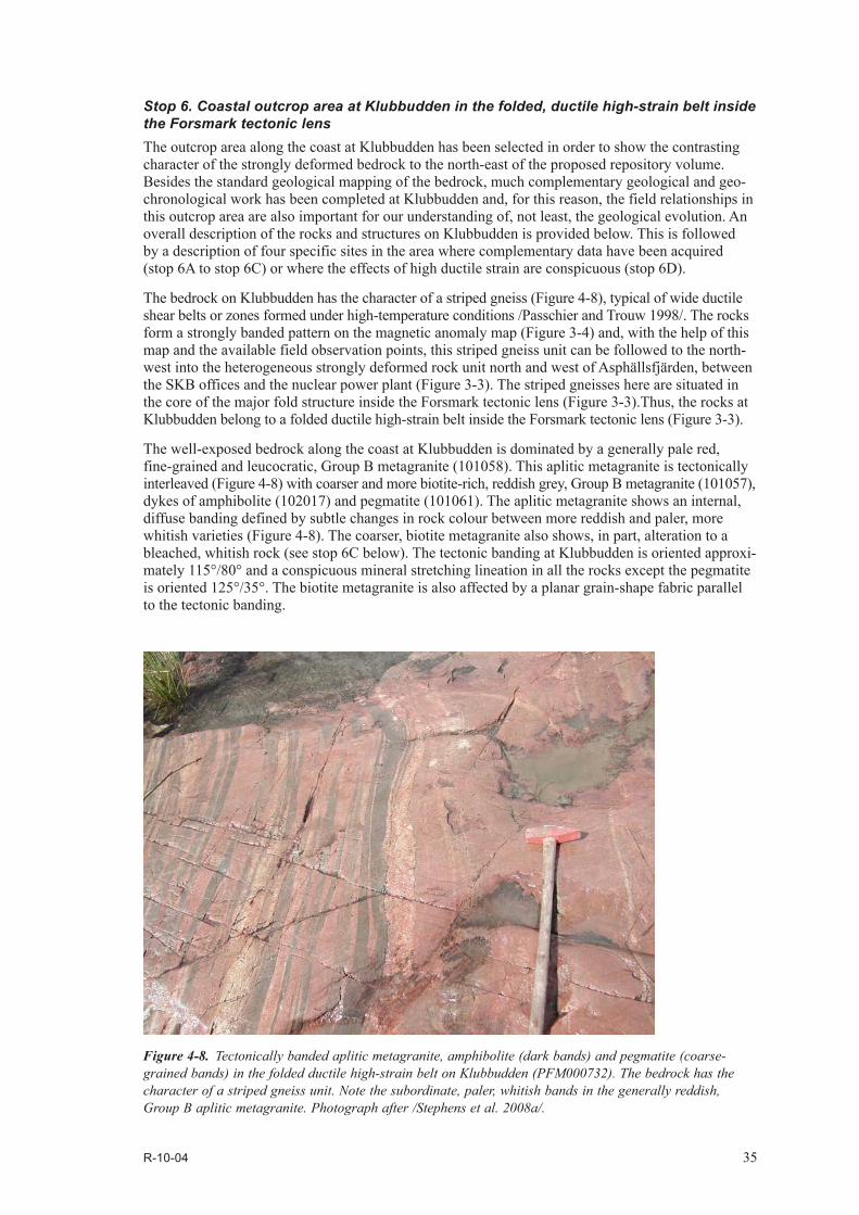
R-10-04 35
Stop 6. Coastal outcrop area at Klubbudden in the folded, ductile high-strain belt inside the Forsmark tectonic lens The outcrop area along the coast at Klubbudden has been selected in order to show the contrasting character of the strongly deformed bedrock to the north-east of the proposed repository volume. Besides the standard geological mapping of the bedrock, much complementary geological and geo-chronological work has been completed at Klubbudden and, for this reason, the field relationships in this outcrop area are also important for our understanding of, not least, the geological evolution. An overall description of the rocks and structures on Klubbudden is provided below. This is followed by a description of four specific sites in the area where complementary data have been acquired (stop 6A to stop 6C) or where the effects of high ductile strain are conspicuous (stop 6D).
The bedrock on Klubbudden has the character of a striped gneiss (Figure 4-8), typical of wide ductile shear belts or zones formed under high-temperature conditions /Passchier and Trouw 1998/. The rocks form a strongly banded pattern on the magnetic anomaly map (Figure 3-4) and, with the help of this map and the available field observation points, this striped gneiss unit can be followed to the north-west into the heterogeneous strongly deformed rock unit north and west of Asphällsfjärden, between the SKB offices and the nuclear power plant (Figure 3-3). The striped gneisses here are situated in the core of the major fold structure inside the Forsmark tectonic lens (Figure 3-3).Thus, the rocks at Klubbudden belong to a folded ductile high-strain belt inside the Forsmark tectonic lens (Figure 3-3).
The well-exposed bedrock along the coast at Klubbudden is dominated by a generally pale red, fine-grained and leucocratic, Group B metagranite (101058). This aplitic metagranite is tectonically interleaved (Figure 4-8) with coarser and more biotite-rich, reddish grey, Group B metagranite (101057), dykes of amphibolite (102017) and pegmatite (101061). The aplitic metagranite shows an internal, diffuse banding defined by subtle changes in rock colour between more reddish and paler, more whitish varieties (Figure 4-8). The coarser, biotite metagranite also shows, in part, alteration to a bleached, whitish rock (see stop 6C below). The tectonic banding at Klubbudden is oriented approxi-mately 115°/80° and a conspicuous mineral stretching lineation in all the rocks except the pegmatite is oriented 125°/35°. The biotite metagranite is also affected by a planar grain-shape fabric parallel to the tectonic banding.
Figure 4-8. Tectonically banded aplitic metagranite, amphibolite (dark bands) and pegmatite (coarse-grained bands) in the folded ductile high-strain belt on Klubbudden (PFM000732). The bedrock has the character of a striped gneiss unit. Note the subordinate, paler, whitish bands in the generally reddish, Group B aplitic metagranite. Photograph after /Stephens et al. 2008a/.
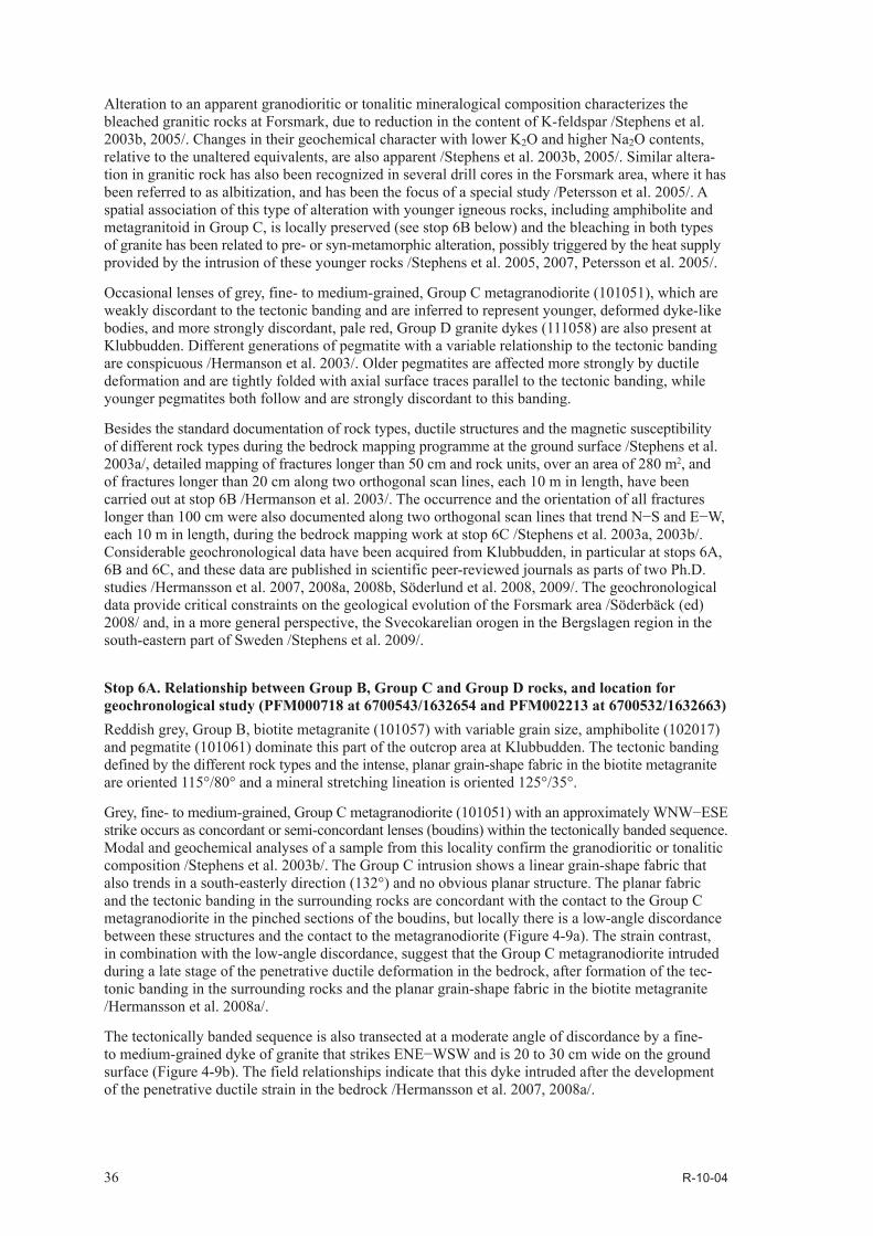
36 R-10-04
Alteration to an apparent granodioritic or tonalitic mineralogical composition characterizes the bleached granitic rocks at Forsmark, due to reduction in the content of K-feldspar /Stephens et al. 2003b, 2005/. Changes in their geochemical character with lower K2O and higher Na2O contents, relative to the unaltered equivalents, are also apparent /Stephens et al. 2003b, 2005/. Similar altera-tion in granitic rock has also been recognized in several drill cores in the Forsmark area, where it has been referred to as albitization, and has been the focus of a special study /Petersson et al. 2005/. A spatial association of this type of alteration with younger igneous rocks, including amphibolite and metagranitoid in Group C, is locally preserved (see stop 6B below) and the bleaching in both types of granite has been related to pre- or syn-metamorphic alteration, possibly triggered by the heat supply provided by the intrusion of these younger rocks /Stephens et al. 2005, 2007, Petersson et al. 2005/.
Occasional lenses of grey, fine- to medium-grained, Group C metagranodiorite (101051), which are weakly discordant to the tectonic banding and are inferred to represent younger, deformed dyke-like bodies, and more strongly discordant, pale red, Group D granite dykes (111058) are also present at Klubbudden. Different generations of pegmatite with a variable relationship to the tectonic banding are conspicuous /Hermanson et al. 2003/. Older pegmatites are affected more strongly by ductile deformation and are tightly folded with axial surface traces parallel to the tectonic banding, while younger pegmatites both follow and are strongly discordant to this banding.
Besides the standard documentation of rock types, ductile structures and the magnetic susceptibility of different rock types during the bedrock mapping programme at the ground surface /Stephens et al. 2003a/, detailed mapping of fractures longer than 50 cm and rock units, over an area of 280 m2, and of fractures longer than 20 cm along two orthogonal scan lines, each 10 m in length, have been carried out at stop 6B /Hermanson et al. 2003/. The occurrence and the orientation of all fractures longer than 100 cm were also documented along two orthogonal scan lines that trend N−S and E−W, each 10 m in length, during the bedrock mapping work at stop 6C /Stephens et al. 2003a, 2003b/. Considerable geochronological data have been acquired from Klubbudden, in particular at stops 6A, 6B and 6C, and these data are published in scientific peer-reviewed journals as parts of two Ph.D. studies /Hermansson et al. 2007, 2008a, 2008b, Söderlund et al. 2008, 2009/. The geochronological data provide critical constraints on the geological evolution of the Forsmark area /Söderbäck (ed) 2008/ and, in a more general perspective, the Svecokarelian orogen in the Bergslagen region in the south-eastern part of Sweden /Stephens et al. 2009/.
Stop 6A. Relationship between Group B, Group C and Group D rocks, and location for geochronological study (PFM000718 at 6700543/1632654 and PFM002213 at 6700532/1632663)Reddish grey, Group B, biotite metagranite (101057) with variable grain size, amphibolite (102017) and pegmatite (101061) dominate this part of the outcrop area at Klubbudden. The tectonic banding defined by the different rock types and the intense, planar grain-shape fabric in the biotite metagranite are oriented 115°/80° and a mineral stretching lineation is oriented 125°/35°.
Grey, fine- to medium-grained, Group C metagranodiorite (101051) with an approximately WNW−ESE strike occurs as concordant or semi-concordant lenses (boudins) within the tectonically banded sequence. Modal and geochemical analyses of a sample from this locality confirm the granodioritic or tonalitic composition /Stephens et al. 2003b/. The Group C intrusion shows a linear grain-shape fabric that also trends in a south-easterly direction (132°) and no obvious planar structure. The planar fabric and the tectonic banding in the surrounding rocks are concordant with the contact to the Group C metagranodiorite in the pinched sections of the boudins, but locally there is a low-angle discordance between these structures and the contact to the metagranodiorite (Figure 4-9a). The strain contrast, in combination with the low-angle discordance, suggest that the Group C metagranodiorite intruded during a late stage of the penetrative ductile deformation in the bedrock, after formation of the tec-tonic banding in the surrounding rocks and the planar grain-shape fabric in the biotite metagranite /Hermansson et al. 2008a/.
The tectonically banded sequence is also transected at a moderate angle of discordance by a fine- to medium-grained dyke of granite that strikes ENE−WSW and is 20 to 30 cm wide on the ground surface (Figure 4-9b). The field relationships indicate that this dyke intruded after the development of the penetrative ductile strain in the bedrock /Hermansson et al. 2007, 2008a/.
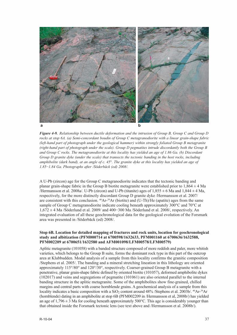
R-10-04 37
A U-Pb (zircon) age for the Group C metagranodiorite indicates that the tectonic banding and planar grain-shape fabric in the Group B biotite metagranite were established prior to 1,864 ± 4 Ma /Hermansson et al. 2008a/. U-Pb (zircon) and U-Pb (titanite) ages of 1,855 ± 6 Ma and 1,844 ± 4 Ma, respectively, for the more distinctly discordant Group D granite dyke /Hermansson et al. 2007/ are consistent with this conclusion. 40Ar-39Ar (biotite) and (U-Th)/He (apatite) ages from the same sample of Group C metagranodiorite indicate cooling beneath approximately 300°C and 70°C at 1,672 ± 4 Ma /Söderlund et al. 2009/ and 400−300 Ma /Söderlund et al. 2008/, respectively. An integrated evaluation of all these geochronological data for the geological evolution of the Forsmark area was presented in /Söderbäck (ed) 2008/.
Stop 6B. Location for detailed mapping of fractures and rock units, location for geochronological study and albitization (PFM000714 at 6700598/1632633, PFM001160 at 6700636/1632588, PFM002209 at 6700651/1632580 and AFM001098/LFM00578/LFM00579) Aplitic metagranite (101058) with a banded structure composed of more reddish and paler, more whitish varieties, which belongs to the Group B suite, forms the dominant rock type in this part of the outcrop area at Klubbudden. Modal analysis of a sample from this locality confirms the granitic composition /Stephens et al. 2005/. The banding and a mineral stretching lineation in this lithology are oriented approximately 115°/80° and 120°/30°, respectively. Coarser-grained Group B metagranite with a penetrative, planar grain-shape fabric defined by oriented biotite (101057), deformed amphibolite dykes (102017) and veins and segregations of pegmatite (101061) are also oriented parallel to the internal banding structure in the aplitic metagranite. Some of the amphibolites show fine-grained, chilled margins and central parts with coarse hornblende grains. A geochemical analysis of a sample from this locality indicates a basic composition with a SiO2 content around 48% /Stephens et al. 2003b/. 40Ar-39Ar (hornblende) dating in an amphibolite at stop 6B (PFM002209 in /Hermansson et al, 2008b/) has yielded an age of 1,796 ± 3 Ma for cooling beneath approximately 500°C. This age is considerably younger than that obtained inside the Forsmark tectonic lens (see text above and /Hermansson et al. 2008b/).
Figure 4-9. Relationship between ductile deformation and the intrusion of Group B, Group C and Group D rocks at stop 6A. (a) Semi-concordant boudin of Group C metagranodiorite with a linear grain-shape fabric (left-hand part of photograph under the geological hammer) within strongly foliated Group B metagranite (right-hand part of photograph under the scale). Group D pegmatites intrude discordantly both the Group B and Group C rocks. The metagranodiorite at this locality has yielded an age of 1.86 Ga. (b) Discordant Group D granite dyke (under the scale) that transects the tectonic banding in the host rocks, including amphibolite (dark band), at an angle of c. 45°. The granite dyke at this locality has yielded an age of 1.85−1.84 Ga. Photographs after /Söderbäck (ed) 2008/.
ba
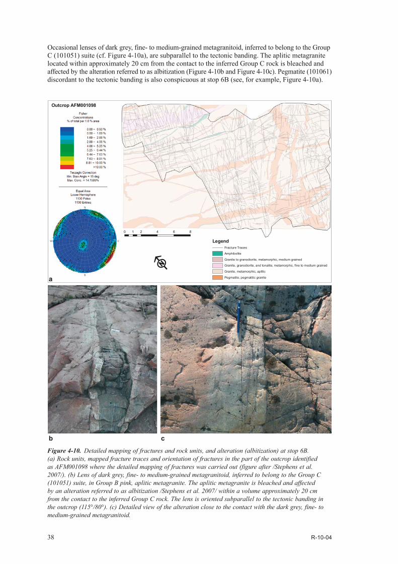
38 R-10-04
Occasional lenses of dark grey, fine- to medium-grained metagranitoid, inferred to belong to the Group C (101051) suite (cf. Figure 4-10a), are subparallel to the tectonic banding. The aplitic metagranite located within approximately 20 cm from the contact to the inferred Group C rock is bleached and affected by the alteration referred to as albitization (Figure 4-10b and Figure 4-10c). Pegmatite (101061) discordant to the tectonic banding is also conspicuous at stop 6B (see, for example, Figure 4-10a).
Figure 4-10. Detailed mapping of fractures and rock units, and alteration (albitization) at stop 6B. (a) Rock units, mapped fracture traces and orientation of fractures in the part of the outcrop identified as AFM001098 where the detailed mapping of fractures was carried out (figure after /Stephens et al. 2007/). (b) Lens of dark grey, fine- to medium-grained metagranitoid, inferred to belong to the Group C (101051) suite, in Group B pink, aplitic metagranite. The aplitic metagranite is bleached and affected by an alteration referred to as albitization /Stephens et al. 2007/ within a volume approximately 20 cm from the contact to the inferred Group C rock. The lens is oriented subparallel to the tectonic banding in the outcrop (115°/80°). (c) Detailed view of the alteration close to the contact with the dark grey, fine- to medium-grained metagranitoid.
0 2 4 6 81
F
LegendFracture Traces
Amphibolite
Granite to granodiorite, metamorphic, medium grained
Granite, granodiorite, and tonalite, metamorphic, fine to medium grained
Granite, metamorphic, aplitic
Pegmatite, pegmatitic granite
Outcrop AFM001098
cb
a

R-10-04 39
Detailed mapping of rock units and fractures longer than 0.5 m was carried out over an area of 280 m2 (AFM001098) at stop 6B /Hermanson et al. 2003/, following the standard geological mapping at the ground surface (PFM000714 in /Stephens et al. 2003a/). These data were subsequently evaluated in the context of the statistical modelling of fractures and minor deformation zones at the Forsmark site /Fox et al. 2007, SKB 2008/. Detailed mapping of fractures longer than 0.2 m was also carried out inside this limited area along two orthogonal scan lines (LFM000578 and LFM000579), each 10 m in length /Hermanson et al. 2003/. Abundant, steeply dipping fractures that strike NNE−SSW and NE−SW or WNW−ENE and NW−SE as well as a subordinate set of fractures that are gently dipping are present in the area that was mapped in detail (Figure 4-10a). The mapped outcrop area contains over 1,100 fractures longer than 0.5 m /Stephens et al. 2007/ with an average fracture frequency of approximately 4/m2. This value is considerably larger than the values obtained at the four locations inside the Forsmark tectonic lens (1.5−2/m2), where detailed fracture mapping has been carried out in the bedrock between inferred fracture zones.
Stop 6C. Relationship between deformation and Group D rocks, location for geochronological study, location for mapping of fractures and albitization (PFM000713 at 6700615/1632520, PFM002210 at 6700655/1632484, PFM002212 at 6700648/1632494 and LFM000351/LFM000352)Group B aplitic metagranite (101058), coarser-grained Group B metagranite with a penetrative, planar grain-shape fabric defined by oriented biotite (101057) and amphibolite (102017), with concordant or discordant veins of pegmatite (101061), dominate in this part of the outcrop area. The coarser-grained metagranite locally shows the bleaching alteration referred to as albitization (Figure 4-11a). Modal and geochemical analyses of an altered sample from this locality indicate a low content of K-feldspar (9%), a low content of K2O (0.74%) and a high content of Na2O (4.93%) relative to unaltered Group B metagranite in the Forsmark area /Stephens et al. 2003b/. The tectonic banding between different rock types and the planar grain-shape fabric are oriented 120°/80° and a mineral stretching lineation is oriented 130°/30−40°.
The planar grain-shape fabric in the coarser-grained, Group B biotite metagranite is transected at a high angle of discordance (Figure 4-11b) by a dyke composed of red, fine-grained, Group D granite (111058), i.e. similar field relationships between the rocks in Groups B and D are observed at stop 6C as those observed at stop 6A (cf. Figure 4-9b). Modal and geochemical analyses of a Group D sample from this locality confirm the granitic composition /Stephens et al. 2003b/. A U-Pb (zircon) age of 1,851 ± 5 Ma for the granite dyke (PFM002210 in /Hermansson et al. 2007/) indicates that the penetrative ductile strain in the surrounding biotite metagranite occurred prior to approximately 1,850 million years ago /Hermansson et al. 2007/.
An integration of the critical field relationships and the U-Pb (zircon) geochronological data at three localities inside and to the north-east of the Forsmark tectonic lens (Nordskäret close to drill site 6, stop 6A and stop 6C) suggests that penetrative ductile deformation under amphibolite-facies metamorphic conditions commenced and reached a waning stage in its evolution within the narrow time interval between 1,871 and 1,860 Ma /Hermansson et al. 2008a/. Uncertainties in the U-Pb (zircon) age are taken into account in this estimation. Titanite ages from amphibolite suggest that dolerites intruded the Group B rocks, and were converted to amphibolite, before 1,857 Ma, which adds support to this statement /Hermansson et al. 2008a/. Penetrative ductile deformation under amphibolite-facies meta morphic conditions was completed prior to the intrusion of the cross-cutting Group D dykes between 1,861 and 1,846 Ma /Hermansson et al. 2007/. After approximately 1,850 million years ago, ductile deformation at Forsmark was restricted to the retrograde deformation zones that embrace the tectonic lens.
The occurrence and orientation of fractures longer than 1 m were documented at stop 6C along two orthogonal scan lines that trend N−S and E−W, each 10 m in length, during the bedrock geological mapping work (LFM000351 and LFM000352 in /Stephens et al. 2003a/). Steeply dipping fractures that strike NNE−SSW to ENE−WSW, strongly discordant to the ductile fabric in the rocks at this stop, and steeply dipping fractures that strike WNW−ESE, more or less parallel to the ductile fabric, are conspicuous components (cf. also Figure 4-10a). The frequency of fractures along each scan line is 2.6 and 2.5 fractures per metre, respectively /Stephens et al. 2003b/. These values are distinctly higher than the values obtained from similar data inside the Forsmark tectonic lens (cf. for example, stops 3 and 4).

40 R-10-04
Stop 6D. Mylonitized, biotite metagranite (PFM000709 at 6700658/1632430) Reddish grey, Group B, biotite metagranite (101057), amphibolite (102017) and pegmatite (101061) dominate this part of the outcrop area at Klubbudden. Deformed pegmatite dykes, which are concor-dant with the planar grain-shape fabric defined by oriented grains of biotite in the metagranite, show a wave-like pattern of parallel V-shaped grooves and rounded ridges referred to as mullion structure (Figure 4-12a). These structures testify to a significant contrast in ductility between the pegmatite and the surrounding biotite metagranite. Biotite is also conspicuous along the contact between these two rocks (Figure 4-12a).
Locally, the biotite metagranite can be traced without any abrupt contact into a grey, fine-grained mylonite that formed as a result of intense ductile strain under amphibolite facies metamorphic con-ditions (Figure 4-12b). Dark grey bands in the mylonite are conspicuous (Figure 4-12b). This rock differs markedly from the fine-grained and leucocratic rock with more reddish and paler, more whitish bands that is an important rock component at Klubbudden (banded aplitic metagranite labelled as rock code 101058 at stops 6B and 6C). Both the planar grain-shape fabric in the metagranite, defined by oriented biotite grains, and the mylonitic banding strike 120°/90°. A mineral stretching lineation at this locality is oriented 125°/30°.
Drive to stop 7 along the coast close to the SKB offices (Figure 3-1).
Stop 7. Roadside and coastal outcrop north-west of the SKB offices in the ductile high-strain belt north-east of the Forsmark tectonic lens (PFM001156 at 6701371/1632016 to PFM001235 at 6701402/1632065)The outcrop at stop 7 has been chosen to illustrate the character of the bedrock in the ductile high-strain belt to the north-east of the Forsmark tectonic lens (Figure 3-3) and outside the proposed repository volume. Besides the standard documentation of rock types, ductile structures and the magnetic suscept-ibility of different rock types during the bedrock mapping programme at the ground surface /Stephens et al. 2003a/, the modal and geochemical compositions of a sample of a felsic rock type from this locality have been determined. Furthermore, field kinematic data are also available at stop 7 that constrain the sense of movement in connection with the high-temperature ductile deformation in the Forsmark area.
Figure 4-11. Character of the bedrock (alteration, deformation-intrusion relationships) at stop 6C. (a) Medium-grained, Group B, biotite metagranite affected in the upper part of the photograph by the bleaching alteration referred to as albitization. (b) Planar grain-shape fabric in medium-grained, Group B, biotite metagranite in the right-hand part of the photograph transected at a high angle of discordance by a dyke composed of red, fine-grained, Group D granite (111058) in the left-hand part of the photograph. Note also the fractures close to and along the contact between these two rocks. The field relationship between ductile deformation and Group D rock resembles that observed at stop 6A (see Figure 4-9b).
ba

R-10-04 41
An heterogeneous, tectonically banded sequence is exposed in the southern part of stop 7 close to the road between the SKB offices and the nuclear power plant, around the coordinates 6701371/1632016 (PFM001156). The tectonic banding is oriented 130°/90°. Grey, fine-grained and finely banded, felsic rock, which is possibly volcanic in origin and included in the Group A suite of rocks (103076), forms the dominant rock component in this part of the outcrop (Figure 4-13a). Modal and geochemical analyses indicate a dacitic composition. Subordinate components in the banded sequence (Figure 4-13b) comprise:
• Dark grey, fine- to medium-grained, veined, in part porphyritic metadiorite (101033) that occur as dykes in the dominant, inferred felsic metavolcanic rock.
• Fine-grained amphibolite (102017) that also occurs as dykes in the dominant, inferred felsic metavolcanic rock.
• Pegmatite (101061) that occurs as both semi-concordant boudins and discordant, dyke-like bodies.
• Fine-grained, pale red to grey granite, in part spatially associated with pegmatite (111058 in Group D?).
• Highly subordinate amphibole-garnet skarn (108019) as concordant lenses. This lithology is typically associated with 1.91−1.89 Ga felsic metavolcanic rocks in south-central Sweden.
• Pale grey to white metagranite (101057) that has only been observed as a subordinate rock component in the part of the outcrop that is exposed along the road.
Minor folds with both S- and Z-asymmetry (Figure 4-13a and Figure 4-13b, respectively) and an eye-shaped structure (Figure 4-13c), inferred to be a sheath fold, are present in the outcrop. These folds deform the tectonic banding including the dykes (Figure 4-13a and Figure 4-13b). There is some indication of a component of dextral strike-slip movement in a rotated pegmatite remnant along the ductile planar fabric in the part of the outcrop close to the eye-shaped structure (Figure 4-13d). A minor fold in amphibolite exposed along the road rotates a planar grain-shape fabric in the amphibolite. A mineral lineation, defined by oriented hornblende grains, is oriented 130°/45°, more or less parallel to the fold axis that is oriented 130°/50°. A steeply dipping fracture zone, which is 10−30 cm wide, strikes in a ENE-WSW direction (235°/70°) across the southern part of the outcrop at stop 7. Subvertical fractures oriented along the ductile planar fabric in the bedrock are also conspicuous.
Walk approximately 25 m to the north-east, more or less along the coastline, to the part of stop 7 around the coordinates 6701393/1632042 (PFM001234).
Figure 4-12. Character of the bedrock (mullion structure, development of mylonite) at stop 6D. (a) Mullion structure along contact between pegmatite dyke and reddish grey, Group B, biotite metagranite. Note also the high concentration of the dark mineral biotite along the contact between these two rocks. (b) Mylonitized biotite metagranite on both sides of the pen in the photograph. Coarser, less deformed metagranite occurs in the left-hand part of the photograph. The mylonitic banding is oriented 120°/90° and a mineral stretching lineation at this locality is oriented 125°/30°.
ba
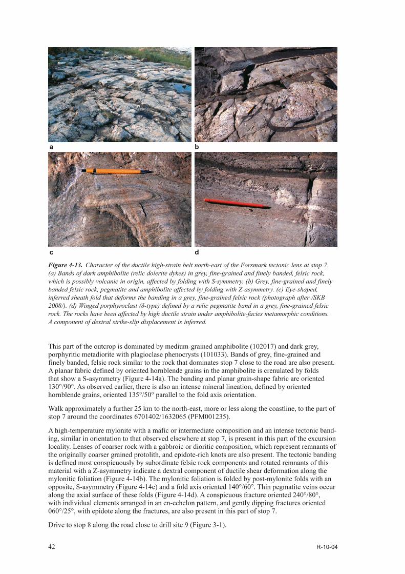
42 R-10-04
This part of the outcrop is dominated by medium-grained amphibolite (102017) and dark grey, porphyritic metadiorite with plagioclase phenocrysts (101033). Bands of grey, fine-grained and finely banded, felsic rock similar to the rock that dominates stop 7 close to the road are also present. A planar fabric defined by oriented hornblende grains in the amphibolite is crenulated by folds that show a S-asymmetry (Figure 4-14a). The banding and planar grain-shape fabric are oriented 130°/90°. As observed earlier, there is also an intense mineral lineation, defined by oriented hornblende grains, oriented 135°/50° parallel to the fold axis orientation.
Walk approximately a further 25 km to the north-east, more or less along the coastline, to the part of stop 7 around the coordinates 6701402/1632065 (PFM001235).
A high-temperature mylonite with a mafic or intermediate composition and an intense tectonic band-ing, similar in orientation to that observed elsewhere at stop 7, is present in this part of the excursion locality. Lenses of coarser rock with a gabbroic or dioritic composition, which represent remnants of the originally coarser grained protolith, and epidote-rich knots are also present. The tectonic banding is defined most conspicuously by subordinate felsic rock components and rotated remnants of this material with a Z-asymmetry indicate a dextral component of ductile shear deformation along the mylonitic foliation (Figure 4-14b). The mylonitic foliation is folded by post-mylonite folds with an opposite, S-asymmetry (Figure 4-14c) and a fold axis oriented 140°/60°. Thin pegmatite veins occur along the axial surface of these folds (Figure 4-14d). A conspicuous fracture oriented 240°/80°, with individual elements arranged in an en-echelon pattern, and gently dipping fractures oriented 060°/25°, with epidote along the fractures, are also present in this part of stop 7.
Drive to stop 8 along the road close to drill site 9 (Figure 3-1).
Figure 4-13. Character of the ductile high-strain belt north-east of the Forsmark tectonic lens at stop 7. (a) Bands of dark amphibolite (relic dolerite dykes) in grey, fine-grained and finely banded, felsic rock, which is possibly volcanic in origin, affected by folding with S-symmetry. (b) Grey, fine-grained and finely banded felsic rock, pegmatite and amphibolite affected by folding with Z-asymmetry. (c) Eye-shaped, inferred sheath fold that deforms the banding in a grey, fine-grained felsic rock (photograph after /SKB 2008/). (d) Winged porphyroclast (δ-type) defined by a relic pegmatite band in a grey, fine-grained felsic rock. The rocks have been affected by high ductile strain under amphibolite-facies metamorphic conditions. A component of dextral strike-slip displacement is inferred.
ba
dc
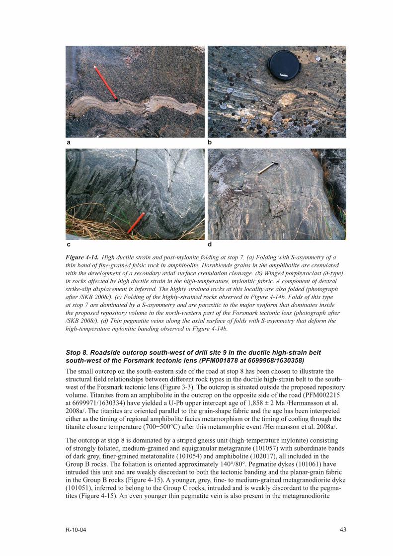
R-10-04 43
Stop 8. Roadside outcrop south-west of drill site 9 in the ductile high-strain belt south-west of the Forsmark tectonic lens (PFM001878 at 6699968/1630358)The small outcrop on the south-eastern side of the road at stop 8 has been chosen to illustrate the structural field relationships between different rock types in the ductile high-strain belt to the south-west of the Forsmark tectonic lens (Figure 3-3). The outcrop is situated outside the proposed repository volume. Titanites from an amphibolite in the outcrop on the opposite side of the road (PFM002215 at 6699971/1630334) have yielded a U-Pb upper intercept age of 1,858 ± 2 Ma /Hermansson et al. 2008a/. The titanites are oriented parallel to the grain-shape fabric and the age has been interpreted either as the timing of regional amphibolite facies metamorphism or the timing of cooling through the titanite closure temperature (700−500°C) after this metamorphic event /Hermansson et al. 2008a/.
The outcrop at stop 8 is dominated by a striped gneiss unit (high-temperature mylonite) consisting of strongly foliated, medium-grained and equigranular metagranite (101057) with subordinate bands of dark grey, finer-grained metatonalite (101054) and amphibolite (102017), all included in the Group B rocks. The foliation is oriented approximately 140°/80°. Pegmatite dykes (101061) have intruded this unit and are weakly discordant to both the tectonic banding and the planar-grain fabric in the Group B rocks (Figure 4-15). A younger, grey, fine- to medium-grained metagranodiorite dyke (101051), inferred to belong to the Group C rocks, intruded and is weakly discordant to the pegma-tites (Figure 4-15). An even younger thin pegmatite vein is also present in the metagranodiorite
Figure 4-14. High ductile strain and post-mylonite folding at stop 7. (a) Folding with S-asymmetry of a thin band of fine-grained felsic rock in amphibolite. Hornblende grains in the amphibolite are crenulated with the development of a secondary axial surface crenulation cleavage. (b) Winged porphyroclast (δ-type) in rocks affected by high ductile strain in the high-temperature, mylonitic fabric. A component of dextral strike-slip displacement is inferred. The highly strained rocks at this locality are also folded (photograph after /SKB 2008/). (c) Folding of the highly-strained rocks observed in Figure 4-14b. Folds of this type at stop 7 are dominated by a S-asymmetry and are parasitic to the major synform that dominates inside the proposed repository volume in the north-western part of the Forsmark tectonic lens (photograph after /SKB 2008/). (d) Thin pegmatite veins along the axial surface of folds with S-asymmetry that deform the high-temperature mylonitic banding observed in Figure 4-14b.
ba
dc
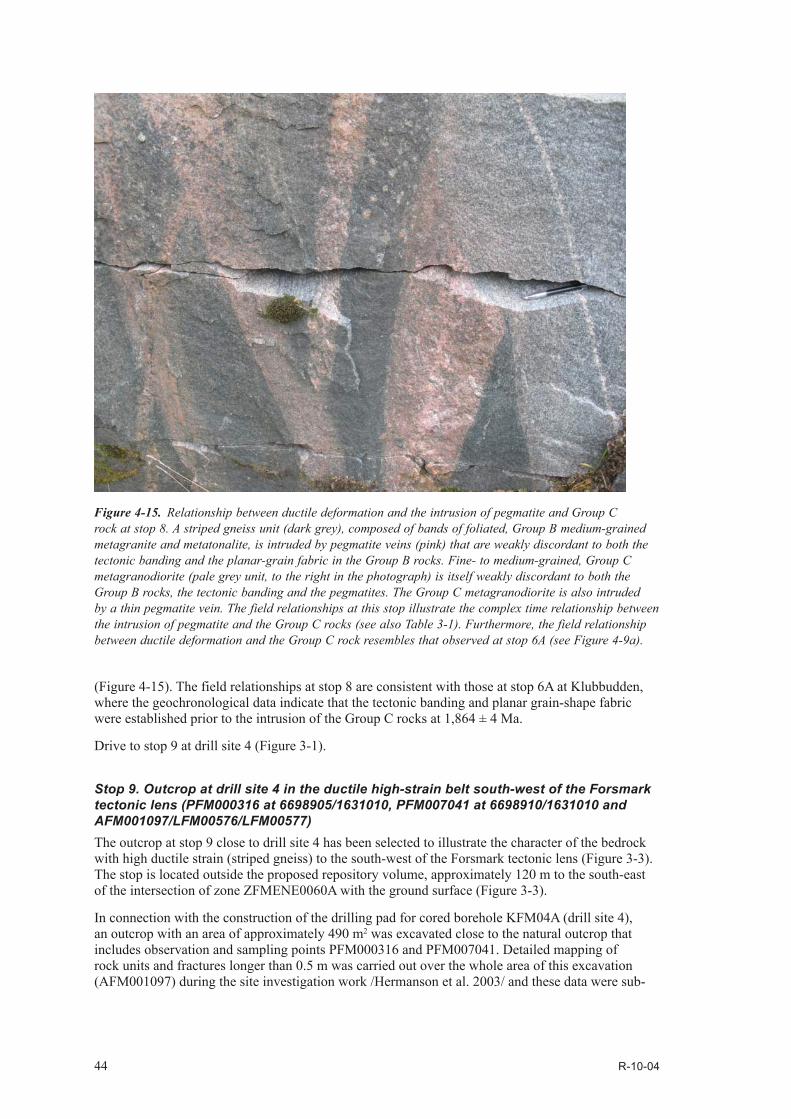
44 R-10-04
(Figure 4-15). The field relationships at stop 8 are consistent with those at stop 6A at Klubbudden, where the geochronological data indicate that the tectonic banding and planar grain-shape fabric were established prior to the intrusion of the Group C rocks at 1,864 ± 4 Ma.
Drive to stop 9 at drill site 4 (Figure 3-1).
Stop 9. Outcrop at drill site 4 in the ductile high-strain belt south-west of the Forsmark tectonic lens (PFM000316 at 6698905/1631010, PFM007041 at 6698910/1631010 and AFM001097/LFM00576/LFM00577)The outcrop at stop 9 close to drill site 4 has been selected to illustrate the character of the bedrock with high ductile strain (striped gneiss) to the south-west of the Forsmark tectonic lens (Figure 3-3). The stop is located outside the proposed repository volume, approximately 120 m to the south-east of the intersection of zone ZFMENE0060A with the ground surface (Figure 3-3).
In connection with the construction of the drilling pad for cored borehole KFM04A (drill site 4), an outcrop with an area of approximately 490 m2 was excavated close to the natural outcrop that includes observation and sampling points PFM000316 and PFM007041. Detailed mapping of rock units and fractures longer than 0.5 m was carried out over the whole area of this excavation (AFM001097) during the site investigation work /Hermanson et al. 2003/ and these data were sub-
Figure 4-15. Relationship between ductile deformation and the intrusion of pegmatite and Group C rock at stop 8. A striped gneiss unit (dark grey), composed of bands of foliated, Group B medium-grained metagranite and metatonalite, is intruded by pegmatite veins (pink) that are weakly discordant to both the tectonic banding and the planar-grain fabric in the Group B rocks. Fine- to medium-grained, Group C metagranodiorite (pale grey unit, to the right in the photograph) is itself weakly discordant to both the Group B rocks, the tectonic banding and the pegmatites. The Group C metagranodiorite is also intruded by a thin pegmatite vein. The field relationships at this stop illustrate the complex time relationship between the intrusion of pegmatite and the Group C rocks (see also Table 3-1). Furthermore, the field relationship between ductile deformation and the Group C rock resembles that observed at stop 6A (see Figure 4-9a).

R-10-04 45
sequently evaluated in the context of the statistical modelling of fractures and minor deformation zones at the Forsmark site /Fox et al. 2007, SKB 2008/. Furthermore, detailed mapping of fractures longer than 0.2 m was carried out inside the excavated area along two orthogonal scan lines (LFM00576 and LFM00577), each 10 m in length /Hermanson et al. 2003/. The excavation was later covered by unconsolidated surface material and used as a parking place for drill site 4. An 40Ar-39Ar (biotite) age from a metatonalite in the outcrop at stop 9 (PFM007041) indicates cooling beneath approximately 300°C at 1,666 ± 5 Ma /Söderlund et al. 2009/.
A tightly banded sequence (Figure 4-16a) dominated by medium-grained, grey metatonalite (101054) and fine-grained, pale grey felsic rock (103076) with occasional epidote skarn bands (108019 and Figure 4-16b), inferred to be volcanic in origin, is prominent at stop 9. Metatonalite dominates in the southern part of the outcrop and the inferred felsic metavolcanic rock with skarn is conspicuous closer to the gravel road in the northern part of the outcrop. Concordant amphibolite bands (102017), pegmatite boudins (101061) and weakly discordant, dyke-like bodies of pale red granite (111058) form subordinate components at the outcrop. The tectonic banding is oriented approximately 120°/85° and a mineral stretching lineation in the metatonalite plunges 130°/30°.
Figure 4-16. Character of the ductile high-strain belt south-west of the Forsmark tectonic lens and dis-cordant brittle structures at stop 9. (a) Tectonically banded sequence of foliated and lineated metatonalite, felsic metavolcanic rock and amphibolite in a striped gneiss unit along the ductile high-strain belt to the south-west of the Forsmark tectonic lens. The thin granitic vein to the right in the photograph is weakly discordant to the tectonic banding (photograph after /Stephens et al. 2008a/). (b) Bands of epidote skarn in felsic metavolcanic rock with probable bedding structure, within the striped gneiss unit. (c) Steep fractures with a north-easterly strike direction are associated with intense wall-rock alteration and are discordant to the main ductile planar grain-shape fabric and tectonic banding in predominantly fine-grained felsic metavolcanic rock. (d) Minor fault that strikes approximately E−W is discordant to the tectonic banding defined by fine-grained felsic metavolcanic rock and coarser-grained metatonalite. The fault is located along the limb of a minor fold that deforms the tectonic banding and ductile planar grain-shape fabric.
dc
a b

46 R-10-04
Steeply dipping fractures that strike 030° and 060° and show a reddish wall-rock hydrothermal alteration, related to the growth of small grains of hematite, are strongly discordant to the ductile fabric in the bedrock (Figure 4-16c). There is also clear evidence for displacement along fractures that strike approximately E−W (Figure 4-16d) and then bend into and more or less follow the ductile fabric.
Drive to stop 10 directly north-west of the lake Eckarfjärden and close to the site where borehole HFM11 was drilled (Figure 3-1). Park in a small parking place by HFM11.
Stop 10. Outcrop along the Eckarfjärden deformation zone south-west of the Forsmark tectonic lens (PFM002218 at 6697402/1631521, PFM007086 at 6697398/1631527 and PFM007090 at 6697396/1631520) The character and sense of displacement of the ductile-brittle and brittle strain along the regionally significant Eckarfjärden deformation zone have been investigated at ten field locations. The results of the field and subsequent microstructural studies have been described in /Nordgulen and Saintot 2006/ and paleostress fields have been constructed at seven of these locations /Saintot et al. submit-ted for publication 2010/. Two of these locations (PFM007086 and PFM007090) occur in an outcrop approximately 200 m north-west of the drill site for percussion borehole HFM11, which is situated close to the gravel road west of the lake Eckarfjärden. These two field locations comprise together stop 10 (Figure 3-2), the description of which below is based mainly on that in /Nordgulen and Saintot 2006/. This outcrop was also described briefly in the standard bedrock mapping programme at the ground surface (PFM002218). The outcrop is composed of metagranite strongly affected by low-grade mylonitization and later brittle deformation along the Eckarfjärden deformation zone.
Epidote-rich bands of low-grade mylonite and ultramylonite in hydrothermally altered, protomy-lonitic metagranite are conspicuous at stop 10 (PFM007090) and are oriented parallel to the planar grain-shape fabric (150°/90° to 330°/80°) in the metagranite (Figure 4-17a). Microstructural work has shown that the ductile fabric, including the mylonitic banding, is partly disrupted and broken up by later cataclasis (/Nordgulen and Saintot 2006/ and Figure 4-17b and c).
Steeply dipping, epidote- and quartz-rich shear fractures with NNW−SSE to NW−SE and NE−SW strike (PFM007090), some of which show shear striae with a gentle to moderate plunge indicative of a conspicuous strike-slip component of displacement, and a fault that dips gently to the south-south-east and contains epidote ± chlorite, dip-slip shear striae (PFM007086) comprise an older set of brittle structures /Nordgulen and Saintot 2006/. In this context, it is worthwhile noting that epidote, chlorite and quartz belong to the oldest generation of fracture minerals recognized at Forsmark /Sandström et al. 2008, 2009/. The sense of brittle shear deformation could not be determined from any of the fault-slip data /Nordgulen and Saintot 2006/. However, a strike-slip brittle regime with an approximately N−S horizontal σ1 axis has been reconstructured on the basis that the steeply dipping fractures form a conjugate set /Saintot et al. submitted for publication 2010/. This regime is inferred to have developed at a late stage during the Svecokarelian orogeny /Saintot et al. submitted for publication/.
Based on the documentation of cross-cutting relationships at PFM007086, it is apparent that a steeply dipping, laumontite-filled fracture with ENE−WSW strike and steeply dipping fractures with an approximately N−S strike, filled by a pale green mineral, formed after steeply dipping epidote-filled fractures with NNE−SSW to NE−SW strike and the gently dipping fault that dips to the south-south-east, respectively /Nordgulen and Saintot 2006/. Dextral and sinistral components of displacement along steeply dipping fractures filled by the pale green mineral with NNE−SSW and E−W strike, respectively, indicate the influence of a younger paleostress field with an approximately NE−SW σ1 axis /Nordgulen and Saintot 2006, Saintot et al. submitted for publication 2010/. Sinistral displacement was also observed along the steeply dipping fracture with ENE−WSW strike filled by laumontite.
The observations at stop 10 form the basis to two important conclusions:
• Brittle reactivation of the ductile fabric occurred along the Eckarfjärden deformation zone.
• A complex, polyphase brittle deformation history occurred along the Eckarfjärden deformation zone under the influence of different paleostress fields.
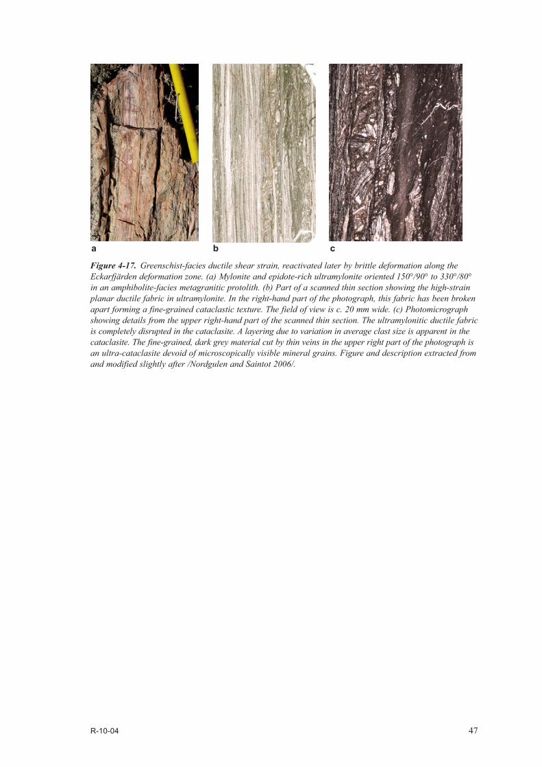
R-10-04 47
Figure 4-17. Greenschist-facies ductile shear strain, reactivated later by brittle deformation along the Eckarfjärden deformation zone. (a) Mylonite and epidote-rich ultramylonite oriented 150°/90° to 330°/80°
in an amphibolite-facies metagranitic protolith. (b) Part of a scanned thin section showing the high-strain planar ductile fabric in ultramylonite. In the right-hand part of the photograph, this fabric has been broken apart forming a fine-grained cataclastic texture. The field of view is c. 20 mm wide. (c) Photomicrograph showing details from the upper right-hand part of the scanned thin section. The ultramylonitic ductile fabric is completely disrupted in the cataclasite. A layering due to variation in average clast size is apparent in the cataclasite. The fine-grained, dark grey material cut by thin veins in the upper right part of the photograph is an ultra-cataclasite devoid of microscopically visible mineral grains. Figure and description extracted from and modified slightly after /Nordgulen and Saintot 2006/.
a b c
R-10-04 49
5 References
SKB’s (Svensk Kärnbränslehantering AB) publications can be found at www.skb.se/publications.
Bergman T, Andersson J, Hermansson T, Zetterström Evins L, Petersson J, Albrecht L, Nordman C, Stephens M B, 2004. Bedrock mapping. Stage 2 (2003) − Bedrock data from outcrops and the basal parts of trenches and shallow boreholes through the Quaternary cover. Forsmark site investigation. SKB P-04-91, Svensk Kärnbränslehantering AB.
Blyth F G H, de Freitas M H, 1984. A Geology for Engineers, 7th edition. Edward Arnold, London, 325 pp.
Carlsson A, 1979. Characteristic features of a superficial rock mass in southern central Sweden – Horizontal and subhorizontal fractures and filling material. Striae 11, 1−79.
Cederbom C, 2001. Phanerozoic, pre-Cretaceous thermotectonic events in southern Sweden revealed by fission track thermochronology. Earth and Planetary Science Letters 188, 199−209.
Follin S, 2008. Bedrock hydrogeology Forsmark. Site descriptive modelling, SDM-Site Forsmark. SKB R-08-95, Svensk Kärnbränslehantering AB.
Follin S, Stephens M B, Laaksoharju M, Nilsson A-C, Smellie J A T, Tullborg E-L, 2008. Modelling the evolution of hydrochemical conditions in the Fennoscandian Shield during Holocene time using multidisciplinary information. Applied Geochemistry 23, 2004−2020.
Fox A, La Pointe P, Hermanson J, Öhman J, 2007. Statistical geological discrete fracture network model, Forsmark modelling stage 2.2. SKB R-07-46, Svensk Kärnbränslehantering AB.
Glamheden R, Fredriksson A, Persson L, Röshoff K, Karlsson J, Bohlin H, Lindberg U, Hakami H, Hakami E, Johansson M, 2007. Rock mechanics Forsmark, Site descriptive modelling Forsmark stage 2.2. SKB R-07-31, Svensk Kärnbränslehantering AB.
Hedenström A, Sohlenius G, 2008. Description of the regolith at Forsmark. Site descriptive modelling, SDM-Site Forsmark. SKB R-08-04, Svensk Kärnbränslehantering AB.
Hermanson J, Hansen L, Vestgård J, Leiner P, 2003. Detailed fracture mapping of the outcrops Klubbudden, AFM001098 and drill site 4, AFM001097. Forsmark site investigation. SKB P-03-115, Svensk Kärnbränslehantering AB.
Hermanson J, Hansen L, Vestgård J, Leiner P, 2004. Detailed fracture mapping of excavated rock outcrop at drilling site 5, AFM100201. Forsmark site investigation. SKB P-04-90, Svensk Kärnbränslehantering AB.
Hermansson T, Stephens M B, Corfu F, Andersson J, Page L, 2007. Penetrative ductile deformation and amphibolite-facies metamorphism prior to 1851 Ma in the western part of the Svecofennian orogen, Fennoscandian Shield. Precambrian Research 153, 29−45.
Hermansson T, Stephens M B, Corfu F, Page L M, Andersson J, 2008a. Migratory tectonic switching, western Svecofennian orogen, central Sweden: Constraints from U/Pb zircon and titanite geochronology. Precambrian Research 161, 250−278.
Hermansson T, Stephens M B, Page L M, 2008b. 40Ar/39Ar hornblende geochronology from the Forsmark area in central Sweden – constraints on late Svecofennian cooling, ductile deformation and exhumation. Precambrian Research 167, 303−315.
Hietanen A, 1975. Generation of potassium-poor magmas in the northern Sierra Nevada and the Svecofennian in Finland. Journal of Research U.S. Geological Survey 3, 631−645.
Isaksson H, Thunehed H, Pitkänen T, Keisu M, 2006. Detailed ground and marine magnetic survey and lineament interpretation in the Forsmark area – 2006. Forsmark site investigation. SKB P-06-261, Svensk Kärnbränslehantering AB.
Juhlin C, Stephens M B, 2006. Gently dipping fracture zones in Paleoproterozoic metagranite, Sweden: Evidence from reflection seismic and cored borehole data and implications for the disposal of nuclear waste. Journal of Geophysical Research 111, B09302, 19 pp.

50 R-10-04
Koistinen T, Stephens M B, Bogatchev V, Nordgulen O, Wennerström M, Korhonen J, 2001. Geological map of the Fennoscandian Shield, scale 1:2 000 000. Geological Surveys of Finland, Norway and Sweden and the North-West Department of Natural Resources of Russia.
Larson S Å, Tullborg E-L, Cederbom C, Stiberg J-P, 1999. Sveconorwegian and Caledonian foreland basins in the Baltic Shield revealed by fission-track thermochronology. Terra Nova 11, 210−215.
Leijon B (ed), 2005. Forsmark site investigation. Investigations of superficial fracturing and block displacements at drill site 5. SKB P-05-199, Svensk Kärnbränslehantering AB.
Lidmar-Bergström K, 1994. Morphology of the bedrock surface. In C Fredén (edit.), Geology. National Atlas of Sweden, 1st edition, 44−54.
Lundqvist J, 1994. The deglaciation. In C Fredén (edit.), Geology. National Atlas of Sweden, 1st edition, 124−135.
Martin C D, 2007. Quantifying in situ stress magnitudes and orientations for Forsmark. Forsmark stage 2.2. SKB R-07-26, Svensk Kärnbränslehantering AB.
Nordgulen Ø, Saintot A, 2006. The character and kinematics of deformation zones (ductile shear zones, fault zones and fracture zones) at Forsmark – report from phase 1. Forsmark site investiga-tion. SKB P-06-212, Svensk Kärnbränslehantering AB.
Olofsson I, Simeonov A, Stigsson M, Stephens M, Follin S, Nilsson A-C, Röshoff K, Lindberg U, Lanaro F, Fredriksson A, Persson L, 2007. Site descriptive modelling Forsmark, stage 2.2. A fracture domain concept as a basis for the statistical modelling of fractures and minor deformation zones, and interdisciplinary coordination. SKB R-07-15, Svensk Kärnbränslehantering AB.
Page L, Hermansson T, Söderlund P, Andersson J, Stephens M B, 2004. Forsmark site investigation. Bedrock mapping. U/Pb, 40Ar/39Ar and (U-Th)/He geochronology. SKB P-04-126, Svensk Kärnbränslehantering AB.
Page L, Hermansson T, Söderlund P, Stephens M B, 2007. Forsmark site investigation. 40Ar/39Ar and U-Th/He geochronology: Phase 2. SKB P-06-211, Svensk Kärnbränslehantering AB.
Passchier C W, Trouw R A J, 1998. Microtectonics. Springer-Verlag, Berlin, 289 pp.
Paulamäki S, 2009. Geological setting of the Olkiluoto investigation site, Eurajoki, SW Finland. Excursion guidebook. Working report 2009-53, Posiva Oy, Eurajoki.
Petersson J, Berglund J, Danielsson P, Skogsmo G, 2005. Petrographic and geochemical characteristics of bedrock samples from boreholes KFM04A-06A, and a whitened alteration rock. Forsmark site investigation. SKB P-05-156, Svensk Kärnbränslehantering AB.
Petersson J, Andersson U B, Berglund J, 2007. Scan line fracture mapping and magnetic susceptibility measurements across two low magnetic lineaments with NNE and NE trend, Forsmark. In Stephens M B and Skagius K (ed.), Geology − background complementary studies. Forsmark modelling stage 2.2. SKB R-07-56, Svensk Kärnbränslehantering AB.
Pusch R, Börgesson L, Knutsson S, 1990. Origin of silty fracture fillings in crystalline bedrock. Geologiska Föreningens i Stockholm Förhandlingar 112, 209−213.
Saintot A, Nordgulen Ø, Stephens M B, Viola G, Simeonov A, submitted for publication 2010. Brittle tectonics and paleostress field reconstruction in the south-western part of the Fennoscandian Shield, Forsmark, Sweden. Tectonics.
Sandström B, Savolainen M, Tullborg E-L, 2004. Fracture mineralogy. Results from fracture minerals and wall rock alteration in boreholes KFM01A, KFM02A, KFM03A and KFM03B. Forsmark site investigation. SKB P-04-149, Svensk Kärnbränslehantering AB.
Sandström B, Tullborg E-L, 2005. Fracture mineralogy. Results from fracture minerals and rock wall alteration in boreholes KFM01B, KFM04A, KFM05A and KFM06A. Forsmark site investigation. SKB P-05-197, Svensk Kärnbränslehantering AB.
Sandström B, Tullborg E-L, 2006. Forsmark site investigation. Fracture mineralogy. Results from KFM06B, KFM06C, KFM07A, KFM08A and KFM08B. Forsmark site investigation. SKB P-06-226, Svensk Kärnbränslehantering AB.

R-10-04 51
Sandström B, Tullborg E-L, de Torres T, Ortiz J E, 2006a. The occurrence and possible origin of asphaltite in bedrock fractures, Forsmark, central Sweden. GFF 128, 233−242.
Sandström B, Page L, Tullborg E-L, 2006b. Forsmark site investigation. 40Ar/39Ar (adularia) and Rb-Sr (adularia, prehnite, calcite) ages of fracture minerals. SKB P-06-213, Svensk Kärnbränslehantering AB.
Sandström B, Tullborg E-L, Page L, 2007. Forsmark site investigation. Fracture mineralogy and 40Ar/39Ar ages of fracture filling adularia. Data from drill cores KFM01C, KFM01D, KFM02B, KFM08C, KFM08D, KFM09A, KFM09B, KFM10A and KFM11A. SKB P-08-14, Svensk Kärnbränslehantering AB.
Sandström B, Tullborg E-L, Smellie J, MacKenzie A B, Suksi J, 2008. Fracture mineralogy of the Forsmark site, SDM-Site Forsmark. SKB R-08-102, Svensk Kärnbränslehantering AB.
Sandström B, Tullborg E-L, Larson S Å, Page L, 2009. Brittle tectonothermal evolution in the Forsmark area, central Fennoscandian Shield, recorded by paragenesis, orientation and 40Ar/39Ar geochronology of fracture minerals. Tectonophysics 478, 158−174.
SKB, 2004. Preliminary site description Forsmark area–version 1.1. SKB R-04-15, Svensk Kärnbränslehantering AB.
SKB, 2005. Preliminary site description Forsmark area – version 1.2. SKB R-05-18, Svensk Kärnbränslehantering AB.
SKB, 2008. Site description of Forsmark at completion of the site investigation phase. SDM-Site Forsmark, SKB TR-08-05, Svensk Kärnbränslehantering AB.
Stephens M B, Bergman T, Andersson J, Hermansson T, Wahlgren C-H, Albrecht L, Mikko H, 2003a. Bedrock mapping. Stage 1 (2002) – Outcrop data including fracture data. Forsmark site investigation. SKB P-03-09, Svensk Kärnbränslehantering AB.
Stephens M B, Lundqvist S, Ekström M, Bergman T, Andersson J, 2003b. Bedrock mapping. Rock types, their petrographic and geochemical characteristics, and a structural analysis of the bedrock based on stage 1 (2002) surface data. Forsmark site investigation. SKB P-03-75, Svensk Kärnbränslehantering AB.
Stephens M B, Lundqvist S, Bergman T, Ekström M, 2005. Bedrock mapping. Petrographic and geochemical characteristics of rock types based on Stage 1 (2002) and Stage 2 (2003) surface data. Forsmark site investigation. SKB P-04-87, Svensk Kärnbränslehantering AB.
Stephens M B, Fox A, La Pointe P, Simeonov A, Isaksson H, Hermanson J, Öhman J, 2007. Geology Forsmark. Site descriptive modelling Forsmark stage 2.2. SKB R-07-45, Svensk Kärnbränslehantering AB.
Stephens M B, Bergman T, Isaksson H, Petersson J, 2008a. Bedrock geology Forsmark. Modelling stage 2.3. Description of the bedrock geological map at the ground surface, SKB R-08-128, Svensk Kärnbränslehantering AB.
Stephens M B, Simeonov A, Isaksson H, 2008b. Bedrock geology Forsmark, Modelling stage 2.3. Implications for and verification of deterministic geological models based on complementary data. SKB R-08-64, Svensk Kärnbränslehantering AB.
Stephens M B, Ripa M, Lundström I, Persson L, Bergman T, Ahl M, Wahlgren C-H, Persson P-O, Wickström L, 2009. Synthesis of the bedrock geology in the Bergslagen region, Fennoscandian Shield, south-central Sweden. Geological Survey of Sweden SGU Ba 58, 249 pp.
Streckeisen A, 1976. To each plutonic rock its proper name. Earth Science Reviews 12, 1-33.
Söderbäck B (ed.), 2008. Geological evolution, palaeoclimate and historical development of the Forsmark and Laxemar-Simpevarp areas. Site descriptive modelling, SDM-Site. SKB R-08-19, Svensk Kärnbränslehantering AB.
Söderlund P, Juez-Larré J, Page L M, Stuart F M, Andriessen P M, 2008. Assessment of discrepant (U-Th)/He and apatite fission-track ages in slowly cooled Precambrian terrains: a case study from SE Sweden. In P Söderlund, 40Ar-39Ar, AFT and (U-Th)/He thermochronologic implications for the low-temperature geological evolution in SE Sweden, Ph.D. thesis, University of Lund, Sweden.

52 R-10-04
Söderlund P, Hermansson T, Page L M, Stephens M B, 2009. Biotite and muscovite 40Ar-39Ar geochronological constraints on the post-Svecofennian tectonothermal evolution, Forsmark site, central Sweden, International Journal of Earth Sciences. (Geologische Rundschau) 98, 1835−1851.
Wahlgren C-H, Curtis P, Hermanson J, Forssberg O, Öhman J, Fox A, La Pointe P, Drake H, Triumf C-A, Mattsson H, Thunehed H, Juhlin C, 2008. Geology Laxemar. Site descriptive modelling. SDM-Site Laxemar. SKB-R-08-54, Svensk Kärnbränslehantering AB.
Wahlgren C-H, 2010. Oskarshamn site investigation. Bedrock geology – overview and excursion guide. SKB R-10-05, Svensk Kärnbränslehantering AB.
Wickman F E, Åberg G, Levi B, 1983. Rb-Sr dating of alteration events in granitoids. Contributions to Mineralogy and Petrology 83, 358−362.