forschungsinstitute fire safety in 85748 garching … · ternational seminar on “fire safety in...
TRANSCRIPT
SMiRT 23 14th International Seminar on FIRE SAFETY IN NUCLEAR POWER PLANTS AND INSTALLATIONS
Salford, United Kingdom August 17-18, 2015
GRS - A - 3845GR
S -
A -
38
45
SM
iRT
Pro
ceed
ings
Schwertnergasse 150667 Köln
Telefon +49 221 2068-0Telefax +49 221 2068-888
Forschungsinstitute85748 Garching b.München
Telefon +49 89 32004-0Telefax +49 89 32004-300
Kurfürstendamm 20010719 Berlin
Telefon +49 30 88589-0Telefax +49 30 88589-111
Theodor-Heuss-Straße 438122 Braunschweig
Telefon +49 531 8012-0Telefax +49 531 8012-200
www.grs.de
Gesellschaft für Anlagen- und Reaktorsicherheit(GRS) gGmbH

SMiRT 23 14th International Seminar on FIRE SAFETY IN NUCLEAR POWER PLANTS AND INSTALLATIONS Salford, United Kingdom August 17-18, 2015
Autor / Authors: Dr. Marina Röwekamp, GRS (Ed.) Dr. Heinz-Peter Berg, BfS
Berichtszeitraum / Publication Date:
December 2015 Vorhabens-Nr. / Contract No.:
3614R01575
Anmerkung / Remark: Dieser Bericht wurde im Rahmen des BMUB-Vorhabens 3614R01575 erstellt. This report was provided within the frame of the Project 3614R01575 funded by BMUB.
GRS - A – 3845

Kurzfassung
Im Rahmen des vom Bundesministerium für Umwelt, Naturschutz, Bau und Reaktorsi-
cherheit (BMUB) beauftragten Vorhabens 3614R01575 wurde im August 2015 das
mittlerweile vierzehnte internationale Seminar “Fire Safety in Nuclear Power Plants and
Installations“ als Post-Conference Seminar der 23nd International Conference on Struc-
tural Mechanics In Reactor Technology (SMiRT 23) in Salford, Großbritannien veran-
staltet.
Die vorliegenden Proceedings des Seminars enthalten alle einundzwanzig Fachbeiträ-
ge des zweitägigen Seminars mit insgesamt fünfundfünfzig Teilnehmern aus zehn
Ländern aus Asien, Europa und Amerika.

Abstract
In the frame of the project 3614R01575 funded by the German Ministry for the Envi-
ronment, Nature Conservation, Building and Nuclear Safety (Bundesministerium für
Umwelt, Naturschutz, Bau und Reaktorsicherheit, BMUB) the meanwhile fourrteenth in-
ternational seminar on “Fire Safety in Nuclear Power Plants and Installations“ has been
conducted as Post-Conference Seminar of the 23rd International Conference on Struc-
tural Mechanics In Reactor Technology (SMiRT 23) in Salford, United Kingdom in Au-
gust 2015.
The following seminar proceedings contain the entire twenty-one technical contribu-
tions to the two days seminar with in total fifty-five participants from ten countries in
Asia, Europe and America.

Contents
1 Foreword and Introduction ..................................................................... 1
2 Seminar Agenda ...................................................................................... 5
3 Seminar Contributions ............................................................................ 8
4 Seminar Conclusions and Outlook .......................................................258

1 Foreword and Introduction
The meanwhile 14th International Seminar on ‘Fire Safety in Nuclear Power Plants and
Installations’ was held as Post-conference Seminar of the 23rd International Conference
on Structural Mechanics In Reactor Technology (SMiRT 23) in Salford, United Kingdom
in August 2015. In total fifty-five participants from Argentina, Belgium, Finland, France,
Germany, Japan, the Netherlands, Spain, United Kingdom and the United States of
America followed the twenty-one presentations in the different scientific sessions and
participated actively in a final short round table expert discussion on future challenges
of fire safety for new built reactors as well as for operating plants and other nuclear fa-
cilities at the end of the seminar.
The two-day expert seminar started with a session on regulatory issues with respect to
fire safety in nuclear installations and the corresponding standards and guidance.
Presentations were given on the expectations of regulatory bodies on the assessment
of plant internal fires in the frame of the design of future power reactors but also on the
regulator's viewpoint how to apply the defence-in-depth concept to existing nuclear
power plants as well as to reactors to be built. Moreover, three presentation highlighted
recent enhancements in national nuclear regulations with respect to fire safety taking
as far as possible also lessons learned from the Fukushima reactor accidents into ac-
count. The approaches for assessing nuclear safety provided in such advanced stand-
ards and guidelines are not limited to deterministic analyses but also cover PSA as a
supplementary tool for assessing the contribution of fires to the overall risk of a nuclear
facility.
The second expert session was focused on the design of nuclear power plants accord-
ing to the state-of-the-art and the implications of fire hazards to the design. Design ap-
proaches and how these address fire protection were presented, from the EPR
(European Pressurized Water Reactor) design by EDF NNB GenCo up to the Japa-
nese ABWR (Advanced Boiling Water Reactor) concept by GE Hitachi, both for new
reactors in the United Kingdom. An additional focus was on the role of passive fire pro-
tection means (e.g. fire barriers) and its significance for the plant design. In this con-
text, recent developments were presented.
1

A non-negligible part of the seminar with two sessions was devoted to fire research ac-
tivities in respect of nuclear installations. The focus of the first of these sessions was on
experimental fire research for nuclear facilities. Experts from well-known research insti-
tutions, such as NIST (National Institute of Standards and Technology) from the United
States, the French IRSN (Institut de Radioprotection et de Sûreté Nucléaire) and the
German iBMB (Institut für Baustoffe, Massivbau und Brandschutz) of Braunschweig
University of Technology provide insight from experiments being carried out in the re-
cent past and/or still ongoing research programs. While the US presentation was on
Thermal Effects of High Energy Arc Faults (HEAF), which have been observed in nu-
clear installations as non-negligible contributors to the fire related risk, the other two
presentations underlined the significance of cable fires and their behaviour under dif-
ferent conditions and effects of the corresponding protection features for limiting the
consequences of these fires to safety.
The second research session highlighted recent activities with regard to fire safety
analysis and modelling. The progress in predicting different types of nuclear specific
fire scenarios over the last decades is enormous. However, fires are such complex
phenomena with high uncertainties in their behaviour over time that the modelling has
not yet reached the same high level of confidence as nuclear simulations in other are-
as, e.g. modelling thermal hydraulics. Therefore, the progress to date in fire simulations
is important for increasing reliability and traceability of the models for nuclear power
plants as well as for other facilities of the nuclear fuel cycle. In this direction the presen-
tations on ventilation effects, such as smoke propagation through vents separating
rooms, or on simulations of mechanically ventilated rooms typical for nuclear stations
by Large Eddy Simulations provided valuable results. In this context, sensitivity studies
were also addressed making the auditory aware that the simulation results strongly de-
pend on a variety of sensitive parameters.
Another major aspect of the seminar was the operating experience with fires and fire
related events and the lessons learned from those. On an international level, several
databases collecting information on fire incidents in nuclear installations are meanwhile
available, in particular the OECD FIRE Database recording fire event data from nuclear
power plants in member states in a manner that the needs of the analysts from licen-
sees, regulatory bodies and TSOs (Technical Safety Organisations) for deterministic
safety analyses but also for probabilistic risk assessment (PRA) are as far as practical-
ly possible met. Further presentations provided insights from national investigations,
2
e.g. on aspects relevant to fire safety analyses in Spanish nuclear power stations, the
human factor in prevention of fire events imposing nuclear safety, the additional as-
pects of fire protection for nuclear power plants under longer term safe shutdown con-
ditions before decommissioning, an, last but not least, some lessons learned from
feedback of recent fire events in operating reactors.
From the first seminars of this series starting in 1987 when the safety significance of
fires in nuclear reactors had just been recognized up to today fire safety in nuclear fa-
cilities has significantly increased. This does concern the plants’ design in general and
of structures, systems and components (SSCs) important to safety in particular, as well
as the operation of such installations, but also all areas of assessment, inspection and
maintenance. Over more than three decades, methodological approaches for as-
sessing the fire risk and the respective analytical tools have been and are still perma-
nently being improved and extended.
However, further challenges do arise, affecting the examination of fire hazards and
their consequences in nuclear installations. Nuclear fire risk assessment also requires
continuous research and development on a theoretical as well as an experimental ba-
sis. The new as well as updated and enhanced methodologies and analytical ap-
proaches need verification and explicit validation for the areas of application. In this
context, it has to be mentioned that the existing data have also to be permanently up-
dated and adapted to the state-of-the art.
The seminar topics demonstrated clearly the very broad scope of the issues related to
fire safety in nuclear installations. The presentations and discussions indicated that
fires are still a “hot” topic and need to be addressed not only as single events, but also
in correlation with other internal and external hazards.
One main goal of this fourteenth seminar on ‘Fire Safety in Nuclear Power Plants and
Installations’ was to reflect the actual challenges and to provide insights in how to re-
solve fire safety issues, for existing plants as well as for reactor facilities to be built and
safety operated in the future.
The seminar was hosted with great hospitality by Anastasios Alexiou und Geraint Wil-
liams from the Office of Nuclear regulation (ONR) in the “Old Fire Station” of Salford
University, United Kingdom. The organizers are indebted to the invitation and support
by the hosts during the two days seminar.
3

Moreover, the organizers want to thank all speakers, authors and chairpersons but also
all the other participants for their very active and fruitful participation as well as for the
valuable, high level contributions during this 14th International Seminar on ‘Fire Safety
in Nuclear Power Plants and Installations’ which made this venue again a very suc-
cessful one.
The next, 15th seminar of this series is intended to be held as SMiRT 24 Post-
conference Seminar in Busan, Korea in late summer 2017.
Dr. Marina Röwekamp
- Scientific Chairperson and Organizer -
4
2 Seminar Agenda
Monday, August 17, 2015
09:30 h Introduction by Hosts A. Alexiou, G. Williams
ONR, United Kingdom
Welcome M. Röwekamp GRS, Germany
Regulation, Standards and Guidelines
Chairperson: G. Williams (ONR)
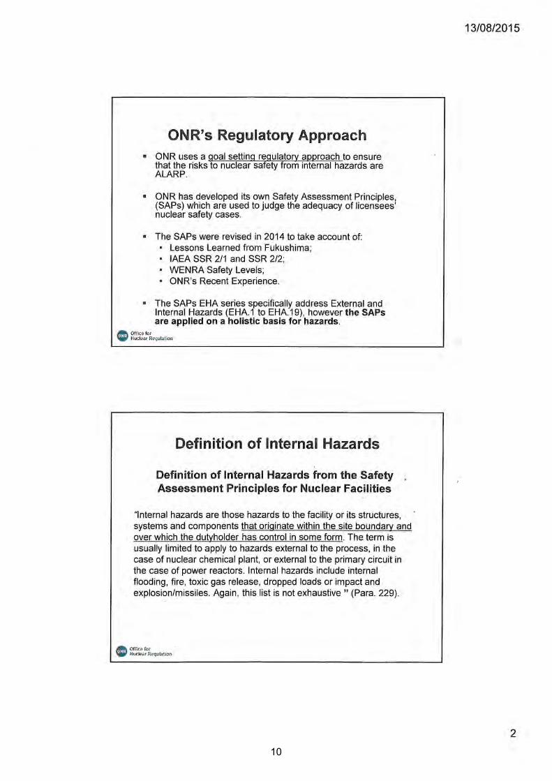
09:45 h Regulatory Expectations on Internal Hazards Assessment With Particular Focus on Fire
A. Alexiou ONR, United Kingdom
10:15 h Regulatory Point of View on Defence-in-depth Approach to Fire Protection in Nuclear Power Plants
S. Rinta-Filppula, et al.
STUK, Finland
10:45 h Coffee Break
11:15 h Recent Update of the German Nuclear Fire Protection Standards KTA 2101, Part 1 to 3
B. Elsche, M. Röwekamp W. Neugebauer
e.on Kernkraft, Germany GRS, Germany AREVA NP, Germany
12:00 h Recent Amendments in the KTA 2101.2 Fire Barrier Resistance Rating Method for German Nuclear Power Plants and Comparison to the Eurocode T-equivalent Method
B. Forell GRS, Germany
12:30 h Lunch Break
Regulation, Standards and Guidelines (continued)
Chairperson: G. Williams (ONR)
14:00 h Enhancements in PSA Regulation and Guidance on Fire Risk Analysis for Nuclear Power Plants
H.-P. Berg BfS, Germany
Fire Protection in the Design of Nuclear Installations
Chairperson: H.-P. Berg (Germany
14:30 h Internal Fire Protection Analysis for the United Kingdom EPR Design
A. Laïd, et al.
EDF NNB GenCo, United Kingdom
15:00 h Overview of Internal Fire Hazards As-pects of ABWR Design for United Kingdom
K. Yoshikawa, et al.
Hitachi-GE, Japan
15:30 h Coffee Break
5

16:00 h Passive Fire Protection: Role and Evolutions
T. Cerosky, et al.
Nuvia, France
16:30 h Recent Enhancements of the OECD FIRE Database
M. Roewekamp, M. Lehto
GRS, Germany STUK, Finland
17:00 h Adjourn of the first day
19:00 h Hosted Dinner All participants enscribed and spouses
Tuesday, August 18, 2015
Experimental Fire Research Chairperson: M. Röwekamp (Germany)
09:00 h Characterizing the Thermal Effects of High Energy Arc Faults
A. Putorti, et al. NIST, USA
09:30 h Assessment of the Burning Behaviour of Protected and Unprotected Cables and Cable Trays in Nuclear Installations Using Small- and Large-scale Experiments
M. Siemon, et al. iBMB, Germany
10:00 h Fully Predictive Simulations of Real-scale Cable Tray Fire Based on Small-scale Laboratory Experiments
F. Bonte, et al. BEL V, Belgium
10:30 h Coffee Break
Fire Safety Analysis and Modelling Chairperson: M. Röwekamp (Germany)
11:00 h Experimental and Numerical Study of Smoke Propagation Through a Vent Separating Two Mechanically Ventilated Rooms
L. Audouin, et al. IRSN, France
11:30 h Large Eddy Simulation of a Mechanically Ventilated Compartment Fire for Nuclear Applications
J. Wen, et al. University of Warwick, United Kingdom
12:00 h Global Sensitivity Analysis Using Emulators, With an Example Analysis of Large Fire Plumes Based on FDS Simulations
A. Kelsey HSL, United Kingdom
12:30 h Lunch Break
Fire Safety Analysis and Modelling (continued)
Chairperson: M. Röwekamp (Germany)
13:30 h Sensitivity Analysis of FDS 6 Results for Nuclear Power Plants
E. Puente, at al.
University of Cantabria, Spain
6
14:00 h Focus on the Studies in Support of Fire Safety Analysis: IRSN Modelling Approach for Nuclear Fuel Facilities
T. Vinot, et al. IRSN, France
Operating Experience and Lessons Learned
Chairperson: A. Alexiou (United Kingdom)
14:30 h Fire Analysis: Relevant Aspects from Spanish Nuclear Power Plants Experience
T. Villar Sánchez, P. Fernandez Ramos
Empresarios Agrupados, Spain
15:00 h Coffee Break
15.20 h The Human Dimension: Improving Fire Safety in Nuclear Power Plants by Improving Awareness of Fire Hazards and Influencing Behaviours
G. Williams, et al. ONR, United Kingdom
15:50 h Defence-In-Depth Strategy of Fire Protection and Its Relevance after Final Shutdown
M. Beesen TÜV SÜD, Germany
16:20 h Feedback from Recent Operating Experience in Nuclear Power Plants Regarding Fire Safety
B. Forell GRS, Germany
16:40 h Panel Discussion Chairperson: H.-P. Berg (Germany)
Panel participants: A. Alexiou H.-P. Berg L. Kuriene M. Röwekamp G. Williams
17:10 h Seminar Adjourn
7

3 Seminar Contributions
In the following, the seminar contributions prepared for the 14th International Seminar
on ‘Fire Safety in Nuclear Power Plants and Installations’ held as Post-conference
Seminar of the 23rd International Conference on Structural Mechanics In Reactor Tech-
nology (SMiRT 23) are provided in the order of their presentation in the seminar.
8

9
10
11
12

13

14

15
16
17

18

19

20

21

23rd International Conference on Structural Mechanics in Reactor Technology (SMiRT 23) - 14th
International Pre-Conference Seminar on “FIRE SAFETY IN NUCLEAR POWER PLANTS AND INSTALLATIONS“
REGULATORY POINT OF VIEW ON DEFENSE IN DEPTH APPROACH TO FIRE PROTECTION IN NUCLEAR POWER
PLANT
Samu Rinta-Filppula1, Matti Lehto1, Pekka Välikangas1
1 Radiation and Nuclear Safety Authority STUK, Helsinki, Finland ABSTRACT The defense-in-depth (DiD) principle is a relatively new approach to fire protection de-sign, even though DiD has been used in nuclear power plant (NPP) safety evaluation and design for decades (IAEA 75-INSAG-3, Rev. 1/INSAG-12). It is the main design criterion in fire protection in the latest edition of Finnish Radiation and Nuclear Safety Authority (STUK) issued guide YVL B.8 for the fire protection in nuclear facilities. The DiD approach to fire protection consists of four levels of defense: preventing the igni-tion of fires, detecting and extinguishing of ignited fires, preventing fire growth and spreading, confining the fire so that safety functions can be performed irrespective of the effects of the fire. The design of fire protection should take all these levels into ac-count so that fire protection is well balanced and not dependent on a single fire protec-tion factor or level of DiD. Despite being central to the design of fire protection, corresponding evaluations of DiD are done according to more or less unambiguous methods. The main goal of this study is to start the development of such, as much as possible, unambiguous systematic and logical method. First issue then is to build a picture of how fire safety features are exe-cuted on different levels of DiD and what is the corresponding safety importance to NPP. The Loviisa NPP was studied as an example case due to a long history of fire safety improvements since commissioning in 1977. The improvements are sorted quali-tatively by their means of fire safety impact and level of DiD approach to fire protection and general plant DiD. The correspondence between the two DiD principles is an inter-esting issue which is discussed in this paper. Finally, Fire PRA is used to determine the safety importance of the improvements. The method proposed for the evaluation of DiD approach to fire protection is a com-bined ignition root cause analysis – event tree of fire scenario – consequential failure modes and effects analysis (FMEA) where the three analyses are performed succes-sively for a given type of fire event. The challenge is to support experts focusing in cer-tain technical domain and exchanging relevant information between these analyses. Ignition root cause analysis is performed to find the factors leading to a fire event. Fire propagation is then modeled in the event tree, where fire protection features are taken into account. FMEA is then performed based on the fire scenario extracted from the event tree. The last stage also includes analysis on fire spreading. Measuring the effect of compartmentalization and fire spreading on safety is challenging. Accuracy of the analysis tools and initial values used in the example case is discussed. When the fire protection concept of new design is evaluated viewpoints are effects of failures and impairments in DiD on safety of the facility. For operating units viewpoints are the effects of improvements. The described method is focusing on the framework for evaluation of the DiD approach to fire protection, wherein the actual analysis tools are only discussed briefly using an example case.
22
INTRODUCTION Public opinion is hindering the prospects for commissioning new nuclear power plants (NPPs) to reduce the production of greenhouse gases via traditional fossil fuel fired power plants. One of the main concerns for people with negative perceptions about nu-clear power is nuclear safety. The recent Fukushima disaster is one of only three major accidents in the history of NPPs that have led to core degradation, but it’s fresh in the minds of people. The International Atomic Energy Agency (IAEA) promotes nuclear and radiation safety. It produces guidelines and demands to guarantee the safety of NPPs. All the member states, including Finland, adhere to these guidelines. The Finnish Radiation and Nucle-ar Safety Authority (STUK) is responsible for the oversight of NPPs in Finland. In addi-tion to the IAEA guidelines STUK has published its own YVL-guides which are stricter in many respects. Thorough design of plant processes and layout creates the basis for plant safety. It is guided by many safety principles given by IAEA. While nuclear safety is the main con-cern in the design and operation of NPPs, there will always remain a risk for an acci-dent. Fire events are a type of internal hazards that can compromise safety of a plant and lead to accidents. It is estimated that fire risk can comprise up to half [1] of the total core damage risk. Fire safety, too, is based on layout design. The separation of differ-ent safety systems and their redundancies reduces the risk considerably. Defense-in-depth (DiD) is a safety principle for NPPs [2], [3]. It means having several separate and independent barriers between hazard and severe accident. Even with one barrier failing, the next one should be able to prevent the situation from getting worse and eventually leading to the release of radioactive materials into the environ-ment. A barrier in this case can be considered a physical literal barrier or a safety sys-tem that for example helps to cool the reactor core. DiD approach can also be applied to fire protection, as defined later in this paper. STUK has added the term in the latest edition of its YVL-guide B.8 “Fire Protection at a Nuclear Facility” [4]. This guide also demands certain assessments of fire safety. As a new term, a universally validated method with acceptance criteria for assessing whether DiD for fire protection is ade-quate does not yet exist. The goal of this paper along with a broader master thesis [5] is to open the discussion and possible research in the field of this assessment. This paper along with master thesis looks retroactively into the Loviisa NPP and the fire safety improvements done there as an example case. In the first part, the improve-ments are filtered and classified according to their means of influence, whether they are structural or active improvements and which level of defense in depth they fall into. In the second part we research associated numerical values to improvements. Risk in-crease factors (RIF) derived from Fire PRA (Probabilistic Risk Assessment) are used for this part. Along with the classification it ca be determined which level of DiD for fire protection has been improved the most since the commissioning of the plant. The third part of the research took a closer look into the assessment of DiD. In this part, STUK started to develop a method for the assessment of possible acceptance criteria. DEFENSE-IN-DEPTH IN REGULATION Defense-in-depth is an essential safety principle in the design of NPPs. Assuring the effectiveness of DiD is done by multiple independent and redundant levels of defense and applying reliable materials and systems. In the Finnish regulation DiD is defined in STUK YVL-guide B.1 [6]. Safety functions shall be assured through five successive levels. The first two levels are designed to prevent accidents, whereas the remaining
23
ones are designed to protect the plant, operators and the environment from the ad-verse effects of an accident. The levels of DiD are:
1. Prevention 2. Control of anticipated operational occurrences 3. Control of accidents 4. Containment of release in a severe accident 5. Mitigation of consequences
The final objective for the DiD principle is to prevent releases of radioactive substances in excess of the limits set in Government Decree 717/2013 [7]. The defense-in-depth approach to fire protection can be considered as one of the many means for realizing defense-in-depth for the entire plant. As a term it is relatively new. It can be found in an official IAEA publication at least in 1992 [8]. (U.S. Nuclear Regulato-ry Commission (NRC) has mentioned the DiD approach to fire protection dating back to the 1980ies.) STUK included it in the new edition of YVL-guide B.8 “Fire Protection at a Nuclear Facility” in 2013 [4] as the main design principle. The four levels of DiD ap-proach to fire protection are:
a. Prevention of ignition of a fire, b. Rapid detection and extinguishing of ignited fires, c. Prevention of fire growth and spreading of a fire, d. Containment of a fire such that the facility’s safety functions can be reliably
performed irrespective of the effects of the fire [4]. The issues addressed in the levels of DiD are not new per se. The point of defense-in-depth is to bind together the basic principles for the design of fire protection. The new idea is the successive barrier point of view. It should be assured that even if one level of defense fails, others will ensure the safety of the plant. Prevention of ignition is the first level of the DiD approach with respect to fire protec-tion. Construction materials allowable for Class P1 buildings in accordance with the Na-tional Building Code of Finland (Parts E1 & E2) [9] are used to minimize the danger of ignition. Validated fire resistant materials must be used wherever possible. Electrical equipment and machines containing moving parts must be reliable. Some systems contain fluids (oils, hydrogen etc.) with low flashpoints. In spaces with such substances there should be leak detection systems and extra fire protection for the systems in question. The second level of the DiD approach to fire protection demands that a fire shall be de-tected and extinguished rapidly. Detection is done by an automatic system that encom-passes the whole plant. Fixed extinguishing systems should also encompass the whole plant, excluding justifiable exceptions. These have to be able to function automatically when needed. In addition, components with high fire loads can be protected with sepa-rate extinguishing systems. The third level of the DiD approach for fire protection addresses prevention of fire growth and spreading. Primary means are separation of buildings and fire compart-mentation. Compartmentation is done by storey (vertical compartmentation) and by use. Safety divisions shall be separated by structures having a fire resistance rating of at least EI-M 120 (120 min fire resistance). This includes doors and hatches which also have to be locked during normal plant operation. Other compartment boundaries must be established between spaces with different operational usages and for separating high fire loads. The separating structural elements shall fulfill the fire resistance class requirements of the National Building Code of Finland [9]. Other needs in order to pre-vent fire spreading are ventilation control and smoke extraction.
24

The fourth level of DiD approach to fire protection ensures the functionality of the plant despite the effects of a fire. Main control room and emergency control rooms shall be separated by locations safe from fire risks. They shall represent their own fire com-partments and they shall have isolated air conditioning systems. By our interpretation the fourth level of DiD approach to fire protection also handles functions that are im-plemented to improve plant safety, such as redundant systems and back-up power supply systems. There is an analogy between nuclear safety DiD principle and DiD approach with re-spect to fire protection. The design of NPPs is a complex process with all the safety guides and demands on top of the complexity of the nuclear process itself. Thus the links between different safety features may not seem clear to an outsider. Instinctively one might think that the fire protection part precedes the nuclear safety DiD concept so that when fire protection is taken care of there will be no initiating event or, if it fails, the problem simply moves to general plant safety. However, this is not the case. The rela-tions between the different levels of these two principles are intertwined. Basically it boils down to the following four questions: Can a fire in the compartment under investi-gation cause an initiating event? Are there components of safety systems that can be damaged by fire? Are there components of safety systems in the adjacent compart-ments? Can the fire event jeopardize performing of safety functions in any other way? This analysis yields a connection between all of the first three levels of DiD approach to fire protection and all of the first three levels of the nuclear safety DiD concept. In addi-tion, the fourth level of DiD of fire protection has a connection to levels 2-4 of the nu-clear safety DiD concept. Requirements for the Assessment of Fire Safety One of the main drivers for this research was the fact that DiD is the basis of fire pro-tection design, but there is no defined method for assessing it. STUK Guide YVL B.8 [4] states of assessment of fire safety: “To verify the adequate implementation of the defense in depth approach to fire protec-tion, the following fire hazard analyses shall be conducted: a. fire hazard analyses of the nuclear facility by deterministic, generally approved
and experimentally verified methods such as structural (FHA) and functional (FFHA, FHFA) fire hazard analyses fire simulation analyses to evaluate fire development and the ambient effects of
fire, temperature increase in particular, analyses of heating, load-bearing capacity and integrity of load-bearing and
separating structures analyses or calculations of temperature increase in the room or object of study,
such as component temperature increase b. in addition to the above, for a nuclear power plant, a probabilistic fire risk as-
sessment, a fire PRA (STUK Guide YVL A.7 [10]).”
All of these are separate analyses, which do not really answer the question of the ade-quacy of defense-in-depth. They are, however, great tools for assessing fire safety in general. Key attribute of successful DiD is balance. All the aspects must be taken into consider-ation and fire protection cannot rely on any single feature. According to STUK Guide YVL B.8 [4], when evaluating the implementation of the DiD approach to fire protection, one has to assume failures or impairments to plant fire protection, and remaining fire protection measures will have to compensate the deficiencies (e.g. failures to active fire protection measures and impairments to fire compartmentation, such as open fire
25
doors). Normally, all equipment in the fire compartment shall be assumed to fail due to a fire. This means that within a safety division several systems may fail, but adequate safety functions must be possible to perform in any case. The assumption of losing the entire compartment in case of fire gives conservative result of the analyses, but is inac-curate in assessing specific fire protection characteristics inside the compartment. RESEARCH METHODS AND GOALS As stated earlier, this paper digs into the DiD approach to fire protection in three phas-es. The study is limited to threats originating during power operation. First STUK did a qualitative classification of fire safety improvements completed at the Loviisa NPP. Then a quantitative study of the safety importance of the improvements and corre-sponding levels of the two principles of DiD was made. Finally, the third part of the study tackled the assessment methodology for the DiD approach to fire protection, which is the most important part with long-term implications. The case study of the Lov-iisa NPP differs from future uses of this assessment technique: At first improvements were studied retrospectively, whereas in the future the targets shall be specific factors contributing to characteristics of a fire protection concept, when the concept is to be approved for new plants. Classification of Improvements In the first part of the research, the fire safety improvements connected to the turbine hall of the Loviisa NPP were studied and assessed in the cadre of defense-in-depth. Improvements were picked out from the internal STUK report ‘Safety Improvements of Loviisa NPP’. In this part, the improvements were classified by their attributes. Means of fire safety impact were determined at first. Based on that, improvements were sorted to structural and active fire protection and further on different levels of DiD regarding both fire protection and plant safety. The goal of this classification was to get a com-mon understanding of the improvement landscape and to see if some aspects of fire protection are being over- or underrepresented. This also provided some information on the relationship between the two principles of DiD. Probabilistic Study The second part of the study assigned credit to the improvements’ impact on fire safe-ty. The source material for this part was the Fire PRA of the Loviisa NPP. The Fire PRA was categorized by fire induced initiating events (IE), which were defined separately for each fire compartment (or room) and fire spreading events and given as input for the fire scenarios in the Fire PRA model. Therefore, the Fire PRA model did not show the failure combinations leading to different IEs. These IEs lead to core damage according to minimal cut sets (MCS) containing also the unavailability of safety systems needed to mitigate the IE in question. Along with the fire scenario frequency this gives the core damage frequency (CDF) caused by the fire according to each MCS. Rooms of the plant are analyzed in the Fire PRA based on the IEs identified which are possibly induced by fires, the fire scenarios defined, and the possible fire induced fail-ures of components and cables of systems that are needed to mitigate the IE identified. In case a fire in a room can induce different IEs, their combinations need to be handled as well. Based on this knowledge, the safety improvements are sought from the Fire PRA data and their value to fire safety can be determined. The results from the first part are uti-
26
lized in grouping the quantifiable credit the improvements get on different levels of DiD. The importance of different improvements is derived from Fire PRA results as risk in-crease factors (RIF). The second research phase tells us if one improvement or aspect of DiD is superior in impact compared to others. This is important, as it is required from DiD to be balanced. Assessment of the Defense-in-depth Approach for Fire Protection In the final part of the research, the discussion about assessing DiD approach to fire protection has been opened A three-step method is proposed. It consists of ignition root cause analysis, fire event tree analysis and consequential failure modes and ef-fects analysis (FMEA). The three analyses are performed successively for a given fire scenario with the goal of identifying the significance of all the fire protection features. The three-step way of thinking is providing the framework where the different aspects of DiD can be quantitatively compared to each other. The actual analysis tools utilized in this method are nothing new, but are utilized mostly as stand-alone analyses of cer-tain specific issues. This method has been first applied to the assessment of an oil pool fire in the turbine hall of the Loviisa NPP in the accompanying master thesis [5], which will be published in the near future, at first in Finnish. The ultimate goal of the research started is to have an assessment method, which is universal and has clearly defined acceptance criteria for the DiD approach with respect to fire protection. For now, until a universal method is developed, DiD is evaluated too subjectively. It has been recognized that, in the frame of our study we probably would not meet this goal, but even to nudge the research in the right direction and open the scientific debate would be sufficient. CASE STUDY: LOVIISA NUCLEAR POWER PLANT The Loviisa NPP constitutes of two modified VVER-440/230 reactors commissioned in 1977 and 1980. The reactors have been uprated and currently produce at 510 MWe each. Loviisa NPP is unique in design because the Soviet VVER-440/230 type reactors did not fulfill the Finnish safety regulations as they were. Additional safety features and Western technology were applied to the original Soviet design configuration. The plant still contained safety shortcomings at the time of commissioning, which led to needs for safety improvements. The shortcomings were largely due to weaknesses in layout design, but the low grade of redundancy and diversity was also a problem. With the modifications, the plant became more complex. There are two safety trains for most of the safety systems, although some active components are doubled. Spatial separa-tion of systems and compartmentation were partially incomplete and cable routings of the two redundancies could not be fully separated throughout the plant. These factors obviously increase the fire risk, for example the feedwater systems were vulnerable and could be lost in a fire event in the turbine hall. The turbine hall was chosen as the primary subject for the research by STUK. Turbine Hall The turbine hall contains four turbine generators, two for each reactor unit. In the origi-nal layout, the turbine hall and the feedwater tank compartment, which is located on an upper floor compared to the turbines, formed a common fire compartment. One of the main fire safety improvements of the entire plant has been the construction of a fire wall (called upper part of B-line wall) to separate the feedwater compartment from the
27

turbine hall. The original lower part of the B-line wall also protects the control building from turbine hall fire events. Still, the remainder of the turbine hall contains safety relat-ed equipment and a fire in the turbine hall poses a threat to plant safety. Three connec-tions between turbine hall, feedwater tank compartment and control building has been studied in the frame of fire safety improvements. The main fire loads in the turbine hall consist of oil in the turbine lubrication and control systems, hydrogen used for cooling the generator and cable insulations. Hydrogen also carries a risk of explosion. Main ignition sources are hot surfaces, electric equipment and rotating machines. The turbine hall poses a problem to fire protection design as the complex layout includes several floors below the main floor where the turbines are lo-cated. In case of an oil leak, the oil could flow down to all floors and spread along the floors. QUALITATIVE ASSESSMENT OF SAFETY IMPROVEMENTS The first phase of the research was the classification of already completed fire safety improvements in the Loviisa NPP. The pertinent improvements were filtered according to the following sections: “Fire safety and fire protection”, “Feed water and steam sys-tems”, “Floods and pipe ruptures” and “Other Issues”. Every improvement being in, or in the vicinity of the turbine hall and the main control room was picked from the STUK’s internal report ‘Fire safety and fire protection’ along with improvements that affect the whole plant. Fire safety improvements arising from “Feed water and steam systems” are not very obvious, but the logic is that building or improving redundant or back-up systems for systems located inside the turbine hall or the feedwater tank compartment are also considered for fire safety improvements. Improvements to flooding protection are taken into account if they are clearly designed against flooding caused by fire ex-tinguishing systems. “Other Issues” contains few improvements to the main control room conditions, which are also within the scope. Improvements to the auxiliary sys-tems are omitted. 46 fire safety improvements were identified to be analyzed. Results Filtered improvements were classified according to means of fire safety impact, to structural and active improvements and on the levels of nuclear safety DiD and fire pro-tection DiD. The amount of improvements assigned to each means of impact is pre-sented in Table 1. The means of impact are listed in different DiD levels, however it shall be noted that means can in fact appear on multiple levels. Such means include but are not limited to local fire protection and increasing distance. The means of impact covered all of the improvements in this study, but there can be others, which are not associated with these improvements. Some improvements are challenging to be classi-fied because they are bigger entities impacting many factors. These are thus assigned relevant means of impact in Table 1. The most frequent means of fire safety impact are improving fire extinguishing (15 times) and fire insulation (7). The first four entries to “Preventing fire growth and spreading” could also be grouped together as physical separation, which would then be the most common means. Based on previous classification and the more detailed descriptions, the improvements are divided to structural and active ones by their fire protection function. Two of the im-provements belong in both categories, while some are difficult to assign to either class. There are 22 structural and 26 active fire safety improvements.
28
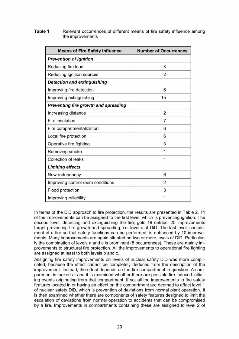
Table 1 Relevant occurrences of different means of fire safety influence among the improvements
Means of Fire Safety Influence Number of Occurrences
Prevention of ignition
Reducing fire load 3
Reducing ignition sources 2
Detection and extinguishing
Improving fire detection 6
Improving extinguishing 15
Preventing fire growth and spreading
Increasing distance 2
Fire insulation 7
Fire compartmentalization 6
Local fire protection 6
Operative fire fighting 3
Removing smoke 1
Collection of leaks 1
Limiting effects
New redundancy 6
Improving control room conditions 2
Flood protection 3
Improving reliability 1
In terms of the DiD approach to fire protection, the results are presented in Table 2. 11 of the improvements can be assigned to the first level, which is preventing ignition. The second level, detecting and extinguishing the fire, gets 19 entries. 25 improvements target preventing fire growth and spreading, i.e. level c of DiD. The last level, contain-ment of a fire so that safety functions can be performed, is enhanced by 10 improve-ments. Many improvements are again situated on two or more levels of DiD. Particular-ly the combination of levels a and c is prominent (8 occurrences). These are mainly im-provements to structural fire protection. All the improvements to operational fire fighting are assigned at least to both levels b and c. Assigning fire safety improvements on levels of nuclear safety DiD was more compli-cated, because the effect cannot be completely deduced from the description of the improvement. Instead, the effect depends on the fire compartment in question. A com-partment is looked at and it is examined whether there are possible fire induced initiat-ing events originating from that compartment. If so, all the improvements to fire safety features located in or having an effect on the compartment are deemed to affect level 1 of nuclear safety DiD, which is prevention of deviations from normal plant operation. It is then examined whether there are components of safety features designed to limit the escalation of deviations from normal operation to accidents that can be compromised by a fire. Improvements in compartments containing these are assigned to level 2 of
29
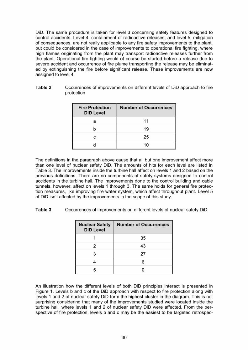
DiD. The same procedure is taken for level 3 concerning safety features designed to control accidents. Level 4, containment of radioactive releases, and level 5, mitigation of consequences, are not really applicable to any fire safety improvements to the plant, but could be considered in the case of improvements to operational fire fighting, where high flames originating from the plant may transport radioactive releases further from the plant. Operational fire fighting would of course be started before a release due to severe accident and occurrence of fire plume transporting the release may be eliminat-ed by extinguishing the fire before significant release. These improvements are now assigned to level 4. Table 2 Occurrences of improvements on different levels of DiD approach to fire
protection
Fire Protection DiD Level
Number of Occurrences
a 11
b 19
c 25
d 10
The definitions in the paragraph above cause that all but one improvement affect more than one level of nuclear safety DiD. The amounts of hits for each level are listed in Table 3. The improvements inside the turbine hall affect on levels 1 and 2 based on the previous definitions. There are no components of safety systems designed to control accidents in the turbine hall. The improvements done to the control building and cable tunnels, however, affect on levels 1 through 3. The same holds for general fire protec-tion measures, like improving fire water system, which affect throughout plant. Level 5 of DiD isn’t affected by the improvements in the scope of this study. Table 3 Occurrences of improvements on different levels of nuclear safety DiD
Nuclear Safety DiD Level
Number of Occurrences
1 35
2 43
3 27
4 6
5 0
An illustration how the different levels of both DiD principles interact is presented in Figure 1. Levels b and c of the DiD approach with respect to fire protection along with levels 1 and 2 of nuclear safety DiD form the highest cluster in the diagram. This is not surprising considering that many of the improvements studied were located inside the turbine hall, where levels 1 and 2 of nuclear safety DiD were affected. From the per-spective of fire protection, levels b and c may be the easiest to be targeted retrospec-
30

tively. Level a is mainly inherent in the early material choices and layout, and level d is in part concise, in part very expensive to improve. Given the explanations of how the improvements are slotted to different levels of DiD principles, everything stated in this paragraph may actually be trivial, but we wanted to show the illustration nonetheless. The distribution of cross-matches would probably change dramatically when dealing with another compartment inside the plant, and also when targeting fire protection fea-tures in the design phase as opposed to the improvements of our example case.
Figure 1 Illustration of how often any given two levels of the different principles of
defense in depth are assigned to the same safety improvement QUANTITATIVE ASSESSMENT OF SAFETY IMPROVEMENTS This part of the study focuses on quantifying the importance of fire safety factors. This was done to enable comparison between the importance of different levels of DiD. The data sets studied are the improvements classified in the previous paragraph. The Fire PRA model of the Loviisa NPP serves as the source material. The model was run three times: First for fire induced core damage frequency (CDF) according to the basic Fire PRA, second for fire induced CDF in case that the additional emergency feedwater system is disabled, and third for CDF originating only from fires in the turbine hall and the feedwater tank compartment. The fire induced CDF is the overall frequency for min-imal cut sets (MCS) of basic events that lead to core damage combined to initiating events caused by fire scenarios with given frequencies. The three data sets are used to determine the importance of different fire safety improvements. The measure of im-portance used is the risk increase factor (RIF), which determines the increase factor for CDF in case of the basic event being failed. RIFs are calculated by the PRA code and part of the available source material mentioned above. The analyses are based on the latest Fire PRA model and the plant is considered to have been in current state when the historical improvements were made. The comparison between different versions of PRA is not sensible because, in addition to the improvement in question, there have possibly been many other changes to plant conditions, and even if not, the unavailabil-ity for basic events may have changed due to advances in the reliability data. Another underlying factor that has changed over time is the ignition frequency, which has been adjusted over the years. The fact that the first Fire PRA version for the Loviisa NPP was completed in 1997, about 20 years after the commissioning of the first unit, where-as the first safety improvements date back to right after commissioning also makes the above mentioned comparison impossible. In addition to using RIFs calculated by the PRA code, the importance of some im-provements is estimated through expert analysis. This is meant to give an idea of the
ab
cd
0
20
40
1
3
5
a
b
c
d
31

magnitude of RIFs for improvements that cannot be assessed just by a single basic event in the PRA model. Results The impacts of four stand-alone improvements could be assessed by the available PRA data, as shown in Table 4. Table 4 Risk increase factors (RIFs) for safety improvements (values in this table
are directly from the Fire PRA model)
RIFs for the improvements range from very small (1.02) for the back-up feedwater sup-ply system (based on the make-up system) to very large (42.6) for the additional emer-gency feedwater system (AEFW). The AEFW backs up the feedwater systems that are located inside the turbine hall and are thus susceptible to failure in case of fire in the turbine hall. The AEFW is one of the main safety improvements done at the Loviisa NPP. The RIF for the back-up feedwater supply system is very small, in part because AEFW, which was commissioned later, performs the same safety functions with higher availability. If there was no AEFW, the RIF of the back-up feedwater supply system would increase. Fire protection of safety system cables and electric components has a RIF of 1.64, while new hydraulic pipelines along with extinguishing systems for turbine bypass valve actuators have a RIF of 3.78. The new pipelines with protective casings practically eliminate oil spray fires and resulting oil pool fires can be extinguished with the sprinkler systems. In addition to the four improvements discussed above, the im-provements to operative fire fighting were grouped together to get a RIF value for them. The impact of individual improvements to operational fire fighting could not be deter-
Safety Improvement Level of DiD for Fire Protection
Level of DiD for Nuclear Safety
RIF
1 2 3 4 5
Back-up feedwater supply system x
x x
1.02
Fire protection of safety system electric components and cables x x x x
1.64
Additional emergency feedwater system x
x x
42.6
New hydraulic pipelines and local fire extinguishing systems for turbine bypass valve actuators
x x x x x
3.78
Establishing professional plant fire brigade x x x x x x
1.831) New fire truck for the fire brigade x x
x x
Back-up fire water pump station x x x x x x
New fire and rescue station x x x x x x
1) RIF from the third calculation that only takes into account fires in the turbine hall and the feedwater tank compartment; other RIFs are compared to the overall fire risk
32

mined, but as a whole the CDF of fires originating from turbine hall or feedwater tank compartment would be 1.83 times higher without plant fire brigade actions. The recent Fire PRA model does not go into detail regarding the impact of many safety improvements completed in the past. We wanted to expand the assessment to get an order of magnitude for the improvements in general and to be able to compare it to the few actual numbers derived straight from the PRA data. In Table 5, RIFs of some im-provements are acquired through expert analysis. These RIFs are acquired through comparing different versions of PRA models, comparing the improvements to similar features in the model and other calculations. The verbal assessments are rough esti-mates. All in all, the part of the analysis where we were supposed to compare impacts of dif-ferent levels of DiD could not be completed due to lack of appropriate data. However, it can be stated that few major improvements dominate the overall impact of the im-provements in this study. The most important safety improvements are the AEFW sys-tem, the B-line fire wall and sprinkler systems in the turbine hall. The main impacts of all of these improvements are on different levels of the DiD approach with respect to fire protection. Table 5 Risk increase factors (RIFs) for safety improvements (values in this table
are estimates acquired through expert analysis)
Safety Improvement Level of DiD for Fire Pro-
tection
Level of DiD for Nuclear Safety
RIF
1 2 3 4 5
Additional cooling system of emergency feedwater pump compartments
x x x small
Replacement of emergency feedwater pumps x x x small
Sprinkler systems to turbine hall and feedwater tank compartment x x x x x large
New fire wall to separate feedwater tank compartments from turbine hall (B-line)
x x x x large
Safety systems cables rerouting and fire protection in the turbine hall x x x x moderate
Generator nitrogen supply system renewal x x x x very
small Modernization of sprinklers in the turbine hall x x x small
Some fire doors walled up in the turbine hall x x x moderate
33
METHOD FOR ASSESSING DEFENCE-IN-DEPTH APPROACH TO FIRE PROTECTION The goal was to create a method that can be used to assess the DiD approach for fire protection as a whole, while still taking into account even the smallest fire protection features. Main point of interest was the balance of fire protection features on different levels of DiD. Therefore, a three-step method is proposed for analyzing a set of fire scenarios in a fire compartment:
Ignition root cause analysis, Event tree analysis of the fire scenario, Consequential failure modes and effects analysis (FMEA).
The analysis is not far away from Fire PRA analysis, but it aims for a higher level of ac-curacy with respect to the effects of fire protection measures and the consequences of a fire. The advantages of this method include the possibility to have all fire scenarios originating from the same compartment assessed in same analysis. It is also a way of bringing expertise from various fields together and interconnecting it in the same analy-sis. Main challenges are the transmission of information from one step to another and the fact that the analysis may expand to the point where it is difficult to maintain under-standing of the big picture and control all the variables affecting the fire scenario. This method is mainly a framework, wherein the actual analysis tools may still need devel-oping. In the following paragraphs the current ideas for the in-depth analysis are de-scribed. Ignition Root Cause Analysis Ignition root cause analysis takes into account all the factors impacting the ignition of a fire. For some type of fires this can be very straightforward, while for others, such as the case of oil fire in the turbine hall, it is complex. The proposed way to do this analy-sis is a fault tree or an event tree, depending on the fire scenario to be investigated. Frequencies are assigned to events that can cause an ignition and probabilities to fail-ures of fire protection measures aiming to prevent ignitions. The result of this analysis should be a frequency of a fire of a certain initial burning rate. In more complex cases, the result should be a distribution of frequencies for a set of fires of different initial burn-ing rates. The latter is e.g. used in the case of oil pool fire. This analysis encompasses level a of DiD. Event Tree Analysis of the Fire Scenario Event tree analysis starts with ignition and includes all the fire protection measures in-side the fire compartment. It describes the development and growth of the fire depend-ing on the initial burning rate and different fire protection measures taken. The result should be a set of temperature fields inside the compartment each with assigned condi-tional probabilities depending on the path the fire took along the event tree. To be able to find the temperature fields, a CFD fire simulation or rather a set of simulations of fire in the compartment must be performed. Probabilistic Fire Simulator (PFS) developed by Hostikka [11] is proposed as one of the tools to be used. The results of the simula-tions are then scaled for different initial burning rates, taking into account the fire pro-tection measures actuated. The event tree of the fire scenario encompasses level b of DiD completely and fire growth part of level c.
34
Consequential Failure Mode and Effects Analysis (FMEA) The final part of the assessment method tackles the question what exactly happens to the plant as a consequence of a compartment fire. Based on the temperature field in the compartment determined in the previous part, it is examined whether components of safety systems are affected by the fire either in the compartment or in adjacent com-partments, if the temperature penetrates through structures. Possible impacts to struc-tures are assessed as well. Finally, an analysis of fire spreading is performed. Spread-ing can happen as a result of structures failing due to fire or via open fire doors or other orifices. The effect of compartmentation is difficult to quantify. To keep the scope of the analysis feasible, event tree analysis is not applied to fire spreading events, but rather the compartment is directly assumed to be lost. After completing these tasks, the anal-ysis continues as PRA to assess the conditional core damage probabilities and CDFs for different fire scenarios with all the failures found within the FMEA. CONCLUSIONS It has been concluded that it is possible to classify fire safety improvements according to different criteria. Similarly, fire protection features of a new NPP could be assessed. This information is useful and should be considered when assessing the implementa-tion of the DiD approach to fire protection. In the example case of the turbine hall of the Loviisa NPP, the distribution of improvements on different levels of the DiD approach for fire protection was a little imbalanced, which was expected, because some fire pro-tection features are easier to be improved than others, and some aspects of fire safety have already adequately been taken into account. The comparison of matches be-tween the two principles of DiD may possibly be utilized to identify compartments which need to be improved from the viewpoint of nuclear safety. Probabilistic analysis of the historical safety improvements utilizing the current Fire PRA model did not yield the desired results. Risk increase factors could be directly de-fined for only a handful of improvements based on the actual Fire PRA model. Due to this, the comparison of the importance of the different levels of DiD was dropped com-pletely from this paper. Through the data and expert analysis, the most important im-provements are seen to be the additional emergency feedwater system, the B-line fire wall and the sprinkler systems in the turbine hall. The problem with analyzing historical improvements is that the current Fire PRA model does not include different fire protec-tion configurations through the past years. The lack of data was in part due to the insignificance of the improvements or the diffi-culty to quantify them, but more about the nature of PRA model. To an outside observ-er it shows the initiating events and fire scenarios that lead to core damage, but not the failures leading to initiating events. Some features of the plant are excluded from PRA due to conservative assumptions. Fire PRA also considers a fire compartment com-pletely lost in many cases even when that does not constitute more than a minor risk to the overall nuclear safety of the plant. Thus, no credit has been given to some local fire protection measures designed to prevent spreading of fire inside a compartment. The shortcoming of PRA for precise modeling only highlights the problem at hand: how to assess the DiD approach with respect to fire protection. In the Finnish regulation, examples of analytical tools for assessing defense–in-depth are given. However, these are singular methods that do not aim to quantify the balance of DiD levels. Our goal was to create a method for assessing the entirety of a given fire scenario in a compartment. A three-step method with ignition root cause analysis, event tree of a fire scenario, and consequential failure modes and effects analysis is proposed. Data is transferred and shaped throughout the analysis as a continuum, so that factors impacting fire safety can be measured on the same scale. The method re-
35

sembles PRA in that probabilities are assigned to all the basic events along the way. Where the analysis differs from PRA, is that there’s also a variable for the severity of the fire alongside the probability. In the beginning it is the burning rate, which goes through changes depending on fire propagation and is then transformed into a temper-ature field inside the compartment by means of fire simulations. The challenges for this method include complexity, which can make analysis arduous. Using different experts for each step eases this issue, but creates another. Now every step has to be defined extra carefully at the interface and the quality of information transmitted has to be very dependable. Our method has not been finalized yet to use, so the second goal of defining ac-ceptance criteria would have been difficult to achieve. However, two types of criteria can be identified: fire safety and balanced DiD. The balance of DiD can be analyzed separately or just by assuming all kinds of failures and impairments to fire protection features and then assessing fire safety. This can be done conveniently within the as-sessment method as both ignition root cause analysis and event tree analysis are in a form, where a fire protection feature either succeeds or fails and it is possible to as-sume failure in every case. Even in the FMEA analysis which continues toward core damage as PRA and spreading analysis these failures and impairments can be as-sumed. So far this method seems promising, however needs to be finalized and enhanced. The first complete version with an example case of the Loviisa NPP turbine hall will be pre-sented in the accompanying master thesis during this fall including a first proposal of acceptance criteria. REFERENCES [1] Grobe, J., Transcript of Nuclear Regulatory Commission Briefing on Fire Protec-
tion Issues, United States Nuclear Regulatory Commission (USNRC), July 17, 2008, p. 58.
[2] International Atomic Energy Agency (IAEA), Basic Safety Principles for Nuclear Power Plants, 75-INSAG-3 Rev. 1, INSAG-12, Vienna, Austria, October 1999, http://www-pub.iaea.org/MTCD/publications/PDF/P082_scr.pdf.
[3] International Atomic Energy Agency (IAEA), Defence in Depth in Nuclear Safety, INSAG-10, Vienna, Austria, June 1996, http://www-pub.iaea.org/MTCD/publications/PDF/Pub1013e_web.pdf.
[4] STUK, Guide YVL B.8 Fire Protection at a Nuclear Facility, Helsinki, 2013, http://www.finlex.fi/data/normit/41792-YVL_B.8e.pdf.
[5] Rinta-Filppula, S., Ydinvoimalaitosten palontorjunnan syvyyspuolustusperiaatteen arviointi (Assessment of Defense in Depth Approach to Fire Protection in Nuclear Power Plants), master thesis, in preparation 2015.
[6] STUK, Guide YVL B.1 Safety Design of a Nuclear Power Plant, Helsinki, 2013, http://www.finlex.fi/data/normit/41774-YVL_B.1e.pdf.
[7] Ministry of Employment and the Economy, Finland, Government Decree on the Safety of Nuclear Power Plants 717/2013, Helsinki, Finland, 2013, https://www.finlex.fi/en/laki/kaannokset/2013/en20130717.pdf.
[8] International Atomic Energy Agency (IAEA), Fire Protection in Nuclear Power Plants: A Safety Guide, 50-SG-D2, IAEA, Vienna, Austria, 1992.
[9] Ministry of the Envirionment, National Building Code of Finland (Parts E1 & E2), Helsinki, Finland, 2005 and 2011, http://www.ym.fi/fi-FI/Maankaytto_ja_rakentaminen/Lainsaadanto_ja_ohjeet/Rakentamismaarayskokoelma/The_National_Building_Code_of_Finland%2810420%29
36

[10] STUK, Guide YVL A.7 Probabilistic Risk Assessment and Risk Management of a Nuclear Power Plant, Helsinki, 2013, http://www.finlex.fi/data/normit/41813-YVL_A.7e.pdf.
[11] Hostikka, S., Development of fire simulation models for radiative heat transfer and probabilistic risk assessment, VTT Technical Research Centre of Finland, 2008.
37

23rd International Conference on Structural Mechanics in Reactor Technology (SMiRT 23) - 14th
International Post-Conference Seminar on “FIRE SAFETY IN NUCLEAR POWER PLANTS AND INSTALLATIONS“
ONGOING ENHANCEMENTS IN THE GERMAN NUCLEAR REGULATORY FRAMEWOK WITH RESPECT TO FIRE SAFETY
Björn Elsche 1, Marina Röwekamp 2, Wilfried Neugebauer 3, Rainer Gersinska 4
1 e.on Kernkraft, Hannover, Germany
2 Gesellschaft für Anlagen- und Reaktorsicherheit (GRS) gGmbH, Köln, Germany
3 AREVA NP, Erlangen, Germany
4 Bundesamt für Strahlenschutz (BfS), KTA-Geschäftsstelle, Salzgitter, Germany
ABSTRACT In the recent past, the regulatory framework for nuclear power plants (NPP) in Germany has been updated and enhanced comprising on the one hand comprehensive high level regula-tory documents such as the ‘Safety Requirements for Nuclear Power Plants’ and, on the other hand, revised state-of-the-art nuclear safety standards and rules being incorporated in a corresponding legal structure. A major enhancement concerns the nuclear fire and explosion protection standards being al-ready available as so-called green print for final comments which are expected to be official-ly published end of 2015. The update became necessary after approx. ten years for better addressing some lessons learnt form the operating experience, the consideration of post-Fukushima insights, such as more systematically addressing event combinations with fires and taking into account deviations from non-nuclear standards for escape and rescue routes. Moreover, fire protections remains an important issue for nuclear power plants in Germany during the longer term post-commercial safe shutdown period before decommis-sioning during which the spent fuel elements remain either in the containment or in the spent fuel pool for further years requiring suitable fire protection means being in place. INTRODUCTION In principle, the regulatory framework for nuclear power plants (NPP) in Germany is based on deterministic requirements supplemented by probabilistic ones for safety assessment. The regulation comprises high level comprehensive claims such as the most recent “Safety Requirements for Nuclear Power Plants” [1] as well as lower level detailed technical nuclear safety standards and rules incorporated in a corresponding pyramid type legal structure as shown in Figure 1 (from [2]). For German nuclear power plants, a variety of such technical nuclear safety standards pro-vided by the Nuclear Safety Standards Commission (German: Kerntechnischer Ausschuss, KTA) do exist, covering also fire and explosion protection. These standards promulgated in 2000 [3] to [6] have been recently revised for updating and enhancing them according to the state-of-the-art covering lessons learned from the post-Fukushima stress tests and investi-gations but also the specific German situation with several reactor units having stopped commercial operation being in a longer duration post-commercial safe shutdown plant op-erational state before decommissioning.
38

Figure 1 Nuclear regulatory framework in Germany (from [2]) All the three KTA fire protection standards as well as the explosion protection standard have already been published end of 2014 as s-called “green print” draft for final comments. Meanwhile, these final comments have been considered. It is expected that the standards will be finally published until the end of 2015. On the level of technically detailed KTA stand-ards in total four standards are available as green print drafts with respect to fire and explo-sion safety:
• KTA 2101.1: Fire Protection in Nuclear Power Plants, Part 1: Basic Requirements [7], • KTA 2101.2: Fire Protection in Nuclear Power Plants, Part 2: Fire Protection of Structur-
al Plant Components [4], • KTA 2101.3: (Fire Protection in Nuclear Power Plants, Part 2: Fire Protection of Mechan-
ical and Electrical Components [9], and • KTA 2103: Explosion Protection in Nuclear Power Plants with Light Water Reactor [10].
According to the most recent German regulation, the “Safety Requirements to Nuclear Pow-er Plants” [1] addressing also an adequate consideration of internal hazards including fires, the fire protection standards have to be applied to land based light water reactors for all plant operating phases from the construction phase, all plant operational states of commercial op-eration covering power operation as well as low power and shutdown states up to the last operational phase before decommissioning, the – at least in Germany partially some years long period – post-commercial safe shutdown phase. The standard may be as far as possi-ble also applied during decommissioning. The following nuclear protection goals and radiological safety goals have to be met:
- control of reactivity, - fuel cooling, - confinement of radioactive materials. - limiting radiation exposures.
Details with regard to the actual enhancements in the KTA fire protection standards are pro-vided in the following sections.
Basic Law
Atomic Energy Act
Ordinances
General administrative provisions
BMU publications
- Safety Requirements for NPP
- Guidelines and recommendations
RSK Guidelines, RSK and SSK recommendations
KTA Safety Standards
Technical specifications for components and systems Organisation and operating manuals
Federal legislator
Federal Government, Federal Council
Federal Government, Länder authorities
Advisory bodies
KTA
Industry
generally binding binding for authorities binding by specification in the licence or by supervisory measures in the individual case
39

NUCLEAR SAFETY STANDARD KTA 2101: FIRE PROTECTION IN NUCLEAR POWER PLANTS The German nuclear fire safety standards of the German Safety Standards Commission (KTA), KTA 2101 “Fire Protection in Nuclear Power Plants”, Parts 1-3 have been recently updated and enhanced All the three parts of KTA 2101 are interrelated (cf. Figure 2). Therefore, one intention of the update is to harmonize the structure to provide the fundamental requirements in Part 1 and the technical details for design and operation of structures, systems and components with respect to fire safety in Part 2 and 3 accordingly, avoiding duplications.
Figure 2 Interrelation of German nuclear safety standards KTA 2101 “Fire Protection in
Nuclear Power Plants”, Parts 1 to 3 Major goals of the update of KTA 2101, Parts 1 to 3 were the following: • Updating requirements to the actual state-of-the-art:
− corresponding to the most recent, also non-nuclear standards and norms, − providing specific compliance with requirements regarding the fire brigade, − considering low power and shutdown plant operational states better and more sys-
tematically, − addressing the fire hazard analysis explicitly and in a systematic way, − considering nuclear specific deviations from non-nuclear standards and norms with
regard to escape and recue routes, − covering event combinations of fires and other anticipated events more systemati-
cally as a lesson learned from the Fukushima Dai-ichi reactor accidents in 2011. • Compliance with the (new) “Safety Requirements for NPP” [1] in respect of the following
aspects: − Better consideration of the defence-in-depth concept, including specific compliance
with requirements for the safety demonstration, in particular requiring a fire protec-tion concept (sometimes in the international framework also called fire protection programme) and a systematic and comprehensively documented deterministic fire hazard analysis (FHA) being kept up to date,
− a more systematic approach and outline of the standards covering nuclear specific requirements and deviations from non-nuclear standards and norms,
KTA 2101.1Basic Requirements
KTA 2101.3Fire Protection of Mechanical and Electrical Plant Components
KTA 2101.2Fire Protection of Structu ral Plant
Components
40

− a systematic and comprehensive consideration of event combinations of fires with other anticipated event that have to be assumed, either occurring as consequence of the initial event or if their occurrence at the same time has to be accounted for due to their occurrence frequency and the extent of damage. In this context, the fol-lowing event combinations have to be considered: − Combinations of causally related events:
− Fire and consequential event, − Anticipated event and consequential fire,
− Fire and independently occurring anticipated event. KTA 2101.1: FIRE PROTECTION IN NUCLEAR POWER PLANTS – BASIC PRINCIPLES For consistency with international requirements, in particular from IAEA (International Atomic Energy Agency) and WENRA (Western European Nuclear Regulators Association), several existing requirements have been formulated more precisely or new requirements have been added. According to the fact that fire and explosion are often dealt with together in many interna-tional standards and guidelines (e.g. IAEA, United Kingdom, etc.) it has been clearly stated in KTA 2101 that requirements on explosion protection are provided in KTA 2103 “Explosion Protection in Nuclear Power Plants with Light Water Reactors” [10]. The Section on applications of the standard provides precise guidance on the goals of the standard KTA 2101.1. The following requirements are given: (1) This standard is applicable to nuclear power plants with light water reactors. (2) The standard is valid for all plant operational phases
a) for protecting those plant components needed in order to maintain their required functions for meeting the nuclear protection goals and radiologic safety goals ac-cording to the Safety Requirements for Nuclear Power Plants [1], par. 2.3 and 2.5:
aa) Control of reactivity, ab) Fuel element cooling, ac) Confinement of radioactive materials, and ad) Limiting radiation exposures as well as
b) for protecting humans working there in case of building-internal and building-external fires on site.
Note: In this context the term ‘plant component ‘ is used as follows according to [1]: Any structural, mechan-ical, process-based, electrical or other technical part of a plant. Synonyms are: equipment, system (see also structures, systems and components). One of the most important changes in the standard affects the protection against combina-tions of fires and other anticipated events. The systematically structures requirements are the following:
“3.3 Combinations of Fires with other Anticipated Events 3.3.1. Basic Principles (1) Combinations of fires with other anticipated events have to be assumed, if the events to
be combined are causally related or if their occurrence at the same time has to be ac-counted for due to their occurrence frequency and the extent of damage.
41
(2) Combinations of fires with other anticipated events have to be solely considered with re-spect to meeting the goals mentioned in Section 1, Paragraph (2) item a).For the combi-nations to be considered fire protection measures have to be implemented unless effec-tive and reliable precautionary measures have already been taken. Note: This requirement substantiates the extent of damage mentioned in 3.3.1 (1).
(3)The following combinations have to be distinguished: a) Combinations of causally related events:
aa) Fire and consequential event, ab) Anticipated event and consequential fire,
b) Combinations of independently occurring events 3.3.2 Combinations of Causally Related Events 3.3.2.1Fire and Consequential Event (1) The following combinations of fires and consequential events have to be considered:
a) Fires and consequential component failure: aa) Failure (including high energy faults) of electrical components and equipment, ab) Failure of mechanical components (e.g. fast rotating parts, pre-tensioned springs), ac) Failure (including high energy faults) of pressure retaining pipework and vessels,
whose own intrinsic failure cannot be excluded. aca) For pressure retaining vessels and systems, structures and components
(SSC), for which their own intrinsic failure can be excluded because of their quality characteristics or for which their failure modes are limited, either measures for preventing a fire in the area of pressure retaining vessels or components have to be implemented or protection measures against fire im-pact have to be taken. Otherwise it has to be demonstrated that in case of fire the quality characteristics that preclude a failure or limit a failure mode will not be not be inadmissibly impaired.
Note: Such pressure retaining vessels and components are e.g. the reactor containment, the steam generators, the pressurizer, the main coolant pumps and the accumulators in nuclear power plants with pressurized water reactors and the reactor pressure vessel and the reactor scram vessel in nuclear power plants with boiling water reactors respectively. The corresponding SSCs are e.g. the containment, safety related support structures and structural elements as well as the spent fuel pool. Such quality characteristics maybe e.g. the voltage exploitation. A limited failure mode is giv-en in case of e.g. a design ensuring basis safety according to the “Safety Requirements for Nucle-ar Power Plants”.
b) Fires and consequential internal explosion including explosions of radiolysis gases in systems and components.
3.3.2.2 Anticipated Event and Consequential Fire The following event combinations of an anticipated event and a consequential fire have to be considered:
a) Component failure and consequential fire aa) High energy faults (including arcing) of electrical components and equipment (e.g.
switchgears, breakers, transformers, high voltage cables), ab) High energy faults of mechanical components (e.g. fast rotating parts, pre-
tensioned springs), ac) High energy faults of pressure retaining pipe work and vessels whose own intrin-
sic failure cannot be excluded, b) Plant internal explosion and consequential fire
An explosion as consequential event to a fire inadmissibly impairing the required
42

safety functions has to be excluded. Safety functions are presumed not to be inad-missibly impaired if the provisions provided in KTA 2103 are considered.
c) Earthquake and consequential fire ca) In safety related buildings which have to be designed against earthquakes accord-
ing to the requirements of the nuclear seismic standard KTA 2201.1, it has to be ensured that the required safety functions are not inadmissibly impaired by a fire consequential to the earthquake. This requirement is met if either those plant components releasing combustibles in case of loss of their integrity or those ena-bling an ignition are designed against earthquake by suitable materials and con-struction. If a fire cannot be excluded it has to be ensured by structural fire protec-tion means that those safety functions required after an earthquake are not inad-missibly impaired If this is not possible according to needs from systems technol-ogy or use, an equal protection has to be ensured by suitable technical fire protec-tion means (e.g., fire detection and alarm system) or a combination of such measures. The aforementioned structural and technical fire protection means have to be designed accordingly, applying suitable building construction and other materials and construction designed against earthquake. Due to the short duration of strong earthquakes in Germany it can be assumed that a consequential fire will be effective only after the earthquake.
cb) If the plant is designed against an earthquake with a maximum intensity of I = VI (EMS-98), the required function of the structural fire protection means as well as those of the technical fire protection features are presumed without any specific design provisions.
d) Lightning and consequential fire: Any fire consequential to lightning inadmissibly impairing the required safety functions has to be excluded. Safety functions are presumed not to be inadmissibly impaired if the provisions provided in KTA 2206 are considered.
3.3.3 Combinations of Independent Events (1) In principle, no measures have to be taken for combinations of an anticipated fire and
an independently occurring anticipated event. Note: In this context, it has been assumed that:
a) the occurrence frequency of combinations of independently occurring events is less than
1x10⁻⁵ per year,
b) such event combinations are excluded by suitable precautionary measures, or that
c) an event occurring independently from the fire does not inadmissibly impair the fire protec-tion means.
(2) Measures have to be taken for combinations of an anticipated fire and an inde-pendently occurring anticipated event listed in the following: a) Plant internal flooding, b) Plant internal or external electro-magnetic interference (EMI), (except lightning), c) Earthquake (including consequential effects), d) Flooding, or e) Other site related external hazards.
(3) Those fire protection means needed in case of a combination of an anticipated event listed in (2) and an independently occurring fire for ensuring the fire protection goals according to Par. 1 (2) have to be made available again or be replaced by suitable other measures within one week after the occurrence of the event combination. Note: For a grace period of one week the occurrence frequency of the combination of an anticipated fire and one of the anticipated events listed in (2) is less than 1x10⁻⁵/a.
43
(4) For the combinations of an anticipated fire with one of the anticipated events listed in (2) it is assumed that the measures mentioned in (3) can be taken within one week.”
Another important enhancement of the standard is that it is meanwhile required explicitly in the standard that both a fire protection concept and particularly a (deterministic) fire hazard analysis have to be provided and kept up to date. KTA 2101.2: FIRE PROTECTION IN NUCLEAR POWER PLANTS – FIRE PROTECTION OF STRUCTURAL PLANT COMPONENTS This part of the German nuclear fire protection standard KTA 2101.2 supplements the safety standard KTA 2101 Part 1 (KTA 2101.1) and Part 3 (KTA 2101.3). All three parts of the standard are closely related and complement each other. The recent update of KTA 2101.2 (2014-11) [8] follows the demands of modifications pre-pared by the KTA (General Assembly), in particular for:
− Adapting references and definitions to up-to-date standards and codes, − Updating and enhancing the requirements in order to make them consistent to up-to-
date national as well as international standards and codes, − Updating in particular the technical requirements for structural components to the state-
of-the-art, − Harmonizing this part of the standard KTA 2101 with the other two parts, KTA 2101.1
and KTA 2101.3.
In the KTA 2101.2 [8], specific requirements for structural components are provided. This covers in detail the followings topics:
- Design of structural fire protection means, - Location and accessibility of nuclear power plant buildings, - Fire compartments and fire sub-compartments - Structural elements enclosing fire Compartments and fire Sub-compartments (fire
barriers), - Escape and rescue routes, - Ventilation systems, heat and smoke removal systems and components.
In an informative appendix (Appendix A) a simplified validation approach for determining the fire resistance rating of structural elements is provided. Design of Structural Fire Protection Means Building structures and other structural elements can be designed using different methods. All these methods are in principle equivalent; however the scope of the application differs:
- Analytical validation: This kind of validation is applied in general. - Experimental validation: Experimental validation is applied the design of special
components. - Analogy consideration: Performed on the basis of the design of structure-related
fire protection measures for other load cases - Plausibility consideration: Based on referential results of experimental or analytical
confirmation that were performed for comparable structure -related fire protection measures
44
Location and Accessibility of Nuclear Power Plant Buildings The buildings of nuclear power plants shall be arranged taking operational conditions and, the following additional demands into consideration:
− separation of buildings by distance, − rapid and safe escape and rescue of persons in case of an emergency, and − accessibility for fire suppression.
Further details are provided for
− Access roads, − Access ways, − Fire brigade engagement areas, − Free movement areas.
Fire Compartments and Fire Sub-compartments In the following, specific nuclear requirements for compartments are provided. In particular, those plant areas are characterized, where fire compartments or sub-compartments are needed for ensuring nuclear safety. Fire sub-compartments are e.g.:
− rooms for electronic data processing equipment and their under-floor cable sections, − rooms for switchgear/breakers and their under-floor cable sections, − rooms for electronic equipment and their under-floor cable sections, − rooms for emergency power supplies including and their fuel storages, redundant
trains of the emergency power supply facilities, − rooms containing redundant safety related systems or components, − cable rooms and tunnels, − rooms for storage of new fuel elements, − rooms for external oil and lubricant supplies including storages for the lubrication
media, − rooms containing activated charcoal, etc.
The emergency control room need to be an own fire compartment. In addition, specific information is given for corners between different buildings: Those corners resulting from buildings installed directly adjacent to each other without any distance with structural elements located under an angle less than or equal to 120 degrees have to be separated by a fire wall and shall be designed as shown in Figure 3 below.
45
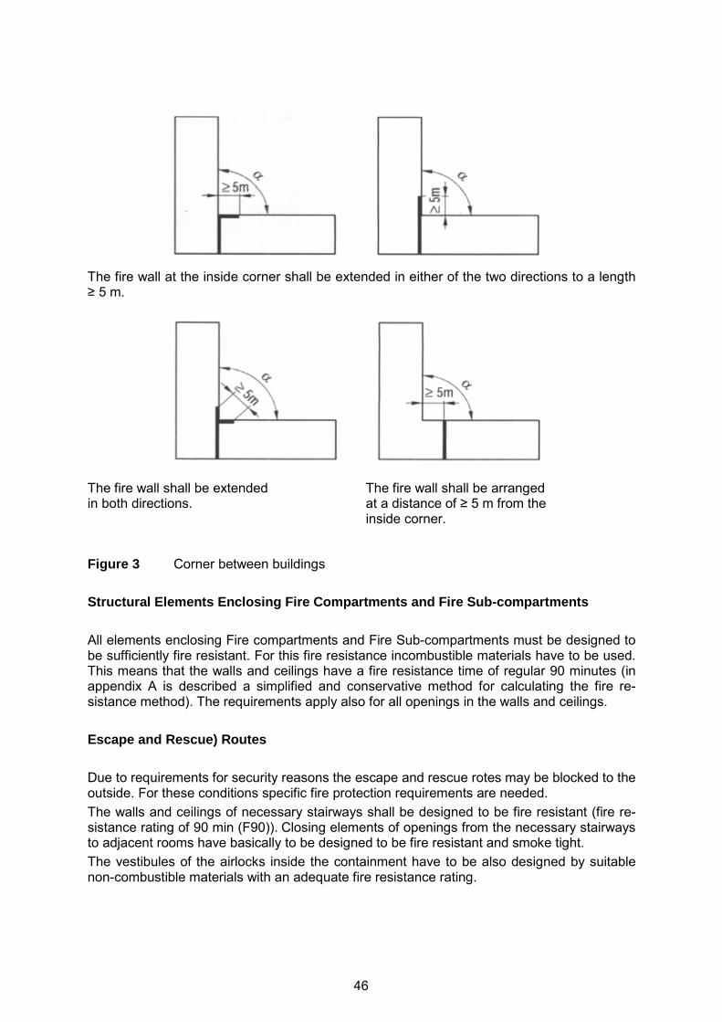
The fire wall at the inside corner shall be extended in either of the two directions to a length ≥ 5 m.
The fire wall shall be extended in both directions.
The fire wall shall be arranged at a distance of ≥ 5 m from the inside corner.
Figure 3 Corner between buildings Structural Elements Enclosing Fire Compartments and Fire Sub-compartments All elements enclosing Fire compartments and Fire Sub-compartments must be designed to be sufficiently fire resistant. For this fire resistance incombustible materials have to be used. This means that the walls and ceilings have a fire resistance time of regular 90 minutes (in appendix A is described a simplified and conservative method for calculating the fire re-sistance method). The requirements apply also for all openings in the walls and ceilings. Escape and Rescue) Routes Due to requirements for security reasons the escape and rescue rotes may be blocked to the outside. For these conditions specific fire protection requirements are needed. The walls and ceilings of necessary stairways shall be designed to be fire resistant (fire re-sistance rating of 90 min (F90)). Closing elements of openings from the necessary stairways to adjacent rooms have basically to be designed to be fire resistant and smoke tight. The vestibules of the airlocks inside the containment have to be also designed by suitable non-combustible materials with an adequate fire resistance rating.
46
Ventilat ion Systems, Equipment for Heat and Smoke Removal In the case that fire dampers are installed in the ventilation systems which have to be leak tight, these fire dampers shall inadmissibly impair the leak tightness of the systems. Pipes, adapter fittings, ducts and channels of ventilation conduits in a specified fire re-sistance class shall basically be designed of non-combustible materials. Exceptions are permissible, provided, the purpose is to remove corrosive gasses [11]). Appendix A: Simplified Validation Procedure for Determining the Required Fire Resistance Rating of Structure-related Fire Protection Measures The informative Appendix A provides a state-of-the-art approach for a validated determina-tion of the fire resistance rating of fire walls and other structural elements needed to ensure nuclear safety. This approach has based on a study “Examining the possibilities for estab-lishing standards regarding the verification of fire protection measures within the frame of KTA 2101.2 (Final Report)” by Hosser et al. [12]. The simplified validation procedure de-scribed may be used in determining the fire resistance rating of structure-related fire protec-tion measures. Some of the parameters in this approach were no longer state-of-the-art, making an update providing precision necessary. Moreover, the applicability of the proce-dure was further limited because of uncertainties needing further research. KTA 2101.3: FIRE PROTECTION IN NUCLEAR POWER PLANTS – FIRE PROTECTION OF MECHNICAL AND ELECTRICAL PLANT COMPONENTS This part of the German nuclear fire protection standard KTA 2101.3 supplements the safety standards KTA2101.1 Basic Requirements and KTA2101.2 Fire Protection of Structural Plant Components by additional requirements that apply specifically to the fire protection of mechanical and electrical plant components in nuclear power plants. Thus these 3 standards are closely connected and complement each other. The recent update of KTA 2101.3 (2014-11) [9] follows the demand of modifications pre-pared by the KTA (General Assembly), in particular for: − adapting references and definitions to up-to-date standards and codes, − updating and enhancing the requirements in order to make them consistent to up-to-date
national as well as international standards and codes, − updating in particular the technical requirements for extinguishing systems according to
the state-of-the-art, − reviewing the requirements for heat and smoke removal systems, in particular with re-
spect to access and escape routes, − including precise technical requirements for storage of pressurized gas cylinders, and − harmonizing this part of the standard KTA 2101 with the other two parts, KTA 2101.1
and KTA 2101.2. Moreover, the following general adaptations have been considered: − Moving more general requirements from KTA 2101.3 to KTA 2101.1 or KTA 2101.2 or
more technical requirements from KTA 2101.1 to KTA 2101.3 as far as suitable and avoiding duplications,
− Enhancing and harmonizing the wording of performance based requirements between the three parts of KTA 2101 and considering other fire protection standards and codes,
− Deleting definitions as well as requirements from this standard, if already well-established and regulated in the non-nuclear fire related building codes and standards.
47

The structure of the contents in the part 3 of the standard KTA 2101 has been slightly adapted accordingly resulting in the following main paragraphs: Fundamentals 1. Scope 2. Definitions 3. Fire Protection Measures for Mechanical Components and Systems 4. Fire Protection Measures for Electrical Facilities and Arrangements 5. Facilities for Fire Detection and Fire Alarm 6. Facilities for Fire Suppression 7. Ventilation Systems, Facilities for Smoke and Heat removal Examples for Adaptation: Fire Detection and Alarm Systems The former version of KTA 2101.3 included the requirement that “…as far as the fire detec-tion and alarm systems must be designed against earthquakes, safety standard KTA 2201.4 shall be applied. It is permissible to alternatively assume that the fire detection and alarm fa-cility stays available after an earthquake, provided, it is proven that the support structure of the fire alarm board retains it stability during earthquakes and it is ensured that any failed components in the fire alarm control centre and the corresponding local control centres can, if required, be replaced (e.g., by exchanging the modules) or repaired at short notice.” In the actual version of KTA 2101.3, a recommendation and a requirement for design are be-ing distinguished. It is recommended that the fire detection and alarm systems should be de-signed against earthquakes according to KTA 2201.4, if they are located in building areas which need to be seismically designed according to their safety relevance and if the seismic intensity I exceeds I = VI (EMS-98). The requirement is that the fire detection and alarm sys-tems shall be designed against event combinations of fires and other anticipated events if their function after an event combination has to be ensured according to KTA2101.1, par. 3.3. Seismically designed fire detection and alarm systems are available and represent state-of-the-art systems. Fire Extinguishing Systems: The former table “7.1-1 Suitability of stationary fire extinguishing systems in fire extinguish-ing areas typical for nuclear power plants” has been deleted as a result from the availability of various new fire extinguishing systems with gas, water, foam or combinations of extin-guishing agents as extinguishing media being available. The suitability of these systems has to be demonstrated for the special application and the design may follow the generally valid codes and standards. CONCLUSIONS Nuclear power plants in Germany are mainly designed and licensed according to the existing non-nuclear as well as nuclear fire safety standards, in general on the basis of deterministic requirements. The recently issued state-of-the-art high level “Safety Requirements to Nuclear Power Plants” also underline the need for an adequate fire protection design and the demonstration
48
of the reliability of the selected equipment by deterministic and probabilistic safety assess-ments. Although only nine nuclear power plant units are still in operation in Germany, fire protection remains a significant issue. The main reasons are the significance of fires even in shutdown states as well as during decommissioning and the long duration of post-commercial safe shutdown plant operational phase in several plant units phase in several plant units with the spent fuel elements remaining either in the containment or in the spent fuel pool for years requiring appropriate and reliable fire protection means being in place. The recently updated and enhanced KTA fire protection standards KTA 2101, Part 1 to 3 consider the specific German situation as well as lessons learned from various investigations of the post-Fukushima activities. They represent state-of-the-art requirements on a detailed level providing guidance to the user how to implement high level claims in the practical ap-plication. Moreover, together with other German nuclear standards, e.g. regarding internal explosions or seismic hazards, they provide a consistent approach for a safe design of nu-clear power plants for the entire plant operational lifetime. REFERENCES [1] Federal Ministry for the Environment, Nature Conservation, Building and Nuclear Safe-
ty, Safety Requirements for Nuclear Power Plants as amended and published on No-vember 22, 2012 and revised version of March 3, 2015, http://www.bfs.de/SharedDocs/Downloads/BfS/EN/hns/a1-english/A1-03-15-SiAnf.pdf.
[2] Röwekamp, M., et al.: “Ongoing Enhancements in the German Nuclear Regulatory Framework with Respect to Fire Safety”, in: Röwekamp, M., H.-P. Berg (Eds.): Proceedings of SMiRT 22, 13th International Seminar on Fire Safety in Nuclear Power Plants and Installations, September 18-20, 2013, Columbia, SC, USA, GRS-A-3731, Gesellschaft für Anlagen- und Reaktorsicherheit (GRS) mbH, Köln, Germany, Decem-ber 2013, http://www.grs.de/sites/default/files/pdf/grs-a-3731.pdf.
[3] Nuclear Safety Standards Commission (KTA, German for: Kerntechnischer Ausschuss), KTA 2101.1 (12/2000), “Fire Protection in Nuclear Power Plants, Part 1: Basic Re-quirements (Brandschutz in Kernkraftwerken Teil 1: Grundsätze des Brandschutzes)”, Safety Standards of the Nuclear Safety Standards Commission (KTA), December 2000, http://www.kta-gs.de/e/standards/2100/2101_1_engl_2000_12.pdf.
[4] Nuclear Safety Standards Commission (KTA, German for: Kerntechnischer Ausschuss), KTA 2101.2 (12/2000), “Fire Protection in Nuclear Power Plants, Part 2: Fire Protection of Structural Plant Components (Brandschutz in Kernkraftwerken Teil 2: Brandschutz an baulichen Anlagen)”, Safety Standards of the Nuclear Safety Standards Commission (KTA), December 2000, http://www.kta-gs.de/e/standards/2100/2101_2_engl_2000_12.pdf.
[5] Nuclear Safety Standards Commission (KTA, German for: Kerntechnischer Ausschuss), KTA 2101.3 (12/2000), “Fire Protection in Nuclear Power Plants, Part 3: Fire Protection of Mechanical and Electrical Components (Brandschutz in Kernkraftwerken Teil 3: Brandschutz an maschinen- und elektrotechnischen Anlagen)”, Safety Standards of the Nuclear Safety Standards Commission (KTA), December 2000, http://www.kta-gs.de/e/standards/2100/2101_3_engl_2000_12.pdf.
[6] Nuclear Safety Standards Commission (KTA, German for: Kerntechnischer Ausschuss), KTA 2103 (12/2000), “Explosion Protection in Nuclear Power Plants with Light Water Reactors (General and Case-specific Requirements), (Explosionsschutz in Kernkraft-werken mit Leichtwasserreaktoren (allgemeine und fallbezogene Anforderungen))”, Safety Standards of the Nuclear Safety Standards Commission (KTA), December 2000, http://www.kta-gs.de/e/standards/2100/2103_engl_2000_06.pdf.
49
[7] Nuclear Safety Standards Commission (KTA, German for: Kerntechnischer Ausschuss), KTA 2101.1 (2015-08), “Fire Protection in Nuclear Power Plants, Part 1: Basic Re-quirements (Brandschutz in Kernkraftwerken Teil 1: Grundsätze des Brandschutzes)”, Safety Standards of the Nuclear Safety Standards Commission (KTA), draft for approval by KTA General Assembly August 2015 (in German only).
[8] Nuclear Safety Standards Commission (KTA, German for: Kerntechnischer Ausschuss), KTA 2101.2 (2014-11), “Fire Protection in Nuclear Power Plants, Part 2: Fire Protection of Structural Plant Components (Brandschutz in Kernkraftwerken Teil 2: Brandschutz an baulichen Anlagen)”, Safety Standards of the Nuclear Safety Standards Commission (KTA), draft published for comments, November 2014 ( in German only), http://www.kta-gs.de/d/regeln/2100/2101_2_re_2014_11.pdf.
[9] Nuclear Safety Standards Commission (KTA, German for: Kerntechnischer Ausschuss), KTA 2101.3 (2014-11), “Fire Protection in Nuclear Power Plants, Part 3: Fire Protection of Mechanical and Electrical Components (Brandschutz in Kernkraftwerken Teil 3: Brandschutz an maschinen- und elektrotechnischen Anlagen)”, Safety Standards of the Nuclear Safety Standards Commission (KTA), draft published for comments, November 2014 (in German only), http://www.kta-gs.de/d/regeln/2100/2101_3_re_2014_11.pdf.
[10] Nuclear Safety Standards Commission (KTA, German for: Kerntechnischer Ausschuss), KTA 2103 (2015-07), “Explosion Protection in Nuclear Power Plants with Light Water Reactors (General and Case-specific Requirements), (Explosionsschutz in Kernkraft-werken mit Leichtwasserreaktoren (allgemeine und fallbezogene Anforderungen))”, Safety Standards of the Nuclear Safety Standards Commission (KTA), draft for approval by KTA General Assembly, August 2015 (in German only).
[11] Deutsches Institut für Normung (DIN) (Ed.),DIN 18232-5: Rauch- und Wärmefreihaltung - Teil 5: Maschinelle Rauchabzugsanlagen (MRA); Anforderungen, Bemessung, No-vember 2011(in German), http://www.din.de/cmd;jsessionid=JMVT9MO62GJUEFO9U6ACL1XM.1?languageid=de&workflowname=dinSearch.
[12] Hosser, D. et. al., Untersuchungen zur Regelfähigkeit von brandschutztechnischen Nachweisen im Rahmen von KTA 2101.2 (Abschlussbericht), (English: Examining the possibilities for establishing standards regarding the verification of fire protection mea-sures within the frame of KTA 2101.2 (Final Report), Schriftenreihe Reaktorsicherheit und Strahlenschutz, BMU-1996-467, im Auftrag des Bundesministeriums für Umwelt, Naturschutz und Reaktorsicherheit, February 1996, ISSN 0724-3316.
50
RECENT AMENDMENTS OF THE KTA 2101.2 FIRE BARRIER RESISTANCE RATING METHOD FOR GERMAN NPP AND
COMPARISON TO THE EUROCODE T-EQUIVALENT METHOD
Burkhard Forell
Gesellschaft für Anlagen- und Reaktorsicherheit (GRS) gGmbH, Cologne, Germany ABSTRACT The German nuclear standard KTA2101 on “Fire Protection in Nuclear Power Plants”, Part 2: “Fire Protection of Structural Plant Components” includes a simplified method for the fire resistance rating of fire barrier elements based on the t-equivalent approach. The method covers the specific features of compartments in nuclear power plant buildings in terms of the boundary conditions which have to be expected in the event of fire. The method has proven to be relatively simple and straightforward to apply. The paper gives an overview of amendments with respect to the rating method made within the regular review of the KTA 2101.2. A comparison to the method of the non-nuclear Eurocode 1 is also provided. The Eurocode method is closely connected to the German standard DIN 18230 on structural fire protection in industrial buildings. Special emphasis of the comparison is given to the ventilation factor, which has a large impact on the required fire resistance. INTRODUCTION A simplified t-equivalent rating method for the structural fire design of fire barriers and other structural elements in nuclear powers plants (NPP) has been developed by Hosser and Blume in the 1990ies [1], [2]. This method became part of the German nuclear fire safety standard KTA 2101, Part 2 on “Fire Protection of Structural Plant Components” [3] in 2000. Within the regular review of the fire safety standard series KTA 2101 the rating method has also been reviewed. The method was demonstrated and recommendations for amendments were given already in a paper presented on the preceding seminar [4]. In the following, the amendments of the simplified rating method already considered in the final draft of the amended update of KTA 2101.2 [5] and expected to be put into effect by end-2015 are provided in more detail. A comparison with the t-equivalent rating method of the Eurocode EN 1991-1-2, Informative Annex F “Equivalent time of fire exposure” [6] has also been carried out. Significant parts of the EN 1991-1-2 (EC 1) method are based on the German standard DIN 18230, Part 1 on “Structural fire protection in industrial buildings” [7], which provides a better documentation of the reference scenarios. All methods correlate the fire load density and other parameters with the equivalent time to the fire exposure according to the ISO 834 standard fire curve [8]. FIRE LOAD DENSITY The fire load density q [MJ/m2] is the heat of combustion of the fire loads i divided by the floor area of the compartment Af. In the KTA method, an effective fire load density qR [kWh/m2] is used considering two non-dimensional factors, namely the combustion efficiency
51
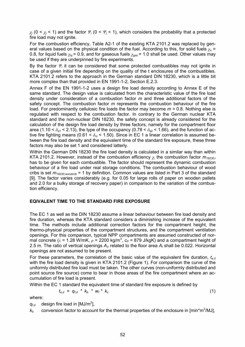
χj (0 < χj < 1) and the factor Ψi (0 < Ψj < 1), which considers the probability that a protected fire load may not ignite. For the combustion efficiency, Table A2-1 of the existing KTA 2101.2 was replaced by gen-eral values based on the physical condition of the fuel. According to this, for solid fuels χs = 0.8, for liquid fuels χlq = 0.9, and for gaseous fuels χgas = 1.0 shall be used. Other values may be used if they are underpinned by fire experiments. By the factor Ψi it can be considered that some protected combustibles may not ignite in case of a given initial fire depending on the quality of the t enclosures of the combustibles. KTA 2101.2 refers to the approach in the German standard DIN 18230, which is a little bit more complex than that provided in EN 1991-1-2, Section E.2.3. Annex F of the EN 1991-1-2 uses a design fire load density according to Annex E of the same standard. The design value is calculated from the characteristic value of the fire load density under consideration of a combustion factor m and three additional factors of the safety concept. The combustion factor m represents the combustion behaviour of the fire load. For predominantly cellulosic fire loads the factor may become m = 0.8. Nothing else is regulated with respect to the combustion factor. In contrary to the German nuclear KTA standard and the non-nuclear DIN 18230, the safety concept is already considered for the calculation of the design fire load density by three factors, namely for the compartment floor area (1.10 < δq1 < 2.13), the type of the occupancy (0.78 < δq2 < 1.66), and the function of ac-tive fire fighting means (0.61 < δni < 1.50). Since in EC 1 a linear correlation is assumed be-tween the fire load density and the equivalent time of the standard fire exposure, these three factors may also be set 1 and considered latterly. Within the German DIN 18230 the fire load density is calculated in a similar way than within KTA 2101.2. However, instead of the combustion efficiency χi the combustion factor m18230,i has to be given for each combustible. The factor should represent the dynamic combustion behaviour of a fire load under real storage conditions. The combustion behaviour of wood cribs is set m18230,woodcrib = 1 by definition. Common values are listed in Part 3 of the standard [9]. The factor varies considerably (e.g. for 0.05 for large rolls of paper on wooden pallets and 2.0 for a bulky storage of recovery paper) in comparison to the variation of the combus-tion efficiency. EQIVALENT TIME TO THE STANDARD FIRE EXPOSURE The EC 1 as well as the DIN 18230 assume a linear behaviour between fire load density and fire duration, whereas the KTA standard considers a diminishing increase of the equivalent time. The methods include additional correction factors for the compartment height, the thermo-physical properties of the compartment structures, and the compartment ventilation openings. For this comparison, typical NPP compartments are assumed constructed of nor-mal concrete (λ = 1.28 W/mK, ρ = 2200 kg/m3, cP = 879 J/kgK) and a compartment height of 2.5 m. The ratio of vertical openings AV related to the floor area Af shall be 0.022. Horizontal openings are not assumed to be present. For these parameters, the correlation of the basic value of the equivalent fire duration, te,0 with the fire load density is given in KTA 2101.2 (Figure 1). For comparison the curve of the uniformly distributed fire load must be taken. The other curves (non-uniformly distributed and point source fire source) come to bear in those areas of the fire compartment where an ac-cumulation of fire load is present. Within the EC 1 standard the equivalent time of standard fire exposure is defined by te,d = qf,d * kb * wf * kc (1) where: qf,d design fire load in [MJ/m2], kb conversion factor to account for the thermal properties of the enclosure in [min*m2/MJ],
52
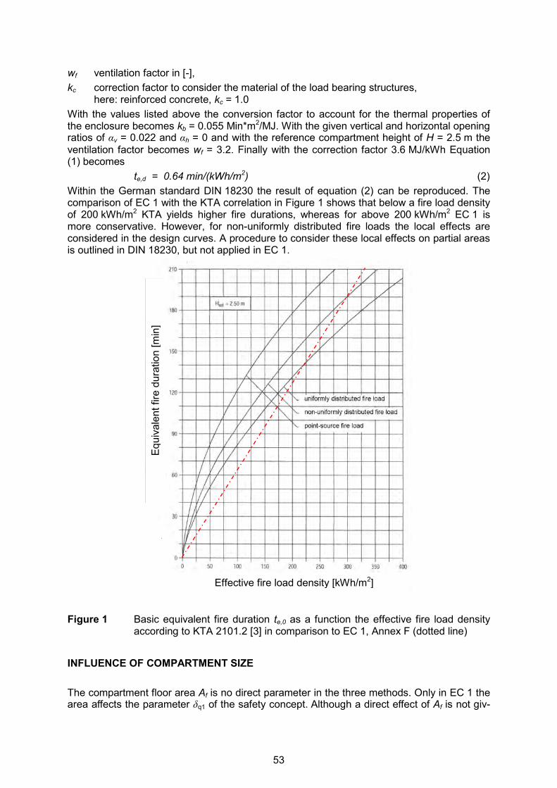
wf ventilation factor in [-], kc correction factor to consider the material of the load bearing structures, here: reinforced concrete, kc = 1.0 With the values listed above the conversion factor to account for the thermal properties of the enclosure becomes kb = 0.055 Min*m2/MJ. With the given vertical and horizontal opening ratios of αv = 0.022 and αh = 0 and with the reference compartment height of H = 2.5 m the ventilation factor becomes wf = 3.2. Finally with the correction factor 3.6 MJ/kWh Equation (1) becomes te,d = 0.64 min/(kWh/m2) (2) Within the German standard DIN 18230 the result of equation (2) can be reproduced. The comparison of EC 1 with the KTA correlation in Figure 1 shows that below a fire load density of 200 kWh/m2 KTA yields higher fire durations, whereas for above 200 kWh/m2 EC 1 is more conservative. However, for non-uniformly distributed fire loads the local effects are considered in the design curves. A procedure to consider these local effects on partial areas is outlined in DIN 18230, but not applied in EC 1.
Figure 1 Basic equivalent fire duration te,0 as a function the effective fire load density
according to KTA 2101.2 [3] in comparison to EC 1, Annex F (dotted line)
INFLUENCE OF COMPARTMENT SIZE The compartment floor area Af is no direct parameter in the three methods. Only in EC 1 the area affects the parameter δq1 of the safety concept. Although a direct effect of Af is not giv-
Effective fire load density [kWh/m2]
Equi
vale
nt fi
re d
urat
ion
[min
]
53

en, it should be noticed that the reference compartment floor area within the KTA is between Af = 150 m2 and Af = 450 m2 [1], whereas in DIN 18230 a reference compartment of Af = 2400 m2 was used [7]. EC 1 does provide no information regarding a reference compart-ment. The correction factor for the actual compartment height H in comparison to the reference compartment height Href is calculated by fH = (Href / H)0.3 (3) in all methodologies; however the reference height is Href = 2.5 m in KTA 2101.2 and 6.0 m in the other standards. VENTILATION EFFECTS General Ventilation has got a crucial influence on the equivalent time of fire exposure. The larger the air-inflow to the compartment, the more heat can be produced. For combustion of organic materials, the heat release per kilogram of air is ∆Hair ≈ 3.0 MJ/kg. For low air inflows, small heat release rates in the fire compartments are given that come along with large fire durations to consume all fuel (possibly unrealistic) or under-ventilated fires (not conservative). The ventilation factor will be small for low air inflows. For large air inflows the compartments will be over-ventilated and cooled by the excess air that leaves the compartment. Therefore the ventilation factor will be small for large air in-flows. The most severe ventilation (i.e. the maximum of the ventilation factor) has to be expected for stoichiometric conditions. However, defining the air inflow under stoichiometric conditions requires knowledge of the fuel mass loss rate, which is typically afflicted with large uncertain-ties. Therefore, the behaviour of the curve of the ventilation factor depends on the chosen design fire in relation to the reference compartment. The location of the opening ratio where stoichiometric conditions occur depends on the av-erage heat release rate per unit compartment area (HRRPUCA), which is supported by the fuels within the compartment. The air consumption per second and square-meter of floor ar-ea is �̇�air / Af = HRRPUCA / ∆Hair. If the air supply is by vertical ventilation areas, by recast-ing the Kawagoe equation the corresponding opening ratio can be calculated by Av / Af = HRRPUCA/∆Hair / (0.52 * h
0.5) (4) Ventilation of the KTA Reference Compartment The ventilation of a NPP compartment may consist of natural air flow through vertical open-ings and/or mechanical ventilation. To consider the contribution by mechanical ventilation by the frequently used opening ratio αv = Av / Af for the vertical ventilation area, an effective opening area was introduced by AV,eff = AV + �̇�zu / F [m2] (5) where: AV: overall surface area of vertical vents in the enclosing walls [m2], �̇�zu: volumetric air supply rate in the case of forced ventilation [m3/h], A: surface area of the compartment [m2], F: equivalence factor between mechanical and natural airflow, Fold = 6000 m3/h in KTA 2101.1 (as of 2000) [3],
54
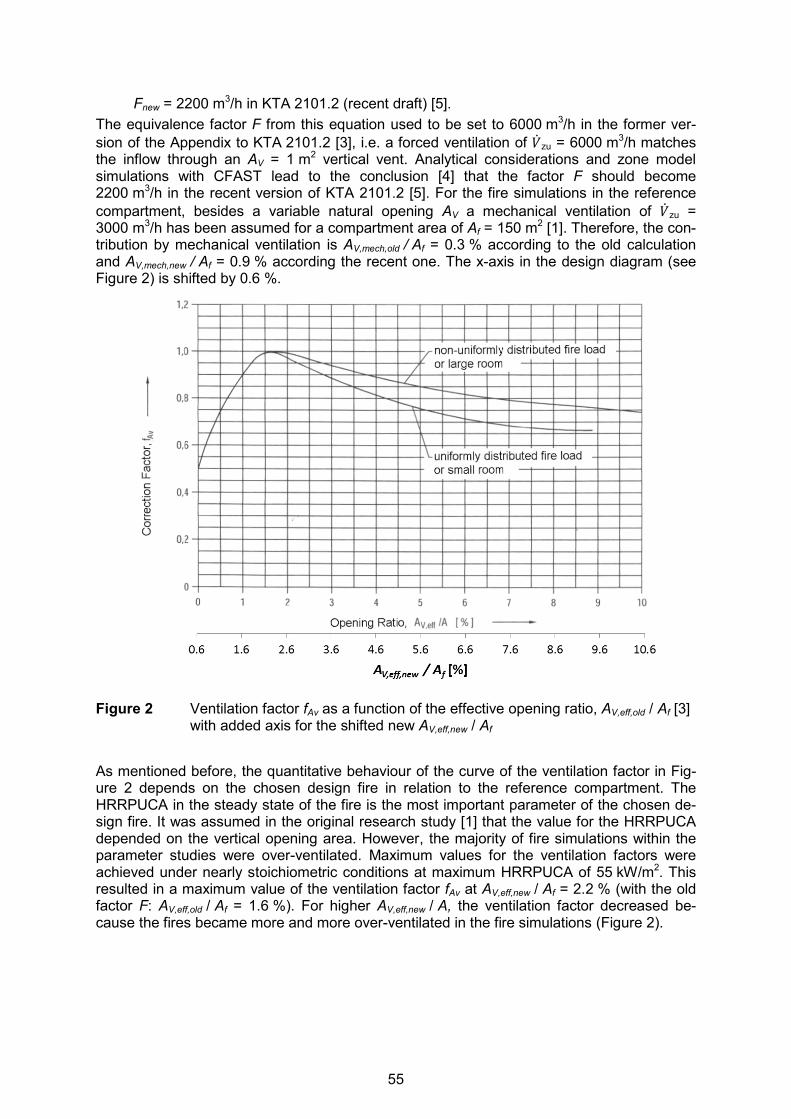
Fnew = 2200 m3/h in KTA 2101.2 (recent draft) [5]. The equivalence factor F from this equation used to be set to 6000 m3/h in the former ver-sion of the Appendix to KTA 2101.2 [3], i.e. a forced ventilation of �̇�zu = 6000 m3/h matches the inflow through an AV = 1 m2 vertical vent. Analytical considerations and zone model simulations with CFAST lead to the conclusion [4] that the factor F should become 2200 m3/h in the recent version of KTA 2101.2 [5]. For the fire simulations in the reference compartment, besides a variable natural opening AV a mechanical ventilation of �̇�zu = 3000 m3/h has been assumed for a compartment area of Af = 150 m2 [1]. Therefore, the con-tribution by mechanical ventilation is AV,mech,old / Af = 0.3 % according to the old calculation and AV,mech,new / Af = 0.9 % according the recent one. The x-axis in the design diagram (see Figure 2) is shifted by 0.6 %.
Figure 2 Ventilation factor fAv as a function of the effective opening ratio, AV,eff,old / Af [3]
with added axis for the shifted new AV,eff,new / Af
As mentioned before, the quantitative behaviour of the curve of the ventilation factor in Fig-ure 2 depends on the chosen design fire in relation to the reference compartment. The HRRPUCA in the steady state of the fire is the most important parameter of the chosen de-sign fire. It was assumed in the original research study [1] that the value for the HRRPUCA depended on the vertical opening area. However, the majority of fire simulations within the parameter studies were over-ventilated. Maximum values for the ventilation factors were achieved under nearly stoichiometric conditions at maximum HRRPUCA of 55 kW/m2. This resulted in a maximum value of the ventilation factor fAv at AV,eff,new / Af = 2.2 % (with the old factor F: AV,eff,old / Af = 1.6 %). For higher AV,eff,new / A, the ventilation factor decreased be-cause the fires became more and more over-ventilated in the fire simulations (Figure 2).
55
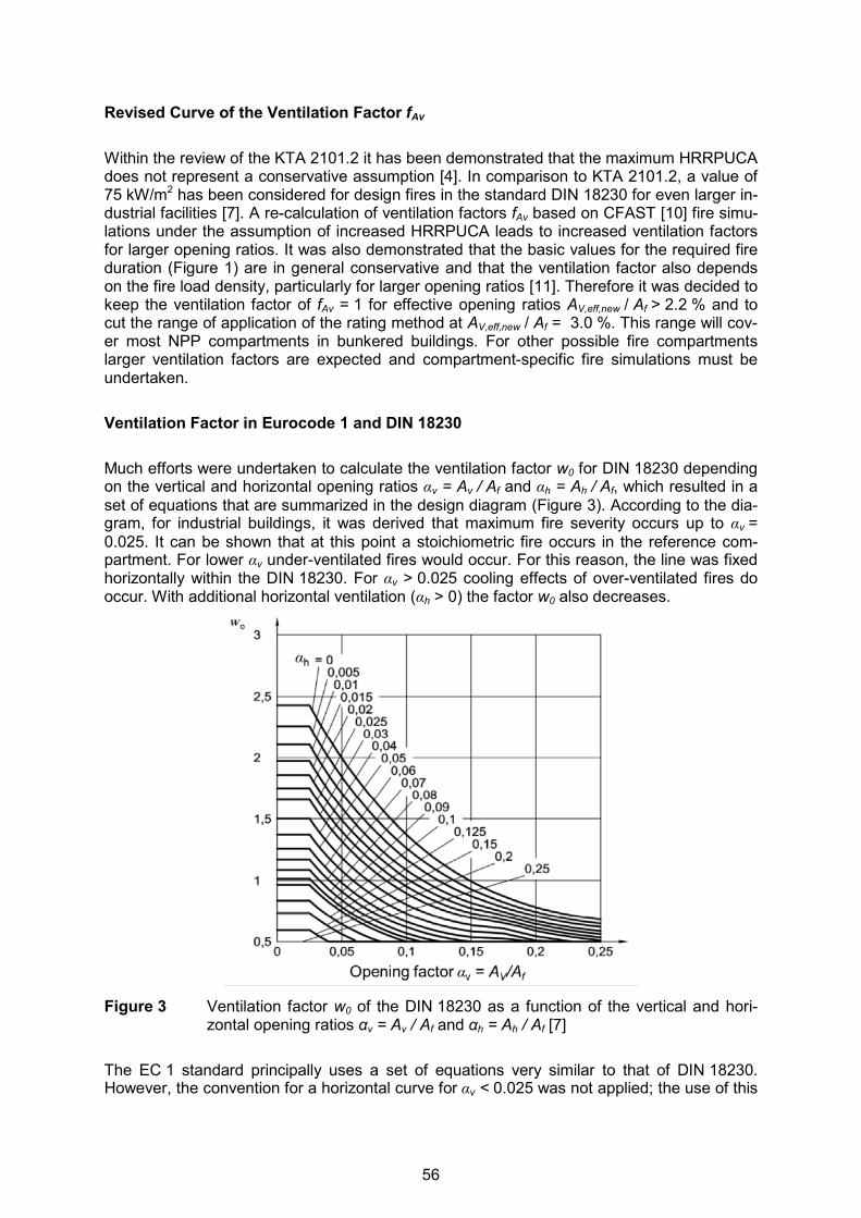
Revised Curve of the Ventilation Factor fAv Within the review of the KTA 2101.2 it has been demonstrated that the maximum HRRPUCA does not represent a conservative assumption [4]. In comparison to KTA 2101.2, a value of 75 kW/m2 has been considered for design fires in the standard DIN 18230 for even larger in-dustrial facilities [7]. A re-calculation of ventilation factors fAv based on CFAST [10] fire simu-lations under the assumption of increased HRRPUCA leads to increased ventilation factors for larger opening ratios. It was also demonstrated that the basic values for the required fire duration (Figure 1) are in general conservative and that the ventilation factor also depends on the fire load density, particularly for larger opening ratios [11]. Therefore it was decided to keep the ventilation factor of fAv = 1 for effective opening ratios AV,eff,new / Af > 2.2 % and to cut the range of application of the rating method at AV,eff,new / Af = 3.0 %. This range will cov-er most NPP compartments in bunkered buildings. For other possible fire compartments larger ventilation factors are expected and compartment-specific fire simulations must be undertaken. Ventilation Factor in Eurocode 1 and DIN 18230 Much efforts were undertaken to calculate the ventilation factor w0 for DIN 18230 depending on the vertical and horizontal opening ratios αv = Av / Af and αh = Ah / Af, which resulted in a set of equations that are summarized in the design diagram (Figure 3). According to the dia-gram, for industrial buildings, it was derived that maximum fire severity occurs up to αv = 0.025. It can be shown that at this point a stoichiometric fire occurs in the reference com-partment. For lower αv under-ventilated fires would occur. For this reason, the line was fixed horizontally within the DIN 18230. For αv > 0.025 cooling effects of over-ventilated fires do occur. With additional horizontal ventilation (αh > 0) the factor w0 also decreases.
Figure 3 Ventilation factor w0 of the DIN 18230 as a function of the vertical and hori-
zontal opening ratios αv = Av / Af and αh = Ah / Af [7] The EC 1 standard principally uses a set of equations very similar to that of DIN 18230. However, the convention for a horizontal curve for αv < 0.025 was not applied; the use of this
56
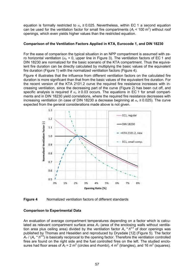
equation is formally restricted to αv ≥ 0.025. Nevertheless, within EC 1 a second equation can be used for the ventilation factor for small fire compartments (Af < 100 m2) without roof openings, which even yields higher values than the restricted equation. Comparison of the Ventilation Factors Applied in KTA, Eurocode 1, and DIN 18230 For the ease of comparison the typical situation in an NPP compartment is assumed with ze-ro horizontal ventilation (αh = 0, upper line in Figure 3). The ventilation factors of EC 1 and DIN 18230 are normalized for the basic scenario of the KTA compartment. Thus the equiva-lent fire duration can be directly calculated by multiplying the basic values of the equivalent fire duration (Figure 1) with the normalized ventilation factors (Figure 4). Figure 4 illustrates that the influence from different ventilation factors on the calculated fire duration is more significant than that from the basic values of the equivalent fire duration. For the recent version of the KTA 2101.2 curve the required fire resistance increases with in-creasing ventilation, since the decreasing part of the curve (Figure 2) has been cut off, and specific analysis is required if αv ≥ 0.03 occurs. The equations in EC 1 for small compart-ments and in DIN 18230 yield correlations, where the required fire resistance decreases with increasing ventilation (in case of DIN 18230 a decrease beginning at αv ≥ 0.025). The curve expected from the general considerations made above is not given.
Figure 4 Normalized ventilation factors of different standards
Comparison to Experimental Data An evaluation of average compartment temperatures depending on a factor which is calcu-lated as relevant compartment surface area AT (area of the enclosing walls without ventila-tion area plus ceiling area) divided by the ventilation factor Av * h0.5 of door openings was published by Thomas and Heselden and reproduced by Drysdale [12] (Figure 5). The factor AT / (Av * h0.5) is basically reciprocal to the opening factor. Therefore the ventilation controlled fires are found on the right side and the fuel controlled fires on the left. The studied enclo-sures had floor areas of Af = 2 m2 (circles and rhombi), 4 m2 (triangles), and 16 m2 (squares).
57

Solid points are means of 8 to 12 experiments. The stoichiometric fires with maximum tem-peratures occurred at about AT / (Av * h0.5) ≈ 12 m-0.5.
AT / (AV h0.5) [m-1/2]
Figure 5 Average compartment temperatures during the steady state burning for wood
crib fires in model enclosures as a function of a factor AT / (Av * h0.5) [12] The given data was re-evaluated and the opening ratio AV / Af was calculated together with a regression curve by a third order polynomial (Figure 6). Maximum temperatures in these model enclosures occurred at opening ratios of about AV / Af = 40 % - much larger than the assumed maximum for the ventilation factor in the non-nuclear standards (e.g. 2.5 % in the German standard DIN 18230). According to equation (4) an opening ratio of AV / Af = 40 % supports a maximum HRRPUCA of 880 kW/m2.
Figure 6 Average compartment temperatures during the steady state burning for wood crib fires in model enclosures as a function the opening ratio AV / Af
Nuclear power plant compartments are about one to two orders of magnitude larger in floor area than the studied model enclosures and industrial buildings are even larger two to four orders of magnitude. Therefore, the opening ratios where maximum fire severities are reached in real-scale compartments will shift to smaller ratios compared to Figure 6, be-
58

cause larger compartments will support a smaller average HRRPUCA than small compart-ments. For industrial buildings, the ratio of maximum fire severity will occur at smaller open-ing ratios than in compartments of a nuclear power plant. The rating method as provided within the Appendix of the recent version of KTA 2101.2 [3] can only be applied up to an (effective) opening ratio of Av / Af = 0.03, which allows for a HRRPUCA of 60 kW/m2. For comparison, in case of a cable room in a nuclear power plant with an assumed HRRPUCA of 100 kW/m2, given a door height of h = 2 m, the opening ratio which allows stoichiometric conditions is Av / Af = 0.045. If such a large effective opening ra-tio would be given in a nuclear power plant compartment, the rating method cannot be ap-plied and special considerations, e.g. by specific fire simulations, are needed. Natural and Forced Ventilation under Conditions of Typical NPP Compartments Taking into account the real conditions of compartment fires in NPP, there are additional in-fluences from natural and forced ventilation to be considered:
− The oxygen supply by natural ventilation through doors that do not open to atmosphere but to adjacent compartments is much smaller than assumed by the Kawagoe equation. This is first because the pressure difference over a door to open atmosphere is larger than over a door to an adjacent compartment. Moreover, the atmosphere circulates be-tween the two compartments and therefore the oxygen content is depleted.
− Forced ventilation of compartments is typically carried out by a combined push and pull system. Due to the compartment gas temperature, the smoke gas expands and the mass flows according to design will be reduced. The extent of this effect depends on the actual pressure-flow-characteristics of the HVAC system.
As natural and forced ventilation are principally overestimated with regard to real fire condi-tions in NPP compartments, the design with the nominal values is conservative as long as the ventilation factor fAv is monotonically increasing with the opening ratio AV,eff / A. This is achieved by the recent draft version of the German nuclear standard KTA 2101.2 [5]. CONCLUSIONS A mayor uncertainty for structural design methods in fire safety engineering results from the source term for the heat release rate. For ventilation controlled fires, at least the maximum HRR in a compartment is known, which allows a conservative design. For fuel controlled fires, the uncertainty with respect to the resulting ventilation factor is larger. Therefore, open-ing ratios leading to large uncertainties are no longer covered by the design method provid-ed in the Appendix of the German nuclear standard KTA 2101.2 and need special considera-tion. However, the bunkered buildings of NPP will in most cases provide compartments with boundary conditions that allow a simple and conservative design of structural elements ac-cording to the amended KTA method. REFERENCES [1] Hosser, D., et al., Untersuchungen zur Regelfähigkeit von brandschutztechnischen
Nachweisen im Rahmen von KTA 2101.2. Schriftenreihe Reaktorsicherheit und Strah-lenschutz, BMU-1996-467, ISSN 0724-3316, 1996 (in German).
[2] Blume, G., D. Hosser, “Simplified Method for Risk oriented Design of Structural Fire Protection Measures”, in: OECD Nuclear Energy Agency Committee on the Safety of Nuclear Installations Proceedings from International Workshop on Fire Risk Assess-
59

ment, Helsinki, Finland, 29 June – 1 July 1999, NEA/CSNI/R(99)26, Paris, France, June 2000, http://www.oecd-nea.org/nsd/docs/1999/csni-r99-26.pdf.
[3] Nuclear Safety Standards Commission (KTA, German for: Kerntechnischer Ausschuss), KTA 2101.2 (12/2000), “Fire Protection in Nuclear Power Plants, Part 2: Fire Protection of Structural Plant Components (Brandschutz in Kernkraftwerken Teil 2: Brandschutz an baulichen Anlagen)”, Safety Standards of the Nuclear Safety Standards Commission (KTA), December 2000, http://www.kta-gs.de/e/standards/2100/2101_2_engl_2000_12.pdf.
[4] Forell, B., Recent Considerations on the Fire Barrier Resistance Rating for German Nu-clear Power Plants, in: Proceedings of SMiRT 22, 13th International Seminar on Fire Safety in Nuclear Power Plants and Installations, September 18-20, 2013, Columbia, SC, USA, GRS-A-3731, Gesellschaft für Anlagen- und Reaktorsicherheit (GRS) mbH, Köln, Germany, December 2013, http://www.grs.de/publikation/grs-A-3731.
[5] Nuclear Safety Standards Commission (KTA, German for: Kerntechnischer Ausschuss), KTA 2101.2 (2015-08), “Fire Protection in Nuclear Power Plants, Part 2: Fire Protection of Structural Plant Components (Brandschutz in Kernkraftwerken Teil 2: Brandschutz an baulichen Anlagen)”, Safety Standards of the Nuclear Safety Standards Commission (KTA), draft for KTA approval, August 2015 (in German).
[6] Eurocode EN 1991-1-2: Eurocode 1: Actions on structures - Part 1-2: General actions - Actions on structures exposed to fire, 2002 + AC: 2009.
[7] Deutsches Institut für Normung (DIN) (Ed.), DIN 18230-1: Structural fire protection in in-dustrial buildings – Part 1: Analytically required fire resistance time, September 2010 (in German.
[8] International Organization of Standardization (ISO) (Ed.), ISO 834-1: Fire-resistance tests - Elements of building construction - Part 1: General requirements, Geneva, Swit-zerland, 1999, http://www.iso.org/iso/home/store/catalogue_tc/catalogue_detail.htm?csnumber=2576.
[9] Deutsches Institut für Normung (DIN) (Ed.), DIN 18230-3: Structural fire protection in in-dustrial buildings – Part 3: Values for calculation August 2002 (in German).
[10] Peacock, R. D., et al., CFAST - Consolidated Model of Fire Growth and Smoke Transport (Version 6), User`s Guide, NIST Special Publication 1041, National Institute of Standards and Technology (NIST), Gaithersburg, MD, USA, August 2005.
[11] Forell, B., Neufestlegung des Faktors fAv zur Berücksichtigung von Ventilationseinflüs-sen im vereinfachten Nachweisverfahren nach Anhang A der KTA 2101.2 (12/2000) und Anwendungsbeispiele, Technical Note, Gesellschaft für Anlagen und Reaktorsi-cherheit (GRS) gGmbH, Cologne, Germany, May 2015 (in German).
[12] Drysdale, D., An Introduction to Fire Dynamics, 2nd Edition, Wiley & Sons, Chichester. 1998.
60

23rdInternational Conference on Structural Mechanics in Reactor Technology (SMiRT 23) - 14h
International Post-Conference Seminar on “FIRE SAFETY IN NUCLEAR POWER PLANTS AND INSTALLATIONS“
ENHANCEMENTS IN PSA REGULATION AND GUIDANCE ON FIRE RISK ANALYSIS FOR NUCLEAR POWER PLANTS
Heinz-Peter Berg1
1 Bundesamt für Strahlenschutz (BfS), Willy-Brandt-Str. 5, 38226 Salzgitter, Germany
ABSTRACT Fire PSA (probabilistic safety analysis) is required as part of the probabilistic safety assess-ment within Periodic Safety Reviews (PSR) in Germany. Fire PSAs have been conducted for all nuclear power plants in Germany within the second PSR. Thus, Fire PSA has become an additional tool to supplement deterministic assessment of the fire protection for supporting decision making, but has been focused on full power plant operational states. However, according to the German PSA Guideline and its corresponding technical docu-ments on PSA methods and data issued 2005, the scope was extended to low power and shutdown states, however not assessing internal and external hazards for these states. The most recent activities with regard to PSA as supplementary tool for safety assessment focus on improvements with respect to low power and shutdown (LPSD), considering fuel damage states, and in addition covering internal hazards, in particular fire. For each phase during LPSD those compartments or plant areas have to be identified where fire events may inadmissibly impair items important to safety. The extension of Fire PSA to LPSD states has to be particularly applied to those plants, for which a third PSR is required by the German regulation. In addition, the safety significance of those plant modifications important to safety should be evaluated, for which a significant effect on the PSA results can be expected. This also covers the safety demonstration that the fire safety means needed to meet the nuclear protection goals are adequate. INTRODUCTION Operating nuclear power plants in Germany have been designed and constructed in different plant generations resulting in differences in the design and layout of fire protection features. Thus, it was necessary to assess the currently realized fire safety status of the nuclear pow-er plant and its suitability. In the past, the safety concept of nuclear power plants as well as licensing decisions by the competent regulatory authorities in charge and their experts in Germany were mainly based on deterministic principles such as prevention or control of abnormal plant operational condi-tions and incidents by technical means to ensure high reliability. In the meantime, probabilis-tic safety analyses (PSA) have come into effect as analytical tools. They are mainly applied in the frame of Periodic Safety Reviews and shall supplement deterministic safety demon-strations in order to verify the balance of the plant design related to safety. However, in general the regulatory framework for nuclear power plants in Germany is still a deterministic one comprising comprehensive and partly very detailed regulatory documents, guidelines and recommendations of the regulatory body and advisory bodies, but also nu-clear safety standards and codes incorporated in a corresponding pyramid type legal struc-ture as shown in Figure 1.
61
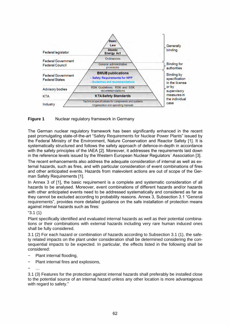
Figure 1 Nuclear regulatory framework in Germany The German nuclear regulatory framework has been significantly enhanced in the recent past promulgating state-of-the-art “Safety Requirements for Nuclear Power Plants” issued by the Federal Ministry of the Environment, Nature Conservation and Reactor Safety [1]. It is systematically structured and follows the safety approach of defence-in-depth in accordance with the safety principles of the IAEA [2]. Moreover, it addresses the requirements laid down in the reference levels issued by the Western European Nuclear Regulators´ Association [3]. The recent enhancements also address the adequate consideration of internal as well as ex-ternal hazards, such as fires, and with particular consideration of event combinations of fires and other anticipated events. Hazards from malevolent actions are out of scope of the Ger-man Safety Requirements [1]. In Annex 3 of [1], the basic requirement is a complete and systematic consideration of all hazards to be analysed. Moreover, event combinations of different hazards and/or hazards with other anticipated events need to be addressed systematically and considered as far as they cannot be excluded according to probability reasons. Annex 3, Subsection 3.1 “General requirements”, provides more detailed guidance on the safe installation of protection means against internal hazards such as fires: “3.1 (1) Plant specifically identified and evaluated internal hazards as well as their potential combina-tions or their combinations with external hazards including very rare human induced ones shall be fully considered. 3.1 (2) For each hazard or combination of hazards according to Subsection 3.1 (1), the safe-ty related impacts on the plant under consideration shall be determined considering the con-sequential impacts to be expected. In particular, the effects listed in the following shall be considered:
− Plant internal flooding,
− Plant internal fires and explosions,
− … 3.1 (3) Features for the protection against internal hazards shall preferably be installed close to the potential source of an internal hazard unless any other location is more advantageous with regard to safety.”
62
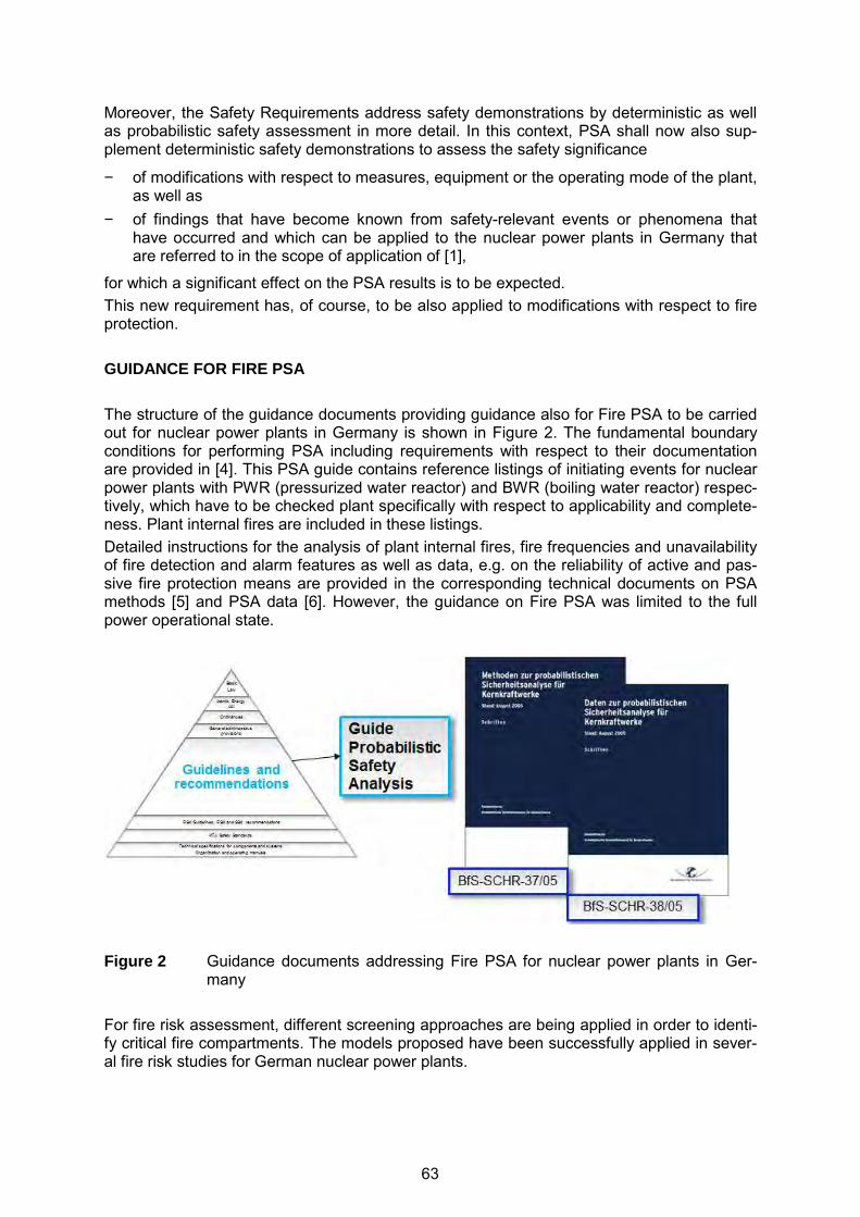
Moreover, the Safety Requirements address safety demonstrations by deterministic as well as probabilistic safety assessment in more detail. In this context, PSA shall now also sup-plement deterministic safety demonstrations to assess the safety significance
− of modifications with respect to measures, equipment or the operating mode of the plant, as well as
− of findings that have become known from safety-relevant events or phenomena that have occurred and which can be applied to the nuclear power plants in Germany that are referred to in the scope of application of [1],
for which a significant effect on the PSA results is to be expected. This new requirement has, of course, to be also applied to modifications with respect to fire protection. GUIDANCE FOR FIRE PSA The structure of the guidance documents providing guidance also for Fire PSA to be carried out for nuclear power plants in Germany is shown in Figure 2. The fundamental boundary conditions for performing PSA including requirements with respect to their documentation are provided in [4]. This PSA guide contains reference listings of initiating events for nuclear power plants with PWR (pressurized water reactor) and BWR (boiling water reactor) respec-tively, which have to be checked plant specifically with respect to applicability and complete-ness. Plant internal fires are included in these listings. Detailed instructions for the analysis of plant internal fires, fire frequencies and unavailability of fire detection and alarm features as well as data, e.g. on the reliability of active and pas-sive fire protection means are provided in the corresponding technical documents on PSA methods [5] and PSA data [6]. However, the guidance on Fire PSA was limited to the full power operational state.
Figure 2 Guidance documents addressing Fire PSA for nuclear power plants in Ger-
many For fire risk assessment, different screening approaches are being applied in order to identi-fy critical fire compartments. The models proposed have been successfully applied in sever-al fire risk studies for German nuclear power plants.
63

For the detailed quantitative fire risk analysis, a standard event tree has been developed with nodes for fire initiation, ventilation of the room, fire detection and suppression, both for the incipient fire phase as well as for fully developed fires, and a node for fire propagation. This standard event tree has to be adapted to each critical fire compartment, revealing the frequency and nature of fire induced initiating events, the list of equipment damaged, binned corresponding to different damage states, and damage frequencies. If a complete plant specific, at least Level 1 PSA is available, the fire induced hazard states frequencies will be summarized for all initiating events and specified as input to the corre-sponding event tree of the Level 1 PSA. Furthermore, the plant hazard states have to be included and adopted into the fault trees. The plant hazard state frequencies are estimated for each transient as the sum of the indi-vidual event core damage frequencies. The total plant hazard state frequency is obtained by summarizing the contributions of all transients. Moreover, the fire induced core damage fre-quency has to be calculated for the full power operational state. The “Safety Requirements to Nuclear Power Plants” in [1] further demand that state-of-the-art methods, models and data have to be applied in the frame of PSA. As far as possible plant specific data have to be applied. If no suitable plant specific data are available from the operating experience, generic data may be used if justified [6]. In the meantime, guidance for performing fire PSA for low power and shutdown (LPSD) plant operational states (POS) – including the post-commercial safe shutdown state – has been developed and provided in detail in [7] and is outlined below. For each phase during low power and shutdown those compartments or plant areas have to be identified, where fire events may inadmissibly impair items important to safety. In particu-lar, the following changes and enhancements with respect to the input data have to be con-sidered: − The total compartment inventory of SSC including cables has to be associated to the
POS in accordance with their safety functions to one of the following three classes (1 – no safety relevance, 2 – basic event in the PSA plant model, 3 – failure may contribute to an initiating event).
− Depending on the POS, changes of the status with regard to fire protection in given compartments are possible (e.g., BWR containment no longer filled with inert gas). These changes as well as well as those with respect to fire barriers, amount and distri-bution of fire loads, effects of maintenance and repair work, changes in the number of humans present and the duration of their presence in given fire compartments have to be considered for Fire PSA.
− In case of a fire induced loss of the entire compartment inventory, the list of potential ini-tiating events should be adapted and, if necessary, further completed depending on the respective POS.
− For those compartments and/or plant areas identified to be significant within the screen-ing, detailed analyses have to be carried out covering the following three analytical steps:
• Fire occurrence frequency estimation: For that purpose, the methods in place for full power operational states can be ap-plied, taking into account the changes in fire safety according to the conditions dur-ing LPSD.
• Fire damage frequency calculation: The methods for full power operation (fire specific event tree analysis) can be ap-plied.
• Fuel damage frequency estimation: For this calculation, the event tree analysis of the respective initiating event from
64
LPSD PSA can be used. It has to be checked, if those human actions needed for the control of initiating events still can be performed in case of fire.
The guidance for LPSD plant operational states will be part of an additional supplementary document to [5] and [6] which is intended to be issued by the end of 2015 [7]. In the context of modelling plant specific fire event and fault trees, reliability data with regard to fire protections means are required. In [6], technical reliability data for various active fire protection features have been provided resulting from plant specific analyses of the operat-ing experience from different nuclear power plants. In order to update the already existing reliability data for fire protection features, in particular, failure rates per hours of plant operation, as well as to extend the database covering addi-tional plant units the operating experience from inspections of the following components and systems installed in six nuclear power plant units has been further analysed:
− Fire detection systems with the corresponding main fire alarm panels, subsidiary fire alarm boards, detection drawers, detection lines/groups as well as automatic and manu-al fire detectors,
− Fire dampers and smoke extraction dampers in ventilation ducts with different actuation mechanisms (thermally by fusible link or remote controlled by typically electro-mechanical or pneumatic actuation),
− Fire doors between rooms, partly equipped with electrically hold-open devices, and − Stationary fire extinguishing systems and equipment including the corresponding extin-
guishing media supplies, fire water pumps, hydrants, etc.
The investigations have been carried out by analysing the documentation of periodic in-service inspections as well as additional information and reports which resulted from the in-spection findings. In case of more complex systems such as the fire detection systems, fault trees are presented for estimating the system’s reliability in addition to the components’ reli-ability data. These data are then used in a second step to provide generic data, based only on the opera-tional experience from nuclear power plants in Germany. The updated and extended generic database covers 111 plant operational years of in total six German nuclear power plants units of different type (PWR as well as BWR) and age. This new set of reliability data for fire protections means will be part of the supplementary document [7]. More details regarding the derivation of the new data set are provided in [8] and [9]. These data may also be applied as a-priori information for estimating the reliability of com-ponents of a similar design and an equivalent inspection and maintenance practice in the frame of Fire PSA for nuclear power plants in other countries. As already explained in the first section of this paper, PSA shall also supplement determinis-tic safety demonstrations to assess the safety significance of modifications of measures, equipment or the operating mode of the plant, as well as of findings that have become known from events relevant to nuclear safety or phenomena that have occurred and which can be applied to the nuclear power plants in Germany that are referred to in the scope of application of [1], for which a significant effect on the results of PSA can be expected. Such modifications of measures, equipment or the operating mode of the plant must neither lead to an increase in the average core damage frequency (CDF) nor in the average fre-quency of large and early releases (LRF/LERF) if compared to the unchanged conditions of the plant. This is valid for all plant operational states, power operation as well as the entire low power and shutdown states, considering all plant internal events as well as all internal and external hazards including the very rare human induced external ones. Hence, the new German Safety Requirements [1] contain an implicit definition of quantitative safety criteria: Mean CDF and LERF of full scope Level 1 and Level 2 PSA, respectively,
65
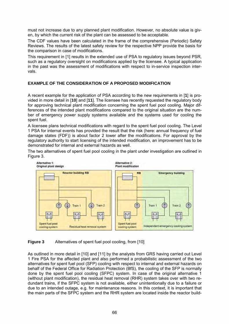
must not increase due to any planned plant modification. However, no absolute value is giv-en, by which the current risk of the plant can be assessed to be acceptable. The CDF values have been calculated in the frame of the comprehensive (Periodic) Safety Reviews. The results of the latest safety review for the respective NPP provide the basis for the comparison in case of modifications. This requirement in [1] results in the extended use of PSA to regulatory issues beyond PSR, such as a regulatory oversight on modifications applied by the licensee. A typical application in the past was the assessment of modifications with respect to in-service inspection inter-vals. EXAMPLE OF THE CONSIDERATION OF A PROPOSED MODIFICATION A recent example for the application of PSA according to the new requirements in [1] is pro-vided in more detail in [10] and [11]. The licensee has recently requested the regulatory body for approving technical plant modification concerning the spent fuel pool cooling. Major dif-ferences of the intended plant modifications compared to the original situation are the num-ber of emergency power supply systems available and the systems used for cooling the spent fuel. A licensee plans technical modifications with regard to the spent fuel pool cooling. The Level 1 PSA for internal events has provided the result that the risk (here: annual frequency of fuel damage states (FDF)) is about factor 2 lower after the modifications. For approval by the regulatory authority to start licensing of the intended modification, an improvement has to be demonstrated for internal and external hazards as well. The two alternatives of spent fuel pool cooling in the plant under investigation are outlined in Figure 3.
Figure 3 Alternatives of spent fuel pool cooling, from [10] As outlined in more detail in [10] and [11] by the analysts from GRS having carried out Level 1 Fire PSA for the affected plant and also performed a probabilistic assessment of the two alternatives for spent fuel pool (SFP) cooling with respect to internal and external hazards on behalf of the Federal Office for Radiation Protection (BfS), the cooling of the SFP is normally done by the spent fuel pool cooling (SFPC) system. In case of the original alternative 1 (without plant modification), the residual heat removal (RHR) system takes over with two re-dundant trains, if the SFPC system is not available, either unintentionally due to a failure or due to an intended outage, e.g. for maintenance reasons. In this context, it is important that the main parts of the SFPC system and the RHR system are located inside the reactor build-
66
ing. In case of the alternative 2 (intended plant modification in place), two redundant trains of the independent emergency cooling (IEC) system will be used, if the SFPC system is not available. In contrary to the SFPC system and the RHR system, the IEC system is located inside the bunkered independent emergency systems (IES) building. This building is protect-ed against fires as well as against human induced external hazards (aircraft crash, explosion pressure (blast) waves). The IES has independent ultimate heat sinks. The purpose of the intended plant modification is to allow the licensee starting already deconstruction and de-commissioning activities in given areas of the reactor building, while there is still fuel on site. For the comparison of the two alternatives, the unchanged as well as the modified Spent fuel pool cooling, the following initiating events have been considered: loss of offsite power (LOOP), failure of the residual heat removal (RHR) from the spent fuel pool, loss of water from the spent fuel pool, and flooding induced unavailability of the required system functions of the independent emergency systems. Fires may cause the initiating events LOOP and RHR failure from the spent fuel pool. The quantitative analyses gave the result that the risk of fuel damage is much lower in case of the second alternative of spent fuel pool cooling. The example clearly demonstrates the benefits of the enhancements in the German regula-tions and the need for explicit guidance as provided in [7] even if the majority of nuclear power plants will stop commercial operation within the next seven years since this tool will be applicable to the probably longer duration post-commercial safe shutdown phase, during which fires still pose a non-negligible risk. CONCLUDING REMARKS Nuclear power plants in Germany are mainly designed and licensed on the basis of deter-ministic fire safety assessment and according to the existing fire safety standards. Meanwhile, Fire PSA is required in Germany as part of the PSA within Periodic Safety Re-views. Therefore, Fire PSA has been conducted for all nuclear power plants in Germany within the second PSR and is recognised as an additional valuable tool to supplement de-terministic assessment of the fire protection for supporting decision making. The requirement to use only qualified PSA codes has also to be met for Fire PSA. Moreover, validated fire simulation models and codes have to be used in case of deterministic fire haz-ard analysis and probabilistic fire risk analysis and assessment. It has to be stated that according to the German PSA Guide [4] and its corresponding tech-nical documents on PSA methods [5] and data [6], Fire PSA in the past focused on full pow-er plant operational states. In the frame of the second PSR the scope was extended to low power and shutdown states for internal events but not fully to internal hazards. A Fire PSA for LPSD has to be performed for those plants, for which a third safety review is required to be conducted due to the German regulations [12]. Guidance for LPSD plant operational states will be part of an additional supplementary document to [5] and [6] which is intended to be issued by the end of 2015 [7]. The recently issued state-of-the-art “Safety Requirements to Nuclear Power Plants” [1] also underline the need for an adequate fire safety in the design and operation of nuclear power plants as well as the demonstration of the reliability of fire related equipment by deterministic and probabilistic safety assessments. In this context, PSA shall, on the one hand, supplement deterministic safety demonstrations with regard to the balance of the safety related plant design and, on the other hand, supple-ment deterministic safety demonstrations to assess the safety significance of
− modifications with respect to measures, equipment or the operating mode of the plant, as well as
67
− findings that have become known from events relevant for nuclear safety or phenomena that have occurred and which can be applied to the nuclear power plants in Germany that are referred to in the scope of application of [1],
for which a significant effect on the results of the PSA is to be expected. This procedure has, of course, also to be applied to modifications with respect to fire protection. Moreover, there are considerations or already practical actions to remove equipment not needed anymore for nuclear power plants under post-commercial safe shutdown, although the formal decommissioning process has not yet started. In this context, different aspects re-lated to fire safety have always to be taken into account. Fire protection remains an important topic for nuclear power plants in Germany, even though eight out of seventeen plant units have been finally shutdown in 2011 and, at the time being, only eight units are still being operated commercially. One reason is that the spent fuel ele-ments will remain either in the containment or in the spent fuel pool for further years; this still requires appropriate fire protection means being in place. In addition, the new “Safety Requirements to Nuclear Power Plants” [1] resulting also in an extension of Fire PSA have already been successfully applied for assessing intended plant modifications by the licensees for an example case demonstrating the value of probabilistic risk assessment for fire safety. REFERENCES [1] Federal Ministry for the Environment, Nature Conservation, Building and Nuclear Safe-
ty, Safety Requirements for Nuclear Power Plants as amended and published on No-vember 22, 2012 and revised version of March 3, 2015, http://www.bfs.de/SharedDocs/Downloads/BfS/EN/hns/a1-english/A1-03-15-SiAnf.pdf.
[2] International Atomic Energy Agency (IAEA), Safety of Nuclear Power Plants: Design, Specific Safety Requirements, IAEA Safety Standards Series No. SSR-2/1, Vienna, Austria, January 2012, http://www-pub.iaea.org/MTCD/publications/PDF/Pub1534_web.pdf.
[3] Western European Nuclear Regulators’ Association (WENRA) RHWG, Report WENRA Safety Reference Levels for Existing Reactors, Update in Relation to Lessons Learned from TEPCO Fukushima-Daiichi Accident, 24th September 2014, http://www.wenra.org/media/filer_public/2014/09/19/wenra_safety_reference_level_for_existing_reactors_september_2014.pdf.
[4] Federal Ministry of the Environment, Nature Conservation and Reactor Safety (BMU), Guideline for Conducting the Safety Review According to § 19a of the Atomic Energy Act – Guideline on PSA - August 30, 2005, Federal Bulletin Nr. 207a, 2005.
[5] Facharbeitskreis (FAK) PSA, Methoden zur probabilistischen Sicherheitsanalyse für Kernkraftwerke, Stand: August 2005, BfS-SCHR-37/05, Bundesamt für Strahlenschutz (BfS), Salzgitter, Germany, 2005 (in German only), http://doris.bfs.de/jspui/handle/urn:nbn:de:0221-201011243824.
[6] Facharbeitskreis (FAK) PSA, Daten für probabilistische Sicherheitsanalysen für Kern-kraftwerke, Stand: August 2005, BfS-SCHR-38/05, Bundesamt für Strahlenschutz (BfS), Salzgitter, Germany, 2005 (in German only), https://doris.bfs.de/jspui/handle/urn:nbn:de:0221-201011243838.
[7] Facharbeitskreis (FAK) Probabilistische Sicherheitsanalyse für Kernkraftwerke, Ergän-zungen zu Methoden und Daten zur probabilistischen Sicherheitsanalyse für Kernkraft-werke, Bundesamt für Strahlenschutz (BfS), Salzgitter, Germany, in preparation 2015.
[8] Forell, B., et al., “Updated Technical Reliability Data for Fire Protection Systems and Components at a German Nuclear Power Plant”, in: 11th International Probabilistic Safe-ty Assessment and Management Conference and the Annual European Safety and Re-
68

liability Conference 2012 (PSAM11 ESREL 2012), ISBN: 978-1-62276-436-5, Curran Associates, Inc., Red Hook, NY, 2012, pp. 3783-3794.
[9] Forell, B., S. Einarsson, M. Roewekamp, “Technical Reliability of Active Fire Protection Features – Generic Database Derived from German Nuclear Power Plants”, Paper No. 230, in: Proceedings of 12th International Probabilistic Safety Assessment and Man-agement Conference (PSAM12), Honolulu, HI, USA, June 2014, http://psam12.org/proceedings/paper/paper_230_1.pdf.
[10] Türschmann, M., M. Röwekamp, S. Babst: “Concept for Comprehensive Hazards PSA and Fire PSA Application”, Progress in Nuclear Energy, 2015, http://www.sciencedirect.com/science/journal/aip/01491970.
[11] Babst, S., et al., “Conducting Fire PSA for the post-commercial shutdown phase”, in: Organisation for Economic Co-operation and Development (OECD) Nuclear Energy Agency (NEA), Committee on the Safety of Nuclear Installations (CSNI), Working Group on Risk Assessment (WGRISK): International Workshop on Fire PRA, Workshop Pro-ceedings, 28-30 April 2014, Garching, Germany, NEA/CSNI/R(2015)12, Paris, France, in preparation 2015.
[12] Atomic Energy Act, Act on the peaceful utilisation of nuclear energy and the protection against its hazard, December, 23, 1959, as amended and promulgated on July, 15, 1985, last amendment of July 15, 2015, Federal Bulletin I, p. 1324, http://www.bfs.de/EN/bfs/laws-regulations/hns/A1/a1.html.
69

23st International Conference on Structural Mechanics in Reactor Technology (SMiRT 23) - 14th
International Post-Conference Seminar on “FIRE SAFETY IN NUCLEAR POWER PLANTS AND INSTALLATIONS“
INTERNAL FIRE PROTECTION ANALYSIS FOR THE UNITED KINGDOM EPR DESIGN
Abdallah Laïd1, Mickaël Cesbron2
1 EDF Energy Plc., Nuclear New Build Generation Company Ltd. (NNB GenCo),
Barnwood, Gloucester, United Kingdom 2 EDF-SA, Service Etudes et Project Thermiques et Nucléaires (SEPTEN),
Lyon, France ABSTRACT In the deterministic design basis analysis of the United Kingdom (UK) EPR based nuclear power plants all postulated initiating events are grouped into two different types, internal faults and internal/external hazards. “Internal Fires” is one of the internal hazards analysed at the design stage of the UK EPR. In effect, the main safety objective for fire protection is to ensure that all the required safety functions are performed in the event of an internal fire. To achieve this safety objective, provisions for protection against fire risks are taken to: (i) limit the spread of a fire, protect the safety functions of the facility; (ii) limit the propagation of smoke and dispersion of toxic, radioactive, inflammable, corrosive or explosive materials, and (iii) ensure the achievement of a safe shutdown state, personnel evacuation and all oth-er necessary emergency actions. This paper presents the UK EPR approach on how the above provisions are applied. Such provisions involve implementing means of fire preven-tion, surveillance, firefighting and limiting fire consequences, appropriate to the risks inherent to the facility. Overall, the design of the UK EPR fire protection systems is based on three types of measures: prevention, containment and control. Keywords: UK EPR, Deterministic, Design Basis Analysis, Internal Hazards, Internal Fires, Prevention, Containment, Control. GENERAL INTRODUCTION TO THE ANALYSIS OF INTERNAL HAZARDS Internal Hazards (IHs) are events external to the Nuclear Steam Supply System (NSSS) that originate inside or outside buildings but within the site boundary and over which the operator has some form of control. IHs have the potential to cause adverse conditions or damage in-side safety classified buildings. The defence-in-depth (DiD) approach requires that all IHs liable to affect reactor safety should be taken into consideration at the design stage. IHs that could affect the plant must be identified, and provisions made to ensure that the risk from those hazards is commensu-rate with the overall frequency and release targets. The overall UK EPR IHs design approach is as follows [1]:
IHs identification including the consideration of credible combined or consequential haz-ards and the setting up of safety requirements;
IHs impact quantification (e.g., specific loads and environmental conditions), and where necessary design basis protection of structures, systems and components (SSCs) against the impact;
70

Design verification against IHs to confirm that the safety requirements have been ful-filled. This is systematically performed on a case-by-case basis (specific to each hazard, which has different characteristics) with the use of deterministic studies, such as building and equipment response, functional impact including consideration of consequential in-ternal faults (for instance, identification of internal faults induced by an initiating internal fire hazard), etc. This process is supported by a probabilistic safety analysis (PSA) of hazards. This design verification phase can lead to design feedback including potential design developments or changes.
Production of hazard protection schedules (HPSs) which consider and complement the design verification analyses.
The aim of the above approach is to demonstrate that classified safety systems can achieve their design objectives by minimising the occurrence of IHs and mitigating their potential consequences. This will confirm that the facility respects the UK EPR safety design objec-tives including the demonstration that the risks to workers and the general public are as low as reasonably practicable (ALARP). IHs are postulated to occur during normal operating conditions or, in some cases, during post-accidental conditions. Credible combinations of hazards may be considered, with the exception of combinations which cannot reasonably be anticipated. Evidence has to be provided that, in the event of an IH, the safety functions required to bring and maintain the reactor at a safe shutdown state and to limit radiological releases can be carried out satisfactorily. Regarding IHs causing damage to SSCs, the design basis and design verification approach is to protect every safety categorised function required to mitigate PCC-2, PCC-3 and PCC-4 internal faults1. This protection is achieved by designing the SSCs to withstand the loads as-sociated with the IHs events, or by providing physical separation between redundant ele-ments so that the safety function can be performed despite the occurrence of the IH.
As a complement to the design verification hazard analyses, HPSs are being specifically produced for the UK EPR design. More details on the production of HPSs are presented in a later section of this paper. Protection Principles Common to all Internal Hazards In order to implement the IHs design approach described in the section above, the design and installation protection principles shall be such that, generally and so far as is reasonably practicable [2]:
IHs do not prevent the fulfilment of Category A and B Safety Functions2 claimed for the PCC analysis, even if the functions are not required after such an event.
IHs do not trigger any PCC-3 / PCC-4 event. IHs do not compromise the separation of divisions. The frequencies of IHs that might trigger a PCC event are commensurate with the
PCC’s overall frequency and release targets.
In addition, an IH shall not undermine, so far as is reasonably practicable:
1 The PCCs are the initiating events (internal faults) used as the design basis for the SSCs of the UK EPR ref-
erence plant. The PCCs are grouped into Categories 1 to 4, depending upon their anticipated frequency of occurrence (f), as follows: PCC-1: Normal operating transients; PCC-2: Design basis transients (f ≥ 10-2 pry); PCC-3: Design basis incidents (10-2 > f ≥ 10-4 pry); PCC-4: Design basis accidents (10-4 > f ≥ 10-6 pry).
2 Category A – any function that plays a principal role in ensuring nuclear safety, Category B – any function that makes a significant contribution to nuclear safety, and Category C – any other safety function.
71
A Category A or B Safety Function claimed for PCC analysis, where this could lead to the loss of the function.
the stability or integrity of: The primary circuit pressure boundary (except in the case of a Loss of Coolant Acci-
dent (LOCA)). Reactor internals, including the fuel assemblies. Main steam and feedwater water pressure boundary. The spent fuel pool and its internals, including any stored fuel assemblies. Safety classified buildings, and High integrity components.
The next sections provide an overview of the proposed UK EPR safety analysis for the “In-ternal Fires” hazard. PROTECTION AGAINST INTERNAL FIRES Safety Objective A specific safety objective for fire protection is defined to implement and comply with the IHs design approach described in the first section. This objective is to ensure that the necessary safety functions are performed in the event of a fire inside the installation where the fire has the same characteristics as the reference fire3, and implies that [3]:
The fire effects shall be limited so that sufficient SSCs must remain available to permit a safe shutdown state to be reached and maintained, and limit radiological releases to be-low acceptable limits.
The non-redundant systems and equipment, which perform the required nuclear safety functions, must be protected against the effects of a fire in order to ensure continuous operation.
A fire must not compromise the habitability of the main control room (MCR). In the event that the MCR cannot be accessed, the accessibility and the habitability of the remote shutdown station (RSS) must be assured.
Fire is normally assumed to occur, during plant operation, in any room which contains com-bustible materials and ignition sources. Consequential Fires
Fires could also occur as a consequence of other internal faults, internal hazards or external hazards. In such cases the fire protection requirements include the following [3].
Protection requirements for internal fires due to internal faults: PCC or DEC-A or DEC-B that could lead to “internal fires” are: “LOCAs” and “Severe Accidents”. This is due to the fact that during these events there is a potential release of Hydrogen in the containment. The necessary measures for designing the containment as well as the equipment necessary to eliminate the potential ignition of Hydrogen, or to control a Hydrogen fire or explosion are described in a dedicated “internal explosions” section of the IHs protection chapter of the safety report.
3 The reference fire is considered as the fire which may break out in any fire area of the plant and which has
the most onerous consequences (duration, severity). For a given room, it is a fire of all available loads in that room.
72

Protection requirements for internal fires due to other internal hazards: The IH “Release of hazardous chemicals or noxious substances from on-site sources” could lead to “internal fires” in specific locations of the plant. Protection measures against “internal fires” induced by the release of Hydrogen are described in a dedicated “internal explosions” section of the IHs protection chapter of the safety report. The other IHs “internal explosions”, “dropped or impacting loads”, “internal missiles” and “direct vehicular impact from heavy transport within site” could potentially cause “internal fires”. The required protection measures against “internal fires” induced by these IHs are described in their dedicated sections of the IHs protection chapter of the safety report.
Protection requirements for internal fires due do external hazards: Design rules for protection against “internal fires” induced by an “earthquake” have been produced. All the fire protection components must comply with the criteria of the earth-quake effects analysis. They also must not impair the performance of safety functions as a result of either their operation or failure. The combination of an “aircraft crash” and an “internal fire” in a building is not applied when designing the fire protection systems. However, the firefighting water network de-sign (geographical separation and structural protection) will ensure the availability of means of emergency firefighting in the event of an aircraft crash. All materials required for fire protection and concerning safety must be protected against conditions of “extreme cold”.
Fire Consequences
An “internal fire” must not cause the loss of non-redundant nuclear safety classified equip-ment. Otherwise, this equipment must be protected or the potential for a fire must be elimi-nated [3]. Protection requirements for internal faults due to internal fires:
Should an “internal fire” lead to a “PCC-2 internal fault”, then adequate system redun-dancies must remain available to control the event. Where reasonably practicable a fire must not lead to an additional PCC-3/PCC-4 event.
Protection requirements for other internal hazards due to internal fires: The IHs “internal explosions”, “dropped or impacting loads”, “internal flooding” and “re-lease of hazardous chemicals or noxious substances from on-site sources” could be caused by “internal fires”. The required protection measures are described in the sec-tions of the IHs protection chapter of the safety report dedicated to those IHs.
Combined Hazards
The following cases of combined events are taken into consideration for DiD protection and robustness of the design [3].
PCC-2 to PCC-4 events: An independent “internal fire” is only assumed to occur during the post-accident phase and after a controlled condition has been reached following a “PCC-2 to PCC-4 event”. Nevertheless, the fire protection measures are available for the full duration of the post-accident phase. However, the possibility of a fire in the MCR during the post-accident phase following a PCC-2 to PCC-4 event is discounted in the design. This is justified by the availability of sufficient fire protection measures and the presence of operating staff who would be able to rapidly extinguish the fire.
DEC-A or DEC-B events: DEC-A or DEC-B type events are very infrequent. As a result, the combination of a
73
“DEC-A or DEC-B event” with an independent “internal fire” is assumed to occur only during the post-accident phase and no earlier than two weeks after the event.
Design Basis Earthquake4: An independent “internal fire” is assumed to occur only during the post-accident phase and no earlier than two weeks after a “design basis earthquake”. The following protec-tion concepts are applied: The detection and extinguishing systems within a fire compartment, where mechani-
cal, electrical or instrumentation and control equipment for the performance of Cate-gory A or B Safety Functions are installed, must be subject to SC1 Seismic Re-quirements5.
It is assumed that repair or replacement actions can be performed, if required, within a two week period after the occurrence of the event.
Fire During Shutdown Conditions and Maintenance Phases The fire protection strategy described above must also be applied to shutdown conditions and maintenance phases [3]. The maintenance periods present a potential increase in the probability of occurrence of fires. However the presence of personnel will aid the rapid detec-tion and extinguishing of fires, thus reducing the risk. Specific administrative procedures (like hot work permits, increased monitoring, etc.) must be applied to any situation which deviates from the above general fire protection strategy. Specific attention is also paid to the introduction of additional combustible materials and igni-tion sources (e.g., welding operations, paint, solvents, etc.) as well as to possible degrada-tions in the existing fire protection provisions (e.g., loss of fire compartment integrity due to an open fire door, etc.) during such periods. A specific fire safety analysis for each shutdown period must be provided. The need to introduce combustible materials is taken into account in the plant design with the provision of dedicated storage cells which are described below. Principles of the Fire Protection Strategy
For the UK EPR the main strategy for protection against the impacts of “internal fires” is de-terministic. This strategy is complemented by a probabilistic safety assessment, but the prin-ciples of the fire protection strategy are deterministic and these are given below [4]. These principles ensure the safety objective defined in the section above is met.
A fire is assumed to occur in any plant room, which contains combustible materials and an ignition source.
From a hazards analysis point of view coincidental occurrence of two or more fires, from independent causes, affecting rooms in the same or different plant is not taken into con-sideration due to the low probability of a second fire occurring during the relatively short time until the first fire is extinguished. However, measures to protect the plant against individual fires must be assured.
The combustion of any combustible material present in buildings must be considered, except equipment or materials protected by a fire resistant housing or cabinet.
The auto-ignition of low and very low voltage cables is considered to be very unlikely.
4 A design basis earthquake is a suite of vibratory ground motions spectra chosen on the basis of the likely
seismicity and geology at and around the NPP site. 5 SC1 represents the set of seismic requirements which ensure that a safety function, needed to bring the plant
to a stable state and maintain it, can be delivered in the case of an earthquake.
74

Limitation of fire spreading using either the fire containment approach (fire compart-ments) in buildings separated into divisions or the fire influence approach (fire cells) in buildings or parts of buildings without divisional separation.
A fire is assumed to occur during normal plant conditions (from full power to shutdown condition) or in a post-accident condition once a controlled state has been achieved or no sooner than two weeks following an earthquake due to the short time at risk and the low probability of a fire occurring in this time.
In order to be able to set up suitable protective measures, the fire load for each room must be calculated and kept up-to-date.
The temporary or permanent storage of fire loads during the various states of the plant as well as workshops with fixed, hot working work stations, must be identified and sub-ject to risk analysis.
The fire protection provisions must be optimised in order to limit the discharge of toxic or radioactive materials.
The random failure of an active equipment item of the fire protection systems must not lead to a common mode failure of the systems needed to perform Category A or B safe-ty functions, even if these functions are not needed following such an event. The redun-dancy requirement (whether functional or not) due to this principle being taken into ac-count must be implemented within the train separation principles.
The random failure must be applied on a deterministic basis: To the active equipment of the fire protection mechanical systems, To all the components of the fire protection electrical systems.
A check on the robustness to a random failure must be applied on a deterministic basis in the event of: A fire independently of the accidents, liable to impair the integrity of the fire barriers, A fire leading to PCC-2 events, A fire resulting from a PCC-3/PCC-4 event.
A localised loss of integrity of the fire safety barriers may be accepted insofar as the fail-ure of an active equipment item of the fire protection systems does not lead to a com-mon mode on the systems required to perform Category A or B safety functions.
Applicable UK Regulations and Design Codes An example of applicable UK regulations is given below (list not exhaustive):
Regulatory Reform (Fire Safety) Order [4], Construction Design and Management Regulations [5], Dangerous Substances and Explosive Atmospheres Regulations [6], Control of Major Accident Hazard Regulations [7].
The applicable design code is the “EPR Technical Code for Fire Protection” (ETC-F) [8] and its associated UK Companion Document [9]. Design Basis Analysis There are three sets of measures which provide DiD against “Internal Fires” [10]:
Prevention (prevent fires from starting, prevention of spreading);
75
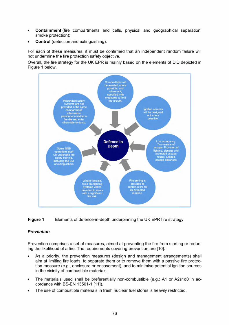
Containment (fire compartments and cells, physical and geographical separation, smoke protection);
Control (detection and extinguishing). For each of these measures, it must be confirmed that an independent random failure will not undermine the fire protection safety objective. Overall, the fire strategy for the UK EPR is mainly based on the elements of DiD depicted in Figure 1 below.
Figure 1 Elements of defence-in-depth underpinning the UK EPR fire strategy Prevention
Prevention comprises a set of measures, aimed at preventing the fire from starting or reduc-ing the likelihood of a fire. The requirements covering prevention are [10]:
As a priority, the prevention measures (design and management arrangements) shall aim at limiting fire loads, to separate them or to remove them with a passive fire protec-tion measure (e.g., enclosure or encasement), and to minimise potential ignition sources in the vicinity of combustible materials.
The materials used shall be preferentially non-combustible (e.g.: A1 or A2s1d0 in ac-cordance with BS-EN 13501-1 [11]).
The use of combustible materials in fresh nuclear fuel stores is heavily restricted.
76
If not class A1 the material must at least be class Bs1d0 or Cs1d0 in accordance with [11] and must not produce dense or toxic smoke. Fire Containment
Fire Compartmentation If a fire starts, despite the preventive measures in place, measures must be taken to limit its spread and to prevent [10]:
Impact on a system whose safety function is required to reach and maintain the safe state of the plant. Fire damage must be restricted to one redundant train in a given safe-ty classified system.
Spreading to other rooms and into emergency exits and disrupting any firefighting provi-sions.
Environmental impact contravening applicable UK Regulations.
Limiting the spread of a fire is achieved by dividing the buildings into fire zones, which use physical or geographical separation principles. Any installed fire barrier must contain the fire so that only one of the redundant trains for a given Safety Class 1 or 2 system may be en-dangered by the fire. The requirements for separation are [10]:
All nuclear safety classified buildings shall be separated from the others by partitions which are classified (at least) EI 1206 if non-load bearing and (at least) REI 1206 if load bearing, as required in the UK EPR Fire Protection Code ETC-F [8] and [9].
Priority shall be given to physical separation (fire containment) rather than spatial sepa-ration. In the same way, priority shall be given to passive measures (fire rated compart-ments) rather than the provision of active systems (i.e., fire extinguishing).
In case of fire, the redundant elements in a Safety Class 1 or 2 system must be protect-ed so that failure is limited to a single train.
Random failure is only to be considered for active equipment items such as fire damp-ers. Fire doors, smoke extraction ducts and floor drains are considered as passive equipment items that are not subject to the random failure requirement.
Table 1 below summarises the different types of fire compartments/cells: Table 1 Different types of fire compartments/cells
Objective Fire Compartment/Cells
Radioactivity containment Type 1a/b
Nuclear safety Type 2
Protected evacuation route Type 3
Facilitation of the Intervention and limiting the unavailability Type 4
Storage Type 5
6 Fire resistances ratings as defined in BS-EN13501-2 [12]: R (for structural resistance), E (for hot gases tight-
ness) and I (for thermal insulation). The time criterion is given in minutes.
77
The principles used take into consideration geographical separation (extinguishing – screen – distance). The containment is justified by taking into account the location of the concentrated fire loads and the combustible material properties. Fire cells must only be used in exceptional circumstances and their effectiveness must be demonstrated on both, fire propagation and radioactive or toxic waste release level.
Where geographical separation is used, it will be justified by a fire hazard analysis.
In general, the UK EPR design considers three fire compartment types [10]:
1. The nuclear safety fire compartment (SFS) - (Type 2): This compartment is created to protect nuclear safety trains from a fire common mode. The partitions of these safety fire compartments shall have a fire resistance rating of at least 120 minutes. Active or passive means of fire protection shall be set up if necessary to guarantee their integrity after this time has passed. The fire resistance of the fire compartment shall be sufficient to withstand the complete combustion of the entire fire load within the compartment. The verification of the adequacy of the compartmentation is described under the sub-section ‘Physical Separation’ below. For the UK EPR, a door monitoring system will be used to detect if a door installed with-in the boundary of a safety fire compartment is left open and will raise adequate alarms (local and in the MCR) to alert the operator to an open or unlatched fire door. The doors, which will be equipped with such monitoring devices, contribute to the following safety functions:
Separation between buildings, Divisional separation, Segregation of safety trains.
2. The access compartment (SFA) - (Type 3): This compartment is intended to enable the personnel to be evacuated in full safety in the event of fire and to provide access to the firefighting teams and allow circulation of personnel for specific plant operation. It corresponds to a protected escape route. The partitions of these compartments shall have a fire resistance consistent with relevant UK regulations for adequate design of escape routes and access for the ‘Fire Services’, at least equal to the rating of the adjacent fire areas, without being less than 60 minutes. These compartments shall strictly minimise fire loads, and as far as possible not contain nuclear safety equipment.
3. The intervention fire compartment (SFI) - (Type 4): This compartment is created when the installation conditions imply the possibility of a flashover, to facilitate the intervention of firefighting crews and limit unavailability of the unit. The partitions of these fire sectors shall have a fire resistance rating suited to the consequences of the fire in the area without being less than 60 minutes. The size of these compartments shall be consistent with the above objective and, wher-ever possible, the same SFI should not be used to cover several building floors. An SFI may be:
included in an SFS, independent of any SFS.
Examples of SFS, SFA and SFI fire compartments within a UK EPR building are shown in Figure 2 and Figure 3 below.
78
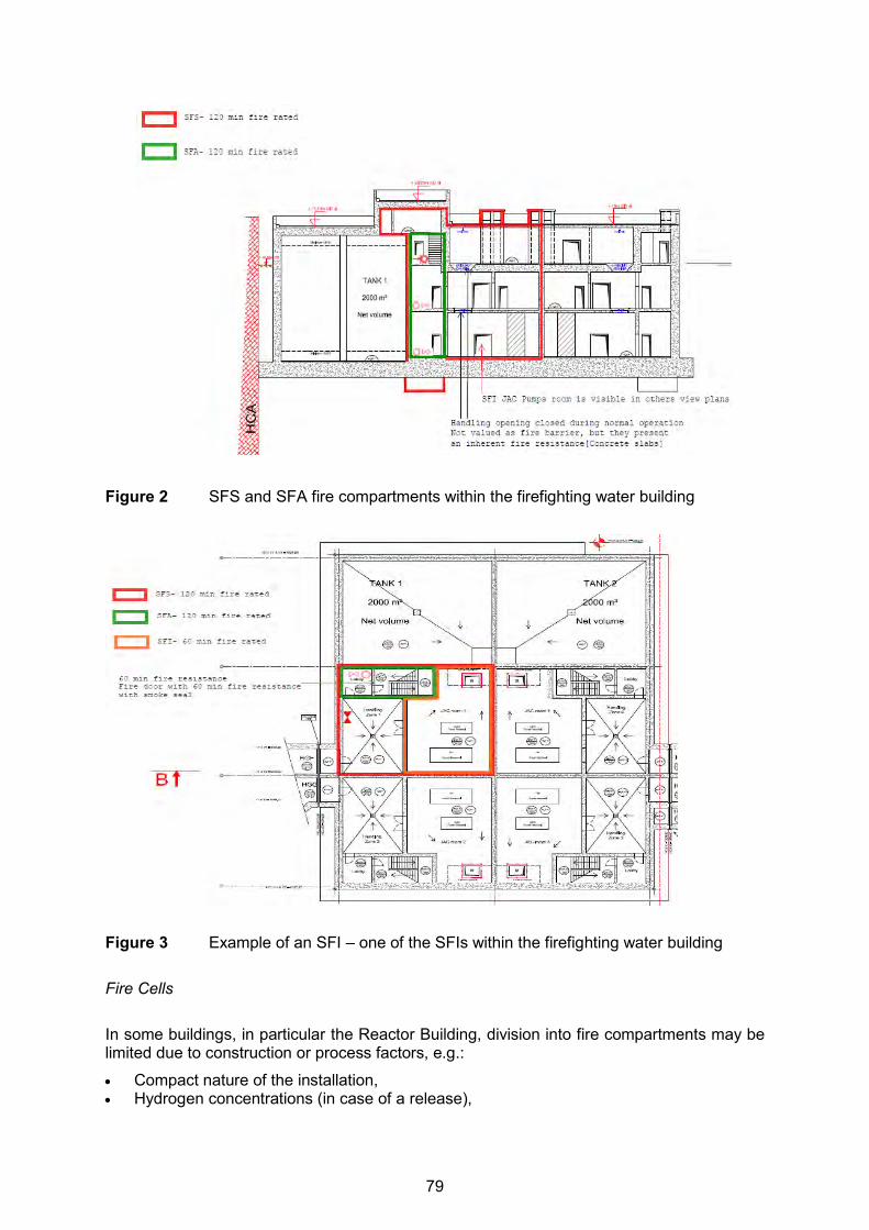
Figure 2 SFS and SFA fire compartments within the firefighting water building
Figure 3 Example of an SFI – one of the SFIs within the firefighting water building Fire Cells
In some buildings, in particular the Reactor Building, division into fire compartments may be limited due to construction or process factors, e.g.:
Compact nature of the installation, Hydrogen concentrations (in case of a release),
79

Steam releases in case of pipe break (rupture).
In this instance, some sections of the buildings may be divided into fire cells [10], where equipment is protected by spatial separation rather than physical barriers. Evidence of non-propagation of fire and avoidance of failures of safety classified equipment, must be estab-lished by assessing all possible modes of fire propagation and combustion products. There are three fire cell types in the UK EPR design [10]: 1. The nuclear safety fire cell (ZFS) - (Type 2):
These cells are created for nuclear safety purposes to protect safety functions needed to reach and maintain the safe state of the plant from common mode failure in case of fire. The partitions of these nuclear safety fire cells shall have a fire resistance at least equal to 120 minutes. Other means of protection shall be set up if necessary to ensure their in-tegrity after this time has passed. As the ZFS contains at least one fire zoning equip-ment or openings which is not fire rated, fire risk analyses have to demonstrate the non-propagation and absence of malfunction of safety related equipment.
2. The unavailability limitation fire cell (ZFI) - (Type 4): These cells are created, when the installation conditions imply the possibility of a flasho-ver and when it is not possible to create an SFI. They are also created when the installa-tion conditions imply the possibility of a localised fire to limit the unavailability of the unit and facilitate the intervention of firefighting crews. The partitions of these fire cells shall have a fire resistance rating adapted to the fire risk analysis and of at least 60 minutes. As the ZFI contains at least one fire zoning equipment or openings which is not fire rat-ed, fire risk analyses have to demonstrate the non-propagation.
3. The maintenance storage cell (ZS) - (Type 5): These cells are created during the design phase to enable the operator to store the equipment and materials required for operation, with the unit in operation, shutdown, outages and maintenance. The partitions of these fire cells shall have a fire resistance rating adapted to the fire risk analysis and of at least 60 minutes. These cells are fitted with fire prevention, detection and fighting means. If necessary, their design is based on the maximum stored fire load fixed by the operator, and takes into account partitioning. The fire load will be strictly controlled by the operator, to ensure it is not in conflict with that set out in the fire safety risk analysis. If possible, when the storage cell is associated with a single room, it will be reserved solely for the needs of the operator. If not possible, technical justification will be provided and sometimes dual coding will be present (e.g., ZS plus SFI due to the presence of flashover type cables). The creation of a storage (or warehousing) cell is appropriate for:
Rooms associated with "job" activities, Rooms dedicated to temporary storage (equipment transfer, repairs and winding-
down of site operations), Rooms dedicated to permanent and temporary storage, Rooms containing radiological sources.
Non-contained Areas Non-contained areas (VNS): These areas are created for rooms or groups of rooms for which no safety or nuclear safety concerns are raised after suitable analyses. They are used to justify monitoring and control of fire load parameters in these rooms. They could also be created to segregate non-controlled area from controlled areas.
80
Physical Separation Separation is performed by the creation of fire compartments or by the use of fire-qualified passive protection features [10]. The fire resistance of these protection devices must be at least equal to the equivalent standard fire rating that bounds the reference fire curve. This reference fire curve is defined by the combustion of materials contained in the room and out-side the enclosure. The fire protection ratings must not be less than the duration of the refer-ence fire in the compartment or cell with the longest fire duration. Where it is not possible to shield part of the equipment in a room from a fire, fire retardant paints can be used on the condition that all the combustible materials present are also coat-ed. Spatial Separation The separation is achieved by creating fire cells or by using fire resistant barriers (e.g., screens) [10]. For spatial separations to be effective, fire risk analyses must conclude that the effects of fire will not spread to the protected equipment (temperature, heat flow, smoke, etc.). Separation by Distance The use of physical distance ensures that a localised fire cannot propagate towards other combustible materials [10]. This is achieved by installing the combustible materials in such a way that the space between them is free from combustible materials. Distance may also be used to prevent a fire causing failure in two redundant items of equipment. This is achieved by ensuring that there is sufficient distance between the combustible materials and at least one of the redundant items for damage to be avoided. The distance required depends on the direct radiated heat and the hot gases generated and transported throughout the space. As a large number of parameters (type of combustible, location in the room, severity of the fire load, etc.) are involved, it is difficult to define a general rule and as such the measures used are subject to specific assessments. Separation Using Thermal Screens This measure, which may be used to supplement the ‘distance’ measure, enables equipment to be shielded from direct radiated heat. A screen is installed whose fire resistance is suffi-cient to withstand the severity and duration of the reference fire. Control of Fire Fire detection and fixed firefighting systems are provided to detect and fight fires and to bring them under control. The control requirements are as follows [10]: The aim of fire detection is to detect fire at an early stage, locate it, trigger the alarm and
initiate automatic actions when required. The fire detection system and features are classified at least Safety Class 3 when required for nuclear safety.
The fire detection system must be operational in all cases where a fire is assumed to occur as far as technically practicable.
81

In terms of firefighting, both manual and fixed extinguishing systems shall be provided. Manual systems consist of portable extinguishers and the provisions for ‘Fire Services’ firefighting. It should be noted that manual firefighting systems are not part of the demonstration of vulnerability analyses.
Vulnerability Analysis In the first step of the analysis, where a fire is postulated in a nuclear safety fire compart-ment (SFS) or in a nuclear safety fire cell (ZFS), operational failure of all the equipment is assumed to occur (apart from those items of equipment which are protected by an approved fire barrier designed to resist the consequences of a fire). The vulnerability analysis [10] shall demonstrate the suppression of any common mode or conclude in the acceptability of the risk incurred. As a general rule, the effects of fire are limited to the investigated fire area, whether it is a compartment, a cell or a division. For cells, the analysis is also conducted between adjacent cells. The analysis is conducted in four steps: Step 1: Search for potential common mode failures; Step 2: Perform a functional analysis; Step 3: Carry out an analysis of the fire risks; Step 4: Treat the risk(s) identified and confirmed in Step 3. Consideration of Random Failures Fire detection equipment is electrical equipment. Therefore, random failures must be taken into account for all the detection equipment required for safety reasons. The pipework of the water circuits and sprinklers are considered as passive equipment items. Therefore, random failure does not need to be taken into account. The following active equipment are to be considered for a single random failure [10]:
Containment: fire stop devices (i.e.: fire dampers); Detection: main detection equipment (as the detectors and their circuits are electrical
equipment); Extinguishing: pumps, controlled valves that change position when the systems and
sprinklers are activated. Design Verification Studies The design verification for protection against internal fires is a deterministic demonstration that the unit has acceptable protection against this hazard. It is performed according to the methodology described below [13]: First Phase: Design studies are performed to define the fire compartments building by building. The justi-fication of the fire zoning is provided for all nuclear safety significant buildings. Second Phase: This phase consists of checking that the fire compartments are adequately implemented and consistent with the safety objective. It includes modelling the fire compartments on the basis of the EPRESSI method [14].
82
Third Phase: The objective of this phase, which is based on the implementation of the vulnerability studies described in the section above, is to either demonstrate the suppression of any common mode or conclude in the acceptability of the risk incurred. PRODUCTION OF HAZARD PROTECTION SCHEDULES The development of the HPSs, for the UK EPR design, is based on a methodology [15] de-veloped to provide guidance on the methods used for design basis safety analyses with re-spect to internal or external hazards. The methodology relies mainly on using a qualitative approach, but employs quantitative supporting information where necessary to demonstrate that the outcome is ALARP in terms of nuclear safety risk. An important part of the IHs safety analyses, conducted thus far, is presented within the basic design hazard protection schedules (BD-HPSs) for [IH; Building(s)] pairs. The main technical objective of these BD-HPSs is to contribute to the overall demonstration of the ro-bustness of the UK EPR basic design before starting the detailed design studies. It is also an opportunity to consider any relevant operational experience from the other EPRs currently under construction throughout the world (Finland, France and China). It is stated the first section (2nd paragraph) of this paper that "External and internal hazards that could affect the plant must be identified, and provision made to ensure that the risk from hazards is commensurate with the overall frequency and release targets". To achieve this objective it must be demonstrated that the three main safety functions (i.e., control of fuel re-activity; fuel heat removal; confinement of radioactive materials) can be fulfilled and the plant brought and maintained at a safe shutdown state following the occurrence of internal haz-ards. The need to provide such a demonstration leads, in addition to the hazards design ap-proach, to the production of BD-HPSs that identify the main safety functions potentially af-fected by the considered IHs. Thus, in order to ensure that the process is comprehensive, logically consistent and relevant to the UK safety assessment context, identification of all reasonably foreseeable hazard initiating events (HIEs) must be conducted. This is followed by the identification of the required hazard safety functions (HSFns) needed to protect against the adverse consequences of considered HIEs. Such HSFns are categorised (in accordance with the UK EPR categorisation criteria [16] us-ing the guidance in the BD-HPS production methodology [15], and the hazard safety fea-tures (HSFs) - SSCs that fulfil the HSFns - are classified with respect to the importance of their contribution to nuclear safety and also in accordance with [16]. This is a similar process to the production of the main fault and protection schedule for the UK EPR design. This ap-proach is compatible with the expectation that all initiating events be given equal attention in a fault schedule, regardless of whether they relate to an internal fault (i.e.: an operational failure resulting in a core transient or direct radiological release) or an internal or external hazard. The following procedural steps are intended to align directly with production stages and for-matting defined in the BD-HPSs production methodology [15]:
Step 1: Identification and classification of buildings requiring hazard safety analyses; Step 2: Identification of HIEs for which hazard analyses are required for the buildings
identified in Step 1; Step 3: Identification and categorisation of the required HSFns and classification of their
associated HSFs. Two examples extracted from the preliminary “Internal Fires” BD-HPS produced for the Nu-clear Auxiliary Building (HN) and the Diesel Building (HD) [17] are presented Table 2 and Table 3 below.
83
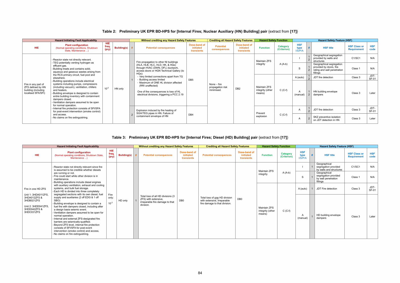
Table 2: Preliminary UK EPR BD-HPS for [Internal Fires; Nuclear Auxiliary (HN) Building] pair {extract from [17]}
Hazard Initiating Fault Applicability Without crediting any Hazard Safety Features Crediting all Hazard Safety Features Hazard Safety Function Hazard Safety Feature (HSF)
HIE Plant configuration
(Normal operating conditions, Shutdown State, Maintenance ...)
HIE freq. (pry)
Building(s) # Potential consequences Dose-band of
initiated transients
Potential consequences
Dose-band of initiated
transients Function Category
(Criterion) HSF type
I/S/P/A # HSF title HSF Class or
Requirement HSF code
Fire in any part of ZFS defined by HN building (including localised SFA/SFI)
- Reactor state not directly relevant. - TEG potentially venting hydrogen as effluent gas.
- Building treats and contains solid, aqueous and gaseous wastes arising from the RCS primary circuit, fuel pool and elsewhere.
- Building operations include electrical systems including pumps, compressors (including vacuum), ventilation, chillers and heaters.
- Building envelope is designed to contain entire building inventory with containment dampers closed.
- Ventilation dampers assumed to be open for normal operation.
- Internal fire protection consists of SFI/SFA for post-event intervention (smoke control) and access.
- No claims on fire extinguishing.
10-2 HN only
1
Fire propagation to other NI buildings (HLA, HLB, HLC, HLD, HK, & HQx) through HVAC (DWN, DFL) ductwork, access doors or HGN Technical Gallery (to HQx): - Very limited connections apart from TG - Building access limited - Maximum of ONE HL division affected
(RRI unaffected) One of the consequences is loss of HL electrical divisions, triggering a PCC 2.19
DB5
None – fire propagation risk minimised.
DB2
Maintain ZFS integrity
A (A-b)
I 1 2
Geographical segregation provided by walls and structures
C1/SC1 N/A
S 1 2
Geographical segregation provided by doors, fire rating and wall penetration fillings
Class 1 N/A
Maintain ZFS integrity (other means)
C (C-f)
A (auto) 1 2 JDT fire detection Class 3 JDT-
SF-01
A (manual)
1 2
HN building envelope dampers Class 3 Later
2
Explosion induced by fire heating of SGH/TEG pipes in HN. Failure of containment envelope of HN
DB4 Prevent explosion C (C-f)
A 1 2 JDT fire detection Class 3 JDT-
SF-01
A 2 SKZ preventive isolation on JDT detection in HN Class 3 Later
Table 3: Preliminary UK EPR BD-HPS for [Internal Fires; Diesel (HD) Building] pair {extract from [17]}
Hazard Initiating Fault Applicability Without crediting any Hazard Safety Features Crediting all Hazard Safety Features Hazard Safety Function Hazard Safety Feature (HSF)
HIE Plant configuration
(Normal operating conditions, Shutdown State, Maintenance ...)
HIE freq. (pry)
Building(s) # Potential consequences Dose-band of
initiated transients
Potential consequences Dose-band of
initiated transients
Function Category (Criterion)
HSF type
I/S/P/A # HSF title HSF Class or
Requirement HSF code
Fire in one HD ZFS Unit 1: 3HDA011ZFS, 3HDA012ZFS & 3HDB021ZFS Unit 2: 3HDD041ZFS, 3HDD042ZFS & 3HDC031ZFS
- Reactor state not directly relevant since fire is assumed to be credible whether diesels are running or not.
- Fire could start while other division is in maintenance.
- Building operations include diesel engines with auxiliary ventilation, exhaust and cooling systems, and bulk fuel storage.
- Each HD is divided into three completely segregated sections with its own diesel, fuel supply and auxiliaries (2 off EDG & 1 off SBO)
- Building envelope is designed to contain a fuel fire with dampers closed, including after a design basis seismic event.
- Ventilation dampers assumed to be open for normal operation.
- Internal and external ZFS-designated fire barriers are seismically-qualified.
- Beyond ZFS level, internal fire protection consists of SFI/SFA for post-event intervention (smoke control) and access.
- No claims on fire extinguishing.
Fire only: 10-3
HD only 1
Total loss of all HD divisions (3 ZFS) with extensive, irreparable fire damage to that division.
DB0 Total loss of one HD division with extensive, irreparable fire damage to that division.
DB0
Maintain ZFS integrity A (A-b)
I 1 Geographical segregation provided by walls and structures
C1/SC1 N/A
S 1
Geographical segregation provided by wall penetration fillings
Class 1 N/A
Maintain ZFS integrity (other means)
C (C-f)
A (auto) 1 JDT Fire detection Class 3 JDT-SF-01
A (manual) 1 HD building envelope
dampers Class 3 Later
84
CONCLUSIONS This paper presents a summary of the approach adopted for the deterministic safety analysis of the “internal fires” hazard that is being performed for the UK EPR design. The main objec-tive of the analysis is to demonstrate that sufficient SSCs remain available to permit a safe shutdown state of the plant to be reached and maintained, and limit any radiological releases to below those considered to arise from PCC events (internal faults) occurring at frequencies equivalent to the “internal fires” hazard frequency. To achieve such objective, an overall four steps internal hazards design analysis approach was developed and implemented.
Step 1: IHs identification including the consideration of credible combined or consequen-tial hazards and the setting up of safety requirements.
Step 2: IHs impact quantification (e.g., specific loads and environmental conditions), and design basis protection of structures, systems and components against the impact.
Step 3: Design verification against IHs to confirm that the safety requirements have been fulfilled. This is systematically performed on a case-by-case basis with the use of deterministic studies, such as building and equipment response, functional impact in-cluding consideration of consequential internal faults, etc.
Step 4: Production of hazard protection schedules (which consider and complement the design verification analyses.
Regarding the “internal fires” hazard, it is expected that complete implementation of the above steps can provide a demonstration that classified safety systems can achieve their design objectives by minimising the occurrence of “internal fires” and by mitigating their po-tential consequences. In effect, a set of general safety principles related to “internal fires” protection have been identified and compliance of the UK EPR design with those principles is required. To achieve such compliance, three groups of defence in depth measures against the impacts of “internal fires” are adopted for the UK EPR design:
Prevention (prevent fires from starting, prevention of spreading); Containment (fire compartments and cells, physical and geographical separation,
smoke protection); Control (detection and extinguishing).
The initial results from the implementation of the above measures during the basic studies phase of the UK EPR design show that:
“Internal fires” effects are limited so that sufficient structures, systems and components remain available to permit a safe shutdown state of the plant to be reached and main-tained, and any potential radiological releases are kept below acceptable limits.
Non-redundant systems and equipment, which perform the required nuclear safety func-tions, are protected against the effects of “internal fires” to ensure continuous and safe operation of the plant.
In the event that the main control room becomes inhabitable due to “internal fires”, the accessibility and habitability of the remote shutdown station can be assured.
Adequately categorised hazard safety functions and associated classified hazard safety features are identified and implemented in the UK EPR design to reduce the risks and effects of “internal fires” to as low as reasonably practicable.
These initial results confirm that the UK EPR fire protection design objective is adequately met, and therefore the risks to workers and general public are demonstrated to be as low as reasonably practicable.
85

REFERENCES
[1] EDF Energy Plc., Nuclear New Build Generation Company Ltd. (NNB GenCo), HPC PCSR3 (1st Iteration), Sub-Chapter 3.1, “General Safety Principles”, HPC-NNBOSL-U0-000-RES-000161, Revision A, BPE Status, June 2015.
[2] EDF Energy Plc., Nuclear New Build Generation Company Ltd. (NNB GenCo), HPC PCSR3 (1st Iteration), Sub-Chapter 13.2 “Internal Hazards Protection”, Section 13.2.1 “Safety Requirements and Design Basis Common to all Internal Hazards”, HPC-NNBOSL-U0-000-RES-000141, Revision B, BPE Status, June 2015.
[3] EDF Energy Plc., Nuclear New Build Generation Company Ltd. (NNB GenCo), HPC PCSR3 (1st Iteration), Sub-Chapter 13.2 “Internal Hazards Protection”, Section 13.2.7 “Protection against Internal Fires”, Sub-Section 13.2.7.0 “Safety Requirements”, HPC-NNBOSL-U0-000-RES-000141, Revision B, BPE Status, June 2015.
[4] The UK “Regulatory Reform (Fire Safety) Order 2005, No. 1541, Statutory Instruments, 2005, http://www.legislation.gov.uk/uksi/2005/1541/contents/made.
[5] The UK “Construction (Design and Management) Regulations 2015, No. 51, Statutory Instruments, April 2015, http://www.legislation.gov.uk/uksi/2015/51/contents/made.
[6] Health and Safety Executive (HSE), The UK Dangerous Substances and Explosive At-mospheres Regulations 2002, No. 2776, Statutory Instruments, 2002, http://www.hse.gov.uk/fireandexplosion/dsear.htm
[7] The UK Control of Major Accident Hazards Regulations 2015, No. 483, Statutory Instruments, June 2015, http://www.legislation.gov.uk/uksi/2015/483/pdfs/uksi_20150483_en.pdf.
[8] EDF SA, The EPR Technical Code for Fire Protection, ENGSIN050312, Revision B, August 2007 (English version which corresponds to Version G of the ETC-F).
[9] EDF SA, ETC-F Version G Companion Document for EPR/UK Context, ENGSIN120171. Revision A, December 2012.
[10] EDF Energy Plc., Nuclear New Build Generation Company Ltd. (NNB GenCo), HPC PCSR3 (1st Iteration), Sub-Chapter 13.2 “Internal Hazards Protection”, Section 13.2.7 “Protection against Internal Fires”, Sub-Section 13.2.7.1 “Design Basis”, HPC-NNBOSL-U0-000-RES-000141, Revision B, BPE Status, June 2015.
[11] British Standard, BS EN 13501-1, “Fire classification of construction products and build-ing elements – Part 1: Classification using data from reaction to fire tests”, British Standards Institute, 2007, and A1, 2009.
[12] British Standard, BS EN 13501-1, “Fire classification of construction products and build-ing elements – Part 2: Classification using data from fire resistance tests, excluding ven-tilation systems”, British Standards Institute, 2007, and A1, 2009.
[13] EDF Energy Plc., Nuclear New Build Generation Company Ltd. (NNB GenCo), HPC PCSR3 (1st Iteration), Sub-Chapter 13.2 “Internal Hazards Protection”, Section 13.2.7 “Protection against Internal Fires”, Sub-Section 13.2.7.2 “Design Verification”, HPC-NNBOSL-U0-000-RES-000141, Revision B, BPE Status, June 2015.
[14] EDF SA, Principle of the EPRESSI Method (English version of ENGSIN070401, Revi-sion A), ENGSIN080155 Revision A, May 2008.
[15] EDF SA, Guidance for the Development of the Hazard Protection Schedules at the Basic Design Stage of HPC Project, ECESN140677, Revision A, BPE Status, Septem-ber 2014.
86

[16] EDF Energy Plc., Nuclear New Build Generation Company Ltd. (NNB GenCo), HPC PCSR3 (1st Iteration), Sub-Chapter 3.2, “Classification of Structures, Systems, Safety Features and Components”, HPC-NNBOSL-U0-000-RES-000129, Revision A, BPE Sta-tus, June 2015.
[17] EDF SA, Nuclear Island Basic Design Hazard Protection Schedule: Internal Fires, ECESN140987, Revision A, BPE Status, December 2014.
87
23rdInternational Conference on Structural Mechanics in Reactor Technology (SMiRT 23) - 14h
International Post-Conference Seminar on “FIRE SAFETY IN NUCLEAR POWER PLANTS AND INSTALLATIONS“
OVERVIEW OF INTERNAL FIRE HAZARDS ASPECTS OF ABWR DESIGN FOR UNITED KINGDOM
Kazuhiro Yoshikawa, Hiroki Kawai
Hitachi-GE Nuclear Energy, Ltd.,
3-1-1, Saiwai-cho Hitachi-shi, Ibaraki 317-0073, Japan ABSTRACT The ABWR (Advanced Boiling Water Reactor) is a generation III+ reactor, the most modern operational generation of nuclear power plants. The UK ABWR design is proposed for de-velopment and construction in the United Kingdom (UK), and under review by the Office for Nuclear Regulation (ONR) through Generic Design Assessment (GDA). The UK ABWR de-sign has mainly two types of the safety system: “preventing” and “mitigating” a fault and their consequences. The prevention of internal hazards starts with design processes and proce-dures. These processes lead to limiting the sources of potential hazards. The mitigative safety systems are required to ensure the fundamental safety functions (FSFs): control of reactivity, Fuel cooling, long term heat removal, confinement/containment of radioactive ma-terials, and others. Implementation of the safety philosophy is based upon redundant and di-verse safety systems that deliver the FSFs. Three mechanical divisions are provided, each of which contains redundant systems, structures, and components (SSCs) capable of carry-ing out all the FSFs. The safety divisions are separated by robust barriers which act to con-tain a hazard in an affected division and prevent the spread of the hazard to a different divi-sion. The deterministic assessments and the hazard schedule argue that the rooms contain-ing SSCs providing the FSFs are located in different fire safety divisions. The approach to maintaining the FSFs during and after internal fires is to ensure fires do not spread beyond that division to affect redundant equipment in other divisions. During the GDA process, it is demonstrated that generally barrier compartmentation (the divisional barrier walls, ceilings and floors) is sufficient to contain the postulated fires. The UK ABWR design has sufficient capability of withstanding the postulated internal fire hazard to achieve the FSFs. Further development is being undertaken with feedback in the GDA licensing review process with ONR. INTRODUCTION This paper discusses the internal fire hazards aspects of the UK ABWR design, which is un-der review in the GDA assessment process. The GDA assessment process for the UK ABWR is now in Step 3, and the Design Acceptance Confirmation (DAC) is targeted for 2017. In this paper, an introduction of the UK ABWR design and a summary of the safety design philosophy regarding internal fire hazards is described. OVERVIEW OF THEE UK ABWR PROJECT ABWR Design The UK ABWR is a nuclear reactor design proposed for development and construction in the UK. The UK ABWR is being developed and offered in the UK by Hitachi-GE Nuclear Energy, Ltd. (Hitachi-GE). The design baseline of the UK ABWR is the ABWR design, which is a
88

generation III+ reactor, the most modern operational generation of nuclear power plants. The ABWR is operational at three sites in Japan: two units at Kashiwazaki-Kariwa; one unit at Hamaoka and one unit at Shika. There are a further four units under construction, two units at Lungmen in Taiwan, and one unit at both Shimane and Ohma in Japan. At full power, a single ABWR unit produces around 1350 MWe of electricity – enough to power more than two million homes. The ABWR design has been developed since 1985, in collaboration with various international partners and support from power companies with experience in BWR plant operation. The main technological features employed are as follows:
Large scale, highly efficient plant, Highly economical reactor core, Reactor coolant recirculation system driven by internal pumps, Advanced control rod drive mechanism, Overall digital control and instrumentation (I&C), Reinforced concrete containment vessel.
These features constitute a highly-functional, enhanced-safety nuclear reactor system, with a compact, easy-to-operate, and efficient turbine of excellent performance. For information on the ABWR, please see the website (http://www.hitachi-hgne-uk-abwr.co.uk/index.html). The key specifications of typical ABWR design are shown below.
Plant output: 1,350 MWe class Reactor thermal output: 3,926 MWt Reactor rated pressure: 7.07 MPa Reactor core fuel assemblies: 872 Control rods: 205 rods Recirculation system: internal pump system Control rod drive: hydraulic / electric motor drive method Primary containment vessel (PCV):reinforced concrete with built-in liner ECCS*/PCV cooling system: 3 divisions Residual heat removal system: 3 divisions * ECCS: Emergency Core Cooling System
Figure 1 Conceptual view of ABWR
89
Generic Design Assessment (GDA) Nuclear energy is highly regulated to ensure that the highest levels of safety, security and environmental protection are maintained at all times. For new nuclear builds in the UK, the first stage of this is a rigorous assessment of the reactor design by UK regulators, known as GDA. The GDA is the process by which the UK nuclear regulators assess the potential suitability of a nuclear reactor design for development at an unspecified location in the UK, considering safety and environmental impact considerations. It is not an assessment of the principles of nuclear energy, but of the design of the UK ABWR plant itself. Passing the GDA is an important step in the process towards developing an operational station, but does not in itself give any ‘permission’ to develop. A Nuclear Site License is still required, as are environmental permits. Although the GDA may inform elements of these assessments, it does not replace them. Power station developers must also go through the full planning process in order to gain a Development Consent Order. The GDA is broken down into a number of steps, each of which entails additional submissions to the regulators. A significant number of these submissions will be published via the website (http://www.hitachi-hgne-uk-abwr.co.uk/index.html) and Hitachi-GE invites comments or questions on them. A detail description of design philosophy against internal hazards including fire of UK ABWR is provided as Pre-Construction Safety Report [1] on the website. UK ABWR SAFETY DESIGN PHILOSOPHY Safety Functions The design of the UK ABWR is primarily based on providing segregated, redundant and diverse safety systems to protect against faults. The safety systems for the UK ABWR can be divided into two main groups: the systems that prevent faults and abnormal conditions in the facilities, and the systems that mitigate the consequences of a fault and abnormal events. The safety systems of the UK ABWR design are required to ensure the following fundamental safety functions are still delivered when a fault occurs:
FSF1: Control of reactivity, particularly the ability to achieve emergency reactor shut-down,
FSF2: Fuel cooling, i.e. all systems whose function is to prevent damage to fuel from overheating,
FSF3: Long term heat removal, including removal of decay heat and containment vent-ing systems,
FSF4: Confinement/Containment of radioactive materials, and FSF5: Others, including remote shutdown capabilities, instrumentation and monitoring,
alternative power supplies, emergency measures.
In order to achieve these fundamental safety functions throughout most of the UK-ABWR design, the implementation of this safety philosophy is based upon redundant and diverse safety systems that deliver the fundamental safety functions. Three mechanical divisions are provided, each of which contains redundant systems, structures and components (SSCs) capable of carrying out all the fundamental safety functions. The safety divisions are separated by robust barriers (designed to Nuclear Class 1) which act to contain a hazard in an affected division and prevent the spread of the hazard to a different division. The internal hazards safety case includes measures and systems designed to prevent internal hazards
90
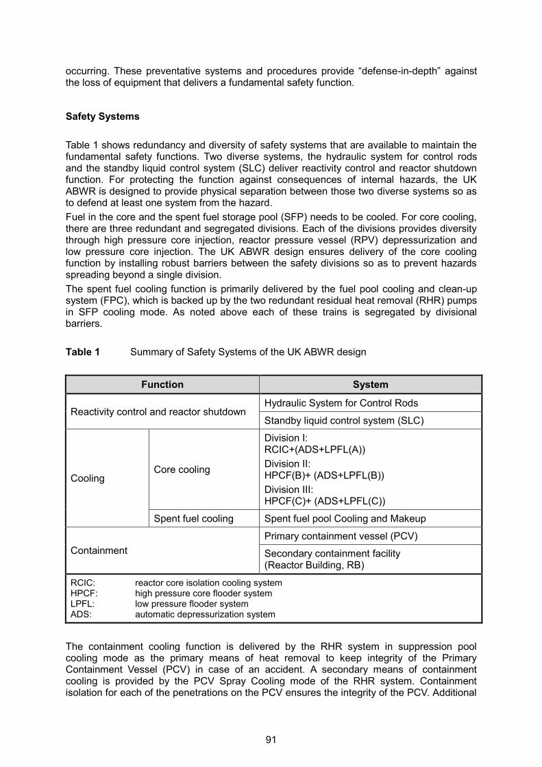
occurring. These preventative systems and procedures provide “defense-in-depth” against the loss of equipment that delivers a fundamental safety function.
Safety Systems Table 1 shows redundancy and diversity of safety systems that are available to maintain the fundamental safety functions. Two diverse systems, the hydraulic system for control rods and the standby liquid control system (SLC) deliver reactivity control and reactor shutdown function. For protecting the function against consequences of internal hazards, the UK ABWR is designed to provide physical separation between those two diverse systems so as to defend at least one system from the hazard. Fuel in the core and the spent fuel storage pool (SFP) needs to be cooled. For core cooling, there are three redundant and segregated divisions. Each of the divisions provides diversity through high pressure core injection, reactor pressure vessel (RPV) depressurization and low pressure core injection. The UK ABWR design ensures delivery of the core cooling function by installing robust barriers between the safety divisions so as to prevent hazards spreading beyond a single division. The spent fuel cooling function is primarily delivered by the fuel pool cooling and clean-up system (FPC), which is backed up by the two redundant residual heat removal (RHR) pumps in SFP cooling mode. As noted above each of these trains is segregated by divisional barriers. Table 1 Summary of Safety Systems of the UK ABWR design
Function System
Reactivity control and reactor shutdown Hydraulic System for Control Rods
Standby liquid control system (SLC)
Cooling Core cooling
Division I: RCIC+(ADS+LPFL(A)) Division II: HPCF(B)+ (ADS+LPFL(B)) Division III: HPCF(C)+ (ADS+LPFL(C))
Spent fuel cooling Spent fuel pool Cooling and Makeup
Containment Primary containment vessel (PCV)
Secondary containment facility (Reactor Building, RB)
RCIC: HPCF: LPFL: ADS:
reactor core isolation cooling system high pressure core flooder system low pressure flooder system automatic depressurization system
The containment cooling function is delivered by the RHR system in suppression pool cooling mode as the primary means of heat removal to keep integrity of the Primary Containment Vessel (PCV) in case of an accident. A secondary means of containment cooling is provided by the PCV Spray Cooling mode of the RHR system. Containment isolation for each of the penetrations on the PCV ensures the integrity of the PCV. Additional
91
containment function is delivered by secondary containment facility, which is supported by redundant divisions of the standby gas treatment system (SGTS). SGTS keeps the atmosphere inside the RB to be negative pressure for preventing release of radiological substances to the public from the RB. The safety systems summarized in Table 1 are supplemented by an independent set of nuclear safety mitigation equipment that can be used for core cooling, decay heat removal and maintaining primary containment. These are located in a seismically qualified Backup Building (BB), which will be sufficiently apart from the RB as severe accident management facility. In case of beyond design based accidents, they will perform providing supplemental safety function. Prevention and Limitation of Severity of Internal Hazards The prevention of internal hazards starts with the design processes and procedures. These processes lead to limiting the sources of potential hazards. Codes and standards, as well as design guides are used to appropriately design equipment and structures, and develop a layout to prevent the occurrence of an internal hazard, and prevent the impacts of internal hazards whenever possible. If all the prevention measures were to fail, the general approach to ensure protection of SSCs which deliver the FSFs is to limit the impacts of internal hazards to within the redundant division of the safety system using robust barrier compartmentation. The specific internal hazard assessments identify and assess the prevention measures included in the design. Based on the importance of the prevention measures to maintaining the Fundamental Safety Functions and reducing risk ALARP, classification of these measures are determined. As stated above, significant importance and higher classification is placed on mitigative measures and most of the preventative measures are classified as defense in depth. Some internal hazards have measures to limit severity of the hazards to reduce consequences or risk of the hazards (e.g. fire fighting). Mitigation of Internal Hazards If all the prevention measures were to fail, the general approach to ensuring protection of SSCs which deliver the fundamental safety functions is to limit the impacts of an internal hazard to within the redundant division of the safety system using robust barrier compartmentation. In some areas, it is necessary to consider one internal hazard causing a second internal hazard due to the proximity of these hazards. In these combined hazard cases, other prevention and mitigation measures may be necessary. Internal hazards claims are achieved by the following design features:
1. SSCs of the fundamental safety functions that require redundancy are located in separate safety division areas fully enclosed with appropriately designed barriers (floor, ceiling, wall, etc.). Divisional barriers have been designed to withstand the potential fire impact and overpressure consequences of the various internal hazards that they may be exposed to.
2. There are some areas where the functional requirements do not allow the above segregation provisions to be made. These are the primary containment vessel (PCV), the main control room (MCR), the main steam tunnel (MST) and, in some cases, redundant equipment is somewhere located in another division for reliability purposes following a hazard. These exceptions to segregation are justified on a case by case basis.
92

Penetrations Penetrations of the barriers between redundant divisions are minimized. Any devices for closing penetrations such as doors, ductwork, hatches, and pipework and cable entry seals, which form part of a barrier, are appropriately designed with the same internal hazards, including fire, resistance ratings as the overall barrier. If a barrier cannot ensure segregation of redundant SSCs, then other measures are considered, including the following for internal fire:
Administrative controls on the amount of materials that may cause an internal fire; Separation by individual room walls or equipment barriers which are not claimed as in-
ternal fire divisional barriers; Separation of equipment by distance, without intervening materials that may cause an
internal fire; Local passive protection that may prevent internal fire affecting the equipment required
to function. Where door access through a claimed Nuclear Safety Class barrier is required, two sets of doors separated by a lobby will be provided wherever reasonably practicable. Any remaining single doors will be fitted with an alarm system to alert operational staff where doors are left open or fail to close. Divisional Separation Exceptions Significant importance is placed on systems that mitigate the effects of internal hazards including fire. There are three redundant and independent divisions of equipment to maintain the fundamental safety functions. Generally for internal fire, this is provided by passive barrier compartmentation designed such that internal fire and their effects are limited to one safety division. The equipment within the different systems is grouped together within each safety division and the safety divisions are segregated from one another by robust barriers. These barriers provide the principal means of maintaining the fundamental safety functions against the effect of internal fire. However, there are exceptions where multiple divisions of equipment or instruments are located in the same area or room. There are rooms throughout the nuclear island that contain multiple divisions because there may be specific design requirements to provide diversity; these areas are referred to as exceptions to segregation. Such exceptions to divisional segregation have been considered. These areas will be assessed to ensure that internal fire in those areas do not compromise the fundamental safety functions. In most cases of exceptions to segregation, the design of the reactor protection systems provide robustness and enhance the reliability of safety system actuation to fulfill the fundamental safety functions. The areas with exceptions to segregation include the PCV, the MST and the MCR. Note that nuclear safety relates not only to the safe operation or shutdown of the reactor but also to the containment of contamination and radiation such that the radiological risk to workers and the public is as low as reasonably practicable (ALARP). FIRE SAFETY DESIGN APPROACH The following sections discuss the fire safety design approach of the UK ABWR. The key piece of legislation under the UK law is the Health and Safety at Work, etc. Act 1974 (HSWA) [2], which requires consideration of both the direct effects of fire on people (‘conventional fire
93

safety’) and the effects of ionizing radiation on people resulting from fire events (‘nuclear fire safety’). For UK ABWR design, the following regulatory regime is to be considered: Nuclear Fire Safety 1. The ‘Nuclear Installations Act 1965’ (http://www.legislation.gov.uk/ukpga/1965/57, as
amended) is the primary regulation, under UK law, for the protection of people (both employees and the public) from harmful effects of radiation.
2. The ‘Ionizing Radiation Regulations 1999’ (IRRs, http://www.legislation.gov.uk/uksi/1999 /3232/contents/made) are applied to nuclear licensed sites (and others containing radiological material) to regulate radiation protection. The IRRs have limited impact on the fire hazard, although some of the Basic Safety Levels (BSLs) used in deterministic analysis of hazards are legal limits in the IRRs.
3. The ‘Radiation (Emergency Preparedness and Public Information) Regulations 2001’ (REPPIR, http://www.hse.gov.uk/radiation/ionising/reppir.htm) require a framework for the protection of the public through emergency preparedness for radiation accidents with the potential to affect members of the public and provision of information to the public.
4. Guidance on the requirements for UK nuclear safety cases is set out in the ONR Safety Assessment Principles and Technical Assessment Guides (TAGs).
5. The Safety Assessment Principles (SAPs), which were developed for ONR use but have been made publically available, provide ONR inspectors with a framework for making consistent regulatory judgments on nuclear safety cases. Practically, the SAPs also provide guidance for design decisions of applications for and holders of Nuclear Site License.
6. The Technical Assessment Guides (TAGs) provide additional guidance to inspectors, with the relevant TAG being internal hazards, NS-TAST-GD-014, updated April [3]. This TAG refers directly to the more detailed International Atomic Energy Agency (IAEA) guidance within NS-G-1.7 [4] and NS-G-2.1 [5] within the UK context.
7. The SAPs reflect, and have been benchmarked against, the IAEA guidance. However, due to the UK’s goal-setting legal framework for health and safety, the IAEA requirements are not implemented in a prescriptive manner.
8. The TAG and IAEA guidance documents have been used by Hitachi-GE to assess the UK ABWR design to ensure it meets the expectation of the UK regulators.
Conventional Fire Safety 1. The ‘Regulatory Reform (Fire Safety) Order’ (RRO), cf. http://www.legislation.gov.uk/uksi
/2005/1541/contents/made, is the major piece of the UK fire legislation and covers general fire precautions and other fire safety duties. The RRO requires fire precautions to be put in place ‘where necessary’ and to the extent that it is reasonable and practicable and covers the design and occupation of buildings.
2. ‘The Building Regulations 2010’, http://www.legislation.gov.uk/uksi/2010/2214/contents/ made embodies the description given in the ‘Building Act 1984’, http://www.legislation.gov.uk/ukpga/1984/55, and generally apply to the design and construction of buildings, rather than their occupation. However an exemption in the Building Regulations is included for “Any building (other than a building containing a dwelling or a building used for office or canteen accommodation) erected on a site in respect of which a license under the Nuclear Installations Act 1965 is for the time being in force.” Therefore the Building Regulations will not apply to the GDA for the UK ABWR.
94
3. The ‘Dangerous Substances and Explosive Atmospheres Regulations 2002’ (DSEAR, cf. http://www.legislation.gov.uk/uksi/2002/2776/contents/made) regulate dangerous substances used or present at work that could, if not properly controlled, cause harm to people as a result of a fire or explosion. Hitachi-GE is assessing the UK ABWR design for compliance with these regulations. An example is control of hydrogen both generated inside the reactor and used for generator cooling.
4. ‘BS 9999:2008: Code of practice for fire safety design, management and construction of buildings’ http://shop.bsigroup.com/en/ProductDetail/?pid=000000000030158436) is an accepted way of meeting the requirements of the RRO, and is therefore used as the basis for design in UK ABWR. As a code of practice, it contains elements of good fire safety management and design practice covering life safety and to enhance property protection and business continuity.
5. As with the majority of British Standards the contents are recommendations and not requirements. As such the UK ABWR design will follow the recommendations in BS 9999 in so far as in reasonably practicable and where departures from the recommendations are identified, compliance with the regulatory functional requirements (contained within the RRO) will be demonstrated through a structured approach. Some changes to the standard ABWR design have been applied for compliance with BS 9999, e.g. addition of fire fighting lobbies.
6. ‘BS 7974-1:2001: Application of fire safety engineering principles to the design of buildings - Code of practice’, cf. http://shop.bsigroup.com/ProductDetail/?pid=000000000 030028692 along with eight published documents, provides guidance on the use of fire engineering techniques to provide a structured approach to meeting the functional requirements of the RRO. These documents provide guidance to Hitachi-GE for assessing fire hazards and determining the robustness of barriers against a fire hazard.
FIRE SAFETY DESIGN BASIS Internal fire hazards can occur within the site boundary and inside the buildings of the UK ABWR. Sources of combustible inventory include fuel oil, lubrication oil, cables and transient combustibles. Fires may also arise from other internal and external hazards. The internal fire claim of the UK ABWR design is defined as follows: “The consequences of any internal fire hazard are limited to one safety division in principle.” There is suitable and sufficient fire compartmentation in place to ensure that the consequences of any fire event will be contained within the safety division of origin. Thus, a fire will not affect equipment within more than one division in principle. The above internal fire claims will be achieved in the UK ABWR design by:
a. Limitation of the fire loading, b. Limiting the potential ignition sources so as to prevent fires from starting, c. Limiting the severity of fires that do start, d. Mitigating the consequences of severe fires (principally through fire compartmentation).
The number of fire sources is limited as far as possible by minimizing combustible quantities and storing potentially combustible materials in areas with limited or protected ignition sources. The sections below describe the design aspects that prevent fires and mitigate the consequences. Fire Prevention The UK ABWR design includes a number of features that prevent fires as follows:
95

1. Non-combustible materials or fire retardant materials are used for interior materials where possible.
2. Pipework containing flammable liquids is welded and sealed, and double walled where necessary.
3. Equipment containing flammable liquids is pressure tested. 4. Any leakage is detected by liquid level monitoring and captured. 5. The area around equipment containing large quantities of flammable liquids includes
bunds that prevent spread of the spill. These bunds are designed to contain additional liquid from any fire fighting water/foam.
6. Low combustibility fluids are used if practicable. 7. Electrical systems use breakers and fuses to prevent overloading. 8. Dry-type transformers are used where the transformer is located within a building. 9. Electrical equipment in the areas around systems containing flammable liquids and
gases, and the hydrogen supply systems have been appropriately rated per the Hazardous Area Classification guidelines.
10. Cables specified for the UK-ABWR meet standards for flame spread and smoke generation under fire conditions.
11. Cables are installed in steel cable trays, conduits or other non-combustible cable supports and are appropriately spaced.
12. Insulating lagging provided for pipework with hot surfaces. 13. Pipework for systems containing hydrogen is designed to prevent leakage and failure. 14. Pipework systems that may contain hydrogen due to the radiolysis of water has been
designed in accordance with ASME Section III and/or B31.1 standards, in addition to meeting the Japanese design guide JANTI-NCG-01 [6].
Fire Protection Although the safety case for fire hazards primarily relies solely on fire compartmentation, it is good practice to provide fire detection and alarm systems and some means of fighting fires. Operators will be trained and equipped to manually fight fires where it is safe to do so. The UK ABWR design provides the following fire protection systems for fire protection means. Fire Detection and Alarm Systems Fire detection and alarm systems serve to detect a fire and provide warning to occupants in the vicinity of a fire and to the MCR. The UK ABWR design will include detection and notification of a fire in areas containing SSCs of Fundamental Safety Functions, allowing operators to take actions to mitigate the effects of the fire. Fire Fighting Systems Fixed fire suppression systems are provided in the UK ABWR design for defense in depth as part of the nuclear safety case. Such systems are considered good practice to prevent rapid fire growth or to limit fire spread. The fixed fire suppression systems may operate either automatically or manually. Automatic or manual operation is determined by the fire hazards and/or operational requirements of the systems. Fire Fighter Intervention In addition to designing buildings with fixed fire suppression, consideration is given to allow fire fighters to safely enter and attack a fire where necessary. The UK ABWR design is engineered to provide the following features to allow fire fighter intervention:
96
a. Provision of vehicular access for fire appliances to the perimeter of the building or site, b. Provision of quick and easy entry to the interior of the building for fire brigade members
and their equipment, c. Provision of access to sufficient supplies of fire fighting materials, d. Means for enabling fire fighters access to all areas of a building, including provision of
fire fighting lifts if appropriate, e. Means for ensuring protected areas for fire fighters to carry out their operations, f. Provisions for fire and rescue service communications, g. Provision of facilities to release, or extract smoke and/or heat, h. Provision for removing fire fighting extinguishing materials. Mitigation of Fires The fire hazard analysis (FHA) conservatively assumes that a fire results in the loss of all equipment within the safety division of origin. The approach to maintaining the fundamental safety functions from internal fires is to then ensure that fires do not spread beyond the division of origin to affect redundant equipment in other divisions. This is done by providing suitable barrier compartmentation between the different safety divisions. For fires, this is known as the “Fire Containment Approach” to fire safety and is recommended in IAEA Guide NSG- 1.7 [4]. This approach relies on passive fire compartmentation and is therefore highly reliable. Penetrations (Door Monitoring System) The fire doors are designed to be closed during all operational conditions. The door monitoring system monitors the fire door position and alerts operators when the doors are left open. The door monitoring system has been classified based on the importance of the system to maintaining the fundamental safety functions. Where reasonably practicable, double fire doors with an intervening lobby are provided in the divisional barriers. This provides additional defense-in-depth against the fire hazard. GDA DISCUSSION FOR UK ABWR DESIGN Location of EDGs Various discussions are being undertaken in the UK ABWR GDA internal hazards assessment. The emergency diesel generators (EDGs) location is one typical example. The conventional ABWR design in Japan and the U.S. houses EDGs in the RB with sufficient fire protection measures to limit the overall risk. However, the ONR suggested that the UK ABWR design that included EDGs inside the RB would not be acceptable when considering relevant good practices in the UK and full compliance with the SAP, which require the minimization of the potential fire hazards source. Based on ONR’s clear expectation that the EDGs should be located outside of the UK ABWR RB, Hitachi-GE has undertaken preliminary engineering studies for a range of options for re-locating the EDGs outside the RB and presented the relative safety and security advantages and disadvantages to the ONR. Based on this study, Hitachi-GE identified the option which it considered best meeting the UK expectations. The new UK design concept specifies three separate additional buildings for the UK ABWR to house the three safety class 1 EDGs. These three EDGs provide emergency power to the
97

three respective mechanical safety divisions, and support the equipment that fulfills the fundamental safety functions of reactivity control, core cooling and containment. Housing the EDGs outside the RB eliminates the potential impact of internal hazards from the EDGs on other safety equipment within the RB. The three new EDG buildings have three safety function,s:
a. To house and support the safety class 1 EDGs b. To maintain environmental conditions for operation of the EDGs, and c. To protect the EDGs against internal and external hazards.
Because of the importance of the EDG functions, the three new Emergency Diesel Generator Buildings (EDGBs) will be seismically qualified structures, to the same specification as the RB and other safety class 1 structures. The separation between buildings will also ensure all three will not be impacted by a single aircraft impact. In order to supply power from the EDGs to the three emergency power buses, three additional trenches are part of the new design concept. These trenches will route electrical cables and other associated piping from the EDGBs to the RB. As with the EDGBs themselves, these trenches will be seismically qualified and separated from each other, and protected from impacts of other external hazards. There will be no access from one trench to another and no penetrations between the trenches. In addition, sufficiently qualified barriers between the EDGBs and the trench and between the RB and the trench will prevent the spread of hazards, such as fires, from the EDGBs to the RB. These barriers will necessarily have penetrations for cables and pipework, and these penetrations will be appropriately designed to maintain the required barrier function. The trenches will be routed around the RB between the EDGBs and the RB such that the power cables and other piping will not cross divisional boundaries within the RB. The EDGBs will be designed to meet the guidance of BS 9999 in terms of means of escape and fire fighter access. Fire detection will be installed throughout the building and fire suppression with be installed in the basement, EDG rooms, and day tank rooms. The basement, EDG rooms and day tank rooms will also include bounding to prevent spillage of fuel outside those respective rooms. The EDGs require a number of support systems in order to fulfill their safety functions such as air starting system, HVAC, cooling water, and lubrication, in addition to the fuel supply system. As with other versions of the ABWR design, these support systems will be divisionalized and only support a single EDG. The main components of these support systems will be housed within the EDGBs, and will be similarly protected from internal and external hazards. The HVAC systems will provide air inlet and exhaust during normal standby and EDG operation modes. Air inlet and exhaust will be local to each EDGB. Fuel will be supplied to the EDGs during operation directly from the day tanks, which are located above the EDGs so fuel will flow by gravity. Upon indication of low levels of fuel in the day tank, a fuel transfer system will provide additional fuel to the day tanks from the bulk storage tanks in the basement of the EDGBs. Each EDGB will house a 7-day supply of fuel in bulk storage tanks to ensure all EDGs can maintain operation for that period of time. The fuel transfer system will be safety class 1 and powered from the operating EDG. The EDGBs will include two firefighting shafts with lobbies and access directly outside, and provide sufficient escape routes within. There is an additional large external access door that allows for EDG replacement. There are additional external building penetrations for HVAC air inlet (side of the EDGB), HVAC exhaust (roof), and EDG exhaust (roof).
98

CONCLUSIONS The UK ABWR design, which is proposed for development and construction in the UK, is based on the ABWR design that is the most modern operational generation of nuclear power plants. The UK ABWR design is under review by ONR through the GDA process. Local and general fire hazard assessments are being undertaken in the development of claims and arguments for rooms within the buildings including the buildings including the RB together with an assessment of credible ignition sources and the safety equipment at risk from fire. The deterministic approach used for the fire hazard analysis is conservative and the key conservatisms relating to the technique have been detailed. The design philosophy of the UK ABWR has to reduce or remove fire hazards where possible and this technique has been largely successful. The main source of combustible material across the buildings is cabling which is prevalent in major electrical and penetration rooms. The overriding fire safety claim is that there is suitable and sufficient fire compartmentation in place to ensure that the consequences of any fire event will be contained within the safety division of origin. Where rooms carry a significant combustible density (and potential threat to divisional barriers) the conservatisms, mitigation measures and defense-in-depth arguments used to substantiate this overriding fire safety claim will be discussed in detail during the remaining GDA assessment process. REFERENCES [1] Hitachi-GE Nuclear Energy Ltd., Generic Pre-Construction Safety Report, Chapter 7,
GA91-9101-0101-07000, 2014. [2] Health and Safety Executive (HSE), Health and Safety at Work etc. Act, 1974,
http://www.hse.gov.uk/legislation/hswa.htm. [3] Office for Nuclear Regulation (ONR), Internal Hazards, Nuclear Safety Technical As-
sessment Guide NS-TAST-GD-014, Revision 3, April 2013, http://www.onr.org.uk/operational/tech_asst_guides/ns-tast-gd-014.pdf.
[4] International Atomic Energy Agency (IAEA), Protection against Internal Fires and Ex-plosions in the Design of Nuclear Power Plants, Safety Guide No. NS-G-1.7, Vienna, Austria, 2004, http://www-pub.iaea.org/MTCD/publications/PDF/Pub1186_web.pdf.
[5] International Atomic Energy Agency (IAEA), Fire Safety in the Operation of Nuclear Power Plants, Safety Guide No. NS-G-2.1, Vienna, Austria, 2000, http://www-pub.iaea.org/mtcd/publications/pdf/pub1091_web.pdf.
[6] JANTI, Guideline related to prevention of piping failure due to combustion of mixed gas of hydrogen and oxygen in BWR piping, JANTI-NCG-01, 2010.
99
23st International Conference on Structural Mechanics in Reactor Technology (SMiRT 23) - 14th
International Post-Conference Seminar on “FIRE SAFETY IN NUCLEAR POWER PLANTS AND INSTALLATIONS“
PASSIVE FIRE PROTECTION ROLE AND EVOLUTIONS
Tristan Cerosky1 and Johan Perdrix2
1 Export Director, NUVIA, France 2 Export Project Manager, NUVIA Protection, France
ABSTRACT Major incidents associated with nuclear power plants often invoke a re-examination of key safety barriers. Fire hazard, in particular, is a key concern for safe operation of nuclear pow-er plants given its propensity to damage safety systems which could ultimately lead to radio-active release into the atmosphere. In the recent past, events such as the Fukushima disas-ter have led to an industry-wide push to improve nuclear safety arrangements. As part of these measures, upgrading of fire safety systems has received significant attention. In addi-tion to the inherent intricacies associated with such a complex undertaking, factors such as frequent changes in the national and European fire regulations also require due attention while formulating a fire protection strategy. This paper will highlight some salient aspects underpinning an effective fire protection strat-egy. This will involve: A) A comprehensive introduction to the different aspects of fire safety (namely prevention,
containment and mitigation) supported by a review of the development of the RCC-I from 1993 to 1997 editions and the ETC-F (AFCEN codes used by EDF in France).
B) Development of the fire risk analysis methodology and the different functions of passive fire protection within this method involving confinement and protection of safety-related equipment.
C) A review of the benefits of an effective passive fire protection strategy, alongside other arrangements (such as active fire protection) to a nuclear operator in term of safety and cost savings.
It is expected that the paper will provide nuclear operators useful guidelines for strengthen-ing existing fire protection systems. INTRODUCTION Fire protection is an essential asset of the safety design of nuclear reactors. There are three main objectives for any fire protection system:
Protection of personnel; Protection of reactor safety systems; Maintaining plant availability.
Various codes and standards are used around the world to design systems which meet the protection requirements. This paper examines the development and application of the standards for the use of passive fire protection systems in the new generation of nuclear power plants with particular reference to the French nuclear fleet and the EPR.
100
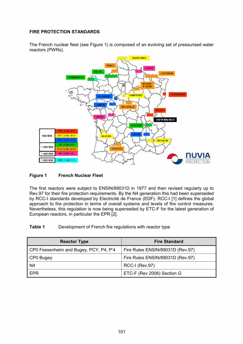
FIRE PROTECTION STANDARDS The French nuclear fleet (see Figure 1) is composed of an evolving set of pressurised water reactors (PWRs).
Figure 1 French Nuclear Fleet The first reactors were subject to ENSIN/89031D in 1977 and then revised regularly up to Rev.97 for their fire protection requirements. By the N4 generation this had been superseded by RCC-I standards developed by Electricité de France (EDF). RCC-I [1] defines the global approach to fire protection in terms of overall systems and levels of fire control measures. Nevertheless, this regulation is now being superseded by ETC-F for the latest generation of European reactors, in particular the EPR [2]. Table 1 Development of French fire regulations with reactor type
Reactor Type Fire Standard
CP0 Fessenheim and Bugey, PCY, P4, P’4 Fire Rules ENSIN/89031D (Rev.97)
CP0 Bugey Fire Rules ENSIN/89031D (Rev.97)
N4 RCC-I (Rev.97)
EPR ETC-F (Rev 2006) Section G
101

RCC-I DESIGN, CONSTRUCTION AND INSTALLATION RULES FOR FIRE PROTECTION RCC-I [1] describes the fundamental approach to fire protection. Physical Protection Systems The physical protection systems are classified into three levels: Level 1: fire prevention – design of plants and operations to minimise the risk of fire by:
minimising the use of combustible materials, for example, by implementation of fire safety analysis,
using as much as possible equipment such as fire doors and fire retardant cables. Level 2: fire containment – use of physical separation, fire retardant and passive fire pro-
tection to minimise the impact of a fire on the plant. In particular, safety critical systems must be designed so that redundancy components cannot be affected simultaneously by the outbreak of a fire. This involves fire segregation of building layouts and use of fire barriers. The heat release in each defined area must be less than 400 MJ/m2.
Level 3: fire control – gain control over the fire as soon as possible. This will involve the use of fire detection, extinguishing and smoke control systems.
Vulnerability Analysis Vulnerability analysis is used to assess the possibility of common mode failures (CMF). For example by defining the redundancy items involved in safety related systems, the relia-bility of support systems, the probability of electrical failures and the use of mitigation sys-tems. Operator Procedures Procedures need to be in place to define the actions required in case of outbreak or sus-pected outbreak of a fire in the plant. This includes the procedures for the periodic inspection and testing of all the fire prevention systems. ETC-F EUROPEAN TECHNICAL CODE – FIRE PROTECTION The Evolutionary Pressurised Water Reactor (EPR) project was started in 1989 through a joint venture between Framatome and Siemens (Nuclear Power International). The French and German utilities also participated in the evolution of the reactor as well as the involve-ment of the safety authorities (ASN in France and BMU in Germany). One objective was to harmonize and further develop the outstanding safety standards in France and Germany. An organization was set up to develop common codes from the French design and construction rules (RCC) and the German KTA safety standards and DIN standards related to the EPR design. This led to the establishment of the EPR Technical Codes (ETC). As part of this de-velopment it was agreed to establish a new fire protection code, the ETC-F [2]. ETC-F follows the principles of RCC-I for the definitions of defence levels and analysis.
102

THE USE OF PASSIVE FIRE PROTECTION TO MEET ETC-F REQUIREMENTS We will now focus on the evolution of passive fire protection induced by the new rules set by ETC-F. Fire Requirements Fire specific requirements have changed in two directions with implementation of ETC-F. The first change was the application of the decree “Arrêté feu du 22 Mars 2004” [3] related to fire resistance. Fire resistance is the capacity of building materials to withstand fire for a cer-tain period of time. It refers to European standards.
Figure 2 French regulation versus European regulation
Figure 3 European Fire Standards based on EN 1363-1 [4]
EN 1363 -1General requirements
EN 1363 -2Alternative & additional procedures
ENV 1363 -3Verification of furnace performance
EN 1364Non-loadbearing
elements
EN 1365Loadbearing
elements
EN 1366Service installations
EN 1634Fire doors& shutters
ENV 13381Contribution toFire Resistance
EN 1363 -1General requirements
EN 1363 -2Alternative & additional procedures
ENV 1363 -3Verification of furnace performance
EN 1364Non-loadbearing
elements
EN 1365Loadbearing
elements
EN 1366Service installations
EN 1634Fire doors& shutters
ENV 13381Contribution toFire Resistance
103
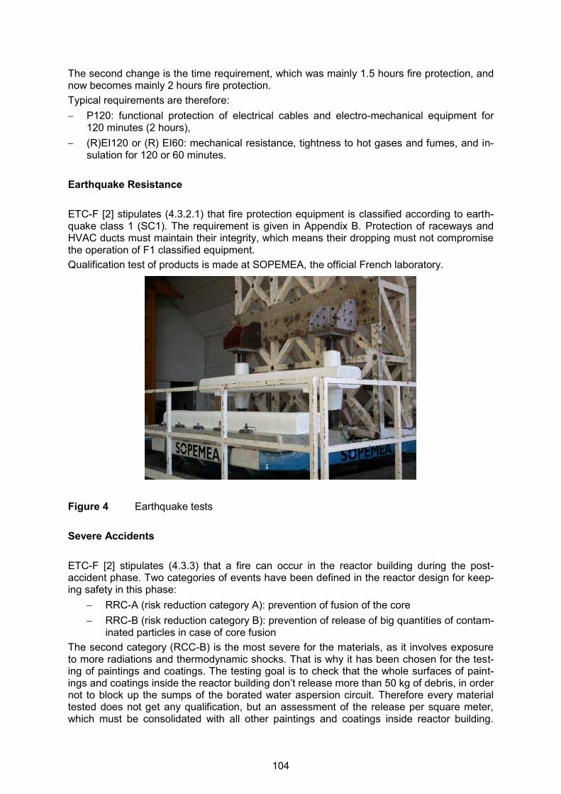
The second change is the time requirement, which was mainly 1.5 hours fire protection, and now becomes mainly 2 hours fire protection. Typical requirements are therefore: P120: functional protection of electrical cables and electro-mechanical equipment for
120 minutes (2 hours), (R)EI120 or (R) EI60: mechanical resistance, tightness to hot gases and fumes, and in-
sulation for 120 or 60 minutes. Earthquake Resistance ETC-F [2] stipulates (4.3.2.1) that fire protection equipment is classified according to earth-quake class 1 (SC1). The requirement is given in Appendix B. Protection of raceways and HVAC ducts must maintain their integrity, which means their dropping must not compromise the operation of F1 classified equipment. Qualification test of products is made at SOPEMEA, the official French laboratory.
Figure 4 Earthquake tests Severe Accidents ETC-F [2] stipulates (4.3.3) that a fire can occur in the reactor building during the post-accident phase. Two categories of events have been defined in the reactor design for keep-ing safety in this phase:
RRC-A (risk reduction category A): prevention of fusion of the core RRC-B (risk reduction category B): prevention of release of big quantities of contam-
inated particles in case of core fusion The second category (RCC-B) is the most severe for the materials, as it involves exposure to more radiations and thermodynamic shocks. That is why it has been chosen for the test-ing of paintings and coatings. The testing goal is to check that the whole surfaces of paint-ings and coatings inside the reactor building don’t release more than 50 kg of debris, in order not to block up the sumps of the borated water aspersion circuit. Therefore every material tested does not get any qualification, but an assessment of the release per square meter, which must be consolidated with all other paintings and coatings inside reactor building.
104
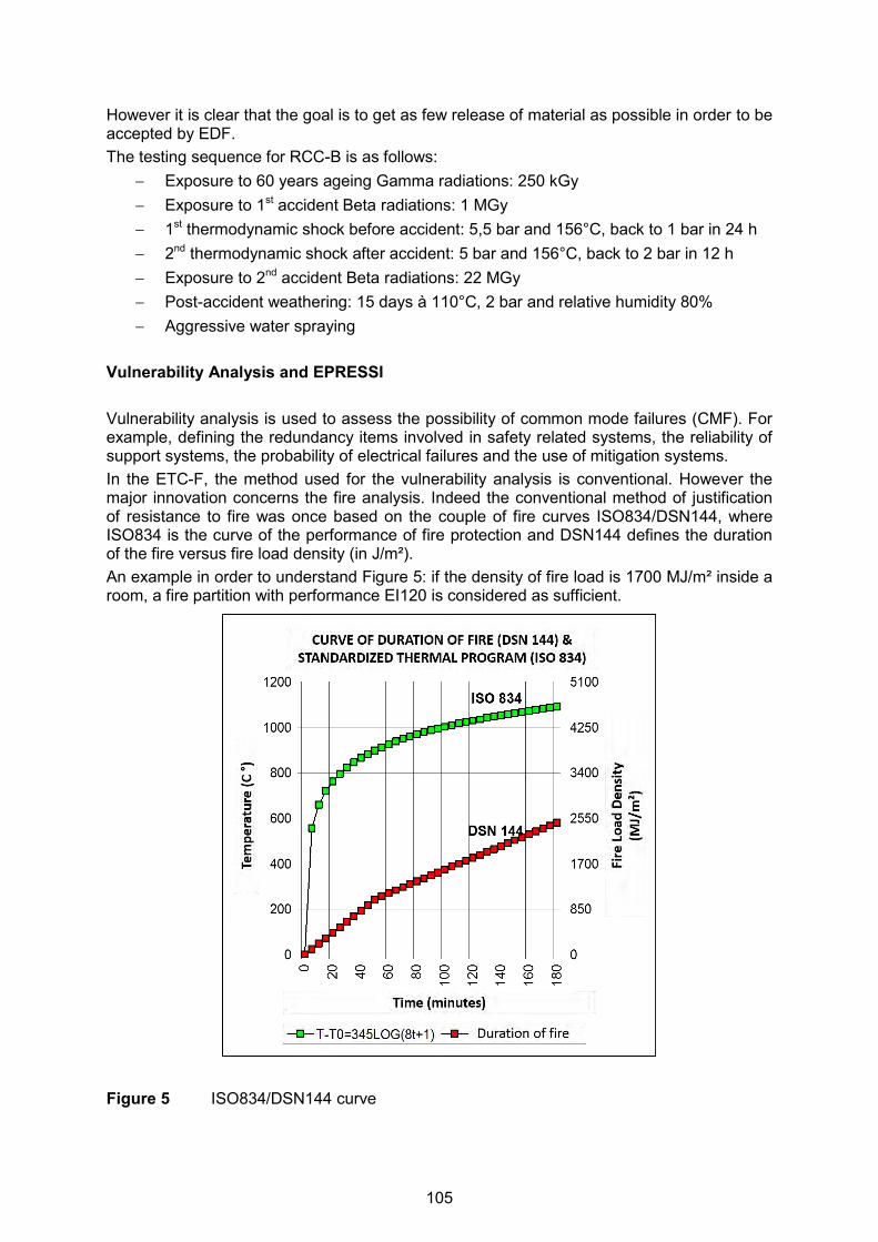
However it is clear that the goal is to get as few release of material as possible in order to be accepted by EDF. The testing sequence for RCC-B is as follows:
Exposure to 60 years ageing Gamma radiations: 250 kGy Exposure to 1st accident Beta radiations: 1 MGy 1st thermodynamic shock before accident: 5,5 bar and 156°C, back to 1 bar in 24 h 2nd thermodynamic shock after accident: 5 bar and 156°C, back to 2 bar in 12 h Exposure to 2nd accident Beta radiations: 22 MGy Post-accident weathering: 15 days à 110°C, 2 bar and relative humidity 80% Aggressive water spraying
Vulnerability Analysis and EPRESSI Vulnerability analysis is used to assess the possibility of common mode failures (CMF). For example, defining the redundancy items involved in safety related systems, the reliability of support systems, the probability of electrical failures and the use of mitigation systems. In the ETC-F, the method used for the vulnerability analysis is conventional. However the major innovation concerns the fire analysis. Indeed the conventional method of justification of resistance to fire was once based on the couple of fire curves ISO834/DSN144, where ISO834 is the curve of the performance of fire protection and DSN144 defines the duration of the fire versus fire load density (in J/m²). An example in order to understand Figure 5: if the density of fire load is 1700 MJ/m² inside a room, a fire partition with performance EI120 is considered as sufficient.
Figure 5 ISO834/DSN144 curve
105
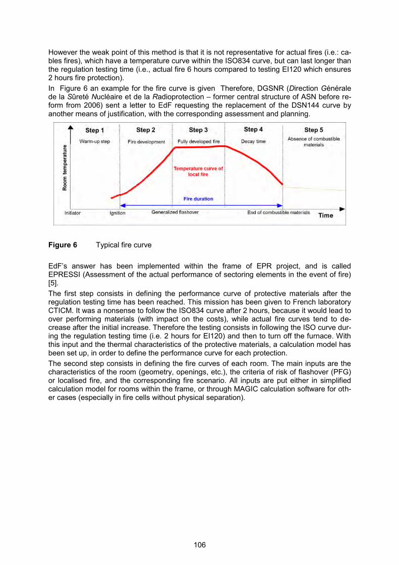
However the weak point of this method is that it is not representative for actual fires (i.e.: ca-bles fires), which have a temperature curve within the ISO834 curve, but can last longer than the regulation testing time (i.e., actual fire 6 hours compared to testing EI120 which ensures 2 hours fire protection). In Figure 6 an example for the fire curve is given Therefore, DGSNR (Direction Générale de la Sûreté Nucléaire et de la Radioprotection – former central structure of ASN before re-form from 2006) sent a letter to EdF requesting the replacement of the DSN144 curve by another means of justification, with the corresponding assessment and planning.
Figure 6 Typical fire curve EdF’s answer has been implemented within the frame of EPR project, and is called EPRESSI (Assessment of the actual performance of sectoring elements in the event of fire) [5]. The first step consists in defining the performance curve of protective materials after the regulation testing time has been reached. This mission has been given to French laboratory CTICM. It was a nonsense to follow the ISO834 curve after 2 hours, because it would lead to over performing materials (with impact on the costs), while actual fire curves tend to de-crease after the initial increase. Therefore the testing consists in following the ISO curve dur-ing the regulation testing time (i.e. 2 hours for EI120) and then to turn off the furnace. With this input and the thermal characteristics of the protective materials, a calculation model has been set up, in order to define the performance curve for each protection. The second step consists in defining the fire curves of each room. The main inputs are the characteristics of the room (geometry, openings, etc.), the criteria of risk of flashover (PFG) or localised fire, and the corresponding fire scenario. All inputs are put either in simplified calculation model for rooms within the frame, or through MAGIC calculation software for oth-er cases (especially in fire cells without physical separation).
106

Figure 7 Performance / actual room fire curves Fire Prevention and Fire Load Suppression (FLS) It was shown above that one input which leads to a fire scenario is that the room meets ei-ther the localised fire risk (PFL) or flashover risk (PFG) criteria, which are (non-exhaustive extract from ETC-F): PFG if the room with areas below 30 m² meets at minimum one of the following criteria: 1. The presence of more than 3 superimposed horizontal bearings of more than 3 m long 2. The presence of more than 3 superimposed horizontal bearings of more than 3 m long,
the highest of which is less than 50 cm from the ceiling 3. The presence of fuel with rapid combustion kinetics (unless special justification is given) PFL, if the room is not PFG but meets at minimum one of the following criteria: 1. Raceway and local installation: the presence of 2 x 200 mm horizontal secondary race-
ways, separated by a distance below 1 m and routed in parallel over a distance above 1m or the presence of a 200 mm vertical secondary raceway over a height of 2 m;
2. Electrical cabinets and switch boxes: electrical cabinets and switch boxes which have openings or forced convection are considered to be the potential causes of localised fires.
107
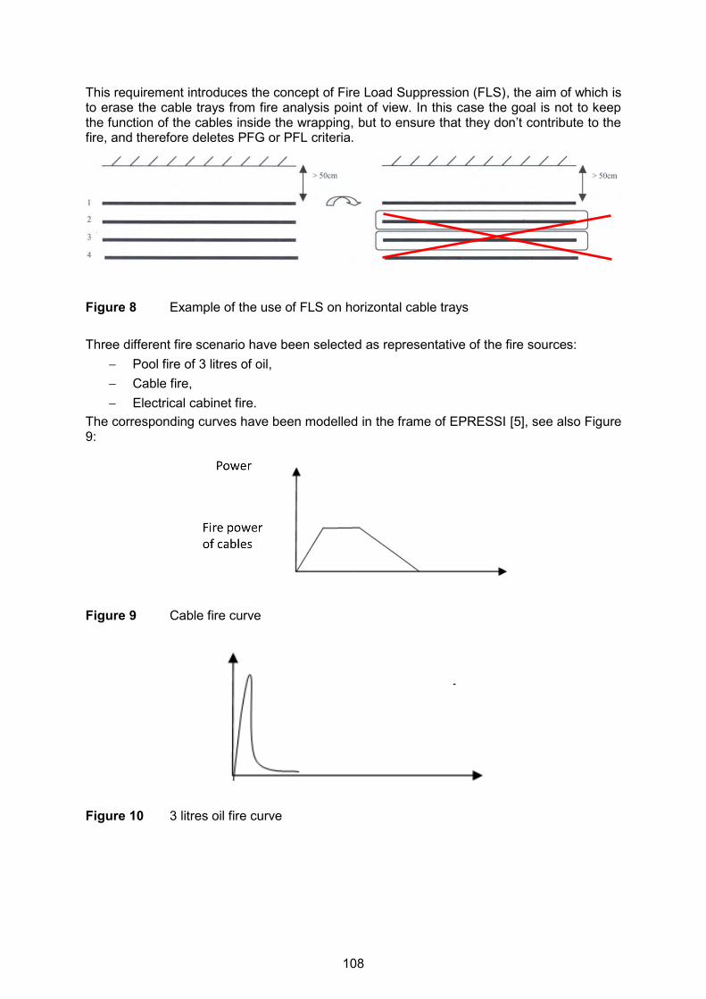
This requirement introduces the concept of Fire Load Suppression (FLS), the aim of which is to erase the cable trays from fire analysis point of view. In this case the goal is not to keep the function of the cables inside the wrapping, but to ensure that they don’t contribute to the fire, and therefore deletes PFG or PFL criteria.
Figure 8 Example of the use of FLS on horizontal cable trays Three different fire scenario have been selected as representative of the fire sources:
Pool fire of 3 litres of oil, Cable fire, Electrical cabinet fire.
The corresponding curves have been modelled in the frame of EPRESSI [5], see also Figure 9:
Figure 9 Cable fire curve
Figure 10 3 litres oil fire curve
108
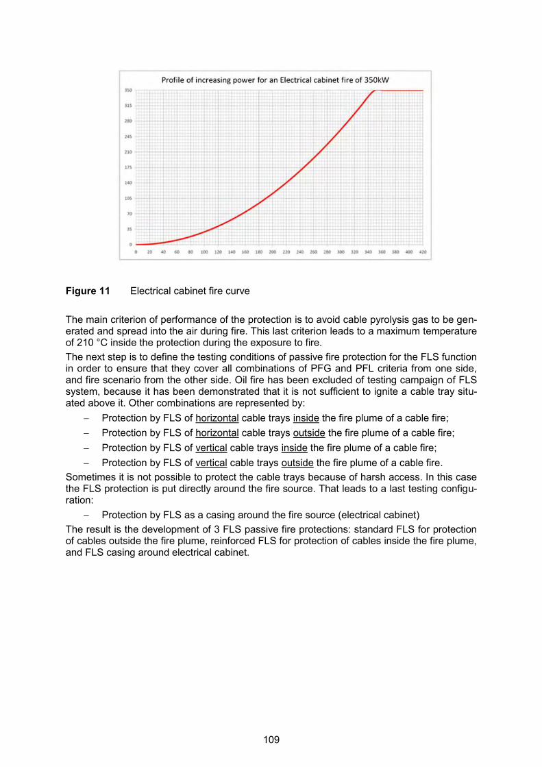
Figure 11 Electrical cabinet fire curve The main criterion of performance of the protection is to avoid cable pyrolysis gas to be gen-erated and spread into the air during fire. This last criterion leads to a maximum temperature of 210 °C inside the protection during the exposure to fire. The next step is to define the testing conditions of passive fire protection for the FLS function in order to ensure that they cover all combinations of PFG and PFL criteria from one side, and fire scenario from the other side. Oil fire has been excluded of testing campaign of FLS system, because it has been demonstrated that it is not sufficient to ignite a cable tray situ-ated above it. Other combinations are represented by:
Protection by FLS of horizontal cable trays inside the fire plume of a cable fire; Protection by FLS of horizontal cable trays outside the fire plume of a cable fire; Protection by FLS of vertical cable trays inside the fire plume of a cable fire; Protection by FLS of vertical cable trays outside the fire plume of a cable fire.
Sometimes it is not possible to protect the cable trays because of harsh access. In this case the FLS protection is put directly around the fire source. That leads to a last testing configu-ration:
Protection by FLS as a casing around the fire source (electrical cabinet) The result is the development of 3 FLS passive fire protections: standard FLS for protection of cables outside the fire plume, reinforced FLS for protection of cables inside the fire plume, and FLS casing around electrical cabinet.
109

Figure 12 Standard FLS (vertical cable tray outside fire plume)
Figure 13 Reinforced FLS (horizontal cable tray inside fire plume)
110

Figure 14 Casing around electrical cabinet as potential fire source Fire Containment The general concept of fire compartments is implemented in the design of all buildings asso-ciated with the reactor systems. These compartments must be completely sealed with fire resistant sealing products for any opening or penetrations. In addition, the concept of fire cells can be used under special circumstances. A fire cell uses separation and protective structures to delay the spread of fire. ETC-F [2] requires each building to be subdivided into fire compartments with the following characteristics: as
Redundant safety systems must be separated. Areas with potential fire hazards must be isolated. Protected escape routes for personnel must be provided.
The boundaries between the fire compartments need to meet the requirements as given in the following Table 2.
111

Table 2 Certification required by ETC-F for fire containment elements
SFC SFE SFS SFA* SR**
Structure R120 R60 R120 R60 R60
Loadbearing walls REI120 REI120 REI120 REI60 REI60
Non-loadbearing walls
EI120 EI120 EI120 EI60 EI60
Doors EI1120SmC5 EI160SmC5 EI1120SmC5 EI160SmC5 EI160SmC5 Penetrations EI120 EI60 EI120 EI60 EI60
Fire dampers EI120S EI60S EI120S EI60S EI60S
Joints EI120 EI60 EI120 EI60 EI60
Functional enclosures - cases
P120 P120 P120 N/A N/A
* Minimum classification. The partitions of an SFA take the classification of the adjacent compart-ments, if this classification is higher.
** Minimum classification. The criteria may be more severe depending on the characteristics of the reference fire of the room or compartment.
Materials and products supplied to seal the compartments must meet these requirements as well as other structural and operational design considerations. Passive fire protection prod-ucts can be manufactured in a wide range of forms and can be customised to meet specific fire resistant requirements. In addition the installation methods have to be designed to en-sure that the fire properties of the final system meet the overall requirements.
a)
b)
c)
Figure 15 a) to c): Protection EI120 of electrical penetrations using silicone based prod-ucts
112
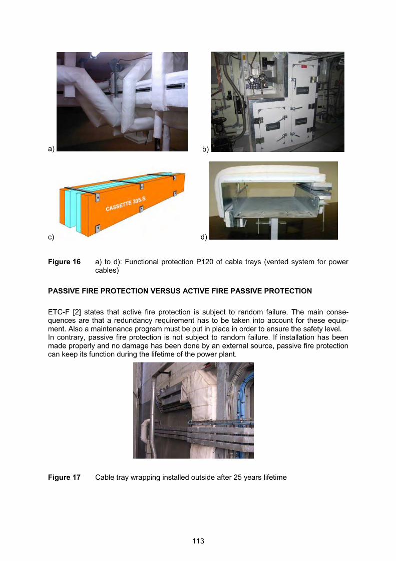
a) b)
c) d)
Figure 16 a) to d): Functional protection P120 of cable trays (vented system for power
cables) PASSIVE FIRE PROTECTION VERSUS ACTIVE FIRE PASSIVE PROTECTION ETC-F [2] states that active fire protection is subject to random failure. The main conse-quences are that a redundancy requirement has to be taken into account for these equip-ment. Also a maintenance program must be put in place in order to ensure the safety level. In contrary, passive fire protection is not subject to random failure. If installation has been made properly and no damage has been done by an external source, passive fire protection can keep its function during the lifetime of the power plant.
Figure 17 Cable tray wrapping installed outside after 25 years lifetime
113

CONCLUSIONS ETC-F gives a major role to fire protection, firstly by involving it into fire prevention (Fire Load Suppression), and secondly by giving priority to physical separation of fire zones into fire containment. It also applies the new rules of the French safety authorities (ASN), which require more pre-cision in the justification of fire resistance of actual configurations compared to theory (EPRESSI method). The consequence is that manufacturers and installers of passive fire protection cannot be considered as only sub-suppliers, but as partners which must be in-volved very soon in the development of the nuclear power plants fire protection. These man-ufacturers and installers must also get a great knowledge of the rules of fire protection, and have to develop skills in fire analysis in order to offer and justify their best solutions for each particular case. REFERENCES [1] RCC-I, Design, Construction and Installation Rules for Fire Protection Codes, Edition
1997. [2] ETC-F, EPR Technical Codes for Fire Protection, Edition 2013,
http://www.afcen.com/en/publications/etc-f. [3] Arrêté feu du 22 Mars 2004, March 2004, (in French only),
http://www.legifrance.gouv.fr/affichTexte.do?cidTexte=JORFTEXT000000249854. [4] EN 1363-1 Fire resistance tests - Part 1: General requirements, Edition 2013.EDF [5] Electricité de France, EDF-SA, Service Etudes et Project Thermiques et Nucléaires
(SEPTEN), Principle of the EPRESSI Method, ENGSIN070401, Edition 2008.
114
© 2013 Organisation for Economic Co-operation and Development
Recent Enhancements of the OECD FIRE Database
Marin a Röwekamp (GRS)Matti Lehto (STUK)
Wolfgang and Andreas Werner (SAC)
14th International Post-Conference Seminar on“FIRE SAFETY IN NUCLEAR POWER PLANTS
AND INSTALLATIONS”
© 2013 Organisation for Economic Co-operation and Development
2
Introduction - 1
� OECD FIRE (Fire Incidents Records Exchange) Database is 1 of 5 databases collecting events from NPP operation
� In the late 1990s it became evident that IRS and INES are not suitable for specific analysis and use in fire risk assessment
� Purposes of the OECD FIRE Database Project: • Provide a platform for multiple countries to collaborate and
exchange fire data and thereby to enhance the knowledge of fire phenomena
• Improve the quality of risk assessment requiring fire related data and knowledge
IRS: Incident reporting systemINES: International Nuclear and Radiological Event Scale
14th International Post-SMiRT Seminar on "Fire Safety in Nuclear Power Plants and Installations"
115
© 2013 Organisation for Economic Co-operation and Development
3
Introduction - 2
� OECD FIRE Database collects fire incidents experience from nuclear power plants by international exchange
• in an appropriate format
• in a quality assured and consistent database
� Well-defined Operating Procedures (OP) ensure that the information from the Database is anonymous
� Access to the Database is possible only to individuals in organizations from member countries providing data signing a confidentiality agreement
� Coding Guidelines (CG) and Quality Assurance (QA) Manual are continuously enhanced (by users´ feedback) and extended for ensuring data validity and data quality and complete the Project documentation
14th International Post-SMiRT Seminar on "Fire Safety in Nuclear Power Plants and Installations"
© 2013 Organisation for Economic Co-operation and Development
4
Introduction - 3
� FIRE Database, version 2014:01 covers 448 fire event records up to the end of 2014
� Database represents nearly 8000 years of NPP experience from all plant operational states (POS)
� Project is meanwhile in Phase 4 (2014 – 2015) with 12 member states(CAN, CZE, ESP, FIN, FRA, GER, JAP, KOR, NED, SWD, SWI, USA)
� FIRE Database use:• Identify all types of events and scenarios for inclusion in PSA
models ensuring that all mechanisms are accounted for• Support Fire PSA by real data from NPP operating experience,
in particular to evaluate fire occurrence frequencies• Compare national fire event data from member states with the
accumulated international data14th International Post-SMiRT Seminar on "Fire Safety
in Nuclear Power Plants and Installations"
116

© 2013 Organisation for Economic Co-operation and Development
5
OECD FIRE Database Search Possibilities - 1
Entry Menu Screenshot
14th International Post-SMiRT Seminar on "Fire Safety in Nuclear Power Plants and Installations"
© 2013 Organisation for Economic Co-operation and Development
6
OECD FIRE Database Search Possibilities - 2
� 'Search fire events' function: either whole Database or already existing subsets generated by earlier queries as basis for new queries
� Different types of fields permit a selection of:
• One attribute from a pull-down menu
• Multiple attributes connected by logical 'OR' within coded fields 'Operation mode', 'Country' and 'Reactor type'
• Multiple attributes connected by logical 'AND’ or 'OR' or 'EXCLUDE'
• Coding permits text string searches in all comments fields
� All fields are connected by logical 'AND'
14th International Post-SMiRT Seminar on "Fire Safety in Nuclear Power Plants and Installations"
117

© 2013 Organisation for Economic Co-operation and Development
7
OECD FIRE Database Search Possibilities - 3
� Result of any search can be stored as subset
� Different analysis modes can be chosen regarding 'Evaluate' function:
• Single selection fields and mutually exclusive multiple selection fields (reactor type, country, operation mode)
• Pairs of single selection fields (cross tables)
• Fields in which multiple attributes can be selected
14th International Post-SMiRT Seminar on "Fire Safety in Nuclear Power Plants and Installations"
© 2013 Organisation for Economic Co-operation and Development
8
OECD FIRE Database Search Possibilities - 4
Result of exemplary query – evaluation of all ignition mechanisms
14th International Post-SMiRT Seminar on "Fire Safety in Nuclear Power Plants and Installations"
118

© 2013 Organisation for Economic Co-operation and Development
9
OECD FIRE Database Search Possibilities - 5
Screenshot of the input format for pairs of single selection fields
14th International Post-SMiRT Seminar on "Fire Safety in Nuclear Power Plants and Installations"
© 2013 Organisation for Economic Co-operation and Development
10
OECD FIRE Database Search Possibilities - 6
Screenshot of search by ‘observation times' func tion
14th International Post-SMiRT Seminar on "Fire Safety in Nuclear Power Plants and Installations"
119

© 2013 Organisation for Economic Co-operation and Development
11
Actual Application s of the OECD FIRE Database: Compartment Specifi c Fire Frequencies - 1
Example: Selected PWR buildings, power operation, countries reporting all events
Compart-menttype
Building
Proce ss rooms
Rooms for electrical control
equipment (incl. MCR)
Switchgear rooms
Turbine Building
2.5 E-04/ry 1.1 E-04/ry no event
Auxiliary Building
1.2 E-04/ry 2.8 E-04/ry 2.1 E-04/ry
Reactor Building
8.6 E-05/ry no event no event
Electrical Building
5.3 E-05/ry 3.2 E-04/ry 1.0 E-03/ry
Remark: Experience covers 985 ry.
14th International Post-SMiRT Seminar on "Fire Safety in Nuclear Power Plants and Installations"
© 2013 Organisation for Economic Co-operation and Development
12
Actual Application s of the OECD FIRE Database: Compartment Specific Fire Frequencies - 2
Example: Selected PWR buildings, low power & shutdown, countries reporti ng all events
Compart-menttype
Building
Proce ss rooms
Rooms for electrical control
equipment (incl. MCR)
Switchgear rooms
Turbine Building
2.3 E-03/ry no event no event
Auxiliary Building
6.0 E-04/ry 2.8 E-03/ry no event
Reactor Building
8.6 E-04/ry no event no event
Electrical Building
no event no event 8.3 E-03/ry
Remark: Experience covers 100 ry.
14th International Post-SMiRT Seminar on "Fire Safety in Nuclear Power Plants and Installations"
120
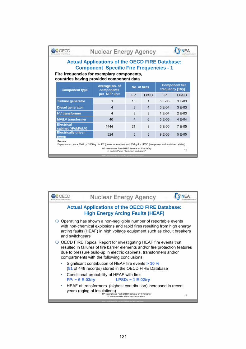
© 2013 Organisation for Economic Co-operation and Development
13
Actual Application s of the OECD FIRE Database: Component Specific Fire Frequencies - 1
Fire frequencies for exemplary components, countries having pro vided component data
Component typeAverage no. of compo nentsper NPP unit
No. of firesComponent fire
frequency [1/ry]
FP LPSD FP LP/SD
Turbine generator 1 10 1 5 E-03 3 E-03
Diesel generator 4 3 4 5 E-04 3 E-03
HV transformer 4 8 3 1 E-04 2 E-03
MV/LV transformer 40 4 6 5 E-05 4 E-04Electrical cabinet (HV/MV/LV)
1444 21 3 6 E-05 7 E-05
Electrically driven pump
324 5 5 9 E-06 5 E-05
Remark: Experience covers 2142 ry, 1806 ry for FP (power operation), and 336 ry for LPSD (low power and shutdown states)
14th International Post-SMiRT Seminar on "Fire Safety in Nuclear Power Plants and Installations"
© 2013 Organisation for Economic Co-operation and Development
14
Actual Application s of the OECD FIRE Database: High Energy Arcing F aults (HEAF)
� Operating has shown a non-negligible number of reportable events with non-chemical explosions and rapid fires resulting from high energy arcing faults (HEAF) in high voltage equipment such as circuit breakers and switchgears
� OECD FIRE Topical Report for investigating HEAF fire events that resulted in failures of fire barrier elements and/or fire protection features due to pressure build-up in electric cabinets, transformers and/or compartments with the following conclusions: • Significant contribution of HEAF fire events > 10 %
(51 of 448 records) stored in the OECD FIRE Database• Conditional probability of HEAF with fire:
FP: ~ 6 E-03/ry LPSD: ~ 1 E-02/ry
• HEAF at transformers (highest contribution) increased in recent years (aging of insulations)
14th International Post-SMiRT Seminar on "Fire Safety in Nuclear Power Plants and Installations"
121
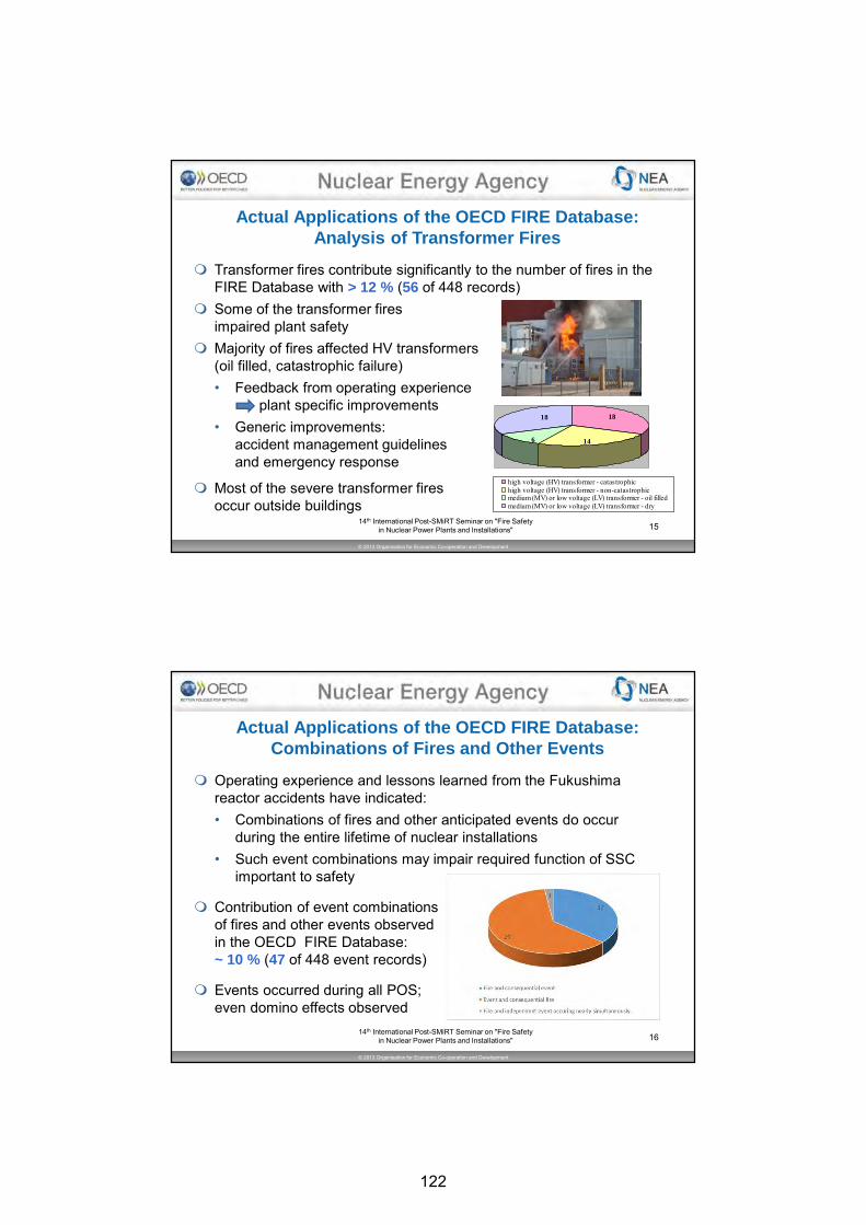
© 2013 Organisation for Economic Co-operation and Development
15
Actual Application s of the OECD FIRE Database: Analysis of Transfo rmer Fires
� Transformer fires contribute significantly to the number of fires in the FIRE Database with > 12 % (56 of 448 records)
� Some of the transformer fires impaired plant safety
� Majority of fires affected HV transformers(oil filled, catastrophic failure)• Feedback from operating experience
plant specific improvements• Generic improvements:
accident management guidelines and emergency response
� Most of the severe transformer fires occur outside buildings
18
6 14
18
high voltage (HV) transformer - catastrophichigh voltage (HV) transformer - non-catastrophicmedium (MV) or low voltage (LV) transformer - oil filledmedium (MV) or low voltage (LV) transformer - dry
14th International Post-SMiRT Seminar on "Fire Safety in Nuclear Power Plants and Installations"
© 2013 Organisation for Economic Co-operation and Development
16
Actual Application s of the OECD FIRE Database: Combinations of Fire s and Other Events
� Operating experience and lessons learned from the Fukushima reactor accidents have indicated:• Combinations of fires and other anticipated events do occur
during the entire lifetime of nuclear installations• Such event combinations may impair required function of SSC
important to safety
� Contribution of event combinationsof fires and other events observed in the OECD FIRE Database:~ 10 % (47 of 448 event records)
� Events occurred during all POS; even domino effects observed
14th International Post-SMiRT Seminar on "Fire Safety in Nuclear Power Plants and Installations"
122

© 2013 Organisation for Economic Co-operation and Development
17
Database Challenge s
Data Consolidation
� Fire Events Database (FEDB) by U.S. NRC and EPRI issued in 2013 capturing fire event history up through 2009 for ~ 2000 fire events at varying severity levels
� FEDB is intended to be merged in OECD FIRE � Challenges: • Aligning information into a usable format• Large portion of supplementary information in FEDB remains
proprietary plant information
� Advantage: significant increase of number of events in FIRE for PSA use
Challenges for Reducing Uncertainties
� Lack of knowledge on components or geometry of average compartment
� Clarification of overall amount of combustibles inside systems or component 14th International Post-SMiRT Seminar on "Fire Safety
in Nuclear Power Plants and Installations"
© 2013 Organisation for Economic Co-operation and Development
18
Conclusions
� OECD FIRE is a valuable tool for facilitating use of NPP fire experience and applicable as a source of generic event data for deterministic fire safety analysis as well as probabilistic fire risk assessment (Fire PRA)
� Database structure has been recently improved and extended facilitating statistical analysis
� Different applications make use of enhanced possibilities
� Various queries based e.g. on reactor type, POS, pre-selection of countries to be considered (e.g. regarding reporting criteria and thresholds), as well as trend analyses are possible
� Compartment specific frequencies can be determined, while estimation of component related frequencies remains a challenge
14th International Post-SMiRT Seminar on "Fire Safety in Nuclear Power Plants and Installations"
123

© 2013 Organisation for Economic Co-operation and Development
19
Outlook
� OECD FIRE Phase 5 is intended to start in 2016 (3 years duration)
� Still limited statistical Database capabilities have to be and will be further extended
� Application already started: generic fire event trees for PRA purposes
� Potential issues for further Topical Reports
• Apparent causes and direct reasons of fire events
• In-depth analysis of recent transformer fires
• Control room abandonment / reduced habitability
14th International Post-SMiRT Seminar on "Fire Safety in Nuclear Power Plants and Installations"
© 2013 Organisation for Economic Co-operation and Development
20
THANK YOU FOR YOUR ATTENTION!
For questions please contact:
Chair - Marina Röwekamp: [email protected] or
Vice Chair - Matti Lehto: [email protected] or
Operating Agent - SAC: [email protected] or
NEA Secretariat - Neil Blundell: [email protected]
124
23rdInternational Conference on Structural Mechanics in Reactor Technology (SMiRT 23) - 14h
International Post-Conference Seminar on “FIRE SAFETY IN NUCLEAR POWER PLANTS AND INSTALLATIONS“
CHARACTERIZING THE THERMAL EFFECTS OF HIGH ENERGY ARC FAULTS
Anthony Putorti1, Nicholas B. Melly2, Scott Bareham1, Joseph Praydis Jr.1
1 National Institute of Standards and Technology (NIST), Gaithersburg, MD, USA
2 U.S. Nuclear Regulatory Commission (NRC), Washington, DC, USA ABSTRACT International and domestic operating experience involving High Energy Arc Faults (HEAF) in Nuclear Power Plant (NPP) electrical power systems have demonstrated the potential to cause extensive damage to electrical components and distribution systems along with dam-age to adjacent equipment and cables. An international study by the Committee on the Safe-ty of Nuclear Installations (CSNI) “OECD Fire Project – Topical Report No. 1: Analysis of High Energy Arcing Fault (HEAF) Fire Events” published June 25, 2013 [1], illustrates that HEAF events have the potential to be major risk contributors with significant safety conse-quences and substantial economic loss. In an effort to better understand and characterize the threats posed by HEAF related phenomena, an international project has been chartered; the Joint Analysis of Arc Faults (Joan of ARC) OECD International Testing Program for High Energy Arc Faults. One of the major challenges of this research is how to properly measure and characterize the risk and influence of these events. Methods are being developed to characterize relevant parameters such as; temperature, heat flux, and heat release rate of fires resulting from HEAF events. Full scale experiments are being performed at low (≤ 1000 V) and medium (≤ 35 kV) voltages in electrical components. This paper introduces the methods being developed to measure thermal effects and discusses preliminary results of full scale HEAF experiments. INTRODUCTION Switchgear, load centers, and bus bars/ducts (440 V and above) are subject to a unique fail-ure mode and, as a result, unique fire characteristics. In particular, these types of high-energy electrical devices are subject to high-energy arcing fault (HEAF). This fault mode leads to the rapid release of electrical energy in the form of heat, vaporized cop-per/aluminum, and mechanical force. Faults of this type are also commonly referred to as high energy, energetic, or explosive electrical equipment faults or fires. The energetic fault scenario typically consists of two distinct phases, each with its own dam-age characteristics. The first phase is characterized by a short, rapid release of electrical energy which may result in catastrophic failure of the electrical enclosure, ejection of hot pro-jectiles (from damaged electrical components or housing) and/or fire(s) involving the electri-cal device itself, as well as any external exposed combustibles, such as overhead exposed cable trays or nearby panels, that may be ignited during the energetic phase. The second phase, i.e., the ensuing fire(s) typically includes ignition of combustible material within the HEAF zone of influence (ZOI). The resulting fire may be due to the ejection of hot particles or piloted ignition of combustibles. HEAF events are of concern due to their potential to im-
This paper was prepared (in part) by employees of the United States Nuclear Regulatory Commission. It pre-
sents information related to NRC upcoming testing programs. NRC has neither approved nor disapproved its technical content. This paper does not establish an NRC technical position.
125

pact adjacent items important to safety and current limitations in characterizing the ZOI as defined in NUREG/CR-6850 [2]. Due to the potential safety significance of HEAF events, the OECD (Organization for Eco-nomic Co-operation and Development) Nuclear Energy Agency (NEA) Integrity and Ageing Working Group (IAGE) initiated a task on High Energy Arcing Events (HEAF) in 2009 to pro-vide an in-depth investigation on HEAF events in NEA member states [3]. The objective of this working group is to determine damage mechanisms, extent of areas affected, methods of protecting systems, structures and components (SSC) and possible calculation methods for modeling of HEAF events as applicable to fire protection in nuclear power plants (NPP). As part of this effort a testing program has been initiated to investigate the HEAF fire phe-nomena to inform future deterministic and probabilistic methods. This paper presents methods for measuring the heat release rates of ensuing fires and measuring the heat fluxes above and around the electrical enclosures during the HEAF ex-perimental program. Limited data are also presented. BACKGROUND In order to characterize the effects of the HEAF and ensuing fire on the surrounding equip-ment, various phenomena were chosen for characterization in the OECD program. These include enclosure pressure, enclosure surface temperature, heat release rate, and heat flux to target equipment. Electrical test parameters such as arc voltage, arc current, and arc du-ration were also measured during the experiments. Experiments were performed at KEMA-Powertest, located outside of Philadelphia, Pennsyl-vania, USA. The test facility includes a five-sided test cell approximately 8 m (26 ft) high, 7 m (24 ft) deep, and 9 m (29 ft) wide. The sixth side of the test cell includes a roll-up door that was fully open during the experiments. Bus bar connections for supplying low and medium voltage test current are located on opposite side walls of the test cell. KEMA-Powertest pro-vided measurements of electrical enclosure pressure, temperatures of slug calorimeters, electrical test parameters, videography, and high speed videography during the experiments. NIST provided measurements of heat release rate, heat flux, electrical enclosure surface temperature, thermal imaging, and multiple location videography during the experiments. The NPP equipment for the experiments was provided by OECD/NEA HEAF Project part-ners. Fourteen experiments have been performed to date using six electrical enclosures. Nominal test voltages ranged from 480 VAC to 7200 VAC, and nominal test currents ranged from 24 kA to 50 kA. All of the experiments conducted thus far have been performed with three phase power supplied in a delta configuration. The arcs were initiated in the enclo-sures by shorting across all three bus bar phases with a 2.6 mm diameter (10 AWG) tinned copper stranded wire prior to energizing the enclosures. EXPERIMENTAL METHODS Heat Release Rate In order to measure the heat release rate (HRR) of the ensuing fires caused by the HEAF events, a portable oxygen consumption heat release rate hood apparatus was deployed. The portable hood was first used in the HELEN-FIRE experiments to measure the heat re-lease rates of fires in control cabinets as described in NUREG/CR-7197 [4]. The portable apparatus was further developed and refined for use in the HEAF experiments. In the current form, the apparatus is a portable stand-alone system resistant to the effects of electromag-netic interference (EMI).
126
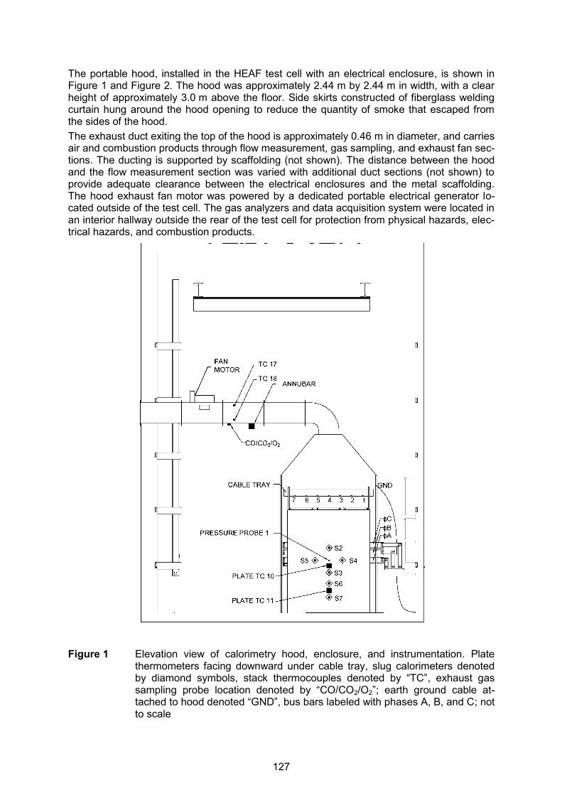
The portable hood, installed in the HEAF test cell with an electrical enclosure, is shown in Figure 1 and Figure 2. The hood was approximately 2.44 m by 2.44 m in width, with a clear height of approximately 3.0 m above the floor. Side skirts constructed of fiberglass welding curtain hung around the hood opening to reduce the quantity of smoke that escaped from the sides of the hood. The exhaust duct exiting the top of the hood is approximately 0.46 m in diameter, and carries air and combustion products through flow measurement, gas sampling, and exhaust fan sec-tions. The ducting is supported by scaffolding (not shown). The distance between the hood and the flow measurement section was varied with additional duct sections (not shown) to provide adequate clearance between the electrical enclosures and the metal scaffolding. The hood exhaust fan motor was powered by a dedicated portable electrical generator lo-cated outside of the test cell. The gas analyzers and data acquisition system were located in an interior hallway outside the rear of the test cell for protection from physical hazards, elec-trical hazards, and combustion products.
Figure 1 Elevation view of calorimetry hood, enclosure, and instrumentation. Plate
thermometers facing downward under cable tray, slug calorimeters denoted by diamond symbols, stack thermocouples denoted by “TC”, exhaust gas sampling probe location denoted by “CO/CO2/O2”; earth ground cable at-tached to hood denoted “GND”, bus bars labeled with phases A, B, and C; not to scale
127

Figure 2 Plan view of calorimetry hood, cabinet, and instrumentation; not to scale The heat release rates of the ensuing fire, �̇�(𝑡) (kW), was measured by oxygen consumption calorimetry, taking into account the measured concentrations of oxygen, carbon dioxide, and carbon monoxide in the exhaust gas [5], [6].
�̇�(𝑡) = [𝐸O2∅ − (𝐸CO − 𝐸O2
)1 − ∅
2(
𝑋CO
𝑋O2
)]�̇�e
1 + ∅(∝ −1)
𝑀O2
𝑀a(1 − 𝑋H2O,∞ )𝑋O2,∞ (1)
∅ =𝑋O2,∞(1 − 𝑋CO2
− 𝑋CO) − 𝑋O2(1 − 𝑋CO2,∞)
(1 − 𝑋O2− 𝑋CO2
− 𝑋CO)𝑋O2,∞
(2)
Here ∝ is the combustion expansion factor of 1.105, ∅ is the oxygen depletion factor, 𝐸O2 is
the net heat released for complete combustion of typical fuels, 13100 kJ/(kg O2), 𝐸CO is the
128

net heat released for complete combustion of CO, 17600 kJ/(kg O2), 𝑀a is the molecular weight of incoming air [g/mol], 𝑀O2
is the molecular weight of oxygen [g/mol], �̇�e is the ex-haust mass flow rate in the duct [kg/s], 𝑋O2,∞ is the initial oxygen volume fraction, 𝑋O2
is the measured oxygen volume fraction, 𝑋CO2,∞ is the initial carbon dioxide volume fraction, 𝑋CO2
is the measured carbon dioxide volume fraction, 𝑋CO is the measured carbon monoxide vol-ume fraction, and 𝑋H2O,∞ is the volume fraction of water vapor. Due to the large range of possible heat release rates, the apparatus design was biased to-ward resolution of the relatively small heat release rates expected from the ensuing fires. The heat release rate measurement range for the hood is approximately 10 kW to 3000 kW. The velocity of gases flowing through the hood duct was measured using an Annubar®1 av-eraging differential pressure element attached to a differential pressure transducer. The ge-ometry of the duct system differed from that specified by the manufacturer, resulting in less flow straightening and flow development. Due to the difference, calibration fires were used to determine the flow coefficient for the differential pressure element. Calibration fires were produced by a propane diffusion burner approximately 0.3 m by 0.3 m in size, providing fire heat release rates of approximately 35 kW and 50 kW. The propane burner heat release rates were calculated from the propane heat of combustion and the standard volume of propane provided to the burner as measured by a dry test flow meter corrected for temperature and pressure. For the oxygen consumption calculation of heat re-lease from the propane burner, the value of 𝐸O2
for propane is 12.78 MJ/(kg O2) [7]. The combined standard uncertainty, composed of Type A and Type B uncertainties, in the base heat release measurements was 10 %. The expanded uncertainty in the base heat release measurements was 20 %, with a coverage factor of 2, which corresponds to a confidence in-terval of 95 % [8], [9]. During the experiments, the effects of wind and smoke escaping the sides of the hood in-creased the level of measurement uncertainty. The one open side of the test cell allowed prevailing winds to drive combustion products away from the hood. Fire resistant fabric side skirts reduced the loss of smoke, but wind conditions resulted in the loss of significant quan-tities of smoke in some experiments. For each HEAF fire experiment, additional uncertainty contributions due to wind and losses of combustion products were estimated using observa-tions and video recordings. Temperature and Heat Flux One measure of the thermal environment during HEAF events and ensuing fires is the ther-mal heat flux imposed on materials surrounding the cabinets. There are various techniques available for measuring thermal heat flux, including water cooled transducers, slug calorime-ters, directional flame thermometers (DFT), and plate thermometers (PT). The use of these transducers for measuring the heat fluxes in HEAF events was explored in an NRC funded project [10]. For the OECD program HEAF experiments, the choice of transducers was revis-ited. The prime considerations for the experiments included a transducer that was sturdy and possessed a relatively short response time. One of the technologies frequently used in fire experiments is the water-cooled heat flux transducer (Schmidt-Boelter and Gardon Gauge types). There are two major drawbacks for their use in HEAF experiments, however. The first drawback is the presence of cooling water in the test cell, which presents logistical com-plications and safety hazards. The second drawback is related to the dynamic range of the 1 Certain commercial equipment, instruments, or materials are identified in this paper in order to specify the ex-
perimental procedure adequately. Such identification is not intended to imply recommendation or endorse-ment by the National Institute of Standards and Technology, nor is it intended to imply that the materials or equipment identified are necessarily the best available for the purpose.
129
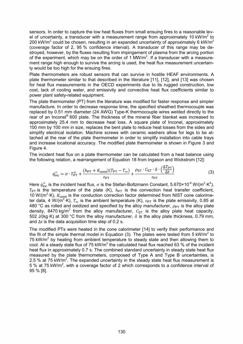
sensors. In order to capture the low heat fluxes from small ensuing fires to a reasonable lev-el of uncertainty, a transducer with a measurement range from approximately 10 kW/m2 to 200 kW/m2 could be chosen, resulting in an expanded uncertainty of approximately 6 kW/m2 (coverage factor of 2, 95 % confidence interval). A transducer of this range may be de-stroyed, however, by the fluxes resulting from impingement of plasma from the arcing portion of the experiment, which may be on the order of 1 MW/m2. If a transducer with a measure-ment range high enough to survive the arcing is used, the heat flux measurement uncertain-ty would be too high for the ensuing fires. Plate thermometers are robust sensors that can survive in hostile HEAF environments. A plate thermometer similar to that described in the literature [11], [12], and [13] was chosen for heat flux measurements in the OECD experiments due to its rugged construction, low cost, lack of cooling water, and emissivity and convective heat flux coefficients similar to power plant safety-related equipment. The plate thermometer (PT) from the literature was modified for faster response and simpler manufacture. In order to decrease response time, the specified sheathed thermocouple was replaced by 0.51 mm diameter (24 AWG) Type-K thermocouple wires welded directly to the rear of an Inconel® 600 plate. The thickness of the mineral fiber blanket was increased to approximately 25.4 mm to decrease heat loss. A square plate of Inconel, approximately 100 mm by 100 mm in size, replaces the bent plate to reduce heat losses from the sides and simplify electrical isolation. Machine screws with ceramic washers allow for legs to be at-tached at the rear of the plate thermometer in order to simplify installation into cable trays and increase locational accuracy. The modified plate thermometer is shown in Figure 3 and Figure 4. The incident heat flux on a plate thermometer can be calculated from a heat balance using the following relation, a rearrangement of Equation 18 from Ingason and Wickstrom [12]:
�̇�inc′′ = 𝜎 ∙ 𝑇PT
4 +(ℎPT + 𝐾cond)(𝑇PT − 𝑇∞)
휀PT+
𝜌ST ∙ 𝐶ST ∙ 𝛿 ∙ (∆𝑇PT
∆𝑡 )
휀PT (3)
Here �̇�inc′′ is the incident heat flux, 𝜎 is the Stefan-Boltzmann Constant, 5.670×10⁻⁸ W/(m2·K4),
𝑇PT is the temperature of the plate (K), ℎPT is the convection heat transfer coefficient, 10 W/(m2·K), 𝐾cond is the conduction correction factor determined from NIST cone calorime-ter data, 4 W/(m2·K), 𝑇∞ is the ambient temperature (K), 휀PT is the plate emissivity, 0.85 at 480 °C as rolled and oxidized and specified by the alloy manufacturer, 𝜌PT is the alloy plate density, 8470 kg/m3 from the alloy manufacturer, 𝐶ST is the alloy plate heat capacity, 502 J/(kg·K) at 300 °C from the alloy manufacturer, 𝛿 is the alloy plate thickness, 0.79 mm, and ∆𝑡 is the data acquisition time step of 0.2 s.
The modified PTs were heated in the cone calorimeter [14] to verify their performance and the fit of the simple thermal model in Equation (3). The plates were tested from 5 kW/m2 to 75 kW/m2 by heating from ambient temperature to steady state and then allowing them to cool. At a steady state flux of 75 kW/m2 the calculated heat flux reached 63 % of the incident heat flux in approximately 0.7 s. The combined standard uncertainty in steady state heat flux measured by the plate thermometers, composed of Type A and Type B uncertainties, is 2.5 % at 75 kW/m2. The expanded uncertainty in the steady state heat flux measurement is 5 % at 75 kW/m2, with a coverage factor of 2 which corresponds to a confidence interval of 95 % [8].
130

Figure 3 Exploded view of modified plate thermometer with cone calorimeter sample holder
Figure 4 Elevation view of modified plate thermometer on cone calorimeter sample holder
The heating of plate TCs in the cone calorimeter was modeled in one dimension with the Fire Dynamics Simulator (FDS) [15] to verify the assumptions and property data. Agreement to within 1 % was found between the temperatures measured during exposure in the cone calorimeter and the FDS predicted temperatures. Data from heating the plate thermometer at 75 kW/m2 in the cone calorimeter is included in the FDS validation library. Sensor Wiring and Data Acquisition Due to the voltages, currents, and electrical arcing that are present in and around the electri-cal equipment used in the HEAF experiments, electromagnetic interference (EMI) was pre-sent in the test facility. The electric and magnetic fields are capable of inducing voltages and currents in the sensor and data acquisition wiring. In order to reduce the effects of EMI, sev-eral strategies were employed in concert: shielding, isolation, signal conditioning, grounding, and electrical power conditioning. This multi-faceted approach greatly reduced or eliminated the effects of EMI on the measurement results. A conceptual drawing of the sensors, instrumentation, and data acquisition is shown in Fig-ure 5 and Figure 6. Figure 5 shows the wiring concept for a typical sensor, which includes plate thermometers and thermocouples. Figure 6 shows the wiring concept for the gas ana-lyzers and differential pressure transducer for measuring hood flow rates.
131
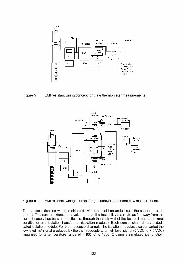
Figure 5 EMI resistant wiring concept for plate thermometer measurements
Figure 6 EMI resistant wiring concept for gas analysis and hood flow measurements The sensor extension wiring is shielded, with the shield grounded near the sensor to earth ground. The sensor extension traveled through the test cell, via a route as far away from the current supply bus bars as practicable, through the back wall of the test cell, and to a signal conditioner and isolation transformer (isolation module). Each sensor channel had a dedi-cated isolation module. For thermocouple channels, the isolation modules also converted the low level mV signal produced by the thermocouple to a high level signal (0 VDC to + 5 VDC) linearized for a temperature range of – 100 °C to 1350 °C using a simulated ice junction.
132

Non-thermocouple sensors were served by isolation modules that converted the input sig-nals to ± 1 VDC or ± 5 VDC output signals. The output of each isolation module was connected to one of two data acquisition modules, housed in a separate enclosure, via a shielded cable that was grounded to earth ground. The high level signals from the isolation modules were sampled by the data acquisition sys-tem (DAC), with the results communicated to a laptop computer (PC) via a USB cable. Data were recorded by the data acquisition system at a rate of 5 Hz. The main 115 VAC building power for the PC, data acquisition system, isolation modules, gas analyzers, and pressure transducer was supplied through signal conditioners, uninter-ruptible power supplies, and isolation transformers. The equipment chassis were grounded to earth. The heat release rate hood and duct support scaffolding were also grounded to earth. Grounding all of the equipment and cable shielding to the same earth ground prevent-ed ground loops. The cable trays above the electrical enclosures were electrically isolated from the enclosure and hood and ungrounded. The enclosures were supplied with 3 phase power in a delta configuration, with the enclosure ungrounded. RESULTS Heat Release Rate During the arcing phase of the HEAF experiments it was common for large quantities of rap-idly generated combustion products to escape the measurement hood to the atmosphere and therefore avoid measurement. In order to measure heat release rate during the arcing phase, a larger hood would be needed to capture the combustion products, the size of which is impractical for a portable system. To measure larger fires, the exhaust mass flow rate would need to be increased, which would decrease the ability to resolve small fires, and in-crease measurement uncertainty. The purpose of the portable apparatus is to measure the HRR of the secondary phase of the HEAF event, i.e., the ensuing fire. Oxygen consumption calorimetry for ordinary combustible materials such as flammable gas-es, flammable and combustible liquids, wood, and polymers utilizes a heat content of ap-proximately 13.1 MJ/kg of oxygen consumed [5]. During the HEAF portion of the experi-ments, a significant quantity of copper and aluminum were oxidized. The heat release rate calculations do not take into account the difference in EO2 between oxidation of metals and the combustion of ordinary combustibles. During the HEAF portion of the experiments, the average heat release rate [MW] was estimated from the arc energy [MJ] divided by the arc duration (s) instead of oxygen consumption calorimetry. The HEAF and ensuing fire from an experiment in a medium voltage cabinet are shown in Figure 7 and Figure 8. The nominal cabinet operating conditions were 7200 VAC and 24 kA with an arc of approximately 2554 ms in duration. The initial heat release from the cabinet due to the arc was not fully captured, but may be estimated as an average of approximately 28 MW from the arc energy expended during the arc. The heat release rate of the ensuing fire that occurred in the electrical enclosure following the HEAF event was recorded, with the primary fuel load consisting of the breaker housing. The maximum heat release rate of the ensuing fire was 165 kW. The expanded uncertainty in the heat release measurement is 25 %, with a coverage factor of 2, which corresponds to a confidence interval of 95 %.
133
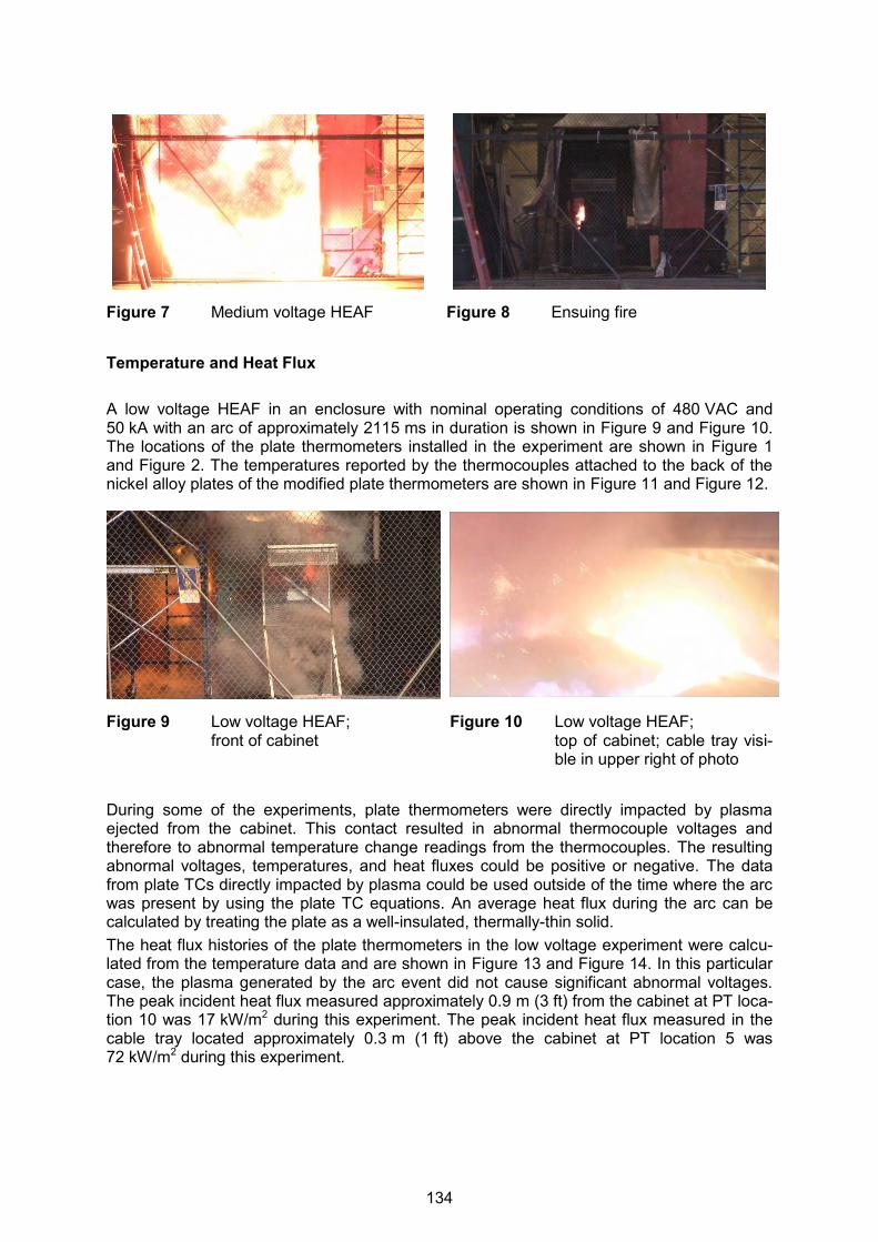
Figure 7 Medium voltage HEAF Figure 8 Ensuing fire Temperature and Heat Flux A low voltage HEAF in an enclosure with nominal operating conditions of 480 VAC and 50 kA with an arc of approximately 2115 ms in duration is shown in Figure 9 and Figure 10. The locations of the plate thermometers installed in the experiment are shown in Figure 1 and Figure 2. The temperatures reported by the thermocouples attached to the back of the nickel alloy plates of the modified plate thermometers are shown in Figure 11 and Figure 12.
Figure 9 Low voltage HEAF; front of cabinet
Figure 10 Low voltage HEAF; top of cabinet; cable tray visi-ble in upper right of photo
During some of the experiments, plate thermometers were directly impacted by plasma ejected from the cabinet. This contact resulted in abnormal thermocouple voltages and therefore to abnormal temperature change readings from the thermocouples. The resulting abnormal voltages, temperatures, and heat fluxes could be positive or negative. The data from plate TCs directly impacted by plasma could be used outside of the time where the arc was present by using the plate TC equations. An average heat flux during the arc can be calculated by treating the plate as a well-insulated, thermally-thin solid. The heat flux histories of the plate thermometers in the low voltage experiment were calcu-lated from the temperature data and are shown in Figure 13 and Figure 14. In this particular case, the plasma generated by the arc event did not cause significant abnormal voltages. The peak incident heat flux measured approximately 0.9 m (3 ft) from the cabinet at PT loca-tion 10 was 17 kW/m2 during this experiment. The peak incident heat flux measured in the cable tray located approximately 0.3 m (1 ft) above the cabinet at PT location 5 was 72 kW/m2 during this experiment.
134
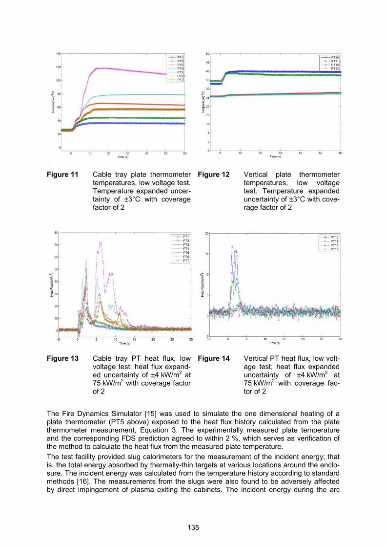
Figure 11 Cable tray plate thermometer temperatures, low voltage test. Temperature expanded uncer-tainty of ±3°C with coverage factor of 2
Figure 12 Vertical plate thermometer temperatures, low voltage test. Temperature expanded uncertainty of ±3°C with cove-rage factor of 2
Figure 13 Cable tray PT heat flux, low voltage test; heat flux expand-ed uncertainty of ±4 kW/m2 at 75 kW/m2 with coverage factor of 2
Figure 14 Vertical PT heat flux, low volt-age test; heat flux expanded uncertainty of ±4 kW/m2 at 75 kW/m2 with coverage fac-tor of 2
The Fire Dynamics Simulator [15] was used to simulate the one dimensional heating of a plate thermometer (PT5 above) exposed to the heat flux history calculated from the plate thermometer measurement, Equation 3. The experimentally measured plate temperature and the corresponding FDS prediction agreed to within 2 %, which serves as verification of the method to calculate the heat flux from the measured plate temperature. The test facility provided slug calorimeters for the measurement of the incident energy; that is, the total energy absorbed by thermally-thin targets at various locations around the enclo-sure. The incident energy was calculated from the temperature history according to standard methods [16]. The measurements from the slugs were also found to be adversely affected by direct impingement of plasma exiting the cabinets. The incident energy during the arc
135
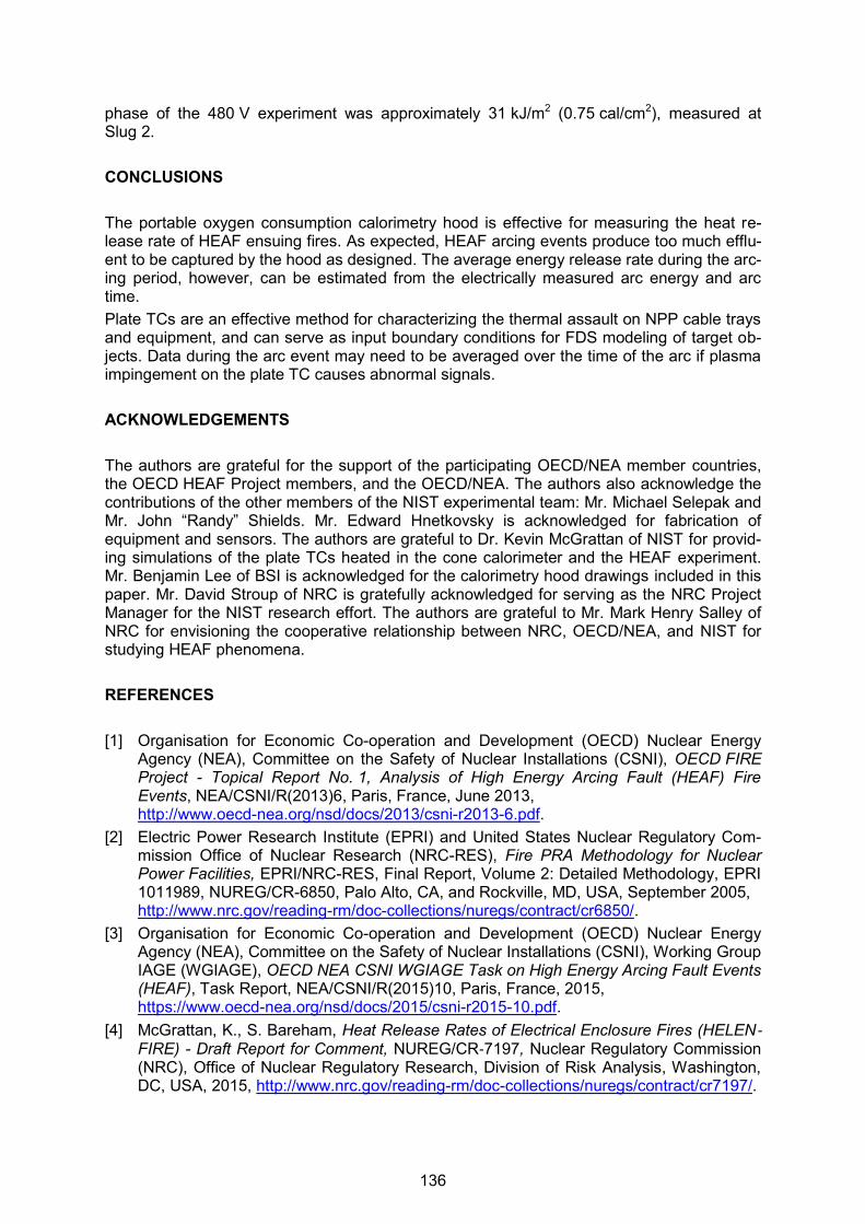
phase of the 480 V experiment was approximately 31 kJ/m2 (0.75 cal/cm2), measured at Slug 2. CONCLUSIONS The portable oxygen consumption calorimetry hood is effective for measuring the heat re-lease rate of HEAF ensuing fires. As expected, HEAF arcing events produce too much efflu-ent to be captured by the hood as designed. The average energy release rate during the arc-ing period, however, can be estimated from the electrically measured arc energy and arc time. Plate TCs are an effective method for characterizing the thermal assault on NPP cable trays and equipment, and can serve as input boundary conditions for FDS modeling of target ob-jects. Data during the arc event may need to be averaged over the time of the arc if plasma impingement on the plate TC causes abnormal signals. ACKNOWLEDGEMENTS The authors are grateful for the support of the participating OECD/NEA member countries, the OECD HEAF Project members, and the OECD/NEA. The authors also acknowledge the contributions of the other members of the NIST experimental team: Mr. Michael Selepak and Mr. John “Randy” Shields. Mr. Edward Hnetkovsky is acknowledged for fabrication of equipment and sensors. The authors are grateful to Dr. Kevin McGrattan of NIST for provid-ing simulations of the plate TCs heated in the cone calorimeter and the HEAF experiment. Mr. Benjamin Lee of BSI is acknowledged for the calorimetry hood drawings included in this paper. Mr. David Stroup of NRC is gratefully acknowledged for serving as the NRC Project Manager for the NIST research effort. The authors are grateful to Mr. Mark Henry Salley of NRC for envisioning the cooperative relationship between NRC, OECD/NEA, and NIST for studying HEAF phenomena. REFERENCES [1] Organisation for Economic Co-operation and Development (OECD) Nuclear Energy
Agency (NEA), Committee on the Safety of Nuclear Installations (CSNI), OECD FIRE Project - Topical Report No. 1, Analysis of High Energy Arcing Fault (HEAF) Fire Events, NEA/CSNI/R(2013)6, Paris, France, June 2013, http://www.oecd-nea.org/nsd/docs/2013/csni-r2013-6.pdf.
[2] Electric Power Research Institute (EPRI) and United States Nuclear Regulatory Com-mission Office of Nuclear Research (NRC-RES), Fire PRA Methodology for Nuclear Power Facilities, EPRI/NRC-RES, Final Report, Volume 2: Detailed Methodology, EPRI 1011989, NUREG/CR-6850, Palo Alto, CA, and Rockville, MD, USA, September 2005, http://www.nrc.gov/reading-rm/doc-collections/nuregs/contract/cr6850/.
[3] Organisation for Economic Co-operation and Development (OECD) Nuclear Energy Agency (NEA), Committee on the Safety of Nuclear Installations (CSNI), Working Group IAGE (WGIAGE), OECD NEA CSNI WGIAGE Task on High Energy Arcing Fault Events (HEAF), Task Report, NEA/CSNI/R(2015)10, Paris, France, 2015, https://www.oecd-nea.org/nsd/docs/2015/csni-r2015-10.pdf.
[4] McGrattan, K., S. Bareham, Heat Release Rates of Electrical Enclosure Fires (HELEN‐FIRE) - Draft Report for Comment, NUREG/CR‐7197, Nuclear Regulatory Commission (NRC), Office of Nuclear Regulatory Research, Division of Risk Analysis, Washington, DC, USA, 2015, http://www.nrc.gov/reading-rm/doc-collections/nuregs/contract/cr7197/.
136
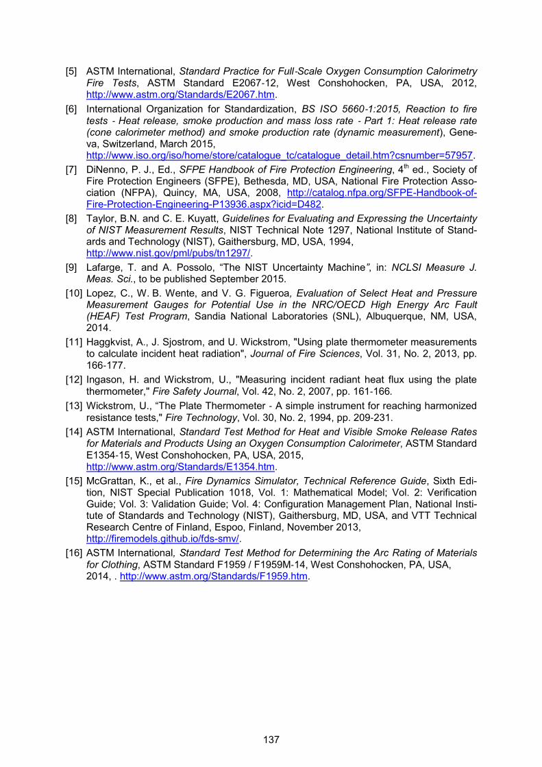
[5] ASTM International, Standard Practice for Full‐Scale Oxygen Consumption Calorimetry Fire Tests, ASTM Standard E2067‐12, West Conshohocken, PA, USA, 2012, http://www.astm.org/Standards/E2067.htm.
[6] International Organization for Standardization, BS ISO 5660‐1:2015, Reaction to fire tests ‐ Heat release, smoke production and mass loss rate ‐ Part 1: Heat release rate (cone calorimeter method) and smoke production rate (dynamic measurement), Gene-va, Switzerland, March 2015, http://www.iso.org/iso/home/store/catalogue_tc/catalogue_detail.htm?csnumber=57957.
[7] DiNenno, P. J., Ed., SFPE Handbook of Fire Protection Engineering, 4th ed., Society of Fire Protection Engineers (SFPE), Bethesda, MD, USA, National Fire Protection Asso-ciation (NFPA), Quincy, MA, USA, 2008, http://catalog.nfpa.org/SFPE-Handbook-of-Fire-Protection-Engineering-P13936.aspx?icid=D482.
[8] Taylor, B.N. and C. E. Kuyatt, Guidelines for Evaluating and Expressing the Uncertainty of NIST Measurement Results, NIST Technical Note 1297, National Institute of Stand-ards and Technology (NIST), Gaithersburg, MD, USA, 1994, http://www.nist.gov/pml/pubs/tn1297/.
[9] Lafarge, T. and A. Possolo, “The NIST Uncertainty Machine”, in: NCLSI Measure J. Meas. Sci., to be published September 2015.
[10] Lopez, C., W. B. Wente, and V. G. Figueroa, Evaluation of Select Heat and Pressure Measurement Gauges for Potential Use in the NRC/OECD High Energy Arc Fault (HEAF) Test Program, Sandia National Laboratories (SNL), Albuquerque, NM, USA, 2014.
[11] Haggkvist, A., J. Sjostrom, and U. Wickstrom, "Using plate thermometer measurements to calculate incident heat radiation", Journal of Fire Sciences, Vol. 31, No. 2, 2013, pp. 166‐177.
[12] Ingason, H. and Wickstrom, U., "Measuring incident radiant heat flux using the plate thermometer," Fire Safety Journal, Vol. 42, No. 2, 2007, pp. 161‐166.
[13] Wickstrom, U., “The Plate Thermometer ‐ A simple instrument for reaching harmonized resistance tests," Fire Technology, Vol. 30, No. 2, 1994, pp. 209‐231.
[14] ASTM International, Standard Test Method for Heat and Visible Smoke Release Rates for Materials and Products Using an Oxygen Consumption Calorimeter, ASTM Standard E1354‐15, West Conshohocken, PA, USA, 2015, http://www.astm.org/Standards/E1354.htm.
[15] McGrattan, K., et al., Fire Dynamics Simulator, Technical Reference Guide, Sixth Edi-tion, NIST Special Publication 1018, Vol. 1: Mathematical Model; Vol. 2: Verification Guide; Vol. 3: Validation Guide; Vol. 4: Configuration Management Plan, National Insti-tute of Standards and Technology (NIST), Gaithersburg, MD, USA, and VTT Technical Research Centre of Finland, Espoo, Finland, November 2013, http://firemodels.github.io/fds-smv/.
[16] ASTM International, Standard Test Method for Determining the Arc Rating of Materials for Clothing, ASTM Standard F1959 / F1959M‐14, West Conshohocken, PA, USA, 2014, . http://www.astm.org/Standards/F1959.htm.
137

23st International Conference on Structural Mechanics in Reactor Technology (SMiRT 23) - 14th
International Post-Conference Seminar on “FIRE SAFETY IN NUCLEAR POWER PLANTS AND INSTALLATIONS“
ASSESSMENT OF THE BURNING BEHAVIOR OF PROTECTED AND UNPROTECTED CABLES AND CABLE TRAYS IN NUCLEAR
INSTALLATIONS USING SMALL- AND LARGE-SCALE EXPERIMENTS
Matthias Siemon1, Olaf Riese1
, Jochen Zehfuß1
1 Institut für Baustoffe, Massivbau und Brandschutz (iBMB), Technische Universität Braunschweig, Braunschweig, Germany
ABSTRACT Electric installations and cables are a main fire risk source in industrial buildings and power plants. In general, cables and cable systems are associated with flash-over phenomena due to pyrolysis of fuel gases induced by the heat of an adjacent fire, fire spread along cable trays affecting additional areas besides the fire origin, being an ignition source due to mal-function. If burning, cables can emit large amounts of smoke and toxic products affecting oc-cupants as well as the long-term functionality of structure and installations. Paying attention to these risks has led to the development of fire retardant non-corrosive (non-halogenated) cables which are qualified to reduce the individual or all of the risks mentioned. For existing installations in industrial buildings and power plants with halogenated cables, different pro-tection measures are available and widely applied retroactively. Important protective measures are intumescent or ablative coatings, cable casings and bindings. For qualification of the effects of the protection measures, small-scale tests investigating a single cable specimen as well as large-scale cable tray test setups have been developed and carried out in the last 20 years at iBMB. In this paper, these test results are analysed re-garding their effects on the heat release, ignition time and fire spread over cable trays. Fur-thermore, national and international research projects have investigated the burning behav-iour of different cable types, tray installations, tray loading and spacing and ventilation condi-tions. As a conclusion, the main outcomes of past researches are summarized. Influence factors (e.g. pre-heating due to high power utilization, influence of cable aging) which have not been accounted for in detail are emphasized. The modelling of unprotected cables has been internationally studied in recent years. For fu-ture applications, the question of applicability of recently developed sub-models on the fire behaviour of protected cables has to be answered. The results presented in this paper may provide the basis for the planning of further validation experiments to the fire performance of protected cables. INTRODUCTION During the last 20 years, extensive research efforts have been taken to investigate the burn-ing behaviour of protected and unprotected cable trays equipped with PVC cables. One goal was the need of detailed requirements for trays and electrical installations installed in nucle-ar power plants to account for the risks of self-ignition, flash-over and fire spreading. In some cases, e.g. during operation, the replacement of halogenated cables with FRNC (fire retard-ant non-corrosive) cables is difficult. This led to the utilization of protective measures such as intumescent coatings, ablation coatings or protection bindings to prevent the risks of fire spreading, flash-over and burning.
138
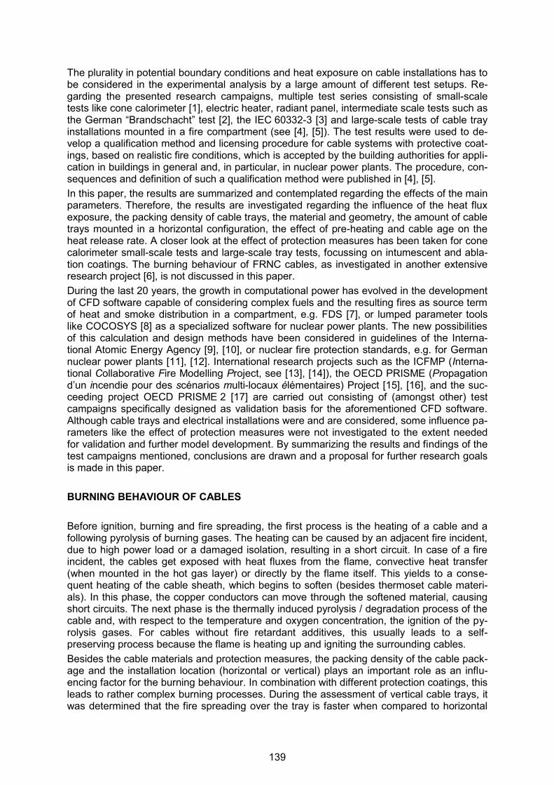
The plurality in potential boundary conditions and heat exposure on cable installations has to be considered in the experimental analysis by a large amount of different test setups. Re-garding the presented research campaigns, multiple test series consisting of small-scale tests like cone calorimeter [1], electric heater, radiant panel, intermediate scale tests such as the German “Brandschacht” test [2], the IEC 60332-3 [3] and large-scale tests of cable tray installations mounted in a fire compartment (see [4], [5]). The test results were used to de-velop a qualification method and licensing procedure for cable systems with protective coat-ings, based on realistic fire conditions, which is accepted by the building authorities for appli-cation in buildings in general and, in particular, in nuclear power plants. The procedure, con-sequences and definition of such a qualification method were published in [4], [5]. In this paper, the results are summarized and contemplated regarding the effects of the main parameters. Therefore, the results are investigated regarding the influence of the heat flux exposure, the packing density of cable trays, the material and geometry, the amount of cable trays mounted in a horizontal configuration, the effect of pre-heating and cable age on the heat release rate. A closer look at the effect of protection measures has been taken for cone calorimeter small-scale tests and large-scale tray tests, focussing on intumescent and abla-tion coatings. The burning behaviour of FRNC cables, as investigated in another extensive research project [6], is not discussed in this paper. During the last 20 years, the growth in computational power has evolved in the development of CFD software capable of considering complex fuels and the resulting fires as source term of heat and smoke distribution in a compartment, e.g. FDS [7], or lumped parameter tools like COCOSYS [8] as a specialized software for nuclear power plants. The new possibilities of this calculation and design methods have been considered in guidelines of the Interna-tional Atomic Energy Agency [9], [10], or nuclear fire protection standards, e.g. for German nuclear power plants [11], [12]. International research projects such as the ICFMP (Interna-tional Collaborative Fire Modelling Project, see [13], [14]), the OECD PRISME (Propagation d’un incendie pour des scénarios multi-locaux élémentaires) Project [15], [16], and the suc-ceeding project OECD PRISME 2 [17] are carried out consisting of (amongst other) test campaigns specifically designed as validation basis for the aforementioned CFD software. Although cable trays and electrical installations were and are considered, some influence pa-rameters like the effect of protection measures were not investigated to the extent needed for validation and further model development. By summarizing the results and findings of the test campaigns mentioned, conclusions are drawn and a proposal for further research goals is made in this paper. BURNING BEHAVIOUR OF CABLES Before ignition, burning and fire spreading, the first process is the heating of a cable and a following pyrolysis of burning gases. The heating can be caused by an adjacent fire incident, due to high power load or a damaged isolation, resulting in a short circuit. In case of a fire incident, the cables get exposed with heat fluxes from the flame, convective heat transfer (when mounted in the hot gas layer) or directly by the flame itself. This yields to a conse-quent heating of the cable sheath, which begins to soften (besides thermoset cable materi-als). In this phase, the copper conductors can move through the softened material, causing short circuits. The next phase is the thermally induced pyrolysis / degradation process of the cable and, with respect to the temperature and oxygen concentration, the ignition of the py-rolysis gases. For cables without fire retardant additives, this usually leads to a self-preserving process because the flame is heating up and igniting the surrounding cables. Besides the cable materials and protection measures, the packing density of the cable pack-age and the installation location (horizontal or vertical) plays an important role as an influ-encing factor for the burning behaviour. In combination with different protection coatings, this leads to rather complex burning processes. During the assessment of vertical cable trays, it was determined that the fire spreading over the tray is faster when compared to horizontal
139

cable trays. For horizontal trays, a higher packing density, reached by a smaller tray with the same amount of cables, e.g. in the CHRISTIFIRE project [19], or by adding additional cable layers [18] showed that the maximum heat release rate is reduced up to 100 % and more. Coated cables show a discontinuous flame spread because the pyrolysis gases can only es-cape through cracks in the coating. Coated cables usually burn at areas separated from each other. Cracks in the coating occur during the thermal expansion of the cable when the coating cannot take the tensile strains, which increase with increasing temperature. Intu-mescent coatings with an adequate thickness are capable of protecting themselves by clos-ing the gaps with newly produced foam. Ablation coatings are more sensitive to cracking be-cause they do not protect themselves. In general, the risk of cracking increases with higher heating rates and larger heat fluxes [18]. The aforementioned findings are based on extensive research mainly based on PVC cables without significant amounts of flame retardant compounds. The burning behaviour of FRNC cables is assessed and published in [6] and [19]. CURRENT PROTECTION MEASURES Intumescent Coating Painted intumescent coatings react to temperature exposure respectively heat fluxes with foaming and swelling, increasing the volume by magnitudes. This reaction can also be endo-thermic. The main protection mechanism is the foam, leading to thicknesses up to 100 x the original thickness. In case of a fire, the foam protects the cable sheath from high heat fluxes due to its low heat conductivity and isolates the whole cable against the hot environment. Due to this, the heating of the cable is slowed, the beginning of the pyrolysis is delayed and the pyrolysis rate is lowered in total. In addition, the foam prevents the pyrolysis gases from flowing into the combustion zone. As consequence, the ignition of the cables is delayed and the heat release rate is lowered. Ablation Coating Based on a different protection mechanism, the ablation coating systems divest energy due to an endothermic reaction, when heated. This reaction takes place until the whole ablation coating is consumed. During the reaction, even a cooling of the cables can be seen due to the strong endothermic reaction. After the consumption of the ablation material, a relatively thin material layer is left. In case of a fire, the heating of the protected cables is significantly delayed until all ablation coating material is consumed. After this point, the heating can be compared to an unprotected cable. The thickness of the remaining char (for the materials assessed) is usually too low to have a significant isolative effect. Specific Measures at Connections and Mounting Points When mounted on cable trays, the fixing points and mounting elements yield to gaps and in-sufficiently coated spots on the cable surface. To avoid fire spread at the mounting points, the construction is protected with glass fibre wires, which for themselves, are also protected with intumescent coating. These measures were taken for vertically mounted cables during the large-scale experiments [18]. In nuclear installations, water is used for decontamination measures after an incident. Some intumescent coatings get damaged when exposed to water. In this case, the coating itself has to be protected with an additional, waterproof coating which does not constrain the foam development in case of fire.
140
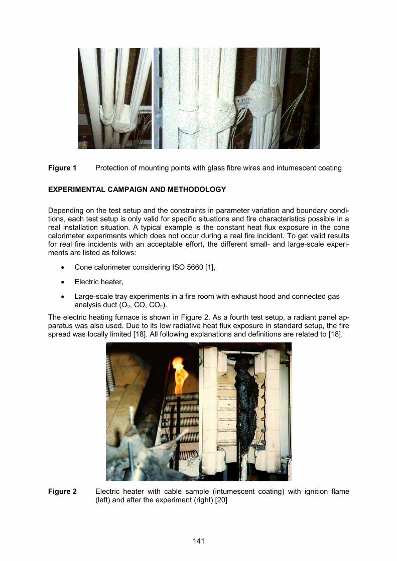
Figure 1 Protection of mounting points with glass fibre wires and intumescent coating EXPERIMENTAL CAMPAIGN AND METHODOLOGY Depending on the test setup and the constraints in parameter variation and boundary condi-tions, each test setup is only valid for specific situations and fire characteristics possible in a real installation situation. A typical example is the constant heat flux exposure in the cone calorimeter experiments which does not occur during a real fire incident. To get valid results for real fire incidents with an acceptable effort, the different small- and large-scale experi-ments are listed as follows:
Cone calorimeter considering ISO 5660 [1],
Electric heater,
Large-scale tray experiments in a fire room with exhaust hood and connected gas analysis duct (O2, CO, CO2).
The electric heating furnace is shown in Figure 2. As a fourth test setup, a radiant panel ap-paratus was also used. Due to its low radiative heat flux exposure in standard setup, the fire spread was locally limited [18]. All following explanations and definitions are related to [18].
Figure 2 Electric heater with cable sample (intumescent coating) with ignition flame (left) and after the experiment (right) [20]
141

In Table 1, the settings, parameters and boundary conditions are listed for the test setups described above. The underlined text marks parameter variations or bandwidths of assessed parameters. Table 1 Test matrix for the assessment of the burning behaviour of cables and cable
trays
Tests Small-scale Tests Large-scale Tests
Parameter
Cone Calorimeter Electric Heater Vertical and Horizontal Tray Tests in a Fire Compartment
Type/age of cable
6 new, 2 used
2 new 4 new. 1 used
Orientation of the cable
Horizontal no variation horizontal, vertical
Packing density single cable, 3 cables, full (10 x 10 cm²)
single cable one cable layer, two cable layer, three cable layer, control cables, power cables,
Number of cable trays and position to neighbouring trays
parameter varies considering practical issues
parameter varies considering practical issues
horizontal: 1, 2, 3 trays, vertical: single tray, 3 trays side by side, 3 trays in a row
Protective measures
intumescent coating, ablation coating
intumescent coating, ablation coating, combination of both
intumescent coating, ablation coating, tray bindings
Thermal exposure
radiative 10 - 60 kW/m²
pre-heated, max 400 °C
pre-heated, max. 450 °C
Ignition source electric arc Diffusion flame (methane)
diffusion flame (propane) using a sand burner with 50 - 180 kW, suspended cables, max. 300 kW
Ventilation no variation no variation opening with 2.6 m²
Position in the fire room
parameter varies considering practical issues
parameter varies considering practical issues
horizontal: lower or middle position
Every test setup is based on a specific risk situation. In the large-scale room fire tests, a sit-uation occurring in real fire incidents is simulated. A possible ignition source (cleaning mate-rials, trash bins, wooden furniture or liquid pools is replaced by a sand burner which can be adjusted in power, location and (limited) in geometry, simulating the possible real fire source. A fully developed fire adjacent to the trays is simulated by pre-heating the fire room (large-scale tests) or exposure with an appropriate heat flux (small-scale tests). The results of
142
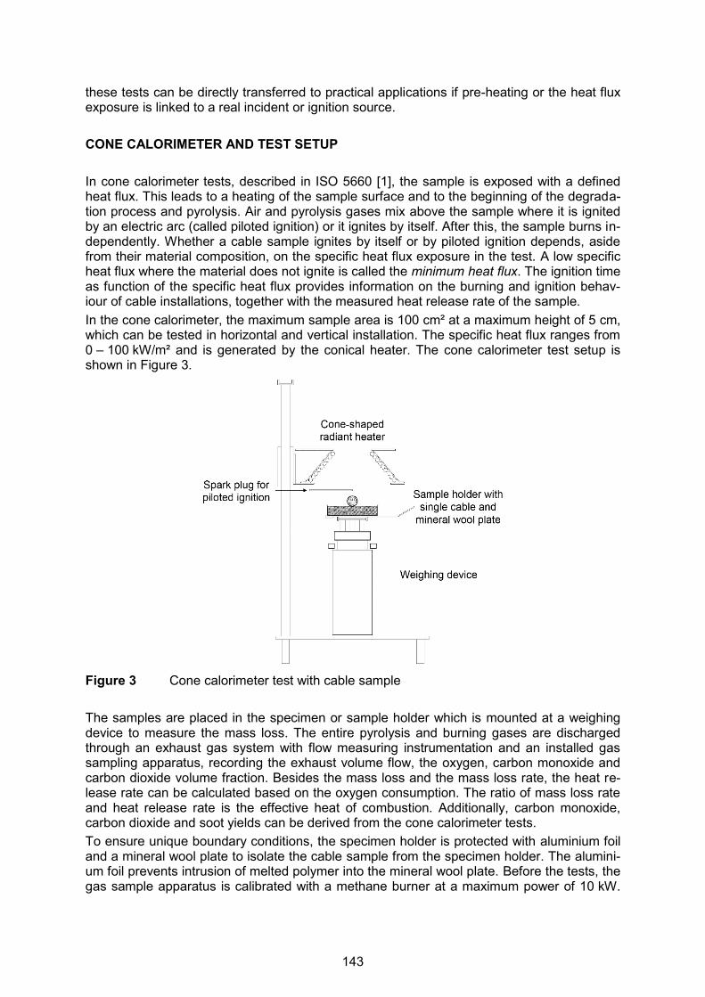
these tests can be directly transferred to practical applications if pre-heating or the heat flux exposure is linked to a real incident or ignition source. CONE CALORIMETER AND TEST SETUP In cone calorimeter tests, described in ISO 5660 [1], the sample is exposed with a defined heat flux. This leads to a heating of the sample surface and to the beginning of the degrada-tion process and pyrolysis. Air and pyrolysis gases mix above the sample where it is ignited by an electric arc (called piloted ignition) or it ignites by itself. After this, the sample burns in-dependently. Whether a cable sample ignites by itself or by piloted ignition depends, aside from their material composition, on the specific heat flux exposure in the test. A low specific heat flux where the material does not ignite is called the minimum heat flux. The ignition time as function of the specific heat flux provides information on the burning and ignition behav-iour of cable installations, together with the measured heat release rate of the sample. In the cone calorimeter, the maximum sample area is 100 cm² at a maximum height of 5 cm, which can be tested in horizontal and vertical installation. The specific heat flux ranges from 0 – 100 kW/m² and is generated by the conical heater. The cone calorimeter test setup is shown in Figure 3.
Figure 3 Cone calorimeter test with cable sample The samples are placed in the specimen or sample holder which is mounted at a weighing device to measure the mass loss. The entire pyrolysis and burning gases are discharged through an exhaust gas system with flow measuring instrumentation and an installed gas sampling apparatus, recording the exhaust volume flow, the oxygen, carbon monoxide and carbon dioxide volume fraction. Besides the mass loss and the mass loss rate, the heat re-lease rate can be calculated based on the oxygen consumption. The ratio of mass loss rate and heat release rate is the effective heat of combustion. Additionally, carbon monoxide, carbon dioxide and soot yields can be derived from the cone calorimeter tests. To ensure unique boundary conditions, the specimen holder is protected with aluminium foil and a mineral wool plate to isolate the cable sample from the specimen holder. The alumini-um foil prevents intrusion of melted polymer into the mineral wool plate. Before the tests, the gas sample apparatus is calibrated with a methane burner at a maximum power of 10 kW.
143
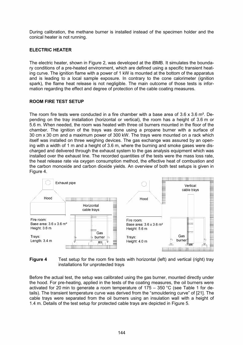
During calibration, the methane burner is installed instead of the specimen holder and the conical heater is not running. ELECTRIC HEATER The electric heater, shown in Figure 2, was developed at the iBMB. It simulates the bounda-ry conditions of a pre-heated environment, which are defined using a specific transient heat-ing curve. The ignition flame with a power of 1 kW is mounted at the bottom of the apparatus and is leading to a local sample exposure. In contrary to the cone calorimeter (ignition spark), the flame heat release is not negligible. The main outcome of those tests is infor-mation regarding the effect and degree of protection of the cable coating measures. ROOM FIRE TEST SETUP The room fire tests were conducted in a fire chamber with a base area of 3.6 x 3.6 m². De-pending on the tray installation (horizontal or vertical), the room has a height of 3.6 m or 5.6 m. When needed, the room was heated with three oil burners mounted in the floor of the chamber. The ignition of the trays was done using a propane burner with a surface of 30 cm x 30 cm and a maximum power of 300 kW. The trays were mounted on a rack which itself was installed on three weighing devices. The gas exchange was assured by an open-ing with a width of 1 m and a height of 3.6 m, where the burning and smoke gases were dis-charged and delivered through the exhaust system to the gas analysis equipment which was installed over the exhaust line. The recorded quantities of the tests were the mass loss rate, the heat release rate via oxygen consumption method, the effective heat of combustion and the carbon monoxide and carbon dioxide yields. An overview of both test setups is given in Figure 4.
Figure 4 Test setup for the room fire tests with horizontal (left) and vertical (right) tray installations for unprotected trays
Before the actual test, the setup was calibrated using the gas burner, mounted directly under the hood. For pre-heating, applied in the tests of the coating measures, the oil burners were activated for 20 min to generate a room temperature of 175 – 350 °C (see Table 1 for de-tails). The transient temperature curve was derived from the “smouldering curve” of [21]. The cable trays were separated from the oil burners using an insulation wall with a height of 1.4 m. Details of the test setup for protected cable trays are depicted in Figure 5.
144
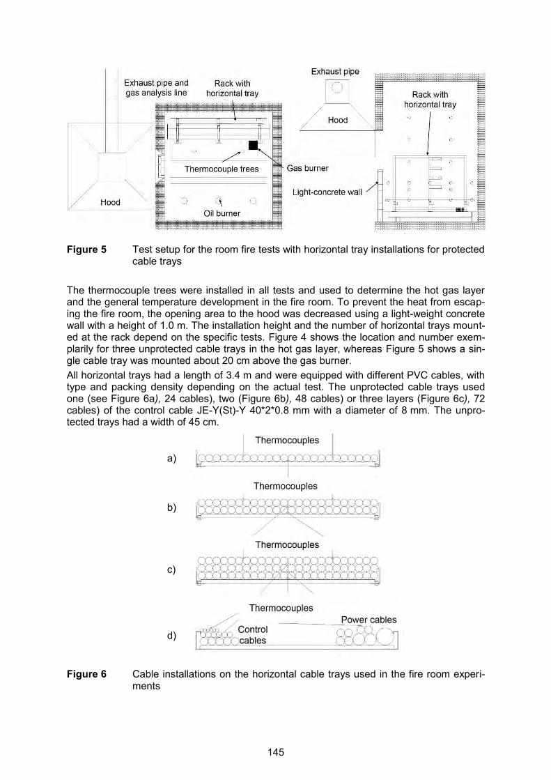
Figure 5 Test setup for the room fire tests with horizontal tray installations for protected cable trays
The thermocouple trees were installed in all tests and used to determine the hot gas layer and the general temperature development in the fire room. To prevent the heat from escap-ing the fire room, the opening area to the hood was decreased using a light-weight concrete wall with a height of 1.0 m. The installation height and the number of horizontal trays mount-ed at the rack depend on the specific tests. Figure 4 shows the location and number exem-plarily for three unprotected cable trays in the hot gas layer, whereas Figure 5 shows a sin-gle cable tray was mounted about 20 cm above the gas burner. All horizontal trays had a length of 3.4 m and were equipped with different PVC cables, with type and packing density depending on the actual test. The unprotected cable trays used one (see Figure 6a), 24 cables), two (Figure 6b), 48 cables) or three layers (Figure 6c), 72 cables) of the control cable JE-Y(St)-Y 40*2*0.8 mm with a diameter of 8 mm. The unpro-tected trays had a width of 45 cm.
Figure 6 Cable installations on the horizontal cable trays used in the fire room experi-ments
a)
b)
c)
d)
145

The trays assessed for the analysis of the protection measures were equipped with seven different cable types, all containing PVC. They were equipped as outlined in Figure 6d). On the side facing the wall of the fire room, four different types of power cables with a diameter from 20 mm to 45 mm were located, whereas the control cables face into the fire room. This tray load was used as a standard load in most of the experiments with ablation and intumes-cent coatings. More details regarding the cables are published in [18]. The results of the analysis of vertical tray installations are also published in [18]. SMALL-SCALE TEST RESULTS Cone Calorimeter Cone calorimeter results were conducted for several cable types, cable ages, cable amounts and heat fluxes ranging from 15 to 60 kW/m². The effect of intumescent coating on the igni-tion time and the heat release rate is depicted in Figure 7 with dotted lines and compared to the unprotected cable (continuous line). It can be shown that the ignition is delayed by at least 450 s. The maximum heat release rate is reduced from 12 kW/m to about 3 kW/m. The results are representative for other intumescent coatings investigated with the cone calorim-eter. The other protection coating is the ablation coating, based on an endothermic reaction which consumes energy when heated. The effect of the ablation coating was investigated for one mixture and is shown in Figure 7 as dashed lines. The type of cable used in the experiments is the same as for the intumescent coating. The ablation coating leads to a delay in ignition of about 90 – 120 s. The maximum heat release rate is lowered from 12 kW/m to about 8 kW/m. All three repetition tests show a similar behaviour.
Figure 7 Specific heat release rate and ignition times measured for protected and un-protected cables type JE-Y(St)-Y 40*2*0.8 mm at 50 kW/m²
0
2
4
6
8
10
12
14
0 400 800 1200 1600 2000 2400
Spec
ific
heat
rele
ase
rate
[kW
/m]
Time [s]
Control cable JE-Y(St)-Y 40*2*0.8 mm at 50 kW/m²
w/o coating, ignition time: 20 s
ablation coating, ignition time 110 s
ablation coating, ignition time 136 s
ablation coating, ignition time 145 s
intumescent coating, ignition time 474 s
ignition time: 693 s
146
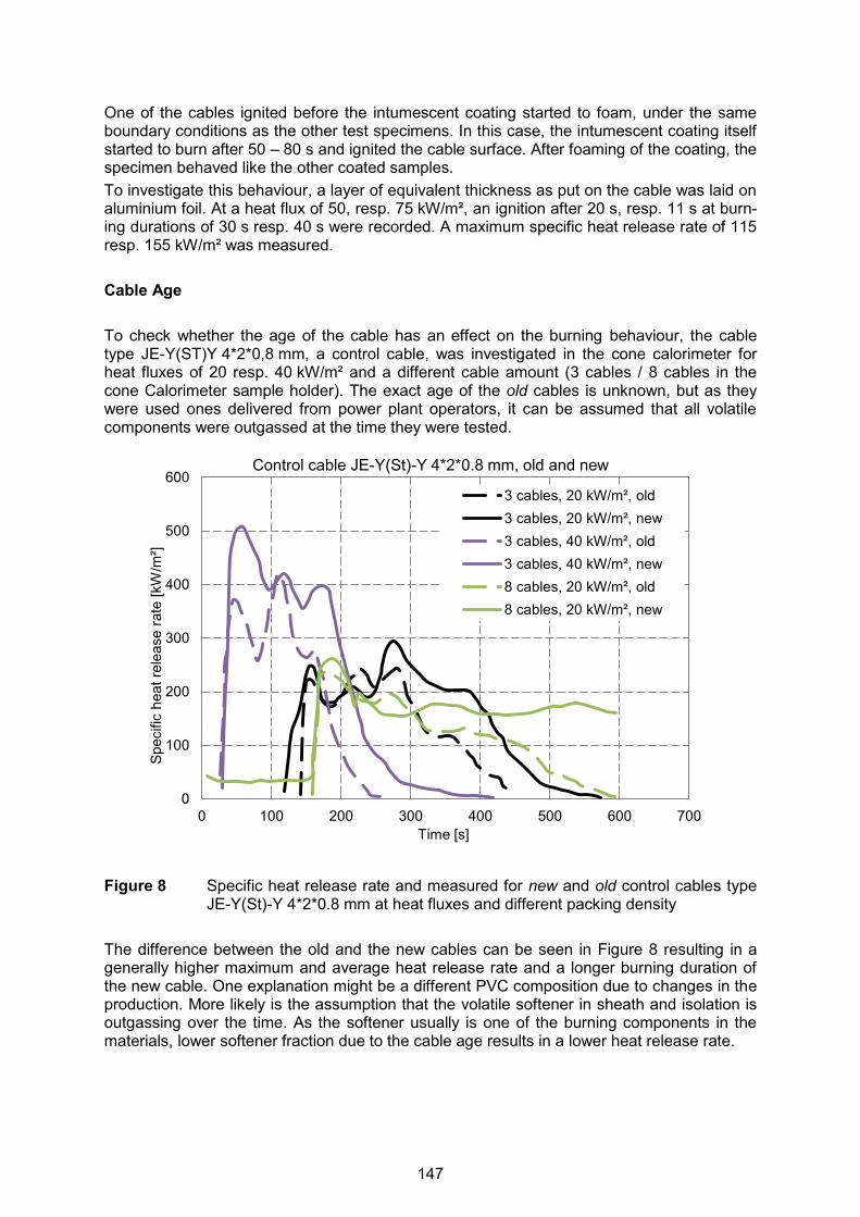
One of the cables ignited before the intumescent coating started to foam, under the same boundary conditions as the other test specimens. In this case, the intumescent coating itself started to burn after 50 – 80 s and ignited the cable surface. After foaming of the coating, the specimen behaved like the other coated samples. To investigate this behaviour, a layer of equivalent thickness as put on the cable was laid on aluminium foil. At a heat flux of 50, resp. 75 kW/m², an ignition after 20 s, resp. 11 s at burn-ing durations of 30 s resp. 40 s were recorded. A maximum specific heat release rate of 115 resp. 155 kW/m² was measured. Cable Age To check whether the age of the cable has an effect on the burning behaviour, the cable type JE-Y(ST)Y 4*2*0,8 mm, a control cable, was investigated in the cone calorimeter for heat fluxes of 20 resp. 40 kW/m² and a different cable amount (3 cables / 8 cables in the cone Calorimeter sample holder). The exact age of the old cables is unknown, but as they were used ones delivered from power plant operators, it can be assumed that all volatile components were outgassed at the time they were tested.
Figure 8 Specific heat release rate and measured for new and old control cables type
JE-Y(St)-Y 4*2*0.8 mm at heat fluxes and different packing density The difference between the old and the new cables can be seen in Figure 8 resulting in a generally higher maximum and average heat release rate and a longer burning duration of the new cable. One explanation might be a different PVC composition due to changes in the production. More likely is the assumption that the volatile softener in sheath and isolation is outgassing over the time. As the softener usually is one of the burning components in the materials, lower softener fraction due to the cable age results in a lower heat release rate.
0
100
200
300
400
500
600
0 100 200 300 400 500 600 700
Spec
ific
heat
rele
ase
rate
[kW
/m²]
Time [s]
Control cable JE-Y(St)-Y 4*2*0.8 mm, old and new
3 cables, 20 kW/m², old3 cables, 20 kW/m², new3 cables, 40 kW/m², old3 cables, 40 kW/m², new8 cables, 20 kW/m², old8 cables, 20 kW/m², new
147
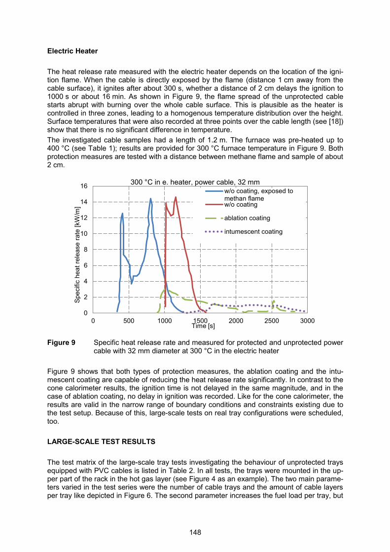
Electric Heater The heat release rate measured with the electric heater depends on the location of the igni-tion flame. When the cable is directly exposed by the flame (distance 1 cm away from the cable surface), it ignites after about 300 s, whether a distance of 2 cm delays the ignition to 1000 s or about 16 min. As shown in Figure 9, the flame spread of the unprotected cable starts abrupt with burning over the whole cable surface. This is plausible as the heater is controlled in three zones, leading to a homogenous temperature distribution over the height. Surface temperatures that were also recorded at three points over the cable length (see [18]) show that there is no significant difference in temperature. The investigated cable samples had a length of 1.2 m. The furnace was pre-heated up to 400 °C (see Table 1); results are provided for 300 °C furnace temperature in Figure 9. Both protection measures are tested with a distance between methane flame and sample of about 2 cm.
Figure 9 Specific heat release rate and measured for protected and unprotected power cable with 32 mm diameter at 300 °C in the electric heater
Figure 9 shows that both types of protection measures, the ablation coating and the intu-mescent coating are capable of reducing the heat release rate significantly. In contrast to the cone calorimeter results, the ignition time is not delayed in the same magnitude, and in the case of ablation coating, no delay in ignition was recorded. Like for the cone calorimeter, the results are valid in the narrow range of boundary conditions and constraints existing due to the test setup. Because of this, large-scale tests on real tray configurations were scheduled, too. LARGE-SCALE TEST RESULTS The test matrix of the large-scale tray tests investigating the behaviour of unprotected trays equipped with PVC cables is listed in Table 2. In all tests, the trays were mounted in the up-per part of the rack in the hot gas layer (see Figure 4 as an example). The two main parame-ters varied in the test series were the number of cable trays and the amount of cable layers per tray like depicted in Figure 6. The second parameter increases the fuel load per tray, but
0
2
4
6
8
10
12
14
16
0 500 1000 1500 2000 2500 3000
Spec
ific
heat
rele
ase
rate
[kW
/m]
Time [s]
300 °C in e. heater, power cable, 32 mm w/o coating, exposed tomethan flamew/o coating
ablation coating
intumescent coating
148

on the other hand reduces the surface to volume ratio of the cable package as, e.g. for the tray with three cable layers, the second layer is protected by both upper and lower adjacent layers. Table 2 Test matrix of the large-scale tray tests with unprotected cables and main re-
sults (yields as average values, data from [18])
1 Cable Layer 2 Cable Layers 3 Cable Layers
1 Tr
ay
Test 3 Test 4 HRRmax 275 kW HRRmax 230 kW tmax 210 s tmax 240 s EHC 10 kJ/g EHC 10.5 kJ/g YCO2,Av 0.6 kg/kg YCO2,Av 0.65 kg/kg YCO,Av 0.05 kg/kg YCO,Av 0.06 kg/kg
2 Tr
ays
Test 5 Test 6 Test 9 Test 10 HRRmax 440 kW HRRmax 275 kW HRRmax 430, 250 kW HRRmax 380 kW
tmax 660 s tmax 300, 3150 s tmax 360, 2400 s tmax 160 s
EHC 11 kJ/g EHC 10 kJ/g EHC 8 kJ/g EHC 6.5 kJ/g
YCO2,Av 0.7 kg/kg YCO2,Av 0.75 kg/kg YCO2,Av 0.33 kg/kg YCO2,Av (0.3 kg/kg)
YCO,Av 0.09 kg/kg YCO,Av 0.95 kg/kg YCO,Av 0.1 kg/kg YCO,Av (0.03 kg/kg)
Test 10a HRRmax 320 kW
tmax 2050 s
EHC 11 kJ/g
YCO2,Av 0.5 kg/kg
YCO,Av 0.13 kg/kg
3 Tr
ays
Test 11 Test 7 Test 8 HRRmax 880 kW HRRmax 700 kW HRRmax 480 kW tmax 1020 s tmax 1650 s tmax 360 s EHC 14 kJ/g EHC 11.5 kJ/g EHC 9 kJ/g YCO2,Av 0.85 kg/kg YCO2,Av 0.7 kg/kg YCO2,Av 0.13 kg/kg YCO,Av 0.16 kg/kg YCO,Av 0.11 kg/kg YCO,Av 0.05 kg/kg
Test 8a
HRRmax 800 kW
tmax 1690 s
EHC 9.5 kJ/g
YCO2,Av 0.7 kg/kg
YCO,Av 0.12 kg/kg
149

It has to be kept in mind that this approach is different from the one taken in the CHRISTIFIRE project [19] where the packing density is increased by decreasing the tray width. The effect on the heat release rate and the fire spread is comparable, but, on the oth-er hand, the total amount of combustible mass is kept constant. The influence of the packing density is depicted in Figure 10, showing the results of the heat release rate of the tests number 5 (1 cable layer), 9 (2 cable layer), 10 (3 cable layer) in Fig-ure 11a and the results of the tests number 11 (1 cable layer), 7 (2 cable layer), 8 (3 cable layer) in Figure 10b. One layer, i.e. 24 cables per tray, leads to the highest maximum heat release rate, in tests with 2 trays installed as well as in tests with 3 trays. One reason is the flame spread, which does not stop at the ends of the tray, resulting in a larger burning sur-face area. The fire spread velocity is also slower for trays with more than one cable layer. The effect of the number of trays is shown in Figure 10, with the combination of tests number 3 (1 tray), 5 (2 trays), 11 (3 trays) in Figure 10c, always equipped with one cable layer, and tests number 4 (1 tray), 9 (2 trays), 7 (3 trays) in Figure 10d, always equipped with two cable layers. As expected, more trays lead to a higher heat release rate in maximum.
Figure 10 Heat release rate measured in large-scale room fire tests for trays located at the upper part of the rack (hot gas layer)
For two cable layers on each tray, the influence of the packing density can be seen, as the comparison of tests 5, 9 and 10 in Figure 10a shows. On the upper surface of the lowest tray, ignition starts at the same time like seen in tests with a single tray. The ignition of the upper surface of the second tray is slightly delayed (the same for test 10). If both trays are equipped with one cable layer, the fire spreads faster on the first tray than on the ones
0100200300400500600700800900
1000
0 500 1000 1500 2000 2500
Hea
t rel
ease
rate
[kW
/m]
a) 2 trays, variation of cable layers
1 cable layer2 cable layer3 cable layer
0100200300400500600700800900
1000
0 500 1000 1500 2000 2500
b) 3 trays, variation of cable layers
1 cable layer2 cable layer3 cable layer
0100200300400500600700800900
1000
0 500 1000 1500 2000 2500
Hea
t rel
ease
rate
[kW
/m]
Time [s]
c) 1 cable layer, variation of trays
1 tray2 trays3 trays
0100200300400500600700800900
1000
0 500 1000 1500 2000 2500Time [s]
d) 2 cable layer, variation of trays
1 tray2 trays3 trays
150
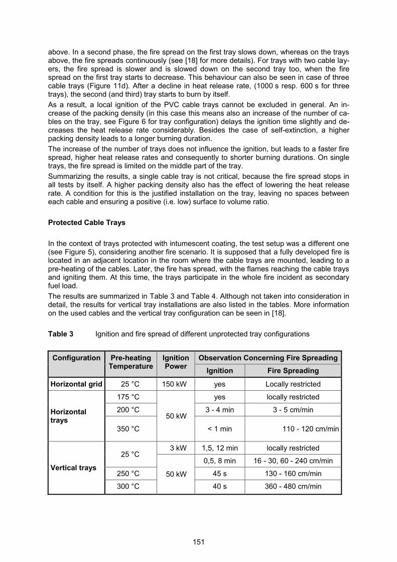
above. In a second phase, the fire spread on the first tray slows down, whereas on the trays above, the fire spreads continuously (see [18] for more details). For trays with two cable lay-ers, the fire spread is slower and is slowed down on the second tray too, when the fire spread on the first tray starts to decrease. This behaviour can also be seen in case of three cable trays (Figure 11d). After a decline in heat release rate, (1000 s resp. 600 s for three trays), the second (and third) tray starts to burn by itself. As a result, a local ignition of the PVC cable trays cannot be excluded in general. An in-crease of the packing density (in this case this means also an increase of the number of ca-bles on the tray, see Figure 6 for tray configuration) delays the ignition time slightly and de-creases the heat release rate considerably. Besides the case of self-extinction, a higher packing density leads to a longer burning duration. The increase of the number of trays does not influence the ignition, but leads to a faster fire spread, higher heat release rates and consequently to shorter burning durations. On single trays, the fire spread is limited on the middle part of the tray. Summarizing the results, a single cable tray is not critical, because the fire spread stops in all tests by itself. A higher packing density also has the effect of lowering the heat release rate. A condition for this is the justified installation on the tray, leaving no spaces between each cable and ensuring a positive (i.e. low) surface to volume ratio. Protected Cable Trays In the context of trays protected with intumescent coating, the test setup was a different one (see Figure 5), considering another fire scenario. It is supposed that a fully developed fire is located in an adjacent location in the room where the cable trays are mounted, leading to a pre-heating of the cables. Later, the fire has spread, with the flames reaching the cable trays and igniting them. At this time, the trays participate in the whole fire incident as secondary fuel load. The results are summarized in Table 3 and Table 4. Although not taken into consideration in detail, the results for vertical tray installations are also listed in the tables. More information on the used cables and the vertical tray configuration can be seen in [18]. Table 3 Ignition and fire spread of different unprotected tray configurations
Configuration Pre-heating Temperature
Ignition Power
Observation Concerning Fire Spreading Ignition Fire Spreading
Horizontal grid 25 °C 150 kW yes Locally restricted
Horizontal trays
175 °C
50 kW
yes locally restricted
200 °C 3 - 4 min 3 - 5 cm/min
350 °C < 1 min 110 - 120 cm/min
Vertical trays
25 °C 3 kW 1,5, 12 min locally restricted
50 kW
0,5, 8 min 16 - 30, 60 - 240 cm/min
250 °C 45 s 130 - 160 cm/min
300 °C 40 s 360 - 480 cm/min
151
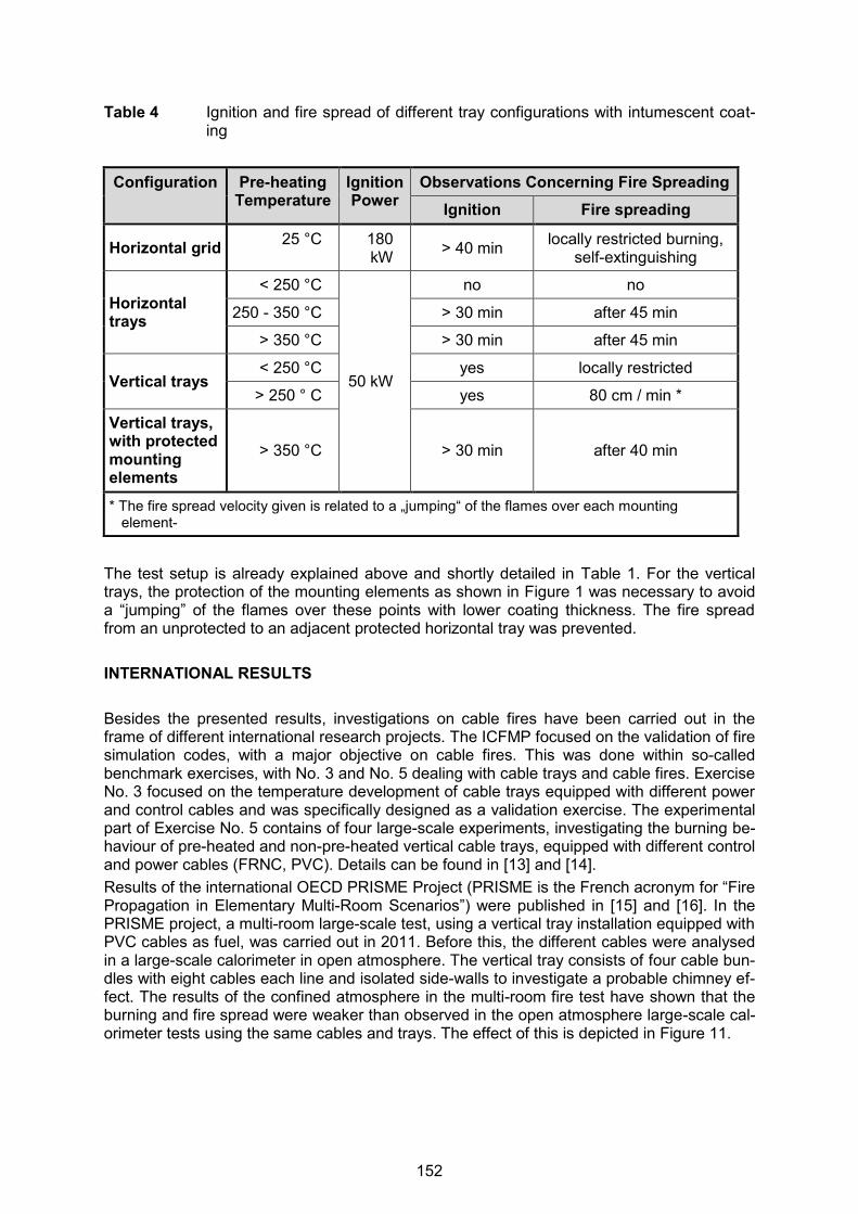
Table 4 Ignition and fire spread of different tray configurations with intumescent coat-ing
Configuration Pre-heating Temperature
Ignition Power
Observations Concerning Fire Spreading Ignition Fire spreading
Horizontal grid 25 °C 180 kW > 40 min locally restricted burning,
self-extinguishing
Horizontal trays
< 250 °C
50 kW
no no
250 - 350 °C > 30 min after 45 min
> 350 °C > 30 min after 45 min
Vertical trays < 250 °C yes locally restricted
> 250 ° C yes 80 cm / min *
Vertical trays, with protected mounting elements
> 350 °C > 30 min after 40 min
* The fire spread velocity given is related to a „jumping“ of the flames over each mounting element-
The test setup is already explained above and shortly detailed in Table 1. For the vertical trays, the protection of the mounting elements as shown in Figure 1 was necessary to avoid a “jumping” of the flames over these points with lower coating thickness. The fire spread from an unprotected to an adjacent protected horizontal tray was prevented. INTERNATIONAL RESULTS Besides the presented results, investigations on cable fires have been carried out in the frame of different international research projects. The ICFMP focused on the validation of fire simulation codes, with a major objective on cable fires. This was done within so-called benchmark exercises, with No. 3 and No. 5 dealing with cable trays and cable fires. Exercise No. 3 focused on the temperature development of cable trays equipped with different power and control cables and was specifically designed as a validation exercise. The experimental part of Exercise No. 5 contains of four large-scale experiments, investigating the burning be-haviour of pre-heated and non-pre-heated vertical cable trays, equipped with different control and power cables (FRNC, PVC). Details can be found in [13] and [14]. Results of the international OECD PRISME Project (PRISME is the French acronym for “Fire Propagation in Elementary Multi-Room Scenarios”) were published in [15] and [16]. In the PRISME project, a multi-room large-scale test, using a vertical tray installation equipped with PVC cables as fuel, was carried out in 2011. Before this, the different cables were analysed in a large-scale calorimeter in open atmosphere. The vertical tray consists of four cable bun-dles with eight cables each line and isolated side-walls to investigate a probable chimney ef-fect. The results of the confined atmosphere in the multi-room fire test have shown that the burning and fire spread were weaker than observed in the open atmosphere large-scale cal-orimeter tests using the same cables and trays. The effect of this is depicted in Figure 11.
152

Figure 11 Heat release rate measured in large-scale multi-room fire tests and large-scale calorimeter tests at the IRSN DIVA facility [22]
Another research project with focus on the burning behaviour of cables, cable trays and tray installations was the CHRISTIFIRE project, an acronym for the term “Cable Heat Release, Ignition, and Spread in Tray Installations during FIRE”. During this multi-year project, an ex-tensive amount of small-scale tests, e.g. micro calorimetry, tube furnace measurements, cone calorimeter and radiant panel were carried out. Finally, 26 large-scale tests investigat-ing different multiple tray configurations were realized. Overall, about 36 cables were ana-lysed. One goal was the systematic investigation of the influence of different heat flux expositions on the resulting specific heat release rate. The results confirm the older results from [18] and have shown that lower heat flux exposition leads to a lower heat release rate and a longer burning duration (see [19] as well). The extensive tray test series were carried out to investigate the influence when changing the vertical distance of the trays, the number of trays, the amount of cables and the tray width. Exemplarily, the influence of doubling the tray width while keeping the amount (num-ber) of cables constant, is shown using for the heat release rate depicted in Figure 12.
Figure 12 Heat release rate measured in tray tests varying the tray width [19] The cables in the CHRISTIFIRE tests were loosely installed on the trays, so they cannot di-rectly be compared to the tray experiments presented above.
Tray width: 0.90 m
Tray width: 0.45 m
153
INFLUENCE FACTORS ON THE BURNING BEHAVIOUR OF CABLES AND CABLE TRAYS To summarize the results presented in the sections above, the following statements can be referred to as a conclusion of the small-scale and the tray experiments conducted at the iBMB as well as of the international projects. The influence of protection measures on the development of the heat release is omitted here and explained in detail in section “Cone Calorimeter” and “Large-scale Tray Tests”. Heat Flux Exposure An increasing heat flux decreases the ignition time, as measured in [18] as well as in [19]. On the other hand, the maximum and the average heat release rate increase. High heat fluxes lead to a distinctive heat release curve which allows determining the degradation re-actions of the sheath, filler and isolation due to the peaks in heat release rate. Packing Density / Number of Cables In the cone calorimeter, a single cable shows a more specific heat release curve, where a larger amount of cables in the specimen holder yield in a time-averaged behaviour. Maxi-mum and average heat release rate decreases with higher packing density. The same is vis-ible for cable trays. A higher packing density leads to a lower maximum and average heat re-lease rate, and consequently to a longer burning duration. Regarding multiple horizontal trays, higher packing density results in weaker fire spread from one tray to the next tray above. Cable Materials and Geometry Investigations in [18] have shown no significant correlation between the diameter of the ca-ble and the heat release rate. This is due to the fact that other parameters like the thickness of the sheath, the filler materials, insulations and other material parameters have an influ-ence on the burning behaviour, but are uncorrelated with the diameter. As expected, the ma-terial type of the cable components has an influence on the heat release rate, as published in [19]. Amount of Cable Trays The amount of cable trays mounted in a horizontal configuration leads to a higher maximum heat release rate at approximately constant burning duration. Significant differences can be seen when only one tray is installed. In this case, the fire spread velocity is slower and in most cases (depending on the packing density), the fire spread stops after a certain dis-tance, leaving unburned cables at both ends of the tray. Pre-heating of the Fire Room and Cables The pre-heating of the fire room and consequently, the cables has a significant effect on the fire spread velocity and the heat release rate, as shown in the ICFMP Benchmark Exercise No. 5 test series [14] and the test series conducted at the iBMB on unprotected and protect-ed cable trays as well as in the electric heater test investigating a single cable [18]. Due to
154
the decrease of the temperature difference of the cable and its degradation temperature, emitting pyrolysis gases, a weaker burning and flame process is sufficient to ignite the adja-cent parts of the cables. Cable Age As shown in Figure 8, older cables burn at a slightly lower but significantly decreased maxi-mum and average heat release rate. Like mentioned before, the escape of volatile softeners from the PVC sheath and insulation material is regarded as main reason for this behaviour. Cables with other sheath and insulation materials than PVC were not investigated. CONLCUSIONS AND OUTLOOK Having a look at the effect of the coating measures, the intumescent coating has a large im-pact on the resulting heat release rate measured in the Cone Calorimeter (see Figure 7). The results of the tests investigating protected trays with intumescent coating and their un-protected counterparts are listed in Table 3 (unprotected trays) and Table 4 (protected trays). Referring to the test with a pre-heating temperature of 350 °C and a 50 kW ignition source for both tests, the unprotected tray ignited in < 1 min, whereas the protected tray needed more than 30 min to ignite. The flame spread velocity for the unprotected tray was measured with 110 – 120 cm/min while the fire spread on the protected tray was continual and locally limited. The same magnitude of the difference in ignition time was measured for vertical trays protected with intumescent coating, especially for the protected trays with addi-tional protection measures for the mounting elements. Again listed in Table 3 and Table 4, the unprotected cable tray ignited after 40 s compared to an ignition time of > 30 min for the protected trays, although the pre-heating temperature was lower in the unprotected tests (300 °C against 350 °C). The test results for the unprotected vertical tray have shown high flame spread velocities of 360 – 480 cm/min. Trays protected with ablation coating were also analysed under the same test and boundary conditions. Looking at pre-heating temperatures up to 400 °C, the ignition was delayed by about 40 min. After this, the fire starts to spread faster than for cables protected with intu-mescent coating. On the other hand, vertical trays protected with ablation coating did not need extra protection of the mounting elements like it was needed for trays with intumescent coating. Vertical tray experiments with protected trays using intumescent coating revealed weak spots at the construction / mounting elements, where the decreased thickness of the coating layer yields to an observed “jumping” of the flames at these points. Trays protected with ab-lation coating did not show that results (see [18]). The extensive small-scale and large-scale tests have also shown that, besides the protection measures, a lot of different influence factors exist which determine the burning behaviour of cable trays, which are one of the most significant fire sources in nuclear power plants. As shown for the tray configurations with high packing density, it can be stated that the risk of fire spread for trays equipped with PVC cables which fail to comply with the IEC 60332-3 test [3] is reduced. This is not valid for installations with more than one tray, as the results pre-sented here have shown that the trays mounted above burned over the whole surface area. The presented national test campaign focused on the development of a qualification and li-censing procedure for cable systems. Today, the progress in computational power and mod-elling allows us to consider cable fuels as a fire source in CFD simulations. Regarding the results presented in this paper, a closer look on protection measures like intumescent and ablation coatings might be useful. Current fire simulation codes such FDS [7] are generally capable of considering both protection mechanisms of ablation and intumescent coatings in their fundamental equations. By specifically analysing these parameters in combination with
155

other important factors like the packing density and the pre-heating of the surrounding envi-ronment, existing models can be validated and improved regarding their prediction capabili-ties when protection measures on cable trays and installations are investigated. ACKOWLEDGEMENTS The authors would like to thank the “Gesellschaft für Anlagen- und Reaktorsicherheit (GRS) gGmbH” as well as the German Federal Ministry for the Environment, Nature Conservation, Building and Nuclear Safety for funding, supervision and supporting the work presented in this paper. REFERENCES [1] International Organization of Standardization (ISO) (Ed.), ISO 5660, Fire tests – Reac-
tion-to-fire tests – Heat release, smoke production and mass loss rate – Part 1: Heat re-lease rate (cone calorimeter method) and smoke production rate (dynamic measure-ment), Geneva, Switzerland, 2015, http://www.iso.org/iso/home/store/catalogue_tc/catalogue_detail.htm?csnumber=57957.
[2] Deutsches Institut für Normung (DIN) (Ed.), DIN 4102-16: Brandverhalten von Baustof-fen – Teil 15: Brandschacht, May 1990 (in German only).
[3] Deutsches Institut für Normung (DIN) (Ed.), DIN EN 60332-3-10, VDE 0482-332-3-10, Tests on electric and optical fibre cables under fire conditions - Part 3-10: Test for verti-cal flame spread of vertically-mounted bunched wires or cables - Apparatus (IEC 60332-3-10:2000 + A1:2008), German version of EN 60332-3-10:2009, 2009, http://www.din.de/cmd;jsessionid=OZPEVN5TQXSHEQDYUHAJ2FXV.3?languageid=de&workflowname=dinSearch.
[4] Hosser, D., J. Will, “Cable fire experiments including qualification of intumescent coat-ings”, in: Proceedings of 14th International Conference on Structural Mechanics in Reac-tor Technology (SMiRT 14) - 5th International Post Conference Seminar on Fire Safety in Nuclear Power Plants and Installations, August 1997, pp. 297-313.
[5] Hosser, D., and J. Will, “Comparison of the Burning Behaviour of Electric Cables with Intumescent Coating in Different Test Methods”, in: OECD Nuclear Energy Agency Committee on the Safety of Nuclear Installations Proceedings from International Work-shop on Fire Risk Assessment, Helsinki, Finland, 29 June – 1 July 1999, NEA/CSNI/R(99)26, Paris, France, June 2000, http://www.oecd-nea.org/nsd/docs/1999/csni-r99-26.pdf.
[6] Hosser, D., O. Riese, Durchführung von vergleichenden Brandversuchen mit unter-schiedlichen Kabelmaterialien und Kabelschutzsystemen, VGB Kraftwerkstechnik GmbH, VGB-Kennziffer SA „AT“ 11/00, Abschlussbericht iBMB, Braunschweig, Germa-ny, June 2003.
[7] McGrattan, K., et al., Fire Dynamics Simulator User’s Guide, NIST Special Publication 1019, Sixth Edition, National Institute of Standards and Technology (NIST), Gaithersburg, MD, USA, 2014.
[8] Allelein, H.-J., et al., Weiterentwicklung der Rechenprogramme COCOSYS und ASTEC, Abschlussbericht, GRS-A-3266, Gesellschaft für Anlagen- und Reaktorsicherheit (GRS) mbH, Köln, April 2005.
[9] International Atomic Energy Agency (IAEA), Protection against Internal Fires and Ex-plosions in the Design of Nuclear Power Plants, Safety Guide No. NS-G-1.7, Vienna, Austria, 2004, http://www-pub.iaea.org/MTCD/publications/PDF/Pub1186_web.pdf.
156
[10] International Atomic Energy Agency (IAEA), Use of operational experience in fire safety assessment of nuclear power plants, IAEA-TECDOC 1134, Vienna, Austria, November 2004, http://www-pub.iaea.org/mtcd/publications/pdf/te_1421_web.pdf.
[11] Nuclear Safety Standards Commission (KTA, German for: Kerntechnischer Ausschuss), KTA 2101.1 (12/2000), “Fire Protection in Nuclear Power Plants, Part 1: Basic Re-quirements (Brandschutz in Kernkraftwerken Teil 1: Grundsätze des Brandschutzes)”, Safety Standards of the Nuclear Safety Standards Commission (KTA), December 2000, http://www.kta-gs.de/e/standards/2100/2101_1e.pdf.
[12] Nuclear Safety Standards Commission (KTA, German for: Kerntechnischer Ausschuss), KTA 2101.3 (12/2000), “Fire Protection in Nuclear Power Plants, Part 3: Fire Protection of Mechanical and Electrical Components (Brandschutz in Kernkraftwerken Teil 3: Brandschutz an maschinen- und elektrotechnischen Anlagen)”, Safety Standards of the Nuclear Safety Standards Commission (KTA), December 2000, http://www.kta-gs.de/e/standards/2100/2101_3e.pdf.
[13] McGrattan, K., Evaluation of Fire Models for Nuclear Power Plant Applications – Benchmark Exercise #3 - International Panel Report 3, NISTIR 7338, National Institute of Standards and Technology (NIST), Gaithersburg, MD, USA, January 2007.
[14] Riese, O., D. Hosser, M. Röwekamp, Evaluation of Fire Models for Nuclear Power Plant Applications, Benchmark Exercise No. 5: Flame Spread in Cable Tray Fires, Interna-tional Panel Report, Gesellschaft für Anlagen- und Reaktorsicherheit (GRS) Report Number GRS-214, ISBN-Nr.: 978-3-931995-81-2, Köln, Germany, November 2006, http://www.grs.de/en/content/grs-214-evaluation-fire-models-nuclear-power-plant-applications.
[15] Audouin, L., H. Prétrel, W. Le Saux, “Overview of the OECD PRISME Project - Main Experimental Results”, in: Proceedings of SMiRT 21, 12th International Seminar on Fire Safety in Nuclear Power Plants and Installations, September 13-15, 2011, München, GRS-A-3651, Gesellschaft für Anlagen- und Reaktorsicherheit (GRS) mbH, Germany, 2011, http://www.grs.de/sites/default/files/pdf/grs-a-3731.pdf.
[16] Audouin, L., et al., OECD PRISME project: “Fires in confined and ventilated nuclear-type multi-compartments – Overview and main experimental results”, Fire Safety Jour-nal, Volume 62, Part B, November 2013, pp. 80-101, http://www.sciencedirect.com/science/journal/03797112/62/part/PB.
[17] Organisation for Economic Co-operation and Development) Nuclear Energy Agency (NEA), NEA PRISME.2 Project: https://www.oecd-nea.org/jointproj/prisme-2.html, revis-ited last time on 04.08.2015.
[18] Hosser, D., W. Siegfried, J. Will, Untersuchungen zum Brandverhalten von Kabelanla-gen und zur Schutzfunktion von dämmschichtbildenden Anstrichen und Kabeln, Report No. U 97 073 iBMB, Auftrags-Nr. SR 2207 – 81030 – UA –1323 BMU, Braunschweig, Germany, February 1998.
[19] U.S. Nuclear Regulatory Commission (NRC), Office of Nuclear Regulatory Research (RES): Cable Heat Release, Ignition, and Spread in Tray Installations During Fire (CHRISTIFIRE), Phase 1: Horizontal Trays, NUREG/CR-7010,Volume 1, Washington, DC, USA, July 2012, http://www.nrc.gov/reading-rm/doc-collections/nuregs/contract/cr7010/.
[20] Hosser, D., J. Will, “Brandverhalten von Kabelanlagen unter Berücksichtigung von Dämmschichtbildnern“, vfdb Zeitschrift Forschung und Technik, Vol. 46, 1997, pp.117-123.
157

[21] Deutsches Institut für Normung (DIN) (Ed.), DIN EN 13501-2: 2007+A1:2009, Fire clas-sification of construction products and building elements – Part 2: Classification using data from fire resistance tests, excluding ventilation services German version of EN 13501-2, 2007 und A1, 2009, http://www.din.de/cmd;jsessionid=1YQVTHKQ5DQO42IQXDKD9DSH.3?languageid=de&workflowname=dinSearch.
[22] Piller, M., H. Prétrel, L. Audouin, PRISME INTEGRAL programme – Analysis report SERCI-2011-182 – PRISME 47, October 2011.
158

23rdInternational Conference on Structural Mechanics in Reactor Technology (SMiRT 23) - 14h
International Post-Conference Seminar on “FIRE SAFETY IN NUCLEAR POWER PLANTS AND INSTALLATIONS“
FULLY PREDICTIVE SIMULATION OF REAL-SCALE CABLE TRAY FIRE BASED ON SMALL-SCALE LABORATORY EXPERIMENTS
Tarek Beji1, Frederick Bonte2, Bart Merci1
1 Department of Flow, Heat and Combustion Mechanics, Ghent University,
Sint-Pietersnieuwstraat 41, 9000 Ghent, Belgium 2 Bel V, Rue Walcourt 148, 1070 Brussels, Belgium
ABSTRACT This paper presents a computational fluid dynamics (CFD)-based modelling strategy for real-scale cable tray fires. The challenge was to perform fully predictive simulations (that could be called ‘blind’ simulations) using solely information from laboratory-scale experiments, in addition to the geometrical arrangement of the cables. The results of the latter experiments were used (1) to construct the fuel molecule and the chemical reaction for combustion, and (2) to estimate the overall pyrolysis and burning behaviour. More particularly, the strategy regarding the second point consists of adopting a surface-based pyrolysis model. Since the burning behaviour of each cable could not be tracked individually (due to computational con-straints), ‘groups’ of cables were modelled with an overall cable surface area equal to the ac-tual value. The results obtained for one large-scale test (a stack of five horizontal trays) are quite encouraging, especially for the peak Heat Release Rate (HRR) that was predicted with a relative deviation of 3 %. The time to reach the peak is however overestimated by 4.7 min (i.e. 94 %). Also, the fire duration is overestimated by 5 min (i.e. 24 %). These discrepancies are mainly attributed to differences in the HRRPUA (heat release rate per unit area) profiles between the small-scale and large-scale. The latter was calculated by estimating the burning area of cables using video fire analysis (VFA). INTRODUCTION The work presented in this paper has been performed in the frame of two large international collaborative research projects of the OECD (Organisation for Economic Co-operation and Development) Nuclear Energy Agency (NEA) called PRISME and PRISME 2 [1], [2]. The general objective of these projects is to deepen the understanding of fire dynamics in nucle-ar power plants (NPPs). Fire dynamics in NPPs is mainly driven by a strong interaction between the fire and a me-chanical ventilation network that connects several well confined rooms. Therefore, within the PRISME and PRISME 2 framework, a large-scale concrete facility, called DIVA, has been built at the French IRSN (Institut de Radioprotection et de Sûreté Nucléaire) in order to per-form an extensive number of experiments [1], [2]. In the fire scenarios investigated, several parameters are examined: (1) the nature of the fire source (e.g. liquid pools, cables, and electrical cabinets), (2) the geometrical structure in terms of number of rooms involved, (3) the mechanical ventilation (e.g. volume flow rates, number of fans, positioning and effect of fire dampers), and (4) of fire extinguishing systems. The variety of fire scenarios examined has led to several experimental campaigns, each fo-cussing on a specific aspect. For instance, in PRISME 2 [2], a campaign called CFS (Cable Fire Spread) has been dedicated to cables, since they are the most important combustible load in nuclear facilities. Such campaign aims first at characterizing the full-scale burning of
159
cable trays (with several types of cables) in open atmosphere conditions before investigating compartment fire dynamics. The series of tests having performed in open atmosphere conditions is called CFSS (Cable Fire Spread Support) [3]. In this paper, one of these tests is considered; it is referred to as CFSS1. The cables in CFSS1 were provided by one of the partners in PRISME 2, namely VTT (Finland), who conducted small-scale laboratory experiments on the same type of ca-bles [4]. The main objective of the work described here is to challenge the current computa-tional fluid dynamics (CFD) capabilities in predicting the large scale behaviour of cable fires based solely on information from small-scale tests. Due to the complexity of the problem and despite the current advances in the modelling as well as the computational capabilities, the reliability of such approach for the time being remains questionable. That is why, in practice, design calculations for CFS in NPPs are based on a simplified modelling approach (e.g. FLASH-CAT [5]) where several input parameters are provided from the results of a series of large-scale experiments called CHRISTIFIRE tests carried out in the United States. Howev-er, such an approach remains limited by the finite number of large-scale experiments that could be carried out, and that do not reflect necessarily real conditions (e.g. interaction with a mechanical ventilation system). Therefore, despite the increased number of experiments and the efforts in their analysis (for example through Video Fire Analysis (VFA) [6]), we argue that CFD in conjunction with more affordable small-scale tests can be, in the long-term, a viable option for the analysis of CFS in NPPs. Predictive calculations of cable tray fires remain very scarce. In 1979, Hunter [7] developed a set of models that capture the behaviour of horizontal cable trays exposed to a fire plume. In these models, the ignition of cables is associated to a ‘critical’ surface temperature as well as the local oxygen level. A similar approach has been adopted in [8] and implemented in a CFD-based methodology where the localized burning is estimated from cone calorimeter measurements. The methodology presented here is essentially the same as in [8]. However, in this work an attempt is made to a have a more realistic modelling of the geometry as op-posed to [8] where it has been noted that the “tray geometry [is] perhaps unreasonably over-simplified”. The configuration of cables is in fact considered in [8] to play a role as significant as physical and chemical properties on the cable response to fires. In [9], in-depth pyrolysis modelling was adopted. However, predicted large-scale HRR results were not compared to experimental data. In the remainder of the paper, first the large-scale experimental set-up is presented, in order to understand the challenges in the CFD modelling of the configuration of interest. Then, the numerical modelling is discussed and more specifically how small-scale data is used to model the chemical reaction as well as pyrolysis. The second aspect of the numerical simu-lation is devoted to modelling the geometrical arrangement of the cables for the large scale. Finally the results are discussed before drawing the main conclusions. DESCRIPTION OF THE EXPERIMENTAL SET-UP As mentioned above the experimental test considered in this work (named CFSS1) has been performed by the French institute IRSN in the context of a large international collaborative research project PRISME 2 [2]. The fire source, as shown in Figure 1, is composed of five horizontal trays 2.4 m long and 0.45 m wide, with 0.3 m spacing. The trays are set-up against an insulated side wall. Each tray contains 49 power PVC cables of 13 mm outer di-ameter provided by one of the PRISME partners, the technical research centre of Finland (VTT). Each cable is composed of: (1) a metallic material with a linear mass of 85 g/m, (2) a sheath layer with a linear mass of 85 g/m, (3) a filler layer with a linear mass of 35 g/m, and (4) an insulation layer of 30 g/m. Chemical analyses have identified mainly three elements in the composition of each cable: PVC, CaCO3 and phthalates.
160

Figure 1 The five horizontal cable tray device used for the CFSS fire tests The ignition source is a sand burner of 0.4 × 0.4 m2 located 0.2 m below the first tray at the centre. The gas burner supplied with propane delivers a fire power of 80 kW. The supply is stopped when the total HRR reaches 400 kW. This time is considered as the ignition time of the cable tray. For the test considered, the ignition time is 80 s. NUMERICAL MODELLING Small-scale Experiments - Standard Cone Calorimetry The Finnish research institute VTT (Finland) and Aalto University (Finland) have performed several small-scale tests on the cables that were supplied for the CFSS1 test [4], the first ones being standard cone calorimetry results at two radiative external heat fluxes of 50 kW/m2and 60 kW/m2. The results displayed in Figure 2 show a good repeatability for the two 50 kW/m2 tests. The solid lines in Figure 2c to 2f show average results for the quasi-steady state between t = 50 s and t = 500 s. The averaging between the three tests is performed as follows:
2 2 2
1 2
50kW/m 50kW/m 60kW/m/2
2
(1)
where is the quantity to be averaged. The measured effective heat of combustion (EHC) is EHC = 18.21 MJ/kg. The measured yields of oxygen, carbon dioxide and carbon monoxide are, respectively, yO2 = 1.38 g/g, yCO2 = 1.80 g/g and yCO = 0.05 g/g. Unfortunately there are no measurements of soot yield and unburned hydrocarbon yields. Soot will be incorporated however in the modelling using the value of yC = 0.17 g/g based on Tewarson’s measurements for PVC [9]. Simultaneous Thermal Analysis (STA)
Simultaneous thermal analysis (STA) tests [4] showed that there are mainly three decompo-sition steps that occur roughly in the following temperature intervals: (1) 200 - 300 °C, (2) 430 - 530 °C for sheath and insulation and 380 – 440 °C for filler in air, and (3) temperatures
161

higher than 660 °C. The primary information provided here (and used later in the modelling) is that the degradation process of the cables starts to take place at 200 °C. X-ray Fluorescence (XRF), Gas Chromatography (GC) and Mass Spectrometry (MS)
The results obtained so far from cone calorimetry do not provide information on the chemical composition of the cables. The combined analysis from XRF, GC and MS shows that the main two compounds are C2H3Cl (which is PVC) and CaCO3 as provided in Table 1 [4]. Many other elements were detected, with percentages, however, of less than 0.1% each. Based on Table 1 and the composition of the cables provided in the second section, the overall mass fractions in the cables are as follows: YC2H3Cl = 0.35 and YCaCO3 = 0.41. Table 1 Mass proportions [%]
Compound Sheath Filler Insulation
C2H3Cl 45.83 % 11.11 % 33.49 %
CaCO3 32.46 % 67.42 % 32.46 %
162

Figure 2 Standard cone calorimetry experimental data used in the simulation; (a) heat
release rate per unit area (HRRPUA), (b) effective heat of combustion (EHC). (c) O2 yield, (d) CO2 yield, (e) CO yield
time (s)
0 200 400 600 800 1000 1200
HR
RPU
A (k
W/m
2 )
0
50
100
150
200
250
300
350
External heat flux = 50 kW/m2
External heat flux = 50 kW/m2
External heat flux = 60 kW/m2
Average profile
(a)
time (s)
0 200 400 600 800 1000 1200
EHC
(MJ/
kg)
0
10
20
30
40
50(c)
time (s)
0 200 400 600 800 1000 1200
O2 y
ield
(kg/
kg)
0
1
2
3
4
5(d)
time (s)
0 200 400 600 800 1000 1200
CO
2 yie
ld (k
g/kg
)
0
1
2
3
4
5(e)
time (s)
0 200 400 600 800 1000 1200
CO
yie
ld (k
g/kg
)
0,00
0,05
0,10
0,15
0,20(f)
0.20
0.10
0.15
0.05
0.00
(a)
(b) (c)
(d) (e)
163
Exploitation of Small-scale Results for the Modelling The exploitation of small-scale results for the modelling is performed at two levels. The first is related to the construction of the chemical reaction and the second is related to pyrolysis modelling. Construction of the Chemical Reaction
In order to construct the chemical reaction, one must first consider the chemical composition of the fuel. The small scale tests described above (and more particularly XRF, GC and MS) showed that the cables are mainly composed of PVC (C2H3Cl) and CaCO3. Unfortunately, in the cone calorimetry tests, compounds which may result from the combustion of PVC such as HCl were not measured. Also, the production of elements such as Ca was not quantified. As a result, the chemical reaction that is proposed here is mainly based on carbon (C), Hy-drogen (H) and Oxygen (O) elements. Such reaction is written as follows:
CHnOm + νO2 O2 (n/2) H2O + νCO2 CO2 + νCO CO + νs C (2)
where the stoichiometric coefficients, ν, are calculated based on the measured yields, y, us-ing the following equation:
FMWy
MW
(3)
where MW denotes the molecular weight, F the fuel and 𝛼 the species considered. The purpose then is to find the coefficients n and m. A carbon atom balance gives:
2
2
1CO CO s
F
CO CO C
y y yMW
MW MW MW
(4)
where the molecular weight of the fuel is expressed as:
12 16FMW n m (5)
An oxygen balance gives:
2 2
2 2
2 22
O F CO F CO F
O CO CO
y MW y MW y MWnm
MW MW MW
(6)
The above system of equations gives n = 0.8 and m = 0.3. The reaction is thus written as:
CH0.8O0.3 + 0.785 O2 0.4 H2O + 0.72 CO2 + 0.03 CO + 0.25 C
Pyrolysis Modelling
In order to simulate the flame spread process in a cable tray fire and the subsequent fire growth, one must consider a model for fuel response to the thermal stress exerted by flames and hot smoke. In general, there are two strategies concerning this modelling aspect: (1) an in-depth pyrolysis model or (2) a surface pyrolysis model. The in-depth pyrolysis model computes the degradation of the fuel layer by layer. If the fuel is composed of several layers of different properties (as it is the case for cables) one must
164
characterize the burning behaviour and thermal properties of each. For instance, the solid degradation of the sheath layer is described by an Arrhenius equation where the pre-exponential factor and the activation energy are estimated based on small-scale experi-ments. Furthermore, if one layer is not composed of one homogeneous material (which is of-ten the case) the description of the burning behaviour must take this into account. The complexities inherent to the in-depth pyrolysis modelling are bypassed in the surface py-rolysis model as follows. In this model, one assumes that when the surface temperature reaches a predefined value, the pyrolysis process is triggered and the burning behaviour oc-curs at rates similar to what is measured in the small-scale cone calorimetry tests. In other words, for the case at hand, when the surface temperature of the cables reaches 200°C (value measured in the STA tests), we assume that the heat release rate per unit area fol-lows the average curve provided in Figure 2a. The computation of the surface temperature using Fourier’s equation for conduction requires the thermal properties of the cables. Since the latter were not measured explicitly, the following values for PVC were considered [11]: (1) density, ρ = 1400 kg/m3, (2) specific heat, c = 1.05 kJ/(kgK), (3) thermal conductivity, k = 0.16 W/(mK). The emissivity was taken as ε = 1. The heat of vaporization (required for the computation of the heat balance at the surface) was taken as hv = 2300 kJ/kg [11]. Knowing that the cable diameter is 13 mm, it is difficult to track the pyrolysis of each of the 49 cables of each tray individually in a CFD model where a typical cell size would be in the order of 5 to 10 cm. It is also difficult to model the interstices between the cables that would allow the initial propane burner flame to penetrate through the trays in a vertical direction be-fore starting a horizontal flame spread process. In the next section, a solution is proposed to overcome these difficulties. Large-scale Modelling In order to build the large-scale model in CFD, one must consider an important aspect re-garding the pyrolysis modelling option used here. Since the pyrolysis modelling is based on the burning surface of the cables, it is imperative to reproduce the latter in the large-scale CFD model. The total surface area of the cables per tray is:
/cbl cbl tray cbl trayA n d L (7)
where ncbl/tray is the number of cables per tray, dcbl the cable diameter, and Ltray the tray length. Considering that 49 cables per tray is a “loose” arrangement, it is assumed here that the to-tal surface area of the cables is involved in the burning. In other words the burning area to be simulated has the value provided in Equation (8). A second constraint in building the CFD model is the presence of interstices that allow verti-cal flame propagation through the trays before radial spread. In this way, a realistic flame spread pattern is reproduced. Taking into account the two elements discussed above (i.e., surface area of cables and presence of interstices), the modelled arrangement for the stack of trays displayed in Figure 3 is proposed. One can see that each tray contains four “groups of cables” of height Hgp,cbl and width Wgp,cbl. The total surface area of the cables per tray according to this arrangement is:
, / , ,mod2cbl gp cbl tray gp cbl gp cbl trayel
A n H W L (8)
165

Figure 3 Side view of the large-scale model constructed in CFD There are several possibilities in terms of values for Hgp,cbl and Wgp,cbl that lead to a surface area that equates the actual one (provided by Equation (8)). The values used here are Hgp,cbl = 0.15 m and Wgp,cbl = 0.10 m. The interstitial space is taken as 0.05 m. Several re-marks regarding this modelling are provided in the following: All the dimensions are a multiple of 5 cm, which was predefined as the cell size for the
simulation performed here. Therefore the gas phase mesh is well aligned with the solid burning items (i.e., groups of cables).
With the proposed arrangement, the tray width is 55 cm, which is 10 cm more than the actual width. This has been taken into account in the positioning of the radiative heat flux gauges.
Considering the dimensions of the groups of cables (and thus their volume) and the pre-scribed density for PVC do not yield the actual mass of the cables. This discrepancy does not (significantly) alter the outcome of the predicted burning behaviour since the pyrolysis model is based on the total surface area of the cables. The density value (as well as the other thermal parameters) nevertheless has a direct influence on the heat transfer calculation and the time to reach the critical surface temperature of 200 °C.
The modelling strategy described above has been implemented in the Fire Dynamics Simu-lator (FDS 6) [12], a CFD package developed by the National Institute of Standards and Technology (NIST). All the default models and constants in FDS were not changed except for the radiative fraction that was set to 0.56 as suggested by Tewarson [11] for PVC based on small-scale calorimetry tests. RESULTS Heat Release Rate (HRR) and Heat Release Rate per Unit Area (HRRPUA) The results are first compared in terms of HRR profiles. Figure 4 shows rather encouraging results considering the fully predictive aspect of the simulation. The most interesting result is the excellent prediction of the peak HRR (with 3 % deviation from experimental data, see Table 2). The occurrence of the peak is however predicted with a delay of 4.7 min. This could be attributed to the modelled arrangement of the cables and the subsequent heat transfer and ignition. In fact, since the cables are modelled in ‘groups’, there are less inter-stices through which flames and hot gas penetrate, slowing down thus the heat-up and igni-
W = 0.55 m
0.3 m
0.1 m
0.05 m
0.15 m
Burner
0.2 m
166
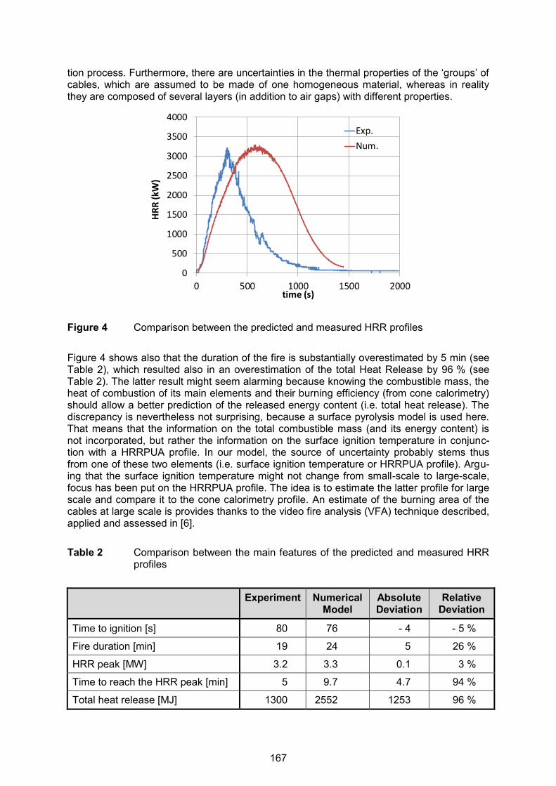
tion process. Furthermore, there are uncertainties in the thermal properties of the ‘groups’ of cables, which are assumed to be made of one homogeneous material, whereas in reality they are composed of several layers (in addition to air gaps) with different properties.
Figure 4 Comparison between the predicted and measured HRR profiles Figure 4 shows also that the duration of the fire is substantially overestimated by 5 min (see Table 2), which resulted also in an overestimation of the total Heat Release by 96 % (see Table 2). The latter result might seem alarming because knowing the combustible mass, the heat of combustion of its main elements and their burning efficiency (from cone calorimetry) should allow a better prediction of the released energy content (i.e. total heat release). The discrepancy is nevertheless not surprising, because a surface pyrolysis model is used here. That means that the information on the total combustible mass (and its energy content) is not incorporated, but rather the information on the surface ignition temperature in conjunc-tion with a HRRPUA profile. In our model, the source of uncertainty probably stems thus from one of these two elements (i.e. surface ignition temperature or HRRPUA profile). Argu-ing that the surface ignition temperature might not change from small-scale to large-scale, focus has been put on the HRRPUA profile. The idea is to estimate the latter profile for large scale and compare it to the cone calorimetry profile. An estimate of the burning area of the cables at large scale is provides thanks to the video fire analysis (VFA) technique described, applied and assessed in [6]. Table 2 Comparison between the main features of the predicted and measured HRR
profiles
Experiment Numerical Model
Absolute Deviation
Relative Deviation
Time to ignition [s] 80 76 - 4 - 5 %
Fire duration [min] 19 24 5 26 %
HRR peak [MW] 3.2 3.3 0.1 3 %
Time to reach the HRR peak [min] 5 9.7 4.7 94 %
Total heat release [MJ] 1300 2552 1253 96 %
0
500
1000
1500
2000
2500
3000
3500
4000
0 500 1000 1500 2000
HR
R (
kW)
time (s)
Exp.
Num.
167

The temporal evolution of the cables’ burning area is illustrated in Figure 5. Dividing the large-scale HRR profile by the burning area (see Figure 5) allows having an estimate of the large scale HRRPUA profile, which is displayed in Figure 6 and compared to its counterpart for the small scale. One can see that: (1) the average steady-state HRRPUA value for the large-scale is slightly lower than the small scale, and (2) the decay stage starts much earlier for the large-scale. As a consequence, strong deviations are obtained when transposing the HRRPUA profile from small-scale to large-scale. Other elements of uncertainty are worth mentioning, such as (i) the possible shrinkage in the cable area due to burning (which is not accounted for here), or (ii) the contact surface between the cables (despite the ‘loose’ ar-rangement) that reduces the burning area (also not accounted for here). It is important to note that these uncertainties confer to the calculation a rather conservative aspect (i.e. over-estimation of the total heat release) except at the early stage where the predicted fire growth rate is lower than the actual one.
Figure 5 Estimated temporal profile of cable burning area from video fire analysis (VFA)
Figure 6 Comparison between the measured small-scale and large-scale HRRPUA
168
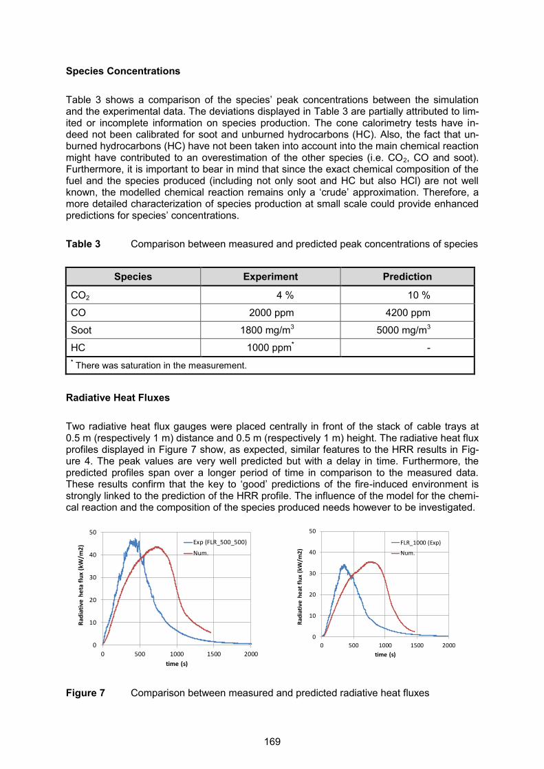
Species Concentrations Table 3 shows a comparison of the species’ peak concentrations between the simulation and the experimental data. The deviations displayed in Table 3 are partially attributed to lim-ited or incomplete information on species production. The cone calorimetry tests have in-deed not been calibrated for soot and unburned hydrocarbons (HC). Also, the fact that un-burned hydrocarbons (HC) have not been taken into account into the main chemical reaction might have contributed to an overestimation of the other species (i.e. CO2, CO and soot). Furthermore, it is important to bear in mind that since the exact chemical composition of the fuel and the species produced (including not only soot and HC but also HCl) are not well known, the modelled chemical reaction remains only a ‘crude’ approximation. Therefore, a more detailed characterization of species production at small scale could provide enhanced predictions for species’ concentrations. Table 3 Comparison between measured and predicted peak concentrations of species
Species Experiment Prediction
CO2 4 % 10 %
CO 2000 ppm 4200 ppm
Soot 1800 mg/m3 5000 mg/m3
HC 1000 ppm* - * There was saturation in the measurement.
Radiative Heat Fluxes Two radiative heat flux gauges were placed centrally in front of the stack of cable trays at 0.5 m (respectively 1 m) distance and 0.5 m (respectively 1 m) height. The radiative heat flux profiles displayed in Figure 7 show, as expected, similar features to the HRR results in Fig-ure 4. The peak values are very well predicted but with a delay in time. Furthermore, the predicted profiles span over a longer period of time in comparison to the measured data. These results confirm that the key to ‘good’ predictions of the fire-induced environment is strongly linked to the prediction of the HRR profile. The influence of the model for the chemi-cal reaction and the composition of the species produced needs however to be investigated.
Figure 7 Comparison between measured and predicted radiative heat fluxes
0
10
20
30
40
50
0 500 1000 1500 2000
Rad
iati
ve h
eta
flu
x (k
W/m
2)
time (s)
Exp (FLR_500_500)
Num.
0
10
20
30
40
50
0 500 1000 1500 2000
Rad
iati
ve h
eat
flu
x (k
W/m
2)
time (s)
FLR_1000 (Exp)
Num.
169
CONCLUSIONS AND FUTURE WORK The aim of the work presented here was to perform and assess a fully predictive CFD simu-lation of a large-scale fire involving a stack of horizontal cable trays. The methodology is mainly based on a surface pyrolysis model that relies upon the specifi-cation of a ‘surface ignition temperature’ in conjunction with a temporal profile of HRRPUA. This information for the set of cables, specific to the large scale test considered in this work, is obtained from small-scale laboratory tests. Since the heat-up and ignition of the large number of cables in the large-scale cannot be modelled on an individual basis (i.e. cable by cable) due to limitations in the computational resources, the arrangement in the CFD model has been set in terms of ‘groups’ of cables. The dimensions of the ‘groups’ of cables have been set to yield an overall cable surface area (i.e. cumulative perimeter of the cables) equivalent to the actual configuration. Furthermore, the ‘groups’ of cables were separated by small interstices, in an attempt to mimic the actual pattern of the fire spread according to which flames and hot gas penetrate through the cable trays in a vertical direction before starting to spread radially. An additional modelling point discussed in this work is the set-up of the chemical reaction. The several valuable small-scale tests did not allow a full character-ization of the species produced from the burning of the cables (made mainly of PVC and a plasticizer), inducing therefore an additional source of uncertainty. The results obtained are quite encouraging, particularly for the peak heat release rate (HRR) which was predicted with a relative deviation of 3 %. The time to reach the peak is however overestimated by 4.7 min (i.e. 94 %). The fire duration is also overestimated by 5 min (i.e. 24 %). These discrepancies are mainly attributed to differences in the HRRPUA (heat re-lease per unit area) profiles between small-scale and large-scale. The latter was calculated by estimating the burning area of cables using video fire analysis (VFA). There are also oth-er elements of uncertainty worth mentioning, such as (i) the possible shrinkage in the cable area due to burning (which is not accounted for here), or (ii) the contact surface between the cables (despite the ‘loose’ arrangement) that reduces the burning area (also not accounted for here). The results in terms of radiative heat fluxes were similar to the HRR results. How-ever, larger discrepancies are obtained for the concentration of species, which could be mainly attributed to uncertainties in the yields of species produced (such as HCl and un-burned hydrocarbons, which were not quantified and therefore not considered in the single-step chemical reaction). Future work will be performed to assess the overall level of uncertainties by performing simulations with different options for (1) the set-up of the chemical reaction, (2) the choice of the overall thermal properties of the ‘groups’ of cables, and possibly (3) alternative geomet-rical arrangements. The methodology will also be applied and evaluated for additional large-scale tests. ACKNOWLEDGMENTS The research carried out in this work has mainly been funded by Bel V through a post-doctoral research grant (contract number A12/TT/0617). The authors are also grateful for the financial support of the participating OECD/NEA member countries (Belgium, Canada, Fin-land, France, Germany, Japan, Spain, Sweden, United Kingdom) to the joint OECD PRISME 2 project. Thanks also to Prof. Simo Hostikka (Aalto University, Finland) and Dr. Anna Matala (VTT, Finland) for providing us with the cone calorimetry data. Dr. Tarek Beji is Postdoctoral Fellow of the Fund of Scientific Research – Flanders (Belgium) (FWO-Vlaanderen).
170
REFERENCES [1] Audouin, L., et al., “OECD PRISME Project: Fires in confined and ventilated nuclear-
type multi-compartments - Overview and main experimental results”, Fire Safety Jour-nal, Volume 62, November 2013, pp. 80-101, doi:10.1016/j.firesaf.2013.07.008.
[2] Audouin, L., H. Prétrel, P. Zavaleta, “OECD PRISME 2 Fire Research Project (2011-2016) – Current Status and Perspectives”, in: Röwekamp, M., H.-P. Berg (Eds.): Proceedings of SMiRT 22, 13th International Seminar on Fire Safety in Nuclear Power Plants and Installations, September 18-20, 2013, Columbia, SC, USA, GRS-A-3731, Gesellschaft für Anlagen- und Reaktorsicherheit (GRS) mbH, Köln, Germany, Decem-ber 2013, http://www.grs.de/sites/default/files/pdf/grs-a-3731.pdf.
[3] Zavaleta, P., et al., “Multiple Horizontal Cable Tray Fire in Open Atmosphere”, in: Fire and Materials, Thirteenth international conference, San Francisco, CA, USA, 28th – 30th January, 2013, interscience communications, London, UK, 2013, pp. 57-68, http://www.intersciencecomms.co.uk/html/publications/f&m13toc.pdf.
[4] Mangs, J., S. Hostikka, Experimental characterization of the MCMK cable for fire safety assessment, Research Report VTT-R-06873-12, VTT, Espoo, Finland, 2013, http://www.vtt.fi/inf/julkaisut/muut/2012/VTT-R-06873-12.pdf.
[5] Electric Power Research Institute (EPRI) and United States Nuclear Regulatory Com-mission Office of Nuclear Research (NRC-RES), Fire PRA Methodology for Nuclear Power Facilities, EPRI/NRC-RES, Final Report, Volume 2: Detailed Methodology, EPRI 1011989, NUREG/CR-6850, Palo Alto, CA, USA, September 2005, http://www.nrc.gov/reading-rm/doc-collections/nuregs/contract/cr6850/v2/cr6850v2.pdf.
[6] Beji, T., et al., “Flame Spread Monitoring and Estimation of the Heat Release Rate from a Cable Tray Fire Using Video Fire Analysis (VFA)”, in: Proceedings of the 2nd IAFSS European Symposium of Fire Safety Science, Cyprus, 16-18 June 2015, ISBN: 978-9963-2177-0-0, http://www.iafss.org/2nd-european-symposium-of-fire-safety-science/.
[7] Hunter, L. W., “Models of horizontal electric cables and cable trays exposed to a fire plume”, Combustion and Flame, Volume 35, 1979, pp. 311-322, http://www.sciencedirect.com/science/journal/00102180/35.
[8] Askit, I. M,. J. B. Moss, P. A. Rubini, “CFD simulation of cable tray fires”, in: Proceedings of the Ninth International Conference – INTERFLAM 2001, interscience communications, London, UK, pp. 1129-1140, 2001, ISBN 0-9532312-7, http://www.shop.intersciencecomms.co.uk/publications/products.asp?cat=10.
[9] Matala, A., S. Hostikka, “Probabilistic simulation of cable performance and water based protection in cable tunnel fires”, Nuclear Engineering and Design, Volume 241, Issue 12, 2011, pp. 5263-5274, http://www.sciencedirect.com/science/article/pii/S0029549311008077.
[10] Drysdale, D., An Introduction to Fire Dynamics, John Wiley and Sons Ltd., United King-dom, August 2011, http://eu.wiley.com/WileyCDA/WileyTitle/productCd-EHEP002263.html.
[11] Tewarson, A., “Generation of Heat and Chemical Compounds in Fires”, in: DiNenno, P. J. (Ed.), SFPE Handbook of Fire Protection Engineering, Third Edition, Section 3, Chapter 3-4, Quincy, MA 02269, USA, 2002.
[12] McGrattan, K., et al., Fire Dynamics Simulator, User’s Guide, NIST Special Publication 1019, Sixth Edition, National Institute of Standards and Technology (NIST), Gaithersburg, MD, USA, November 2013, http://www.thunderheadeng.com/wp-content/uploads/2013/08/FDS_User_Guide.pdf.
171

23nd International Conference on Structural Mechanics in Reactor Technology (SMiRT 23) - 14th
International Post-Conference Seminar on “FIRE SAFETY IN NUCLEAR POWER PLANTS AND INSTALLATIONS“
EXPERIMENTAL AND NUMERICAL STUDY OF SMOKE PROPAGATION THROUGH A VENT SEPARATING TWO
MECHANICALLY VENTILATED ROOMS
Laurent Audouin, Hugues PRETREL, Samuel Vaux
Institut de Radioprotection et de Sûreté Nucléaire (IRSN), Centre de Cadarache - Bât 346 - 13 115 Saint Paul Lez Durance, France
ABSTRACT The paper presents an experimental and numerical study about smoke propagation through a horizontal opening between two superposed compartments, as can be encountered in nu-clear installations, in case of a fire taking place in the lower room. The experimental configu-ration proposed in this study consists in two rooms mechanically ventilated and connected each other by a horizontal opening. The fire source is simulated by a propane burner located in the lower room. The inlet ventilation duct is located in the lower room and the exhaust ventilation duct is located in the upper room. For such experimental configuration, several flow regimes at the horizontal opening connecting the two rooms can be encountered de-pending on the fire power, the opening size (diameter, depth) and the ventilation set-up (lo-cation of inlet/outlet ducts, flow rate). Indeed, flow at the opening is governed by buoyant forces due to the hot gases produced by the fire, the inertia effect due to the forced ventila-tion and the momentum effect due to smoke flow nearby the horizontal opening (for in-stance, ceiling jet or thermal plume from fire). Consequently, such complex mixed (natu-ral/forced) convective flows are still a challenge for CFD fire codes to make properly calcula-tions of these experimental scenarios. The objective of this paper is to assess the capability of ISIS code (CFD) to simulate the behaviour of smoke propagation inside these two super-posed compartments. Results of this study are presented with details (especially, thermal stratification and flow rates through the horizontal vent) and are discussed thoroughly. INTRODUCTION Smoke movement in nuclear installations is a major issue for safety assessments. Indeed, due to the transport of hot gases and soot particles from the initial fire room to neighbouring compartments, safety systems (i.e. EIS, Equipment Important for Safety) can be damaged as clogging of high efficiency filters (HEPA) located in the ventilation network or failure of electrical or electronic devices. Smoke can flow through horizontal or vertical openings (for example, doorways, vents or reduced orifices used for running cables) controlling the mass and heat transfer of hot gases between compartments. As the nuclear facilities are equipped with a ventilation network, these flows are governed by mixed convection (both buoyancy and inertia), are often mono or bidirectional and turbulent in nature. When the opening is di-rectly connected to the fire enclosure, the flow may have a significant effect on the evolution of fire source by modifying the amount of air (and consequently of oxygen) entering into the enclosure and the exhaust of combustion products to adjacent rooms. Thus, predicting such flows from engineering zone codes and CFD tools remains a key issue for nuclear safety as-sessments. From this challenge, this study proposes to focus especially on the heat and mass transfer of hot gases through a horizontal opening separating two superposed com-partments. A brief overview of the literature [1] to [6] shows that previous experimental studies have es-tablished the theoretical basis of such vertical flows. From small-scale experiments, these
172

2
authors proposed some analytical approaches to calculate the natural flows due to buoyant effect based on the Froude number as well as the inertia term when mechanical ventilation is applied. From these approaches and the corresponding database, Cooper [4], [5] has pro-posed correlations in order to determine flowrate for pure natural convection and mixed con-vection in the goal of being used in zone codes. However, there are very few experimental studies focusing on this type of smoke flow and the Cooper models, which are used in most fire zone codes, have been validated only on very limited number of experiments (mainly at small scale). Thus, their predictive performances are still discussed, especially for large scale fire tests and for confined and mechanically ventilated enclosures as pointed out by Emmons [6] and Li [7]. Consequently, it is worth to investigate further for experimental and theoretical studies concerning vertical flows through horizontal openings based on large-scale tests including the effect of forced flow. The expected outcomes are to improve the physical understanding of these types of flows with variable density, to validate/enhance the existing correlations and to assess the CFD codes to simulate such flows. This study investigates the capability of CFD code developed in IRSN [8], [10] to capture the main behaviour of mixed convective flow (natural/forced) through a horizontal opening sepa-rating two superposed rooms during large-scale fire tests carried out in IRSN experimental installation. In this work, an engineer approach is used with the CFD code, as a first step. In order to assess the relative effect of natural convection due to thermal plume vs forced flow induced by the ventilation system, two initial regimes of forced ventilation are more especial-ly investigated in this paper for a constant heat release rate of 97 kW: (1) high ventilation rate (i.e. about 2300 m3/h) and (2) low ventilation rate (i.e. about 600 m3/h). DESCRIPTION OF THE FACILITY AND EXPERIMENTS The DIVA Facility The IRSN DIVA experimental facility is a large scale multi-room facility (see Figure 1 and 0) representative of nuclear installations. It includes four compartments (labelled 1 to 4) and a corridor. All the walls are 0.3 m thick and are built with reinforced concrete designed to with-stand a gas pressure ranging from – 100 hPa to 520 hPa. The compartments labelled 1 to 3 are 6 m in length, 5 m in width and 4 m in height.
Figure 1 Schematic of the DIVA facility and its ventilation network
Figure 2 Main geometrical dimen-sions of the DIVA facility
The room 4 (length × width × height = 8.8 × 5 × 4 m3) is designed to study the vertical hot gas propagation from a lower (room 3) to an upper room (room 4) through a horizontal open-
ROOM 1ROOM 1
CORRIDOR
CORRIDOR
ROOM 2ROOM 2
ROOM 3ROOM 3
ROOM 4ROOM 4
4 m
4 m
5 m
5 m
5 m 6 m2.5 m
ROOM 1ROOM 1
CORRIDOR
CORRIDOR
ROOM 2ROOM 2
ROOM 3ROOM 3
ROOM 4ROOM 4
4 m
4 m
5 m
5 m
5 m 6 m2.5 m
173

ing having a surface of about 1 m². The corridor (length × width × height = 15 × 2.5 × 4 m3) is located along the rooms 1 to 3. All rooms of the DIVA facility can be connected with a mechanical ventilation system by means of inlet and outlet ducts, which can be set up at any height in each room depending of the fire scenarios. The lower rooms (compartments 1 to 3 and corridor) can be connected through a single doorway or different types of elements (simple openings, fire door, etc.). The DIVA installation can be highly instrumented (up to 800 possible measurement channels on the data acquisition system) and its ventilation network allowed it to simulate ventilation configurations representative of NPP (Nuclear Power Plant) as well as nuclear laboratories and nuclear reprocessing plant. For this study, the aim is to investigate the vertical smoke propagation through a horizontal opening (or hopper) for mechanically ventilated fire room scenarios. The tests are focused on the study of the flows going through the vent. Indeed, these types of flows are complex in nature (typically, mono or bi-directional) because of the competition between the buoyancy force due to the density difference on one hand and, on the other hand, the inertia force due to the relative pressure induced by the ventilation system. Moreover, the flows could be sig-nificantly more complex if fire plume is located just below through the hopper (i.e. including the direct effect of plume momentum). The fire scenario in Figure 3 for the two tests studied in this paper comprises two rooms with mechanical ventilation (one lower compartment as fire room, i.e. room 3; one upper room, i.e. room 4, connected by a horizontal opening of 1m² in area). The inlet duct of fire room and the outlet duct of upper compartment (or target room) are located in the upper part of each compartment (about 0.8 m from the ceiling).
Figure 3 Experimental configuration The walls are made in re-enforced concrete, of which some areas are covered with 30 mm rock-wool panels for safety requirements. The wall areas are the ceiling of both rooms and the upper parts (about 2 m) of the side walls in the fire room. The horizontal vent is a rectangular section with the dimensions 1.03 m × 1.03 m = 1.06 m2, located at the centre of the fire room (off-centre in the upper room, as shown in 0 b)). The overall depth of the orifice is 0.385 m, which corresponds to the 0.300 mm thickness of the concrete wall separating the two rooms and a layer of rock wool. Fire Source
The fire source (cf. Figure 4) is a rectangular propane gas burner (with an equivalent diame-ter of 1.13 m) located at the Northwest corner of the lower room (off-centre location). The
BUOYANCY (∆T) INERTIA
(∆P)MOMENTUM
(U)
174
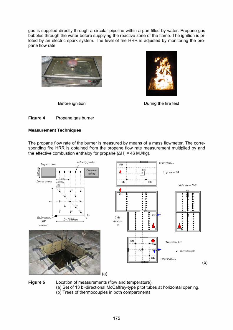
gas is supplied directly through a circular pipeline within a pan filled by water. Propane gas bubbles through the water before supplying the reactive zone of the flame. The ignition is pi-loted by an electric spark system. The level of fire HRR is adjusted by monitoring the pro-pane flow rate.
Before ignition
During the fire test
Figure 4 Propane gas burner Measurement Techniques
The propane flow rate of the burner is measured by means of a mass flowmeter. The corre-sponding fire HRR is obtained from the propane flow rate measurement multiplied by and the effective combustion enthalpy for propane (∆Hc = 46 MJ/kg).
(a)
(b)
Figure 5 Location of measurements (flow and temperature): (a) Set of 13 bi-directional McCaffrey-type pitot tubes at horizontal opening, (b) Trees of thermocouples in both compartments
Top view L4
Top view L3
Sideview E-
W
Side view N-S
SW
NESE
CC
SWNW
CC
NE
1250*2120mm
1250*1500mm
Thermocouple
175
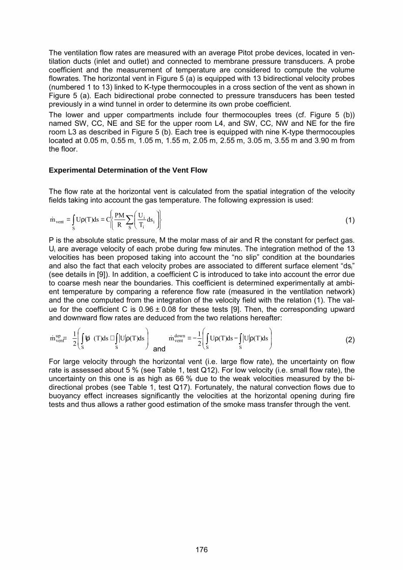
The ventilation flow rates are measured with an average Pitot probe devices, located in ven-tilation ducts (inlet and outlet) and connected to membrane pressure transducers. A probe coefficient and the measurement of temperature are considered to compute the volume flowrates. The horizontal vent in Figure 5 (a) is equipped with 13 bidirectional velocity probes (numbered 1 to 13) linked to K-type thermocouples in a cross section of the vent as shown in Figure 5 (a). Each bidirectional probe connected to pressure transducers has been tested previously in a wind tunnel in order to determine its own probe coefficient. The lower and upper compartments include four thermocouples trees (cf. Figure 5 (b)) named SW, CC, NE and SE for the upper room L4, and SW, CC, NW and NE for the fire room L3 as described in Figure 5 (b). Each tree is equipped with nine K-type thermocouples located at 0.05 m, 0.55 m, 1.05 m, 1.55 m, 2.05 m, 2.55 m, 3.05 m, 3.55 m and 3.90 m from the floor. Experimental Determination of the Vent Flow The flow rate at the horizontal vent is calculated from the spatial integration of the velocity fields taking into account the gas temperature. The following expression is used:
=ρ= ∑∫
Si
i
i
Svent ds
TU
RPMCds)T(Um&
(1)
P is the absolute static pressure, M the molar mass of air and R the constant for perfect gas. Ui are average velocity of each probe during few minutes. The integration method of the 13 velocities has been proposed taking into account the “no slip” condition at the boundaries and also the fact that each velocity probes are associated to different surface element “dsi” (see details in [9]). In addition, a coefficient C is introduced to take into account the error due to coarse mesh near the boundaries. This coefficient is determined experimentally at ambi-ent temperature by comparing a reference flow rate (measured in the ventilation network) and the one computed from the integration of the velocity field with the relation (1). The val-ue for the coefficient C is 0.96 ± 0.08 for these tests [9]. Then, the corresponding upward and downward flow rates are deduced from the two relations hereafter:
ρ+ρ= ∫∫ ds)T(Uds)T(U
21m
SS
upvent&
and
ρ−ρ−= ∫∫ ds)T(Uds)T(U
21m
SS
downvent&
(2)
For large velocity through the horizontal vent (i.e. large flow rate), the uncertainty on flow rate is assessed about 5 % (see Table 1, test Q12). For low velocity (i.e. small flow rate), the uncertainty on this one is as high as 66 % due to the weak velocities measured by the bi-directional probes (see Table 1, test Q17). Fortunately, the natural convection flows due to buoyancy effect increases significantly the velocities at the horizontal opening during fire tests and thus allows a rather good estimation of the smoke mass transfer through the vent.
176

Table 1 Initial experimental conditions for the two tests
Test Q12 Test Q17
HRR [kW] 97 97
Tr [1/h] (*) 8.0 2.2
Before ignition (experimental values)
Q adm (fire room) [m3/h] 2270 630
Q ext (target room) [m3/h] 2380 680
Q net [m3/h] 2205 225
Q(FR -> TR) [m3/h] 2250 365
Q(TR -> FR) [m3/h] 45 140
Uncertainty [%] ∼ 5 ∼ 66 * The renewal rate Tr is computed as the ratio between the volume flow rate in inlet duct before ignition and the
room volume.
Experimental Procedure During Fire Tests The test procedure is as follows: First, the ventilation network is put into place in order to achieve the expected ventilation flow rate. Then, the gas burner is turned on. A mixed con-vection flow starts to occur at the horizontal vent, and smoke progressively fills up the adja-cent compartment. The fire HRR remains constant over all the test duration. The test is stopped (i.e. the gas burner is turned off) once a quasi-steady state is obtained. The criteria are based on the velocity and gas temperature recordings at the vent and the vertical tem-perature stratification within the two rooms. NUMERICAL MODELLING Model Overview A detailed description of the ISIS code (CFD code) is out of the scope of this paper and is available with more details in [8], [10], and [11]. The physical modelling used in ISIS is based on the low-Mach number assumption. As a result, the thermodynamic pressure in confined environments is constant in space but varies in time. Turbulence modelling is dealt with the Favre-averaging approach. The turbulent terms describing the Reynolds stress tensor and turbulent scalar fluxes are modelled using the eddy viscosity hypothesis and the standard k-ε model with usual wall laws (i.e. logarithmic law). Turbulent combustion is based on the fast chemistry conserved scalar approach and the mean reaction rate, which is controlled by the turbulent flow mixing, is determined by the Eddy-Dissipation Concept model (EDC). A one-step irreversible chemistry is assumed. The soot production and oxidation are simulated by a semi-empirical one equation model and radiative transfers are dealt with P1 radiative model. The gas absorption coefficient of the mixture used the total emissivity approach of the Weighted Sum of Gray Gases model and the soot absorption coefficient is related to the soot volume fraction (scattering effects are neglected according to the Mie theory). The wall conduction is taken into account through the 1D Fourier’s equation and the convective flux is given by standard thermal wall laws. The mass flow rate of the ventilation network at each branch of the compartment is solved using a general Bernoulli equation.
177
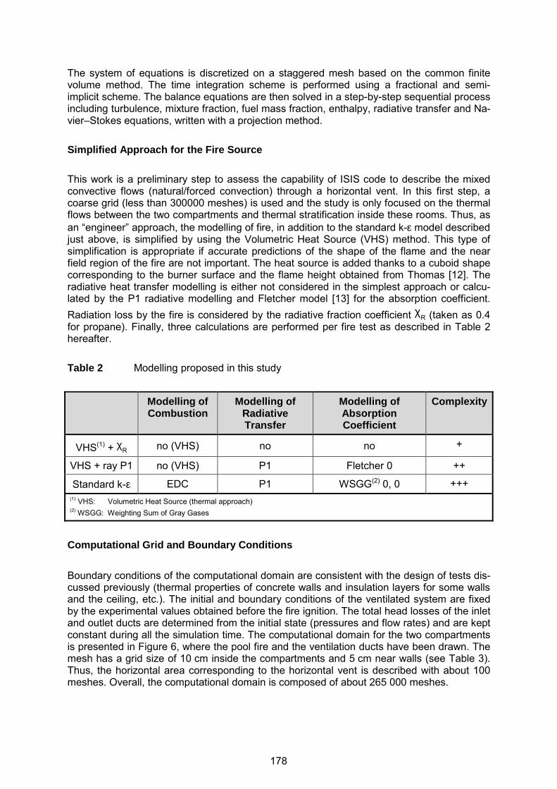
The system of equations is discretized on a staggered mesh based on the common finite volume method. The time integration scheme is performed using a fractional and semi-implicit scheme. The balance equations are then solved in a step-by-step sequential process including turbulence, mixture fraction, fuel mass fraction, enthalpy, radiative transfer and Na-vier–Stokes equations, written with a projection method. Simplified Approach for the Fire Source This work is a preliminary step to assess the capability of ISIS code to describe the mixed convective flows (natural/forced convection) through a horizontal vent. In this first step, a coarse grid (less than 300000 meshes) is used and the study is only focused on the thermal flows between the two compartments and thermal stratification inside these rooms. Thus, as an “engineer” approach, the modelling of fire, in addition to the standard k-ε model described just above, is simplified by using the Volumetric Heat Source (VHS) method. This type of simplification is appropriate if accurate predictions of the shape of the flame and the near field region of the fire are not important. The heat source is added thanks to a cuboid shape corresponding to the burner surface and the flame height obtained from Thomas [12]. The radiative heat transfer modelling is either not considered in the simplest approach or calcu-lated by the P1 radiative modelling and Fletcher model [13] for the absorption coefficient. Radiation loss by the fire is considered by the radiative fraction coefficient χR (taken as 0.4 for propane). Finally, three calculations are performed per fire test as described in Table 2 hereafter. Table 2 Modelling proposed in this study
Modelling of Combustion
Modelling of Radiative Transfer
Modelling of Absorption Coefficient
Complexity
VHS(1) + χR no (VHS) no no +
VHS + ray P1 no (VHS) P1 Fletcher 0 ++
Standard k-ε EDC P1 WSGG(2) 0, 0 +++ (1) VHS: Volumetric Heat Source (thermal approach) (2) WSGG: Weighting Sum of Gray Gases
Computational Grid and Boundary Conditions
Boundary conditions of the computational domain are consistent with the design of tests dis-cussed previously (thermal properties of concrete walls and insulation layers for some walls and the ceiling, etc.). The initial and boundary conditions of the ventilated system are fixed by the experimental values obtained before the fire ignition. The total head losses of the inlet and outlet ducts are determined from the initial state (pressures and flow rates) and are kept constant during all the simulation time. The computational domain for the two compartments is presented in Figure 6, where the pool fire and the ventilation ducts have been drawn. The mesh has a grid size of 10 cm inside the compartments and 5 cm near walls (see Table 3). Thus, the horizontal area corresponding to the horizontal vent is described with about 100 meshes. Overall, the computational domain is composed of about 265 000 meshes.
178
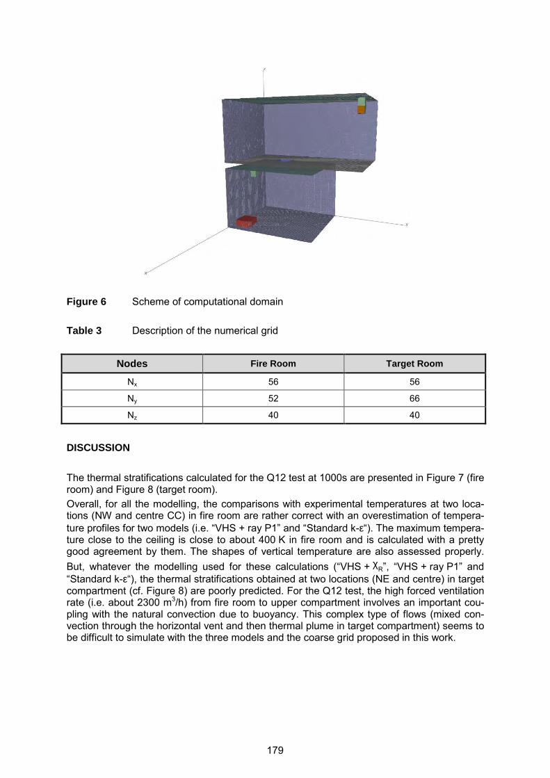
Figure 6 Scheme of computational domain Table 3 Description of the numerical grid
Nodes Fire Room Target Room
Nx 56 56
Ny 52 66
Nz 40 40
DISCUSSION The thermal stratifications calculated for the Q12 test at 1000s are presented in Figure 7 (fire room) and Figure 8 (target room). Overall, for all the modelling, the comparisons with experimental temperatures at two loca-tions (NW and centre CC) in fire room are rather correct with an overestimation of tempera-ture profiles for two models (i.e. “VHS + ray P1” and “Standard k-ε“). The maximum tempera-ture close to the ceiling is close to about 400 K in fire room and is calculated with a pretty good agreement by them. The shapes of vertical temperature are also assessed properly. But, whatever the modelling used for these calculations (“VHS + χR”, “VHS + ray P1” and “Standard k-ε“), the thermal stratifications obtained at two locations (NE and centre) in target compartment (cf. Figure 8) are poorly predicted. For the Q12 test, the high forced ventilation rate (i.e. about 2300 m3/h) from fire room to upper compartment involves an important cou-pling with the natural convection due to buoyancy. This complex type of flows (mixed con-vection through the horizontal vent and then thermal plume in target compartment) seems to be difficult to simulate with the three models and the coarse grid proposed in this work.
179
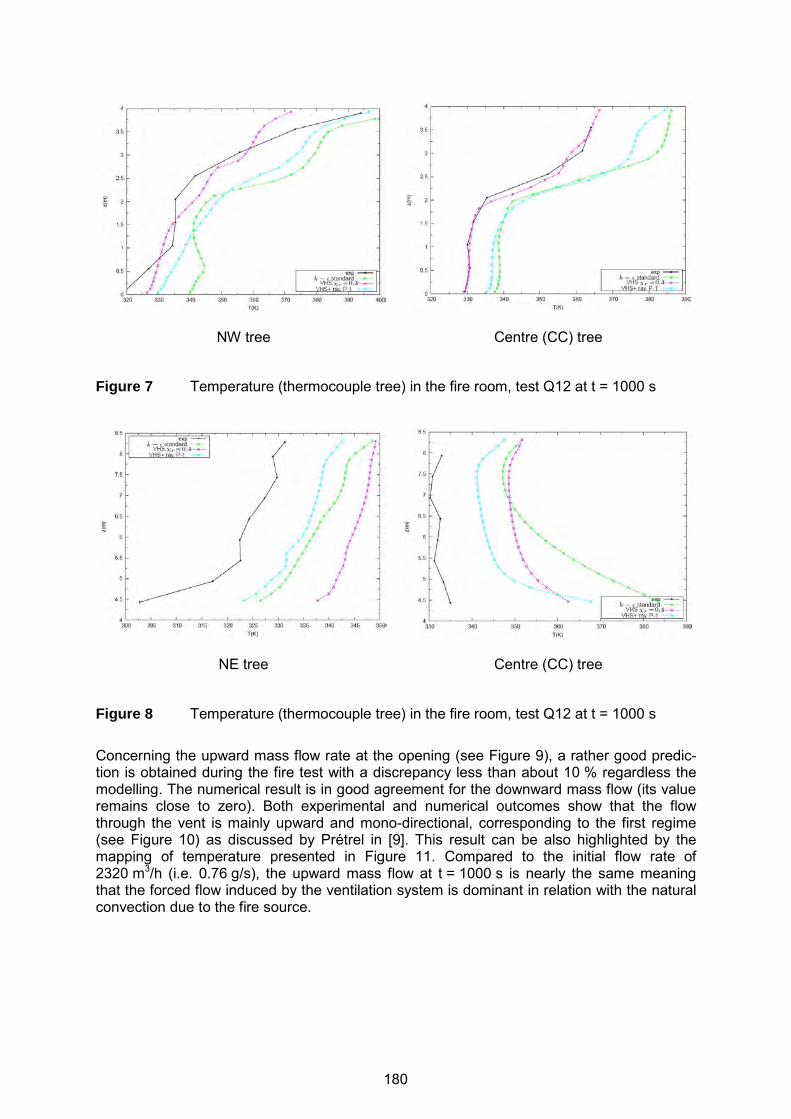
NW tree Centre (CC) tree
Figure 7 Temperature (thermocouple tree) in the fire room, test Q12 at t = 1000 s
NE tree Centre (CC) tree
Figure 8 Temperature (thermocouple tree) in the fire room, test Q12 at t = 1000 s Concerning the upward mass flow rate at the opening (see Figure 9), a rather good predic-tion is obtained during the fire test with a discrepancy less than about 10 % regardless the modelling. The numerical result is in good agreement for the downward mass flow (its value remains close to zero). Both experimental and numerical outcomes show that the flow through the vent is mainly upward and mono-directional, corresponding to the first regime (see Figure 10) as discussed by Prétrel in [9]. This result can be also highlighted by the mapping of temperature presented in Figure 11. Compared to the initial flow rate of 2320 m3/h (i.e. 0.76 g/s), the upward mass flow at t = 1000 s is nearly the same meaning that the forced flow induced by the ventilation system is dominant in relation with the natural convection due to the fire source.
180
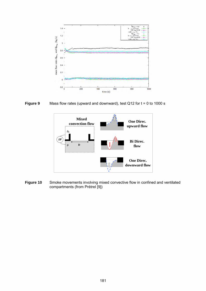
Figure 9 Mass flow rates (upward and downward), test Q12 for t = 0 to 1000 s
Figure 10 Smoke movements involving mixed convective flow in confined and ventilated
compartments (from Prétrel [9])
One Direc. upward flow
∆P
ρ D
2ReGr
P
DgB =
∆∆= ρ
ρ0
Mixed convection flow
Bi Direc. flow
One Direc. downward flow
181

Figure 11 Temperature mapping (ISIS simulation) with “k-ε standard” modelling Test Q12 at t = 1000s
The thermal stratifications assessed by the CFD code for the Q17 test at 1000 s are pre-sented in Figure 12 (lower room) and in Figure 13 (upper room). Compared with the previous simulation of Q12 test, the vertical temperatures (values and shapes) at the two same loca-tions as previously are in good agreement with experimental data for the two models taking into account the radiative heat transfer, namely “VHS + ray P1” and “Standard k-ε“. The modelling “VHS + χR” does however not calculate the temperature profiles both in fire and target compartments properly. Indeed, the temperatures inside rooms are widely overesti-mated whatever the height considered.
NW tree Centre (CC) tree
Figure 12 Temperature (thermocouple tree) in the fire room, test Q17 at t = 1000 s
T [°C]
407 (135°C) 324 (50°C)
182
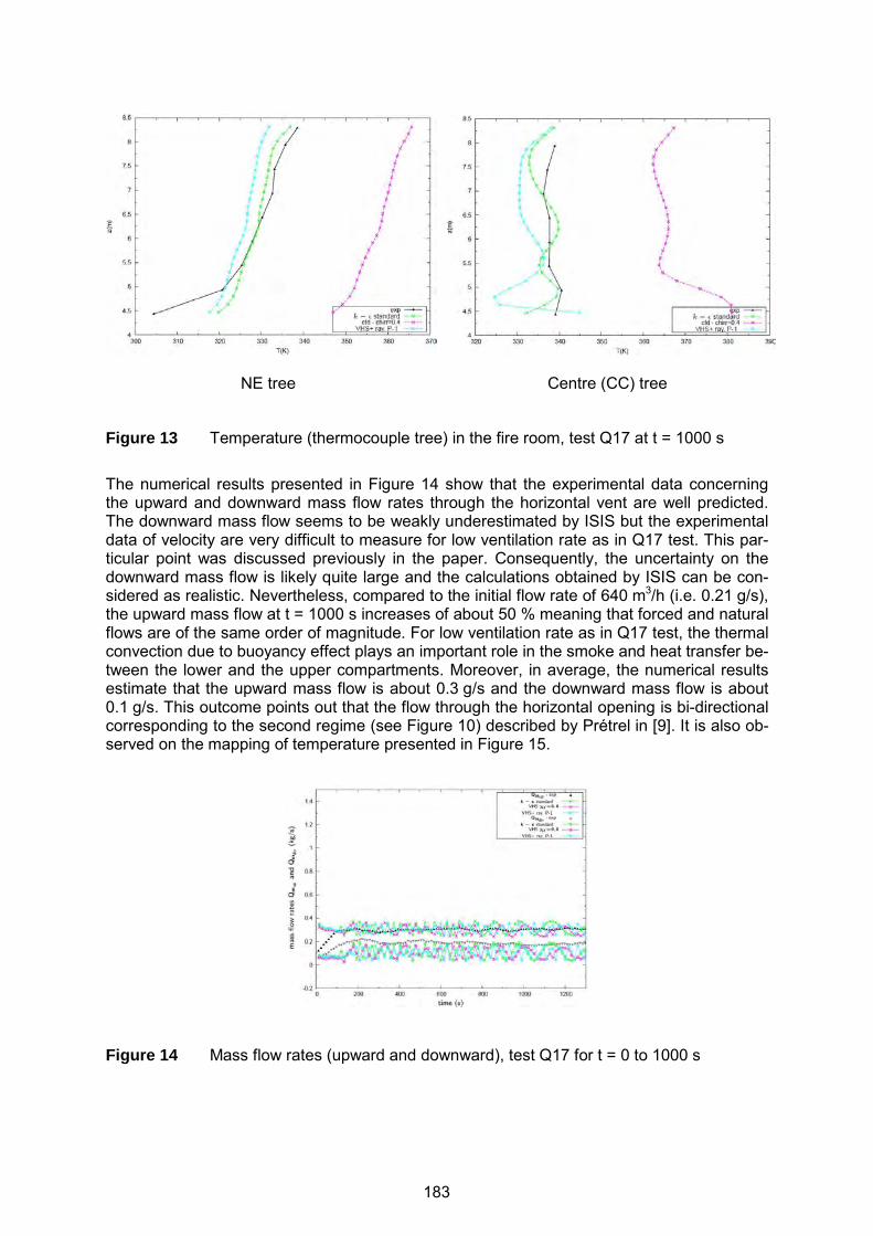
NE tree Centre (CC) tree
Figure 13 Temperature (thermocouple tree) in the fire room, test Q17 at t = 1000 s The numerical results presented in Figure 14 show that the experimental data concerning the upward and downward mass flow rates through the horizontal vent are well predicted. The downward mass flow seems to be weakly underestimated by ISIS but the experimental data of velocity are very difficult to measure for low ventilation rate as in Q17 test. This par-ticular point was discussed previously in the paper. Consequently, the uncertainty on the downward mass flow is likely quite large and the calculations obtained by ISIS can be con-sidered as realistic. Nevertheless, compared to the initial flow rate of 640 m3/h (i.e. 0.21 g/s), the upward mass flow at t = 1000 s increases of about 50 % meaning that forced and natural flows are of the same order of magnitude. For low ventilation rate as in Q17 test, the thermal convection due to buoyancy effect plays an important role in the smoke and heat transfer be-tween the lower and the upper compartments. Moreover, in average, the numerical results estimate that the upward mass flow is about 0.3 g/s and the downward mass flow is about 0.1 g/s. This outcome points out that the flow through the horizontal opening is bi-directional corresponding to the second regime (see Figure 10) described by Prétrel in [9]. It is also ob-served on the mapping of temperature presented in Figure 15.
Figure 14 Mass flow rates (upward and downward), test Q17 for t = 0 to 1000 s
183
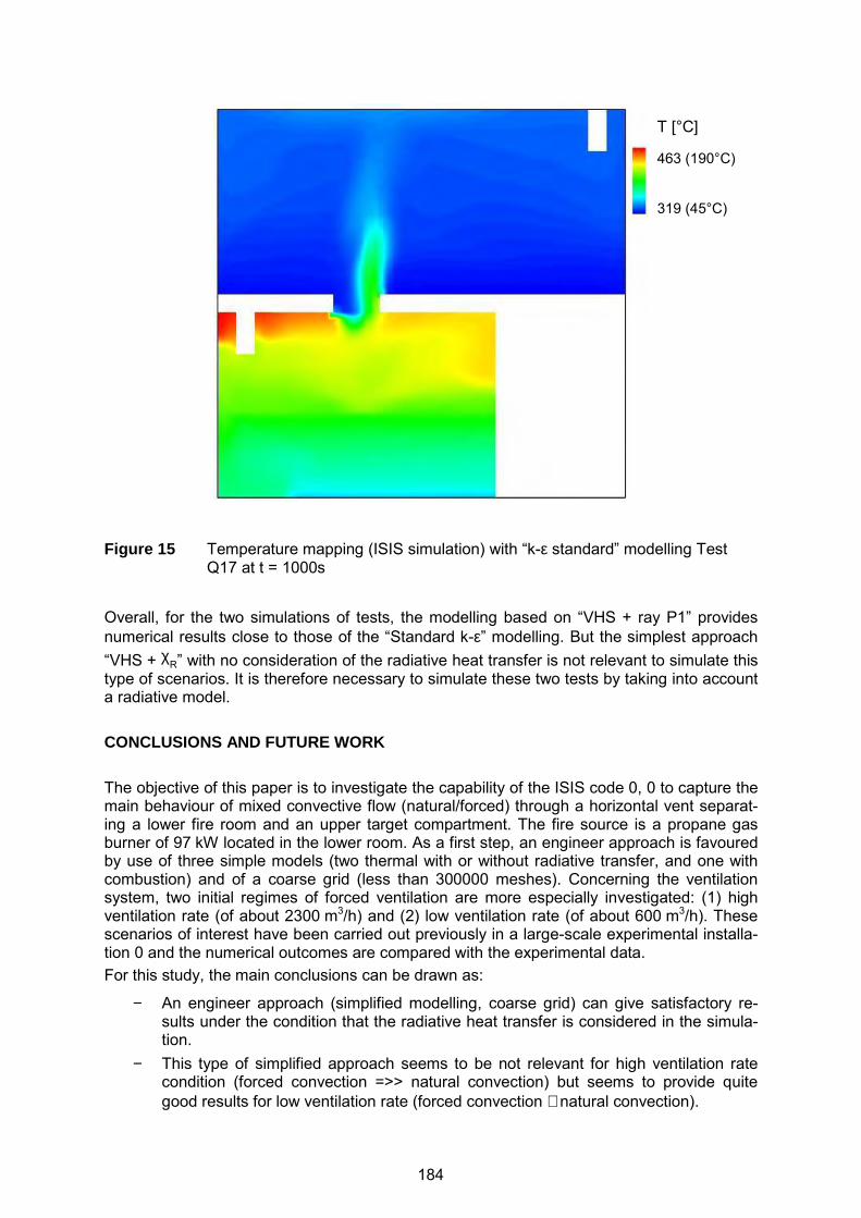
Figure 15 Temperature mapping (ISIS simulation) with “k-ε standard” modelling Test Q17 at t = 1000s
Overall, for the two simulations of tests, the modelling based on “VHS + ray P1” provides numerical results close to those of the “Standard k-ε” modelling. But the simplest approach “VHS + χR” with no consideration of the radiative heat transfer is not relevant to simulate this type of scenarios. It is therefore necessary to simulate these two tests by taking into account a radiative model. CONCLUSIONS AND FUTURE WORK The objective of this paper is to investigate the capability of the ISIS code 0, 0 to capture the main behaviour of mixed convective flow (natural/forced) through a horizontal vent separat-ing a lower fire room and an upper target compartment. The fire source is a propane gas burner of 97 kW located in the lower room. As a first step, an engineer approach is favoured by use of three simple models (two thermal with or without radiative transfer, and one with combustion) and of a coarse grid (less than 300000 meshes). Concerning the ventilation system, two initial regimes of forced ventilation are more especially investigated: (1) high ventilation rate (of about 2300 m3/h) and (2) low ventilation rate (of about 600 m3/h). These scenarios of interest have been carried out previously in a large-scale experimental installa-tion 0 and the numerical outcomes are compared with the experimental data. For this study, the main conclusions can be drawn as:
− An engineer approach (simplified modelling, coarse grid) can give satisfactory re-sults under the condition that the radiative heat transfer is considered in the simula-tion.
− This type of simplified approach seems to be not relevant for high ventilation rate condition (forced convection =>> natural convection) but seems to provide quite good results for low ventilation rate (forced convection ∼ natural convection).
T [°C]
463 (190°C) 319 (45°C)
184
− For the two tests, the regimes of flow (mono and bi-directional) are properly as-sessed.
− Moreover, the numerical outcomes concerning the upward/downward mass flows are in good agreement with the experimental data.
Based on this first study, the next step will consists to go further in the simulation of these two tests, especially by using finer grids and a better description of turbulent flow (LES mod-elling). It is expected that this step provides better predictions concerning the mixed convec-tive flow at the opening, the thermal stratification in the compartments and the plume above the horizontal vent (upper room). REFERENCES [1] Epstein, M., M. A. Kenton, “Combined Natural Convection and Forced Flow Through
Small Openings in a Horizontal Partition With Special Reference to Flows in Multi-compartment Enclosures”, J. Heat Transfer 111(4), 1989, pp. 980-987.
[2] Heskestad, G., R. D. Spaulding, “Inflow of Air Required at Wall and Ceiling Apertures to Prevent Escape of Fire Smoke”, Fire Safety Science, - Proceedings of the 3rd Interna-tional Symposium, International Association for Fire Safety Science, 1991, pp. 919-928.
[3] Tan, Q., Y. Jaluria, “Mass flow through a horizontal vent in an enclosure due to pressure and density differences”, International Journal of Heat and Mass Transfer, 44, 2001, pp. 1543-1553, http://dx.doi.org/10.1016/S0017-9310(00)00198-8.
[4] Cooper, L. Y., Calculation of the flow through a horizontal ceiling/floor vent, Technical Report, NISTIR 89-4052, National Institute of Standards and Technology (NIST), Gaithersburg, MD, USA, 1989.
[5] Cooper, L. Y., “Calculating Combined Buoyancy- and Pressure-driven Flow Through a Shallow, Horizontal, Circular Vent: Application to a Problem of Steady Burning in a Ceil-ing-vented Enclosure”, Fire Safety Journal, 127, 1996, pp.23-35.
[6] Emmons, H. W., T. Tanaka, “Vent Flows”, SFPE Handbook (4th ed.), National Fire Pro-tection Association (NFPA), Quincy, MA, 02269, USA, 2008, pp. 2-37 to 2-53.
[7] Li, Z., Characteristics of Buoyancy Driven Natural Ventilation through Horizontal Open-ings, PhD Thesis, Aalborg University, Aalborg, Denmark, 2007.
[8] Suard, S., et al., “Numerical simulations of fire-induced doorway flows in a small scale enclosure”, International Journal of Heat and Mass Transfer, 81, 2015, pp.578 – 590.
[9] Prétrel, H., et al., “Smoke flow through a horizontal vent separating two mechanically ventilated rooms from large-scale fire tests”, International Conference on Fire Research and Engineering (Interflam), 2013.
[10] Suard, S., et al., “Verification and validation of a CFD model for simulations of large-scale compartment fires”, Nuclear Engineering and Design, 241 (9), 2011, pp. 3645–3657.
[11] Lapuerta, C., et al., “Validation process of ISIS CFD software for fire simulation”, Nucle-ar Engineering and Design, 253, 2912, pp.367–373.
[12] Thomas, P. H. (1963), “The size of flames from natural fires”, 9th International Symposi-um on Combustion, Combustion Institute, Pittsburgh, PA, USA, 1963, pp.844-859.
[13] Fletcher, D. F., et al., “Numerical simulation of smoke movement from a pool fire in a ventilated tunnel”, Fire Safety Journal, 23, 1994, pp.305-325.
185
23st International Conference on Structural Mechanics in Reactor Technology (SMiRT 23) - 14th
International Post-Conference Seminar on “FIRE SAFETY IN NUCLEAR POWER PLANTS AND INSTALLATIONS“
LARGE EDDY SIMULATION OF A MECHANICALLY VENTILATED COMPARTMENT FIRE FOR NUCLEAR APPLICATIONS
Bao P. Xu1 and Jennifer X. Wen2*
1 Faculty of Energy & Power Engineering, Dalian University of Technology, Dalian, China 2 Warwick FIRE, School of Engineering, University of Warwick, Coventry, United Kingdom ABSTRACT This paper deals with the modelling of a mechanically ventilated compartment fire which is a commonplace in nuclear fire scenarios. An advanced Computational Fluid Dynamics (CFD) field model with a wall conjugate heat transfer treatment is proposed. It simultaneously solves the compartment fire flow and the wall heat conduction. The flow solver is based on the Large Eddy Simulation (LES) based fire simulation solver FireFOAM within the frame of open source CFD code OpenFOAM®. An extended eddy dissipation model is used to calcu-late the chemical reaction rate. A soot model based on the concept of smoke point height is employed to model the soot formation and oxidation. A finite volume method is adopted to model the radiative heat transfer. The ventilation flow is modelled by a simplified Bernoulli equation neglecting the detailed information on the ventilation system. The proposed model is validated against a single room fire test with forced mechanical ventilations. The predic-tions are in reasonably good agreement with experimental data. Keywords: compartment fire; large eddy simulation; conjugate heat transfer; forced ventilation INTRODUCTION A confined and mechanically ventilated compartment fire is a commonplace in nuclear fire scenarios, where fire compartments are connected to ventilation networks to prevent radio-active releases. The mechanically ventilated compartment fires differ from the naturally ven-tilated ones in that fires are confined in enclosures with forced ventilations, leading to signifi-cant thermodynamic pressure variations [1]. Although naturally ventilated compartment fires have been extensively studied in the literature [2] to [5], mechanically ventilated compart-ment fires are less documented due to the lack of large-scale fire tests. A fire test program PRISME [6] was designed to investigate the fire growth in full-scale confined and mechani-cally ventilated compartments. The test results have been widely used as benchmark data for the validation of fire models [1], [7] to [10]. The underlying physics of the mechanically ventilated compartment fires are complex. Com-bustible solid/liquid material is firstly pyrolysed into gaseous phase and then ignited by heat sources, resulting in a buoyant fire accompanied by the formation and oxidation of soot par-ticles. Soot particles enhance the radiative heat transfer, and the radiative heat feedback to the surfaces of combustible material can modify the fire burning rate. The time-varying burn-ing rate induces pressure variations which alter the ventilation flow rates. Combustion heat is extracted from the confined compartment in two ways: one is through ventilation exhaust flows; the other is via heat transfer to the walls. * Correspondence [email protected]
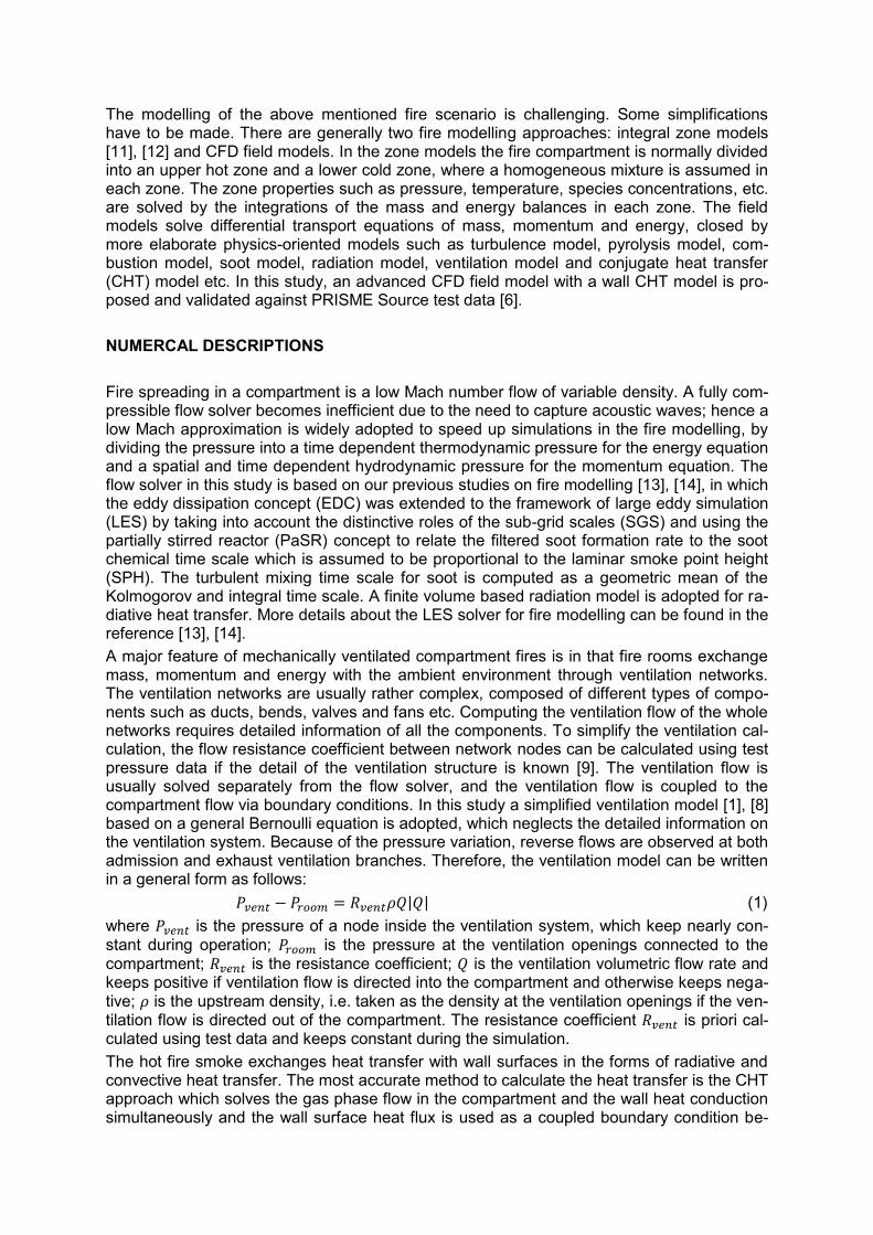
The modelling of the above mentioned fire scenario is challenging. Some simplifications have to be made. There are generally two fire modelling approaches: integral zone models [11], [12] and CFD field models. In the zone models the fire compartment is normally divided into an upper hot zone and a lower cold zone, where a homogeneous mixture is assumed in each zone. The zone properties such as pressure, temperature, species concentrations, etc. are solved by the integrations of the mass and energy balances in each zone. The field models solve differential transport equations of mass, momentum and energy, closed by more elaborate physics-oriented models such as turbulence model, pyrolysis model, com-bustion model, soot model, radiation model, ventilation model and conjugate heat transfer (CHT) model etc. In this study, an advanced CFD field model with a wall CHT model is pro-posed and validated against PRISME Source test data [6]. NUMERCAL DESCRIPTIONS Fire spreading in a compartment is a low Mach number flow of variable density. A fully com-pressible flow solver becomes inefficient due to the need to capture acoustic waves; hence a low Mach approximation is widely adopted to speed up simulations in the fire modelling, by dividing the pressure into a time dependent thermodynamic pressure for the energy equation and a spatial and time dependent hydrodynamic pressure for the momentum equation. The flow solver in this study is based on our previous studies on fire modelling [13], [14], in which the eddy dissipation concept (EDC) was extended to the framework of large eddy simulation (LES) by taking into account the distinctive roles of the sub-grid scales (SGS) and using the partially stirred reactor (PaSR) concept to relate the filtered soot formation rate to the soot chemical time scale which is assumed to be proportional to the laminar smoke point height (SPH). The turbulent mixing time scale for soot is computed as a geometric mean of the Kolmogorov and integral time scale. A finite volume based radiation model is adopted for ra-diative heat transfer. More details about the LES solver for fire modelling can be found in the reference [13], [14]. A major feature of mechanically ventilated compartment fires is in that fire rooms exchange mass, momentum and energy with the ambient environment through ventilation networks. The ventilation networks are usually rather complex, composed of different types of compo-nents such as ducts, bends, valves and fans etc. Computing the ventilation flow of the whole networks requires detailed information of all the components. To simplify the ventilation cal-culation, the flow resistance coefficient between network nodes can be calculated using test pressure data if the detail of the ventilation structure is known [9]. The ventilation flow is usually solved separately from the flow solver, and the ventilation flow is coupled to the compartment flow via boundary conditions. In this study a simplified ventilation model [1], [8] based on a general Bernoulli equation is adopted, which neglects the detailed information on the ventilation system. Because of the pressure variation, reverse flows are observed at both admission and exhaust ventilation branches. Therefore, the ventilation model can be written in a general form as follows: 𝑃𝑣𝑒𝑛𝑡 − 𝑃𝑟𝑜𝑜𝑚 = 𝑅𝑣𝑒𝑛𝑡𝜌𝑄|𝑄| (1) where 𝑃𝑣𝑒𝑛𝑡 is the pressure of a node inside the ventilation system, which keep nearly con-stant during operation; 𝑃𝑟𝑜𝑜𝑚 is the pressure at the ventilation openings connected to the compartment; 𝑅𝑣𝑒𝑛𝑡 is the resistance coefficient; 𝑄 is the ventilation volumetric flow rate and keeps positive if ventilation flow is directed into the compartment and otherwise keeps nega-tive; 𝜌 is the upstream density, i.e. taken as the density at the ventilation openings if the ven-tilation flow is directed out of the compartment. The resistance coefficient 𝑅𝑣𝑒𝑛𝑡 is priori cal-culated using test data and keeps constant during the simulation. The hot fire smoke exchanges heat transfer with wall surfaces in the forms of radiative and convective heat transfer. The most accurate method to calculate the heat transfer is the CHT approach which solves the gas phase flow in the compartment and the wall heat conduction simultaneously and the wall surface heat flux is used as a coupled boundary condition be-

tween the two phases. The modelling of the convective heat transfer in the confined com-partment is not a straightforward task. The convective heat transfer can be calculated from the empirical heat transfer coefficient which is related to the properties of gas phase, the type of convection, the orientation of solid wall. However, there lacks of well-defined large-scale fire tests for determining the coefficients in the literature. Therefore, a fixed coefficient or one-dimensional heat conduction calculations [9] were normally adopted in previous stud-ies. In this study, a three dimensional CHT model, which solves a 3D heat conduction equa-tion (2) for the solid wall, is proposed to calculate the wall heat transfer. At the wall surface a balance equation (3) of heat flux is used as a coupled thermal boundary condition between the solid and gas phases.
𝜌𝑠𝑐𝑠𝜕𝑇
𝜕𝑡= 𝑘𝑠 [
𝜕2𝑇
𝜕𝑥2+
𝜕2𝑇
𝜕𝑦2+
𝜕2𝑇
𝜕𝑧2] (2)
𝑘𝑠𝜕𝑇𝑠
𝜕𝑛|𝑤𝑎𝑙𝑙 = 𝑘𝑔
𝜕𝑇𝑔
𝜕𝑛|𝑤𝑎𝑙𝑙+𝑄𝑟 (3)
where 𝜌𝑠, 𝑐𝑠 and 𝑘𝑠 are respectively density, specific heat and heat conductivity of solid phase and assumed to constant; 𝑘𝑔 is effective heat conductivity of gas phase corrected by SGS turbulence, counteracting the under-prediction of the temperature gradient at the un-der-resolved wall boundary, 𝑄𝑟 is radiative heat flux. VALIDATION CASE AND PROBLEM DESCRIPTIONS The numerical models in the second section are validated against PRISME Source test PSR-SI-D3, which is a single room test. The test room has an internal dimension of 5 m x 6 m x 4 m ventilated by an admission branch and an exhaust branch. The ventilation branches enter the room through two 0.4 m x 0.4 m rectangular ducts. The test room con-sists of 30cm thick concrete walls and the ceiling is covered by an insulation layer of 5cm thick rock wool. A fuel pan of a surface area 0.4 m2 is situated in the room centre and hydro-genated tetra-propylene (C12H26) is used as fuel. The detailed information on the test facility and test conditions can be found in [1], [6]. The computational domain shown in Figure 1 is divided into two regions, a fluid region en-closed by a solid region (black). The fluid region is meshed using non-uniform grids with a maximum grid size of 5cm, clustering at the wall surfaces. Uniform mesh is created for the solid region, 10 grids are placed in the thickness direction. The simulation starts from zero velocity, an initial pressure of 98384 Pa and an initial temperature of 307 K for the two re-gions. No pyrolysis model is attempted for modelling the fuel burning rate in this study, in or-der to avoid its uncertainties affecting the predictions. The burning rate is defined by the ex-perimental data as shown in Figure 2, and applied as an inflow boundary condition at the fuel inlet. Reverse flows were observed at both the admission and exhaust branches in the fire test, an inlet-outlet boundary is applied at the ventilation openings where inflow/outflow velocities are calculated using the ventilation model in Section 2 according to the room pres-sure. On the all the wall boundaries of the fluid region, a no-slip velocity boundary condition and a coupled thermal boundary condition (Equation 3) are applied. A one-equation SGS turbulence model [15] is employed to represent the SGS stress and turbulent Viscosity, and two model coefficients are set to be 𝐶𝑘 = 0.05 and 𝐶𝑒 = 0.4. An etended Eddy dissipation combustion model [14] and a soot model based on smoke point concept [15] are used to model the chemical reaction rate and the formation and oxidation of soot particles, and the smoke point height of C12H26is set to 0.029 in the simulation.

Figure 1 Computational domain.
Figure 2 Fire burning rate of the test.
A finite volume method (FVM) [14] is used for radiative heat losses, in which the radiative transfer equations within multiple solid angles are solved to evaluate radiative absorption and emission. With the Gray assumption, the total absorption coefficient is decomposed into the gas absorption coefficient and the soot absorption coefficient. A total of 16 solid angles covering a hemisphere is used for the radiative transfer equations (RTE) as a compromise between computational time and accuracy. For the heat conduction of the solid region, Equation (2) is spatially discretized using a sec-ond order Gauss linear scheme and the solution is marched in time using a first order explicit scheme. The thermal properties of solid region are assumed to be constant in the simulation, and can be found in the reference [1]. The outer boundaries are assumed to thermally adia-batic. RESULTS AND DISCUSSION Figure 3 shows the comparison of the room pressure variations. The predictions follow closely with the changing trend of the experimental data. Three factors contribute to the pressure variations: combustion heat release, ventilation flows and wall heat transfer. After the ignition the combustion heat release induces a rapid pressure rise due to the increasing burning rate. The predicted variation is initially higher than the experimental data, which in-creases the exhaust flow rate and reduces the admission flow rate resulting in an early re-verse flow at the admission branch (see Figure 4). The first pressure peak, which occurs at t = 65 s corresponding to the first peak of the burning rate, is under-predicted by 700 Pa due to the over-prediction of the pressure variation which increases the energy and mass losses through the ventilation system. After the first peak, owing to the increasing heat losses via the wall heat transfer and the ventilation system, the room pressure then drops to a valley value which is well predicted by the current simulation. As the burning rate increases again after t = 160 s, the pressure variation increases and reaches to another peak because the combustion heat release outnumbers the heat losses. The extinction at t = 370 s induces the lowest valley value which is also moderately under-predicted by about 700 Pa due to the un-der-prediction of the wall heat transfer resulting from the inadequate grid resolution at the wall boundary layers.
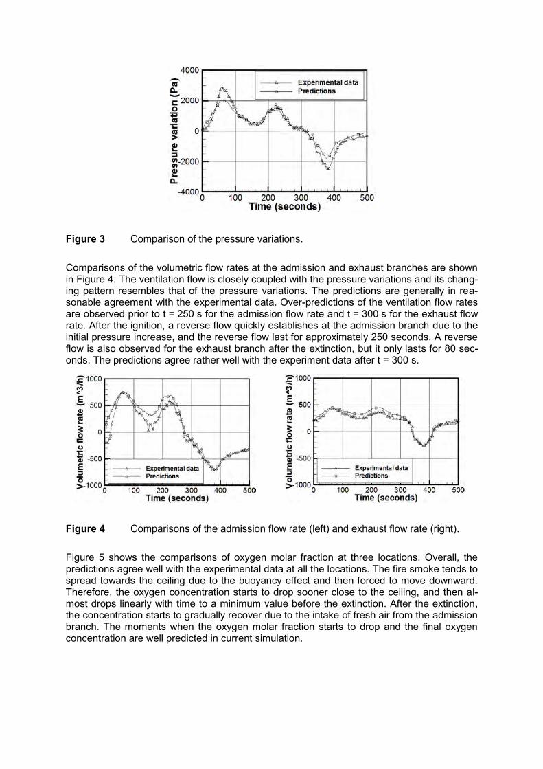
Figure 3 Comparison of the pressure variations. Comparisons of the volumetric flow rates at the admission and exhaust branches are shown in Figure 4. The ventilation flow is closely coupled with the pressure variations and its chang-ing pattern resembles that of the pressure variations. The predictions are generally in rea-sonable agreement with the experimental data. Over-predictions of the ventilation flow rates are observed prior to t = 250 s for the admission flow rate and t = 300 s for the exhaust flow rate. After the ignition, a reverse flow quickly establishes at the admission branch due to the initial pressure increase, and the reverse flow last for approximately 250 seconds. A reverse flow is also observed for the exhaust branch after the extinction, but it only lasts for 80 sec-onds. The predictions agree rather well with the experiment data after t = 300 s.
Figure 4 Comparisons of the admission flow rate (left) and exhaust flow rate (right). Figure 5 shows the comparisons of oxygen molar fraction at three locations. Overall, the predictions agree well with the experimental data at all the locations. The fire smoke tends to spread towards the ceiling due to the buoyancy effect and then forced to move downward. Therefore, the oxygen concentration starts to drop sooner close to the ceiling, and then al-most drops linearly with time to a minimum value before the extinction. After the extinction, the concentration starts to gradually recover due to the intake of fresh air from the admission branch. The moments when the oxygen molar fraction starts to drop and the final oxygen concentration are well predicted in current simulation.

(a) (b) (c)
Figure 5 Comparisons of oxygen molar fraction at three locations - (a) X = - 0.8 m,
Y = 0 m, Z = 0.35 m; (b) X = 1.5 m, Y = - 1.25 m, Z = 0.8 m; (c) X = 1.5 m, Y = - 1.25 m, Z = 3.3 m.
Figure 6 shows the comparisons of temperature at three locations. One peak value is ob-served almost at the same moment t = 300 s for each location, which is higher close to the ceiling. The peak value and its location are well predicted for all the locations. After the igni-tion the temperature is over-predicted, and after the peak moment the temperature is mod-erately under-predicted, except at the location of NE380 which is significantly over-predicted after t = 400 s due to the over-heating from the heated ceiling. The discrepancies of the temperature can be mainly attributed to the imperfectness of the ventilation model, wall CHT model and the combustion model. Among these causes, the error resulting from the CHT model due to the less resolved boundary layer is the most possible reason responsible for the discrepancies.
(a) (b) (c)
Figure 6 Comparisons of temperature at three locations - (a) X = 1.5 m, Y = - 1.25 m, Z = 1.8 m; (b) X = 1.5 m, Y = - 1.25 m, Z = 2.8 m; (c) X = 1.5 m, Y = - 1.25 m, Z = 3.8 m.
Figure 7 displays the contours of temperature in the middle plane at four different moments. After the ignition, a fire plume establishes and spreads towards the ceiling. The maximum flame temperature is observed around 1300 K. The temperature is higher inside the plume, and a hot upper layer is developed and extended towards the floor. After the extinction a temperature gradient still prevails inside the room.

Figure 7 Contours of temperature in the middle plane at t = 100 s, 200 s, 300 s, 400 s. Figure 8 displays the contours of oxygen mass fraction in the middle plane at four different moments. The fire plume consumes oxygen inside the room. As the fire plume induces pres-sure rise causing a reverse flow at the admission branch, which prevents the intake of fresh air, the depletion of oxygen results in the fire extinction.
Figure 8 Contours of oxygen mass fraction in the middle plane at t = 100 s, 200 s,
300 s, 400 s. Figure 9 displays the contours of carbon dioxide mass fraction in the middle plane at four dif-ferent moments. The maximum of carbon dioxide mass fraction is found to be 0.18 inside the fire plume. After the extinction, a nearly uniform distribution of carbon dioxide mass fraction around 10 % is observed.
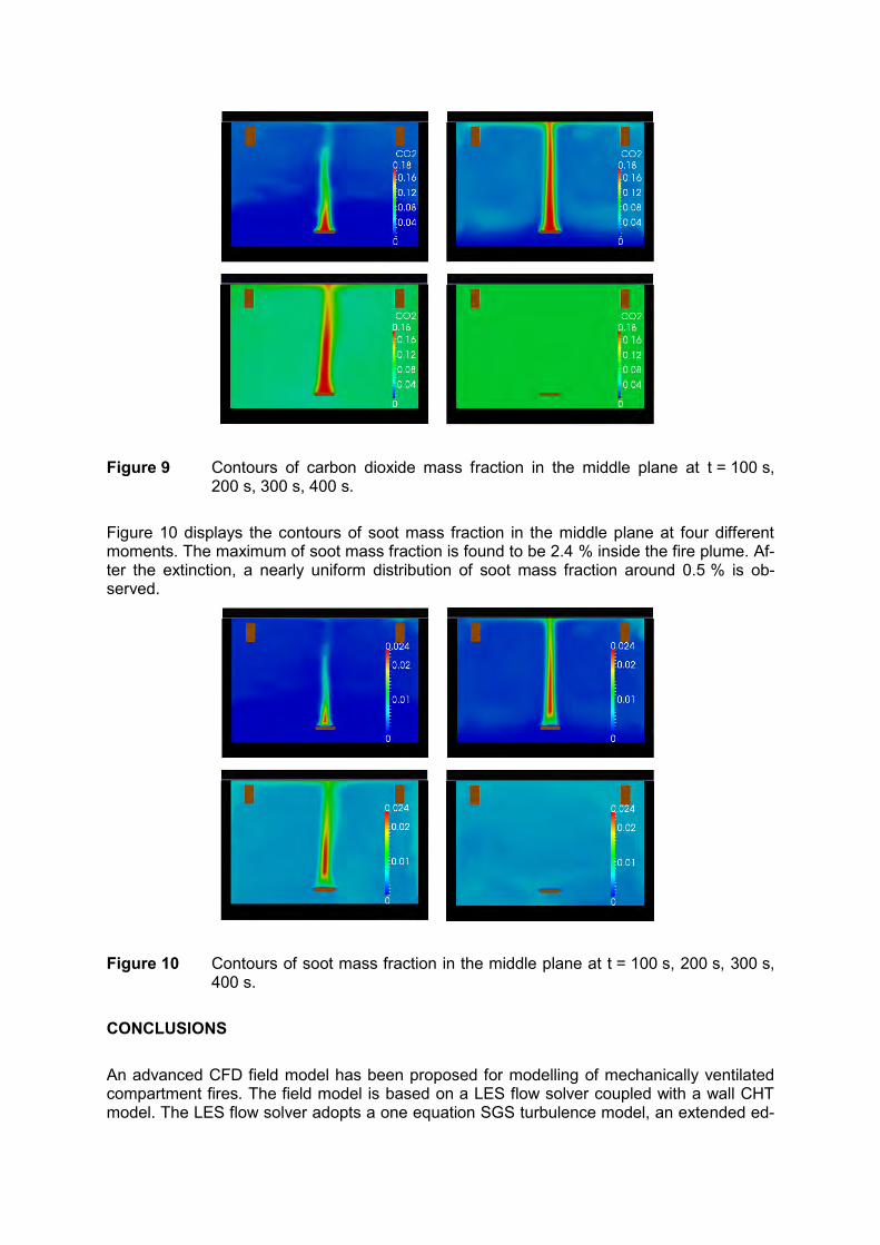
Figure 9 Contours of carbon dioxide mass fraction in the middle plane at t = 100 s,
200 s, 300 s, 400 s. Figure 10 displays the contours of soot mass fraction in the middle plane at four different moments. The maximum of soot mass fraction is found to be 2.4 % inside the fire plume. Af-ter the extinction, a nearly uniform distribution of soot mass fraction around 0.5 % is ob-served.
Figure 10 Contours of soot mass fraction in the middle plane at t = 100 s, 200 s, 300 s,
400 s. CONCLUSIONS An advanced CFD field model has been proposed for modelling of mechanically ventilated compartment fires. The field model is based on a LES flow solver coupled with a wall CHT model. The LES flow solver adopts a one equation SGS turbulence model, an extended ed-
dy dissipation combustion model, a soot model based on the concept of smoke point height, a FVM radiation model, a ventilation model based on a general Bernoulli equation. The proposed model is validated against a single room fire test, ventilated by an admission branch and an exhaust branch. The predictions of the pressure variation, the volumetric flow rates at the admission and exhaust branches, oxygen concentration and temperature are compared with experimental data. Overall, these predictions are in reasonably good agree-ment with the experimental data, closely following the experimental changing patterns. The ventilation flows and the wall heat transfer are two important features of the mechanically ventilated compartment fires, their model accuracies greatly affect the predictions and re-sponsible for the discrepancies in the current simulation. To improve the accuracies of the proposed field model, a detailed ventilation model by solving the ventilation flow in the whole ventilation system and a CHT model based on empirical correlations on the convective coef-ficient needs to be implemented, if the detailed information of ventilation networks and large-scale fire tests on the empirical correlations is available. REFERENCES [1] Bonte, F., N. Noterman, B. Merci, “Computer simulations to study interaction between
burning rates and pressure variations in confined enclosure fires”, Fire Safety Journal, Volume 62, Part B, November 2013, pp. 125-143, http://www.sciencedirect.com/science/journal/03797112/62/part/PB.
[2] Pretrel, H., W. Le Saux, L. Audouin, “Determination of the heat release rate of large scale hydrocarbon pool fires in ventilated compartments”, Fire Safety Journal, Volume 62, Part B, November 2013, pp. 192-205, http://www.sciencedirect.com/science/journal/03797112/62/part/PB.
[3] Vilfayeau, S., et al., “Numerical simulation of under-ventilated liquid-fueled compartment fires with flame extinction and thermally-driven fuel evaporation”, Proc. Combust. Inst., 35(3), 2015, pp. 2563-2571, http://perso.crans.org/epalle/M2/CA/Vilfayeau.pdf.
[4] Piece, J. B. M., J. B. Moss, “Smoke production, radiation heat transfer and fire growth in a liquid-fuelled compartment fire”, Fire Safety Journal, Volume 42(4), 2007, pp. 310-32.
[5] Hu, Z., et al., “Towards large eddy simulations of flame extinction and carbon monoxide emission in compartment fires”, Proc. Combust. Inst., 31(2), 2007, pp. 2537-2545, http://fire.nist.gov/bfrlpubs/fire07/PDF/f07032.pdf.
[6] Audouin, L., et al., OECD PRISME project: “Fires in confined and ventilated nuclear-type multi-compartments – Overview and main experimental results”, Fire Safety Jour-nal, Volume 62, Part B, November 2013, pp. 80-101, http://www.sciencedirect.com/science/journal/03797112/62/part/PB.
[7] Audouin, L., et al., “Quantifying differences between computational results and meas-urements in the case of a large-scale well-confined fire scenario”, Fire Safety Journal, 241, 2011, pp. 18-31, http://www.researchgate.net/publication/229307092_Quantifying_differences_between_computational_results_and_measurements_in_the_case_of_a_large-scale_well-confined_fire_scenario.
[8] Gay, L., B. Sapa, F. Nmira, “MAGIC and Code-Saturne developments and simulations for mechanically ventilated compartment fires”, Fire Safety Journal, Volume 62, Part B, November 2013, pp. 161-173, http://www.sciencedirect.com/science/journal/03797112/62/part/PB.
[9] Wahlqvist, J., P. van Hees, “Validation of FDS for large-scale well-confined mechanical-ly ventilated fire scenarios with emphasis on predicting ventilation system behavior”, Fire Safety Journal, Volume 62, Part B, November 2013, pp. 102-114, http://www.sciencedirect.com/science/journal/03797112/62/part/PB.
[10] Hosser, D., V. Hohm, “Application of a new model for the simulation of coupled heat transfer processes during fires to safety relevant objects in nuclear facilities”, Fire Safety
Journal, Volume 62, Part B, November 2013, pp. 144-160, http://www.sciencedirect.com/science/journal/03797112/62/part/PB.
[11] Jones, W: P., et al., CFAST: Consolidated Model of Fire Growth and Smoke Transport (Version 6), Technical Reference Guide, NIST SP 1026; NIST Special Publication 1026; Version 6; National Institute of Standards and Technology (NIST), Gaithersburg, MD, USA, Revision April 2009, http://fire.nist.gov/bfrlpubs/fire09/art026.html.
[12] United States Nuclear Regulatory Commission (U.S. NRC), Office of Nuclear Regulato-ry Research (RES), and Electric Power Research Institute (EPRI), Verification and Vali-dation of Selected Fire Models for Nuclear Power Plant Applications, Volume 6: MAGIC, Final Report, NUREG-1824 and EPRI 1011999, Washington, DC, and Palo Alto, CA, USA, May 2007, http://pbadupws.nrc.gov/docs/ML0717/ML071730504.pdf.
[13] Chen, Z., et al., “Large eddy simulation of a medium-scale methanol pool fire using the extended eddy dissipation concept”, Int. J. Heat Mass Tran., 70, 2014, 389-408, http://www.sciencedirect.com/science/article/pii/S0017931013009642.
[14] Chen, Z., et al., “Extension of the eddy dissipation concept and smoke point soot model to the LES frame for fire simulations”, Fire Safety Journal, Volume 64, February 2014, pp. 12-26, http://www.sciencedirect.com/science/article/pii/S0379711214000125.
[15] Menon, S., P. K. Yeung, W.W. Kim, “Effect of subgrid models on the computed inter-scale energy transfer in isotropic turbulence”, Computational Fluids 25 (2), 1996, pp. 165–180.
23rdInternational Conference on Structural Mechanics in Reactor Technology (SMiRT 23) - 14h
International Post-Conference Seminar on “FIRE SAFETY IN NUCLEAR POWER PLANTS AND INSTALLATIONS“
GLOBAL SENSITIVITY ANALYSIS USING EMULATORS, WITH AN EXAMPLE ANALYSIS OF LARGE FIRE PLUMES
BASED ON FDS SIMULATIONS
Adrian Kelsey
Health and Safety Laboratory, Harpur Hill, Buxton, United Kingdom ABSTRACT Uncertainty in model predictions of the behaviour of fires is an important issue in fire safety analysis in nuclear power plants. A global sensitivity analysis can help identify the input pa-rameters or sub-models that have the most significant effect on model predictions. However, to perform a global sensitivity analysis using Monte Carlo sampling might require thousands of simulations to be performed and therefore would not be practical for an analysis based on a complex fire code using computational fluid dynamics (CFD). An alternative approach is to perform a global sensitivity analysis using an emulator. Gaussian process emulators can be built using a limited number of simulations and once built a global sensitivity analysis can be performed on an emulator, rather than using simulations directly. Typically reliable emulators can be built using ten simulations for each parameter under consideration, therefore allowing a global sensitivity analysis to be performed, even for a complex computer code. In this paper we use an example of a large scale pool fire to demonstrate an emulator based approach to global sensitivity analysis. In that work an emulator based global sensitivity analysis was used to identify the key uncertain model inputs affecting the entrainment rates and flame heights in large Liquefied Natural Gas (LNG) fire plumes. The pool fire simulations were performed using the Fire Dynamics Simulator (FDS) software. Five model inputs were varied: the fire diameter, burn rate, radiative fraction, computational grid cell size and choice of turbulence model. The ranges used for these parameters in the analysis were determined from experiment and literature. The Gaussian process emulators used in the analysis were created using 127 FDS simulations. The emulators were checked for reliability, and then used to perform a global sensitivity analysis and uncertainty analysis. Large-scale ignited releases of LNG on water were performed by Sandia National Laborato-ry (SNL) in 2009. At the largest LNG release rate the flames did not cover the entire area of the LNG spill, this behaviour had not been observed in previous large-scale experiments. Al-so the height of the flames was also greater than expected from previous large-scale tests. One possible explanation for the observed behaviour is that in this very large-scale release the speed at which air and fuel vapour was drawn into the fire exceeded the flame speed. Therefore the flames could not propagate upwind to ignite the whole surface of the LNG pool. Fuel vapour from the unignited region, drawn into the fire, may also account for the higher flame height. A global sensitivity analysis allows the influence of uncertain parameters on the quantities of interest to be examined. This publication and the work it describes were funded by the Health and Safety Executive (HSE). Its contents, including any opinions and/or conclusions expressed, are those of the authors alone and do not necessarily reflect HSE policy. © Crown Copyright 2015
INTRODUCTION Developing and using models, sensitivity analyses are used to identify influential parame-ters. Once influential parameters have been identified care can be taken in finding or collect-ing data, to set the parameter value used in the model, or to ensure that a suitable represen-tation is used in the model. A local sensitivity analysis, varying parameter values about a base-line can often identify significant parameters for this purpose. In consequence modelling for safety analysis, for example, fire safety analysis, there is fre-quently interest across a range of possible operational conditions and there will often be un-certainty about the values of parameter that should be used. Rather than a local sensitivity analysis, considering the sensitivity at a single set of conditions, there is interest in the re-sponse over the full, global, range of conditions. In this situation a global sensitivity analysis can be used to identify the parameters that are important over the full range of operating conditions [1]. “Design of Experiments” [2] was developed to identify influential parameters in experiments. It has been applied to the sensitivity analysis of simulations from fire models [3] and shown to be able to produce useful information about the sensitivity of output quantities of interest using a small number of simulations using a fractional factorial design. However, deterministic computer models, such as fire models, do not have the same behav-iour as experiments. In particular repeating a simulation should result in the same result. One result is that if a parameter has no effect on an output of interest simulations that only vary in that parameter do not provide additional information. This has led to the extension of the “Design of Experiments” to the “Design and Analysis of Computer Experiments” [4]. Performing global sensitivity analyses directly, using a Monte Carlo approach is not possible unless the duration of model runs is very short. A Monte Carlo analysis may require thou-sands of model evaluations and the computing resource and time soon becomes prohibitive. One approach to this problem is the use of efficient designs, for example, extended-FAST (Fourier amplitude sensitivity test) [5] is a computationally efficient method to calculate main and total effect sensitivity indices. An alternative is the use of statistical emulators. In this approach a relatively small number of simulations are used to build an emulator. Once built an emulator can be used as a cheap way of making predictions at conditions for which simu-lations have not been performed. It can also be used as the basis for sensitivity and uncer-tainty analysis, calibration and optimisation. The emulator approach is more flexible in the in-formation that can be obtained than extended-FAST or a factorial design for experiments. Building an emulator may require more simulations to be performed than a fractional factorial design. Loeppky et al [6] investigate and agree with a rule of thumb suggesting that a relia-ble emulator needs ten simulations per parameter. However, the resulting emulator can be used as a cheap predictor of the original model, in uncertainty and sensitivity analysis, cali-bration, and optimisation. In this paper we describe performing an emulator based global sensitivity analysis using an example of large scale LNG fire plumes using FDS simulations, based on work described in Kelsey et al. [7]. GLOBAL SENSITIVITY USING AN EMULATOR The approach to global sensitivity analysis described here is based on Bayesian Analysis of Computer Code Output (BACCO). O’Hagan [8] reviews this approach in an article providing a tutorial introduction. A software tool to perform global sensitivity analysis using the BACCO approach, GEM (Gaussian Emulation Machine), was developed by the research group of O’Hagan; the sensitivity analysis is described in Oakley and O’Hagan [9]. The GEM software uses a graphical interface to setup and perform the sensitivity analysis and is freely available for non-commercial use [10]. The interface can be used to create a design of simulations to
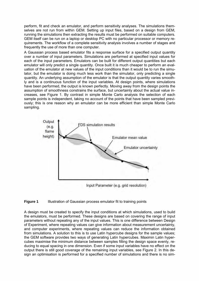
perform, fit and check an emulator, and perform sensitivity analyses. The simulations them-selves are not run from within GEM. Setting up input files, based on a design from GEM, running the simulations then extracting the results must be performed on suitable computers. GEM itself can be run on a laptop or desktop PC with no particular processor or memory re-quirements. The workflow of a complete sensitivity analysis involves a number of stages and frequently the use of more than one computer. A Gaussian process based emulator fits a response surface for a specified output quantity over a number of input parameters. Simulations are performed at specified input values for each of the input parameters. Emulators can be built for different output quantities but each emulator will only predict a single quantity. Once built it is much cheaper to perform an eval-uation of the emulator at new values of the input conditions than it would be to run the simu-lator, but the emulator is doing much less work than the simulator, only predicting a single quantity. An underlying assumption of the emulator is that the output quantity varies smooth-ly and is a continuous function of the input variables. At design points, where simulations have been performed, the output is known perfectly. Moving away from the design points the assumption of smoothness constrains the surface, but uncertainty about the actual value in-creases, see Figure 1. By contrast in simple Monte Carlo analysis the selection of each sample points is independent, taking no account of the points that have been sampled previ-ously; this is one reason why an emulator can be more efficient than simple Monte Carlo sampling.
Figure 1 Illustration of Gaussian process emulator fit to training points A design must be created to specify the input conditions at which simulations, used to build the emulators, must be performed. These designs are based on covering the range of input parameters without repeating any of the input values. This is one difference between Design of Experiment, where repeating values can give information about measurement uncertainty, and computer experiments, where repeating values can reduce the information obtained from simulations. A solution to this is to use Latin hypercube designs for the sample values; the GEM software provides two ways of generating Latin hypercubes. Maximin Latin hyper-cubes maximise the minimum distance between samples filling the design space evenly, re-ducing to equal spacing in one dimension. Even if some input variables have no effect on the output there is still good coverage of the remaining input variables, see Figure 2. In this de-sign an optimisation is performed for a specified number of simulations and there is no sim-

ple way to increase the number of simulations in a design. Alternatively an LP-tau design can be used; this is a pseudorandom number sequence [11]. The LP-tau design is faster to generate and the design can be extended, filling in gaps in the existing design, but it does not fill the space as evenly as the maximin Latin hypercube. In models of physical systems it is often found that only a few parameters are active. This is why Latin hypercube designs, that do not repeat values, are useful, as when one dimension is removed from the design the input conditions of the simulations remain distinct.
Figure 2 Maximin Latin hypercube design, reducing from three to one dimension Once an emulator has been built the performance should be checked. The approach used in GEM is to perform a ‘leave-one-out’ cross-validation. Since the surface of a Gaussian pro-cess emulator passes through the predicted output values from all the simulations compari-son of simulation and emulator cannot be used as a direct check on the fit of the emulator. Instead emulators are fitted leaving out the prediction from one simulation at a time, a ‘leave-one-out’ cross-validation, giving the same number of emulators as simulations performed. Each emulator is then used to predict the simulation that it does not include and the fit is checked. Once an emulator has been fitted and checked the sensitivity analysis can be performed. GEM can perform two types of sensitivity analysis, variance based and mean based. The variance based analysis predicts main and total effects, the quantities predicted by an ex-tended-FAST analysis [5]. The main effect of a parameter is the amount of the variance ex-plained by that parameter alone; the total effect of a parameter is the sum of its main effect and all the possible interactions including that parameter. If the total effect of a parameter is equal to the main effect then no interactions involving that parameter contribute to the vari-ance. If they differ then interactions involving that parameter do contribute to the variance. The sensitivity analysis can then be repeated including specified interactions to examine their effect. A variance based analysis can identify important parameters and interactions, but does not, by itself, explain how the parameters contribute to the variance. The other sen-sitivity analysis that can be performed using GEM is mean based. The mean value of pa-rameters can be plotted across their range to examine how they change and hence how that parameter contributes to the variance. APPLICATION OF SENSITIVITY ANALYSIS TO LARGE LNG FIRE PLUMES An emulator based global sensitivity analysis was performed to investigate behaviour ob-served during the Phoenix tests performed by Sandia National Laboratory in the United States. These tests involved the largest LNG releases ever made; the LNG was released on-to a large pool of water and ignited [12]. In the largest of the Phoenix tests only part of the LNG pool was covered by flames and the flame height was greater than expected. This be-
haviour is analysed by Betteridge et al [13] and a global sensitivity analysis is described in Kelsey et al. [7]. The outputs of interest in the sensitivity analysis were the plume flame height and the entrainment velocity into the base of the fire plume, as the velocity may have been high enough to limit flame spread and unignited vapour drawn into the fire plume may account for the greater than expected flame height being. The fire plume simulations were performed using FDS version 6 [14], which is a freely avail-able CFD code developed by the National Institute of Standards and Technology (NIST) in the United States. The model inputs used in the global sensitivity analysis are described in Table 1. Table 1 Global sensitivity analysis inputs and their ranges
Model Input Parameter Range
Pool fire diameter 10 – 100 m
Burn rate 0.05 – 0.5 kg m-2 s-1
Radiative fraction 0.20 – 0.35
Grid resolution (D∗/∆x) 16 – 40
Turbulence model Deardoff or Smagorinsky
The range of pool fire diameters considered covers both the smaller, 21 m, and larger, 83 m, LNG spill diameters in the Phoenix tests. In the former flames spread over the whole surface of the spill, in the latter the flames were limited to a region approximately 56 m in diameter. The range of burn rates examined is large, this allows for the possibility, considered in Bet-teridge et al. [13], that vapour from the whole of the LNG spill contributed to the burn rate in the smaller region where burning occurred. The other three parameters considered are re-lated to the setup of the model. The radiative fraction is a pragmatic approach to the problem that the mesh is not sufficiently fine to resolve flame fronts and therefore maximum tempera-tures will be under-predicted. The lower end of the range corresponds to a clear flame, the higher a smoky hydrocarbon fire, the default in FDS. The range of grid resolution studied run from the top end of the range used for the Heskestad flame height in the FDS validation manual [15] to a value suggested by Chung and Devaud [16] as a good compromise be-tween computing time and accuracy. All of these parameters are continuous; the final pa-rameter though is not continuous, rather it is a “switch” between two different turbulence models. Smagorinsky [17] and Deardorff [18] are the default turbulence models in FDS ver-sions 5 and 6 respectively. A 127 member LP-tau sequence was used for the design of simulation input conditions. Challenor [19] examined this type of design for looking at the influence of a switch in a global sensitivity analysis. The 127 member design is a Latin hypercube design with 2� − 1 mem-bers, where = 7. The first 2� � − 1 members and the remaining 2� � members are also each Latin hypercube designs. If one turbulence model is used for the members of the first Latin hypercube design, with 63 members, and the other turbulence model for the remaining 64 members of the 127 member design, then separate emulators can be fitted for the two turbulence models. This avoids potential problems with the smoothness and continuity as-sumptions underlying a Gaussian process emulator. The choice of a 127 member design al-lows a design containing two Latin hypercube designs and follows the rule of thumb of 10 simulations per parameter.

RESULTS The results of a leave-one-out cross-validation are shown in Figure 3, indicating that the em-ulators are suitable for use in a sensitivity analysis.
a) flame height (m) b) entrainment velocity (m s-1)
Figure 3 Cross-validation of emulators for the Smagorinsky turbulence model The variance based global sensitivity analysis showed that fire diameter has the greatest ef-fect on both flame height and entrainment velocity, accounted for over 75 % of the total vari-ance. The burn rate accounted for almost all the remaining variance for the flame height, with a small amount of interaction between fire diameter and burn rate. The remaining parameters contributed very little to the variance in the flame height. Plotting mean emulator predictions of flame height, Figure 4, shows the influence of fire di-ameter and burn rate. The values of the grid resolution and radiative fraction are set at the middle of their ranges, as the variance based analysis showed these had little effect on the flame height. Emulator predictions for both turbulence models are plotted showing that they also have little effect on flame height, as indicated by the variance based analysis.
Figure 4 Emulator predictions of flame height against fire diameter, showing influence
of fire diameter and burn rate

The variance in the entrainment velocity is dominated by the fire diameter but burn rate, grid resolution and the turbulence model also contribute to the variance. The effect of grid resolu-tion is greater with the Deardorff than the Smagorinsky turbulence model. Plotting mean emulator predictions of radial velocity, cf. Figure 5, shows the influence of fire diameter and burn rate, but also the effect of grid resolution and turbulence model. Predic-tions are shown for values of grid resolution close to the ends of the range used in the sensi-tivity analysis. These show that the predictions using both turbulence models converge at the higher grid resolution. The predictions made using the Deardorff turbulence model are more affected by grid resolution than those using the Smagorinsky turbulence model. This explains the greater contribution to the variance for the Deardorff turbulence model. Vari-ance based sensitivity analysis shows that both flame height and entrainment velocity are most sensitive to the fire diameter and burn rate. The other parameters considered have much less influence. Though care must be taken to ensure adequate mesh resolution when predicting the entrainment velocity, the flame height shows less sensitivity to the mesh used.
A variance based sensitivity analysis by itself shows which parameters affect the flame height and entrainment velocity, but does not explain how they affect them. Plotting the mean response of the parameters shows how they respond to the sensitive parameters. The predicted flame height is sensitive to burn rate, and increases with increasing burn rate. An increased burn rate, due to vapour from non-burning regions of the LNG pool, could there-fore increase flame height. The predicted entrainment velocity is sensitive to both fire diame-ter and burn rate. Betteridge et al. [13] note that Gottuk and White [20] report flame spread velocities of 2 m s-1 for liquid pool fires. The predicted entrainment velocities are higher than this value so tend to support the hypothesis that entrainment velocities could inhibit fire spread causing non-burning regions. However, further work would be required to quantify burning velocities in LNG pool fires to be sure that this was an explanation of the observed behaviour.
Figure 5 Emulator predictions of entrainment velocity against fire diameter, showing in-
fluence of fire diameter, burn rate, grid resolution and turbulence model

CONCLUSIONS The combination of variance based and mean based sensitivity analysis, which is possible using emulator based sensitivity analysis, can be used to identify sensitive parameters and how they affect the quantities of interest. The analysis of fire plume behaviour shows that the fire diameter is the most influential parameter and that for large diameter fires the entrain-ment velocity into the plume could be sufficient to limit upwind flame spread, stopping the burning area from covering the whole of a large LNG pool. Predictions of quantities of interest show different sensitivities to parameters. In the fire plumes studied both flame height and entrainment velocity are most sensitive to fire diame-ter followed by burn rate. However, the entrainment velocity also shows sensitivity to the tur-bulence model and grid resolution. During the international OECD PRISME Project, mechanically ventilated multi-compartment fires were studied experimentally. These tests are complex; to capture the observed behav-iour the interaction between mechanical ventilation and fire in the compartments must be modelled. To simulate these experiments with CFD a network ventilation model must be coupled with the CFD code, therefore increasing the number of physical and model parame-ters needed. Sensitivity analysis can be used to to identify important parameters and under-stand the effect that inputs have on output quantities. By identifying where effort should be concentrated the sensitivity analysis can help to inform the design of validation studies. Sen-sitivity analysis can also be used in the evaluation of consequence models and their uncer-tainties, complementing scientific assessment, verification and validation. Emulators allows global sensitivity analyses to be used with CFD models, where otherwise the number of sim-ulations needed could not be performed, and therefore can contribute to the use of CFD in nuclear fire safety. ACKNOWLEDGEMENTS The author would like to acknowledge contributions by Steven Betteridge, Shell, Simon Gant and Kevin McNally, Health and Safety Laboratory to the work described in this paper. REFERENCES [1] Saltelli, A., K. Chan, and E. M. Scott, Sensitivity analysis, John Wiley & Sons Ltd, 2003. [2] National Insitute of Standards and Technology (NIST), NIST/SEMATECH e-Handbook
of Statistical Methods, NIST/SEMATECH, Gaithersburg, MD, USA, 2013, http://www.itl.nist.gov/div898/handbook/, accessed 12th August 2015.
[3] Suard, S., S. Hostikka, and J. Baccou, “Sensitivity analysis of fire models using a frac-tional factorial design,” Fire Safety Journal, Vol. 62, 2013, pp. 115-124, http://www.sciencedirect.com/science/article/pii/S0379711213000362.
[4] Sacks, J., et al.., “Design and analysis of computer experiments,” Statistical Science Vol. 4, 1989, pp. 409-435, http://www.stat.osu.edu/~comp_exp/jour.club/Sacks89.pdf.
[5] Saltelli, A., S. Tarantola, and K. P.-S. Chan, “A Quantitative Model-Independent Method for Global Sensitivity Analysis of Model Output,” Technometrics Vol. 41, 1999, pp. 39-56, http://www.researchgate.net/publication/243587760_A_Quantitative_Model-Independent_Method_for_Global_Sensitivity_Analysis_of_Model_Output.
[6] Loeppky, J. L., S. Sacks, and W. J. Welch, “Choosing the Sample Size of a Computer Experiment: A Practical Guide,” Technometrics, Vol. 51, 2009, pp. 366-376, http://www.stat.osu.edu/~comp_exp/jour.club/LoeppkySacksWelch_TNX2009.pdf.
[7] Kelsey, A., et al., “Application of global sensitivity analysis to FDS simulations of large LNG fire plumes,” IChemE Hazards 24, Edinburgh, United Kingdom, May 2014. Availa-ble from http://www.icheme.org/events/conferences/past-conferences/2014/hazards-24/open%20access%20papers.aspx, accessed 12th August 2015.
[8] O’Hagan, A., “Bayesian analysis of computer code outputs: a tutorial,” Reliability Engi-neering and System Safety, Vol. 91, 2006, pp. 1290-1300, http://www.researchgate.net/publication/222548735_Bayesian_analysis_of_computer_code_outputs_A_tutorial.
[9] Oakley, J. E. and A. O’Hagan, “Probabilistic sensitivity analysis of complex models”, Journal of the Royal Statistical Society, Vol. B 66, 2004, pp. 751-769, http://citeseerx.ist.psu.edu/viewdoc/download?doi=10.1.1.470.6932&rep=rep1&type=pdf.
[10] Kennedy, M. C., GEM-SA, version 1.1 software: Gaussian Emulation Machine for Sen-sitivity Analysis, 2005, http://www.tonyohagan.co.uk/academic/GEM/index.html, ac-cessed 10th August 2015.
[11] Sobol, I. M., et al., Quasirandom sequence generators, IPM ZAK No. 30, Keldysh Inisti-tute of Applied Mathematics, Russian Academy of Sciences, Moscow, Russia,1992.
[12] Blanchat, T., et al., The Phoenix Series Large scale LNG Pool Fire Experiments, SAND2010-8676, Sandia National Laboratories (SNL), Albuquerque, NM, USA, 2011, http://prod.sandia.gov/techlib/access-control.cgi/2010/108676.pdf.
[13] Betteridge, S., at al., “Consequence modelling of large LNG pool fires on water”, IChemE Hazards 24, Edinburgh, United Kingdom, May 2014, http://s177835660.websitehome.co.uk/research/betteridge_hoyes_gant_ivings_2014_hazards24_preprint.pdf.
[14] McGrattan, K., et al., Fire Dynamics Simulator, Technical Reference Guide, Sixth Edi-tion, NIST Special Publication 1018, Vol. 1: Mathematical Model,National Institute of Standards and Technology (NIST), Gaithersburg, MD, USA, and VTT Technical Re-search Centre of Finland, Espoo, Finland, November 2013, http://firemodels.github.io/fds-smv/.
[15] McGrattan, K., et al., Fire Dynamics Simulator, Technical Reference Guide, Sixth Edi-tion, NIST Special Publication 1018, Vol. 3: Validation Guide, National Institute of Standards and Technology (NIST), Gaithersburg, MD, USA, and VTT Technical Re-search Centre of Finland, Espoo, Finland, November 2013, http://firemodels.github.io/fds-smv/.
[16] Chung, W., and C. B. Devaud, “Buoyancy-corrected k-ε models and large eddy simula-tion applied to a large axisymmetric helium plume”, International Journal of Numerical Methods in Fluids, Vol. 58, 2008, pp. 57-89, http://onlinelibrary.wiley.com/doi/10.1002/fld.1720/abstract, assessed 14th August 2015.
[17] Smagorinsky, J., “General circulation experiments with the primitive equations. I. The basic experiment”, Monthly Weather Review, Vol. 91, 1963, pp. 99-164, http://docs.lib.noaa.gov/rescue/mwr/091/mwr-091-03-0099.pdf.
[18] Deardorff, J. W., “Numerical investigation of neutral and unstable planetary boundary layers”, Journal of Atmospheric Sciences, Vol. 29, 1972, pp. 91-115, http://journals.ametsoc.org/doi/pdf/10.1175/1520-0469(1972)029%3C0091%3ANIONAU%3E2.0.CO%3B2.
[19] Challenor, P., “Designing a computer experiment that involves switches”, Journal of Sta-tistical Theory and Practice, Vol. 5, 2011, pp. 47-57, http://www.stat.osu.edu/~comp_exp/jour.club/chaloner-2011.pdf.
[20] Gottuk, D. T. and D. A. White, “Liquid Fuel Fires”, Chapter 15, Section 2, SFPE Hand-book of Fire Protection Engineering, Third Edition, National Fire Protection Association, Inc., Quincy, MA, USA, 2002.

23st International Conference on Structural Mechanics in Reactor Technology (SMiRT 23) - 14th
International Post-Conference Seminar on “FIRE SAFETY IN NUCLEAR POWER PLANTS AND INSTALLATIONS“
SENSITIVITY ANALYSIS OF FDS 6 RESULTS FOR NUCLEAR POWER PLANTS
Daniel Alvea r1, Eduardo Puente 1, Orlando Abreu 1 and Julián Peco 2
1 Group GIDAI – Fire Safety-Research and Technology, University of Cantabria,
Santander, Spain
2 Consejo de Seguridad Nuclear, Madrid, Spain
ABSTRACT The Spanish standard “Instruction IS-30, Rev. 1” (February 21, 2013) allows the new ap-proaches of risk informed performance based design (PBD) The Spanish standard “Instruc-tion IS-30, rev. 1” (February 21, 2013) for demonstrating the safe shutdown capability in case of fire in nuclear power plants. In this sense, fire computer models have become an in-teresting tool to study real fire scenarios. Such models use a set of input parameters that de-fine the features of the physical domain, material, radiation, turbulence, etc. This paper analyses the impact of the grid size and different sub-models of the fire simula-tion code FDS, version 6 with the objective to evaluate and define their relative weight in the final simulation results. For the grid size analysis, two different scale scenarios were select-ed, the bench scale test PENLIGHT and a large-scale test similar to Appendix B of NUREG -1934 (17 m x 10 m x 4.6 m, with an ignition source of 2 MW and 16 cable trays). For the sub-model analysis, the PRS-INT4 real scale configuration of the INTEGRAL experimental campaign of the international OECD PRISME Project has been used. The results offer relevant data for users and show the critical parameters that must be se-lected properly to guarantee the quality of the simulations. INTRODUCTION The work is based upon computational modelling of fires during the last decade. In the fire community, the use of computational fluid dynamics (CFD) has become usual and among all the codes developed, it is mandatory to highlight the LES (Large Eddy Simulation) code Fire Dynamics Simulator (FDS) [1]. It has been released the sixth version of the code and it fights against important challenges since it is widely used for many fire scenarios. The range of spatial scales covered goes from millimetres to hundreds of meters. When using the FDS code, a first question arises on the selection of a suitable mesh size: it must be little enough to resolve turbulence-related questions, but it must be also large enough to ensure a realistic time scale. For that purpose some stability of the solution (i.e. temperature, velocity) is needed to be ensured. The selection of a mesh is the first step to get a numerical solution and has been widely treated in many documents; however in the field of modelling for nuclear power plants the main reference is the NUREG-1824 [2]. Another consideration to highlight is the dependence between input and output values when a criterion is fixed. From the results of this relation, the parameters that need a more precise evaluation to input the code are identified, and complementary, which parameters do not need such precision. In this sense, it is worth to highlight the work done by Hostikka [3]. He
205
has created a model that combines Monte Carlo analysis and Computational Fluid Dynamics (CFD) modelling. Najm [4] used probabilistic uncertainty that propagates from input to output in a number of different CFD codes when the input has been characterized probabilistically. Recently, in the frame of the international PRISME (Propagation d’un incendie pour des scénarios multi-locaux élémentaires, French acronym for “Fire Propagation in Elementary Multi-Room Scenarios”) Project launched by the OECD (Organisation for Economic Co-operation and Development) Nuclear Energy Agency (NEA), Suard et al. [5] have applied a factorial design to study sensitivity of the fifth version of the FDS code. However, NUREG-1824 [2] evaluated the results of the fourth version of the code, which had a different finite difference term to resolve the flow model and therefore, we deal with the evaluation of the sixth version of FDS for different values of the cell size, which is very im-portant to use the code properly. GRID SENSITIVITY In this study, different values of the cell size have been tested using different types of heat sources. The temperature was used as the criterion to get a value that quantifies the differ-ence between both base and test cases. Following [2] or the User´s Guide of FDS, Section 6.3.6, we have a first approach to evaluate the mesh size. In this approach, the characteristic cell size, Dz, is related to the characteris-tic diameter of fire, D*. In these documents, values of the ratio D*/Dz between 4 and 16 were tested and recommended.
�∗ = � ����√�
� �� (1)
where �� is the heat release rate [J/s], �, �� and T are respectively the density [kg/m3], specif-ic heat [J/kg.K] and temperature of ambient air, and g [m/s2] is the acceleration of gravity field.
���������� = �∑ � !" ���#$%"!����& �'#(� (2)
) = *+,� !" � !" ------- (3)
Where �.�/� is the temperature of the case i at time t, and N the number of values of temper-ature for each case performed. ) is the squared relative error and �����------ is the average tem-perature. Penlig ht Scenario The airdrop configuration of the Penlight tests [6] was used as scenario to test grid sensitivity because it is a single geometry composed by a cylindrical oven and a cable in the symmet-rical axe of the cylinder. In this configuration, only radiation has influence on heating the sur-face of the cable. Nonetheless, we are interested in testing two configurations of the cable: on the one hand, an inert cable inputted by using both the PART and the OBST instructions of the code. On the other hand, the same scenario was tested with a reactive cable and py-rolysis effects were included. The cylindrical oven has length of 0.8 m and a diameter of 0.51 m. Cable temperature was evaluated 2 mm deeper into the cable as stated in the validation tests performed by the de-velopers of FDS during the PRISME Project [7]. For the grid analysis, the same temperature program as the LOWER case studied in the validation examples was used. Air temperature did not show any change of the cell sizes tested and therefore it was not further discussed. The computational domain was a cube of 0.6 m x 0.45 m x 0.45 m.
206
For the non-reactive cable, a plastic material is used, with a density of 1959 kg/m3, a con-ductivity of 0.2 W/m.K and a specific heat, and 1500 J/kg.K, respectively. Table 1 and Table 2 provide a summary of cases studied and the results obtained. Table 1 Tests cases with non-reactive cable
Case No. of cells Size (shape) Code
1 970 5 cm (cubic) PART
2 150 10,9,9 cm (parallelepiped) PART
3 7760 2.5 cm (cubic) PART
4 970 5 cm (cubic) OBST
5 150 10,9,9 cm (parallelepiped) OBST
The results were compared for each criterion to a different base case. Thus, the first column of the results shows the relative squared error regarding the base case with a cell size of 0.025 m. The second column points out the differences between PART and OBST cable characterizations. The results were compared against two base cases of cell sizes 0.05 m and 0.1 m. Table 2 Results of non-reactive cable cases
Case 0 Squared 0 OBSTvsPART
1 3.97 % BASE
2 5.67 % BASE
3 BASE -
4 4.25 % 0.57 %
5 6.38 % 0.99 %
Figure 1 shows the temperatures obtained at 2 mm depth inside the cable from numerical treatment. In green colour, we can see the PART results, while black colour characterizes the OBST results. From the results obtained, it can be observed that there are no differences between OBST and PART descriptions at the same cell size (below 1 %). However, for different grid sizes, the squared relative differences are in the order of 4 %, if the mesh size is multiplied by 2, and around 6 %, if it is multiplied by 4. It can be observed that some properties of the curves are quite different, for example the temperature peak reached by the cable from coarse cells (0.1 m) is at least 30 ºC higher than those obtained from cell sizes of 0.05 and 0.025 m.
207

Figure 1 Cable temperature during numerical simulation For reactive cables, a different definition of the main components of the cable were used, PVC. The definition of the PVC components was made by the parameters provided in Table 3. Table 3 Properties of reactive cable components
Property Value
Density 1200 kg/m3
Specific heat 1370 J/kg.K
Conductivity 0.12 W/m.K
Emissivity 0.21
N_Reactions 1
Nu_Spec 1
Spec_Id PVC_surrogate
Reference Temperature 257 ºC
Heat_of_Reaction 1500 J/kg
The PVC_surrogate had a heat of combustion of 16400 J/kg.
208

Table 4 Tests cases with reactive cables
Case No. of cells Size (shape) Code
1 7760 2.5 cm (cubic) PART
2 970 5 cm (cubic) PART
3 150 10,9,9 cm (parallelepiped) PART
4 150 10,9,9 cm (parallelepiped) OBST
5 970 5 cm (cubic) OBST
6 7760 2.5 cm (cubic) OBST
Table 5 demonstrates that the error, when comparing characterizations (PART vs. OBST), has a different behaviour regarding to the no reactive cable. It seems that there are some differences between both if the size of the cell decreased enough (3 % at cell size of 0.025 m). It is likely because the PART characterization was created in the development of THIEF [8] model and for that model, the cable must be non-reactive. However, for squared relative error, there is the same trend as for the non-reactive case. Higher cell size corre-sponds to higher squared error but it shows a difference with regard to reactive cables, the mesh with a cell size of 0.05 m seems to be more accurate. Table 5 Results of reactive cable cases
Case 0 Squared 0 OBSTvsPART
1 BASE BASE
2 5.39 % BASE
3 12.33 % BASE
4 12.76 % 0.28 %
5 2.27 % 0.24 %
6 BASE 3.18 %
Figure 2 demonstrates that the shape of the temperature curve inside the cable was similar for the cases of cell size 0.05 m and 0.025 m; however, the coarse mesh (cell size 0.1 m) predicts a maximum temperature higher than the finest meshes and shows a thermal in-crease faster than these ones.
209

Figure 2 Cable temperature during numerical simulation Switchgear Room Scenario The sensitivity analysis in a scenario accounting for fire sources which Equation 1 can de-scribe completes the study of the grid influence to the results. In that sense, a simulation of a typical nuclear power plant room was perfomed, a switchgear room [8] with electrical cabi-nets and cable trays. In this scenario, neither non-reactive cables nor the PART characteri-zation were considered. The room has a size of 17 m length x 10 m width x 4.6 m height. Inside the room, 16 cable trays, 12 electrical cabinets, an exhaust duct, 3 vents and a fire source of 2 MW are in-stalled. The analysis includes environment temperature and cable temperatures 2 mm in depth of the cable for two locations in the room. Figure 3 shows these locations highlighted with red circles on the right side (top view), one in the vertical direction of the fire source (Figure 3 on the left side) and the other at a location that has no direct contact with the plume. Cable trays have two components: the metallic structure and the cable bundle. In fact, the flame does not affect the reactive cable directly.
Figure 3 Fire source above a cabinet (left), top view of the switchgear room (right) The heat is transferred to the cable by conduction through metallic structure and convective-ly through environmental gas. Table 6 summarizes the characteristics of mesh sizes tested with the evaluation of the pa-rameter D*/Dz that is in the range between 6 and 26. The base case to evaluate the differ-ences corresponds to the finest mesh (cell size 0.05 m).
210

Table 6 Mesh characteristics and simulation times
Case 1∗ ∆3⁄ Cell size # of cells Time
1 6.3 0.2 m 102236 4h27’
2 8.4 0.15 m 242338 11h42’
3 12.6 0.1 m 818890 36h09’
4 25.3 0.05 m 6543110 428h47’
Table 7 provides the results obtained during numerical treatment. Table 7 Results from a switchgear room scenario
Case 0 gas plume 0 cable plume 0 gas 0 cable
1 24.61 % 24.89 % 6.65 % 14.14 %
2 13.72 % 15.98 % 5.37 % 10.75 %
3 8.77 % 1.56 % 2.26 % 1.84 %
4 BASE BASE BASE BASE
The squared relative error values from temperature in the plume are significantly higher than those ones reported away from the fire source. In all the temperatures evaluated, one can see how an increase in the cell size involves less accurate temperature values during the simulation. It seems that cable temperature prediction is worse than gas temperature except for the plume evaluation. However, when a fire source is included, the gas temperatures needs a grid sensitivity analysis, too. PARAMETER SENSITIVITY In order to analyse the sensitivity of parameters for a case of interest in nuclear power plants the PRISME INTEGRAL test number four (PRS-INT4), see Figure 4, has been used. For that purpose, a simple method denominated “Elemental Effect Method” [9] has been applied. For each parameter, a 5-fold vector within the range of values indicated in Table 8 was test-ed. Since the parameters belong to different sub-models of the FDS code, the family upon which they are related is also specified. The fire source is a pool of heptane with an equivalent diameter of one meter located in the fire room (upper compartment in the centre). For the analysis of results, we deal with the maximum average temperature (three places of measurement for each compartment, a, b, c, as indicated in Figure 4). The ventilation has three nodes, two of them are air inlets located in the room 1 (upper left in Figure 4) and in the corridor (compartment down), the third one is an extraction node located in the third room (upper right). Rooms 2 and 3 have an insulation of rock wool to protect the walls against heat from the pool.
211

Figure 4 Top view of PRS-INT4 test Table 8 Range of values for sensitivity analysis
Parameter Units Xmin Xmax Family
Soot yield - 0.01 0.10 Fuel gas
CO yield - 0.06 0.15 Fuel gas
Specific heat J/kg.K 600 1300 Insulation
Conductivity W/m.K 0.04 0.24 Insulation
Emissivity - 0.75 0.98 Insulation
Mass loss rate kg/m2.s 0.014 0.064 Pool
Heat of vaporiza-tion
J/kg 150 500 Pool
Radiative fraction - 0.25 0.50 Fuel gas
Volume flow m3/s 0.59 1.00 Ventilation
Cubic cells of a characteristic size of 0.1 m composed the mesh and 41 simulations were performed to do the sensitivity analysis. The reference value of each parameter was the mean value of the range shown in Table 8. Figure 5 shows the temperature gradient profiles in locations a (black triangle), b (red triangle) and c (blue triangle) when the maximum tem-perature is reached in the fire room.
212

Figure 5 Profiles of gradient of temperature in the rooms It is noticeable that maximum temperatures reached in the room 3 and in the corridor, corre-spond to the thermocouple trees located in front of the doors that communicate such com-partments with the fire room. In the fire room, it is observed temperatures higher than 450 ºC and a gradient profile close to the ideal one if the compartment is divided into two independ-ent vertical zones. Room 1 seems to show a little influence from the fire room, but this is be-cause there are no trees of thermocouples in front of the door that connects room 1 with the fire room. However, temperature reached at 2 m high is about 150 ºC. Lowest temperatures are reached in the corridor except for the tree of thermocouples directly located in front of the fire room. The gradient of temperatures in the vertical line of each door, see Figure 6, is also analysed. Due to ventilation, the highest temperatures are observed to be reached at the door that connects room 2 and room 3.
Figure 6 Profiles of gradient of temperature in the doors
213
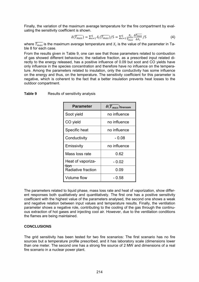
Finally, the variation of the maximum average temperature for the fire compartment by eval-uating the sensitivity coefficient is shown.
5��678------� = ∑ 5.��678------�/5�.;( = ∑ <=>%?-------
@>%?-------@<= /5�.;( (4)
where �678------is the maximum average temperature and B. is the value of the parameter in Ta-ble 8 for each case. From the results given in Table 9, one can see that those parameters related to combustion of gas showed different behaviours: the radiative fraction, as a prescribed input related di-rectly to the energy released, has a positive influence of 0.09 but soot and CO yields have only influence in the species concentration and therefore have no influence on the tempera-ture. Among the parameters related to insulation, only the conductivity has some influence on the energy and thus, on the temperature. The sensitivity coefficient for this parameter is negative, which is coherent to the fact that a better insulation prevents heat losses to the outdoor compartment. Table 9 Results of sensitivity analysis
Parameter C�DEFG-------�fireroom
Soot yield no influence
CO yield no influence
Specific heat no influence
Conductivity - 0.08
Emissivity no influence
Mass loss rate 0.62
Heat of vaporiza-tion
- 0.02
Radiative fraction 0.09
Volume flow - 0.58
The parameters related to liquid phase, mass loss rate and heat of vaporization, show differ-ent responses both qualitatively and quantitatively. The first one has a positive sensitivity coefficient with the highest value of the parameters analysed, the second one shows a weak and negative relation between input values and temperature results. Finally, the ventilation parameter shows a negative role, contributing to the cooling of the gas through the continu-ous extraction of hot gases and injecting cool air. However, due to the ventilation conditions the flames are being maintained. CONCLUSIONS The grid sensitivity has been tested for two fire scenarios: The first scenario has no fire sources but a temperature profile prescribed, and it has laboratory scale (dimensions lower than one meter. The second one has a strong fire source of 2 MW and dimensions of a real fire scenario in a nuclear power plant.
214

From the mesh sensitivity study it has been concluded that if radiation is the main factor to heat transfer, gas temperature is accurate enough with significantly large cell sizes. Howev-er, the temperatures of the other compartment components need a sensitivity analysis with smaller cell sizes. On the other hand, if there are fire sources and thus plume effects, the sensitivity of gas temperature against mesh size needs to be analysed. If that is not the case, larger errors may occur and, because of that, large real scenarios need to be carefully treated when mesh size is selected. For example, a common cell size when large areas are simulated is 0.2 m, however as results show, this one could be of little accuracy if the char-acteristic fire diameter is about a car fire (2 MW). Regarding parameters sensitivity, it is important to fix the goals of simulation since they pro-vide the criteria under which the sensitivity of the model is being analysed and for that, we will know which parameters have to be used with special care and which ones can be avoid-ed from the analysis. The parameters that have shown to be more sensitive from the analy-sis of the PRISME test facility are those related to heat release rate and mass flow ventila-tion in case that temperature prediction is the goal. However, it is necessary to analyse each criterion in terms of sensitivity to achieve the safety goals. ACKNOWLEDGEMENTS The authors want to thank the CSN (Nuclear Safety Council) for the collaboration and co-founding of the project “Fire modelling in nuclear power plants” under which this work has been performed. Moreover, they acknowledge the work performed within the OECD PRISME Project, without which the analytical work would not have been possible. REFERENCES [1] McGrattan, K., et al., Fire Dynamics Simulator User’s Guide, NIST Special Publication
1019, Sixth Edition, National Institute of Standards and Technology (NIST), Gaithersburg, MD, USA, 2013, http://dx.doi.org/10.6028/NIST.SP.1019.
[2] United States Nuclear Regulatory Commission (U.S. NRC), Office of Nuclear Regulato-ry Research (RES), and Electric Power Research Institute (EPRI), Verification and Vali-dation of Selected Fire Models for Nuclear Power Plant Applications, Volume 7: Fire Dynamics Simulator (FDS), Final Report, NUREG-1824 and EPRI 1011999, Washing-ton, DC, and Palo Alto, CA, USA, May 2007, http://pbadupws.nrc.gov/docs/ML0717/ML071730543.pdf.
[3] Hostikka, S., Developement of fire simulation models for radiative heat transfer and probabilistic risk assessment, doctoral thesis, Helsinki University of Technology, VTT publications 683, Espoo, Finland, 2008, http://www.vtt.fi/inf/pdf/publications/2008/P683.pdf.
[4] Najm, H. N., “Uncertainty Quantification and Polynomial Chaos Techniques in Computa-tional Fluid Dynamics”, Annual Review of Fluid Mechanics, 41(1), 2009, pp. 35-52.
[5] Suard, S., S. Hostikka, J. Baccou, “Sensitivity analysis of fire models using a fractional factorial design”, Fire Safety Journal, Volume 62, Part B, November 2013, pp. 115-124, http://dx.doi.org/10.1016/j.firesaf.2013.01.031.
[6] Nowlen, S. P., F.J. Wyant, Cable Response to Live Fire (CAROLFIRE), Volume 2: Ca-ble Fire Response Data for Fire Model Improvement, NUREG/CR-6931, Vol.2 and SAND2007-600/V2, United States Nuclear Regulatory Commission (U.S. NRC), Office of Nuclear Regulatory Research (RES) and Sandia National Laboratories (SNL), Albu-querque, NM, USA, April 2008, http://pbadupws.nrc.gov/docs/ML0811/ML081190248.pdf
215

[7] https://code.google.com/p/fds-smv/source/browse/trunk/FDS/trunk/Validation, last re-visted, July 2015.
[8] United States Nuclear Regulatory Commission (U.S. NRC), Office of Nuclear Regulato-ry Research (RES), and Electric Power Research Institute (EPRI), Nuclear Power Plant Fire Modeling Applications Guide (NPP FIRE MAG), Final Report, NUREG-1934 and EPRI 1023259, Washington, DC, and Palo Alto, CA, USA, November 2012, http://www.nrc.gov/reading-rm/doc-collections/nuregs/staff/sr1934/
[9] Morris, M. D., “Factorial sampling plans for preliminary computational experiments”, Technometrics 33, 1991, pp. 161-174.
216

23rd International Conference on Structural Mechanics in Reactor Technology (SMiRT 23) - 14th
International Post-Conference Seminar on “FIRE SAFETY IN NUCLEAR POWER PLANTS AND INSTALLATIONS“
FOCUS ON THE STUDIES IN SUPPPORT OF FIRE SAFETY ANALYSIS:
IRSN MODELLING APPROACH FOR NUCLEAR FACILITIES
Julien Espargillière, Raphaël Meyrand, Thierry Vinot
Institut de Radioprotection et de Sûreté Nucléaire (IRSN), Fontenay-aux-Roses, France
ABSTRACT For a fire safety analysis, in order to comply with nuclear safety goals, a nuclear fuel facility operator has to define the elements important for safety to be maintained, even in the case of a fire. One of the key points of this fire analysis is the assessment of possible fire scenari-os in the facility. This paper presents the IRSN method applied to a case study to assess fire scenarios which have the most harmful effects on safety targets. The layout consists in a central room (fire cell) containing three glove boxes with radioactive material and three elec-trical cabinets. This room is linked to two connecting compartments (the fire cell and these two compartments define the containment cell) and then to two corridors. Each room is equipped with a mechanical ventilation system, and a pressure cascade is established from the corridors to the central room. A fire scenario was studied with fire ignition occurring in an electrical cabinet. This scenario has a set of safety goals (prevention of fire cell and con-tainment device failure, propagation of the fire). This case study was conducted with the IRSN code SYLVIA based on two zones modelling. Safety goals were associated with key parameters and performance criteria to be fulfilled. Modelling assumptions were defined in order to maximize physical effects of the fire. Sensitivity studies were also conducted on key parameters such as oxygen limitation, equivalent-fuel definition. Eventually, a critical analy-sis of the code models was carried out. INTRODUCTION Over several years now, the French nuclear fire safety regulation [1] and [2] has turned from prescriptive to objective requirements. Consequently, the fire safety analysis (FSA) focuses now on the compliance of fire effects with performance criteria for fire protection measures. These performance criteria are mainly related to the vulnerability of targets (for instance, containment equipment) within nuclear fuel facilities in order to avoid accidental sequences potentially compromising facility safety functions and leading to a significant release of nu-clear materials in environment. To assess this demonstration in its FSA, the licensee has to ensure that nuclear safety objectives are fulfilled in the case of accidental fires. A key step in this analysis process is the identification of the targets associated to the elements important for safety to be maintained. These targets may include structural elements, all types of nu-clear systems and various components important to nuclear safety. Furthermore, the protec-tion of employees who have to ensure safety operations for nuclear facilities must also be considered. The last step of the analysis consists in the evaluation of the effects of a fire on targets, performed with numerical simulations. To illustrate this method, a case-study of a typical containment cell of a nuclear fuel facility is presented below. This cell contains both electrical equipment and radioactive materials. For this case-study, the fire safety analysis highlights a scenario in which fire starts in an open-door electrical cabinet facing the glove boxes. In order to assess the fire consequences for this scenario, a series of fire simulations was carried out with the SYLVIA fire simulation code [3] developed by IRSN (Institut de Radiopro-
217

tection et de Sûreté Nucléaire). This fire code is based on a two-zone modelling approach [3] and [4] to calculate smoke and heat transfers from fire source to other compartments or ven-tilation network and the impact on targets. The results from theses computations allowed the accurate identification of all the important safety equipment that could potentially be dam-aged by fire consequences. To properly perform these fire simulations and predict the rele-vant target damages, IRSN needs to establish fire properties and rupture criteria of contain-ment equipment by means of both experimental tests and literature data:
fire source characteristics (heat release rate (HRR), fire growth, mass loss rate, combustion products, etc.) based on open fire tests representative of fire scenarios in facilities,
rupture criteria of containment equipment (gloves, doors, pipes, etc.) due to pres-sure and heat stresses,
fire spreading criteria for electrical cabinets or glove boxes.
After this introduction, a complete description of the case-study is detailed. Then, some ex-perimental tests performed at IRSN are presented concerning the determination of charac-teristics of electrical cabinet fire, glove box fire and rupture criteria of containment equip-ment. From these experimental outcomes and a dataset (geometry, ventilation network, etc.) describing the case-study, the criteria related to the safety issues, the fire modelling and the key assumptions needed for the calculations by means of SYLVIA fire code are detailed. A discussion is proposed about the computations results before concluding this paper. CASE STUDY DESCRIPTION The case study is a typical containment cell of a nuclear fuel facility. This cell contains both electrical equipment and radioactive materials. A full description of the fire cell is presented in Figure 1 and Figure 2. The fire compartment includes a row of three electrical cabinets which powers equipment important for safety. This room also includes three glove boxes containing radioactive mate-rials and facing the cabinet row at a distance of 1.5 m. This room is linked with the rest of the facility by two connecting zones. In a simplified manner, the rest of the facility is represented by two large corridors. The fire compartmentation only includes the fire compartment and the fire resistance rating according to the standard nominal fire curve from ISO-834 [5] being 90 min. Every room is equipped with a nuclear ventilation system. To prevent radioactive material dispersal, inlet air vents are located near the ceiling and exhaust air vents near the floor. The containment compartmentation consists in the room itself and the two connecting zones; the pressure drops between rooms have to be kept to ensure the dynamic contain-ment. The glove boxes are composed of four metal panels and two opposite “working” panels of LEXAN (polycarbonate polymer, 10 mm thick) with a biological protection in leaded PMMA (polymethyl methacrylate, 50 mm thick). Four glove holes in each “working” panel allow op-erators handling. One of these “working” panels is facing the cabinet row. The glove box ventilation is made of vertical PVC pipes routed from the ceiling. In case of fire, a safety interlock closes the fire room dampers on ventilation inlets and ex-hausts after fire detection. A detection time of 2 min 30 s after the ignition is assumed. The ventilation of connecting zones and corridors is maintained.
218
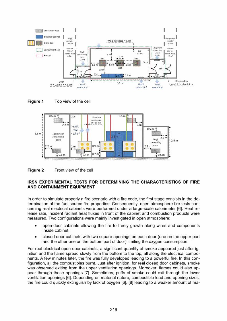
Figure 1 Top view of the cell
Figure 2 Front view of the cell IRSN EXPERIMENTAL TESTS FOR DETERMINING THE CHARACTERISTICS OF FIRE AND CONTAINMENT EQUIPMENT In order to simulate properly a fire scenario with a fire code, the first stage consists in the de-termination of the fuel source fire properties. Consequently, open atmosphere fire tests con-cerning real electrical cabinets were performed under a large-scale calorimeter [6]. Heat re-lease rate, incident radiant heat fluxes in front of the cabinet and combustion products were measured. Two configurations were mainly investigated in open atmosphere:
open-door cabinets allowing the fire to freely growth along wires and components inside cabinet,
closed door cabinets with two square openings on each door (one on the upper part and the other one on the bottom part of door) limiting the oxygen consumption.
For real electrical open-door cabinets, a significant quantity of smoke appeared just after ig-nition and the flame spread slowly from the bottom to the top, all along the electrical compo-nents. A few minutes later, the fire was fully developed leading to a powerful fire. In this con-figuration, all the combustibles burnt. Just after ignition, for real closed door cabinets, smoke was observed exiting from the upper ventilation openings. Moreover, flames could also ap-pear through these openings [7]. Sometimes, puffs of smoke could exit through the lower ventilation openings [6]. Depending on material nature, combustible load and opening sizes, the fire could quickly extinguish by lack of oxygen [6], [8] leading to a weaker amount of ma-
219
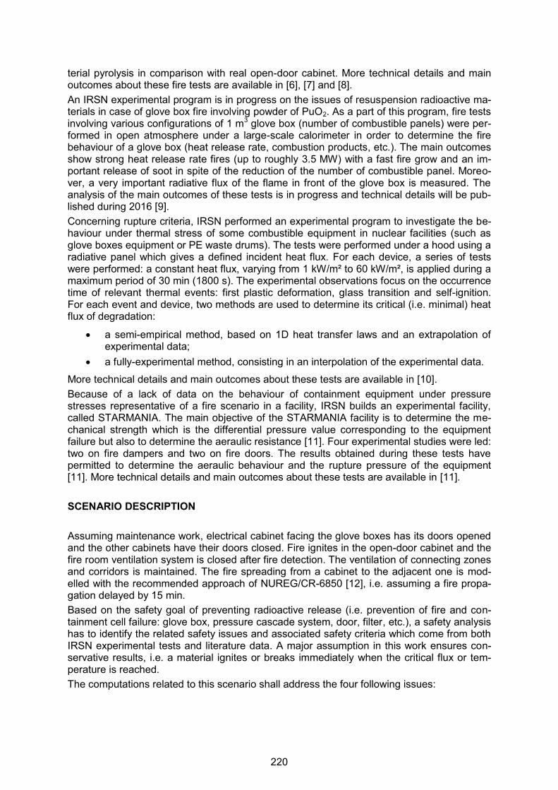
terial pyrolysis in comparison with real open-door cabinet. More technical details and main outcomes about these fire tests are available in [6], [7] and [8]. An IRSN experimental program is in progress on the issues of resuspension radioactive ma-terials in case of glove box fire involving powder of PuO2. As a part of this program, fire tests involving various configurations of 1 m3 glove box (number of combustible panels) were per-formed in open atmosphere under a large-scale calorimeter in order to determine the fire behaviour of a glove box (heat release rate, combustion products, etc.). The main outcomes show strong heat release rate fires (up to roughly 3.5 MW) with a fast fire grow and an im-portant release of soot in spite of the reduction of the number of combustible panel. Moreo-ver, a very important radiative flux of the flame in front of the glove box is measured. The analysis of the main outcomes of these tests is in progress and technical details will be pub-lished during 2016 [9]. Concerning rupture criteria, IRSN performed an experimental program to investigate the be-haviour under thermal stress of some combustible equipment in nuclear facilities (such as glove boxes equipment or PE waste drums). The tests were performed under a hood using a radiative panel which gives a defined incident heat flux. For each device, a series of tests were performed: a constant heat flux, varying from 1 kW/m² to 60 kW/m², is applied during a maximum period of 30 min (1800 s). The experimental observations focus on the occurrence time of relevant thermal events: first plastic deformation, glass transition and self-ignition. For each event and device, two methods are used to determine its critical (i.e. minimal) heat flux of degradation:
a semi-empirical method, based on 1D heat transfer laws and an extrapolation of experimental data;
a fully-experimental method, consisting in an interpolation of the experimental data.
More technical details and main outcomes about these tests are available in [10]. Because of a lack of data on the behaviour of containment equipment under pressure stresses representative of a fire scenario in a facility, IRSN builds an experimental facility, called STARMANIA. The main objective of the STARMANIA facility is to determine the me-chanical strength which is the differential pressure value corresponding to the equipment failure but also to determine the aeraulic resistance [11]. Four experimental studies were led: two on fire dampers and two on fire doors. The results obtained during these tests have permitted to determine the aeraulic behaviour and the rupture pressure of the equipment [11]. More technical details and main outcomes about these tests are available in [11]. SCENARIO DESCRIPTION Assuming maintenance work, electrical cabinet facing the glove boxes has its doors opened and the other cabinets have their doors closed. Fire ignites in the open-door cabinet and the fire room ventilation system is closed after fire detection. The ventilation of connecting zones and corridors is maintained. The fire spreading from a cabinet to the adjacent one is mod-elled with the recommended approach of NUREG/CR-6850 [12], i.e. assuming a fire propa-gation delayed by 15 min. Based on the safety goal of preventing radioactive release (i.e. prevention of fire and con-tainment cell failure: glove box, pressure cascade system, door, filter, etc.), a safety analysis has to identify the related safety issues and associated safety criteria which come from both IRSN experimental tests and literature data. A major assumption in this work ensures con-servative results, i.e. a material ignites or breaks immediately when the critical flux or tem-perature is reached. The computations related to this scenario shall address the four following issues:
220

Issue a: Does cabinet fire cause a loss of containment of glove boxes? Gloves rupture (named [G] in the results tables) is assumed if a thermal flux of 2 kW/m² [10] or a temperature of 85 °C [13] is reached. Ventilation PVC pipes rupture (named [V] in the results tables) is assumed if a thermal flux of 4 kW/m² [10] or a temperature of 125 °C [13] is reached.
Issue b: Does fire spread from cabinets to glove boxes? Due to lack of data, leaded PMMA is assumed to behave like PMMA. Therefore, an igni-tion flux of 15 kW/m² [14], a material ignition temperature of 250 °C [14] for PMMA (named [P] in the results tables) or an ambient gas temperature of 500 °C, correspond-ing to flashover conditions (named [F] in the results tables), are assumed. The fire spread to working panel is assumed if PMMA panel ignites. If fire spreads to glove box-es, the effects of these secondary fires must be taken into account.
Issue c: Does fire cause a failure of fire compartmentation? The calculations have to determine if a fire can last longer than 90 min (named [D] in the results tables) or if the gas temperature exceeds the standard nominal fire curve ISO-834 (named [G] in the results tables).
Issue d: Does fire cause a failure of containment cell? The computations have to determine if a fire cause a pressure cascade inversion (named [R] in the results tables) or a double-door rupture (named [D] in the results ta-bles). These rupture is assumed if door pressure gap exceed 18 hPa [11].
FIRE SIMULATIONS: NUMERICAL TOOLS, ROOMS AND FIRE MODELING Numerical Too The SYLVIA software system [3], developed by IRSN, is designed to simulate the fire growth and its consequences in an industrial facility featuring a ventilation network. SYLVIA particu-larly calculates the development of the fire, the transportation of hot gases and soot, the transportation of aerosols (whether radioactive or not), the clogging of filters, the environ-mental conditions inducing the failure of electrical equipment and the mechanical damage on fire barriers such as firebreak doors and fire dampers. Based on a two-zone modelling, each compartment is divided into two zones of variable volume, in which the thermodynamic properties are uniform (temperature, combustion products, etc.). The ventilation network is modelled using a set of elements, such as ducts, filters, valves, fans, etc. Mass and heat ex-change correlations (between zones, flames and walls) supplies the mass and energy bal-ance equations performed in each zone. This software is especially designed to perform low time consuming simulations that are required for safety assessments. Modelling the Fire Source: How to Model Fire Spreading from One Electrical Cabinet to Adjacent Ones For this study, the fire source is considered to be a row of three electrical cabinets. The first cabinet of the row, where fire breaks out, is assumed open-door. For other cabinets, their doors are closed. Based on realistic approach, the time evolutions of HRR for open and closed-door cabinets are taken from the IRSN fire tests which could lead to the most harmful effects on safety issues (CA02 test in [8] for closed door cabinet and PXA.3.2 in [6] for open-door cabinet). Moreover, the fire spread between cabinets is assumed all along the cabinet row. Consequently, the total heat release rate sums the different HRR for each single cabi-net already in fire. The fire spread from a cabinet to the adjacent one is modelled with the recommended approach of NUREG/CR-6850 [12], i.e. assuming fire propagation delayed by
221
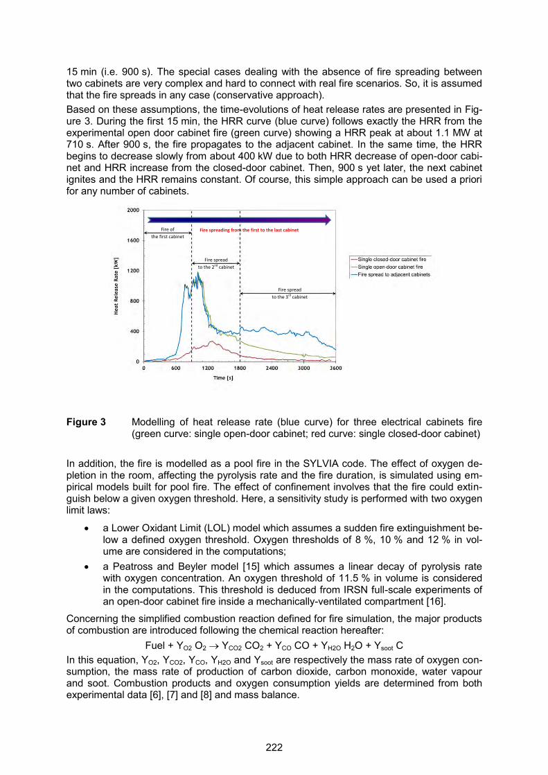
15 min (i.e. 900 s). The special cases dealing with the absence of fire spreading between two cabinets are very complex and hard to connect with real fire scenarios. So, it is assumed that the fire spreads in any case (conservative approach). Based on these assumptions, the time-evolutions of heat release rates are presented in Fig-ure 3. During the first 15 min, the HRR curve (blue curve) follows exactly the HRR from the experimental open door cabinet fire (green curve) showing a HRR peak at about 1.1 MW at 710 s. After 900 s, the fire propagates to the adjacent cabinet. In the same time, the HRR begins to decrease slowly from about 400 kW due to both HRR decrease of open-door cabi-net and HRR increase from the closed-door cabinet. Then, 900 s yet later, the next cabinet ignites and the HRR remains constant. Of course, this simple approach can be used a priori for any number of cabinets.
Figure 3 Modelling of heat release rate (blue curve) for three electrical cabinets fire
(green curve: single open-door cabinet; red curve: single closed-door cabinet) In addition, the fire is modelled as a pool fire in the SYLVIA code. The effect of oxygen de-pletion in the room, affecting the pyrolysis rate and the fire duration, is simulated using em-pirical models built for pool fire. The effect of confinement involves that the fire could extin-guish below a given oxygen threshold. Here, a sensitivity study is performed with two oxygen limit laws:
a Lower Oxidant Limit (LOL) model which assumes a sudden fire extinguishment be-low a defined oxygen threshold. Oxygen thresholds of 8 %, 10 % and 12 % in vol-ume are considered in the computations;
a Peatross and Beyler model [15] which assumes a linear decay of pyrolysis rate with oxygen concentration. An oxygen threshold of 11.5 % in volume is considered in the computations. This threshold is deduced from IRSN full-scale experiments of an open-door cabinet fire inside a mechanically-ventilated compartment [16].
Concerning the simplified combustion reaction defined for fire simulation, the major products of combustion are introduced following the chemical reaction hereafter:
Fuel + YO2 O2 YCO2 CO2 + YCO CO + YH2O H2O + Ysoot C In this equation, YO2, YCO2, YCO, YH2O and Ysoot are respectively the mass rate of oxygen con-sumption, the mass rate of production of carbon dioxide, carbon monoxide, water vapour and soot. Combustion products and oxygen consumption yields are determined from both experimental data [6], [7] and [8] and mass balance.
Fire of
the first cabinet
Fire spread
to the 2nd cabinet
Fire spread
to the 3rd cabinet
Fire spreading from the first to the last cabinet
222
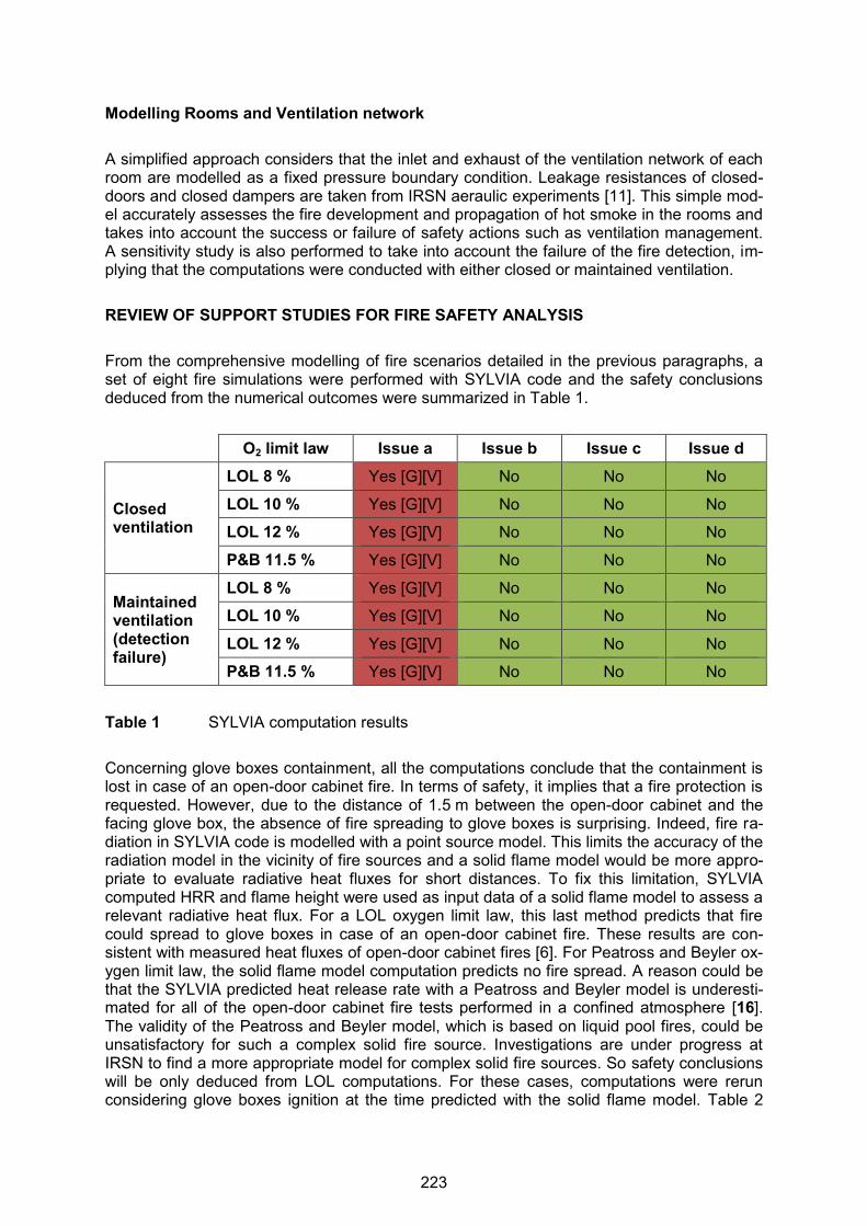
Modelling Rooms and Ventilation network A simplified approach considers that the inlet and exhaust of the ventilation network of each room are modelled as a fixed pressure boundary condition. Leakage resistances of closed-doors and closed dampers are taken from IRSN aeraulic experiments [11]. This simple mod-el accurately assesses the fire development and propagation of hot smoke in the rooms and takes into account the success or failure of safety actions such as ventilation management. A sensitivity study is also performed to take into account the failure of the fire detection, im-plying that the computations were conducted with either closed or maintained ventilation. REVIEW OF SUPPORT STUDIES FOR FIRE SAFETY ANALYSIS From the comprehensive modelling of fire scenarios detailed in the previous paragraphs, a set of eight fire simulations were performed with SYLVIA code and the safety conclusions deduced from the numerical outcomes were summarized in Table 1.
O2 limit law Issue a Issue b Issue c Issue d
Closed ventilation
LOL 8 % Yes [G][V] No No No
LOL 10 % Yes [G][V] No No No
LOL 12 % Yes [G][V] No No No
P&B 11.5 % Yes [G][V] No No No
Maintained ventilation (detection failure)
LOL 8 % Yes [G][V] No No No
LOL 10 % Yes [G][V] No No No
LOL 12 % Yes [G][V] No No No
P&B 11.5 % Yes [G][V] No No No
Table 1 SYLVIA computation results Concerning glove boxes containment, all the computations conclude that the containment is lost in case of an open-door cabinet fire. In terms of safety, it implies that a fire protection is requested. However, due to the distance of 1.5 m between the open-door cabinet and the facing glove box, the absence of fire spreading to glove boxes is surprising. Indeed, fire ra-diation in SYLVIA code is modelled with a point source model. This limits the accuracy of the radiation model in the vicinity of fire sources and a solid flame model would be more appro-priate to evaluate radiative heat fluxes for short distances. To fix this limitation, SYLVIA computed HRR and flame height were used as input data of a solid flame model to assess a relevant radiative heat flux. For a LOL oxygen limit law, this last method predicts that fire could spread to glove boxes in case of an open-door cabinet fire. These results are con-sistent with measured heat fluxes of open-door cabinet fires [6]. For Peatross and Beyler ox-ygen limit law, the solid flame model computation predicts no fire spread. A reason could be that the SYLVIA predicted heat release rate with a Peatross and Beyler model is underesti-mated for all of the open-door cabinet fire tests performed in a confined atmosphere [16]. The validity of the Peatross and Beyler model, which is based on liquid pool fires, could be unsatisfactory for such a complex solid fire source. Investigations are under progress at IRSN to find a more appropriate model for complex solid fire sources. So safety conclusions will be only deduced from LOL computations. For these cases, computations were rerun considering glove boxes ignition at the time predicted with the solid flame model. Table 2
223
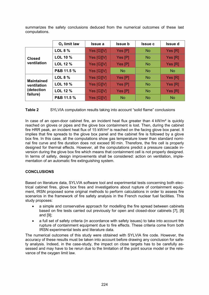
summarizes the safety conclusions deduced from the numerical outcomes of these last computations.
O2 limit law Issue a Issue b Issue c Issue d
Closed ventilation
LOL 8 % Yes [G][V] Yes [P] No Yes [R]
LOL 10 % Yes [G][V] Yes [P] No Yes [R]
LOL 12 % Yes [G][V] Yes [P] No Yes [R]
P&B 11.5 % Yes [G][V] No No No
Maintained ventilation (detection failure)
LOL 8 % Yes [G][V] Yes [P] No Yes [R]
LOL 10 % Yes [G][V] Yes [P] No Yes [R]
LOL 12 % Yes [G][V] Yes [P] No Yes [R]
P&B 11.5 % Yes [G][V] No No No
Table 2 SYLVIA computation results taking into account “solid flame” conclusions In case of an open-door cabinet fire, an incident heat flux greater than 4 kW/m² is quickly reached on gloves or pipes and the glove box containment is lost. Then, during the cabinet fire HRR peak, an incident heat flux of 15 kW/m² is reached on the facing glove box panel. It implies that fire spreads to the glove box panel and the cabinet fire is followed by a glove box fire. In this case, all the computations show gas temperature lower than standard nomi-nal fire curve and fire duration does not exceed 90 min. Therefore, the fire cell is properly designed for thermal effects. However, all the computations predict a pressure cascade in-version during the glove box fire which means that containment cell is not properly designed. In terms of safety, design improvements shall be considered: action on ventilation, imple-mentation of an automatic fire extinguishing system. CONCLUSIONS Based on literature data, SYLVIA software tool and experimental tests concerning both elec-trical cabinet fires, glove box fires and investigations about rupture of containment equip-ment, IRSN proposed some original methods to perform calculations in order to assess fire scenarios in the framework of fire safety analysis in the French nuclear fuel facilities. This study proposes:
a simple and conservative approach for modelling the fire spread between cabinets based on fire tests carried out previously for open and closed-door cabinets [7], [8] and [9];
a full set of safety criteria (in accordance with safety issues) to take into account the rupture of containment equipment due to fire effects. These criteria come from both IRSN experimental tests and literature data.
The numerical outcomes of this study were obtained with SYLVIA fire code. However, the accuracy of these results must be taken into account before drawing any conclusion for safe-ty analysis. Indeed, in the case-study, the impact on close targets has to be carefully as-sessed and may have to be rerun due to the limitation of the point source model or the rele-vance of the oxygen limit law.
224
REFERENCES [1] Vinot T., The IRSN approach on fire safety analysis of nuclear facilities, Six Country
Meeting on Fire Safety in Nuclear Installations, Garching, Germany, 30th April 2013. [2] Vinot T., Y. Ormieres, and J. Lacoue, “IRSN global process for conducting a compre-
hensive fire safety analysis for nuclear installations”, in; Röwekamp, M., H.-P. Berg (Eds.): Proceedings of SMiRT 22, 13th International Seminar on Fire Safety in Nuclear Power Plants and Installations, September 18-20, 2013, Columbia, SC, USA, GRS-A-3731, Gesellschaft für Anlagen- und Reaktorsicherheit (GRS) mbH, Köln, Germany, Dezember 2013, http://www.grs.de/sites/default/files/pdf/grs-a-3731.pdf.
[3] Audouin L., et al., Quantifying differences between computational results and meas-urements in the case of a large-scale well-confined fire scenario, Nuclear Engineering and Design 241, pp. 18-31, 2011.
[4] Karlsson B., and J. Quintiere, Enclosure Fire Dynamics, CRC Press, 2000. [5] International Organization of Standardization (ISO) (Ed.), ISO 834-1: Fire-resistance
tests - Elements of building construction - Part 1: General requirements, Geneva, Swit-zerland, 1999, http://www.iso.org/iso/home/store/catalogue_tc/catalogue_detail.htm?csnumber=2576.
[6] Coutin, M., et al., “Phenomenological description of actual electrical cabinet fires in a free atmosphere”, Proceedings of 11th INTERFLAM, 2007, http://www.irsn.fr/EN/Research/publications-documentation/Publications/DPAM/SEREA/Pages/Phenomenological-description-of-actual-electrical-cabinet-fires-in-a-free-atmosphere-3938.aspx.
[7] Rigollet, L., S. Melis, “Heat release rate of vertical combustibles inside a confinement: An analytical approach to the fire of electrical cabinets”, Proceedings of 11th INTERFLAM, 2007,http://www.irsn.fr/EN/Research/publications-documentation/Publications/DPAM/SEREA/Pages/Heat-release-rate-of-vertical-combustibles-inside-a-confinement-an-analytical-approach-to-the-fire-of-2372.aspx.
[8] Plumecocq, W., et al., “Characterization of closed-doors electrical cabinet fires in com-partments”, Fire Safety Journal, Volume 46, 2011, pp. 243-253, http://www.sciencedirect.com/science/article/pii/S0379711211000385#.
[9] Coutin, M., Behaviour of a glove box fire (provisional title), to be published, 2016. [10] Piller, M., et al., “Experimental study of thermal degradation of some nuclear materials
under a radiative thermal stress” (French version), 14èmes Journées Internationales de Thermique, Djerba, 2009.
[11] Bouilloux, L., et al., Characterisation of the Behaviour of Containment Equipment under Mechanical and Thermal Stresses in STARMANIA Facility, EUROSAFE, 2003
[12] Electric Power Research Institute (EPRI) and United States Nuclear Regulatory Com-mission Office of Nuclear Research (NRC-RES), Fire PRA Methodology for Nuclear Power Facilities, EPRI/NRC-RES, Final Report, Volume 1 and 2, EPRI 1011989, NUREG/CR-6850, Palo Alto, CA, USA, September 2005, http://www.nrc.gov/reading-rm/doc-collections/nuregs/contract/cr6850/.
[13] Mark, J. E., Physical Properties of Polymer Handbook, Springer 2nd ed., 2007. [14] Rhodes, B. T., Burning rate and flame heat flux for PMMA in the cone calorimeter, Re-
port NIST-GCR-95-664, National Institute of Standards and Technology (NIST), Gaithersburg, MD, USA, 1994, http://fire.nist.gov/bfrlpubs/fire94/PDF/f94012.pdf.
[15] Peatross, M. J. and C. L. Beyler, “Ventilation effect on compartment fire characteriza-tion”, Fire Safety Science, Proceedings of 5th international symposium, 1996, pp. 403-414.
[16] Coutin, M., et al., “Characterisation of open-door electrical cabinet fires in compart-ments”, Nuclear Engineering and Design, 286, 2015, pp. 104-115.
225
23rdInternational Conference on Structural Mechanics in Reactor Technology (SMiRT 23) - 14h
International Post-Conference Seminar on “FIRE SAFETY IN NUCLEAR POWER PLANTS AND INSTALLATIONS“
FIRE ANALYSIS: RELEVANT ASPECTS FROM SPANISH NUCLEAR POWER PLANTS EXPERIENCE
Pedro Fernández1, Tómas Villar1
1 Empresarios Agrupados A.I.E., Nuclear Safety Department, Madrid, Spain
ABSTRACT Empresarios Agrupados A.I.E. leads the development and updating of fire analysis for the Spanish NPP's. Some of them decided to voluntarily adopt standard NFPA-805 [1] as an al-ternative to the current fire protection rules. Fire Probabilistic Risk Assessment (PRA) meth-odologies have been continuously evolving during recent years. This paper will briefly pre-sent experience gained in relationship with some relevant aspects of fire risk analysis. Associated circuits need to be evaluated to determine if cable faults can prevent or cause the maloperation of redundant safety related systems. If a circuit is not properly protected by an isolation device, fire damage to a cable could propagate to other safe shutdown cables. In order to check that the coordination is adequate, existing electrical protections coordina-tion studies have been analyzed and, for some plants, additional analyses have been per-formed for DC and AC for instrumentation an control (I&C) systems. Spurious actuations are also a basic part of the analysis of the consequence of a fire, which should consider any possible actuation that can prevent or affect the performance of a sys-tem or safety function. In this context, it was furthermore necessary to take into account the possibility of a combination of several spurious actuations that can result in a specific conse-quence, according to Appendix G of NEI 00-01 Rev. 2 [2]. These are the so-called Multiple Spurious Operations (MSOs). One key element in fire analysis is the availability of validated fire models used to estimate the spread of fire and the failure time of cable raceways. NFPA 805 [1] states that fire mod-els shall only be applied within the limitations of the given model. The applicability of the val-idation results is determined using normalized parameters traditionally used in fire modeling applications. Normalized parameters assessed in NUREG-1934 [3] may be used to compare NPP fire scenarios with validation experiments. If some of the parameters do not fall within the range of the study, further justification must be made. Additionally, in order to compare the results and to check that the semi-empirical equations described in NUREG-1805 [4] lead to conservative results, some calculations for a few fire zones were performed using the more accurate CFD model "Fire Dynamics Simulator" (FDS). As a result of Human Reliability Analysis, more complete and accurate information about equipment and instrumentation that can fail due to a fire in the different fire areas will be pro-vided to the operators in order to assure them about the equipment they can rely on in case of fire, thus helping them respond better to a plant transient caused by the fire. As part of the transition process to NFPA-805, an estimation has been performed of the in-crease in risk associated with non-compliance with Appendix R of 10 CFR 50 [5], for both Core Damage Frequency (CDF) and Large Early Release Frequency (LERF), in order to de-termine its acceptability within the criteria established in the Regulatory Guide 1.174 [6].
226

CONTENT OF THE PAPER
1 INTRODUCTION
2 EVALUATION OF ASSOCIATED CIRCUITS
3 VALIDATION OF FIRE MODELS (FDT’s)
4 COMPARISON OF FDS AND FDT’s FIRE GROWTH CALCULATIONS
5 INFORMATION GIVEN TO THE OPERATOR AS A CONSEQUENCE OF FIRE ANALYSIS
6 INCREASE IN RISK CALCULATIONS
7 CONCLUSIONS INTRODUCTION Fire Probabilistic Risk Assessment (PRA) methodologies have been continuously evolving during recent years. Empresarios Agrupados, A.I.E. leads the development and updating of fire analysis for the Spanish NPP's. Some of them decided to voluntarily adopt standard NFPA-805 [1] as an al-ternative to the current fire protection rules.
Almaraz I/II NPP. Analyzes performed as part of the transition process to NFPA 805 [1]. Peer review for fire PRA performed in February 2011.
Ascó I/II NPP. Analyzes performed as part of the transition process to NFPA 805 [1]. Peer review for fire PRA performed in June 2015.
Vandellós II NPP. Analyzes performed as part of the Periodic Safety Review. Trillo I NPP. Analyzes performed as part of the Periodic Safety Review.
The baseline methodology described in NUREG/CR-6850 [7] has been used to perform the fire Probabilistic Risk Assessment, taking into account the Frequently Asked Questions that have been released over these years and also the Supplements of NUREG/CR-6850 [7] (general fire PRA methodology) and NUREG-1805 [4] (fire growth calculations). Some relevant aspects derived from this experience are highlighted with relation to associ-ated circuits of concern, fire models, operation and increase in risk calculations. EVALUATION OF ASSOCIATED CIRCUITS Both NEI 00-01 [2] and Generic Letter 81-12 [8] define associated circuits of concern as those cables and equipment that have a physical separation less than that required by Sec-tion III.G.2 of Appendix R [5], and have either: a) a common power source with the shutdown equipment and the power source is not electrically protected from the circuit of concern by coordinated breakers, fuses, or similar devices, b) a connection to circuits of equipment whose spurious operation would adversely affect the shutdown capability and c) a common enclosure with the shutdown cables not electrically protected with the possibility of not pre-venting propagation to it. This type of circuits needs to be evaluated to determine if cable faults can prevent or cause the maloperation of redundant safety related systems. For the circuits related to cases a) and c), in order to check that the coordination is ade-quate, coordination studies on electrical protections have been analyzed and, for some
227
plants, additional analyzes have been performed for DC and AC for instrumentation & con-trol systems. These analyzes help ensure that the electrical protections on the different loads of the plant are appropriate and coordination between different levels of protection works adequately with regard to AC and DC for instrumentation & control systems. These studies show that the impact of circuits that share a power source or electrical race-ways is adequately contemplated in the design, and that no further action is therefore con-sidered necessary within fire analyses. For the circuits in case b), the analysis of each fire area identifies all the affected compo-nents, either because they failed when performing their active function or because they may undergo spurious operation. Fire-induced spurious operation is an event where the fire causes damage to the cables so that a given component changes to an undesired status that prevents or affects the perfor-mance of one or more safety functions. Since fires can affect several cables, the occurrence of more than one spurious operation during a fire can be contemplated. Combinations of spurious operation in different systems that could affect one or more safety functions have been taken into account. The concept of multiple spurious operations basically involves several spurious operations to coincide, which may occur under different conditions. Reference document NEI-00-01 Rev. 2 (Appendix G) [2] provides a list of multiple spurious operation (MSO’s) scenarios that fall into one of the above groups. These lists are based on the experience at similarly designed plants and are used as a basis for a systematic review of combinations of spurious operations that yield scenarios that differ from the ones consid-ered. Spanish nuclear power plants have been analyzed using the above document as a basis to identify any potential scenarios that have not been included in the analyzes. Their applicabil-ity and potential impact have been analyzed. In some plants, the applicability of the various multiple spurious operation (MSO) scenarios has been addressed in expert panels formed by PRA, electrical, instrumentation and me-chanical engineering specialists, as well as by operating personnel. These analyses have yielded the following results:
Several scenarios were already included in the PRA models; Some scenarios have been discarded because of the large number of spurious actua-
tions required or because of specific assumptions or calculations; Some scenarios have required additional malfunctions that were not initially included in
the models to be considered; Some scenarios have called for certain additional initiating events apart from those ini-
tially considered in the models; Some scenario resulting from the impossibility of accepting local recovery actions on
motor-operated valves. VALIDATION OF FIRE MODELS (FDT’s) One key element in fire analysis is the availability of validated fire models to estimate the spread of fire and the cable raceways failure time. This time is related to the time available for fire suppression. The calculations performed for the fire PRA analysis were based on the methodology de-scribed in NUREG/CR-6850 [7] and on the semi-empirical equations and correlations ex-plained in NUREG-1805 [4] (FDT’s Fire Dynamics Tools).
228
NFPA 805 [1] states that fire models shall only be applied within the limitations of the given model. The applicability of the validation results is determined using normalized parameters traditionally used in fire modeling applications. Normalized parameters assessed in NUREG-1934 [3] “Nuclear Power Plant Fire Modeling Analysis Guidelines” may be used to compare NPP fire scenarios with validation experiments. These parameters are the following:
Fire Froude Number: related to fire diameter and thus to plume temperature and flame height;
Flame length ratio: related to the “size” of the fire relative to the height of the zone; Ceiling Jet Distance Ratio which measures the ceiling jet position; Equivalence Ratio: which relates the heat release rate and the ventilation rate; Compartment Aspect Ratio which measures the general shape of the zone; Radial Distance Ratio: related to the radiative heat flux calculations.
If not all of the parameters fall within the range of the study, additional justification is neces-sary to be made, by means of performing sensitivity analysis. These analyzes refer to vary-ing selected input parameters in the “conservative” direction so that they fall within the ap-plicability range. If the conclusions (fire growth and CDF of the fire scenario) are not affected by the variations in the parameters, the sensitivity analysis results may be used to further justify the conclusions. The most relevant parameters outside the validation range for the fire growth calculations performed for fire PRA’s were shown to be the Fire Froude Number and the Radial Distance Ratio. For the former, the results of the validation for the heat release rates of the most common fire sources such as vertical cabinets (fire limited to only one cable bundle and fire in more than one cable bundle), electrical fires in pumps, motors, ventilation subsystems, transform-ers and transient combustibles are shown in Table 1 below. Table 1 Results of the validation in terms of the Fire Froude Number for the typical
Heat Release Rates of fire sources
HRR [kW] Minimum Valid Diameter [m]
Maximum Valid Diameter (m)
Diameter Used in the Model [m]
Valid
32 0.171 0.350 0.600 No
69 0.233 0.475 0.600 No
142 0.310 0.636 0.600 Yes
211 0.364 0.745 0.600 Yes 317 0.428 0.876 0.600 Yes 702 0.588 1.204 0.600 Yes
This means that the calculations for fires in motors, transformers and ventilation subsystems (for both severity factors 75 % and 98 %) and in one cable bundle vertical cabinets (for 75 % severity factor) are outside the validation range. A sensitivity analysis for these scenarios was carried out using a fire diameter of 0.350 m and 0.475 m, respectively. For the latter, the scenario would be within the validation range if the heat flux calculation ra-dius falls between 1.32 m and 3.42 m, assuming a fire “size” of 0.6 m.
229
Likewise, another sensitivity analysis for the few scenarios outside the validation range for the radial distance ratio was performed, assuming the failure of the cable trays involved in the conservative direction. Both sensitivity analyzes lead to a decrease in the time available for fire suppression, be-cause the flame height increases due to the decrease in the fire diameter, and thus the time in which the flame reaches the target diminishes, on the one hand, and if the target race-ways in the heat flux heat are deemed to be damaged in the conservative way, the time available for fire suppression decreases too. The typical reduction in the time available was shown to be approximately one minute or less. This might be relevant because a reduction of for example 40 seconds in the time available would lead to a 6 % increase in the non-suppression probability and so in the CDF. The results of the evaluation of the impact of these analyzes once validation criteria were used show that the increase in the total CDF is low, on the order of 1 – 2 %. This means that the conclusions of the fire PRA do not change significantly, but the results of the validation should be taken into account for the future revisions of the documentation. Nevertheless, a draft report of the Supplement 1 of NUREG-1824 [9] “Verification and Vali-dation of Selected Fire Models for Nuclear Power Plant Applications” released on November 2014 includes additional test data for validation of the models and suggests that the range of validation could widen, so that all calculations would meet the validation range. COMPARISON OF FDS AND FDT’S FIRE GROWTH CALCULATIONS The fire propagation calculations aim to determine the raceway (cable trays) failure time that could be affected by the fire. As shown before, the calculations were based on the method-ology described in NUREG/CR-6850 [7] and on the semi-empirical equations and correla-tions explained in NUREG-1805 [4]. These calculations are based on very conservative in many aspects empirical mathematical formulations, and do not include a realistic methodol-ogy for the calculation of some key parameters of the fire growth. To complement this, additional calculations for a few fire zones were made using the ad-vanced fluid dynamics computer code "Fire dynamics simulator" (FDS), which can perform more accurate estimations of the consequences of a fire. The goal of these calculations was to compare the results and to check that the semi-empirical equations described in NUREG-1805 [4] lead to conservative results. The parame-ters of the fire used in the simulations as well as the time evolution of HRR and damage cri-teria were the same as those used in manual calculations (FDT's). In some cases, the purpose of the simulations was to compare FDS tray damage times with those obtained from the spreadsheets (FDT’s). The results of one of those scenarios are shown in Table 2 and Figure 1 below.
230

Table 2 Comparison of tray damage times obtained by FDT calculations to those ob-tained by FDS simulations
Parameter FDS Result FDT Result
Damage time of tray A 9 min 4.5 min
Damage time of tray B 11 min 5.5 min
Damage time of tray C 13 min 9.5 min
Damage time of tray D 15 min 10.5 min
Damage time of tray E 16 min 8.5 min
Damage time of tray F 22 min 11.5 min
Damage time of tray G No damage 14.5 min
Damage time of tray H No damage 14.5 min
Damage time of tray I No damage 14.5 min
Damage time of tray J No damage 13.5 min
Damage time of tray K No damage 15.5 min
Additional HRR due to secondary targets (trays) 248 kW 2747 kW
Figure 1 Temperature development of trays close to a MCC (FDS) In some other cases, the purpose of the simulations was to check if a fire could propagate from a fire zone to the adjacent zone. The results show that the temperatures in the hot gas layer in the adjacent zone for all scenarios simulated reach approximately 200 ºC for a short period of time, below the damage criteria for qualified cables. As a consequence of these simulations, some conclusions can be drawn:
Greater cable tray damage times for FDS simulations; No additional damage to secondary targets;
231

Duration of the fire less than 45 minutes; Self-extinction; No propagation to adjacent fire zones.
INFORMATION GIVEN TO THE OPERATOR AS A CONSEQUENCE OF FIRE ANALYSIS Fire risk analysis analyzes in detail equipment and cables that can be affected by a fire in a given fire area. This is valuable information that can be used not only to develop the fire analysis, but also as a help for the operators in the control to discriminate which equipment can fail in a fire area and to identify which indications can be given credit and which indica-tions could give false or no indication. Following this idea at one plant, an AOP (Abnormal Operating Procedure) called “fire in some area of the NPP” was developed in collaboration with the fire PRA team. A similar ap-proach has been adopted at the rest of the plants. The purpose of the AOP is to describe the symptoms and actions to be taken by the opera-tion staff if a fire in any area of the plant takes place. It also provides information to address the loss of a safety function, system or safety equipment and possible equipment outages due to fire. First of all, after confirming the presence of the fire, it is necessary to assess its magnitude and to form the fire brigade. A key aspect to managing a fire is to identify its location. Because of that, it is compulsory to check if the fire began in the containment building, the main control room or somewhere else. Once the fire is located, it must be dealt with. For this purpose, an area action sheet was developed for each fire area. Operators were given feedback for this. These sheets tell the operator which equipment and instrumentation could be affected by the fire and the EOP’s related to them. If the fire affects safety systems, it is necessary to check the equipment which could be damaged by the fire and therefore the equipment and instrumentation which the operator can rely on. The information can be found in the area action sheets of the AOP. After that, operation strategies are needed in order to achieve and maintain safe shutdown checking if the fire could prevent it. If the fire affects equipment needed for plant operation, in the same way, strategies will be established. Once the fire is extinguished, the state of the plant must be evaluated and, if necessary, ac-tions are to be taken using the proper procedure of the plant. INCREASE IN RISK CALCULATIONS For those nuclear power plants which decided to voluntarily adopt standard NFPA-805 as an alternative to the current fire protection rules, it is necessary to analyze and justify compli-ance with chapter 4 of NFPA-805 [1]. The baseline methodology described in FAQ 08-0054 [10] has been used for this purpose. Once fire areas that meet the deterministic criteria were identified, and CDF (core damage frequency) / LERF was calculated, an increase in risk was calculated for fire areas which do not meet the deterministic criteria, i.e. the risk resulting from variations from the deterministic requirements (VFDR). For those fire areas screened out in the fire PRA and for those areas whose CDF is negligible, it is assumed that the increase in risk will be also negligible. For the rest, a safe shutdown path for each fire area was chosen, as basis for the VFDR. In a first step, the safe shutdown functions free of damage for each fire scenario have been determined. After that, the paths free of damage and those affected by the fire were com-pared with the base defined for the VFDR. If all the safe shutdown functions are guaranteed
232
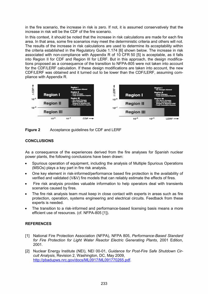
in the fire scenario, the increase in risk is zero. If not, it is assumed conservatively that the increase in risk will be the CDF of the fire scenario. In this context, it should be noted that the increase in risk calculations are made for each fire area. In that area, some fire scenarios may meet the deterministic criteria and others will not. The results of the increase in risk calculations are used to determine its acceptability within the criteria established in the Regulatory Guide 1.174 [6] shown below. The increase in risk associated with non-compliance with Appendix R of 10 CFR 50 [5] is acceptable, as it falls into Region II for CDF and Region III for LERF. But in this approach, the design modifica-tions proposed as a consequence of the transition to NFPA-805 were not taken into account for the CDF/LERF calculation. If these design modifications are taken into account, the new CDF/LERF was obtained and it turned out to be lower than the CDF/LERF, assuming com-pliance with Appendix R.
Figure 2 Acceptance guidelines for CDF and LERF CONCLUSIONS As a consequence of the experiences derived from the fire analyses for Spanish nuclear power plants, the following conclusions have been drawn:
Spurious operation of equipment, including the analysis of Multiple Spurious Operations (MSOs) plays a key part in fire risk analysis.
One key element in risk-informed/performance based fire protection is the availability of verified and validated (V&V) fire models that can reliably estimate the effects of fires.
Fire risk analysis provides valuable information to help operators deal with transients scenarios caused by fires.
The fire risk analysis team must keep in close contact with experts in areas such as fire protection, operation, systems engineering and electrical circuits. Feedback from these experts is needed.
The transition to a risk-informed and performance-based licensing basis means a more efficient use of resources. (cf. NFPA-805 [1]).
REFERENCES
[1] National Fire Protection Association (NFPA), NFPA 805, Performance-Based Standard for Fire Protection for Light Water Reactor Electric Generating Plants, 2001 Edition, 2001.
[2] Nuclear Energy Institute (NEI), NEI 00-01, Guidance for Post-Fire Safe Shutdown Cir-cuit Analysis, Revision 2, Washington, DC, May 2009, http://pbadupws.nrc.gov/docs/ML0917/ML091770265.pdf.
233

[3] United States Nuclear Regulatory Commission (U.S. NRC), Office of Nuclear Regulato-ry Research (RES), and Electric Power Research Institute (EPRI), Nuclear Power Plant Fire Modeling Applications Guide (NPP FIRE MAG), Final Report, NUREG-1934 and EPRI 1023259, Washington, DC, and Palo Alto, CA, USA, November 2012, http://www.nrc.gov/reading-rm/doc-collections/nuregs/staff/sr1934/.
[4] United States Nuclear Regulatory Commission (U.S. NRC) Office of Nuclear Reactor Regulation, Fire Dynamics Tools (FDTs): Quantitative Fire Hazard Analysis, Methods for the U.S. Nuclear Regulatory Commission Fire Protection Inspection Program, NUREG-1805, Final Report, Washington, DC, USA, December 2004, http://www.nrc.gov/reading-rm/doc-collections/nuregs/staff/sr1805/.
[5] United States Nuclear Regulatory Commission (U.S. NRC), Appendix R to Part 50 —Fire Protection Program for Nuclear Power Facilities Operating Prior to January 1, 1979, Page Last Reviewed/Updated Thursday, July 10, 2014, http://www.nrc.gov/reading-rm/doc-collections/cfr/part050/part050-0048.html.
[6] United States Nuclear Regulatory Commission (U.S. NRC), Office of Nuclear Regulato-ry Research (RES), An Approach for Using Probabilistic Risk Assessment in Risk-Informed Decisions on Plant-Specific Changes to the Licensing Basis, Regulatory Guide 1.174, http://pbadupws.nrc.gov/docs/ML0037/ML003740133.pdf.
[7] Electric Power Research Institute (EPRI) and United States Nuclear Regulatory Com-mission Office of Nuclear Research (NRC-RES), Fire PRA Methodology for Nuclear Power Facilities, EPRI/NRC-RES, Final Report, EPRI 1011989, NUREG/CR-6850, Palo Alto, CA, and Rockville, MD, USA September 2005, http://www.nrc.gov/reading-rm/doc-collections/nuregs/contract/cr6850/.
[8] United States Nuclear Regulatory Commission (U.S. NRC), Generic Letter 81-12, “Fire Protection Rule (45 FR 76602, November 19, 1980)”, 1981, http://www.nrc.gov/reading-rm/doc-collections/gen-comm/gen-letters/1981/gl81012.html.
[9] United States Nuclear Regulatory Commission (U.S. NRC), Office of Nuclear Regulato-ry Research (RES), and Electric Power Research Institute (EPRI), Verification and Vali-dation of Selected Fire Models for Nuclear Power Plant Applications, Supplement 1, Draft for comment, NUREG-1824 and EPRI 1011999, Washington, DC, and Palo Alto, CA, USA, November 2014, http://www.nrc.gov/reading-rm/doc-collections/nuregs/staff/sr1824/s1/.
[10] FAQ 08-0054, Demonstrating Compliance with Chapter 4 of NFPA 805, 2010, http://kgrs.public.haifire.com/NFPA%20805/Frequently%20Asked%20Questions%20(FAQs)/FAQ%2008-54%20Establishing%20Compliance%20with%20NFPA%20805%20Chapter%204/FAQ%2008-0054%20FREs%208-19-10%20ML102370581.pdf.
234

Fire - the Human DimensionImproving fire safety in nuclear power plants by improving awareness of fire hazards and influencing behavioursGeraint Williams & Pauline WoodwardONR (Office for Nuclear Regulation), UK
What are we sharing with you?
• Key messages from the work we do with licensees – other than assessment of designs
• Some of the reasons or evidence why we have reached these insights…
235

Key messages:(1) some “givens”
• Given:– Fire is undesirable on nuclear plants… – Fire events often have a strong human
dimension– High performing licensees/ duty holders
recognise this and try to manage fire risks proactively
Key messages:(2) the meat in the sandwich
In order to improve fire safety management it helps if• There are clear lines of responsibility for fire safety• There are ways of measuring im provements in fire
safety management• Fire safety is recognised as a duty of all staff (and
contractors) and supported by awareness training in aspects of fire
• Degraded plant condition is more evident if efforts are made to improve local environment (lighting, cleanliness, etc.)
236
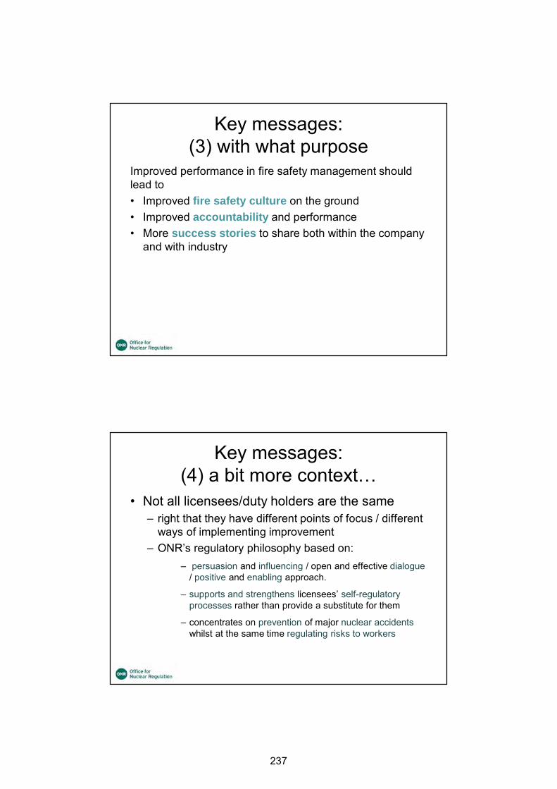
Key messages:(3) with what purpose
Improved performance in fire safety management should lead to• Improved fire safety culture on the ground• Improved accountability and performance • More success stories to share both within the company
and with industry
Key messages:(4) a bit more context…
• Not all licensees/duty holders are the same– right that they have different points of focus / different
ways of implementing improvement– ONR’s regulatory philosophy based on:
– persuasion and influencing / open and effective dialogue/ positive and enabling approach.
– supports and strengthens licensees’ self-regulatory processes rather than provide a substitute for them
– concentrates on prevention of major nuclear accidents whilst at the same time regulating risks to workers
237
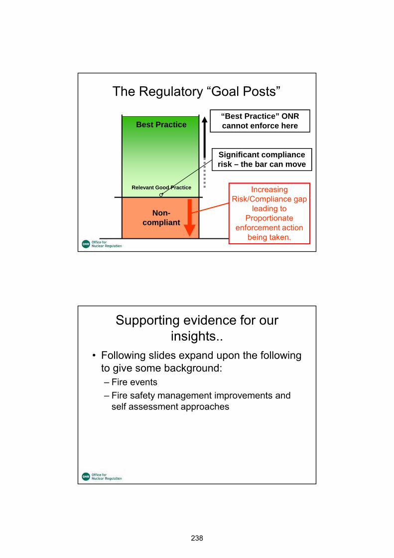
Legal Requirement(SFAIRP)
Best Practice
Non-compliant
The Regulatory “Goal Posts”
“Best Practice” ONR cannot enforce here
Relevant Good Practice
Significant compliance risk – the bar can move
Increasing Risk/Compliance gap
leading to Proportionate
enforcement action being taken.
Supporting evidence for our insights..
• Following slides expand upon the following to give some background:– Fire events– Fire safety management improvements and
self assessment approaches
238
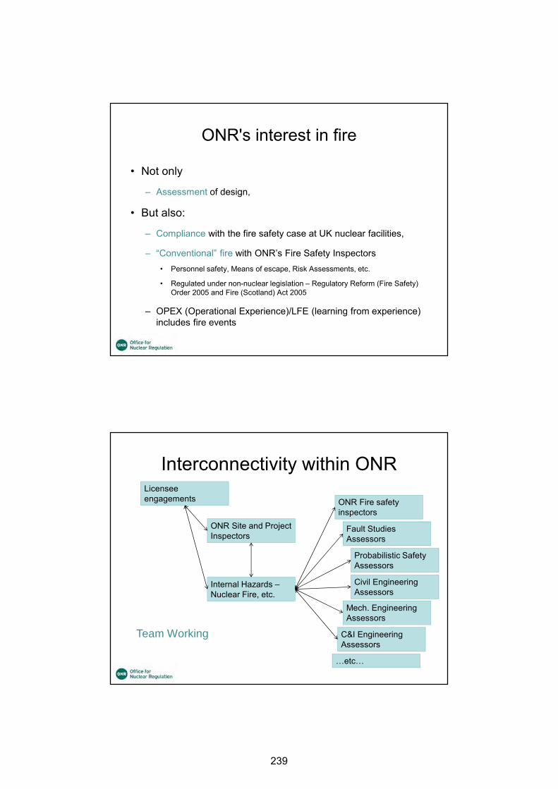
ONR's interest in fire
• Not only
– Assessment of design,
• But also:
– Compliance with the fire safety case at UK nuclear facilities,
– “Conventional” fire with ONR’s Fire Safety Inspectors• Personnel safety, Means of escape, Risk Assessments, etc.
• Regulated under non-nuclear legislation – Regulatory Reform (Fire Safety) Order 2005 and Fire (Scotland) Act 2005
– OPEX (Operational Experience)/LFE (learning from experience) includes fire events
Interconnectivity within ONR
Internal Hazards –Nuclear Fire, etc.
ONR Fire safety inspectors
ONR Site and Project Inspectors
Fault Studies Assessors
Probabilistic Safety Assessors
Civil Engineering Assessors
Mech. Engineering Assessors
C&I Engineering Assessors
…etc…
Licensee engagements
Team Working
239
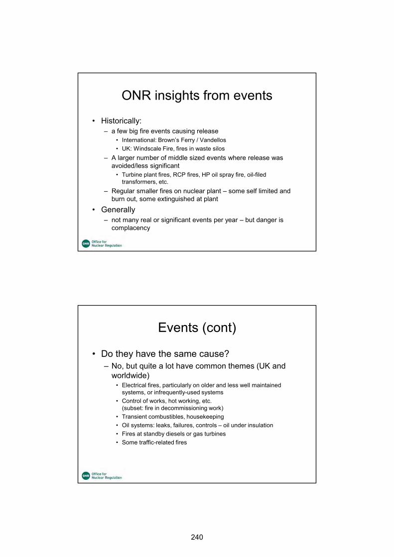
ONR insights from events
• Historically:– a few big fire events causing release
• International: Brown’s Ferry / Vandellos• UK: Windscale Fire, fires in waste silos
– A larger number of middle sized events where release was avoided/less significant
• Turbine plant fires, RCP fires, HP oil spray fire, oil-filed transformers, etc.
– Regular smaller fires on nuclear plant – some self limited and burn out, some extinguished at plant
• Generally – not many real or significant events per year – but danger is
complacency
Events (cont)
• Do they have the same cause?– No, but quite a lot have common themes (UK and
worldwide)• Electrical fires, particularly on older and less well maintained
systems, or infrequently-used systems• Control of works, hot working, etc.
(subset: fire in decommissioning work)• Transient combustibles, housekeeping• Oil systems: leaks, failures, controls – oil under insulation• Fires at standby diesels or gas turbines• Some traffic-related fires
240

Success stories…
• Some recent examples– Licensee improvement initiative for construction
projects• Included: responsibilities, increased monitoring and audits,
improved procedures and company standards, improved awareness of fire hazards, shared learning briefs, oversight, etc.
– Licensee developed and delivered at all their sites an improved fire safety awareness course, delivered to all relevant staff, including contractor support staff
Success stories (cont.)…
• (more examples)…– Licensee focus on improving fire safety management at all levels
of the company• Many aspects including: development of a fleet fire safety index to
measure aspects of fire safety, fire “referential” inspections – a high level audit, comparison with French practice, improvements in plant condition, etc.
• Has made definite improvements in “look and feel” of plant and fire events have reduced (causal or coincidence?: beware complacency!)
• UK good practice is shared at a cross-licensee forum –allows learning from others– Not all licensees have same problems, but all can learn from
other
241
Measuring fire safety management performance?
• Why measure?– Good way of communicating with higher management and
stakeholders, and to get buy-in for improvement plans
• How to measure? No clear approach:– INPO Performance Objectives, Criteria and Guidance– WANO Peer reviews– IAEA NS-G-2.1 (also Safety Series No.50-P-9, marked as
obsolete)– Various company-developed approaches
(e.g. EDF NGL developed a “fire referential” based upon all the references above)
– Some potential for developing an industry wide “Capability Management Model”
242

23rdInternational Conference on Structural Mechanics in Reactor Technology (SMiRT 23) - 14h
International Post-Conference Seminar on “FIRE SAFETY IN NUCLEAR POWER PLANTS AND INSTALLATIONS“
DEFENCE-IN-DEPTH STRATEGY OF FIRE PROTECTION AND ITS RELEVANCE AFTER FINAL SHU TDOWN
(BY THE EXAMPLE OF GERMANY)
Michael Beesen, Benjamin Ernst, Günter Fischer
TÜV SÜD Industrie Service GmbH, Germany ABSTRACT Nuclear power plants (NPP) are protected against internal and external fires by a fire protection defence-in-depth concept including the following precautionary measures: operational, structural and equipment related fire protection measures as well as manual fire fighting. The fire protection measures are designed in consideration of fires to be expected (from fire loads permanently and temporarily present together with potential ignition sources) in order to prevent a violation of both the protection goals of public law and the nuclear protection goals / radiological safety objectives in case of internal and external fires. The aspect “What is the future significance of the fire protection defence-in-depth concept?” needs to be considered with regard to the situation following the final shutdown. From our point of view as a TSO (technical safety organization) both the non-nuclear protection goals (e.g. prevent occurrence of a fire; ensure escape and rescue of humans) as well as the nuclear ones have to be ensured after final shutdown of a nuclear plant. The protection goals of public law will almost completely remain after the plant has stopped commercial operation while the nuclear safety objectives will be stepwise reduced in consideration of the decommissioning status until the end of the nuclear supervision. Nevertheless, the fire protection concept must clearly specify those fire protection measures that are necessary to ensure the plants’ safety. The situation on site regularly needs to be under examination to check if the fire protection concept covers all conditions to be considered and if the existing fire protection measures are sufficient or if an adaption is necessary. INTRODUCTION German Nuclear Phase-out In 2010, the German Parliament agreed a lifetime extension for German NPP. As a result of the Fukushima Dai-ichi reactor accidents the German Parliament decided in 2011 that sev-eral energy suppliers had to stop commercial operation of their NPP. The German Atomic Energy Act [1] was changed by August 2011. Following this, the energy suppliers had finally to stop production of energy at eight NPP units. The change of the German Atomic Energy Act [1] also includes the decision to stop the production of nuclear energy in all NPP latest by the end of the year 2022 (German nuclear phase-out). Following 2011, the remaining op-erating NPP will have to stop one after the other commercial operation. Most recently, the Grafenrheinfeld NPP stopped operation in June 2015. Figure 1 shows the German NPP used for commercial production of energy, their status, and the latest date of final (safe) shutdown.
243
Figure 1 German NPP - status and latest date of shutdown Concerning those NPP with shutdowns since 2011, the energy suppliers prefer immediate dismantling for decommissioning of their NPP. In addition to the support of the remaining operating German NPP and nuclear projects outside Germany, German nuclear industry will have to handle the disused NPP in the next years and decades to achieve nuclear dismantling goals (nuclear fuel no longer present on site, radioactive materials no longer present, end of nuclear supervision). The required time for phase-out operation ("post-commercial safe shutdown”), decommissioning and dismantling is estimated to be 10 to 15 years per plant unit following the proclaimed authorities’ permission (license) for decommissioning. Legal Requirements and Protection Goals Concerning constructing, using, modifying and dismantling of industrial buildings in Germany different legal requirements have to be taken into account, particularly the non-nuclear building law, the occupational health and safety law and the nuclear safety law. Relating to public safety and order attention should be paid to the building law with its buildings codes, technical building regulations and technical rules, etc. Occupational health and safety is achieved by complying particularly with the German labour protection act, technical rules for workplaces as well as with standards and guidelines of the employers´ mutual insurance
244

association. Nuclear safety is ensured if claims according to the state-of-the-art of science and technology are met. Therefore, attention should be paid especially to the Atomic Energy Act [1], the Radiation Protection Ordinance ], the Safety Requirements for NPP [3], the RSK1 Guidelines, the ESK2 and SSK3 Recommendations as well as the KTA safety standards (e. g. KTA4 standards series 2101 “Fire Protection in Nuclear Power Plants” [4]). The relevant legal requirements are summarized briefly in Figure 2.
Figure 2 Legal German requirements The major aim of the German building codes is to ensure that public safety and order, in particular life, health and the basis of life, are not endangered. Concerning fire safety this aim is put in concrete terms by the fire protection goals “prevention of fire occurrence”, “prevention of fire and smoke spread”, “enabling rescue of people” and “enabling effective fire fighting” (cf. Figure 3).
Figure 3 General and fire related protection goals of building law 1 RSK: Reactor Safety Commission (in German: Reaktor-Sicherheitskommission) 2 ESK: Nuclear Waste Management Commission (German for: Entsorgungskommission) 3 SSK: Commission on Radiological Protection (German for: Strahlenschutzkommission) 4 KTA: Nuclear Safety Standards Commission (German for: Kerntechnischer Ausschuss)
245

According to the German Atomic Energy Act [1] it is necessary that precautions have been taken in light of the state-of-the-art with respect to science and technology for preventing damages resulting from the construction, operation and dismantling of NPP to ensure nu-clear safety. This aim is put into concrete terms with the “Safety Requirements for Nuclear Power Plants” [3] by the nuclear protection goals “control of reactivity”, “cooling of fuel as-semblies” and “confinement of radioactive materials” as well as by the radiological safety ob-jectives “limitation of radiation exposure”. To ensure the nuclear protection goals and the ra-diological safety objectives in case of on-site building-internal and building-external fires, it is required to have a defence-in-depth fire protection concept including fire protection measures that suitably protect relevant structures, systems and components as well as plant personnel (cf. Figure 4).
Figure 4 General and fire related nuclear protection goals Figure 5 shows during which operating phases, e.g. normal operation, shutdown states such as outages for refuelling, inspection and maintenance, safe shutdown for starting removing components, and dismantling NPP, the building law’s protection goals and the nuclear pro-tection goals respectively the radiological safety objectives are relevant and have to be con-sidered.
Figure 5 Building law’s protection goals and nuclear protection goals / radiological
safety objectives and their significance subject to plat operational states
246
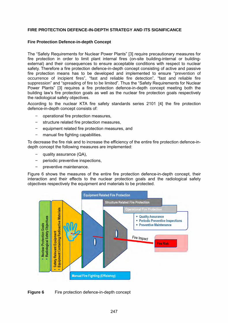
FIRE PROTECTION DEFENCE-IN-DEPTH STRATEGY AND ITS SIGNIFICANCE Fire Protection Defence-in-depth Concept The “Safety Requirements for Nuclear Power Plants” [3] require precautionary measures for fire protection in order to limit plant internal fires (on-site building-internal or building-external) and their consequences to ensure acceptable conditions with respect to nuclear safety. Therefore a fire protection defence-in-depth concept consisting of active and passive fire protection means has to be developed and implemented to ensure “prevention of occurrence of incipient fires”, “fast and reliable fire detection”, “fast and reliable fire suppression” and “spreading of fire to be limited”. Thus the “Safety Requirements for Nuclear Power Plants” [3] requires a fire protection defence-in-depth concept meeting both the building law’s fire protection goals as well as the nuclear fire protection goals respectively the radiological safety objectives. According to the nuclear KTA fire safety standards series 2101 [4] the fire protection defence-in-depth concept consists of:
− operational fire protection measures, − structure related fire protection measures, − equipment related fire protection measures, and − manual fire fighting capabilities.
To decrease the fire risk and to increase the efficiency of the entire fire protection defence-in-depth concept the following measures are implemented:
− quality assurance (QA), − periodic preventive inspections, − preventive maintenance.
Figure 6 shows the measures of the entire fire protection defence-in-depth concept, their interaction and their effects to the nuclear protection goals and the radiological safety objectives respectively the equipment and materials to be protected.
Figure 6 Fire protection defence-in-depth concept
247
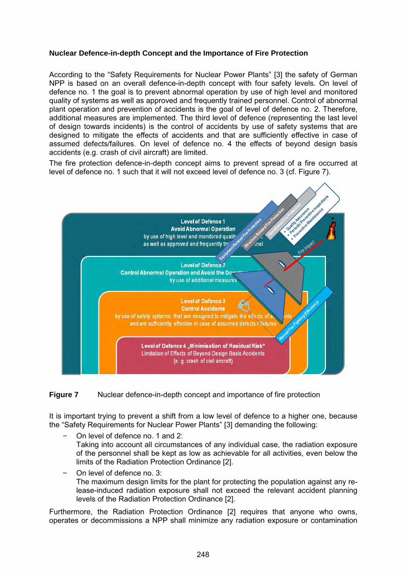
Nuclear Defence- in-depth Concept and the Importance of Fire Protection According to the “Safety Requirements for Nuclear Power Plants” [3] the safety of German NPP is based on an overall defence-in-depth concept with four safety levels. On level of defence no. 1 the goal is to prevent abnormal operation by use of high level and monitored quality of systems as well as approved and frequently trained personnel. Control of abnormal plant operation and prevention of accidents is the goal of level of defence no. 2. Therefore, additional measures are implemented. The third level of defence (representing the last level of design towards incidents) is the control of accidents by use of safety systems that are designed to mitigate the effects of accidents and that are sufficiently effective in case of assumed defects/failures. On level of defence no. 4 the effects of beyond design basis accidents (e.g. crash of civil aircraft) are limited. The fire protection defence-in-depth concept aims to prevent spread of a fire occurred at level of defence no. 1 such that it will not exceed level of defence no. 3 (cf. Figure 7).
Figure 7 Nuclear defence-in-depth concept and importance of fire protection It is important trying to prevent a shift from a low level of defence to a higher one, because the “Safety Requirements for Nuclear Power Plants” [3] demanding the following:
− On level of defence no. 1 and 2: Taking into account all circumstances of any individual case, the radiation exposure of the personnel shall be kept as low as achievable for all activities, even below the limits of the Radiation Protection Ordinance [2].
− On level of defence no. 3: The maximum design limits for the plant for protecting the population against any re-lease-induced radiation exposure shall not exceed the relevant accident planning levels of the Radiation Protection Ordinance [2].
Furthermore, the Radiation Protection Ordinance [2] requires that anyone who owns, operates or decommissions a NPP shall minimize any radiation exposure or contamination
248
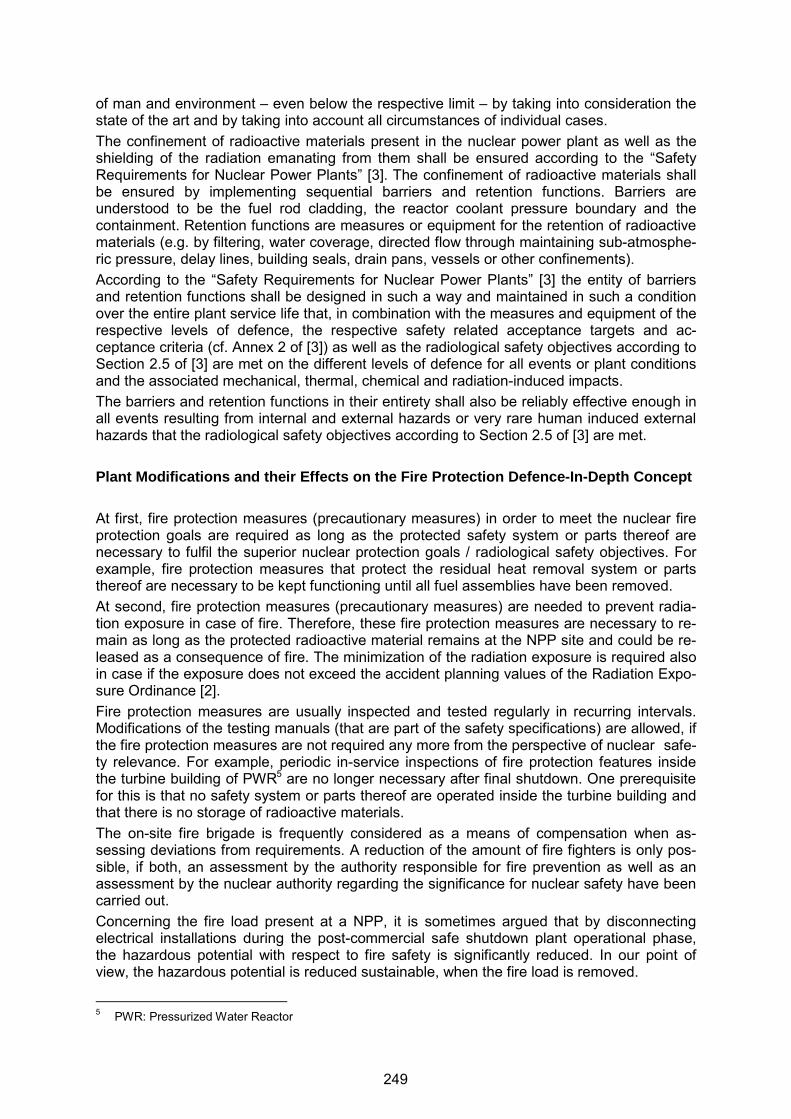
of man and environment – even below the respective limit – by taking into consideration the state of the art and by taking into account all circumstances of individual cases. The confinement of radioactive materials present in the nuclear power plant as well as the shielding of the radiation emanating from them shall be ensured according to the “Safety Requirements for Nuclear Power Plants” [3]. The confinement of radioactive materials shall be ensured by implementing sequential barriers and retention functions. Barriers are understood to be the fuel rod cladding, the reactor coolant pressure boundary and the containment. Retention functions are measures or equipment for the retention of radioactive materials (e.g. by filtering, water coverage, directed flow through maintaining sub-atmosphe-ric pressure, delay lines, building seals, drain pans, vessels or other confinements). According to the “Safety Requirements for Nuclear Power Plants” [3] the entity of barriers and retention functions shall be designed in such a way and maintained in such a condition over the entire plant service life that, in combination with the measures and equipment of the respective levels of defence, the respective safety related acceptance targets and ac-ceptance criteria (cf. Annex 2 of [3]) as well as the radiological safety objectives according to Section 2.5 of [3] are met on the different levels of defence for all events or plant conditions and the associated mechanical, thermal, chemical and radiation-induced impacts. The barriers and retention functions in their entirety shall also be reliably effective enough in all events resulting from internal and external hazards or very rare human induced external hazards that the radiological safety objectives according to Section 2.5 of [3] are met. Plant Modifications and their Effects on the Fire Protection Defence-In-Depth Concept At first, fire protection measures (precautionary measures) in order to meet the nuclear fire protection goals are required as long as the protected safety system or parts thereof are necessary to fulfil the superior nuclear protection goals / radiological safety objectives. For example, fire protection measures that protect the residual heat removal system or parts thereof are necessary to be kept functioning until all fuel assemblies have been removed. At second, fire protection measures (precautionary measures) are needed to prevent radia-tion exposure in case of fire. Therefore, these fire protection measures are necessary to re-main as long as the protected radioactive material remains at the NPP site and could be re-leased as a consequence of fire. The minimization of the radiation exposure is required also in case if the exposure does not exceed the accident planning values of the Radiation Expo-sure Ordinance [2]. Fire protection measures are usually inspected and tested regularly in recurring intervals. Modifications of the testing manuals (that are part of the safety specifications) are allowed, if the fire protection measures are not required any more from the perspective of nuclear safe-ty relevance. For example, periodic in-service inspections of fire protection features inside the turbine building of PWR5 are no longer necessary after final shutdown. One prerequisite for this is that no safety system or parts thereof are operated inside the turbine building and that there is no storage of radioactive materials. The on-site fire brigade is frequently considered as a means of compensation when as-sessing deviations from requirements. A reduction of the amount of fire fighters is only pos-sible, if both, an assessment by the authority responsible for fire prevention as well as an assessment by the nuclear authority regarding the significance for nuclear safety have been carried out. Concerning the fire load present at a NPP, it is sometimes argued that by disconnecting electrical installations during the post-commercial safe shutdown plant operational phase, the hazardous potential with respect to fire safety is significantly reduced. In our point of view, the hazardous potential is reduced sustainable, when the fire load is removed.
5 PWR: Pressurized Water Reactor
249

After final shutdown, a modification of prevailing conditions concerning the utilization may occur. For example, performing a decontamination of the reactor coolant system may result in additional fire loads and cable or pipework routing along access and escape routes when the number of personnel is significantly increased. With regard to fire safety this is accepta-ble if this situation is covered by measures of the fire protection defence-in-depth concept being already in place or if deviations from regulatory requirements are compensated by ad-ditional fire protection measures (e.g. installation of additional fire detectors; immediate alert of the on-site fire brigade in case of a fire detector being actuated instead of alert after verifi-cation by shift personnel; installation of self-rescuers / smoke hoods, etc.). Further examples for an assessment being required with regard to adequacy, suitability and efficiency of the fire protection defence-in-depth concept including the respective measures being in place are the installation of additional work stations for waste treatment or the installation of addi-tional laboratory work stations. CONCLUSIONS As part of a fire protection defence-in-depth concept, fire protection measures as precautionary measures against fire hazards are required to prevent that functions of items important to safety are inadmissibly impaired. The nuclear protection goals and radiological safety objectives always have to be taken into account and therefore the fire protection goals have to be ensured. The limitation of the effects of a plant internal fire to the valid accident planning values according to the Radiation Protection Ordinance [2] is not sufficient. According to [2] the radiation exposure always has to be minimized to a level below the permissible limits of the Radiation Protection Ordinance [2]. Plant modifications require a regular verification of the existing fire protection defence-in-depth concept with its fire protection measures regarding their suitability and efficiency. REFERENCES [1] Federal Ministry of Justice and Consumer Protection, Act on the Peaceful Utilisation of
Atomic Energy and the Protection against its Hazards, December, 23, 1959, as amend-ed and promulgated on July, 15, 1985, last amendment of July 15, 2015, Federal Bulle-tin I, p. 1324, http://www.gesetze-im-internet.de/atg/BJNR008140959.html (in German), http://www.bfs.de/SharedDocs/Downloads/BfS/DE/rsh/a1-englisch/A1-08-13-AtG.pdf (former version in English).
[2] Federal Ministry of Justice and Consumer Protection, Ordinance on the Protection against Damage and Injuries Caused by Ionizing Radiation (Radiation Protection Ordi-nance) as amended and published on July 20, 2001 and last revised on December 11, 2014, http://www.bfs.de/SharedDocs/Downloads/BfS/DE/rsh/a1-englisch/A1-12-14.pdf.
[3] Federal Ministry for the Environment, Nature Conservation, Building and Nuclear Safe-ty, Safety Requirements for Nuclear Power Plants as amended and published on No-vember 22, 2012 and revised version of March 3, 2015, http://www.bfs.de/SharedDocs/Downloads/BfS/EN/hns/a1-english/A1-03-15-SiAnf.pdf.
[4] Nuclear Safety Standards Commission (KTA, German for Kerntechnischer Ausschuss), KTA-Standard series 2101 “Fire Protection in Nuclear Power Plants”, Safety Standards of the Nuclear Safety Standards Commission (KTA), December 2000, (actually being revised) http://www.kta-gs.de/e/standards/2100/2101_1_engl_2000_12.pdf, http://www.kta-gs.de/e/standards/2100/2101_2_engl_2000_12.pdf, http://www.kta-gs.de/e/standards/2100/2101_3_engl_2000_12.pdf.
250

23rd International Conference on Structural Mechanics in Reactor Technology (SMiRT 23) - 14th
International Post-Conference Seminar on “FIRE SAFETY IN NUCLEAR POWER PLANTS AND INSTALLATIONS“
FEEDBACK FROM RECENT OPERATING EXPERIENCE IN NUCLEAR POWER PLANTS REGARDING FIRE SAFETY
Burkhard Forell
Gesellschaft für Anlagen- und Reaktorsicherheit (GRS) gGmbH, Cologne, Germany
ABSTRACT The paper provides insights from the operating experience in German nuclear power plants with reportable fire safety related events. The three reportable events outlined in more detail resulted in German Information Notices prepared by GRS and distributed on behalf of the Federal German regulatory body. The events concerned deficiencies at pipe penetration seals, which were not filled with mineral wool. Also at fire doors deficiencies of the insulation inside the door wings occurred. One event concerned a smouldering fire of rubber material in a waste drum which was placed in a plant internal drying facility for radioactive waste. INTRODUCTION Two reportable events have occurred recently in German Nuclear Power Plants (NPP) affecting fire protection means. These events had some generic aspects in common. In the first event, in penetration seals of pipes leading through fire barriers the filling with mineral wool was missing. Pipes with larger diameters additionally need a thermal insulation of the pipe itself, which was also missing for some pipe penetration seals. In the second event, deficiencies at fire doors constructed according to former standards were found, which also concerned the thermal insulation. A third reportable event being important to nuclear fire safety is a smouldering fire of rubber material within the plant internal drying facility for radioactive waste drums. These recently reported events related to fire safety have been analysed in more detail. FINDINGS AT PENETRATION SEALS OF NON-COMBUSTIBLE PIPES The pipe penetration seals in walls or ceilings with requirements to fire protection have to be constructed according to the non-nuclear building code with the associated guidelines for pipework and cable installations [1]. These require that starting with a certain diameter not only the ring gap between pipe and wall/ceiling has to be filled with non-combustible mineral material, but also the pipe itself has to be insulated in a way that the temperature on the cold side of the pipe and the seal does not exceed 180 K in case of a standard test fire according to the ISO 834 [2] standard fire curve for a defined time. For different situations the detailed pipe penetration seal design is typically described in a so-called “pipe penetration seal catalogue” of the given NPP. According to the catalogue, a typical design of a pipe penetration seal of a non-combustible pipe consists of a filling of the ring gap between the pipe and the jacket tube which is fixed to the wall/ceiling. The filling is made by mineral wool with a melting point exceeding T > 1000 °C. Both ends of the jacket tube are typically sealed with a silicone sealing or with a reversible silicone expansion joint (cf. Figure 1). Empty seals consisting of the jacket tube only are filled with mineral wool and covered with a sheet metal cap on both sides (see Figure 1, bottom-middle and top-right).
251

Figure 1 Pipe penetration seals of non-combustible pipes sealed by reversible silicone expansion joints and one reserve pipe seal closed with a sheet metal cap (bottom-middle and top-right); image source: G+H Isolierung GmbH, www.guh-brandschutz.de
For non-combustible pipes with diameters larger than DN 160 to 200 (depending on the spe-cific requirement), an insulation of mineral wool with a melting point T > 1000 °C additional to the one of the ring gap of the pipe itself is needed (cf. Figure 2).
Figure 2 Schematic pipe penetration seal for non-combustible pipes with diameters
over DN 160 to 200 (depending on the specific requirement) with insulation of the ring gap and additional insulation of the pipe; image source: G+H Isolier-ung GmbH
252
One German NPP has recently reported a finding that at a number of pipe penetration seals the seals were closed with the silicone expansion joints or the sheet metal cap, but the inner filling of the ring gap with mineral wool was missing. Therefore, the pipe penetration seal could only be considered as being smoke-tight but not tight against enduring heat by hot gases or flames. Moreover, the insulations of the pipe were missing at in total 29 pipe pene-tration seals with diameters larger than 200 mm. The deficiencies obviously resulted already from the construction phase of the plant in the 1980ies, when the pipe penetration seals had been closed from both sides without filling in the mineral wool. Regular in-service inspections on pipes have been performed; however these inspections only consisted of a visual inspection without opening the seals. The relevance for nuclear safety can be considered as minor. This is first because the pipe seals still ensure a certain structural fire protection at least for natural fires according to the German operation experience, which are less severe than the ISO 834 standard test fire. Furthermore, the structural fire protection means are only one layer of protection in the plant fire protection concept. By means of a German Information Notice [3] prepared by GRS on behalf of the Federal German nuclear regulatory body BMUB the German nuclear power plant operators were in-formed about the event including the following suggestions for preventing recurrence: In addition to the regular in-service inspections on pipe seals, random tests shall be per-
formed where a number of pipe seals are opened and the filling of the ring gap by min-eral wool is checked. In case of any findings the size of the sample has to be extended.
All pipe penetration seals shall be checked for the diameter that will require the seals to be equipped with an additional pipe insulation to meet the 180 K temperature criterion.
Pipe penetration seals should be clearly indicated by a number and a sign showing that the seal meets the fire safety requirements. The documentation to be provided and kept up to date should include number, location, and type of the pipe penetration seal as well as any opening and closing having been performed.
FINDINGS AT FIRE DOORS MANUFACTURED ACCORDING TO FORMER CONSTRUCTION STANDARDS Findings at fire doors manufactured according to former construction standards were report-ed from two German NPPs. After some old fire doors had been replaced by new ones and cut open after use, a considerable number of these fire doors showed problems with the in-sulation inside the door wing. In some cases, the mineral wool insulation had shrunk causing a gap of approximately 30 mm at the upper part of the door. The fire doors had been in ser-vice for more than 35 years. For comparison, Figure 3 gives an example of a door wing where the mineral wool filling is complete. Other doors that were checked in the two plants also showed missing parts of thermal insulation close to the lock casing. Concerning the shrinking it is assumed that the deficiencies result from aging effects. The missing parts of the insulation were attributed to a lack of quality insurance during the manufacturing of the fire doors in the beginning of the 1970ies. The findings described were observed at fire doors which were produced by at least three different manufactures. Similar to the reported event on pipe penetration seals, the relevance with respect to nuclear safety of these events on fire doors can be considered as minor. This is particularly due to the fact that according to the operation experience in Germany the fire doors still provide a considerable level of structural fire protection for natural fires. In the beginning of the 1970ies, most fire doors in Germany were manufactured according to the German standards DIN 18081, DIN 18082, and DIN 18084 consisting of construction plans of major parts of the doors, including the door wing insulation by mineral wool that was fixed by wire. These standards from 1969 were withdrawn at the end of 1976, because stronger test criteria were enacted before. Only the standard DIN 18082 [4] on 30 min rated
253
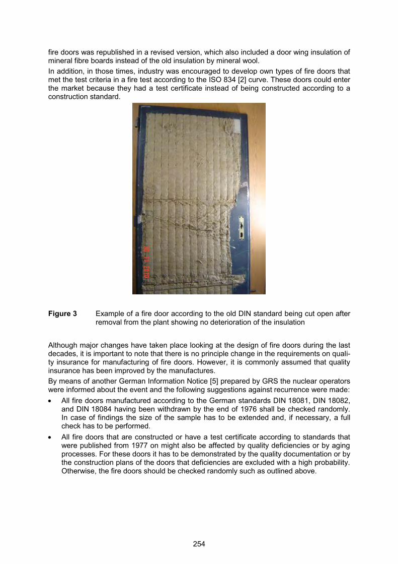
fire doors was republished in a revised version, which also included a door wing insulation of mineral fibre boards instead of the old insulation by mineral wool. In addition, in those times, industry was encouraged to develop own types of fire doors that met the test criteria in a fire test according to the ISO 834 [2] curve. These doors could enter the market because they had a test certificate instead of being constructed according to a construction standard.
Figure 3 Example of a fire door according to the old DIN standard being cut open after removal from the plant showing no deterioration of the insulation
Although major changes have taken place looking at the design of fire doors during the last decades, it is important to note that there is no principle change in the requirements on quali-ty insurance for manufacturing of fire doors. However, it is commonly assumed that quality insurance has been improved by the manufactures. By means of another German Information Notice [5] prepared by GRS the nuclear operators were informed about the event and the following suggestions against recurrence were made: All fire doors manufactured according to the German standards DIN 18081, DIN 18082,
and DIN 18084 having been withdrawn by the end of 1976 shall be checked randomly. In case of findings the size of the sample has to be extended and, if necessary, a full check has to be performed.
All fire doors that are constructed or have a test certificate according to standards that were published from 1977 on might also be affected by quality deficiencies or by aging processes. For these doors it has to be demonstrated by the quality documentation or by the construction plans of the doors that deficiencies are excluded with a high probability. Otherwise, the fire doors should be checked randomly such as outlined above.
254

SMOULDERING FIRE OF WASTE MATERIAL WITHIN THE DRYING FACILITY A smouldering fire within a waste drum that was put into a plant internal drying facility was reported by one German NPP. However, latterly GRS was made aware of similar, but non-reportable events that did not fulfil the reporting criteria. The 200 l waste drum was filled with mainly with hard rubber. The material was originally used as a coating of a vessel and therefore was crushed, which decreased the self-ignition temperature (SIT) of the material. The material consisted of natural rubber, hard-rubber powder and sulphur. The drum was put into the facility for drying. The drying process is performed by air that cir-culates in the facility. The air is heated up by electric heaters to a temperature of about 155 °C. Then it is led to the drying chamber to heat-up of the waste drum and to take up the water vapour. Finally, the air is cooled down to collect the condensate before it is heated up again. The drying process is finished as soon as the mass flow of condensate is below a cer-tain limit. During the drying process the regular closure of the waste drum is opened and the drum is covered with a steam screen (a metal plate with holes) that allows evaporation of water. After the drying process ended as normal the heating switched off and the steam screen was automatically lifted up to increase cooling of the drum. The air in the chamber of the drum cooled down to almost room temperature. After that the air temperature measured in the chamber increased slowly but continuously. Thus a temperature surveillance alarm was au-tomatically triggered. The surveillance alarm of the system was not indicated as fire alarm and was first ignored in the main control room. It was recognized after shift changeover in the morning. After exami-nation of the situation, plant personnel triggered the manual CO2-inerting of the drying chamber. As the CO2-system was not able to extinguish the smouldering fire in the waste drum, the drying facility was opened by the plant fire brigade and the waste material was fi-nally extinguished with water and foam as extinguishing agents. The smouldering fire did not cause any radioactive releases that could be measured outside the drying facility. There was no contamination or harm of personnel. The fire severity did not exhibit any impact on nuclear safety. Probably, fires on radioactive waste drums may lead to contamination. A smouldering fire may cause an open fire or may produce smouldering gas-es leading to ignitable atmospheres within a drying facility. Explosions or backdraft-like phe-nomena may not be excluded. The investigations after the smouldering fire showed that the SIT of the rubber material was significantly lowered by crushing it. The SIT was assumed to be in the order of 300 °C, but was value was valid for the material when it was applied according to the design as coating of vessels. With crushing the material, the SIT decreased and was in later laboratory exper-iments reproduced at 160 °C. The SIT is a safety related parameter depending on the boundary conditions. The SIT e.g. decreases if the size of the sample increases, because the ratio of sample volume divided by the sample surface increases. The SIT also increases with decreasing oxygen concentra-tion within the sample, however even at oxygen concentrations of about 2 % self-ignition in granules, etc. does occur [6], [7]. In an German Information Notice [8] prepared by GRS on behalf of the Federal German reg-ulatory body, BMUB, GRS informed the German NPP operators about the event, including the following proposals for preventing recurrence: Bevor using the drying facilities with new materials where the ignition properties are un-
known, self-ignition processes shall be ruled out. This can be done by test dryings, where scaling effects concerning the influence of the sample size on the self-ignition temperature should be considered.
255
It shall be checked if the time between the end of the drying process and lifting up of the steam screen can be increased to limit the oxygen access into the waste drum. (This measure is assumed by GRS to reduce the risk of open flames in case of fire. The risk of ignition may also be reduced by the steam screen, however it is not known if and in how far the oxygen concentration within the waste drum is reduced by the steam screen.)
Fire detection within the drying facility shall be improved (CO measurements are the first choice in fire detection; however difficulties were reported for CO measurements be-cause of the high vapour content in the system. Temperature measurements within the waste drums were also recommended.) The indication of the signals on the main control room should be improved.
During operation and cooling phases of the drying facility it shall be surveyed regularly by plant walk down.
Since the installed CO2 inert gas fire suppression system is not suitable to extinguish a smouldering fire within a drum, it should be considered if more reliable extinguishing equipment could be installed at the drying facility.
CONCLUSIONS German nuclear operators reported several events with respect to fire safety during the last years. Three of these events showed generic aspects and therefore resulted into German In-formation Notices which where prepared by GRS. Concerning the findings at pipe penetra-tion seals, the first feedback from German operators shows that there were no further sys-tematic deficiencies at any other German NPP. Since the two other information notices are quite new, the feedback of the operators is still ongoing. REFERENCES [1] ARGEBAU, Muster-Richtlinie über brandschutztechnische Anforderungen an Leitungs-
anlagen (Muster-Leitungsanlagen-Richtlinie MLAR), Stand: 17.11.2005 (in German), http://www.bauordnungen.de/MLAR.pdf.
[2] International Organization of Standardization (ISO) (Ed.), ISO 834-1: Fire-resistance tests - Elements of building construction - Part 1: General requirements, Geneva, Swit-zerland, 1999, http://www.iso.org/iso/home/store/catalogue_tc/catalogue_detail.htm?csnumber=2576.
[3] Gesellschaft für Anlagen- und Reaktorsicherheit (GRS) GmbH, Weiterleitungsnachricht (German acronym for Information Notice) zu meldepflichtigen Ereignissen in Kernkraft-werken der Bundesrepublik Deutschland (WLN 2013/02) „Befunde an bautechnischen Brandschutzmaßnahmen im Kernkraftwerk XXX am XX.YY.2012 sowie gend“ (title anonymized), Cologne, Germany, February 2013 (in German).
[4] Deutsches Institut für Normung (DIN) (Ed.), DIN 18082, Feuerschutzabschlüsse; Stahl-türen T 30-1, Bauart für Größenbereich A (German for: Fire barriers; steel doors T 30-1; construction type for size range A (in German), December 1976.
[5] Gesellschaft für Anlagen- und Reaktorsicherheit (GRS) gGmbH, Weiterleitungsnach-richt (German acronym for Information Notice) zu meldepflichtigen Ereignissen in Kern-kraftwerken der Bundesrepublik Deutschland (WLN 2013/02a) Ergänzung zur Weiterlei-tungsnachricht WLN 2013/02 „Befunde an Rohrabschottungen in einem weiteren Kern-kraftwerk sowie an Brandschutztüren älterer Bauart in zwei Kernkraftwerken“, Cologne, Germany, May 2015 (in German).
[6] Krause, U., Fires in Silos - Hazards, Prevention, and Fire Fighting, Wiley-VCH, Wein-heim, Germany, 2009.
256

[7] Schmidt, M. et al., “Selbstentzündung von Stäuben und Schüttgütern bei vermindertem Sauerstoffgehalt”, Chemie Ingenieur Technik (74), pp. 1735-1737, 2002.
[8] Gesellschaft für Anlagen- und Reaktorsicherheit (GRS) gGmbH, Weiterleitungsnach-richt (German acronym for Information Notice) zu meldepflichtigen Ereignissen in Kern-kraftwerken der Bundesrepublik Deutschland (WLN 2015/02) „Schwelbrand von Rest-stoffen in einem Abfallgebinde innerhalb der Trocknungsanlage im Kernkraftwerk XX, am XX.YY.2011“ (title anonymized), Cologne, Germany, April 2015, (in German).
257
4 Seminar Conclusions and Outlook
The 14th International Seminar on ‘Fire Safety in Nuclear Power Plants and Installa-
tions’ demonstrated ongoing progress in nuclear fire safety with respect to performed
experiments and assessment. However, there are still challenges since the knowledge
on several fire related phenomena is still not yet mature and the analytical tools applied
need further enhancement.
The presentations at this seminar provided an added value to the state-of-the-art in nu-
clear fire protection highlighting recent developments, but also describing in an open
manner still unsolved issues in this field.
The following conclusions have been drawn from the seminar:
Although progress has been achieved with respect to fire safety in nuclear installations
and its assessment, fire safety is still an important issue which has to be addressed in
all types of nuclear facilities from their construction throughout their operational and
post-operational lifetime until decommissioning has been completed. Currently, as the
seminar has indicated, the main focus is on the planning, construction and operational
phase.
With respect to research activities focusing on real case fire scenarios in nuclear instal-
lations it has to be stated that the actually ongoing experimental nuclear fire research
programs provide valuable insights on the behaviour of the nuclear facility in case of
fire. A typical example is the international OECD PRISME Project, which is currently in
its second phase with as far as possible realistic nuclear power plant specific scenarios
for closing still existing knowledge gaps. The intended experiments should assist to re-
solve specific questions important for the analysis, such as the consideration of under-
ventilated conditions, the effects of specific conditions by forced ventilation, or the ef-
fects of fire extinguishing systems on the fire sequence.
A confined and mechanically ventilated compartment fire is one scenario in a nuclear
facility, where fire compartments are connected to ventilation networks to prevent radi-
oactive releases. Mechanically ventilated compartment fires strongly differ from natural-
ly ventilated ones insofar that fires are confined in enclosures with forced ventilation,
258

leading to significant thermodynamic pressure variations. Whereas naturally ventilated
compartment fires have been extensively studied in the past, mechanically ventilated
compartment fires are less documented due to the lack of large scale fire tests. In the
frame of the fire PRISME test program experiments were designed for investigating the
fire growth in full scale confined and mechanically ventilated compartments. The test
results have been used as benchmark data for the validation of different fire models.
Thermal effects of high energy arcing faults (HEAF) have been observed in nuclear in-
stallations representing non-negligible contributors to the fire related risk as they have
demonstrated the potential to cause extensive damage to electrical components and
distribution systems along with damage to adjacent equipment and cables. Full scale
experiments are being performed at high and medium voltages in electrical compo-
nents which will provide a more in-depth understanding and could be the basis for de-
riving appropriate countermeasures.
In this context, new insights from the operating experience, inspection and mainte-
nance activities should be consequently used for improving reliability and effectiveness
of active and passive fire protection features.
Regarding the validation of fire models, the heat release rate for electrical cabinet fires
is still an important and not completely solved issue. One reason for this situation is
that the existing databases do not provide the information needed for that purpose.
Therefore, further investigations to reduce as far as possible uncertainties in the fire
characteristics are needed.
Moreover, complex mixed (natural/forced) convective flows are still a challenge for
CFD fire simulation codes for proper calculations of these experimental scenarios.
The challenges regarding development of the fire risk analysis methodology as well as
modelling the different functions of passive fire protection means within this approach
involving confinement and protection of equipment important to safety have not yet
been completely resolved.
Modelling of unprotected cables has been internationally studied in recent years. The
corresponding results may provide the basis for the planning of further validation exper-
iments to the fire performance of protected cables. For future applications, the question
259
of applicability of recently developed sub-models on the fire behaviour of protected ca-
bles has to be answered.
Associated circuits need to be investigated to determine if cable faults can prevent or
cause maloperation of redundant systems important to safety. If a circuit is not properly
protected by an isolation device, fire damage to a cable could propagate to other safe
shutdown cables. In order to check that the coordination is adequate, existing electrical
protection coordination studies have been analysed and, for some plants, additional
analyses have been performed for AC as well as DC for instrumentation and control
(I&C) systems.
Spurious actuations are also a fundamental part of the analysis of the consequence of
a fire, which should consider any possible actuation that can prevent or affect the per-
formance of a system or a safety function. In this context, it is necessary to take into
account the possibility of a combination of several spurious actuations that may result
in a specific consequence.
However, fires are such complex phenomena with high uncertainties in their behaviour
over time that the modelling has not yet reached the same high level of confidence as
nuclear simulations in other areas, e.g. modelling thermal hydraulics. In this context,
sensitivity studies were also addressed making the seminar auditory aware that the
simulation results strongly depend on a variety of sensitive parameters.
Uncertainty in model predictions of the behaviour of fires is an important issue in fire
safety analysis for nuclear power plants. A global sensitivity analysis can help identify-
ing the input parameters or sub-models that have the most significant effect on model
predictions. An alternative approach is to perform a global sensitivity analysis using an
emulator.
Further uncertainties do still exist in the human response to fire. Efforts are ongoing to
reduce these uncertainties for enabling the analyst to quantify them, in particular in the
frame of probabilistic analyses.
Plant modifications require a regular verification of the existing fire protection defence-
in-depth (DiD) concept with its fire protection measures regarding their suitability and
efficiency. The nuclear fire protection goals have also to be ensured after final safe
shutdown of a nuclear facility taking into the actual plant status. The situation on site
260
needs regular examination for checking if the fire protection concept covers all condi-
tions to be considered and if the existing fire protection measures are adequate or if an
adaption is necessary.
The method proposed for the evaluation of the DiD approach to fire protection is a
combination of an ignition root cause analysis, an event tree for the fire scenario and a
consequential failure modes and effects analysis (FMEA) where these three analyses
are performed successfully for a given type of fire event. The challenge is to support
experts focusing on certain technical domains and exchanging relevant information be-
tween these analyses. Ignition root cause analysis is performed to find the factors lead-
ing to a fire event. Fire propagation is then modelled in the event tree, where fire
protection means are taken into account. FMEA is then performed based on the fire
scenario extracted from the event tree. The last stage of the analysis also includes
analysing fire spreading. Measuring the effect of compartmentation and fire spreading
on safety is still challenging.
An appropriate assessment of plant internal fires is not only important in the frame of
designing future nuclear power plants but also on the regulator’s viewpoint how to ap-
ply an enhanced DiD concept to existing nuclear power plants. In thiscontext, new in-
sights from the operating experience, inspection and maintenance activities should be
consequently used for improving reliability and effectiveness of active and passive fire
protection features.
An additional focus of the seminar was on the role of passive fire protection means
(e.g. fire barriers) and their significance for the plant design. Part of this activity was a
review of the benefits of an effective passive fire protection strategy, alongside other
arrangements (such as active fire protection) to a nuclear operator. Passive fire protec-
tion is not subject to random failure. Thus, if the passive protection means have been
properly installed and no damage by an external source has occurred, passive fire pro-
tection feature can keep their function during the entire lifetime of the power plant.
Therefore, this aspect should be part of the investigations to enhance fire safety for
new built nuclear facilities.
For demonstrating the robustness of the fire protection in nuclear facilities, post-
Fukushima issues such as consideration of potential ‘cliff-edge’ effects or combinations
of fires and other anticipated plant internal and external events, being either correlated
in cause or time have to be investigated. Some steps in this direction are the results of
261
the European Union stress tests including a time schedule for implementing necessary
measures. In this context, mobile equipment for ensuring adequate protection becomes
more and more important as well as the availability of accident mitigation equipment
needed to be reliably operable after an event which also have to prevent or mitigate
consequential fires.
Last, but not least, the nuclear accidents as a result of earthquake and Tsunami.at the
Fukushima Dai-ichi nuclear power station in Japan in March 2011 revealed further
questions, in particular on combinations of fires with external or internal hazards. The
most recent earthquakes having impaired the safety of nuclear installations have re-
started the discussion between regulators and analysts in several countries on fires
consequential to external hazards. The existing regulations and standards have to be
adapted to the state-of-the art in this respect. This has already been done to some ex-
tent with respect to the requirements for design basis accidents, however further en-
hancements should be enforced in all countries with nuclear installtions.
For beyond design basis accidents with consequential fires, a need for further investi-
gations remains. For that purpose, international activities regarding research and ana-
lytical effort to further improve the safety of operating installations in critical situations.
The participants from all over the world, representing the different parties involved in
nuclear fire safety, from nuclear industry as well as from regulatory bodies, research
institutions as well as from technical expert and support organizations (TSO), empha-
sized the value of and benefits from the information provided in this experts’ seminar to
be shared inside the nuclear fire community. They clearly expressed their wish of con-
tinuing this series of fire safety seminars on a regular basis in time intervals of approx-
imately two years. The next, 15th seminar of this series is therefore planned to be
conducted in late summer 2017 in conjunction with the 24th ‘International Conference
on Structural Mechanics In Reactor Technology’ (SMiRT 24), which will take place in
Busan, Korea in August 2017 (cf. http://www.smirt24.org/).
262

Attachment
CD of the 14th International Seminar on ‘Fire Safety in Nuclear Power
Plants and Installations’ held as Post-conference Seminar of SMiRT 23
263

Auswertung des untergesetzlichen kerntechnischen Regelwerkes (Bekannt-machungen des BMU/BMI und KTA-Regeln) bei strahlenschutz- und atomrechtlichen Genehmigungen zur Rückholung von radioaktiven Abfällen aus der Schachtanlage Asse II
GRS-A-3763 GR
S -
A -
3763
Aus
wer
tung
des
unt
erge
setz
liche
n ke
rnte
chni
sche
n R
egel
wer
kes
Schwertnergasse 150667 Köln
Telefon +49 221 2068-0Telefax +49 221 2068-888
Forschungszentrum85748 Garching b.München
Telefon +49 89 32004-0Telefax +49 89 32004-300
Kurfürstendamm 20010719 Berlin
Telefon +49 30 88589-0Telefax +49 30 88589-111
Theodor-Heuss-Straße 438122 Braunschweig
Telefon +49 531 8012-0Telefax +49 531 8012-200
www.grs.de
Gesellschaft für Anlagen- und Reaktorsicherheit(GRS) gGmbH