formula 1 aerodynamics - front wings (2010)
DESCRIPTION
This review briefly studies the evolution of the overall shape and aerodynamic appendages of Formula One cars, describing their functions and shortcomings, while focusing primarily on front wings.TRANSCRIPT
EML 6934 – Flow Control: Technical Review
Formula 1 Aerodynamics
Instructor: Dr. Louis Cattafesta
Author: Shaurya Verma
UFID: 19151585
Abstract: Aerodynamics has surfaced to be a key factor in the success of a Formula one car. The
overall shape and additional aerodynamic appendages can yield several performance
improvements. This review briefly studies the evolution of the overall shape and aerodynamic
appendages of Formula One cars, describing their functions and shortcomings, while focusing on
the recent developments in front wings and their ancillary surfaces like fins, flow separators and
flaps. Then the paper delves in to the important modifications that were put into effect after the
changes in rules in the last two years. Following that, it also studies the suitability of the different
variations to the wing vis-a-vis their suitability for tracks with disparate downforce and drag
requirements. In the end, it critiques the effectiveness of the rule changes, towards fulfilling their
objectives and suggests alternate methods to achieve the same.

Shaurya Verma ▪ [email protected]
2 | P a g e
Contents
Abstract…………………………………………………………………………………………………………………………1
Contents…………………………………………………………………………………………………………………………2
Figures……………………………………………………………………………………………………………………………3
1. Introduction……………………………………………………………………………………………………………………5
2. Formula One Control Surfaces………….………………………………………………………………………………7
2.1. Front wing………….……………………………………………………………………………………………………..8
2.2. Nosecone………….……………………………………………………………………………………………………..13
2.3. Rear Wing………….……………………………………………………………………………………………………15
2.4. Barge Board…….………………………………………………………………………………………………………16
2.5. Diffuser…….……………………………………………………………………………………………………………..17
2.6. Splitter…….………………………………………………………………………………………………………………20
2.7. Wheels…….………………………………………………………………………………………………………………20
2.8. Miscellaneous devices………………………………………………………………………………………………22
2.8.1 Gurney Flaps…….………………………………………………………………………………………………22
2.8.2 Sharkfin…….…………………………………………………………………………………………………..…23
2.8.3 Winglets and miscellaneous control surfaces………………………………………………..……24
3. Trackwise distinction and variation…………………………………………………………………………..……28
4. Rules and limitations…………………………………………………………………………..…………………………30
4.1 Variations of rules – cause and effects………………………………………..……………………………..30
4.2 Latest Rules and Regulations………………………………………..…………………………………………..30
4.3 Alternative solutions………………………………………..………………………………………………………32
5. Conclusions and Future work………………………………………..………………………………………………..33
References………………………………………..…………………………………………………………………………...34

Shaurya Verma ▪ [email protected]
3 | P a g e
Figures
Fig. 1: Alfa Romeo 159 – The championship winning Formula One car (1951)
Fig. 2: Fig 2: The Chaparral 2E with a high mounted rear wing
Fig 3: Dual element front wing with end plates of a Minardi M195 (1995)
Fig 4: Lotus 49B: the first F1 car with a front wing (1968)
Fig 5: A multi element front wing of the McLaren MP4-22 (2007)
Fig 6: [Left] F1 endplates creating an inwash and an outwash.
Fig 6: [Right] Functioning of a front wing.
Fig 7: [Left] A complex inwash based end plate on the McLaren MP4-21 (2006)
Fig 7: [Right] An outwash based arrangement on the Brawn BGP001 (2009)
Fig. 8: The ‘walrus nose’ of the Williams FW26 (2004)
Fig. 9: A saw-tooth Gurney flap on the front wing of the Ferrari F2004 (2004)
Fig. 10: Vertical fences below the main plate of the front wing of the Red Bull RB4 (2008)
Fig. 11: Important changes to the rules related to the front wing from 2008 to 2009
Fig. 12: The endplate on the front wing of the Ferrari F60 (2009)
Fig. 13: The endplate on the front wing of the Force India VJM02 (2009)
Fig. 14: Important changes to the rules related to the front wing from 2008 to 2009
Fig 15: (LEFT) The low nosed Williams FW15C (champion 1993)
Fig 16: (RIGHT) The high nosed Benetton B195 (champion – 1995)
Fig 16: [Left] Vented nose in the Ferrari F2008 (2008)
Fig 16: [Right] a delta winglets on a Red Bull RB4 (2008)
Fig 17: Comparison of a low downforce rear wing (Monza) and a high downforce rear wing
(Monaco) on the Toyota Racing F1 car
Fig 18: The function of the end plates of rear wings

Shaurya Verma ▪ [email protected]
4 | P a g e
Fig 19: Bargeboards and turning vanes on a Formula one car.
Fig 20: Inverted airfoil bottom and skirts on the Lotus T79
Fig 21: [Left] The Brabham BT46B (1978) with a suction fan
Fig 21: [Right] The Chaparral 2J (1970) with a suction fan
Fig 22: [Left] Formula one car diffuser with air flowing outwards and upwards (Schematic)
Fig 22: [Right] The diffuser of the Ferrari F430 production car
Fig 23: The splitter of a Mercedes W01 (2010)
Fig 24: Visualization of the vortices shedding from an isolated rotating wheel
Fig 25: The effect of a Gurney Flap
Fig 26: Comparison of A McLaren MP4-23 with and without a sharkfin (2008)
Fig 27: Sidepod panels on Formula One cars
Fig 28: Additional winglets on the side of the side pod of the McLaren MP4-21
Fig 29: The Tyrell X-wing (1997)
Fig 30: The Honda ‘dumbo’ wings on the RA108
Fig 31: The centreline downwash generating (CDG) wing (schematic)
Fig 32: Wake characteristics of the CDG (simulation)
Fig 33: Air vents, louvers, chimneys and gills on Formula One cars
Fig 34: BMW antlers and horns (2008)
Fig 35: A second front wing on a McLaren M26 (1978)
Fig 36: The Mclaren snowplow (2009)
Fig 37: Track layouts of Monza and Monte Carlo
Fig 38: The front view of the cars in 2008 and 2009 (schematic)
Fig 39: The top and side views of the cars in 2008 and 2009 (schematic)
Fig 40: Rear view of the cars in 2008 and 2009 (schematic)

Shaurya Verma ▪ [email protected]
5 | P a g e
1. Introduction
A race car’s performance is a function of its engine, chassis, wheels and aerodynamics. Owing to the
fact that tires are often the same and that the engines are also standardized in many important
racing classes the car’s success boils down to the chassis and the aerodynamics. This paper focuses
on the latter. Obtaining ‘good aerodynamics’ is basically an interplay of two factors: minimizing the
effect of the resistive forces of fluid friction (drag) on the vehicle so as to reach the highest possible
straight-line speeds, and maximizing negative lift (downforce) to keep the moving vehicle stuck to
the ground with the highest possible force. High downforce helps attain higher speeds around
corners without loss traction (due to centrifugal forces), and at the same time, provides additional
stability and reduces braking distances [48]. An aerodynamicist’s aim is to devise an optimum
tradeoff between downforce and drag, in order to attain the fastest laptime.
Now, in a race situation, where the fastest to the slowest of a bunch of around twenty cars may be
separated by two seconds per lap, just a small difference in the optimization of the airflow can make
a huge difference in the result. This is why teams often invest up to 20% of their budgets towards
aerodynamics.2
Testimony to the effectiveness of aerodynamics is the fact that modern Formula one cars can
withstand a lateral acceleration of upwards of 5 g[22], that is, at certain speeds the wheels will not
lose traction despite being pushed outwards by centrifugal forces over five times their own weight.
This figure is considerably higher (approximately four times greater) than what the formula one
cars in the sixties, or even the fastest production cars today can withstand [44], mainly because of
the downforce Formula One cars are designed to produce.
Additionally nuances learnt about aerodynamics while designing Formula One cars repeatedly
trickles down to production cars and at times aircraft as well, thus benefitting more than just the
sport.

Shaurya Verma ▪ [email protected]
6 | P a g e
History of Aerodynamics in Car Racing
While developing the first racing cars, the accent was on
achieving the highest straightline speeds. Minimizing drag,
was quickly identified as contributive to the same, and this
led to ground breaking designs of the era, like Rumpler’s
Tropfenwagen (German for “droplet shaped”) developed
in 1924 which looked like a symmetrical airfoil from the
top and had a coefficient of drag of 0.28[3]. To put that into
perspective, the Ferrari F430 sports car has a CD of 0.34[4].
Although, just about four years after that wings set at a negative angle of attack were employed in
Opel’s rocket powered RAK1 and RAK2, harvesting the potential of downforce was not discovered
till the ‘60s[5]. Even the vastly successful Alfa Romeo 159 that won the championship in 1951 was
just optimized to minimize drag. (Fig. 1)
The first major foray into successfully translating downforce into performance was in 1956, when
Michael May mounted an inverted wing atop the cockpit of his Porsche 550 Spyder. This was,
however, soon banned because it obscured the vision of the following drivers[7]. Ten years later,
Chaparral installed a high set rear wing on Chevrolet-Chaparral 2E and soon, most of his
competitors followed suit [45]. (Fig 2)
Fig 2: The Chaparral 2E with a high mounted rear wing, raced in the CanAm series
Fig 1: Alfa Romeo 159 formula 1 car designed to reduce drag (1951)

Shaurya Verma ▪ [email protected]
7 | P a g e
Soon front and rear wings became permanent fixtures on cars and teams started recognizing the
importance of downforce, and despite intermittent reduction in engine power, average speeds over
circuits continued to increase.
On a side note, the reason of Ferrari F430, has a higher coefficient of drag than a car launched
eighty years before it, is because the F430 is built to generate downforce, at the expense of drag.
Additionally, it has a smaller frontal area, so despite the lower CD, it experiences lesser drag.
2. Control Surfaces on Formula One Cars
2.1. The Front Wing
The front wing, in its most simplistic form, is a low aspect ratio inverted airfoil suspended from the
front of the nose cone of the car to provide downforce and improve its aerodynamic characteristics.
Since it is generally the first element of the car encountered by the oncoming flow, it is also
responsible for reducing drag by smoothing the oncoming air and channeling it to other control
surfaces to improve their functioning, or to help cool them. (Fig 3)
Fig 3: Dual element front wing with end plates of a Minardi M195 (1995)[23 – Section 3]
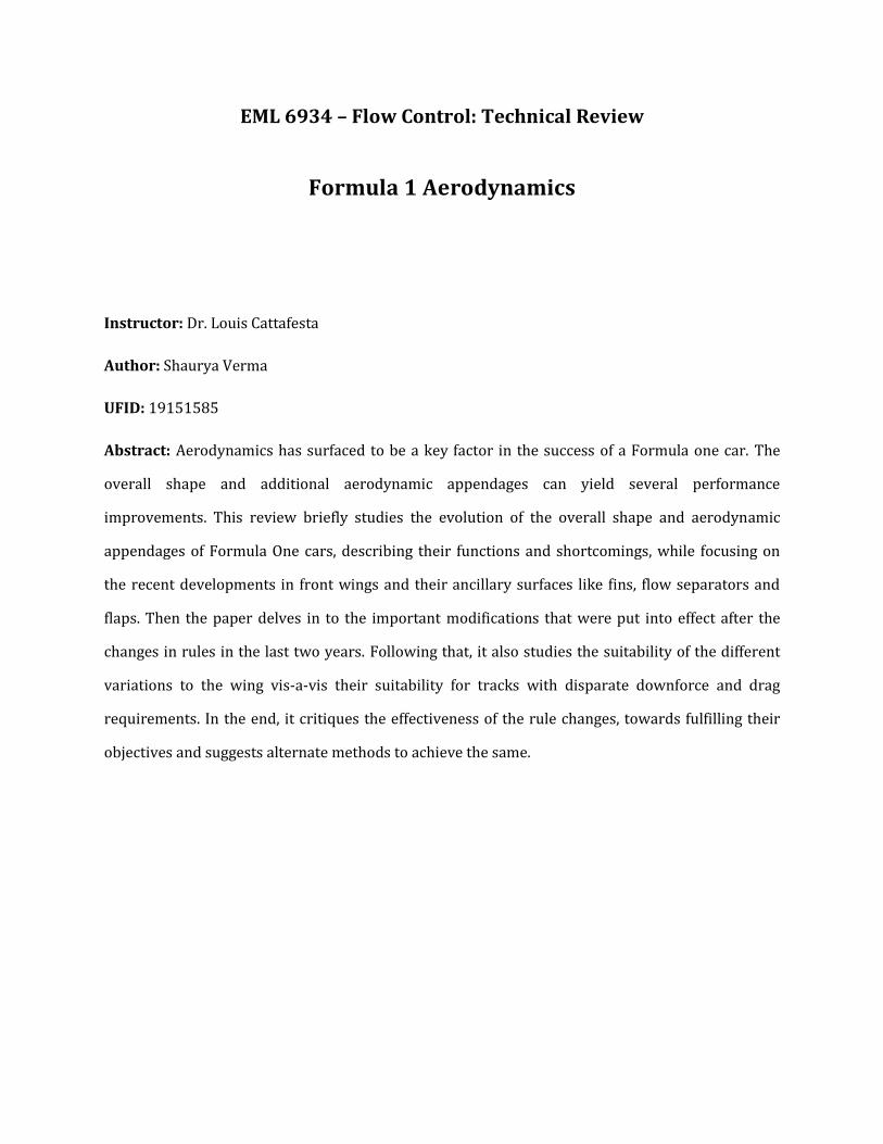
While the first front wing, introduced by Lotus in 1968 was just a rectangular airfoil (Fig 4)[23 – Sec. 2],
today’s front wings are much more complex contraptions (Fig 4). After the introduction of multi
element front wings by McLaren in 1984[5 – Sec. 5.2], almost all front wings have at least two main
elements. Owing to limitations imposed by the FIA regulations and the effect of the proximity of the
front wheels the wings are neither flat, nor with a constant chord length.
Shaurya Verma ▪ [email protected]
8 | P a g e
Fig 5: A multi element front wing of the McLaren MP4-22 (2007). Notice - three wings in the main profile and an additional bridge wing on top.[24]
Typically, the front wing generates around 25-30% of the total downforce created by the car.
However, while following another vehicle from a distance of less than twenty metres[32], the
turbulent wake of the leading car causes this to fall by around thirty percent. This loss of downforce
Fig 4: Lotus 49B: the first F1 car with a front wing (1968) [5 -Sec. 5.3].
and thus, the maximum available traction while following a car makes it harder for the pursuing car
to overtake in fast corners, where performance is mainly a function of downforce. Around slower
corners, downforce does not play a key role, and just the mechanical grip (Section 3) is decisive. On
straights, on the contrary, downforce is high, but it is not the limiting agent for speed. Straight-line
speed is largely a function of drag, and the same wake translates into a reduction in drag, thus
boosting the speed. Utilizing the wake of another car is called drafting or slipstreaming[49].
The modern front wing is generally composed of a two or more elements either in a single profile,
that is with the second airfoil very close to the trailing edge, and may also have different airfoils
parallel to each other forming a structure similar to a bi-plane. The front wing of the McLaren MP4-
22 consisted of both multi element wings oriented one after another, and also a bridge plane
running above the tip of the nosecone. (see Figure 4)
Another major update was seen in the late nineties, when teams began using flexible front and rear
wings that bent and reduced its angle of attack at high speeds, causing reduced drag on straights
without the penalty on downforce around corners. This caused a drastic upsurge in the apex speeds
possible. But, after the Johnny Herbert’s crash in Barcelona in 1999 [34], which was caused by the
Shaurya Verma ▪ [email protected]
9 | P a g e
collapse of the flexible rear wing of his Stewart-Ford, the FIA imposed a restriction on the maximum
allowable wing deflection for a given load, which is still applicable.
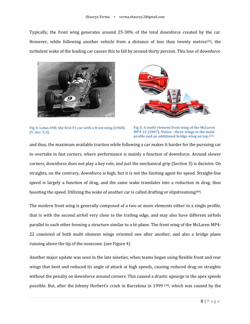
Endplates: Owing to the low aspect ratio of the front wing, it is highly prone to the influence of
wing-tip vortices and thus, induced drag. So, endplates are attached to the wingtips to curtail the
formation of undesirable vortices at both ends of the wings. More importantly, the end plates also
serve the purpose of directing the airflow away from the front wheels. Thus they are shaped like
airfoils. They either push the flow outwards, creating an outwash, or inwards, creating an ‘inwash’.
Before 2009, when the front wing was considerably narrower than the wheels, the latter was more
popular, however, after the rule changes, the former is more practical. (See section 4)
Fig 6: [Left] A diagram showing the endplates creating an inwash and an outwash[19]
. [Right] An explanation of the functioning of a front wing
[20].
An upper flap (or multiple upper flaps) is also often seen on the front wing, running parallel to and
above the main plane, from the end plate to around half the distance to the mid-point. The function
of thus auxiliary wing is primarily to condition the flow around the wheel, and thus to help reduce
the deleterious vortices induced by the wheel.
Fig 7[24]
: [Left] A complex inwash based end plate arrangement on the McLaren MP4-21 (2006) and [Right] an outwash based arrangement on the Brawn BGP001 (2009)

Shaurya Verma ▪ [email protected]
10 | P a g e
Fig. 8: Williams FW26 (2004)[24] [Photo:24]
Walrus nose: Williams designed a shorter nosecone
with tusk shaped vertical spars extending forwards
to connect to the front wing. This was done in order
to increase the airflow towards the underbody, in
order to increase downforce.[26] The new nose was,
however over-sensitive to cross-winds and was
largely unsuccessful.
The second notable element is the bottom edge outside the end-plate, which is designed as a
venturi channel to create a low pressure zone beneath it.[24]
Fig. 9: Ferrari F2004 (2004) [24] [Photo:24]
A saw tooth gurney flap at the trailing edge of the
front wing gives the additional downforce of a
Gurney flap (See section 2.8.1), with less of its drag
penalty.[24]

Shaurya Verma ▪ [email protected]
11 | P a g e
Fig. 10: Red Bull RB4 (2008) [24] [Photo:24]
Major changes shown here were for Silverstone,
which is a fast circuit.
1. Vertical fences beneath the main wing to
better manage the airflow underneath and
curtail large vortices from passing.
2. The wing was made wider, with the end-
plates extending further outwards.
After a revamp of the FIA regulations for the season 2009, the front wing changed considerably. The
following is a diagram explaining the changes in the rules related to the front wing.[24][Photo:24]
Fig. 11: Important Changes from 2008
to 2009
The front wing was made lower and
wider, thus increasing the downforce
available at the front.
A universal central section was
established, that all teams would comply
with.
Additionally, the flap section was made adjustable by the driver up to twice a lap over a range of six
degrees.[24] [Photo:24]
Shaurya Verma ▪ [email protected]
12 | P a g e
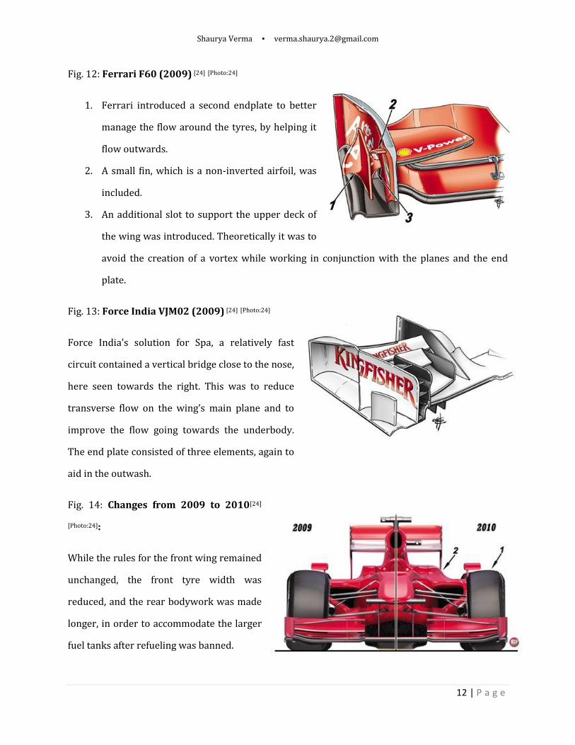
Fig. 12: Ferrari F60 (2009) [24] [Photo:24]
1. Ferrari introduced a second endplate to better
manage the flow around the tyres, by helping it
flow outwards.
2. A small fin, which is a non-inverted airfoil, was
included.
3. An additional slot to support the upper deck of
the wing was introduced. Theoretically it was to
avoid the creation of a vortex while working in conjunction with the planes and the end
plate.
Fig. 13: Force India VJM02 (2009) [24] [Photo:24]
Force India’s solution for Spa, a relatively fast
circuit contained a vertical bridge close to the nose,
here seen towards the right. This was to reduce
transverse flow on the wing’s main plane and to
improve the flow going towards the underbody.
The end plate consisted of three elements, again to
aid in the outwash.
Fig. 14: Changes from 2009 to 2010[24]
[Photo:24]:
While the rules for the front wing remained
unchanged, the front tyre width was
reduced, and the rear bodywork was made
longer, in order to accommodate the larger
fuel tanks after refueling was banned.

Shaurya Verma ▪ [email protected]
13 | P a g e
2.2 Nosecone
The early Formula One cars were all front engined [36] (till around 1961) and the front of the car
was used to house the engine radiators [9] and with little the emphasis that was laid on
aerodynamics at that time, it was large and fairly buff, designed mainly with an accent on visual
appeal (see Fig 1). Gradually, as engine displacements had restrictions imposed on them, and as
aerodynamics began to be appreciated better, the nose became more streamlined. The introduction
of rear engined cars around 1960-61 caused a further reduction the dimensions of the nose. In
1970, the revolutionary Lotus 72 introduced hip mounted radiators[25] and the function of the nose
was reduced to improving the airflow around the rest of the car. By this time the efficacy of
downforce in improving performance was well known and all noses were low with the front wing
integrated in them (Fig 3).
Fig 15: (LEFT) The low nosed Williams FW15C (champion 1993) and (RIGHT) the high nosed Benetton B195
(champion – 1995)
Although minor developments in the nose contour kept on occurring in the nose, making it more
streamlined, the next major breakthrough was in 1990 when Tyrell introduced the high nosed
Tyrell 19[5 – Sec. 5.2]. The tip of the nosecone of this car was above the plane of the front wing. While its
uninspiring performance created little excitement about the design’s efficiency, slight
improvements in suspension components and better implementation of the idea made it clear that
this was the superior design. The reason a low nose was rejected in favor its successor, was that
although the downforce achieved by more horizontal snout in isolation was admittedly lower, it
helped guide a greater volume of air underneath the car and into the diffuser, boosting the ground
Shaurya Verma ▪ [email protected]
14 | P a g e
effect (see section 2.5) and thus causing an overall increase in the downforce of the car. The
reduction in drag by the new shape was immediately evident. Additionally, since the nose did not
bisect the front wing, a larger area was available, again helping with downforce. The slight tradeoff
of the high nose was the driver’s visibility. The last low nosed car to win the driver’s or
constructor’s championship was the Williams FW15 in 1993 (Fig. 15) and by 1997 all Formula One
cars had high noses.
Till today, all cars run a high nose design, while some may be lower and closer to the front wing;
they are all connected to a full front wing by airfoil shaped spars. The sides of the nose are shaped
so as to direct the flow into the sidepods, and the top acts as a small aid in providing downforce.
All noseboxes are made of lightweight carbon fibre impregnated with resin and attached to the
monocoque. It also functions as an energy absorbing cushion in case of impact and disintegrates
into small fragments upon colliding, thus damping the blow. [9]
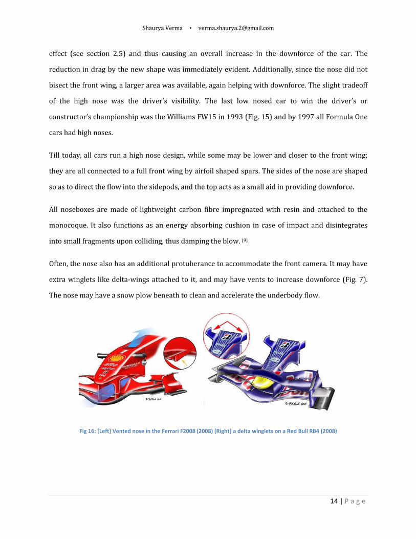
Often, the nose also has an additional protuberance to accommodate the front camera. It may have
extra winglets like delta-wings attached to it, and may have vents to increase downforce (Fig. 7).
The nose may have a snow plow beneath to clean and accelerate the underbody flow.
Fig 16: [Left] Vented nose in the Ferrari F2008 (2008) [Right] a delta winglets on a Red Bull RB4 (2008)

Shaurya Verma ▪ [email protected]
15 | P a g e
2.3 Rear Wing
The rear wing is primarily a downforce generating device attached to the car’s rear end, above the
diffuser, extending laterally between the two wheels. Working symbiotically with the diffuser, it
generally contributes about 30 to 40% of the total negative lift created by the car.
Fig 17: The Toyota Racing F1 car with a low downforce rear wing for Monza (left) and a high downforce setup for
Monaco
Unlike the front wing, the rear wing has greater leeway for variation to suit circuit requirements.
This is because, while front wing has to conform to the contours suiting the shape of the body to
maintain a smooth airflow throughout, the rear wing has fewer restrictions to be flush with the
aerodynamics of the body. Its effect is more prominent downstream, where larger variations are
tolerable. This is why; on a slow circuit like Monaco the rear wing can be inclined at a very high
angle of attack whereas at a fast circuit like Monza
it is much less steep (Fig 17). This is, however, a
rule of the thumb and different configurations can
be used to custom match the circuit characteristics
(see section 3).
The wing is attached to the car by endplates,
which, in addition to supporting the wing, also aid
in checking induced drag, which is caused by air leaking out of the wingtips from the high pressure
Fig 18: Illustrating the function of the end plates of rear wings by Shell.com
Shaurya Verma ▪ [email protected]
16 | P a g e
upper surface outwards and downwards to the low pressure lower surface thus causing trailing
vortices and drag, accompanied by a fall in the total lift. Since the wings are low aspect ratio, the
potential effect of induced drag is more prominent, and thus, the endplates, all the more
essential.(Fig 18)
2.4 Bargeboards
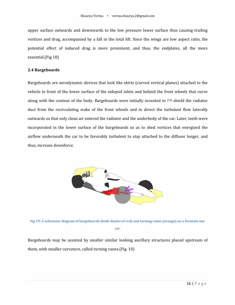
Bargeboards are aerodynamic devices that look like skirts (curved vertical planes) attached to the
vehicle in front of the lower surface of the sidepod inlets and behind the front wheels that curve
along with the contour of the body. Bargeboards were initially invented to [12] shield the radiator
duct from the recirculating wake of the front wheels and to direct the turbulent flow laterally
outwards so that only clean air entered the radiator and the underbody of the car. Later, teeth were
incorporated in the lower surface of the bargeboards so as to shed vortices that energized the
airflow underneath the car to be favorably turbulent to stay attached to the diffuser longer, and
thus, increase downforce.
Fig 19: A schematic diagram of bargeboards (both shades of red) and turning vanes (orange) on a Formula one
car.
Bargeboards may be assisted by smaller similar looking ancillary structures placed upstream of
them, with smaller curvature, called turning vanes.(Fig. 10)
Shaurya Verma ▪ [email protected]
17 | P a g e
2.5 Diffuser and the floor
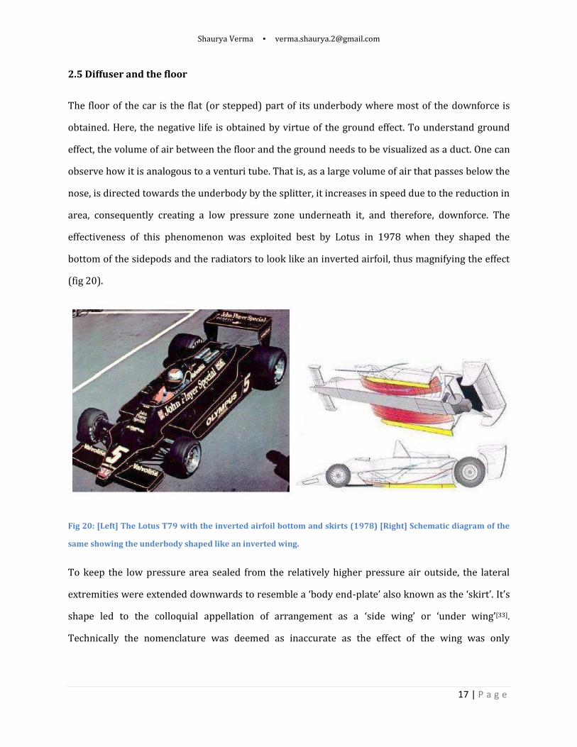
The floor of the car is the flat (or stepped) part of its underbody where most of the downforce is
obtained. Here, the negative life is obtained by virtue of the ground effect. To understand ground
effect, the volume of air between the floor and the ground needs to be visualized as a duct. One can
observe how it is analogous to a venturi tube. That is, as a large volume of air that passes below the
nose, is directed towards the underbody by the splitter, it increases in speed due to the reduction in
area, consequently creating a low pressure zone underneath it, and therefore, downforce. The
effectiveness of this phenomenon was exploited best by Lotus in 1978 when they shaped the
bottom of the sidepods and the radiators to look like an inverted airfoil, thus magnifying the effect
(fig 20).
Fig 20: [Left] The Lotus T79 with the inverted airfoil bottom and skirts (1978) [Right] Schematic diagram of the
same showing the underbody shaped like an inverted wing.
To keep the low pressure area sealed from the relatively higher pressure air outside, the lateral
extremities were extended downwards to resemble a ‘body end-plate’ also known as the ‘skirt’. It’s
shape led to the colloquial appellation of arrangement as a ‘side wing’ or ‘under wing’[33].
Technically the nomenclature was deemed as inaccurate as the effect of the wing was only
Shaurya Verma ▪ [email protected]
18 | P a g e
noticeable due to its proximity to the ground and if the wing were inserted in free flow, very little
downforce would be created.
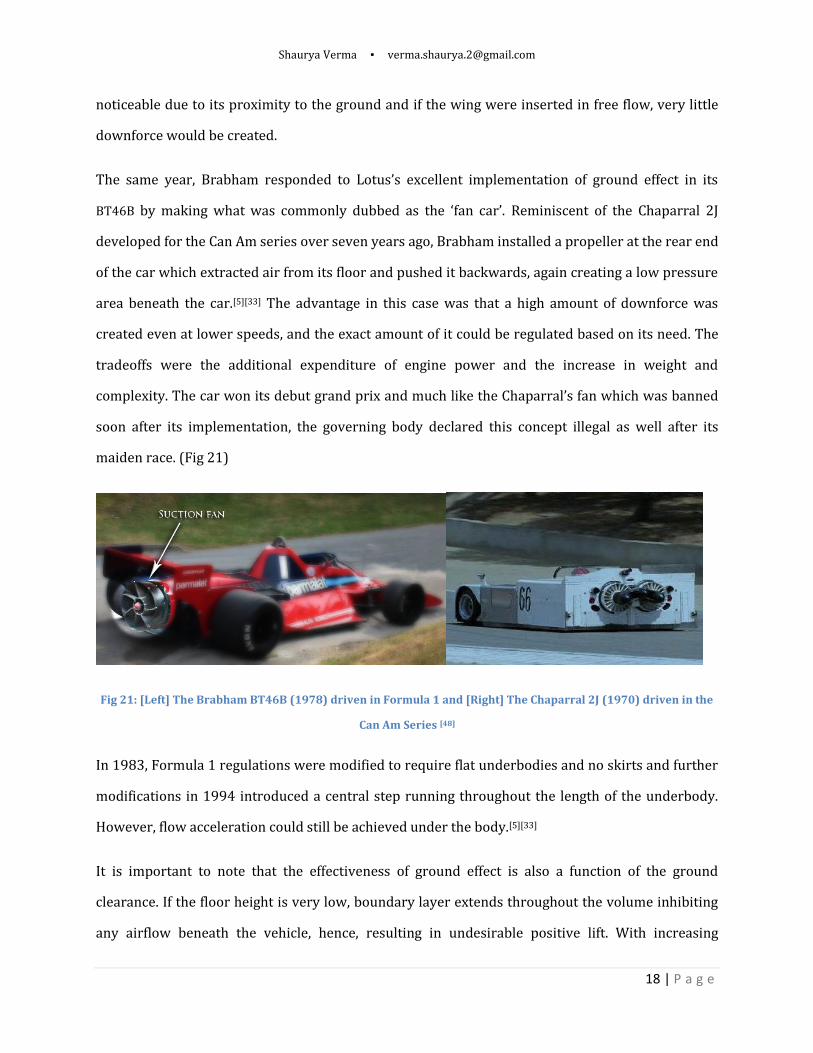
The same year, Brabham responded to Lotus’s excellent implementation of ground effect in its
BT46B by making what was commonly dubbed as the ‘fan car’. Reminiscent of the Chaparral 2J
developed for the Can Am series over seven years ago, Brabham installed a propeller at the rear end
of the car which extracted air from its floor and pushed it backwards, again creating a low pressure
area beneath the car.[5][33] The advantage in this case was that a high amount of downforce was
created even at lower speeds, and the exact amount of it could be regulated based on its need. The
tradeoffs were the additional expenditure of engine power and the increase in weight and
complexity. The car won its debut grand prix and much like the Chaparral’s fan which was banned
soon after its implementation, the governing body declared this concept illegal as well after its
maiden race. (Fig 21)
Fig 21: [Left] The Brabham BT46B (1978) driven in Formula 1 and [Right] The Chaparral 2J (1970) driven in the
Can Am Series [48]
In 1983, Formula 1 regulations were modified to require flat underbodies and no skirts and further
modifications in 1994 introduced a central step running throughout the length of the underbody.
However, flow acceleration could still be achieved under the body.[5][33]
It is important to note that the effectiveness of ground effect is also a function of the ground
clearance. If the floor height is very low, boundary layer extends throughout the volume inhibiting
any airflow beneath the vehicle, hence, resulting in undesirable positive lift. With increasing

Shaurya Verma ▪ [email protected]
19 | P a g e
clearance, better high speed airflow is attained thus creating downforce reaching a maximum
around 55mm and then the downforce begins to fall as leakage increases and the venturi effect gets
less pronounced.
Now, for an F1 car, within restrictions, in order to better tap the power of the flow beneath the car,
proper inlet and outlet are required. The inlet is the chin, beginning from the splitter and the lower
edge of the radiator inlets that gathers the flow beneath the nose and smoothly directs it below the
vehicle. The outlet, called the diffuser, which is the most critical part of the flow; is shaped like an
upsweeping rear end of the vehicle and has the sole purpose of driving the high speed air across an
adverse pressure gradient along an increasing area without separation. (see figure 22)
Fig 22: [Left] An artist's rendition of a formula one car diffuser with air flowing outwards and upwards[28]. [Right]
The diffuser of the Ferrari F430 production car installed for the same purpose[34].
This is achieved with the help of the Coanda Effect around the sidepods,[33] which is accomplished
by designing the rear of the car as a tapering contour (the proverbial ‘coke-bottle’ shape) which
guides the air flowing through the flanks (aero) to accelerate and thus become low pressured,
which helps in sucking the air upwards from the diffuser and helps prevent separation. The rear
wing and its secondary surfaces also create a low pressure area just above and downstream of the
rising flow, again preventing flow separation. Typically the floor and diffuser contribute about 35-
40 percent of the total downforce.
Shaurya Verma ▪ [email protected]
20 | P a g e
2.6 Splitter
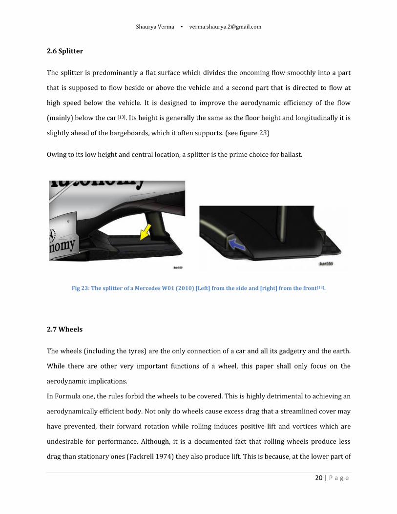
The splitter is predominantly a flat surface which divides the oncoming flow smoothly into a part
that is supposed to flow beside or above the vehicle and a second part that is directed to flow at
high speed below the vehicle. It is designed to improve the aerodynamic efficiency of the flow
(mainly) below the car [13]. Its height is generally the same as the floor height and longitudinally it is
slightly ahead of the bargeboards, which it often supports. (see figure 23)
Owing to its low height and central location, a splitter is the prime choice for ballast.
Fig 23: The splitter of a Mercedes W01 (2010) [Left] from the side and [right] from the front[13].
2.7 Wheels
The wheels (including the tyres) are the only connection of a car and all its gadgetry and the earth.
While there are other very important functions of a wheel, this paper shall only focus on the
aerodynamic implications.
In Formula one, the rules forbid the wheels to be covered. This is highly detrimental to achieving an
aerodynamically efficient body. Not only do wheels cause excess drag that a streamlined cover may
have prevented, their forward rotation while rolling induces positive lift and vortices which are
undesirable for performance. Although, it is a documented fact that rolling wheels produce less
drag than stationary ones (Fackrell 1974) they also produce lift. This is because, at the lower part of

Shaurya Verma ▪ [email protected]
21 | P a g e
the leading side, the flow separates and is at a high pressure. Also, a rotating wheel, in presence of
the ground, originates a system of three pairs of counter rotating longitudinal vortices in the wake
(Cogotti (1983) and Mercker et al. (1992)) (Fig. 1). A pair of them sheds from the top, a second from
the wheel axis and the third from the bottom, attached to the ground. This last pair of higher
intensity is called “jetting” vortices (Morelli, 2000).[14]
Fig 24: Visualization of the longitudinal structures around an isolated rotating wheel with the six vortices
shedding from it . (Mercker & Bernerburg, 1992)[36]
Although one of the functions of the front wing is to scoop away as much airflow from the front tire
as possible, and direct it, without disturbance towards the underbody and the radiators, it is not
always possible to draw an adequate amount of air away. This is particularly pronounced while
turning, when the wheels are not symmetrical and create a transverse aerodynamic force and
unbalanced moments. While this provides a minor advantage if the car has a tendency to
understeer undesirably, in most cases, an unbalanced moment only unsettles the vehicle.
Shaurya Verma ▪ [email protected]
22 | P a g e
2.8 Miscellaneous Devices
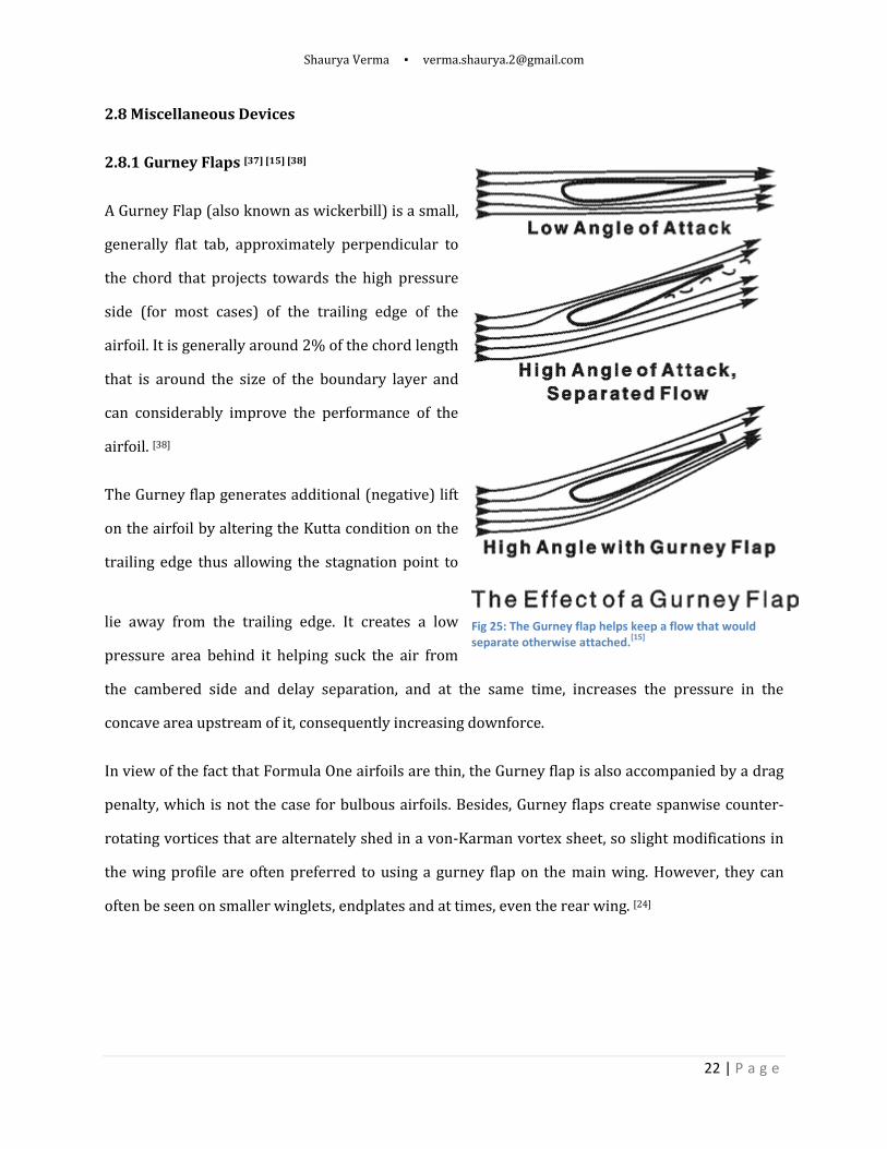
2.8.1 Gurney Flaps [37] [15] [38]
A Gurney Flap (also known as wickerbill) is a small,
generally flat tab, approximately perpendicular to
the chord that projects towards the high pressure
side (for most cases) of the trailing edge of the
airfoil. It is generally around 2% of the chord length
that is around the size of the boundary layer and
can considerably improve the performance of the
airfoil. [38]
The Gurney flap generates additional (negative) lift
on the airfoil by altering the Kutta condition on the
trailing edge thus allowing the stagnation point to
lie away from the trailing edge. It creates a low
pressure area behind it helping suck the air from
the cambered side and delay separation, and at the same time, increases the pressure in the
concave area upstream of it, consequently increasing downforce.
In view of the fact that Formula One airfoils are thin, the Gurney flap is also accompanied by a drag
penalty, which is not the case for bulbous airfoils. Besides, Gurney flaps create spanwise counter-
rotating vortices that are alternately shed in a von-Karman vortex sheet, so slight modifications in
the wing profile are often preferred to using a gurney flap on the main wing. However, they can
often be seen on smaller winglets, endplates and at times, even the rear wing. [24]
Fig 25: The Gurney flap helps keep a flow that would separate otherwise attached.
[15]

Shaurya Verma ▪ [email protected]
23 | P a g e
2.8.2 Shark Fin
First implemented in Formula One in 2008 by McLaren, the shark fin is a ridge-like extension of the
engine cover airbox extending backwards, towards the mid-point of the rear wing. It provides a
barrier between the flows from the two sides from mixing, thus curtailing the shedding of vortices
and aiding the effectiveness of the rear wing.
Fig 26: [top] A McLaren MP4-23 without a sharkfin (2008) & [bottom] McLaren MP4-23 (later in 2008) with one.
However, owing to its large profile area, it makes the car more sensitive to cross winds, resulting
additional yaw instability.
F-Duct:[39] The shark fin also forms a part of the F-Duct, which is a radical new idea that was first
designed by the McLaren Racing team in 2010. Rules banned any moveable aerodynamic surfaces,
so McLaren used the driver’s body as a moveable surface (with respect to the chassis). The chassis
had a duct which the driver’s knee could block on the straights, when additional downforce was not
required. Once blocked, the air was directed through the shark-fin via the top of the engine cover,
and blown into the slot of the rear wing elements, reducing downforce, but more importantly, drag.
This system was later emulated by other teams including Ferrari and Mercedes.
Shaurya Verma ▪ [email protected]
24 | P a g e
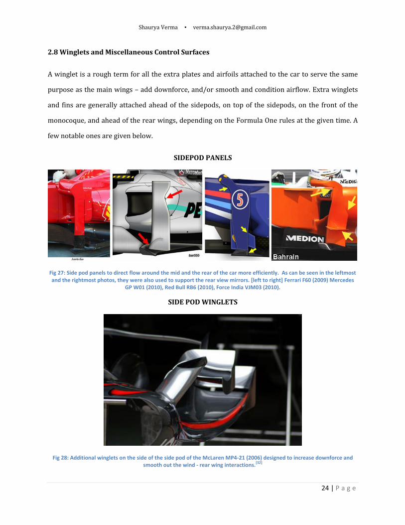
2.8 Winglets and Miscellaneous Control Surfaces
A winglet is a rough term for all the extra plates and airfoils attached to the car to serve the same
purpose as the main wings – add downforce, and/or smooth and condition airflow. Extra winglets
and fins are generally attached ahead of the sidepods, on top of the sidepods, on the front of the
monocoque, and ahead of the rear wings, depending on the Formula One rules at the given time. A
few notable ones are given below.
SIDEPOD PANELS
Fig 27: Side pod panels to direct flow around the mid and the rear of the car more efficiently. As can be seen in the leftmost and the rightmost photos, they were also used to support the rear view mirrors. [left to right] Ferrari F60 (2009) Mercedes
GP W01 (2010), Red Bull RB6 (2010), Force India VJM03 (2010).
SIDE POD WINGLETS
Fig 28: Additional winglets on the side of the side pod of the McLaren MP4-21 (2006) designed to increase downforce and smooth out the wind - rear wing interactions.
[32]
Shaurya Verma ▪ [email protected]
25 | P a g e
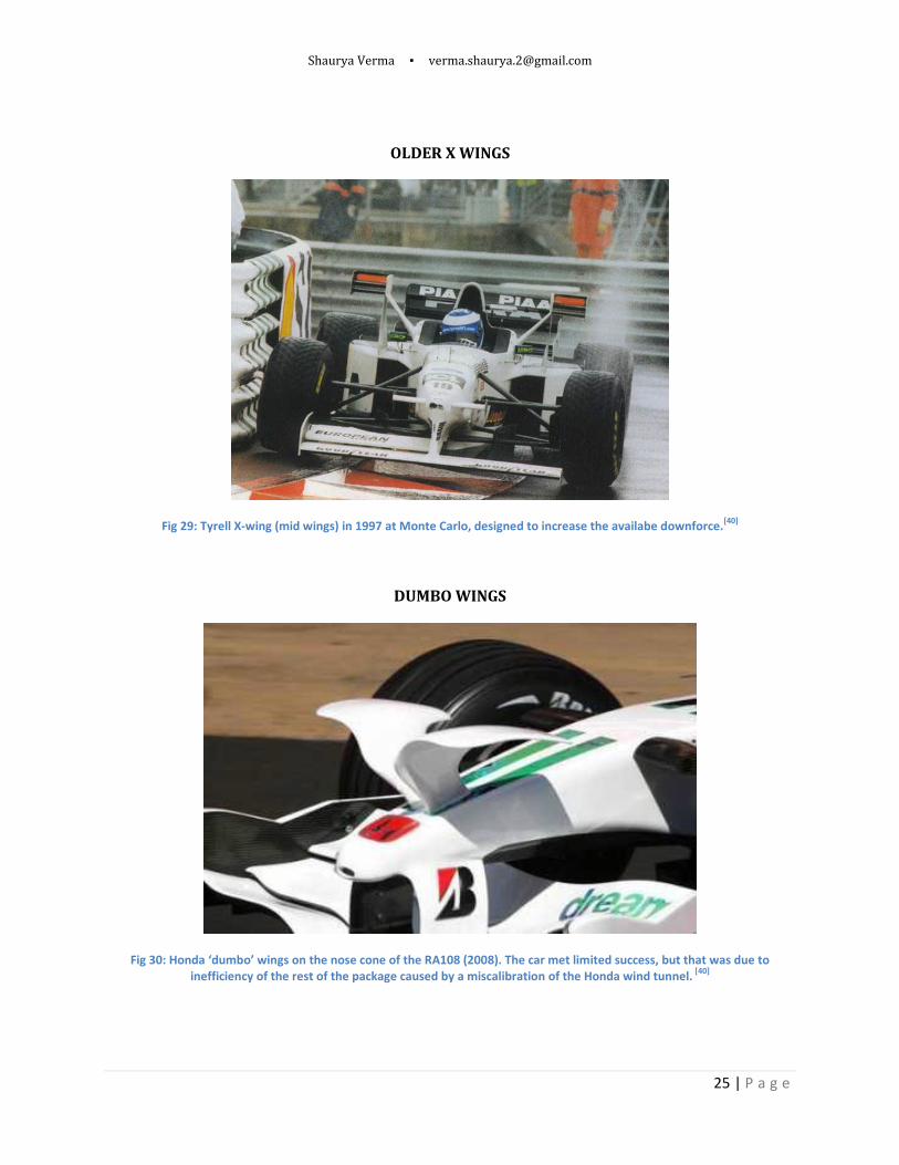
OLDER X WINGS
Fig 29: Tyrell X-wing (mid wings) in 1997 at Monte Carlo, designed to increase the availabe downforce.[40]
DUMBO WINGS
Fig 30: Honda ‘dumbo’ wings on the nose cone of the RA108 (2008). The car met limited success, but that was due to inefficiency of the rest of the package caused by a miscalibration of the Honda wind tunnel.
[40]

Shaurya Verma ▪ [email protected]
26 | P a g e
CDG WING
Fig 31: The centreline downwash generating (CDG) wing proposed as a potential solution to improve overtaking by improving the characteristics of the flow in the wake.
[27]
Fig 32: Simulation results of the CDG show lesser upflow, reducing the downforce of a car in the wake.[27]
Fig 33: Air vents, louvers, chimneys and gills on Formula One cars, usually located on the sidepods and radiators.[21]

Shaurya Verma ▪ [email protected]
27 | P a g e
RECENT MID WINGS AND ANTLERS
Fig 34: BMW antlers and horns - functioning as secondary front wings and mid wings respectively. (2008) [40]
SECOND FRONT WINGS
Fig 35: A McLaren M26 in practice in Spain (1978) testing a second front wing. [40]
McLAREN SNOW PLOUGH
Fig 36: The snow plough is a chiseled horizontal surface installed beneath the nose that acts like a diffuser mounted higher above the ground. On the upper surface, it splits the flow to go either towards the left of the right
while the flow below it is expanded and thus at a low pressure.

Shaurya Verma ▪ [email protected]
28 | P a g e
3. Track Wise Aerodynamic Variation.
The aerodynamic requirements for a fast laptime vary considerably with the conditions of the track.
The exact number and length of turns (curves), speed at the curves, length of the straights, relative
position of straights with respect to slow/fast turns, relief and banking of the track all decide the lift
v/s drag ratio that would optimize the laptime. In addition to lift/drag, it is also important to study
the moments, points of high downforce on the car and its overall balance. Aerodynamic surfaces
may be added or removed for the same to suit the different conditions.
While a slow twisty circuit like Monte Carlo (Monaco) would require greater focus on negotiating
the myriad corners fast, and thus on achieving high downforce, a fast circuit like Monza, would
necessitate keeping the drag as low as possible, so as to exploit the long straights to achieve high
average speeds.
Fig 37: [Left] Monza: the fastest circuit and [Right] Monte Carlo: the slowest circuit on the
calendar (2010)[41][42]
Nonetheless, even on medium-fast circuits, downforce can be important. In case the turns are fast
and long, speed at the turns can become the primary concern, which as explained above, is
determined by the downforce levels. Thus they may require a high downforce setup.
On the same circuit, a car that is running with a high downforce setting will be faster around
corners than a low downforce car, given the same mechanical settings, but it will lose out to the
latter on the apex speed on a long straight. However, for turns with a very low curvature, that can
be administered almost flat out (with full throttle), even faster ones, more than the requisite
downforce may be available, in such cases, again, the latter will be faster.

Shaurya Verma ▪ [email protected]
29 | P a g e
Here, it is also appropriate to talk about grip, which is also a function of the car suspension and
tyres. Grip is generally divided in to two parts: mechanical grip and aerodynamic grip. Mechanical
grip is traction obtained by the car without any effect of fluid flowing around it. It depends on mass
repartition, tyre contact area, tyre temperature, rubber adhesiveness, camber angle, and
suspension stiffness.[46] Aerodynamic grip, on the other hand is the additional grip obtained due to
downforce. While all grip is limited by the tires, downforce helps increase tyre ground adhesion.
Now, as downforce roughly increases with the square of speed, the aerodynamic grip is much more
noticeable at higher speeds, as a rule of the thumb, at greater than 60mph. Consequently, the speed
at hairpins is largely determined by the car’s mechanical grip, while the speed at spoon curves or S-
curves by aerodynamic grip.
The following is a list of the circuits used in Formula One racing in the seasons 2009 and 2010. [24]
Name Distance Time
Avg. Speed (Km/h)
Avg.Speed (Mph)
MONZA 5.793 81 257.47 159.98
SPA-BELGIUM 7.004 105.1 239.91 149.07
SILVERSTONE 5.141 78.7 235.17 146.13
SUZUKA 5.807 91 229.73 142.75
MELBOURNE 5.303 84.125 226.93 141.01
TURKISH 5.338 84.77 226.69 140.86
GERMANY 4.574 73.8 223.12 138.64
INTERLAGOS 4.309 71.5 216.96 134.81
BAHRAIN 5.412 90.25 215.88 134.14
CANADA 4.361 73.6 213.31 132.54
CHINA 5.451 92 213.30 132.54
MALAYSIAN 5.543 94 212.29 131.91
FRANCE 4.411 75.3 210.88 131.04
BARCELONA 4.655 81.67 205.19 127.50
HUNGARY 4.381 79.1 199.39 123.89
ABU DHABI 5.554 100.3 199.35 123.87
VALENCIA 5.44 98.7 198.42 123.29
SINGAPORE 5.067 105.6 172.74 107.33
MONACO 3.34 74.4 161.61 100.42
As explained above, cars run a high downforce setting on medium-fast to slow tracks, and a low
downforce setting on fast tracks. Note: the average speeds have been obtained from the best lap
Fast T
racks M
ediu
m Sp
eed T
racks Slo
w T
racks
Shaurya Verma ▪ [email protected]
30 | P a g e
figures, which depend on the rules at the time the circuits were raced on, and are thus only
indicative of its average speed.
4. Modifications in Technical Regulations
4.1 Objectives of the Modifications
Formula One technical rules and regulations are constantly updated by the sport’s governing body,
the FIA (Fédération Internationale de l’Automobile), either to seal loopholes that were not
identified earlier and led to the development of parts that were deemed unsafe or anti-competitive
or to enhance the racing and viewer experience and consequently improve the sport’s appeal,
safety, marketability, following and profit. Often sustainability of the sport and reducing the
negative ecological impact are also stated as reasons. Since rule changes cause cessation of product
development cycles, major rule modifications are rarely enforced.
This paper will only discuss the important aerodynamic changes implemented at the end of 2008,
when a host of major modifications were introduced.
The major goals stated were:
1. To control costs, thus allowing more private constructors to race.
2. To reduce the effect of the wake and facilitate overtaking
3. To develop ecological solutions of practical relevance to the world (implementation of
KERS)
4.2 Major Modifications
Final Result of the Changes[16][17][18]
1. The front wing span was increased from 1400mm to 1800mm to as to reach the extremities
of the tyres.
2. The front wing was moved forward, and turning vanes between the wheels were banned
3. Bridge wings (or full span double wings) were banned, while, half-width upper plans were
still allowed.

Shaurya Verma ▪ [email protected]
31 | P a g e
4. Nose cone: boomerang/ear/vikings wings were banned.
Fig 38: Simulation of the front view of the cars in 2008 and 2009. Control surfaces are highlighted in blue [16]
5. Winglets, cooling apertures, extensions, shark gills, between the wheels, apart from were
banned.
6. Bargeboard dimensions were reduced.
Fig 39: [top] The cars as seen from above, [middle] relative profiles of the cars [16]

Shaurya Verma ▪ [email protected]
32 | P a g e
7. The rear wing was made higher (950mm) and narrower (750mm)
Fig 40: Rear view [16]
4.3. Alternative Solutions
Improving the visual spectacle of races by increasing overtaking was one of the main objectives of
the rule changes. The rules have further been tweaked for 2011. The new rules allow the driver to
adjust the rear wing while following another driver. This is expected to find application on
straights, where it’ll allow better exploitation of the wake.
Another alternative that could possibly work is a slight modification of the proposed mechanism to
aid overtaking around corners. It is based on including a third high downforce setting. If the same
system is allowed to increase wing angles (even the front wing) when within a certain distance of
the leading car, high downforce would be available even around corners. The system could be
manual or automatic, employing an aerodynamic mapping such that the system automatically
detects the optimum angle based on the location on the circuit, employing two-way telemetry as
used for engine mapping, before it was banned in 2003.
Apart from aerodynamics, the circuit layout is also a critical factor in facilitating overtaking, as
explained by Clive Bowen (Apex Circuit Design)[43]. The major possible ways of improving
overtaking, in addition to reducing downforce are:
1. By increasing the margin for error on corners by providing run-off areas, so that there isn’t
a very high penalty for committing a mistake, drivers are encouraged to be more aggressive.
2. Having multiple racing lines through a corner with the same entry to exit time will clearly
make it easier to be fast without having to be exactly in line with the leading car.
Shaurya Verma ▪ [email protected]
33 | P a g e
3. Corner sequencing is also proposed to be an alternative. This proposes a system of corners
where the perfect line through one corner spoils entry line through the next, thus the effort
of defending one’s position successfully at one corner endangers good defense at the next.
4. Another counter-intuitive alternative proposed is based on boosting driver confidence by
increasing the available grip, as opposed to the philosophy of aiming towards reducing grip
by reducing downforce. While the latter hinges on increasing the probability of causing a
driver error, the new theory is contingent on allowing greater room for error that would
encourage drivers to take more risks. The theory proposes banking corners to accomplish
the same. An analysis of the two theories is beyond the scope of the paper.
5. Conclusion and Future Work
Formula One cars have evolved over the last sixty years from being cigar-shaped front engined
vehicles to machines with more in common with airplanes than cars. While developments have
occurred in other aspects of race car development also, the study of car aerodynamics has shot up
from being faintly understood intuition based art to an expansive scientific discourse. The
understanding of downforce and its effect on traction and performance led to a major change in the
pursuit of achieving the fastest laptime. However, due to complex fluid effects like formation of
vortices, shear layers, boundary layer transition etc. the flow is not completely understood yet and
a myriad modifications for improvement are still possible. The paper studied the major
development over the ages, with focus on the latest innovations and probed further into the
evolution of front wings.
Since little is known about the exact airfoils used in racing, the study was mainly qualitative, based
on the data made publicly available. The other aerodynamic surfaces, like the rear wing,
bargeboards could also be studied more comprehensively. A comparative discourse of the
approaches of the different constructors could also be conducted.
Shaurya Verma ▪ [email protected]
34 | P a g e
References
[1] http://www.f1technical.net/features/3893
[2] http://www.formula1.com/inside_f1/understanding_the_sport/5281.html
[3] http://en.wikipedia.org/wiki/Rumpler_Tropfenwagen
[4] http://en.wikipedia.org/wiki/Automobile_drag_coefficient
[5] Racecar Aerodynamics – Gregor Seljak (April 2008)
[6] Aerodynamics of Race Cars – Joseph Katz, San Diego State University, San Diego, California.
[7] Explanation and Discovery in Aerodynamics – Gordon McGabe (December 2005)
[8]http://www.shell.com/home/content/motorsport/ferrari/technical_partnership/f1_explained/
wing_profiles_rear/ (rear wing with or without endplates)
[9] http://f1-dictionary.110mb.com/nose_cone.html
[10] http://en.wikipedia.org/wiki/1970_Formula_One_season
[11] http://www.atlasf1.com/2000/feb16/gray.html
[12] http://f1-dictionary.110mb.com/start_page.html
[13] http://formula1techandart.wordpress.com/?s=splitter
[14] Turbulent Wake behind a Single Element Wing in Ground Effect - Xin Zhang and Jonathan
Zerihan, University of Southampton
[15] http://insideracingtechnology.com/tech104gurney.htm Paul Harney
[16] http://www.f1technical.net/articles/11878?sid=02ad3ff803ccc230adc4eb92e091f955
[17] http://www.f1technical.net/forum/viewtopic.php?f=1&t=5669
[18] http://www.fia.com/en-
GB/sport/regulations/Pages/FIAFormulaOneWorldChampionship.aspx
[19] http://f1-dictionary.110mb.com/f_w_endplate.html
[20]http://www.shell.com/home/content/motorsport/ferrari/technical_partnership/f1_explained
/wing_profiles_front/
[21] http://www.formula1.com/news/technical/
[22] http://en.wikipedia.org/wiki/Formula_One
[23] Cranfield Team F1: The front wing - F Mortel, Cranfield College of Aeronautics (2003)

Shaurya Verma ▪ [email protected]
35 | P a g e
[24] http://www.formula1.com/news/technical/
[25] http://en.wikipedia.org/wiki/Team_Lotus
[26] http://www.f1technical.net/f1db/cars/881
[27] http://www.fia.com/resources/documents/1518391260__24_10_2005_CDG_wing_2008.pdf
[28] http://www-static.shell.com/static/motorsport/imgs/544_wide/technical_partnership/
f1_explained/diffuser1.jpg
[29] http://kereta.info/wp-content/uploads/2009/02/mclaren-mp4-20-rear-diffuser.jpg
[30] www.racingrenders.com
[31] http://www.revozport.com/webpics/FERRARI/F430/Diffuser%20Fins/F430_press-
diffuser.jpg
[32] Les Dossiers Techniques de F1-Forecast – Dominique Madier
[33] Explanation and discovery in aerodynamics - Gordon McCabe (December 2005)
[34] http://www.f1fanatic.co.uk/2007/01/25/banned-flexi-wings/
[35] http://en.wikipedia.org/wiki/History_of_Formula_One
[36] Flow analysis around a rotating wheel - Emmanuelle Thivolle-Cazat, Patrick Gilliéron (June
2006)
[37] Aerofoil at low speeds with Gurney flaps - L. Brown and A. Filippone (Sept 2003)
[38] http://en.wikipedia.org/wiki/Gurney_flap
[39] http://www.racecar-engineering.com/articles/f1/449813/f-ducts-how-do-they-work.html
[40] http://www.gtplanet.net/forum/showthread.php?t=125471
[41] http://en.wikipedia.org/wiki/Monaco_Grand_Prix
[42] http://en.wikipedia.org/wiki/Autodromo_Nazionale_Monza
[43] http://www.racecar-engineering.com/news/opinion/446922/f1-overtaking-are-the-circuits-
to-blame.html
[44] http://www.modified.com/news/0708_sccp_lateral_g_skidpad_testing/skidpad.html
[45] http://en.wikipedia.org/wiki/Chaparral_Cars
[46] http://en.wikipedia.org/wiki/Downforce

Shaurya Verma ▪ [email protected]
36 | P a g e
[47] The Influence of Aerodynamics on the Design of High-Performance Road Vehicles - Part 2, by
Guido Buresti, University of Pisa (Italy), March 2004
[48] Race Car Aerodynamics – Corrado Casiraghi, Royal Institute of Technology, Stockholm, May
2010.
[49] http://en.wikipedia.org/wiki/Drafting_(aerodynamics)
[50] Aerodynamic effectiveness of the flow of exhaust gases in a generic formula one car configuration - F. L. Parra and K. Kontis, University of Manchester, September 2006