formti-12 b-t-3239 corrosion resistance and
TRANSCRIPT

t b
FORMTI-120711999
B-T-3239
Corrosion Resistance and Electrochemical Potentiokinetic Reactivation TestingOf Some Iron-base Hardfacing Alloys
B.V. Cockeram
USDOE contract No. DE-ACI 1-98 PN38206
This report was prepared as an account of work sponsored by the United States Government. Neitherthe United States, nor the United States Department of Energy, nor the United States Navy, nor any oftheir employees, nor any of their contractors, subcontractors, or their employees, makes anywarranty, express or implied, or assumes any legal liability or responsibility for the accuracy,completeness or usefulness of any information, apparatus, product or process disclosed, orrepresents that its use would not infringe privately owned rights.
I I
BETTIS ATOMIC POWER LABORATORY WEST MIFFLIN, PENNSYLVANIA 15122-0079
Operated for the U.S. Department of Energyby Bechtel Bettis, Inc.

DISCLAIMER
Portions of this document may be iUegibIein electronic image products. Images areproduced from the best avaiiable originaldocument.

Corrosion Resistance and Electrochemical Potentiokinetic Reactivation Testing
of Some Iron-base Hardfacing Alloys
B.V. Cockeram, Bettis Atomic Power Laboratory, Bechtel-Bettis, Inc., P.O. Box 79, West Mifflin,
PA 15122-0079.
Abstract
Hardfacing alloys are weld deposited on a base material to provide a wear resistant
surface. Commercially available iron-base hardfacing alloys are being evaluated for
replacement of cobalt-base alloys to reduce nuclear plant activation levels. Corrosion testing
was used to evaluate the corrosion resistance of several iron-base hardfacing alloys in highly
oxygenated environments. The corrosion test results indicate that iron-base hardfacing alloys in
the as-deposited condition have acceptable corrosion resistance when the chromium to carbon
ratio is greater than 4. Tristelle 5183, with a high niobium (stabilizer) content, did not follow this
trend due to precipitation of niobium-rich carbides instead of chromium-rich carbides. This result
indicates that iron-base hardfacing alloys containing high stabilizer contents may possess good
corrosion resistance with Cr:C c 4. NOREM 02, NOREM 01, and NoCO-M2 hardfacing alloys
had acceptable corrosion resistance in the as-deposited and 885°C/4 hour heat treated
condition, but rusting from sensitization was observed in the 621 OC/6 hour heat treated
condition.
The feasibility of using an Electrochemical Potentiokinetic Reactivation (EPR) test
method, such as used for stainless steel, to detect sensitization in iron-base hardfacing alloys
was evaluated. A single loop - EPR method was found to provide a more consistent
measurement of sensitization than a double loop - EPR method. The high carbon content that is
needed for a wear resistant hardfacing alloy produces a high volume fraction of chromium-rich
carbides that are attacked during EPR testing. This results in inherently lower sensitivity for

,
detection of a sensitized iron-base hardfacing alloy than stainless steel using conventional EPR
test methods.
INTRODUCTION
Hardfacing alloys are thick, multilayer weld deposits (0.2 to 0.5 cm thick) that provide
wear resistance to a structural base metal’. The common use of cobalt-base hardfacing alloys
on nuclear plant components results in high plant radiation levels from activated cobalt wear and
corrosion debris2. The wear and corrosion of cobalt containing alloys produces cobalt debris
that are circulated in the primary coolant through the reactor core where 59C0 is transmuted to
‘°Co, which possesses a high and long lived nuclear activity. The deposition of ‘°Co debris on
nuclear plant components results in high radiation fields, which makes the maintenance and
disposal of nuclear plant components both hazardous and costly. Replacement of cobalt-base
hardfacings with a no-cobalt alloy would significantly reduce the costs associated with nuclear
plant activation from ‘°Co. Testing of commercial nickel-base and iron-base hardfacing alloys
shows that iron-base alloys generally possess better galling wear resistance and more favorable
fracture toughness values, but none of these hardfacing alloys exhibited properties comparable
to the cobalt-base hardfacing alloy of choice, Steilite 63’4. Excellent corrosion resistance in a
nuclear plant environment is required for any material considered for use in nuclear plant
applications, and some iron-base hardfacing
humid environment5.
alloys have exhibited poor corrosion resistance in a
Corrosion screening of hardfacings is typically performed in highly oxygenated
environments because these conditions are more severe5. Exposure a humid environment
resulted in rusting of two commercial iron-base alloys (Delcrome 910, and Everit 50) with more
severe attack observed for specimens that were given a 621 OC/6h stress relief (SR) heat
treatment. The corrosion resistance of as-deposited NOREM 01 in a humid environment was
acceptable, but rusting was observed for NOREM 01 coupons that had been given a 6210C/6h
heat treatment. NOREM 01 is an early variant of NOREM hardfacing alloys which were
2
.- . . ..— .-. ..- . . . ~.-—--- . . -. ..

developed through the Electric Power Research institute (EPRI), and are based upon the galling
resistant stainless steel Nitronic 60 (ARMCO Steel)G. The degradation in the corrosion
resistance of iron-base hardfacing alloys such as NOREM 01 from the 621 OC/6h heat treatment
is a form of sensitization.
Electrochemical potentiokinetic reactivation (EPR) is a rapid and quantitative method for
detecting sensitization in austenitic stainless steels’-g, duplex stainless steels’”, and Alloy 600”.
The ASTM GI 08-92 test method is a single loop-EPR (SL-EPR) test7; a large over-potential is
initially applied to passivate the sample, and the reactivation scan is used to characterize the
degree of sensitization. The reactivation cathodic scan produces preferential breakdown of
regions that are deficient in chromium and these sensitized regions are detected by the area
under the reactivation curve, which is proportional to the total measured charge (Q in
coulombs/cm2). The total grain boundary area (GBA) is determined by measuring the grain size
GBA= A, [ 5.09544X 10⁻³exp(O.34696 X)] (1)
(ASTM grain size number (X)) for the specimen test area (AJ7.
(2)QPa=—
GBA
A high value of P, indicates sensitization for the SL-EPR test
Since the SL-EPR test method is very sensitive to experimental variables such as scan rate,
surface finish, solution temperature, solution purity, and grain size measurement, a Double Loop
- EPR (DL-EPR) method was initially used in this work8)9. Both the anodic and reactivation
scans are used in the DL-EPR test, and high values of the ratio of the maximum current density
for the reactivation scan (1,)to the anodic scan (IJ or 1;1, indicates sensitization.
The purpose of this work is to evaluate the corrosion resistance of as-deposited and heat
treated iron-base hardfacing alloys in highly oxygenated environments, and determine
3

temperature/time conditions that produce sensitization. Two more recent variants of NOREM
alloys (NoCO-M2 and NOREM 02) and a vanadium-containing Fe-base hardfacing alloy
(ELMAX) are evaluated. A feasibility study on the use of an EPR method to detect sensitization
in NOREM hardfacing alloys is also reported.
EXPERIMENTAL
Materials
The hardfacing alloys (NOREM 01, NOREM 02, NoCO-M2, ELMAX, and Stellite 6) were
weld deposited onto Alloy 600, AISI type 304, and/or AISl type 347 stainless steel bar (19.1 cm
X 3.8 cm X 2.5 cm thick) using Plasma Transferred Arc Welding (PTAW) with a minimum
preheat of 371 “C. NOREM 01, ELMAX, and Stellite 6 were only PTAW deposited on AISI type
347 stainless steel. Stellite 6, the cobalt-base alloy of choice, was tested as a reference
material. Two-layers of each hardfacing alloy were deposited to a total nominal thickness of 0.5
cm to minimize dilution from the base material. Comparison of the weld consumable chemistry
and deposit chemistry in Table 1 shows that the difference in elemental concentration was
generally less than 10YO,which is consistent with the low base metal dilution characteristic of
PTAW deposition’. Slightly higher increases in nickel were observed for the NoCO-M2 and
NOREM 02 deposits made on Alloy 600, which results from base metal dilution with the nickel-
base alloy. The lower nitrogen content for deposits made on Alloy 600 is not clearly understood.
Hardfacing deposits of NOREM 02, NoCO-M2, ELMAX, and Stellite 6 were tested in the as-
deposited, 1150 SR, and 1625 SR stress relief (SR) heat treatment conditions given in Table 2.
The hardfacing deposits were given a stress relief (SR) heat treatment prior to machining
specimens.
4
Corrosion Testing
Corrosion coupons shown in Figure 1 were machined from the hardfacing deposits in
accordance with Figure 2. Spare material from the NOREM 02 and NoCO-M2 deposits made on
Alloy 600 and type 304 stainless steel were used for the chemistry measurements in Table 1.
Any oxide scale was removed and only the top 0.10 cm of the hardfacing deposit was used for
chemical analysis. The corrosion test consisted of a 4 week exposure to a humid environment
with an interim examination followed by an 1 day exposure to highly oxygenated water, see
Table 3. Weight change measurements, visual examinations, and metallographic sectioning
were
EPR
used to evaluate the condition of specimens after the corrosion test.
Tests
EPR test coupons (1 cm X 1 cm X 0.2 cm thick) were machined from the hardfacing
deposits, and contain no base metal. The NoCO-M2 and NOREM 02 EPR coupons were
machined from the same deposit used in corrosion testing, see Figure 2. The NOREM 01
coupons were machined from the same lot of hardfacing deposits previously used for corrosion
testing5. Three EPR tests were performed on each alloy for a total of 24 individual tests: (1)
NOREM 01 in the as-deposited and 1150 SR conditions; (2) NoCO-M2 in the as-deposited, 1150
SR, and 1625 SR conditions; and (3) NOREM 02 in the as-deposited, 1150 SR, and 1625 SR
conditions. The surfaces of the working electrodes (WE) were examined after EPR testing using
optical microscopy, and compared with metallography from corrosion testing.
The EPR test procedure generally conforms with ASTM GI 08-927. The characteristics of
the potential and current measuring instrument were in accordance with ASTM G5-87’2 over the
potential range used (-600 mV to +700 mV (Saturated Calomel Electrode (SCE) Reference)). A
deaeration tube was not used in the test cell, but all other features of the test cell, SCE reference
electrode, electrode holders, etc., were in accordance with ASTM G5-87’2. A platinum coated
niobium mesh was connected to a platinum coated titanium rod and used as the counter
electrode. Electrical contact with the back of the working electrode (WE) was achieved by using
5
.,.., ,,-.,m?—-------ra-,.. , . . .,,. r--- ... . .+7$.,T-rn7- 7, 27 r.. . . . .~. c ~-,. ,- --’,, ;-. 2.> .. ... --w-----

silver paste and then epoxy to attach a stainless steel machine screw. A nickel ribbon intended
to provide electrical connection was spot welded to the end of the screw prior to attachment of
the screw to the specimen. The screw and nickel ribbon were isolated from the electrolyte test
solution by a 1/4” glass tube that was attached to the back of the sample coupon. The WE was
mounted in epoxy and then polished through 1 Vm diamond within 1 hour of the experiment, and
cleaned prior to testing by decreasing in Alconox detergent, rinsing in distilled water, rinsing with
reagent grade methanol, and air drying. The test solution was prepared from reagent grade
sulfuric acid (H2S04), potassium thiocyanate (KSCN), and Type IV water as a 0.5 M H2S04 +
0.02 M KSCN test solution. A quantity of 0.5 liters of test solution was used for each test cell,
and the temperature was maintained at 30 A 1“C with a controlled temperature water bath.
The open circuit potential (OCP or E(initial)) was recorded within 1 to 2 minutes after
immersion in the test solution. An increasing potential was then applied to the WE at a rate of
1.67 * 0.08 mV/s (6 V/h) until a maximum potential of +500 mV was reached for the anodic
scan. The reactivation scan was immediately started by decreasing the potential at a rate of 1.67
* 0.08 mV/s to the initially measured OCP. The OCP was measured after the reactivation scan
was completed (E(rest)). The WE voltage and resulting current were continuously measured
during the anodic and reactivation scans, and the maximum current density for the anodic scan
(IJ and reactivation scan (IJ were each determined from the recorded data files. The area under
the reactivation scan portion of the curve after passive breakdown was also obtained from the
data files to determine the total charge (Q in Eq. (2)) for SL-EPR characterization.
RESULTS AND DISCUSSION
Corrosion Testing
Small weight changes observed after exposure to the highly oxygenated conditions (-5
mg/dm2 to 5 mg/dm2) indicate that the degree of tarnishing was small, and visual examinations
were used to characterize the corrosion. After exposure to a humid environment, NoCO-M2 and
NOREM 02 coupons in the as-deposited condition were shiny and similar in appearance to
6
,., ,.-.. .----- . ..... --7 .=. . . -.rm.zm-. r- ,, . . .. >- T?=---

stainless steel, see Figures 3a and 3b. Rust spots were observed on ELMAX in the as-
deposited, 1150 SR, and 1625 SR conditions, which indicates that this alloy has unacceptable
corrosion resistance. Rusting was previously observed for as-deposited Everit 50 and
Delcrome 910 after exposure to a humid environment, but as-deposited NOREM 01 had
acceptable corrosion resistance. Examination of the nominal compositions in Table 1 indicates
that hardfacing alloys with low CCC ratios generally have poor corrosion resistance. Since
molybdenum generally improves corrosion resistance, while nitrogen can precipitate with carbon,
an effective Cr:C ratio (CORR) is defined (in atomic%)
~oRR %Cr -!- 9ZOM0
= %C+%iv(3)
The plot of CORR values versus general corrosion resistance for as-deposited hardfacing alloys
in Figure 4 shows that hardfacing alloys with CORR c 4 exhibit rusting in a humid environment,
with the exception of Tristelle 5183. Iron-base hardfacing alloys have a high carbon content to
produce the high volume fraction of interdendritic chromium-rich carbides that is needed for
wear resistance. However, iron-base hardfacing alloys with low CORR values apparently do not
have enough chromium remaining in solution to provide for corrosion resistance after
precipitation of these interdendritic chromium-rich carbides. Tristelle5183 contains a large
amount of niobium, which is a stabilizer. The niobium in Tristelle 5183 forms the more stable
Nb-carbide rather than Cr-carbide. The resulting precipitation of large, coarse Nb-rich carbides
avoids excessive Cr-carbide precipitation to leave chromium in solution to provide corrosion
resistance. This result indicates that hardfacing alloys with high stabilizer contents can have
acceptable corrosion resistance with lower CORR values. However, exposure to highly
oxygenated water produced significant selective phase attack (SPA) of the large Nb-rich
carbides in Tristelle 51835. As-deposited NOREM 02 and NoCO-M2 exhibited good corrosion
resistance in highly oxygenated water, while severe attack was observed for ELMAX. The
7
relationship between CORR and corrosion resistance in Figure 4 is empirical, and more work
would be needed to define a general relationship between corrosion resistance and alloy
composition.
Figure 3 shows that the 1625 SR coupons for NOREM 02 and NoCO-M2 were similar in
appearance to the respective as-deposited coupons. Rust spots are observed for the 1150 SR
condition for NoCO-M2 and NOREM 02 in Figures 3a and 3b, respectively. The NoCO-M2 and
NOREM 02 coupons shown in Figure 3 were deposited on type 347 stainless steel, but similar
results were observed for NoCO-M2 and NOREM 02 deposited on type 304 stainless steel and
Alloy 600. PTAW hardfacing deposition results in low base metal dilutionl, and the chemistries
of NoCO-M2 and NOREM 02 deposits made on type 304 stainless steel or Alloy 600 in Table 1
are comparable, which results in no dependence of base metal on corrosion resistance. The
results previously observed for NOREM 01 after exposure to a humid environment were similar
to those observed for NoCO-M2 and NOREM 02: (1) good corrosion resistance for the as-
deposited condition, and (2) rusting observed for the 1150 SR condition.
The rusting of the 1150 SR condition of NOREM 01, NoCO-M2, and NOREM 02 is
produced by a form of sensitization, or chromium-carbide precipitation that depletes the
dendrites of the chromium needed for corrosion resistance. The temperature range for
sensitization of NOREM hardfacings is estimated in Figure 5 to be the same as that observed in
austenitic stainless steels, 51 O“C to 790”C (950” F to 1450” F)13. Extended exposure in the
temperature range for sensitization explains the rusting observed for NOREM hardfacings in the
1150 SR condition. Faster cooling of as-deposited NOREM alloys through the 51 O°C to 790”C
temperature range avoids sensitization, which explains their excellent corrosion resistance.
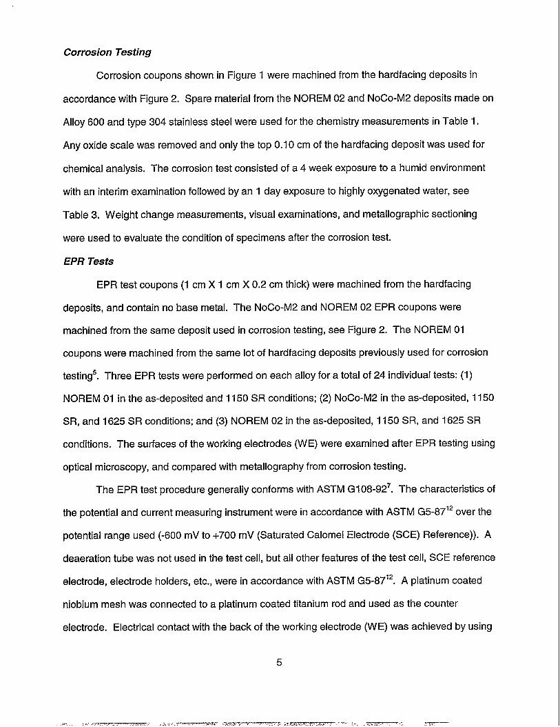
Figures 6a and 6b show that the as-deposited NOREM 02 microstructure consists of an
interdendrite matrix of carbide/austenite Iamella which surrounds dendrites. The dendrites
consist of austenite surrounding a &ferrite core with coarse carbide precipitates. The presence
of &ferrite was confirmed by ferro-magnetism detected with a high strength Co-Sin magnet3’G.
8
.,,, .,---- , m.. , ,.., ,,...-.- .. r.< . . . ,--= J .:. -.7 . .. . .

Little change in the scale of the dendrite and interdendrite regions is produced by the 1150 SR
of NOREM 02, but Figure 6C shows coarse precipitates in the dendrites. These precipitates are
likely chromium-carbide precipitates that have formed and coarsened in the dendrites during the
1150 SR to result in chromium depleted regions and rusting after exposure to a humid
environment. The 1625 SR produces little coarsening of the microstructure, but dense
precipitation is observed in the dendrites. Heat treatment of NoCO-M2 and NOREM 02 above
the temperature range for sensitization during a 1625 SR results in re-solution of the chromium-
carbide precipitates, and chromium-carbide precipitation occurs during slow cooling through the
temperature range for sensitization to produce the dense precipitation shown in Figure 6d.
Although dense precipitation is observed in the dendrites, the cooling rate is apparently too fast
to result in sufficient chromium depletion that decreases the corrosion resistance.
The microstructure for NoCO-M2 and NOREM 01 were generally similar to NOREM 02
with the following exception: (1) higher dendrite volume fraction for NoCO-M2, and a much lower
fraction of &ferrite in the dendrites, and (2) no &ferrite in the NOREM 01 dendrites but the
dendrite volume fraction was similar to NOREM 02. Although the &ferrite content in the
dendrites varied for NOREM 02, NoCO-M2, and NOREM 01, the precipitate density in the
dendrites for the 1150 SR and 1625 SR conditions were similar. The 1150 SR produced rusting
for NOREM 02, NoCO-M2, and NOREM 01, while good corrosion resistance was observed for
the as-deposited and 1625 SR conditions, which indicates that the &ferrite content of the
dendrites has little influence on corrosion resistance. These preliminary metallographic results
indicate that precipitation and coarsening of the Cr-carbide precipitates during the 1150 SR
apparently decreases the chromium content below the levels needed for corrosion resistance
and results in sensitization in NOREM hardfacing alloys. However, the dense chromium-carbide
precipitation in the dendrites for the 1625 SR in NOREM hardfacings does not produce
sensitization.
9

EPR Feasibility Test Results
Since the DL-EPR test method is reported to be less sensitive to specimen preparation
and produces less scatter, the DL-EPR test approach was initially pursued. Example
polarization curves for one DL-EPR test of NOREM 02 (as-deposited, 1150 SR, and 1625 SR)
are given in Figures 7a, b, and c, respectively. Data for all 24 DL-EPR tests are compiled in
Table 4. Since partial breakdown of the passive film was produced during the reactivation scan,
the corrosion potential after completion of the test (E(rest)) was higher than the initial potential
(E(initial)). The summary plot in Figure 8 shows that the l~la values for 1150 SR (sensitized)
NOREM 02 and NoCO-M2 were generally higher than 0.5. The 1,:1.values for the 1150 SR
condition of NOREM 01, NOREM 02, and NoCO-M2 are larger than the respective as-deposited
and/or 1625 SR conditions, but the values for as-deposited and 1150 SR NOREM 01 over lap.
The DL-EPR test can be used to differentiate between un-sensitized and sensitized conditions
for NOREM 02 and NoCO-M2, but the sensitized condition was not resolved for NOREM 01.
The Iila values for the 1625 SR conditions given in Figure 8 are significantly less than the
respective as-deposited and 1150 SR conditions for NOREM 02 and NoCO-M2, which indicates
that the 1625 SR is the least sensitized, which is not consistent with previous test results and
microstructure examinations, i.e. dense Cr-carbide precipitation in the dendrites of 1625 SR
NOREM 02 in Figure 6d. For stainless steels, 1;1, values greater than 0.1 are considered to be
sensitized8’g’14”5, which is much less than the values measured in Table 4 for as-deposited
NOREM hardfacing alloys. The higher volume fraction of Cr-carbides in NOREM hardfacings,
which are attacked during the DL-EPR test, produces inherently higher l~la values and less
sensitivity for detection of a sensitized iron-base hardfacing alloy.
The low sensitivity for the DL-EPR method results from higher 1.values for the 1150 SR
and 1625 SR conditions compared to as-deposited, which result in less difference in l;l~ values
between the non-sensitized (as-deposited and 1625 SR) and sensitized (1 150 SR) conditions.
The higher la values for1150 SR and 1625 SR in Table 4 likely result from attack of the
10
chromium-depleted regions in the dendrites. In order to remove the data bias resulting from the
higher la values, the data curves were analyzed as a SL-EPR test by calculating the area under
the reactivation curves after de-passivation to determine specimen charge (Q in Eq. (2)). The
correction for grain size in Eq. (2) was not made, and the reported Pa values given in Table 4 are
only charge (Q) divided by sample area. Since the as-deposited, 1150 SR, and 1625 SR
conditions for each alloy were produced from the same heat of weld consumable using the same
weld deposition parameters, large differences in the scale of microstructure are not expected.
The hardfacing alloys consist of dendrites separated by interdendritic regions of
carbide/austenite Iameila and determination of grain size in terms comparable to stainless steels
is difficult. Comparison of SL-EPR data in Figure 9 and Table 4 shows that the Pa difference
between the as-deposited and 1150 SR conditions was more than a factor of 2 for NOREM 02
and NoCO-M2. Although the P. differences between as-deposited and 1150 SR NOREM 01
were less than a factor of 2, the difference was more significant than the DL-EPR test. The SL-
EPR results indicate that the 1625 SR condition was more sensitized than the as-deposited
condition, but either significantly less sensitized than the 1150 SR condition (NoCO-M2) or only
slightly less sensitized than the 1150 SR condition (NOREM 02). The trend of Pa values for as-
deposited, 1150 SR, and 1625 SR condition for NOREM 02 and NoCO-M2 in Figure 9 were
consistent with the corrosion test results: (1) 1150 SR (heavily sensitized), (2) 1625 SR (mildly
sensitized), and (3) as-deposited (least sensitized). Based on the results of the SL-EPR scan
data shown in Figure 9, a line at P, = 1.5 C/cm2 was arbitrarily drawn to mark the boundary
between the sensitized and unsensitized conditions. With the exception of one data point for
1150 SR NOREM 01, ail data points in the “Non-Sensitized Zone” are not sensitized.
Additionally, with the exception of one data point for 1625 SR NOREM 02, all data in the
“Sensitized Zone” were sensitized and rusting was observed after exposure to a humid
environment. Based on round-robin testing7, type 304 stainless steel is characterized as
sensitized if P.> 0.4 C/cm2. The higher carbon and chromium contents of NOREM hardfacing
11

alloys produce a large volume fraction of chromium-rich carbides that are subject to
electrochemical attack and, consequently, inherently higher Pa values.
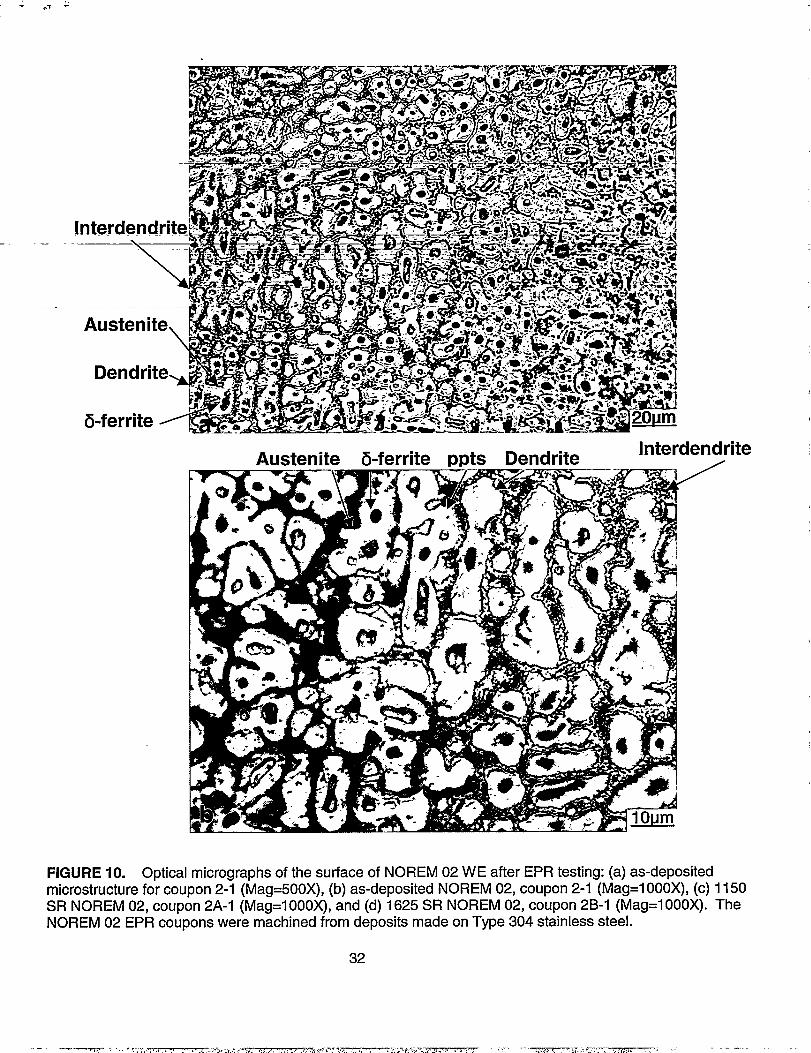
EPR testing resulted in preferential attack of chromium-rich carbides in the interdendritic
carbide/austenite Iamella and &ferrite regions in the center of the dendrites for as-deposited
NOREM 02 in Figures 10a and 10b. Infrequent localized attack of coarse Cr-carbide
precipitates in the austenite regions of the dendrites, which surround the &ferrite regions, is also
observed for as-deposited NOREM 02. Micrographs of corrosion coupons machined from the
same hardfaced deposit (Figures 6a and 6b) show that the microstructure was similar to the
Working Electrode (WE). The chromium-rich carbides (mostly MTC3) in the interdendritic
regionsG likely represent inclusions that are subjected to selective attack during the EPR test.
The &ferrite regions in the dendrites probably contain a high density of carbide precipitates, due
to the low volubility of carbon in &ferrite, that are subjected to selective attack in the EPR
solution. Coarse Cr-carbide precipitates only infrequently occur in the austenite regions of the
dendrites in as-deposited NOREM 02 due to the high cooling rate, and these coarse carbide
precipitates or chromium-depleted regions adjacent to the carbides appear to be attacked by the
EPR solution. This wide attack of the interdendritic carbides and dendritic regions for as-
Similar appearance was observed for
deposited NOREM 02 likely results in the inherently higher 1;1. and Pa values for as-deposited
NOREM 02, even though this material was not sensitized.
the WE of as-deposited NoCO-M2 and NOREM 01.
The microstructure of the WE for 1150 SR NOREM 02 shown in Figure 10c exhibits
features that were generally similar to those observed for as-deposited NOREM 02, but more
extensive attack of coarse Cr-carbide precipitates or Cr-depleted regions in the dendrites was
observed for 1150 SR NOREM 02. Large Cr-carbide precipitates in austenite dendrite regions
and dense Cr-carbide precipitates in the &ferrite regions of the dendrites is observed in the
1150 SR NOREM 02 microstructure shown in Figure 6c. Cr-carbide precipitation and
coarsening in the dendrites during the 6210C/6h SR heat-treatment in the temperature range for
12

sensitization (Figure 5) produces numerous Cr-depleted regions in the dendrites. The attack of
these regions during the reactivation scan gives higher l& and Pa values for 1150 SR. Since
the only significant differences between 1150 SR and as-deposited is the greater frequency of
Cr-depleted regions in the dendrites of the 1150 SR material, the differences in I;la (Figure 8)
and Pa (Figure 9) values are not large. The microstructure of the WE for 1150 SR NoCO-M2 and
NOREM 01 exhibited similar features.
The three WES for 1625 SR NOREM 02 appeared similar to as-deposited NOREM 02,
but the etching of the 1625 SR dendrites appeared more significant and uniform than observed
for as-deposited and 1150 SR NOREM 02. The microstructure for 1625 SR NOREM 02 shown
in Figure 6d consists of Cr-carbide/austenite Iamella regions that separate dendrites which
contain a dense distribution of fine Cr-carbide precipitates from slow cooling through the
temperature range for sensitization (Figure 5). Although a high precipitate density was observed
in the dendrites of 1625 SR NOREM 02, the local chromium-depletion produced by the dense
precipitation did not produce a significant degradation in corrosion resistance. The slight
sensitization that results from the 1625 SR can be detected using the SL-EPR test, but the wide
data scatter shows the results can vary from sample to sample. The appearance of the WE for
1625 SR NoCO-M2 was similar in appearance.
Iron-base hardfacing alloys are an unique class of materials with a fundamentally
different microstructure than common stainless steels. Corrosion testing has been used to show
that iron-base hardfacing alloys in the as-deposited condition with effective CCC ratios c 4
exhibit rusting in a humid environment. An exception to this result was Tristelle 5183 which had
an effective CCC ratio <4 and good corrosion resistance in a humid environment, but the high
niobium content resulted in the precipitation of coarse Nb-carbide precipitates and limited
chromium-carbide precipitation. Iron-base hardfacing alloys containing high stabilizer contents
may possess good corrosion resistance with CCC e 4. This work indicates that the CCC
13

composition ratio can be used as a general guideline for the corrosion resistance of iron-base
hardfacing alloys.
NOREM hardfacing alloys exhibited excellent corrosion resistance in the as-deposited
condition. Rusting was observed for the 1150 SR condition due to a form of sensitization, while
fairly slow cooling through the estimated temperature range for sensitization did not degrade the
corrosion resistance of the 1625 SR condition for NOREM hardfacing alloys. The dendrites of
the 1625 SR conditions contained a high precipitate density while 1150 SR dendrites contained
fewer and coarser precipitates, which indicates that precipitate coarsening of chromium-rich
carbides produces chromium-depleted regions (sensitized) and poor corrosion resistance for the
1150 SR condition of NOREM hardfacing alloys.
Based upon the DL-EPR and SL-EPR data, and examination of WE microstructure, the
SL-EPR method is a better method for detection of sensitized NOREM hardfacings. The heavily
sensitized 1150 SR condition was detected using DL-EPR, but the 1625 SR condition was
characterized as less sensitized than as-deposited, which contradicts the corrosion testing
results, metallographic and WE examinations. Additionally, the 1150 SR condition of NOREM
01 was not characterized as more sensitized than as-deposited NOREM 01 using the DL-EPR
method. The differences in maximum current density of the anodic scan (IJ for the as-
deposited, 1150 SR, and 1625 SR condition of each NOREM alloy reduced the sensitivity of the
DL-EPR measurement of sensitization (1:1.). The SL-EPR measurement of sensitization
involves only the characterization of the reactivation curve, but provided a more accurate
detection of sensitization. The Pa values for1150 SR NOREM 01 were larger than as-
deposited, and the difference between the as-deposited and 1150 SR conditions for both
NOREM 02 and NoCO-M2 was almost a factor of three (Figure 9). The P. values were
consistent with the results from previous corrosion testing and microstructure examinations: (1)
1150 SR (heavily sensitized), (2) 1625 SR (mildly sensitized), and (3) as-deposited (least
sensitized). The higher carbon and chromium content for NOREM hardfacings results in a 0.12
14

to 0.20 volume fraction of Cr-carbides that are attacked during the EPR test, resulting in higher
P. values and less difference in Pa between the non-sensitized and sensitized conditions than
observed for stainless steels.
ACKNOWLEDGMENT
This work was performed under USDOE Contract No. DE-ACI 1-98 PN38206. Thanks to
J.L. Hollenbeck, W.L. Ohlinger, S.A. Shiels, W. L. Wilson, A.J. Bradfield, J.P. Moran, and J.M.
Bradshaw for technical direction and comments. Thanks to S.R. Taylor (University of Virginia)
for completing the EPR studies.
REFERENCES
1.
2.
3.
4.5.
6.7.8.9.10.11.12.13.14.
“Friction, Lubrication and Wear Technology”, Materials Handbook, Vol. 18, (ASM-I.Materials Park, OH, 1992).E.W. Ohriner and E.P. Whelan, “Development of Cobalt-Free Hard-facing Alloys forNuclear Applications: 1984 Progress”, EPRI NP-4237, (Palo Alto, California: 1985).B.V. Cockeram, R.F. Buck, and W.L. Wilson, Surface and Coatings Technology 94/95(1997): p. 495.B.V. Cockeram, Surface and Coatings Technology 108/109 (1998): p. 377.S.A. Shiels, W.L. Wilson, K.W. Rosengarth, and G.L. Wire, “Laboratory Evaluation ofLow Cobalt Wear Materials for Nuclear Applications”, Proceedings of the ThirdInternational Symposium on the Contribution of Materials Investigation to the Reductionof Problems Encountered in Pressurized Water Reactors, (Fontevraud, France,September 12-16, 1994). Available as WAPD-T-3032, DOE/OSTl (Oak Ridge TN, 1994).E.K. Ohriner, T. Wada, E.P. Whelan, and H. Ocken, Met. Trans. 22A (1991 ): p. 983.ASTM Book of Standards, Vol. 03.02, G 108, (ASTM, Philadelphia, PA, 1992).A.P. Majidi and M.A. Streicher, Corrosion 40(1984) p. 393.A.P. Majidi and M.A. Streicher, Corrosion 40(1984) p. 584.J.B. Lee, Corrosion42(1986) p. 106.A. Roelandt and J. Vereecken, Corrosion 42 (1986) p. 289.ASTM Book of Standards, Vol. 03.02, ASTM G5-87, (ASTM, Philadelphia, PA, 1987).“Corrosion Engineering”, M.G. Fontana, (McGraw-Hill, New York, 1986).J.F. Grubb and J.D. Fritz, NACE International Corrosion’97 Conference, Paper No. 185,(NACE, Houston, TX, 1997).
15
.- .,-. ..—— — . . . -.. .—.. ..—> . , >. —,—-... , ---- ——.

cl)co
, ,
0C6
0)o
d-0
mN.
0u-iN
,
;
C6
o mco :r
v
0w-+
d-o, m~Ov
,
0:7,
0* ,
h co0 %0000000
(0 u)UY ~u)Otoo0.00
,
d-W
mqd-
d-0
mwC6
m(5m
CD
U5N
ol0m
cou&LcJ
CSU5U50(i
hmC6m
ma$0. qcombU310u)
0C6
w
u)CL)d-0mc0
002
002 s
0N
;
cc0z
s0
s0
m...—— . . . . . -,.-, . . . ... -, ------ , - - .—-, ..”, . . . . . -.—-

TABLE 2Condition of Hardfaced Bars with Time/Temperature Schedules for Stress Relief Heat Treatments
As-deposited Cooled in Vermiculite After Weld Deposition.
621 0C/6 hour Stress Relief 1. Heat to 621 “C ~ 13°C in 5 hours.
(1 150 SR) 2. Hold at 621 “C t 13°C for 6 hours.3. Cool at 55.6 °C/hour to 204”C.
4. Furnace cool from 204°C to room temperature.
885°C/4 hour Stress Relief 1. Heat to 885°C ~ 13°C in 8 hours.
(1625 SR) 2. Hold at 885°F ~ 13°C for4 hours.3. Cool at 55.6 °C/hour to 204”C.
4. Furnace cool from 204°C to room temperature.
17
. . ,-. .,~.,~ . -. , ,.,>......” —— .= ,. —. —..- . . . -. ,-. .– . ---- . . . . ..— —.. I

TABLE 3.Environment for the Corrosion Tests.
TEST TEST ENVIRONMENT EXPOSURETIME
(1) Humid Suspend in 90-100% relative humidity 4 weeksEnvironment Vapor @ 65.5”C. Air Present.
(2) Highly
Oxygenated
Demineralized water saturated with air at
Water room temperature. Starting Solution 4.5-5.0 PH using Chromic Acid (CrOs). PHadjusted d~ring test with Nitric Acid if
required. Chloride <0.1 ppm.Test Temperature = 279.5°C
1 day
18
.- -. .- -...-.—- .. . . . . ,..—— .. . ..-. — --- . .....

TABLE 4.Summary of EPR data for NOREM 01 (as-deposited and 1150 SR),
NOREM 02 (as-deposited, 1150 SR, and 1625 SR),and NoCO-M2 (as-deposited, 1150 SR, and 1625 SR).
Sample Sample E(initial) E(rest) la i, I;laArea [A/9m2][cm’] [mVsc~] [mVSc~] [A/cm’] [A/cm’] DL-EPR SL-EPR
NOREM 01
As-deposited1-1 0.955 -435 -423 0.0290 0.0114 0.393 0.8821-2 0.963 -427 -415 0.0270 0.0109 0.404 0.8571-3 0.891 -424 -416 0.0305 0.0146 0.479 1.078
I150SRIA-I 0.973 -423 -413 0.0428 0.0245 0.572 2.0291A-2 0.981 -423 -413 0.0448 0.0256 0.571 2.0421A-3 0.965 -422 -414 0.0376 0.0163 0.434 1.440
NOREM 02
As-deposited2-12-42-3
0.9921.0120.963
-426-410-431
-414-411-417
0.02260.02220.0183
0.007680.005400.00784
0.3400.2430.428
0.5940.4610.649
1150SR2A-12A-22A-3
-415-423-415
0.04190.01960.0403
0.02530.02240.0223
0.6041.1430.553
2.0321.8511.713
0.9510.9730.971
-427-427-423
1625 SR2B-I2B-22B-3
1.0170.9700.952
-420-431-427
-420-427-423
0.07060.12400.1240
0.01270.02030.0296
0.1800.1640.239
1.3881.4751.925
NOCO-M2
As-depositedM-1M-2M-3
0.9650.9391.002
-425-399-401
-399-399-399
0.01430.02110.0146
0.006520.005120.00662
0.4560.2430.453
0.4850.4220.512
1150SRMA-1MA-2MA-3
0.9690.9710.987
-420-398-415
-398-398-398
0.02860.02960.0277
0.02260.02370.0218
0.6240.6410.619
1.6551.7691.658
1625 SRMB-1MB-2MB-3
0.07440.09680.0962
0.001080.009900.01200
0.0150.1020.125
0.008520.5430.106
0.1360.9890.151
-317-374-310
-317-374-310
19
—— .— -. —,,. .——. -.——. . . ..--—

r .25 MA)(
,V~MARK lWNTIFICATIONPER MFG SPEC NO. I
II
u. ~ SEE NOTE I
@.156
- r .188
lp/ 1
.2;0 1.1
+’;
I t
‘T .090 LllN HAROFACING
NOTE :
d631. ALL OVER UNLESS OTHERWISE NOTED
FIGURE 1. Hardfaced corrosion coupon.
20
.
......—.%- _ ‘.........., -. ~...... ~.. -....’- ?—. — .-. - .= .,. —.

Metallography of
Corrosion Coupon
Corrosion
\
EPR TestCoupons Coupons
Region used for
the Chemical Analysis
Given in Table 1
m\ hf+ Hardfacing
deposit
\
304 Stainless
Base Metal
FIGURE 2. Schematic of machining orientation for the corrosion coupons, EPR test specimens taken fromthe top 0,20 cm of the 0.50 cm thick hardfacing deposits, and region used for chemical analysis for NOREM 02and NoCO-M2 deposited on type 304 stainless steel.
21

.
FIGURE 3. Photographs of NOREM 02 and NoCO-M2 coupons after exposure to a humid environmentshowing rusting for the 1150 SR condition: (a) side of NoCO-M2 coupons in the as-deposited, 1150 SR(621 OC/6h) and 1625 SR (885 °C/4h) with hardfacing on the right side, and (b) face of NOREM 02 coupons inthe as-deposited, 1150 SR (621 OC/6h) and 1625 SR (885 °C/4h).
22

7
6
5
4
3
2
1
0 9-U-+ 1-
kE1-
M2-304 T 02-304 / NROI
L
Ev-50
J
TS-5183
M2-600 02-600 EL AX D9 O
Alloy Type
7
6
5
4
3
2
1
0
■ Rusting
■ No Rusting
FIGURE 4. Summary plot of CORR ratio (Eq. (3)) versus corrosion results after exposure to a humidenvironment for various commercial iron-base hardfacing alloys in the as-deposited condition (NoCO-M2 on304SS (M2-304) and A600 (M2-600), NOREM 02 on 304SS (02-304) and A600 (02-600), NOREM 01 (NROI ),ELMAX, Everit 50 (Ev-50), Delchrome 910 (D91 O), andTristelle5183 (TS-51 83)). Green means no rusting wasobserved for the as-deposited alloy. Red means that rusting was observed following exposure to a humidenvironment for the as-deposited alloys.
23
,%”>,. , . T.-3 -,-. ~---e ----

1,000
900800
~ 700g)3 600~ 5000a 400
E 300c
200100
00
1625F SR
Temperature Range
for Sensitization
0 t I I I I 0 , I I I t ! I I I I I I I I ! ! ! I ! ! ! t
5 15 20 25 30
Time [hours]
FIGURE 5. Plot of temperature versus time for the 1150 SR (621 0C/6h) and 1625 SR (885 °C/4h) heattreatments, see Table 2. The temperature range for sensitization of stainless steels (51 O“C to 790” C) ’3, whichalso is assumed to be the sensitization temperature range for NOREM hardfacings, is marked.
24
~,-.---
&ferrite
Austenite
FIGURE 6. Optical micrographs of NOREM 02 coupons after corrosion testing that were metallographicallyprepared by electrolytic etching in 40% nitric acid: (a) as-deposited microstructure (Mag=500X), (b) as-deposited NOREM 02 (Mag=l 000X), (c) 1150 SR NOREM 02 (Mag=l OOOX),and (d) 1625 SR NO”REM 02(Mag=l OOOX). The NOREM 02 coupons were machined from deposits made on Type 304 stainless steel.
25
. . . ... . . . .. ... ... .. .. ,. .... .. . . , ,.. . . . . —.

Interdendri
Precipitate
Dendrite’7=h &ferrite
FIGURE 6. (Continued) Optical micrographs of NOREM 02 coupons atler corrosion testing that weremetallographically prepared by electrolytic etching in 40% nitric acid: (a) as-deposited microstructure(Mag=500X), (b) as-deposited NOREM 02 (Mag=1000X), (c) 1150 SR NOREM 02 (Mag=1000X), and (d) 1625SR NOREM 02 (Mag=l 000X). The NOREM 02 coupons were machined from deposits made on Type 304stainless steel.
26
,-.-,W-. W. . . . ... , . . .- .>.. . ..-—- w

0.4
Guu) 0.2to>u)
5 0.0~
-0.4
1e-6
(a)
1e-5 1e-4 1e-3
Current Density
(A/cm2)
1e-2 1e-l
FIGURE 7. Example polarization curves measured for NOREM 02 (Plot of Potential (Volts vs SCEreference) versus log Current Density (Amps/cm2): (a) as-deposited condition (sample 2-1), (b) 1150 SRcondition (sample 2A-1 ),and (c) 1625 SR condition (sample 2B-I ) .
27
------ .-,. ... ,., ...r— —.- . . . . - ..--—. -, . . .. --— –.-7— ~=. ,,-.. . .,- —-—

u)>
0.4
0.2
0.0
-0.2
-0.4I
1e-6
(b)
1e-5 1e-4
Current
(Alcm2)
$
1e-3 1e-2 1e-1
FIGURE 7. (Continued) Example polarization curves measured for NOREM 02 (Plot of Potential (Volts vsSCE reference) versus log Current Density (Amps/cm2): (a) as-deposited condition (sample 2-1), (b) 1150 SRcondition (sample 2A-1 ),and (c) 1625 SR condition (sample 2B-I ).
28
-. .--, .. .. ,-.,e - -m, . . .. . . .. . . .... .. , >, ...A. ~. . .=. - . . - . .-,

.—
0.4-
n
a ()*
u)”>u)
‘--- -z--_____~.--------------
-.
----- .––-_-–._. _,–
e -0.2———--——-..——
i
~_._______
8
-0.4i
.
—. — I1- 1 I t I i I I
1e-9 1e-8 1e-7 1e-6 1e-5 1e4 1e-3 1e-2 1e-1
—.
(c)
Current Density
(A/cm2)
—.—..--—. —
-FIGURE-7. “(Continued) Example polarization curves measured for NOREM 02 (Plot of Potential (Volts vs
- ‘.=SCElefeletice~IKer5 Elog.CuirentDehsity (Amps/cm2): (a) as-deposited condition (sample 2-1), (b) 1150 SR-condition--(sample-2A--);andn(c)c)- 1625 SR condition (sample 2B-1) .
29
—
-—.- —.,-. ,-. -n-, .- .!. . ,, -T.= .==-.-,.. . . . . . r-., ..- . .. . . . ., . .. . ------------- - ---

r’
[r: la
131:2 ‘Ts
1
09 i NOREM 01#
08~907~●
06J. ●
05-● v—’04J ‘“- ‘----
—————Q
- ● -●
03~m
—. 02— 1‘-%4-- ‘-- x !
!nsitized ~
NOREM 02
ne
NOCO-M2
+
El Nckbnsitized•1
B 0
=-:~-*A$k
8A
16~5SRI
I-150SR1150SR I150SR Asdep 1625SR
Alloy Type
NROI (AD)
o
NRO1(I150)
●
NR02 (AD)
•1
NR02(I 150)
NR02(1625)
❑
M2 (AD)
o
M2(I 150)
+
M2(1625)
o
‘FIGIJRE-8: ‘Results-of-DL-EPR measurement of sensitization (l~la) for NOREM 01, NOREM 02, and NoCo-M2. The heavily sensitized data points (1150 SR condition) are given in red while the non-sensitized conditions
‘are given in green--(as~deposited; least sensitized) and blue (1625 SR, lightly sensitized).—.
30
—
,. ..,+ ,..s. t ,,x~ . . .. . . .*7. . . .- --- . . . ., .,,. .{-.? .--, —a.. ,, , $ . ..7- ----

.7
-l?a.~C/m&2J
22NOREM 01
.
2
---’””i
--●
. 1-8%.-——. —.16●
—
12.1
!
0
08 c1●
063904●02m
0 hAs-d+
1’
NOREM 02
■Se
■ u■
u
N{
-Elu A I
NoCO-M2
mitized Zone
++
,\
‘
FIGURE 9. Results of SL-EPR measurement of sensitization (P,) for NOREM 01, NOREM 02, and NoCo-M2. The heavily sensitized data points (1 150 SR condition) are given in red while the non-sensitized conditionsare given in green (as-deposited, least sensitized) and blue (1625 SR, lightly sensitized).
31
m-SensRized
8 Io
A1=+++
)SR Asdep 16i5SR
Alloy Type
NROI (AD)
o
NROI(I150)
s
NR02(AD)
•1
NR02(1150)
■
NR02(1625)
•1
M2 (AD)oM2(I 150)
+
M2(1625)
o
.——
Austenite &ferrite Ppts Dendrite Interd end rite/
FIGURE 10. Optical micrographs of the surface of NO REM 02 W E after EPR testing: (a) as-depositedmicrostructure for coupon 2-1 (Mag=500X), (b) as-deposited NOREM 02, coupon 2-1 (Mag=l 000X), (c) 1150SR NOREM 02, coupon 2A-1 (Mag=l 000X), and (d) 1625 SR NOREM 02, coupon 2B-1 (Mag=l OOOX). TheNOREM 02 EPR coupons were machined from deposits made on Type 304 stainless steel.
32
.,,7 , :, ,7:, . ., _., --, ,. .– - ----

,,1 ‘,
Interde
Precipitateslnterdendrite \ &ferrite Austenite Dendrite
Au stenite. &ferrite Imts ,Dendrite
mdr\
FIGURE 10. (Continued) Optical micrographs of the surface of NO13EM 02 WE after EPR testing: (a) as-deposited microstructure for coupon 2-1 (Mag=500X), (b) as-deposited NOREM 02, coupon 2-1 (Mag=l 000X),(c) 1150 SR NOREM 02, coupon 2A-1 (Mag=l 000X), and (d) 1625 SR NOREM 02, coupon 2B-I(Mag=l 000X). The NOREM 02 EPR coupons were machined from deposits made on Type 304 stainless steel.
33
—/-—— ~., ..--—. ..-. ,.W.,--..ce ,, .,7’ ----- . . . . . . .,, ,.— --- ----- . . . .--- —- -