formazione e controllo di inquinanti nella combustione...
TRANSCRIPT

Formazione e Controllo di Inquinanti nella Combustione
Impianti di trattamento effluenti
Tecnologie di combustione e
Corso di Laurea Magistrale in Ingegneria Chimica/
Ingegneria Energetica
Tecnologie di combustione e gassificazione di combustibili
solidi
Prof. L.Tognotti / Ing. E. BiaginiDipartimento di Ingegneria Civile e Industriale
Anno Accademico 2014-2015
Combustion and gasificationtechnologies (solid fuels)
• Combustion
– pulverized coal firing systems
– fixed bed combustors (grates)
– fluidized bed systems
• Co-combustion
• Pyrolysis
• Gasification

Combustion of solid fuels
• Transformation of the chemical energy contained in the fuel
into heat (main product) through a complex combination of
chemical reactions and physical phenomena. Further products:
gaseous emissions and solid residues (bottom and fly ash).
• Combustor / boiler:• Combustor / boiler:
PLANT SIZE
FUEL SIZE
THERMAL SEVERITY (HR)
0.5 MW 10 MW 100 MW 250 MW 1000 MW
fixed moving
fluidizedfluidized bedsbeds
circulatingbubbling pulverized
fixedfixed bedsbeds / / gratesgrates entrainedentrained bedsbeds
10 cm 1 cm 1 mm 100 µm 10 µm
10°C/s 102 °C/s 103 °C/s 104 °C/s 105 °C/s1°C/s

• Combustor / boiler:
According to the air velocity,
the bed material has different
stages of fluidization:

Combustion of solid fuels – PF systems
• Pulverized coal fired power plant:
Fuel supplyand preparation(milling, drying)
Fuel
Flue gas
FurnaceSteam generation
Gas cleanup
TurbinePower generation
Condenser
Air
Flue gas
Solid residues
Rejected heatPower
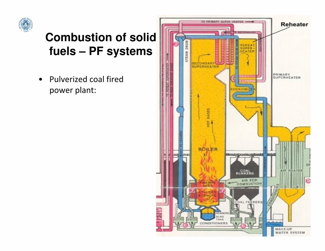
Combustion of solid
fuels – PF systems
• Pulverized coal fired
power plant:

Combustion of solid
fuels – PF systems
• Pulverized coal fired
power plant:

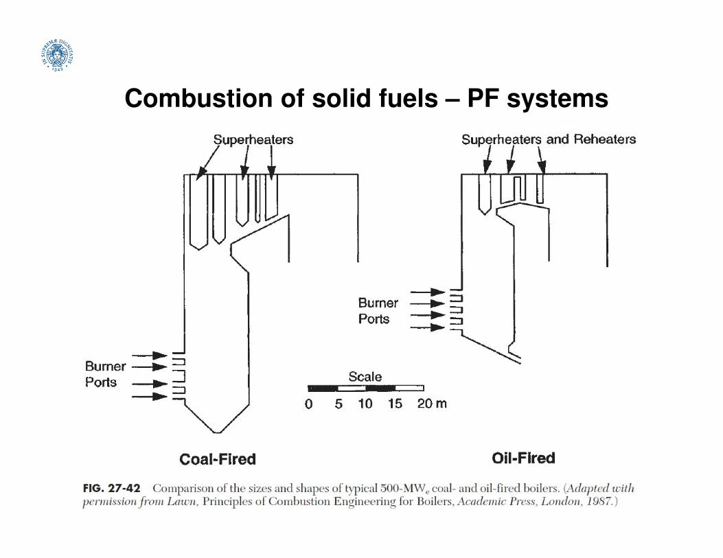
Combustion of solid fuels – PF systems
• Pulverized coal fired power plant:
Combustion of solid fuels – PF systems

Combustion of solid fuels – PF systems
• Pulverized coal fired power plant. Reference data (Spliethoff 2010)
Gross (Net) rated power 740 (690) MW
Efficiency 39%
Capacity 2250 t/hCapacity 2250 t/h
Auxiliary power requirement 50 MW
Mechanical capacity of feed pump 21 MW
Air ratio 1.3
Live steam condition 209 bar, 535°C
Steam generator efficiency 94%
Exhaust steam pressure 0.055 bar

Combustion of solid fuels – PF systems
• Pulverized coal fired power plant:
Different dispositions of
burners for optimizing
temperature fields and
Cross sectional area heat
release rate (MW/m2)
5-6.5 for oil, natural gas
4-5 for hard coal
3-4 for brown coal
Air is used to dry the
coal, transport it
through the
pulverizer, classify it,
and transport it to the
burner. Pneumatic
transport
10-20 m/s
temperature fields and
residence time Volumetric heat release rate
(kW/m3)
220-230 for oil, natural gas
140-160 for hard coal
100-120 for brown coal
Coal particles 10-100 µm
Typical residence time in
the furnace 2-5 s
Combustion of solid fuels – PF systems
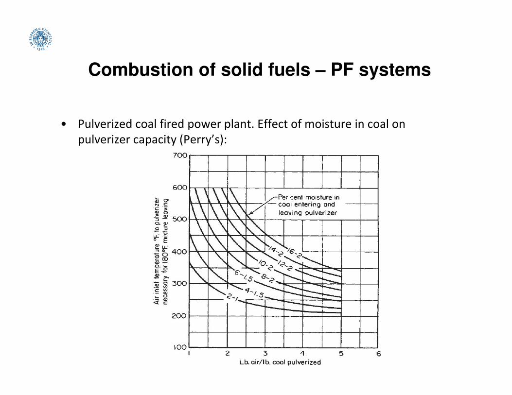
• Pulverized coal fired power plant. Effect of moisture in coal on
pulverizer capacity (Perry’s):

Combustion of solid fuels – PF systems
Fluidynamics and thermal field are mainly
determined by burners configuration and
secondary air velocity.
foulingslagging

Combustion of solid fuels – PF systems
• The purpose of the burner is to produce an adequate flow pattern for
mixing and stable combustion. The injection has impact on the near-
burner area, i.e. on ignition and pollutant formation.
• A substantial fraction of the ignition energy has to be provided by
recirculation of hot flue gas. The ignition can be enhanced by finer
milling and air preheating.milling and air preheating.
• Circular burners are widely used in horizontally fired furnaces and are
capable of firing pulverized coal, oil, and gas.
• Low-NOx burners are designed to delay and control the mixing of
coal and air in the main combustion zone. This combustion approach
can reduce NOx emissions from coal burning by 40 to 50 percent.
• Because of the reduced flame temperature and delayed mixing in a
low-NOx burner, unburned carbon emissions may increase in some
applications and for some coals.

Combustion of solid fuels – PF systems

Combustion of solid fuels – PF systems
Flow and temperature
fields
Tangential firing Opposed firing

Combustion of solid fuels – PF systems
• Pulverized coal fired power plant. Design issues:
- specification of the design fuel and range of fuels fired;
- planned operated regimes (base, mid-range and peak loads);
- legislative directives (e.g. emission limits);- legislative directives (e.g. emission limits);
- efficiency (process complexity, materials, costs);
- instrumentation and control equipment;
- planned lifetime (200’000 h of operation).

Combustion of solid fuels – PF systems
• Pulverized coal fired power plant. Investment costs:
7%
6%Steam generator, gas cleanup
37%
21%
15%
14%
7%
6% cleanup
Turbine, steam cycle
Instrumentation and control
Civil works
Project costs
Mechanical constructions

Combustion of solid fuels – PF systems
• Pulverized coal fired furnace. Design aims:
- stable ignition (furnace section from free expansion of the flame);
- complete burnout (furnace height from char particle residence time);
- prevention of slagging and corrosion inside the furnace (coals with
high slagging tendency will require a larger cross section; it depends
also on the furnace exit temperature FET):
0
20
40
60
80
0 400 800 1200 1600Fu
rna
ce
he
igh
t(m
)
Fuel input (MW)
Burnout limit
FET 1100°C
FET 1230°C

Combustion of solid fuels – PF systems
• Pulverized coal fired furnace. Fouling and slagging zones:

Combustion of solid fuels – PF systems
• Pulverized coal fired furnace. Prevention of fouling and corrosion on
convective heating surfaces:
Presence of Na / K in coal ash and SO3 / HCl in flue gas promotes deposition and
corrosion of the heating surface (formation of alkali sulfates in molten phase
at 600-700°C). Presence (or addition) of Ca / Mg in the fuel reduces corrosion.at 600-700°C). Presence (or addition) of Ca / Mg in the fuel reduces corrosion.
For coals with high slagging tendency, large spacings of steam tubes are chosen.
Depending on the hardness of the deposits and considering the thermal shock of
the boiler material, removal by blowing is possible, using steam, water or air.
Slagging and fouling indexes:
• viscosity temperature (from ash fusion test) problems for T250poise < 1400°C
• basic/acid index B/A=(Fe2O3+CaO+MgO+Na2O+K2O)/(SiO2+Al2O3+TiO2)
problems for B/A > 0.5
• slagging index RS = B/A * S (S sulfur) problems for RS > 0.6

Combustion of solid fuels
Cyclone furnaces
• In cyclone firing the coal is not pulverized but is crushed to 4-mesh
(4.76-mm) size and admitted tangentially with primary air to a
horizontal cylindrical chamber, called a cyclone furnace, which is
connected peripherally to a boiler furnace.
• Secondary air is admitted tangentially , so that almost all of the coal
burns within the chamber. The combustion gas then flows into theburns within the chamber. The combustion gas then flows into the
boiler furnace.
• In the cyclone furnace, finer coal particles burn in suspension and the
coarser ones are thrown centrifugally to the chamber wall, where
most of them are captured in a sticky wall coating of molten slag. The
slag drains continuously into the boiler furnace and thence into a
quenching tank.
• A typical firing rate is about 18.6 GJ/(h×m3).
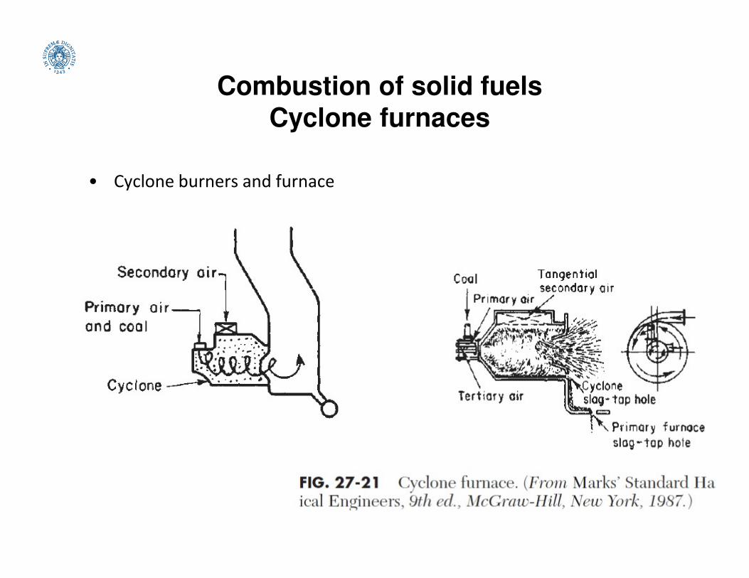
Combustion of solid fuels
Cyclone furnaces
• Cyclone burners and furnace

Combustion of solid fuels
Biomass furnaces
• Biomass combustion is mainly used for heat production in small
/ medium scale units such as wood stoves, log wood boilers,
pellet burners, wood chip furnaces, straw-fired furnaces.
• District heating systems are often in the size range from 0.5 to
5 MWth with some applications up to 50 MWth.5 MWth with some applications up to 50 MWth.
• CHP production with biomass is applied by:
– steam cycles (Rankine cycle) with steam turbines and steam engines,
– organic Rankine cycles (ORC) with power outputs of 0.5 - 10 Mwe,
– Stirling engines (10 kWe to 100 kWe) and EFMGT systems.
• Co-firing in fossil-fired power stations enables the advantages
of large size plants (>100 MWe), which are not applicable for
dedicated biomass combustion due to limited local biomass
availability.
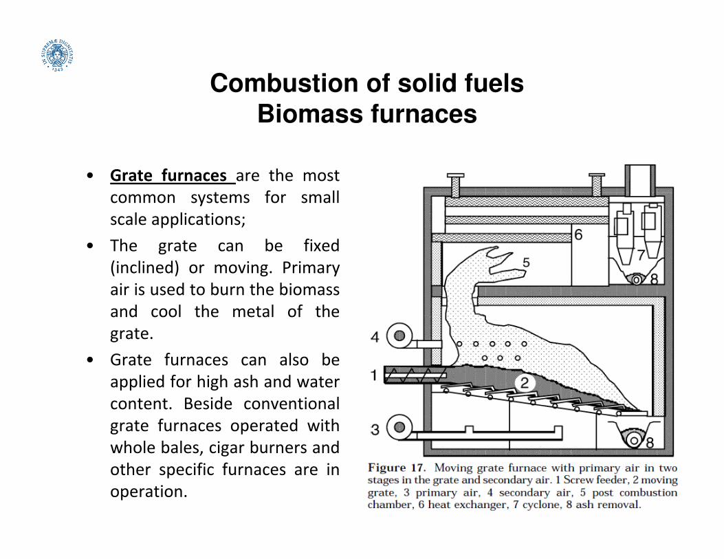
Combustion of solid fuels
Biomass furnaces
• Grate furnaces are the most
common systems for small
scale applications;
• The grate can be fixed
(inclined) or moving. Primary
air is used to burn the biomassair is used to burn the biomass
and cool the metal of the
grate.
• Grate furnaces can also be
applied for high ash and water
content. Beside conventional
grate furnaces operated with
whole bales, cigar burners and
other specific furnaces are in
operation.
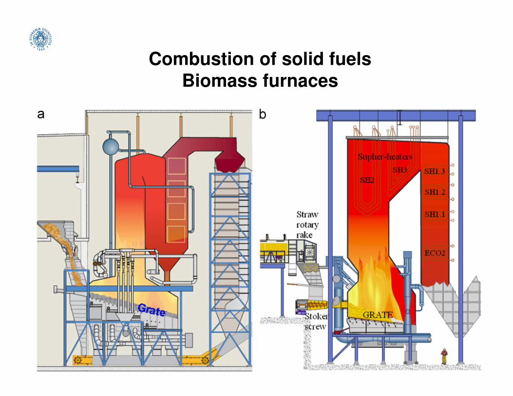
Combustion of solid fuels
Biomass furnaces
Combustion of solid fuels
Biomass furnaces
• Efforts in the area of grate-firing of biomass:
• Pollutant emissions: The incomplete combustion gives rise to higher
emissions of CO, hydrocarbons (CxHy), tar, poly aromatic hydrocarbons
(PAH) and incompletely burned char from biomass combustion in grate-
fired boilers. Concerns for high Cl and N content of some biomass.
• Deposit formation and corrosion: Grate-firing of some biomass fuels with a• Deposit formation and corrosion: Grate-firing of some biomass fuels with a
high Cl content (e.g. straw) and alkali compounds may suffer from severe
deposition and corrosion problems. Deposits reduce both the heat transfer
ability of combustor surfaces and the overall process efficiency, while
corrosion reduces the lifetime of the equipment. Deposition and corrosion
depend not only on fuel properties but also on combustion environments
(e.g., atmosphere, temperatures, and mixing).
• Experimental and modelling studies: experimental investigation provides
combustion related data for model validation. Modelling of biomass
conversion in the fuel bed should be coupled with computational fluid
dynamics (CFD) simulations, for modellig the mixing, combustion, and
pollutant formation.
Combustion of solid fuels
Biomass furnaces
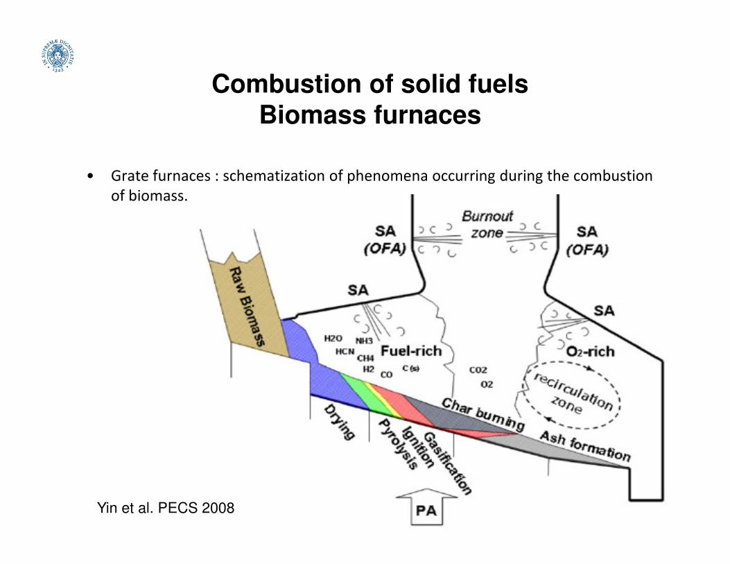
• Grate furnaces : schematization of phenomena occurring during the combustion
of biomass.
Yin et al. PECS 2008
Combustion of solid fuels
Biomass furnaces
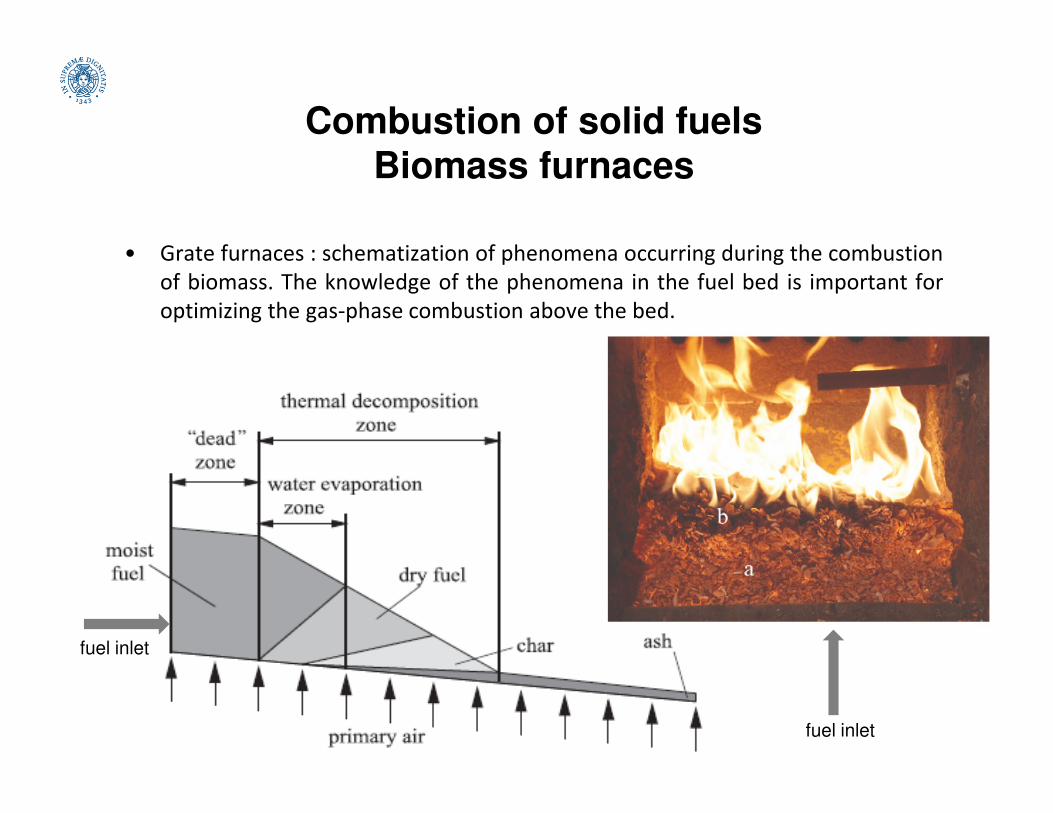
• Grate furnaces : schematization of phenomena occurring during the combustion
of biomass. The knowledge of the phenomena in the fuel bed is important for
optimizing the gas-phase combustion above the bed.
fuel inlet
fuel inlet

Combustion of solid fuels
Biomass furnaces
• Grate furnaces: schematization of phenomena occurring during the
combustion of biomass. The releases of volatiles affects the heat output
from the grate area and the stability of combustion. The flame propagation
also plays an important role in the release of NOx precursors, particulate
matter formation precursors, and other pollutant formation precursors.
Combustion of solid fuels
Biomass furnaces
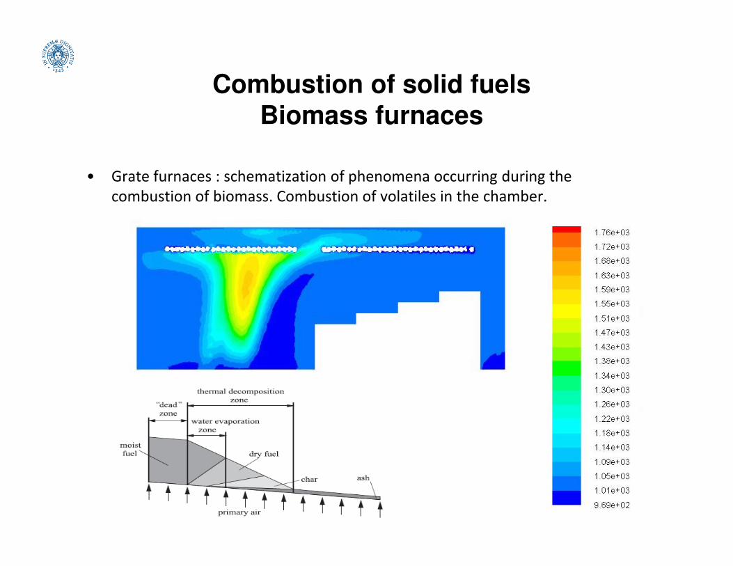
• Grate furnaces : schematization of phenomena occurring during the
combustion of biomass. Combustion of volatiles in the chamber.
Combustion of solid fuels
Biomass furnaces
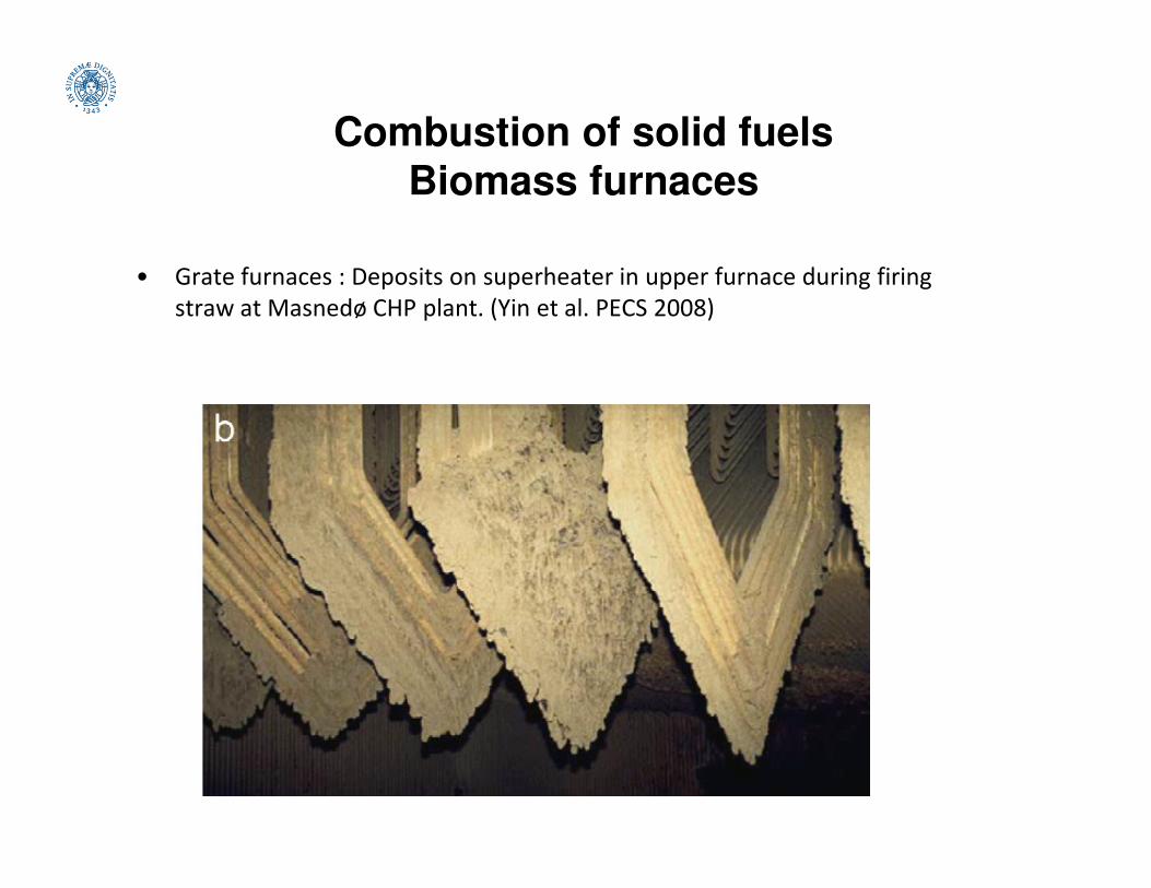
• Grate furnaces : Deposits on superheater in upper furnace during firing
straw at Masnedø CHP plant. (Yin et al. PECS 2008)
Combustion of solid fuels
Biomass furnaces
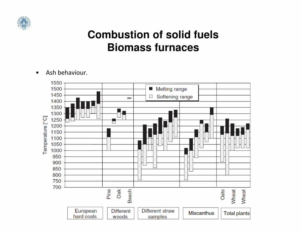
• Ash behaviour.
Combustion of solid fuels
Biomass furnaces
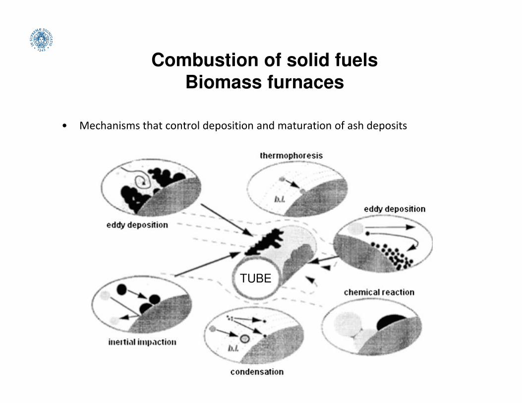
• Mechanisms that control deposition and maturation of ash deposits
TUBE

Combustion of solid fuels
Biomass furnaces
• Relationship between the deposit viscosity and the deposit strength. Cases
are ordered in the sequence of decreasing viscosity
Combustion of solid fuels
Biomass furnaces
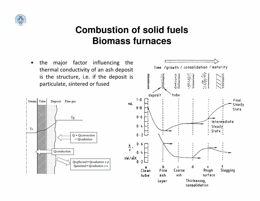
• the major factor influencing the
thermal conductivity of an ash deposit
is the structure, i.e. if the deposit is
particulate, sintered or fused

Combustion of solid fuels
Biomass furnaces
• Grate furnaces : Mechanisms of deposit formation and corrosion of tubes.
The volatile alkali inorganic vapours and fine particles may contribute to
the initial deposit formation while the inert non-volatile ash particles
contribute to the build-up of the deposit.
Combustion of solid fuels
Biomass furnaces
• Possible solutions to the problems of deposition and high temperature
corrosion during biomass combustion:
Use of additives, to raise the melting temperatures of the ash formed
during biomass combustion, or to prevent the release of gaseous KCl, or
react with KCl to form less corrosive components, or to combine thereact with KCl to form less corrosive components, or to combine the
effects. Examples: Al2O3, CaO, MgO, CaCO3 MgCO3 and kaolin. Also
aqueous solution of ammonium sulphate sprayed in the combustion zone.
Cofiring with coal, peat or sludge.
Use of new alloys or new forms of ceramic composite coating (for
mitigating corrosion).
Reduction of surface temperatures of super-heaters.

Combustion of solid fuels
Biomass furnaces
• Cigar burner for bales (straws from agricultural residues). A piston
pushes the bale inside a feeding tunnel, in which the biomass
devolatilizes. The oxidation of the charrified material in the combustion
chamber occurs at 900°C (to avoid deposition of low melting ash).

Combustion of solid fuels
Biomass furnaces
• Underfeed rotating grates. The grate is coned shaped. The rotation
increase the mix of the biomass. Primary air is fed just above the
biomass bed.

Combustion of solid fuels
Biomass furnaces
• To achieve complete burnout and high efficiencies in small scale combustion,
downdraft boilers with inverse flow have been introduced.

Combustion of solid fuels
Biomass furnaces
• Understoker furnaces are
mostly used for wood
chips and similar fuel with
relatively low ash content.
Special types of furnaces
have been developed forhave been developed for
straw that has very low
density and is usually
stored in bales.
Combustion of solid fuels
Biomass furnaces
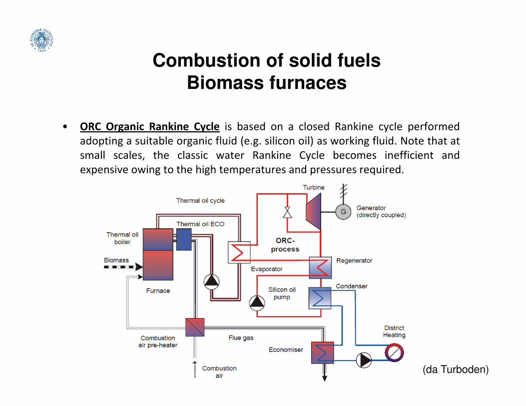
• ORC Organic Rankine Cycle is based on a closed Rankine cycle performed
adopting a suitable organic fluid (e.g. silicon oil) as working fluid. Note that at
small scales, the classic water Rankine Cycle becomes inefficient and
expensive owing to the high temperatures and pressures required.
(da Turboden)

Combustion of solid fuels
Biomass furnaces
• ORC cycle: energy balance.

Combustion of solid fuels
Biomass furnaces
• EFMGT (Externally Fired Micro Gas Turbine) cycle is based on a Brayton
cycle. The combustion air is used as working fluid.

Combustion of solid fuels
Biomass furnaces
Main application: decentralized heat and power generation (0.1-1 MW)
ORC cycle (PROS)
• low mechanical stress and high turbine
efficiency;
• long operational life (no erosion/corrosion);
• no water treatment system required;
EFMGT cycle (PROS)
• completely automatic plant;
• versatility on feedstock;
• no auxiliary fuel need;
• no pressurized/dangerous fluids used;
Specific biomassconsumption
(kg/kWhe)
Electricalefficiency
(%)
Heat topowerratio
Available HeatTemperature
(°C)
Specific cost(€/kWe)
ORC 2.5-3.5 11-13 5:1 40-80 5-7’000
EFMGT 2.5-4 9-12 3:1 40-80 7-8’000
RSE (Steam engine) 4-5 8-9 6:1 100-150 5-6’000
SE (Stirling) 3.5-4 8-10 5:1 60-85 6-8’000
Gasification ICE 1.2-1.7 25 1.5-2:1 70-80 / 500 4-5’000
• no water treatment system required;
• good partial load performance .
• no pressurized/dangerous fluids used;
Fluidized beds
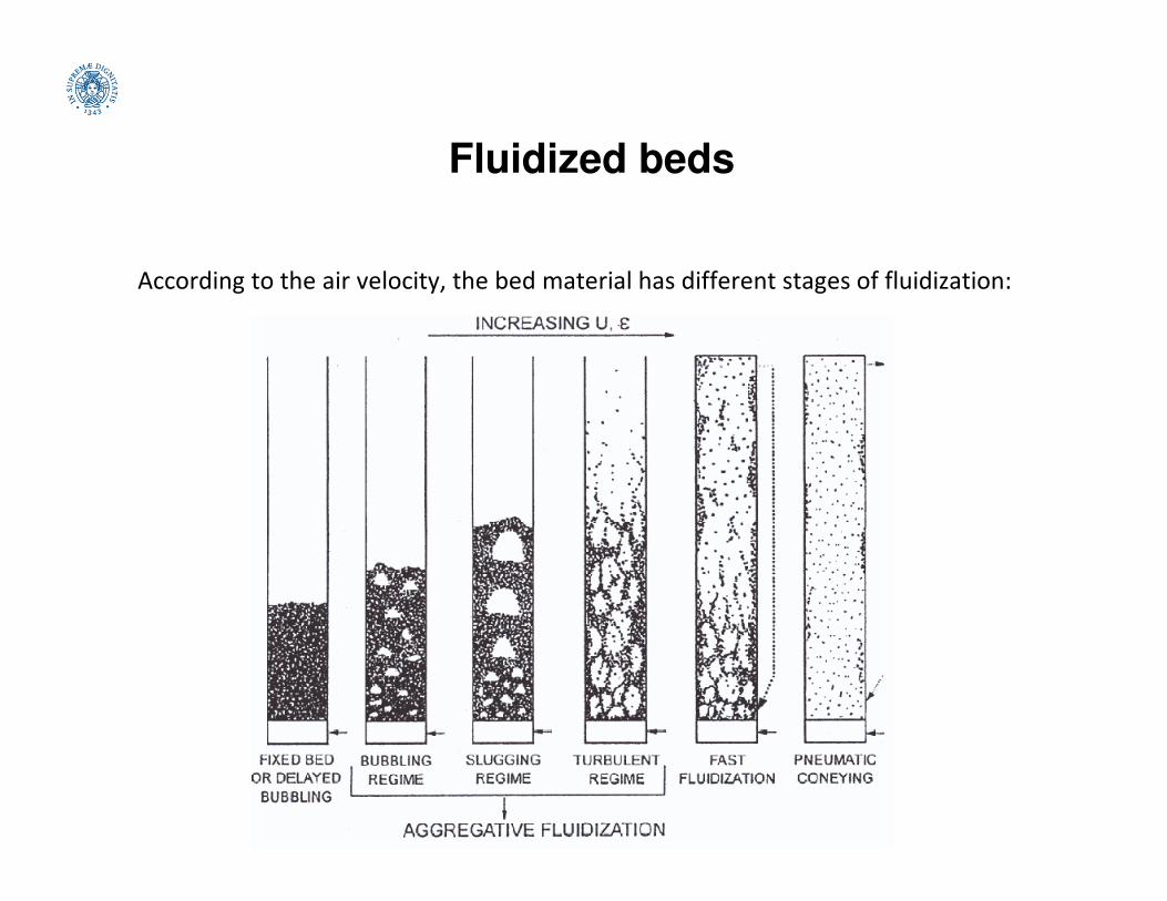
According to the air velocity, the bed material has different stages of fluidization:

Fluidized beds
According to the air velocity, the bed material has different stages of fluidization:

Fluidized beds
According to the air velocity, the bed material has different stages of fluidization:

Fluidized beds
• A fixed or packed bed refers to a bed of stationary particles residing on a
perforated grid, through which a gas flows. The gas exerts a drag force on
the particles, causing a pressure drop across the bed. The pressure drop per
unit height of a packed bed, ∆P/L, of uniformly sized particles, dp is
correlated as (Kozeny-Carman, 1927-37):
where, ε is the void fraction in the bed, φ is the sphericity of bed solids, µ is the
dynamic viscosity, and ρg is the density of the gas. The superficial gas
velocity, U is defined as the gas flow rate per unit cross section of the bed.
180180

Fluidized beds
• If the gas-flow rate through the fixed bed is increased, the pressure drop due
to the fluid drag continues to rise, until the superficial gas velocity reaches a
critical value known as the minimum fluidization velocity, Umf. At the
velocity where the fluid drag is equal to a particle’s weight less its buoyancy,
the fixed bed transforms into an incipiently fluidized bed. Since the pressure
drop across the bed equals the weight of the bed, the fluid drag FD is writtendrop across the bed equals the weight of the bed, the fluid drag FD is written
as:
where A and L are the cross-sectional area and height of the bed, respectively.
The minimum fluid velocity at which the bed just becomes fluidized (Umf)
may be obtained by:
The values of the empirical constants C1 and C2 as taken from experiments are
27.2 and 0.0408, respectively (Grace, 1982).

Fluidized beds
According to the air velocity, the bed material has different stages of fluidization:
fixed bed fluid bed
Bed expansion (H bed
height, ε voidage)

Fluidized beds
• A fluidized bed demonstrates all the characteristics of a fluid.
• The static pressure at any height is approximately equal to the weight of the
bed solids per unit of cross-sectional area above that level.
• Particles are well mixed, and the bed maintains a nearly uniform
temperature throughout its body when heated.
Fluidized beds
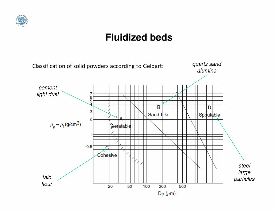
Classification of solid powders according to Geldart:
cement
light dust
quartz sand
alumina
talc
flour
steel
large
particles

Fluidized beds
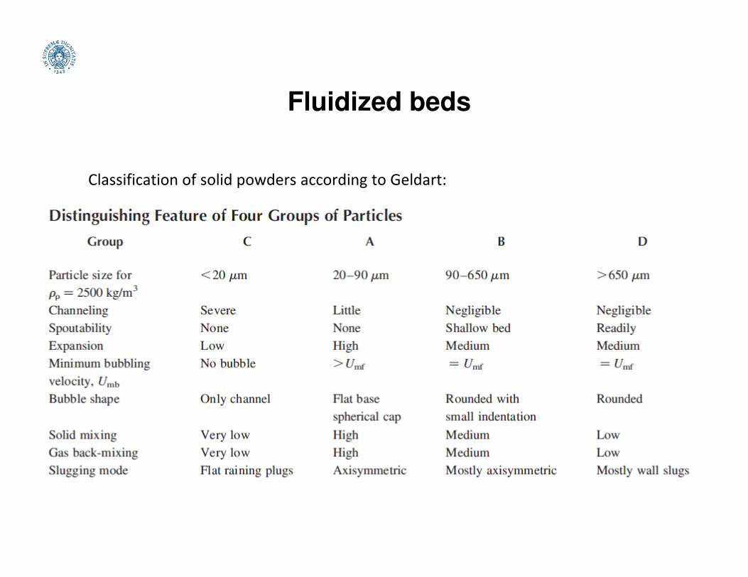
Classification of solid powders according to Geldart:
• GROUP A. These particles are typically in the range of 30 to 100 µm (for
ρ=2500 kg/m3). These particles fluidize well, but expand considerably after
exceeding the minimum fluidization velocity and before bubbles start
appearing. Many circulating fluidized bed systems use Group A particles.
• GROUP B. These particles are normally in the range of 100 to 500 µm (for• GROUP B. These particles are normally in the range of 100 to 500 µm (for
ρ=2500 kg/m3). They fluidize well, and bubbles appear as soon as the
minimum fluidization velocity is exceeded. The majority of the fluidized bed
boilers use this group of particles.
• GROUP C. These particles are very fine and are typically smaller than 30 µm
(for ρ=2500 kg/m3). The interparticle forces are comparable to the
gravitational force on these particles. So, these particles are very difficult to
fluidize. An attempt at fluidization often results in channelling.
• GROUP D. These are the coarsest of all particles (>500 µm) (for ρ=2500
kg/m3). They require a high velocity to fluidize these solids. Spouted beds
and some bubbling fluidized bed boilers can operate on this size of solids.
Fluidized beds
Classification of solid powders according to Geldart:

Combustion of solid fuels – Fluidized beds
Classification of solids according to Geldart:
Fluidized beds
• For Group B and D particles, a further increase in gas flow besides the
minimum fluidization can cause the excess gas to flow in the form of
bubbles. The gas–solid suspension around the bubbles and elsewhere in the
bed is called the emulsion phase. The superficial gas velocity through this
phase is of the order of Umf and it has a characteristic voidage εmf.
• A fluidized bed of Group A particles does not start bubbling as soon as the• A fluidized bed of Group A particles does not start bubbling as soon as the
superficial velocity exceeds Umf, but instead the bed starts expanding. The
bubbles start appearing when the superficial gas velocity exceeds another
characteristic value called minimum bubbling velocity (Umb).
• Bubbles are essentially gas voids with little or no solids. Due to the buoyancy
force, bubbles would rise through the emulsion phase, by-passing the
particles. The bubble size increases with particle diameter, excess gas
velocity, (U - Umf), and with its distance above the distributor or grid of the
bed. The bubbles can coalesce and grow only to a maximum size, beyond
which they collapse.

Fluidized beds
• The bubbles erupt on the surface of a bubbling bed ejecting solids which
travel up through the freeboard. The solid concentration reduces along the
height but remains unchanged beyond the TDH.

Fluidized beds
• The air distribution grate supports the bed materials and homogeneously
distributes the fluidizing gas into the bed of solids.
• Nonuniform distribution of air may result in erosion, plugging, back-sifting, and
collapse of the bed due to agglomeration.

Fluidized beds
• The function of the air box is to distribute the air under the grid as uniformly
as possible.
Air plenum with side-entry air Flow-straightening vanes can help uniform
distribution of air in the plenum chamber

Fluidized beds
• A bubbling fluidized bed boiler would normally have an open space above its
bed surface, known as freeboard. Each bubble carries some solids upwards
in its wake. Bubbles erupt at the surface of the bed, throwing or entraining
particles into the freeboard above. Due to their momentum and local gas
drag, the entrained particles travel upwards through the freeboard.
• Since the fluid drag is not necessarily greater than the weight of all particles• Since the fluid drag is not necessarily greater than the weight of all particles
or groups of particles, some of the particles may disengage from the gas in
the freeboard, returning to the dense bed due to gravitational force. This
process of disengagement reduces the upward flux of particles exponentially
along the height of the freeboard.
• Beyond a certain height, only a negligible amount of particles disengage from
the gas to return to the dense bed. This height is known as transport
disengaging height (TDH). Beyond this height, only particles whose weight is
sufficiently small to be balanced by the fluid drag are carried up. More
specifically, particles with terminal velocities lower than the superficial
velocity in the freeboard are carried away (elutriation).

Fluidized beds
• An important consideration is to minimize the entrainment of unburnt
carbon by choosing a freeboard exceeding or close to the transport
disengaging height (TDH). Estimating TDH:

Fluidized beds
• Bubbles are likely to have a limited exchange of gas with the emulsion phase.
Burning fuel particles, requiring oxygen, generally reside in the emulsion
phase. In the absence of efficient gas exchange between the two phases,
there is major bypassing of oxygen.
• Some mixing of the oxygen from the bubble and emulsion phases occurs in
the splash zone immediately above the bed surface. Fine particles couldthe splash zone immediately above the bed surface. Fine particles could
receive the oxygen here and continue to burn in the freeboard.
• The amount of gas passing through the emulsion phase is equal to that
required for minimum fluidization, AUmf. Therefore, the remaining gas, A(U-
Umf) passes through the bubble phase. The equivalent volume diameter db,
of a bubble at a height Z, above the distributor is a function of the nozzle
area of the distributor A0, and the superficial gas velocity through the bubble
phase. It can be estimated by (Darton 1977):

Combustion of solid fuels – Fluidized beds
• Exchange between bubble and emulsion phases:
SAND PARTICLESSAND PARTICLES

Combustion of solid fuels – Fluidized beds
Modelling a fluidized bed:
FREEBOARD
exit
PF
R
SPLASHING REGION
Gas inlet
Fuel feeding
dense
phase
bubble
phase
CSTR
PF
R
CSTR
BED REGION

Fluidized beds
• BUBBLING TO TURBULENT TRANSITION
The pressure drop across a turbulent bed fluctuates rapidly. As the velocity is
increased, the amplitude of fluctuation increases, reaching a peak at the
velocity uc. It then reduces to a steady value as the fluidizing velocity is
increased further to the velocity uk. The transition from a bubbling to
turbulent bed does not take place sharply at one velocity.turbulent bed does not take place sharply at one velocity.
The gas–solid contact in this regime is good and the reactor performance
approaches that of an ideal back-mix reactor. Heat transfer coefficients in
turbulent regimes are lower than those in the bubbling bed regime, but that
is due to the lower solid concentration in a turbulent bed.
There is no well-established correlation for calculating the velocity of transition
from the bubbling to turbulent bed. However, some correlations (Grace,
1982) based on small-diameter beds (with ρpdp in the range 0.05 to 0.7
kg/m2) are:

Fluidized beds
• TERMINAL VELOCITY OF A PARTICLE
Consider a particle falling freely from rest and accelerating under gravity in an
infinite and stationary medium. The buoyancy force and the fluid drag
oppose the effect of gravity. The particle accelerates until it reaches an
equilibrium velocity called the terminal velocity.
The drag force on the particle is related to the kinetic energy of the fluid and theThe drag force on the particle is related to the kinetic energy of the fluid and the
projected area of the particle, and is defined as:

Fluidized beds
• TERMINAL VELOCITY OF A PARTICLE
If both the gas and particle move upwards with velocities U and Us, respectively,
the particle will experience a fluid drag due to the relative velocity (U – Us)
resisting its fall. Thus, the force balance under steady state can be written as:
Gravitational force = Buoyancy force + Drag forceGravitational force = Buoyancy force + Drag force
The velocity of the particle when the gas velocity U is zero, is known as the
terminal velocity, Ut. The terminal velocity is essentially the slip velocity
between the fluid and particle in a pneumatic transport. For spherical
particles:

Fluidized beds
• FAST FLUIDIZED BED (CIRCULATING BEDS)
In the context of its use in Circulating
fluidized bed (CFB) boilers, the fast
fluidized bed may be defined as a high
velocity gas–solid suspension where
particles, elutriated by the fluidizing gas
RISER
particles, elutriated by the fluidizing gas
above the terminal velocity of individual
particles, are recovered and returned to
the base of the furnace at a rate
sufficiently high to cause a degree of solid
refluxing that will ensure a minimum
level of temperature uniformity in the
furnace.
The furnace of a typical circulating fluidized
bed operates in a regime lying between
turbulent fluidization and pneumatic
transport.
A fast fluidized bed is comprised of solid
agglomerates moving up and down in a very dilute
dispersion of solids.
(P. Basu 2006)
DOWN COMER

Combustion of solid fuels – Fluidized beds
• In fluidized-bed combustion (FBC) fuel is burned in a bed of particles
supported in an agitated state by an upward flow of air introduced via an air
distributor. The bed particles may be sand or ash derived from the fuel, but
usually they are a sulfur sorbent, like limestone or dolomite.
• Fluidized beds have inherently good heat-transfer characteristics, and these
ensure even temperatures within the combustor and high flux rates toensure even temperatures within the combustor and high flux rates to
steam/water cooling circuits.
• The good gas-solids contacting promotes effective sulfur capture and allows
high combustion efficiency to be achieved at temperatures significantly lower
than those of a pulverized coal furnace (typically 1116 K compared to over
1589 K).
• These lower temperatures also result in reduced slagging and fouling
problems and significantly lower NOx formation. This latter benefit, in
conjunction with the reduced SO2 emissions, constitutes one of the great
advantages of fluidized-bed combustors: in situ pollution control.

Combustion of solid fuels – Fluidized beds
• There are two types of FBC unit distinguished by their operating flow
characteristics: bubbling and circulating. These two types operate at
atmospheric pressure, AFBC, or at elevated pressure, PFBC.
• Pressures for PFBC are in the range 0.6 to 1.6 MPa (90 to 240 psia).
• Typical superficial fluidizing velocities are tabulated as follows.
Atmospheric Pressurized
Bubbling 1.5–2.7 m/s 1–1.2 m/s
Circulating 3.7–7.3 m/s 3.7–4.3 m/s

Combustion of solid fuels – Fluidized beds
• Stationary or bubbling fluidized
bed (SFB) as well as circulating
fluidized bed (CFB) boilers are
applied for large-scale
applications and often used for
waste wood or mixtures ofwaste wood or mixtures of
wood and industrial wastes, e.g.,
from the pulp and paper
industry

Combustion of solid fuels – Fluidized beds
• COMBUSTION IN BUBBLING BEDS
In bubbling beds a large proportion of the noncombustible feedstock, mainly
sorbent derived, remains in the combustor, forming the bed. Bed depth is
maintained by draining off excess material. Most of the gas in excess of that
required for minimum fluidization appears as bubbles (voids), and these carry
particles upward in their wake, promoting the rapid vertical mixing within theparticles upward in their wake, promoting the rapid vertical mixing within the
bed that results in the even temperatures characteristic of FBC units.
Bed temperature is controlled by heat transfer to in-bed boiler tubes and/or to
the water-wall tubes used to enclose the furnace. Some units have
experienced metal loss from these tube surfaces, a combined effect of erosion
and abrasion, and suitable protection needs to be provided. Protective
measures include surface coatings such as plasma-sprayed metal coatings
incorporating silicon carbide, and metal fins to disrupt the solids-flow pattern.
The particulates leaving the boiler with the flue gas consist of unreacted and
spent sorbent, unburned carbon, and ash. Multiclones after the convection
pass remove much of the particulate matter and recycle it to the combustor,
increasing the in-furnace residence time and improving combustion efficiency.

Combustion of solid fuels – Fluidized beds
• COMBUSTION IN CIRCULATING BEDS
CFBs operate at higher velocities, and virtually all the solids are elutriated from
the furnace. The majority of the elutriated solids, still at combustion
temperature, are captured by reverse-flow cyclone(s) and recirculated to the
foot of the combustor.
The foot of the combustor is a potentially very erosive region, as it contains largeThe foot of the combustor is a potentially very erosive region, as it contains large
particles not elutriated from the bed, and they are being fluidized at high
velocity. Consequently, the lower reaches of the combustor do not contain
heat-transfer tubes and the water walls are protected with refractory.
The furnace temperature is controlled by heat transfer through the exposed
upper water-wall tubes. As the units increase in size, more heat-transfer
surface is required than is provided by the walls.

Combustion of solid fuels – Fluidized beds
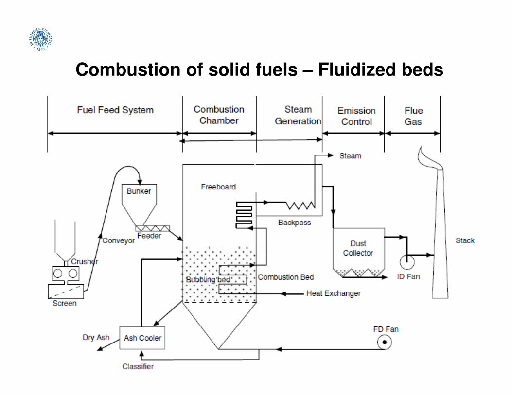
• Typical fluidized bed boiler plant firing solid fuels
Combustion of solid fuels – Fluidized beds

• 110 MWe CFB boiler
Combustion of
solid fuels –
Fluidized beds
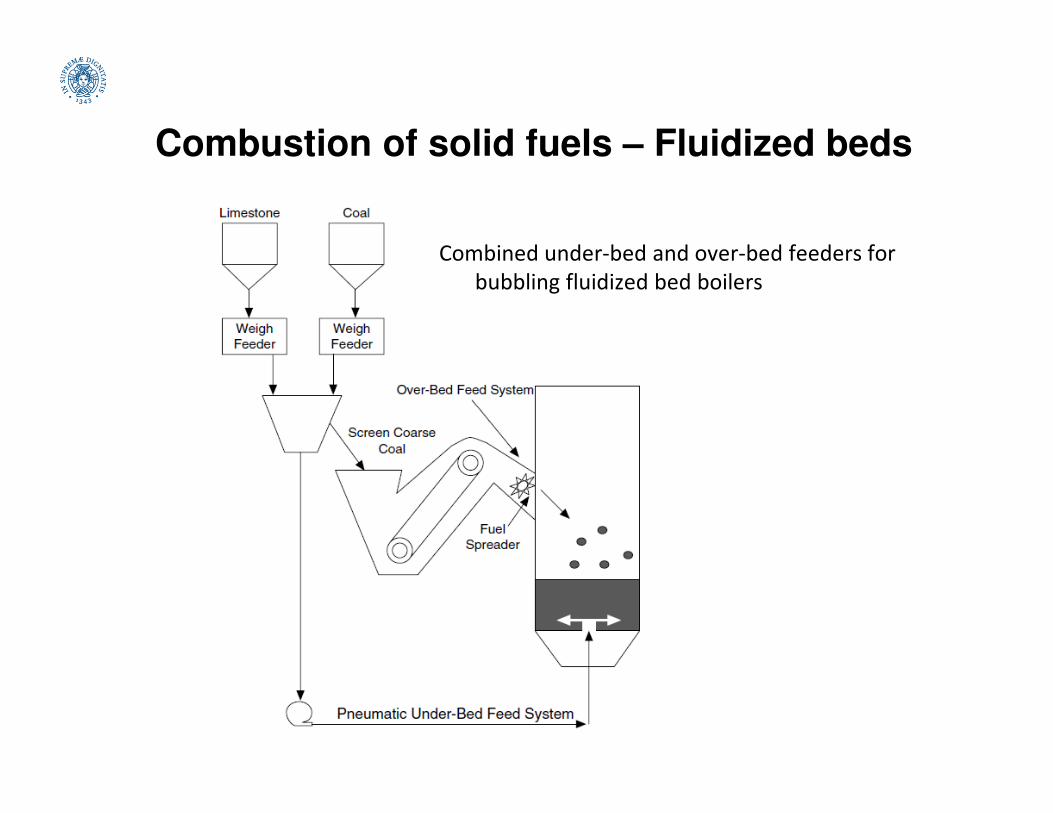
Combustion of solid fuels – Fluidized beds
Combined under-bed and over-bed feeders for
bubbling fluidized bed boilers

Combustion of solid fuels – Fluidized beds
Simplified flow diagram for atmospheric circulating fluidized bed combustor
(with external heat exchanger)
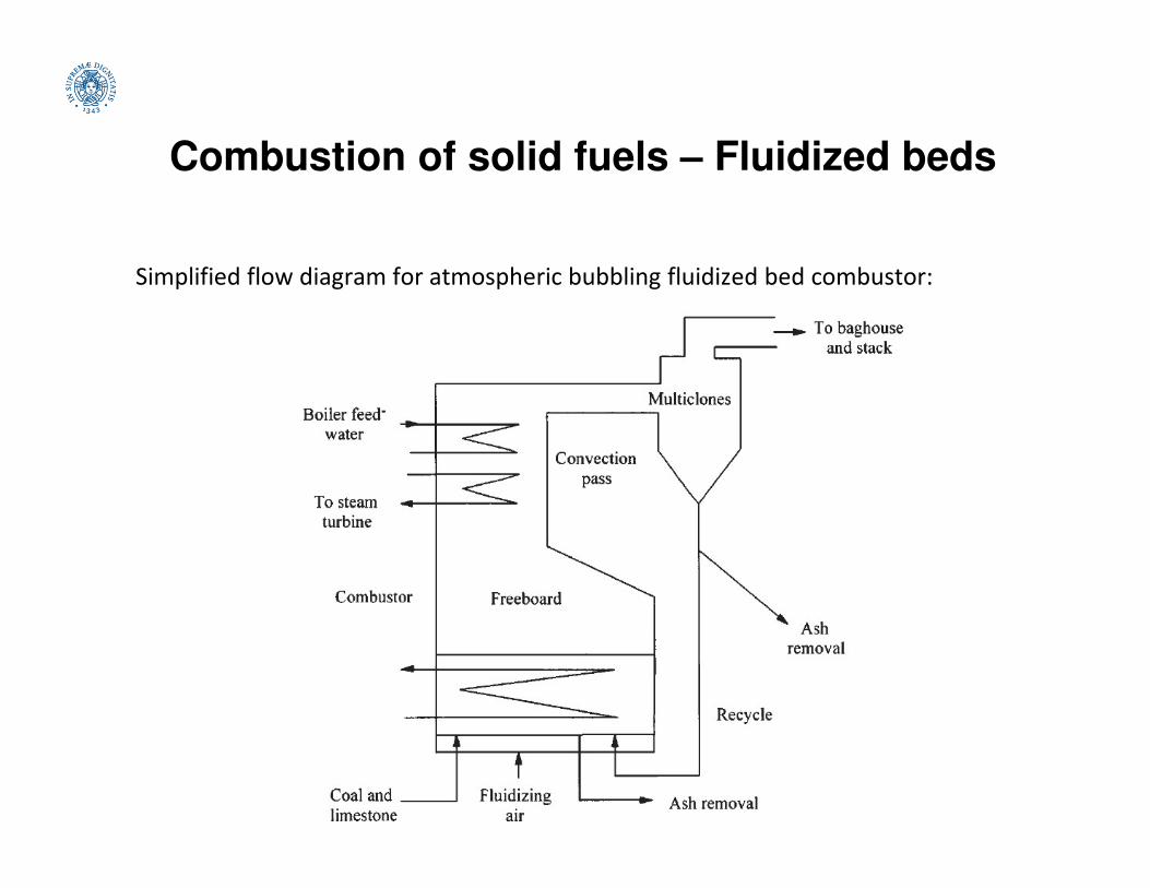
Combustion of solid fuels – Fluidized beds
Simplified flow diagram for atmospheric bubbling fluidized bed combustor:

Combustion of solid fuels – Fluidized beds
Particle temperature and main phenomena of combustion in fluidized bed:
Combustion of solid fuels – Fluidized beds
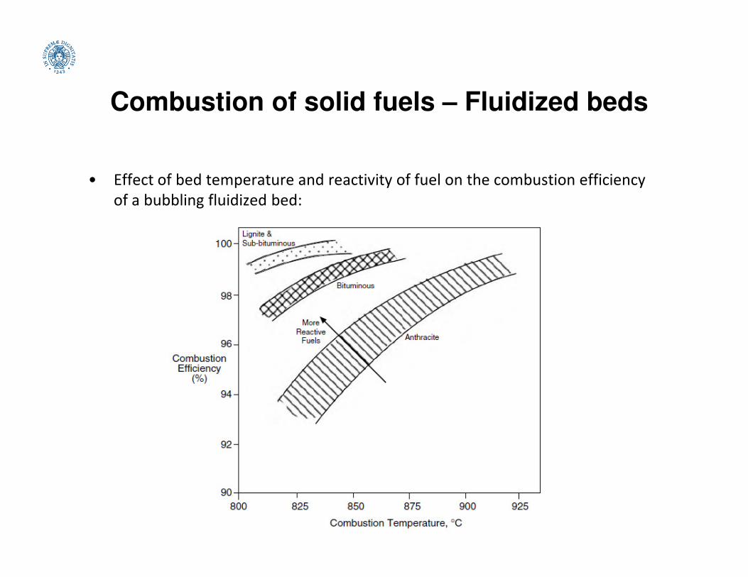
• Effect of bed temperature and reactivity of fuel on the combustion efficiency
of a bubbling fluidized bed:

Combustion of solid fuels – Fluidized beds
• Corrosion and erosion could take place simultaneously in some places.
• Part of the ash deposited inside the furnace can melt and cause slagging. If the
ash is deposited in the gas duct downstream of the furnace, the phenomenon
is called fouling, which does not involve melting of the ash.

Combustion of solid fuels – Fluidized beds
• Although the bed material (sand, silicon dioxide) melts at 1450°C, the eutectic
mixture with sodium formed melts at 874°C. For potassium salt, the eutectic
mixture will melt at 754°C. This makes the particle surface sticky disturbing the
fluidization and generating local hot spots. Hot spots lead to agglomeration
and sintering. Bed agglomeration (clinkering) leads to particle growth and
hence alters the size distribution of particles in the beds.hence alters the size distribution of particles in the beds.
single sandparticle
agglomerate formation-
bindingmaterial rich
inpotassium

Combustion of solid fuels – Fluidized beds
• The fifteen largest Bubbling fluidized bed boilers that fire biomass (BFB)
Feedstock origin: L (Local), I (Import), M (Mixed), ? (Not known). IEA 2013
Combustion of solid fuels – Fluidized beds
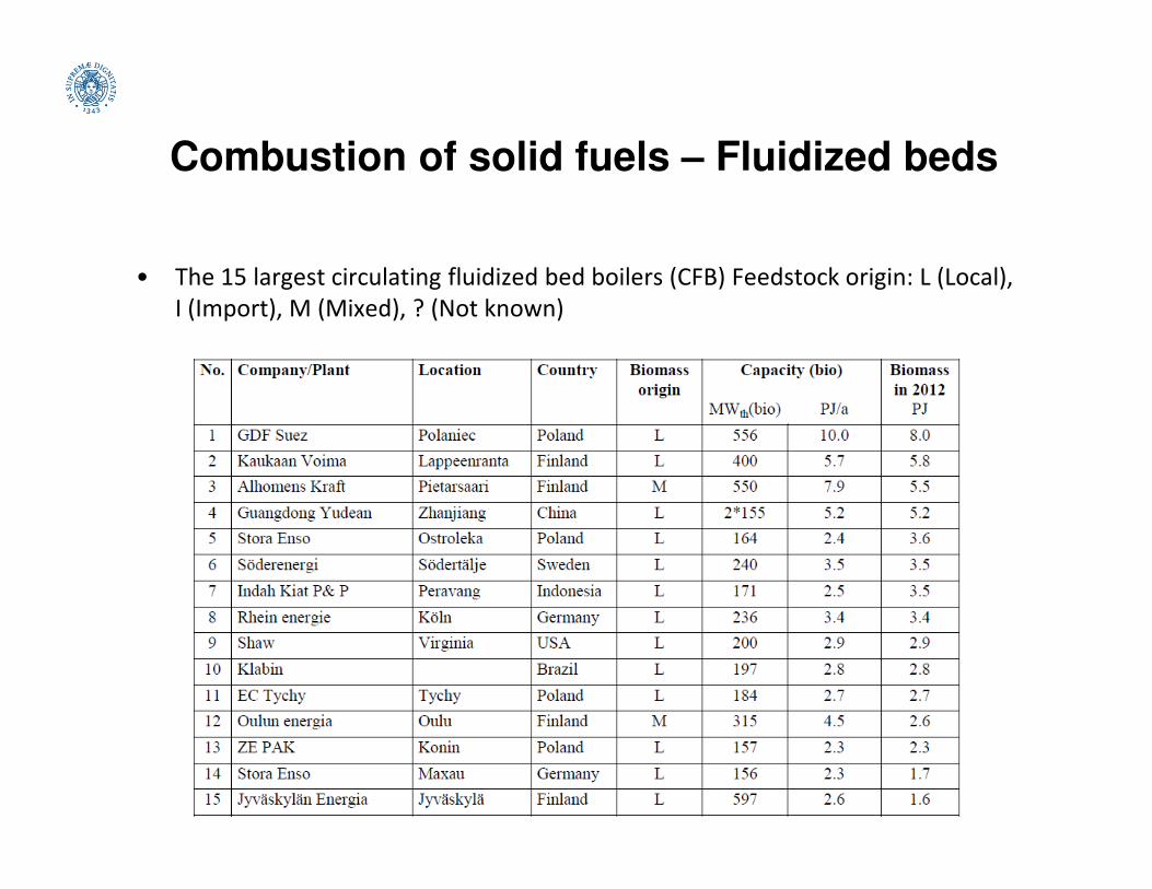
• The 15 largest circulating fluidized bed boilers (CFB) Feedstock origin: L (Local),
I (Import), M (Mixed), ? (Not known)

Combustion of solid fuels
Grates Bubbling (BFB) and circulating
(CFB) fluidized beds
Pulverized fuel (PF)
firing systems
Advantages:-Relatively minor fuelrequirement-Clear design-Simple operation-Low auxiliary power demand
Advantages:-Flue gas cleaning can consist only in particulate removal
Disadvantages:-Complex operation
Advantages:-Large capacities-High power density-Good burnout-Utilizable ash
-Low auxiliary power demand-Relatively low NOx emissions-Partial desulfurization bylimestone addition
Disadvantages:-High UBC (2-4%)-High flue gas temperaturesdue to limited air preheating-Unsuitable for fine grainedfuels
-Complex operation-High thermal inertia-High limestone demand for sulfur capture-Ash not utilizable without treatment
Advantages of CFB against BFB:-Better burnout-Lower limestone demand for sulfur capture-Lower emission values-No in-bed heating surfaces at risk of erosion-Better power control
Disadvantages:-Relatively major fuelpreparation requirement-Complex operation-Flue gas cleaning neededfor particulates, SO2 and NOx.

Combustion of solid fuels
Co-combustion
• Co-combustion of biomass with coal leads to a substitution of
fossil fuels and to a net reduction of CO2 emissions.
• A co-utilization of biomass with other fuels can be
advantageous with regard to cost, efficiency, and emissions.
Lower specific cost and higher efficiencies of large plants can beLower specific cost and higher efficiencies of large plants can be
utilized for biomass and emissions of SOX and NOX can be
reduced by co-firing.
• Attention must be paid to increased deposit formation in the
boiler and limitations in ash utilization due to constituents in
biomass, especially alkali metals and chlorine.
• The share of biomass is usually limited to approximately 5-10%
of the fuel input.

Co-combustion
• Three options for co-utilization of biomass with coal:
– (a) Co-combustion or direct co-firing (most common option): The
biomass is directly fed to the boiler furnace (fluidized bed, grate,
or pulverized combustion), if needed after physical preprocessing
of the biomass such as drying, grinding, or metal removal. For low
cofiring levels (5-8%), biomass can be combined with coal prior to
the pulverizers. For moderate (8-15%) levels, a separate biomass
preparation and delivery system should be provided. For higher
levels, a fluidized bed could be used.
– (b) Indirect co-firing: The biomass is gasified and the product gas
is fed to a boiler furnace (thus a combination of gasification and
combustion).
– (c) Parallel combustion: The biomass is burnt in a separate boiler
for steam generation. The steam is used in a power plant together
with the main fuel.

Co-combustion
• Effects of Co-combustion on plant operation.
• Negative effects of co-firing are:
– additional investment cost for biomass pretreatment and boiler
retrofitting,
– higher operation cost due to increased fouling and corrosion,– higher operation cost due to increased fouling and corrosion,
– a possible decrease of the electric efficiency,
– potential poisoning of SCR catalyst,
– possible reduction in the efficiency of electrostatic precipitator.
• Finally, the ash quality can be negatively influenced mainly by
alkali metals and chlorine contained in biomass, and also the
content of unburnt carbon can increase.

Co-combustion
• Effects of Co-combustion on Emissions.
• Co-firing can have several effects on the emissions and the plant
operation: positive effects are that SOx and NOx emissions usually
decrease due to the lower sulfur and nitrogen content in biomass
than in coal. Synergic benefits are also observed for NOx reduction
due to the high volatile content of biomass (air/fuel staging,
reburning) and formation of NH3 instead of HCN in primary
combustion zone.
• Alkali components in biomass ash can have an effect of SOx removal.
• Since biomass has a high volatile content, it can also be used as
reburn fuel for NOx reduction from the coal combustion, which gives
a further potential for significant decrease of the NOx emissions.
• Also emissions of heavy metals are reduced due to the lower content
in biomass than in coal.

Co-combustion
• Reburning, or fuel staging, means injection of a secondary fuel downstream
of the main combustion zone in order to establish a fuel-rich zone, where
nitric oxide, NO, is reacted by hydrocarbons to mainly HCN and NH3. In the
burnout zone, final combustion takes place with reduction of NO by reaction
with the nitrogen compounds formed in the reburning zone.
• The amount of fuel injected is in the order• The amount of fuel injected is in the order
of 10 to 20 % of the boiler’s total fuel
power.
• Originally, the secondary fuel (the co-fuel)
was natural gas, whose task is to provide
hydrocarbons.
• Later, it was found that reburning also
works well with biomass, if the grinding is
sufficient to produce fine fuel particles,
together with sufficient residence time and
temperature in the furnace for burnout of
the char particles.

Co-combustion
• Co-firing and full scale coal to biomass conversion could be a solution
to meet short term renewable targets in both EU and US.
• The fifteen largest pulverized firing boilers that co-fire biomass based
on their biomass consumption capacity usage:
Co-combustion
• Co-combustion in Italy:
• Sulcis-2 CFBC (ENEL): Circulating fluidized bed technology (Alstom
Power), 320 MWe, 40% efficiency, with wood chip-coal co-
combustion, since 2006, designed and realized for this asset.
• Characteristics:• Characteristics:
– 15% biomass (thermal) cofiring ratio, max 45 t/h,
– desulfurization with limestone inside the fluid bed,
– 850°C,
– limits: NOx 200 mg/Nm3, SO2 200-400 (depending on the amount
of local coal used) mg/Nm3, Dust 40 mg/Nm3.
+ Fusina 3 & 4, 320 MWe, RDF(5%)-coal co-combustion (pulverized), 35%
efficiency

Thermochemical processes(solid fuels)
• Coal to fuels

Thermochemical processes(solid fuels)
• Biomass can be used for fuels and products that would
otherwise be made from fossil fuels:
BIOMASS
BIOREFINERY
BIOMASS
BIOENERGY BIOMATERIALSCHEMICALS
- heating
- electricity
- biofuels
- syngas
- methanol
- …
- bioplastics
- biosolvents
-

Pyrolysis
• Pyrolysis is the thermal decomposition of an organic material in
absence of oxygen.
• Many processes exist based on different ways of providing the
necessary heat (partial oxidation, heat carriers, heat
exchangers), different operating conditions (varyingexchangers), different operating conditions (varying
temperature, heating rate, residence time) and selectivity.
• 3 macro-products can be obtained:
– char (solid) can be used as fuel, activated carbon, biochar;
– gas (4-8 MJ/Nm3) is generally burned to provide the process heat;
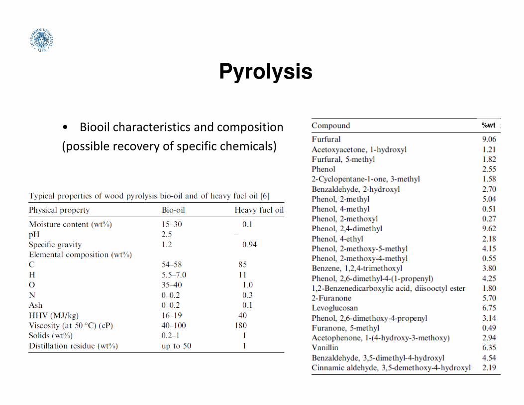
– tar (bio-oil) is a mix of organic compounds and water. After
separation the NCV is 20-25 MJ/kg and thus can be used as fuel.
As a matter of fact, it is unstable and corrosive (high O content)
and requires an upgrading step.

Pyrolysis
• Products of pyrolysis. Selectivity:
– char yield is favored by slow heating, long residence time, relatively low
final temperature (350-500°C) (slow pyrolysis and carbonization);
– tar (bio-oil) is favored by high heating rate (>100°C/s), short residence
time (<1 s) and moderate temperature (450°C for biomass and 550-600°C
for coal) (flash or fast pyrolysis, liquefaction);for coal) (flash or fast pyrolysis, liquefaction);
– gas is favored by high heating rate and high temperature (>700°C
favoring tar cracking) and relatively long residence time (1-5 s). The
presence of catalysts can maximize the yield in H2 or CH4.
(%wt typical yields) Bio-oil Char Gas
Slow pyrolysis 30 35 35
Fast pyrolysis 75 12 13
Gasification 3 10 87

Pyrolysis
• Slow pyrolysis. Biomass is pyrolysed at slow heating rates (5–7 K/min)
generally in fixed bed reactors. This leads to less liquid and gaseous
product and more of char production.
• Fast pyrolysis. It involves rapid heating (100°C/s) of biomass to
increase the yield of liquid product. Fast pyrolysis is successful with
most of fluidized bed reactors. offering high heating rates, rapid de-most of fluidized bed reactors. offering high heating rates, rapid de-
volatilization, easy control, easy product collection.
• Flash pyrolysis is the process in which the reaction time is of only few
seconds or even less. The heating rate is very high. This requires
special reactor configuration (entrained flow or fluidized bed
reactors) and small particles (100–250 µm) for producing biooil.
• Catalytic biomass pyrolysis is introduced to improve the quality of the
oil produced.

Pyrolysis
• Products of fast pyrolysis from a biomass at different temperatures
60
70
Yie
lds o
f p
rod
ucts
(%
wt)
char
0
10
20
30
40
50
200 300 400 500 600 700
T (°C)
Yie
lds o
f p
rod
ucts
(%
wt)
bioolio
chargas

Pyrolysis
• Biomass pyrolysis plant (Dynamotive, 100t/d, West Lorne) with
bubbling fluidized bed.

Pyrolysis
• Pilot pyrolysis plant (30 kg/h, Netherlands) with a cyclone reactor.

Pyrolysis
• Pilot pyrolysis plant (NREL) with an ablative reactor. Ablative pyrolysis
processes involve the contact between the biomass residue and a hot
reaction surface, which also performs mechanical ablation of the
biomass surface removing the char layers formed.
Conceptual scheme of the ablative pyrolysis of wood
on a rotating dish

Pyrolysis
• Comparison and perspectives of pyrolysis technologies

Pyrolysis
• Pyrolysis oil utilization options
Pyrolysis
• Biooil characteristics and composition
(possible recovery of specific chemicals)
%wt

Pyrolysis
• Industrial scale fast pyrolysis plants currently and recently operating
and their status in the end of 2012 (IEA).

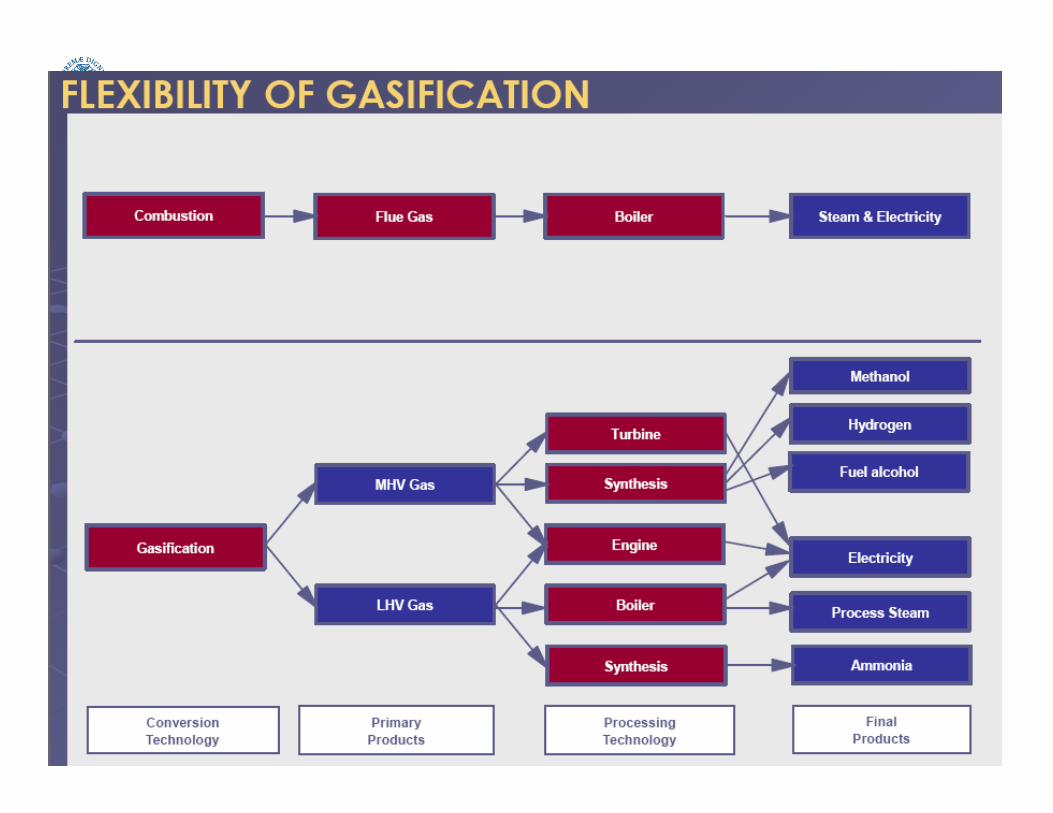
Gasification
• Thermal conversion of a solid fuel in syngas through
partial oxidation / gasification reactions.
• Gasifying agent: air, enriched air, oxygen (/steam)
• Raw syngas formed mainly of (N2), CO and H2, with
significant amount of CO2, H2O, CH4, pollutantsignificant amount of CO2, H2O, CH4, pollutant
precursors, tar and dust.
• After appropriate gas cleanup, possible uses of syngas for
combustion (boiler, engine, turbine for CHP production)
or chemical synthesis.
• Possible IGCC application, more feasible for medium-large
scale plants (>50 MW) due to complexity and high costs.

Gasification
• Different types of gasification reactors
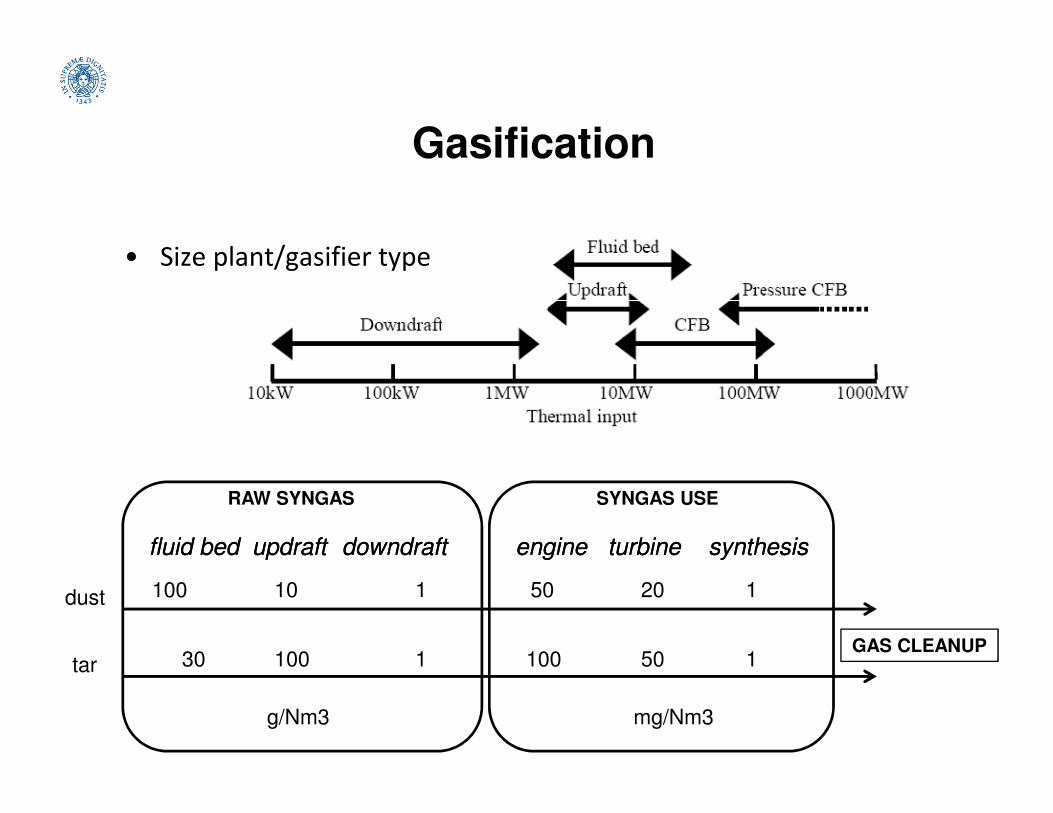
Gasification
• Size plant/gasifier type
GAS CLEANUP
RAW SYNGAS
100 1
fluidfluid bedbed downdraftdowndraftupdraftupdraft
10dust
tar 30 1100
g/Nm3
SYNGAS USE
50 1
engineengine synthesissynthesisturbineturbine
20
100 150
mg/Nm3

Gasification
Downdraft Updraft Bubbling Circulating Entrained
Top (°C) 700-1200 700-900 < 900 < 900 1500
Tgas (°C) 700 200-400
Fuel size
(mm)
20-100 5-100 0.5-5 0.5-5 < 0.5
Ash
(% dry)
0.5
(max 6)
1.4
(max 25)
<25 <25 high
(% dry) (max 6) (max 25)
Pros •Simple technology
•Low costs
•High thermal coefficient
•High reaction rate
•Uniform temperature
•Medium-large scale plants
•Large scale plants
•High efficiency
•Possible inert solid
residuesRelatively low
dust and tar
syngas
Relatively
high
moisture
fuel
Cons Only small scale plants
(40-1000 kW)
•High tar and dust syngas
•Complex technology
•Specific range of fuel size
•Complex technology
•Specific range of fuel
size
•High costsSpecific range
of fuel size and
moisture
High tar
syngas

Gasification

Gasification
• Biomass gasification: state of the art and predictions

Gasification
• Fixed bed downdraft gasifier at CRIBE (Centro Interuniversitario Biomasse per Energia, S.Piero a Grado – PI):
Loading LC max
Vegetable-oil towers
CondenserFlare
possible inclusion ofinternal combustion
engine for CHP production
Biomass
Tank
Loading
System
Gasifier
LC min
Air
To water
collection
Particulate
Cyclone
Condenser
Sawdust
Filters
Bag
Filter
Chiller
Blower
from cooling tower
to water
collection
TC0
FI
TC1
TC2
TC3
∆P
∆P
∆P ∆P ∆P
∆P
Cooler
Venturi
40-80 kg/h of biomass (15% moisture, 20-80 mm),
syngas LHV 5-6 MJ/Nm3,
potential electric efficiency 22-26%

Gasification
• Main reactions in the fixed downdraft gasifier:
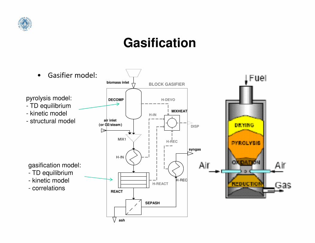
Gasification
• Gasifier model:
DECOMP
MIXHEAT
air inlet
biomass inlet
H-DEVO
H-IN
BLOCK GASIFIER
pyrolysis model:
- TD equilibrium
- kinetic model
- structural model
MIX1
H-IN
REACT
H-REC
SEPASH
air inlet
(or O2/steam )
ash
syngas
H-REACT
H-REC
DISP
- structural model
gasification model:
- TD equilibrium
- kinetic model
- correlations
Gasification
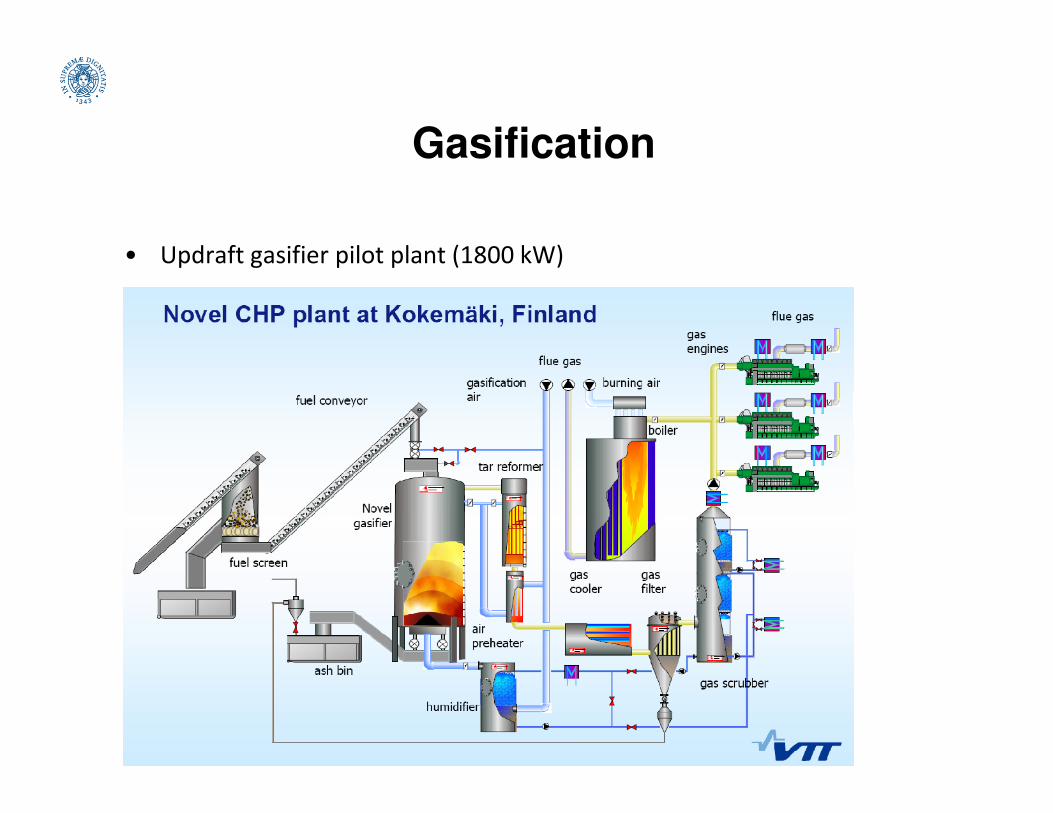
• Updraft gasifier pilot plant (1800 kW)

Gasification
• FLUIDIZED BED GASIFICATION
In a fluidized bed gasifier, air and fuel are mixed in a hot bed of granular solids
such as sand. Due to the intense gas–solid mixing in a fluidized bed, the
different zones — drying, pyrolysis, oxidation, reduction — cannot be
distinguished, but the temperature is uniform throughout the bed.
Contrary to fixed bed gasifiers the air-to-fuel ratio can be changed, and as aContrary to fixed bed gasifiers the air-to-fuel ratio can be changed, and as a
result the bed temperature can be controlled easily.
The product gas will however, always contain some tar, which needs to be
removed. Furthermore, high solid conversion is hardly achieved. Particle
entrainment from a bubbling bed also contributes to the loss in a gasifier.
The other important problem with FB gasifiers is the slow diffusion of the oxygen
from the bubbles to the emulsion phase, which creates oxidizing conditions in
the whole bed decreasing the gasification efficiency.
The circulating fluidized bed (CFB) can get around this problem by providing
longer solid residence time within its solid circulation loop.

Gasification
• FLUIDIZED BED GASIFICATION
Fluidized bed is especially good for biomass gasification. So far as coal
gasification is concerned, fluidized beds have found only limited application
because of their low carbon conversion efficiency, which results from the
relatively low bed temperatures (800 to 1000°C) needed to avoid ash
agglomeration.agglomeration.
Since fluidized bed gasifiers operate at relatively low temperatures, most reactive
and high-ash content fuels, depending on ash chemistry, can be gasified in
such beds without the problem of ash sintering and agglomeration.
Also, fluidized bed gasifiers can be operated on different types of fuels or a
mixture of different fuels. This feature is especially attractive for biomass
fuels, such as agricultural residues and wood, that may be available for
gasification at different times of the year.

Gasification
• This is an atmospheric-pressure air-blown
gasifier operating in a circulating fluidized
bed. Depending on the fuel and the
application, it operates at a temperature
within the range of 800 to 1000°C.
• The hot gas from the gasifier passes• The hot gas from the gasifier passes
through a cyclone, which separates most
of the solid particles associated with the
gas and returns them to the bottom of the
gasifier. An air preheater is located below
the cyclone to raise the temperature of
the gasification air and indirectly the
temperature level inside the gasifier.

Gasification
• The integrated gasification combined-cycle (IGCC) process involves
complete gasification of the fuel. The cooled, medium-heating-value
gas is desulfurized and dedusted, and burnt in the combustor of a gas
turbine to produce electricity.
• Waste flue gas from the turbine is used to heat the water for the
boiler. Steam from the boiler produces additional electricity in aboiler. Steam from the boiler produces additional electricity in a
steam turbine.
• The combined efficiency of this process is in the range of 42 to 45%.
The waste gas leaves the gas turbine at a relatively low temperature,
thus it cannot produce high-temperature steam.
• The cost-effectiveness and overall plant availability of this system
have to be evaluated against other options. The power generation
cost is not yet competitive with conventional plants, but government
supports and emission credits might make this option viable.

Gasification
ExhaustExhaust gasgas
HeatHeat
Integrated combined-cycle plant
(scheme)

Gasification
Combined-cycle plant using
partial gasification of coal
Gasification
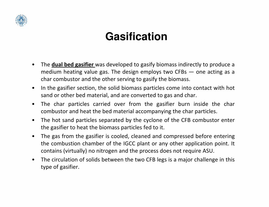
• The dual bed gasifier was developed to gasify biomass indirectly to produce a
medium heating value gas. The design employs two CFBs — one acting as a
char combustor and the other serving to gasify the biomass.
• In the gasifier section, the solid biomass particles come into contact with hot
sand or other bed material, and are converted to gas and char.
• The char particles carried over from the gasifier burn inside the char• The char particles carried over from the gasifier burn inside the char
combustor and heat the bed material accompanying the char particles.
• The hot sand particles separated by the cyclone of the CFB combustor enter
the gasifier to heat the biomass particles fed to it.
• The gas from the gasifier is cooled, cleaned and compressed before entering
the combustion chamber of the IGCC plant or any other application point. It
contains (virtually) no nitrogen and the process does not require ASU.
• The circulation of solids between the two CFB legs is a major challenge in this
type of gasifier.

Gasification
• The dual bed gasifier:
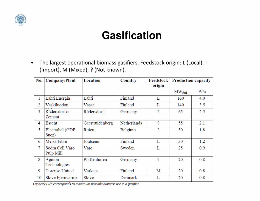
Gasification
• The largest operational biomass gasifiers. Feedstock origin: L (Local), I
(Import), M (Mixed), ? (Not known).