formalizing architectural patterns with the goal … · formalizing architectural patterns with the...
TRANSCRIPT
Formalizing Architectural Patterns
with the Goal-oriented Requirement
Language
Gunter Mussbacher1, Michael Weiss2 and Daniel Amyot1
1 SITE, University of Ottawa, Ottawa, Canada
2 SCS, Carleton University, Ottawa, Canada
Abstract. Many pattern descriptions put their emphasis on the solution to
a problem rather than on often conflicting forces and how patterns balance
such forces. This work uses the Goal-oriented Requirement Language
(GRL) to formalize the forces of architectural patterns in a way that en-
ables rigorous trade-off analysis while allowing the pattern user to deter-
mine the applicability of a pattern to the problem in a given context. The
formalization of forces does not replace other pattern descriptions but
rather complements them and relies on them to provide descriptions of the
problem and solution. This work presents a description of the forces appli-
cable in the context of architectural design, introduces how to represent
patterns and forces with GRL, and then formalizes a subset of a recently
published architectural pattern language.
INTRODUCTION
Patterns enable an efficient transfer of experience by documenting common solutions
to recurring problems in a specific context. Much of the work on pattern documentation
such as the Pattern Almanac (Rising, 2000) and pattern formalization (Taibi and Ngo,
2001) focuses on the solution domain. However, they seldom formalize the problem do-
main and relevant trade-offs between the various (and often conflicting) forces involved.
Still, patterns need to be described and formalized in ways that enable the reader to de-
13
termine whether the particular solution presented is useful and applicable to his or her
problem in a given context
To address this issue, we use the Goal-oriented Requirement Language (GRL) (URN
Focus Group, 2003a) to formalize pattern forces and problem domains in a way that sup-
ports a rigorous trade-off analysis. We apply this GRL-based formalization to a recently
published pattern language (Avgeriou and Zdun, 2005). The pattern language covers 23
architectural patterns categorized into eight groups according to their applicability to a
specific architectural view.
In the following sections, we first present the background for patterns and the formal-
ization of patterns. Then, we introduce the GRL as part of the User Requirements Nota-
tion and our explicit model of pattern forces which provides the basis for the trade-off
analysis. This is followed by the formalization of a subset of the architectural pattern lan-
guage to which we have applied our approach, including a brief description of the forces
applicable in the domain of architectural design. Future trends and remarks conclude this
paper.
FORMALIZING PATTERNS
Patterns describe a recurring problem that occurs in a specific context and its solution
(Alexander, 1979). One of their most significant contributions is that they intend to make
explicit the trade-offs between the forces involved. Each pattern describes the situation
when the pattern can be applied in its context. The context can be thought of as a precon-
dition for the pattern. This precondition is further refined in the problem description with
its elaboration of the forces that push and pull the system to which the pattern is applied
in different directions. Here, the problem is a precise statement of the design issue to be
solved. Forces are design trade-offs affected by the pattern. They can be documented in
various forms. One popular approach is to document the trade-offs as sentences like “on
one hand …, but on the other hand …”.
The solution describes a way of resolving the forces. Some forces may not be re-
solved by a single pattern. In this case, a pattern often includes references to other pat-
terns, which help resolve forces that were unresolved by the current pattern. Together,
patterns connected in this way are often referred to as a pattern language. Links between
Applying Patterns
14

patterns can be of different types, including uses, refines, and conflicts. Patterns that need
another pattern link to that pattern with uses. Patterns specializing the context or problem
of another pattern refine that pattern. Patterns that offer alternative solutions conflict.
Current pattern representations are textual. They include the Gang-of-Four (GoF)
form, the Coplien form, and the Alexandrian form. The GoF form (Gamma et al., 1994)
includes sections for intent, motivation, structure, participants, and collaborations. The
emphasis of this format is on the structure of the solution. However, the discussion of the
forces is spread out over multiple sections, which makes it challenging for a developer to
get an overview of when to apply a particular pattern and the consequences of using it.
Motivated by this drawback of the GoF form, the Coplien form (Coplien, 1996) de-
fines a more rigid pattern structure. It includes explicit sections for forces and conse-
quences, in which the forces and the implications of using the patterns are presented in
bullet form. This provides quick access to the reasons for applying a pattern. Variations
of this format have been proposed that present the forces/consequences as tables.
Recently, many pattern authors have returned to the Alexandrian pattern form (Alex-
ander, 1979). It resolves the trade-off between the needs to have structure on the one
hand, and the desire to create more easily readable pieces of literature, on the other. In
practical use for documenting software designs, the Alexandrian form has been adapted
to include the concept of explicit lists of forces and consequences from the Coplien form.
Nonetheless, with these formats there are still open issues: how to recognize under
what conditions a given pattern should be selected, how to compare between different
patterns that address the same problem, and how to integrate the consequences of apply-
ing a pattern or a combination of patterns into an integrated model. It is with these issues
in mind that we propose a formalization of patterns using the Goal-oriented Requirements
Language in a way that supports a rigorous trade-off analysis during the application of
design patterns while maintaining the generality of the solution description.
Previously, (Araujo and Weiss, 2002) have proposed an explicit representation of the
forces involved in a pattern and their inter-relationships. This representation suggests in-
terpreting forces as functional and – mainly as – non-functional requirements, and uses
the Non-Functional Requirements (NFR) framework (Chung et al., 2000) to analyze
forces and the trade-offs made by a pattern.
Formalizing Architectural Patterns with the Goal-Oriented Requirement Language
15

In related earlier work, (Ong, Weiss, and Araujo 2003) derived the forces affected by
a pattern through a close reading of the textual pattern description. The extended pattern
representation enabled them to discover contributions made by the patterns to overall sys-
tem concerns that were only implicit in their textual descriptions. Their main finding was
that the contributions of each pattern to overall system concerns became much more ap-
parent than what could be gleaned from reading the pattern descriptions alone.
Our approach is similar, at the level of individual patterns, to the work by (Gross and
Yu, 2001), as well as (Chung et al., 2002). Both present ways of reasoning about patterns
using NFRs. However, there are important differences. We are also concerned with the
connections between patterns at the pattern language level, as well as with establishing
models of the forces and their trade-offs that exist in a particular domain. As a result, we
feel that our results are farther-reaching, and will lead to a more objective approach.
USER REQUIREMENTS NOTATION
The User Requirements Notation (URN) is a standardization effort of the Interna-
tional Telecommunications Union (ITU) and published in the Z.150 series of Recom-
mendations (ITU-T, 2003). URN is a high-level modeling notation that makes use of
goals and scenarios to model and analyze user requirements in a more formal way. The
notation is generally suitable for the description of most types of reactive, concurrent, and
distributed systems and services; e.g. telecommunications systems, e-commerce systems,
agent systems, operating systems, and health information systems. URN is also a conven-
ient notation for business process modeling and evolution (Weiss and Amyot, 2005). An
overview of URN with a tutorial example from the wireless communication domain is
presented in (Amyot, 2003).
URN consists of two complementary notations. Use Case Maps (UCMs) (URN Focus
Group, 2003b) allow the specification of behavior and structure. The Goal-oriented Re-
quirement Language (GRL) (URN Focus Group, 2003a) represents goals and stake-
holders. Both notations are useful in the context of formalizing pattern forces and solu-
tions, and for trade-off analysis. UCMs are particularly useful for modeling structural and
behavioral aspects of the solution part of patterns (e.g. the consequences of applying pat-
terns in terms of the architectural design of a system), whereas GRL is a valuable tool to
Applying Patterns
16

model pattern forces and their interactions. This work focuses on the later. GRL comple-
ments the NFR (Non-Functional Requirements) framework published in (Chung et al.,
2000) with agent modeling concepts from the i* framework (Yu, 1997). GRL captures
business or system goals, stakeholder concerns, alternative means of achieving goals, and
the rationale for goals and alternatives. Alternatives are evaluated in terms of their impact
on goals and stakeholder concerns. The notation is applicable to functional requirements,
but it is especially good for capturing and reasoning about the interaction of non-
functional requirements. See Figure 1 for a summary of the main notation elements of
GRL.
Satisficed
Weakly Satisficed
Undecided
Weakly Denied
Denied
Conflict
(b) GRL Satisfaction Levels
Satisficed
Weakly Satisficed
Undecided
Weakly Denied
Denied
Conflict
Satisficed
Weakly Satisficed
Undecided
Weakly Denied
Denied
Conflict
(b) GRL Satisfaction Levels
Dependency
Contribution
Correlation
Means-end
Decomposition
(d) GRL Links
Dependency
Contribution
Correlation
Means-end
Decomposition
DependencyDependency
ContributionContribution
CorrelationCorrelation
Means-endMeans-end
DecompositionDecomposition
(d) GRL Links
?Break Hurt Some- Unknown
Make Help Some+ Equal
(e) GRL Contributions Types
?Break Hurt Some- Unknown
Make Help Some+ Equal
??Break Hurt Some- Unknown
Make Help Some+ Equal
(e) GRL Contributions Types
OR
AND
(c) Link Composition
OROR
ANDAND
(c) Link Composition
Goal
Softgoal
Belief
Actor
ActorBoundary
Resource
(a) GRL Elements
Task
Goal
SoftgoalSoftgoal
BeliefBelief
ActorActor
ActorBoundary
ActorBoundary
Resource
(a) GRL Elements
Task
Figure 1. Summary of the GRL notation
FORMALIZING FORCES FOR TRADE-OFF ANALYSIS
We use GRL graphs to explicitly model the forces addressed by a pattern, the ration-
ale behind them, the relationships between patterns, the contribution of a pattern to the
system, and the stakeholders’ interest in various aspects of the system. The GRL graph in
Figure 2 shows the contributions of an individual pattern to its forces.
Forces are represented as softgoals (clouds), indicating that these cannot be achieved
in an absolute manner. Patterns are modeled as tasks (hexagons), representing ways of
Formalizing Architectural Patterns with the Goal-Oriented Requirement Language
17
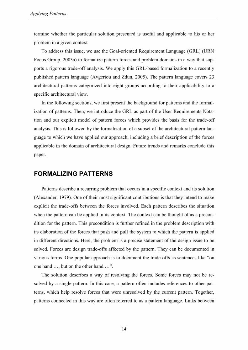
achieving a softgoal. The nodes of this goal graph are connected by different types of
links. Direct contributions of a pattern to softgoals are shown as solid lines. Side effects
(indirect contributions called correlations) are shown as dotted lines. The kind of contri-
bution is determined by labels, indicating various degrees of positive (+) or negative (-)
contributions (see Figure 1e for the complete set of labels). The complexity of the system
dictates the number of levels of forces (e.g. two in Figure 2), but there is at least one level
of forces.
Figure 2. Modeling individual pattern – Alternative 1
Observation 1. There is only a subtle difference between forces and non-functional
requirements. This difference manifests itself in non-functional requirements being at the
top of the hierarchical structure of forces (i.e. at the bottom of Figure 3). The reason for
this arrangement is that forces push or pull the system towards or away from non-
functional requirements (e.g. better performance or greater security). As forces connect
patterns and non-functional requirements, they provide an explanation of why a pattern
impacts a non-functional requirement the way it does.
Therefore, model non-functional requirements also with softgoals. Show them on the
same GRL graph in order to provide a visual connection between a pattern and the non-
functional requirements addressed by the pattern. There is always one level of non-
functional requirements in the GRL graph of an individual pattern. With tool support, the
relationships between forces and non-functional requirements could be defined on a sepa-
rate GRL graph and then automatically added to the GRL graphs for individual patterns
in Figure 2.
Applying Patterns
18
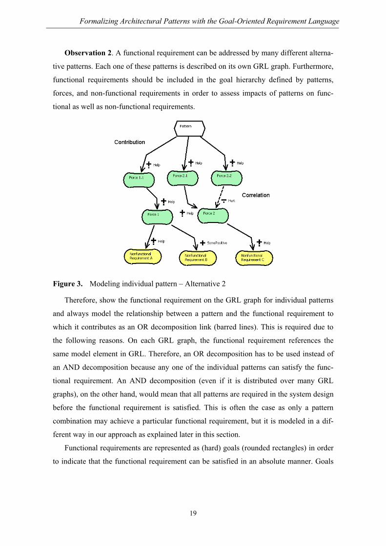
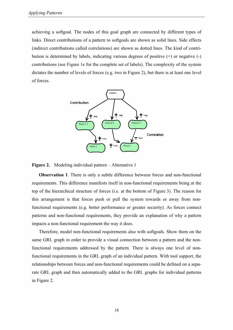
Observation 2. A functional requirement can be addressed by many different alterna-
tive patterns. Each one of these patterns is described on its own GRL graph. Furthermore,
functional requirements should be included in the goal hierarchy defined by patterns,
forces, and non-functional requirements in order to assess impacts of patterns on func-
tional as well as non-functional requirements.
Figure 3. Modeling individual pattern – Alternative 2
Therefore, show the functional requirement on the GRL graph for individual patterns
and always model the relationship between a pattern and the functional requirement to
which it contributes as an OR decomposition link (barred lines). This is required due to
the following reasons. On each GRL graph, the functional requirement references the
same model element in GRL. Therefore, an OR decomposition has to be used instead of
an AND decomposition because any one of the individual patterns can satisfy the func-
tional requirement. An AND decomposition (even if it is distributed over many GRL
graphs), on the other hand, would mean that all patterns are required in the system design
before the functional requirement is satisfied. This is often the case as only a pattern
combination may achieve a particular functional requirement, but it is modeled in a dif-
ferent way in our approach as explained later in this section.
Functional requirements are represented as (hard) goals (rounded rectangles) in order
to indicate that the functional requirement can be satisfied in an absolute manner. Goals
Formalizing Architectural Patterns with the Goal-Oriented Requirement Language
19

allow us to reason about the functional requirements to which a pattern contributes. Func-
tional requirements are shown at the top of Figure 4.
Even though our examples only show one functional requirement on the GRL graphs
for individual patterns, our pattern representation is not at all limited to just one such
goal. Many different goals describing many different functional requirements may be
shown on a GRL graph and may be connected with decomposition links to individual pat-
terns.
Figure 4. Modeling individual pattern – Alternative 3
Observation 3. Often, an individual pattern makes use of other patterns. The contri-
butions of these patterns to functional and non-functional requirements have already been
defined on their individual GRL graphs. They should only be created once.
Therefore, show the composition of pattern with decomposition links on the GRL
graph of the individual pattern. Figure 5 constitutes the complete structure of the GRL
graph for an individual pattern.
Decomposition links between tasks allow various relationships between patterns to be
modeled (e.g. uses, refines, and conflict relationships). Figure 5 shows that “Pattern” uses
“Pattern A” and “Pattern B”. The impact of “Pattern A” and “Pattern B” on forces, non-
Applying Patterns
20

functional requirements, and functional requirements is shown on their own individual
GRL graphs. Therefore, GRL graphs for an individual pattern establish reusable models
of forces applicable to many domains.
Figure 5. Modeling individual pattern
Observation 4. If a pattern combination is a pattern in itself, then the GRL graph for
individual patterns is used to describe the pattern combination (see Figure 5). A pattern
combination, however, may not be a pattern in itself, but may just represent the usage of
several patterns together. Considering the composite pattern, there should not be a differ-
ence in our representation between an actual pattern and a pattern combination. Patterns
and pattern combinations should be used interchangeably, allowing both to be considered
as alternatives for a functional requirement. However, if a pattern combination is not a
pattern, then there is no need to model forces and the impact of forces on non-functional
requirements.
Therefore, simplify the GRL graph for an individual pattern into the GRL graph for a
pattern combination (see Figure 6). Figure 6 addresses the point in observation 2 regard-
ing AND decompositions of a functional requirement into many patterns (“Pattern A”
Formalizing Architectural Patterns with the Goal-Oriented Requirement Language
21

and “Pattern B”) by explicitly modeling the pattern combination as a task (“Pattern Com-
bination”).
Figure 6. Modeling pattern combinations
Observation 5. A GRL graph for an individual pattern shows all forces and non-
functional requirements impacted by the pattern, irrespective of the current system to be
designed. Not all non-functional requirements, however, may be of interest to stake-
holders in the context of any specific system design task. As it should be possible to reuse
these graphs as is for each system to be designed, the stakeholders’ interest in particular
non-functional requirements has to be modeled with additional GRL graphs.
Figure 7. Modeling stakeholder concerns
Therefore, the stakeholders of a system and the system itself are modeled as GRL ac-
tors (dotted circles) with dependency links (lines with filled direction symbol) between
them identifying only the non-functional requirements of interest to a particular stake-
holder. The GRL graph for stakeholder concerns in Figure 7 shows that stakeholder A
depends on the system to provide “Nonfunctional Requirement A” and “Nonfunctional
Applying Patterns
22

Requirement C”. Note that dependency links may connect non-functional requirements
with subgoals instead of the main functional goal as shown in Figure 7.
Like most goal-oriented languages, GRL supports propagation algorithms to evaluate,
for a given strategy, to what degree the goals and softgoals in a model are satisfied (URN
Focus Group, 2003a). A strategy assigns initial satisfaction values to some of the ele-
ments in the model which are then propagated to the other elements connected by contri-
bution, correlation, and decomposition links. This enables one to make a qualitative,
rapid, and global assessment of the impact of a particular choice and hence to find the
most appropriate trade-off in a given context.
Observation 6. Our pattern representation consists of two hierarchies – one for non-
functional requirements and one for functional requirements. The top level of both hierar-
chies is shown on the GRL graph for stakeholder concerns. The main functional require-
ments are refined into subgoals until a subgoal can be addressed by a pattern or pattern
combination (e.g. one subgoal could be that the system needs to process streams of data
which is addressed by patterns in the Data Flow View group of the architectural pattern
language). This subgoal is then referenced on GRL graphs of applicable individual pat-
terns or pattern combinations, and decomposed with an OR decomposition into the pat-
tern or pattern combination, respectively. Non-functional requirements are also refer-
enced on the GRL graphs of applicable individual patterns or pattern combinations. They
are connected via contribution or correlation links to forces which in turn are eventually
connected to the pattern or pattern combination, respectively.
Therefore, patterns and pattern combinations are at the bottom of both hierarchies and
represent possible solutions to functional and non-functional requirements. Furthermore,
the patterns and pattern combinations are also the model elements to which initial satis-
faction values for the propagation algorithm should be assigned in order to evaluate alter-
nate solutions. The initial values are propagated upwards the hierarchies to the GRL
graph for stakeholder concerns where the final evaluation is shown. The two hierarchies
ensure that the chosen solution is evaluated in terms of its impact on functional and non-
functional requirements, avoiding cases where a solution satisfies only functional re-
quirements at the cost of non-functional requirements or vice versa. Note that the propa-
gation algorithm combines the contributions of several patterns or pattern combinations
to a particular non-functional requirement even if the contributions to the non-functional
Formalizing Architectural Patterns with the Goal-Oriented Requirement Language
23

requirement are shown on several GRL graphs. The combined result is global and shown
on each GRL graph.
Figure 8. Investigating the impact of a pattern
Figure 8 shows the evaluation of an individual pattern with regards to its forces, func-
tional requirements, and non-functional requirements. The evaluation results are indicated
for each node of the goal graph with various checkmarks (positive) and crosses (negative)
(see Figure 1b for the complete set of evaluation results) as well as numbers between
-100 (denied) and 100 (satisfied). Initial values are marked with a star (*) on the evalua-
tion diagram. Note that in order to assess the full impact of the individual pattern, all pat-
terns used by the individual pattern (i.e., “Pattern A” and “Pattern B”) must have their
initial satisfaction values set to 100. This ensures that the contributions of the patterns
used by the individual pattern are taken into account for the evaluation of forces, non-
functional requirements, and functional requirements. If the initial satisfaction values of
“Pattern A” or “Pattern B” are changed in Figure 8, the results for those forces, non-
Applying Patterns
24

functional requirements, and functional requirements that also occur on the individual
GRL graphs for “Pattern A” or “Pattern B” will be different.
Finally, Figure 9 shows the evaluation results from the stakeholder’s point of view.
The evaluation value of the main functional goal of the system is calculated (in this case
it is not satisfied because only one of the two subgoals is satisfied) and the evaluation
values of the non-functional requirements the stakeholder is interested in are shown. Note
that these values match the values on the GRL graphs for individual patterns or pattern
combinations.
Figure 9. Assessing evaluations from the stakeholder’s point of view
Observation 7. As with all modeling techniques, the usefulness of our technique pre-
sented in this section depends on how easily the technique can be included into general
software development processes. A pre-condition to our technique is that regular pattern
descriptions are extended to include our formalized, reusable description of pattern forces
as suggested in this section (see Figure 5). Note that the presence of our GRL models
does neither preclude the existence of other representations and formalizations nor does it
require a particular pattern template.
Therefore, indicate what changes are most likely required to incorporate our tech-
nique into a general software development process.
1. Compile a list of stakeholders for the system. This process step should already be
in place.
2. For each stakeholder, create a GRL graph for stakeholder concerns by identifying
the non-functional requirements of interest to the stakeholder (see Figure 7; space
permitting, more than one stakeholder may be shown on one GRL graph). The
Formalizing Architectural Patterns with the Goal-Oriented Requirement Language
25

identification of stakeholder concerns should already be a part of the process but
visual modeling is an addition.
3. Refine the system’s main functional goal into subgoals. This step also should be
in place and again is done additionally in a visual way. Two cases have to be con-
sidered at this step:
a. If the subgoal matches a functional goal identified in the pattern catalogue on
one of the GRL graphs for individual patterns or pattern combinations, it is
very likely that the subgoal does not need to be refined further. The list of
goals identified in the pattern catalogue can actually be used to guide the re-
finement of goals.
b. If the subgoal does not match a functional goal identified in the pattern cata-
logue, then again there are two choices:
i. Further refine the subgoal until the refinement produces a matching sub-
goal.
ii. Stop refinement of the subgoal and create a new pattern combination (see
Figure 6) that addresses the specific need of this subgoal. A recurring,
new pattern combination may even lead to a new pattern to be added to
the pattern catalogue.
iii. Stop refinement of the subgoal and address the subgoal with a solution
that does not make use of patterns. The impact of this particular solution
on functional and non-functional requirements can still be modeled. This,
however, is only necessary if we are concerned with modeling the com-
plete system regardless of whether patterns are used or not. If our goal is
to "only" compare alternative patterns, indicate the trade-offs, and pro-
vide assistance in choosing the best pattern for the given subgoal, then
we may not need to be concerned about non-pattern choices.
4. Connect the main goal or relevant subgoals with the stakeholder’s non-functional
requirements. In a general software development process, this is most likely not
done explicitly to the extent required by our technique.
5. Determine the most suitable pattern or pattern combination by using tool-
supported trade-off analysis based on GRL strategies. This is currently done in an
ad-hoc manner in the worst case and with tool support in the best case.
Applying Patterns
26
The focus of the suggested process is on comparing patterns. The comparison simply
shows the different impact the patterns have. It captures the information that is currently
provided in the forces and consequences sections of a pattern description. The visualiza-
tion, however, allows us to more readily see what impact the selection of a pattern or a
group of patterns will have. The context for the pattern is defined by prioritizing the non-
functional requirements (see step 2), thereby adapting the pattern to the environment. As
indicated earlier on, our approach does not model the solution part of a pattern which is
arguably the part where most of the variations happen when a pattern is used in a new
context. The approach focuses on the more stable part of the forces and relationships be-
tween forces. By understanding the interaction of forces, the user is given the ground-
work required to adapt the pattern in a new situation.
FORMALIZING ARCHITECTURAL PATTERNS
Observation 8. The bottom half of Figure 3 suggests that there are relationships be-
tween forces and non-functional requirements that are independent of patterns.
Therefore in this section, we formalize the relationship between forces and non-
functional requirements in the domain of architectural design based on the discussion of
eight non-functional requirements in chapter 2 of (Dyson and Longshaw, 2004):
1. Availability (see Figure 10) – the “working hours” of the system (the amount of
time the system is up and running).
2. Performance (see Figure 11) – ability of the system to provide a timely response.
3. Scalability (see Figure 12) – ability to ensure performance when the number of
users grows.
4. Security (see Figure 13) – ability to ensure access control and privacy of informa-
tion.
5. Manageability (see Figure 14) – ability to monitor and adjust the system’s runtime
behavior.
6. Maintainability (see Figure 15) – the ease with which problems are fixed.
7. Flexibility (see Figure 16) – the ease with which new functionality and new non-
functional characteristics are provided for a system.
Formalizing Architectural Patterns with the Goal-Oriented Requirement Language
27

8. Portability (see Figure 16) – the ease with which a system is migrated to a new
operating environment.
Figure 10 to Figure 16 depict the forces and how each force impacts another force or
non-functional requirement as mentioned in chapter 2 of (Dyson and Longshaw, 2004).
The set of forces is not necessarily complete as it only reflects the forces mentioned by
(Dyson and Longshaw, 2004). Other authors may want to add additional forces or rela-
tionships. The GRL graphs, however, make these forces and relationships more explicit,
allowing easier identification and addition of other forces.
Reflecting the nature of forces at play for architectural design, the forces in the GRL
graphs are at different levels of abstraction and cover very different things (e.g. “More
robust against failure” and “Average number of users increases with time”). The GRL
graphs do not prescribe a certain level of abstraction and can certainly cover very differ-
ent things, because the goal of GRL graphs is to show all issues that have to be consid-
ered in a certain situation and how these issues interact with each other. The degree of
contribution is used to show the importance of a force.
If the meaning of one force is not clear from its label, it is often helpful to look at the
forces that contribute to the force. Alternatively, a more elaborate description or defini-
tion can be attached to the force.
Figure 10. Forces of architectural design that impact availability
Reading the GRL graphs reveals the forces in the architectural domain. For example,
Figure 10 indicates that “Use redundant or replicated system elements HELPs availabil-
ity.” The whole sentence expresses an invariant, consisting of a force and, in this case, its
Applying Patterns
28

impact on a non-functional requirement. The invariant has to be considered and under-
stood for the domain in question. The wording of a force can be a matter of discussion.
Some styles prefer the force to be worded with a keyword (similar to requirements, e.g.
shall). Such styles can certainly be incorporated into our formalization. The main point is
that the GRL graphs clearly identify forces, enabling a discussion on wording, etc.
Figure 11. Forces of architectural design that impact performance
Figure 12. Forces of architectural design that impact scalability
Figure 13. Forces of architectural design that impact security
Formalizing Architectural Patterns with the Goal-Oriented Requirement Language
29

Figure 14. Forces of architectural design that impact manageability
Figure 15. Forces of architectural design that impact maintainability
Figure 16. Forces of architectural design that impact flexibility and portability
Applying Patterns
30

As an example, we have applied our pattern formalization to one of the architectural
views described in (Avgeriou and Zdun, 2005). The Layered View is concerned with how
interacting parts of a system remain decoupled. Two patterns are classified under the
Layered View: Layers and Indirection Layer (see Figure 17).
Figure 17. Layers (left) and Indirection Layer (right)
Figure 17 helps us conclude that the patterns impact performance more or less nega-
tively and maintainability, flexibility, and portability positively because it references the
softgoals “Isolate system elements through abstraction and generalization” and “Addi-
tional Processing” which also occur in Figure 11, Figure 15, and Figure 16.
Figure 10 to Figure 17 represent one complete view of the system in terms of forces
and non-functional requirements. Other views, however, can be created if they are
deemed useful by rearranging the forces and non-functional requirements. The relation-
ship between the pattern “Layers” and the non-functional requirements performance,
maintainability, flexibility, and portability is shown indirectly in Figure 17 with the help
of the referenced softgoal “Isolate system elements through abstraction and generaliza-
tion”. In this case, the organization of the GRL graphs favors reusability of the graphs in
Figure 10 to Figure 16 over directly showing, on a single GRL graph, the impact of the
Formalizing Architectural Patterns with the Goal-Oriented Requirement Language
31
pattern “Layers” on non-functional requirements. The latter view, however, can be easily
created from the presented GRL graphs.
DISCUSSION AND FUTURE TRENDS
This example demonstrates how GRL graphs capture pattern forces and can be used
to assess the qualitative impact of various solutions to a functional goal, in context. The
benefits of the proposed process become even more interesting as the system gets more
complex and trade-offs are more difficult to assess due to numerous interrelated contribu-
tions and side-effects.
The proposed process for URN-based trade-off analysis is not limited to individual
subgoals. It can easily be extended to pattern combinations addressing all subgoals at
once, hence providing for global impact analysis and guidance, at the system level. This
may go beyond the needs of designers and system architects who may only be interested
in solving a focused design problem, but this level of evaluation is nevertheless possible.
Obviously, in addition to having patterns formalized with URN, the more advanced
benefits require additional investments that not all modelers may be willing to make: a
system-level GRL model for assessing the global impact of selected patterns.
There is also a general trend towards formalizing aspects of patterns, whether they are
related to the relationships between patterns, or to properties of individual patterns. Often,
these efforts have been confined to certain domains, which are more amenable to formal-
ization, such as the area of security patterns. One example is the formalization of security
properties that are satisfied by application of a pattern (Wassermann and Cheng, 2003),
another is the formalization of security pattern properties in (Mouratidis et al., 2005),
which allows the authors of a pattern language to assess the completeness of the lan-
guage. In this work, the pattern solutions are modeled in agent-oriented models in the
Tropos modeling framework. A formal language for Tropos models is used to formalize
the problems, solutions, and consequences of these patterns. These properties are ex-
pressed in logic statements over the components of the solutions. Some of this logic-
based formalization could be added to GRL, although it does not appear essential in our
current trade-off analysis context.
Applying Patterns
32
Aspects, which are concerns that crosscut dominant decompositions, represent an-
other trend identifiable in the software community in general. Aspects have been studied
for a decade and are used to compensate several weaknesses of object-oriented program-
ming languages (e.g., scattering and tangling of functionalities and other concerns). Exist-
ing design patterns have been recast for new aspect-oriented languages, e.g. see (Hanne-
mann and Kiczales, 2002), whereas new patterns specific to such languages have started
to appear. More recently, aspect-oriented concepts have been included in modeling lan-
guages, closer to design and requirements. For instance, (Jacobson and Ng, 2004) present
an approach where aspects are derived from UML use cases, whereas (Yu et al., 2004)
present an approach where aspects are inferred from goal models. The impact of the
availability of such enhanced modeling languages requires further exploration. For in-
stance, we believe aspect-oriented concepts can easily be added to URN. This could help
close the gap between aspect-oriented modeling and programming languages and at the
same time open the door to new types of patterns that are more abstract or closer to re-
quirements than the current generation of design patterns.
CONCLUSION
In this paper, we have presented an approach where architectural patterns are formal-
ized with the Goal-oriented Requirements Language (GRL). Our main objective is to de-
scribe patterns in a way that the various and conflicting forces involved can guide, in a
given context, the selection of the most suitable patterns or combinations of patterns
amongst many alternatives.
Forces and contributions for individual patterns are captured using GRL. Combina-
tions and side effects (correlations) are described with AND graphs, and alternative com-
binations for a given (functional) goal are represented with an OR graph. With the help of
strategies (i.e. initial selections of candidate patterns) and propagation rules, designers
can assess the impact of their selection on the forces and find a suitable solution in their
context. This context can itself be modeled with GRL, first at the actor/dependency level
and then at the level of intentional elements (goals, softgoals, tasks, etc.) for the system.
This enables global and rigorous assessments to be made, even when many functional
sub-goals are considered.
Formalizing Architectural Patterns with the Goal-Oriented Requirement Language
33

To take full advantage of URN-based formalization of design patterns, a process was
briefly introduced and illustrated with a case study where many combinations of patterns
could be used to achieve the same functionality while leading to different trade-offs in-
volving non-functional aspects such as maintainability and performance. A prototype
Eclipse plug-in, which was used to create and evaluate the URN models presented here,
already exists to support such process, and is still evolving to support new types of analy-
ses and transformations (Roy et al., 2006).
We believe this formalization approach will provide means to get rapid and global
trade-off analysis results in context and make better use of current and future design pat-
terns.
REFERENCES
Alexander, C. (1979). A Pattern Language. Oxford University Press.
Amyot, D. (2003). Introduction to the User Requirements Notation: Learning by Exam-
ple. Computer Networks, 42(3), 285-301.
Araujo, I., and Weiss, M. (2002). Linking Non-Functional Requirements and Patterns.
Conference on Pattern Languages of Programs (PLoP). Electronic Proceedings,
jerry.cs.uiuc.edu/~plop/plop2002 (last accessed Nov. 2005).
Avgeriou, P., and Zdun, U., (2005). Architectural Patterns Revisited - A Pattern Lan-
guage. Tenth European Conference on Pattern Languages of Programs (EuroPlop),
Irsee, Germany, July.
Chung, L., Nixon, B., Yu, E., and Mylopoulos, J. (2000). Non-Functional Requirements
in Software Engineering. Kluwer Academic Publishers.
Chung, L., Supakkul, S., and Yu, A. (2002). Good Software Architecting: Goals, Objects,
and Patterns. Information, Computing & Communication Technology Symposium
(ICCT- 2002), UKC'02. Seoul, Korea, July 8-11.
Coplien, J. (1996). Software Patterns. SIGS. Available electronically: http://users.rcn.
com/jcoplien/Patterns/WhitePaper/SoftwarePatterns.pdf (last accessed March 2006).
Applying Patterns
34
Dyson, P. and Longshaw, A. (2004). Architecting Enterprise Solutions – Patterns for
High-Capability Internet-Based Systems. John Wiley & Sons, Ltd, 364 pages.
Gamma, E., Helm, R., Johnson, R., and Vlissides, J. (1994). Design Patterns: Elements of
Reusable Object-Oriented Software. Addison-Wesley.
Gross, D., and Yu, E. (2001) From Non-Functional Requirements to Design through Pat-
terns. Requirements Engineering, 6(1), 18-36, Springer.
Hannemann, J. and Kiczales, G. (2002) Design Pattern Implementation in Java and As-
pectJ, 17th OOPSLA, November, 161-173.
ITU-T (2003). Recommendation Z.150 (02/03), User Requirements Notation (URN) –
Language Requirements and Framework. Geneva, Switzerland.
Jacobson, I. and Ng, P.-W. (2004). Aspect-Oriented Software Development with Use
Cases, Addison Wesley Professional.
Mouratidis, H., Weiss, M., and Giorgini, P. (2005). Security Patterns Meet Agent Ori-
ented Software Engineering: A Complementary Solution for Developing Secure In-
formation Systems. Conceptual Modeling (ER). LNCS 3716, 225-240, Springer.
Ong, H., Weiss, M., and Araujo, I. (2003). Rewriting a Pattern Language to Make it More
Expressive. Hot Topic on the Expressiveness of Pattern Languages, ChiliPLoP. Care-
free, USA, March.
Rising, L., (2000). Pattern Almanac 2000. Addison-Wesley.
Roy, J.-F., Kealey, J. and Amyot, D. (2006). Towards Integrated Tool Support for the
User Requirements Notation. To appear in SAM’2006, Kaiserslautern, Germany.
Taibi, T. and Ngo, D.C.L. (2001). Why and How Should Patterns Be Formalized. Journal
of Object-Oriented Programming (JOOP), vol. 14, no 4, 8-9.
URN Focus Group (2003a). Draft Rec. Z.151 – Goal-oriented Requirement Language
(GRL). Geneva, Switzerland, Sept. 2003.
URN Focus Group (2003b). Draft Rec. Z.152 – Use Case Map Notation (UCM). Geneva,
Switzerland, Sept. 2003.
Formalizing Architectural Patterns with the Goal-Oriented Requirement Language
35

Wassermann, R., and Cheng, B. (2003). Security Patterns. Technical Report, MSU-CSE-
03-23, Michigan State University.
Weiss, M. and Amyot, D. (2005). Business Process Modeling with URN. International
Journal of E-Business Research, 1(3), 63-90, July-September.
Yu, E. (1997). Towards Modelling and Reasoning Support for Early-Phase Requirements
Engineering. Proceedings of the 3rd IEEE International Symposium on Requirements
Engineering (RE'97). Jan. 6-8, Washington D.C., USA, 226-235.
Yu, Y., Leite, J.C.S.P., and Mylopoulos, J. (2004). From Goals to Aspects: Discovering
Aspects from Requirements Goal Models. 12th IEEE Int. Conf. on Requirements En-
gineering (RE 2004), Kyoto, Japan, September, 38-47.
Applying Patterns
36