formal verification of error correcting circuits using computational
TRANSCRIPT
Formal Verification of Error Correcting CircuitsUsing Computational Algebraic Geometry
Alexey Lvov, Luis A. Lastras-MontanoIBM T.J.Watson Research Center
Yorktown Heights, NY, 10598{lvov, lastrasl}@us.ibm.com
Viresh Paruthi, Robert Shadowen, Ali El-ZeinIBM Systems and Technology Group
Austin, TX, 78758{vparuthi, shadowen, elzein}@us.ibm.com
Abstract— Algebraic error correcting codes (ECC) are widelyused to implement reliability features in modern servers andsystems and pose a formidable verification challenge. We presenta novel methodology and techniques for provably correct designof ECC logics. The methodology is comprised of a designspecification method that directly exposes the ECC algorithm’sunderlying math to a verification layer, encapsulated in a tool“BLUEVERI” , which establishes the correctness of the designconclusively by using an apparatus of computational algebraic ge-ometry (Buchberger’s algorithm for Grobner basis construction).We present results from its application to example circuits todemonstrate the effectiveness of the approach. The methodologyhas been successfully applied to prove correctness of large errorcorrecting circuits on IBM’s POWER systems to protect memorystorage and processor to memory communication, as well as ahost of smaller error correcting circuits.
I. INTRODUCTION
ECCs are widely used in practice to protect data againstrandom errors that inevitably occur during transmission as wellas during prolonged storage. As semiconductor technology isscaling down to the nanometer regime and tens of gigabitsper second transmission rates, error-free data handling requireslarger and more sophisticated error correcting circuits, with thecode construction and encoding/decoding algorithms almostalways going beyond the templates found in classical literaturedue to feature set requirements. For example, the IBM z196systems feature “RAIM” (Redundant Array of IndependentMemory, [1], [2]) with a 90 byte ECC that allows the system torecover instantaneously from a full DIMM failure even in thepresence of additional chip failures. Each such error correctingcircuit has to be individually designed and programmed by ahuman designer. The resulting implementation complexity inhardware can lead to design errors which can cause costlyre-spins of the Silicon and derail schedules. Establishingcorrectness/verification of such complex hardware is of criticalimportance, though poses formidable challenges.
Traditional verification methods such as software simula-tion, hardware-accelerated simulation or post-Silicon debugoffer insufficient coverage given the difficult nature of the logicand the large solution space to be investigated. State-of-the-artformal verification algorithms (which inherently check circuitbehavior against all possible legal combinations of inputs)offering high capacity have been found lacking in provingcorrectness because of their inability to exploit the specifics
of the underlying algebra - Galois field arithmetic.We propose a solution to the problem of complete symbolic
verification of logical circuits which substantially rely onarithmetic over Galois fields. Most of the error correctingcircuits fall in the above category, as well as some of thecircuits for data encryption and arithmetic logic unit (ALU).
The verification technique is encapsulated in a reasoningtool “Blue Code Verifier” - “BLUEVERI” - and appliesalgebraic geometry methods (e.g. checks on the consistencyof polynomial systems of equations using the concept ofGrobner basis and the associated Buchberger’s algorithm) tothe problem of verifying circuits defined over Galois fieldsin order to establish correctness of the logic circuit againsta mathematical specification. The methodology has been suc-cessfully applied to verify real life error correcting codes atIBM resulting in substantially improved verification quality,by providing full proof of the correctness of the design whichwas otherwise unobtainable, and in improved productivity, viasignificantly reduced verification time and effort. We expectthe improvements to accumulate as the methodology getsapplied “out-of-the-box” to future processor chips employingeven stronger ECC designs, and will be key to integratecommodity memories in products as well as in the design ofcommunication link transceivers. The techniques involved areapplicable to other types of logic circuitry based on Galoisfield arithmetic such as Elliptic Curve Cryptography.
A. Previous Art
Simulation-based methods such as software simulation orhardware-accelerated simulation are inapplicable to the prob-lem of complex ECC verification. This is due to the fact thatthe problem has large numbers of inputs which precludes anexhaustive exploration to fully verify the ECC circuitry tocover all possible combinations of input bit strings and injectederrors (within the claimed error correction capability of thecode) and check to see if in each case the decoded bit string isequal to the original one. Directed simulation to cover the vastmajority, if not all, of “corner cases” again requires a carefulanalysis of the code to enumerate correction capability andfeatures - a process which is inherently subject to human lim-itations and errors. Systematic methods such as SAT or graph-based canonical representations of the logic with DecisionDiagrams (DD) such as BDDs [3], BMDs [4], FDDs [5] run
Proceedings of the 12th Conference on Formal Methods in Computer-Aided Design (FMCAD 2012)
141141978-1-4673-4831-7/12/$31.00 ©2012 IEEE978-0-9835678-2-0/12/$31.00 ©2012 IEEE 141978-0-9835678-2-0/12/$31.00 ©2012 FMCAD Inc.

out of steam quickly due to the large input space and the com-plexity of the underlying logic employing exclusive-ORs. Ourexperience suggests that these existing decision procedureshave difficulty scaling to designs beyond circuits with morethan 24-bit inputs. Enhanced verification techniques leveragingTransformation-based Verification (TBV) [11] concepts tosimplify then prove the designs become capacity gated for 32-bit Galois field algorithms and beyond. Satisfiability ModuloTheory (SMT) solvers which utilize specialized theories toaddress specific problem domains (e.g. bit-vectors) do notaddress polynomial equation solving over Galois fields. Ourapproach addresses this niche and proposes a methodology tosolve such systems of polynomial equations over Galois fieldsefficiently.
A search for verification of Galois field circuits reveals thefollowing applicable references - [6] and [7]. [6] defines aformal first-order logic language for symbolic arithmetic overan arbitrary binary Galois field along with a set of rules formanipulation of formal sentences (such as transformation ofthe sentence into prenex normal form, usage of DeMorgan’slaw, elimination of variables etc.). The correctness criterionfor parts of some ECC circuits can be formally expressed inthis language, e.g. finding the error locator polynomial fromthe value of the syndrome for Reed-Solomon codes. A formalreasoning in the language is then applied to prove or disprovethe correctness statement. The method is only applicable toverification of algorithms which are correct in any GF (2k)independently of the value of k. In our method the size of thefield is specified; in particular this allows the use of constantsof the field other than ‘0’ and ‘1’ in the circuit. The methoddoes not employ any of the computational algebraic geometrymachinery; that bounds it to purely GF (2k) circuits (with nobit operations allowed), while our method works on circuitswith mixed bit and GF signals (Boolean result of test valueoperations on GF signals is computed by building Grobnerbasis of polynomial algebraic system).
The latter [7] applies Grobner basis techniques to the verynarrow problem of verifying multipliers over a large Galoisfield. The class of the multipliers is further limited to thosebased on representation of the large field as an extension ofdegree m of a smaller field of degree n. The paper reportspractical results of verifying multipliers up to maximum fieldsize of GF (21024), (m = 32, n = 32), but it does not makeany attempts to verify circuits other than this multiplier circuitwith a fixed structure parameterized with only two integers mand n. In contrast our method is capable of verifying virtuallyany circuit built with GF , Boolean and mixed operations, withthe runtime and memory being the only limiting factors forlarge circuits.
II. PROPOSED METHOD
Our method was first inspired by the need to verify alarge 1024-bit input error correction circuit responsible forprotecting the memory store as well as the communicationbetween a POWER processor and memory. A traditional
XOR
CONST 1MULT
bit b xGF GF y GF z
bit GF
IS_ZERO
cru
cial
ADD
SQUARE
WHEN_ELSE
Fig. 1. Example of BLUEVERI circuit representation.
formal verification approach to verify the circuitry quicklybecame intractable given the vast search space.
The main idea is to use the fact that algebraic ECCs operatemostly on the elements of finite fields, and there are powerfultechniques for symbolic reasoning in this domain. The processof verification of such circuits reduces to the verification of anumber of algebraic statements of the type “A certain systemof multivariate polynomials over a finite field implies someother system of multivariate polynomials over a finite field”.The latter problem relates to computational algebraic geometryand can be solved by building Grobner bases for certain setsof polynomials by using Buchberger’s algorithm ([8], pp.77,82-87).
A. Verification Set-up
The verification set-up consists of two parts: the circuitto be verified, and a check file containing information aboutthe set of legal inputs and the expected values for some setof “crucial” signals; an example of the latter would be anuncorrectable error flag (see subsection III-A) or a signal thattests the equality between two bit vectors (see subsection III-B). The verification task at hand is to formally prove (ordisprove) that for any legal combination of inputs, the valuesof the crucial signals match their expected values.
In a standard processing methodology, the circuit is gen-erally represented by a directed graph where the edges arewires carrying only Boolean signals, and nodes are gatesperforming only basic Boolean operations. Since we assumethat a large portion of the operations in the circuit are opera-tions in GF (2k) arithmetic, we modify this representation by“glueing” together wires which represent the same GF (2k)elements and putting “black boxes” around the pieces of thecircuit which represent basic GF (2k) arithmetic operations.Practically this is done by passing a special option to the HDLcompiler, telling it to not synthesize functions from a givenlist. The circuit in our representation typically looks similar tothe example on Fig 1.
After this transformation, each wire carries either a Boolean
Proceedings of the 12th Conference on Formal Methods in Computer-Aided Design (FMCAD 2012)
142142142

signal or a GF (2k) signal. For this reason, we generalize theconcept of “gate” so that now each gate performs one of thefollowing operations:
• Basic binary arithmetic operations on GF (2k):ADD (both x+y and x−y), MULT (xy), DIV (xy2
k−2).• Any fixed set of unary operations on GF (2k) which
are linear over GF (2), e.g. Frobenius automorphism(square), projections on elements of a fixed basis, squareroot, bit permutations etc.
• Any fixed set of GF (2k) constants (functions withoutarguments).
• WHEN ELSE(b, x, y) function which returns GF (2k)element x when bit b is 1 and GF (2k) element yotherwise.
• GF (2k) value test functions which return value is a bit:IS ZERO(x), IS NONZERO(x).
• Boolean functions:NOT, AND, OR, XOR.
The check file contains algebraic constraints on the GF (2k)inputs, optionally initial values for some Boolean and GF (2k)inputs, and the expected values for the crucial Boolean signalstesting the desired behavior for the circuit. The crucial signalsare restricted to Boolean because any condition on GF (2k)signals can be expressed as a condition on Boolean signalsby adding just a few gates to the circuit. For example, if onewants to state that a GF signal x is equal to a given constantconst, then one may alternatively assert that we expect(
IS ZERO(ADD(x, const))
to be equal to 1.The algebraic constraints are specified in conjunctive nor-
mal form (CNF) whose literals are multivariate polynomialequalities or inequalities on the free variables associated witheach of the GF (2k) inputs.
Here is an example of a check file for the circuit on Fig 1:
BEGIN_CHECK;
IN_BITS_SETTINGS;b <= ’0’;
EXPLICIT_EXPRESSIONS_FOR_SOME_GF_INPUTS;x <= "8F3A";
ALGEBRAIC_CONSTRAINTS_ON_GF_INPUTS;[ (yˆ3 + zˆ5 == 0) or (yˆ2 + z != 0) ]and[ (y == 0) or (z == 0) or (y + z != 0) ]
BIT_EXPECTED_VALUES;crucial must be ’1’;
END_CHECK;
We support multiple checks in one check file in which caseour tool verifies them independently one by one, and append-ing new checks at the end of the file during verification (anecessary feature for the “fork on unresolved bits” mechanismoutlined later).
B. Verification Flow
The process starts by assigning a free variable (e.g. thesymbolic string identifier used in the HDL file) to each ofthe GF (2k) inputs. Next the values of the crucial bit signalsare computed one by one by applying the following recursiveprocedure. The procedures for “. . . execute the operation . . . ”will be explained for each type of operation subsequently.
COMPUTE OUTPUT OF GATE(signal g) {// case g is Boolean : Attempt to compute to const. ‘0’ or
‘1’ .// case g is GF (2k) : Compute as a symbolic rational
expression in the free variables.for all inputs gi of g {COMPUTE OUTPUT OF GATE(gi)
}switch (type of g) {ADD: . . . Execute the operation . . .MULT: . . . Execute the operation . . .· · · · · ·XOR: . . . Execute the operation . . .
}}
Given unlimited time and memory and assuming that allrecursive sub-calls successfully compute values of g1, g2, . . .a call to COMPUTE OUTPUT OF GATE(g) always succeedsif g is a GF (2k) signal. However, it may fail for Booleansignals because Boolean signals are (generally) not constantsbut depend on the inputs. If a Boolean signal cannot becomputed to ‘0’ or ‘1’ we skip to the next check and addtwo new checks at the end of the check file assuming values‘0’ and ‘1’ for that bit by applying the “fork on unresolved bit”procedure described later in this subsection. Note that althoughit may seem that this would fork on nearly every bit in thecircuit, in our experience for ECCs the situation is typicallyjust the opposite: given a restricted set of inputs (e.g. exactlyone injected error) most of the Boolean signals in the circuitdo not depend on the inputs; an example of this can be seen insubsection III-A in the computation of the uncorrectable errorflag of a decoder 1. Furthermore, BLUEVERI performs signaldependency checks that result in the value of many booleansignals in the circuit not being needed; such booleans nevercause a fork as described above.
Given g1, g2, . . ., we compute g depending on the type ofoperation as follows:ADD and MULT : Perform the operation on the mutivariaterational expressions. E.g. ADD( x
y+z , yx+z ) = x2+xz+y2+yz
xy+xz+yz+z2 ,MULT(x+ 1, y + 1) = xy + x+ y + 1 etc.UNARY LINEAR i : Any operation on GF (2k) which islinear over GF (2) can be given by a linearized polynomial(a polynomial containing only terms of the form cx2t , see [9]pp.107-124). Substitute the input rational expression into thelinearized polynomial. E.g. in GF (16) Tr(x)
def= x8+x4+x2+
1Very often the uncorrectable error signal is both an internal signal uponwhich further things depend and also an output by itself.
Proceedings of the 12th Conference on Formal Methods in Computer-Aided Design (FMCAD 2012)
143143143

g4
g3
g1
OR
g
NOTAND
ANDIS_NONZERO IS_ZERO
IS_ZERO
ADD Inputbit
DIV
CONST 1
XOR
WHEN_ELSE
WHEN_ELSE
g2
Fig. 2. Example of maximal “algebraic system” subgraph for signal g.
x, Tr(y + z3) = y8 + y4 + y2 + y + z24 + z12 + z6 + z3.CONST i : Set signal g to the constant (a rational expressioncontaining no free variables).WHEN ELSE(b,X, Y ) : Set rational expression g to rationalexpression X if b is ‘1’ and to rational expression Y otherwise.IS ZERO, IS NONZERO, NOT, AND, OR, XOR : Compu-tation of values of gates with Boolean output constitutes themost complex part of our algorithm.
To compute the value of g we first find the maximalsubgraph consisting of all gates hj such that there exists adirected path from hj to g and all gates on this path exceptfor hj itself are elementary Boolean gates (NOT, AND, OR orXOR). An example is shown on Fig. 2. Note that the subgraphmay only contain IS ZERO, IS NONZERO and elementaryBoolean gates, and any IS ZERO or IS NONZERO in thesubgraph must be a top most gate. The input signals gi ofthe subgraph are either GF (2k) inputs of value test functionsor Boolean inputs of the whole circuit.
By inductive hypothesis for our recursive functionCOMPUTE OUTPUT OF GATE(g) all GF (2k)-type gi havealready been assigned some rational expression in the freevariables, and all Boolean type gi have been computed toconstant ‘0’ or ‘1’ (this is possible for all Boolean inputs to thecircuit due to an explicit assignment in the “In bits settings”section of the check which may be set either by the user oras a result of forking on unresolved bits).
The Boolean function given by the subgraph can be writtenas a conjunctive normal form whose literals are gi = 0 orgi 6= 0, where gi are rational expressions. As we will showin the description of DIV operation, we always make surethe denominators of our rational expressions cannot be zero.This allows replacement of gi = 0 and gi 6= 0 literals bynumerator(gi) = 0 and numerator(gi) 6= 0 polynomialequalities/inequalities and express g as an algebraic system
of the form[P∗(x0, x1, . . .) =, 6= 0
]or . . . or
[P∗(x0, x1, . . .) =, 6= 0
],
. . . . . .[P∗(x0, x1, . . .) =, 6= 0
]or . . . or
[P∗(x0, x1, . . .) =, 6= 0
],(1)
where P∗ denote arbitrary polynomials in the free variablesx0, x1, x2, . . . associated with the GF (2k) inputs of the circuit.
The algebraic constraints on the inputs are also given asCNF, and form an algebraic system of the same type.g is constant‘0’ if and only if{input constraints CNF} AND {g-subgraph CNF} (2)is unsatisfiable.g is constant‘1’ if and only if{input constraints CNF} AND NOT{g-subgraph CNF} (3)is unsatisfiable.Each of the expressions (2) and (3) can be converted to asingle CNF of the form (1). Hence, it suffices to show how tocheck whether a system of the form (1) is unsatisfiable.
Satisfiability checking algorithm:
The first step is to get rid of inequalities in the system. Foreach inequality P∗(x0, x1, . . .) 6= 0 we introduce an auxiliaryfree variable t∗ and replace the inequality by
t∗ · P∗(x0, x1, . . .)− 1 = 0.
One can easily check that if the system before replace-ment is satisfiable in variables {x0, x1, . . . , t0, t1, . . .} thenthe system after replacement is satisfiable in variables{x0, x1, . . . , t0, t1, . . .} ∪ {t∗} and vice versa.
The new system contains only polynomial equalities. Nextwe replace all OR operations with multiplication:
(Q∗({x∗}, {t∗})
)· . . . ·
(Q∗({x∗}, {t∗})
)= 0,
. . . . . .(Q∗({x∗}, {t∗})
)· . . . ·
(Q∗({x∗}, {t∗})
)= 0,
Now we have a regular algebraic system of multivariatepolynomials over GF (2k).
By Hilbert’s Weak Nullstellensatz a system of multivariatepolynomials is unsatisfiable over an algebraically closed fieldif and only if the ideal generated by the polynomials of thesystem coincides with the whole ring (i.e. contains 1) (refer[8], pp. 169-173), x ∈ GF (2k) if and only if[x ∈ alg closure
(GF (2k)
)AND x2k − x = 0
]. For each
variable v∗ of our system add equation v2k
∗ − v∗ = 0. Thenew system (denote it S) is satisfiable in the algebraic closureof GF (2k) if and only if the original system is satisfiable inGF (2k).
Next we build a Grobner basis of the ideal given by thepolynomials of system S. This can be done by Buchberger’salgorithm ([8], pp. 77, 82-87). The original system is unsatisfi-able in GF (2k) if and only if the Grobner basis ofS contains 1.
If the value of g is proved to be a constant ‘0’ or ‘1’ assignthis value to g (computation successful). Otherwise fork onthe unresolved Boolean signal g as follows:
Proceedings of the 12th Conference on Formal Methods in Computer-Aided Design (FMCAD 2012)
144144144

Add two copies of the current check at the end of the checkfile as given below.
• If g is an input Boolean signal add g <= ’0’ to the“In bits settings” section of copy 1 and g <= ’1’ tothe “In bits settings” section of copy 2.
• Otherwise add NOT( System (1) ) to the conjunctivenormal form in “Algebraic constraints on GF inputs” sec-tion of copy 1 and System (1) to the CNF in “Algebraicconstraints on GF inputs” section of copy 2.
Skip the current check and continue to the next one withthe two additional checks added at the end of the queue. Asa side note, the two examples in subsections III-A and III-Bdo not require branching of this type for completion.
The only operation we have not explained yet is division.DIV : In logical circuits division is usually implemented asif y 6= 0 return x/y; else return 0; (which isequivalent to xy2
k−2). To compute the result of division wefirst attempt to prove that the constraints on the inputs implythat the divisor is either always = 0 or always 6= 0 by thesame algebraic method as for the gates with Boolean output. Ifsuccessful, we simply assign 0 or the rational expressionx/yto g. Otherwise we fork on the test of [denominator = 0] thesame way as shown above for non-input Boolean signals.
We have shown how to compute value of any gate given thevalues of its inputs. GF (2k) signals are computed as symbolicrational expressions in the input signals, and Boolean signalsmust compute to constant ‘0’ or ‘1’ creating new branches withadditional algebraic constraints on the inputs if necessary. Thiscompletes the description of our algorithm.
Our actual C implementation contains many more featuresthan described above. The most important ones include:
• Careful manipulations of conjunctive normal form sys-tems: A brute force manipulation of CNFs, and openingparenthesis in polynomial products which come fromlarge OR-clauses would cause an immediate exponentialexplosion of the size of the system. However special careis taken of systems of the form (1) which most commonlyappear in algebraic circuits. This prevents a rapid increaseof the size of the system - at least for typical cases. Inparticular, if g-CNF has only one OR clause of length≥ 2, i.e. has the form
([P∗ =, 6= 0] or . . . or [P∗ =
, 6= 0])and [P∗ =, 6= 0] and . . . and [P∗ =, 6= 0], our
implementation ensures the size of any system for whichwe build a Grobner basis is simply equal to the sum of thesizes of the input constraints system and g-CNF system.
• “Lazy” signal computation method: In order to findvalues of expressions such as (‘1’ or x), (‘0’ and x),(when ‘1’ : const else x) etc., we do not computex. This gives a significant speed up especially when thesignals whose values we need to verify are localized ina relatively small part of a large circuit.
• Verification flow control: The user can control a numberof verification process options such as whether to spendmore time on Grobner basis computation of a given bit
vs. fork; whether to attempt to save time by skipping thex ∈ GF (2k) constraints which makes false negatives (butnot false positives) possible; etc.
The verification process can have three possible outcomes:
1) For all checks all crucial bit values are computed andmatch the expected values.
2) One of the checks (including checks added by “fork onunresolved bit”) fails because the value of one of thecrucial bits is opposite to the expected value specifiedin the check file.
3) One of the checks (including checks added by “fork onunresolved bit”) fails to compute one of the crucial bitvalues due to insufficient time or memory.
In the latter two cases an interactive bug tracing interfaceallows the user to browse the graph of signals and viewtheir values in the form of symbolic rational expressions andalgebraic systems.
III. EXPERIMENTAL RESULTS
If there is no restriction on time and memory the verificationprocess is guaranteed to prove or disprove the specificationin the check file. We will give in what follows two simpleexamples (subsections III-A and III-B) where this is accom-plished within a reasonable amount of time, demonstrating thepower of reasoning at the Galois field level as opposed to theBoolean level. For complex, real-life designs (as exemplified insubsection III-C) we have found it useful to help BLUEVERIby manually partitioning the search space, resulting in verylittle use of the “forking” feature described earlier. In addition,in some instances care is taken to specify the circuit inotherwise equivalent forms to aid BLUEVERI in keepingdown the size of its internal rational expressions and thecomplexity of algebraic systems it generates; this was notnecessary in the two examples below.
A. The uncorrectable error flag of a sample Reed-Solomondecoder
As a first example, we consider a Reed-Solomon code withsymbols belonging to a finite field GF (q) with q = 2k
elements for some integer k. We shall assume that the lengthof this code is n = 2k − 1. Let r denote the number ofcheck symbols of the Reed-Solomon code. We assume that thisReed-Solomon code has been furnished with a decoder that iscapable of correcting any one symbol error, and can detect upto r−1 different errors. This decoder has a number of differentcomponents, one of which is responsible for the computationof the uncorrectable error flag. This flag is a single Booleanoutput that is raised whenever the decoder has detected 2,3, orup to r − 1 errors, and kept low whenever the error scenariocorresponds to a single error, or alternately whenever there isno error.
For our choice of Reed-Solomon code, the r syndromes ofthis Reed Solomon code can be computed from a (potentially
Proceedings of the 12th Conference on Formal Methods in Computer-Aided Design (FMCAD 2012)
145145145

corrupted) encoded vector v ∈ GF (q)n using the formula
Si =n−1∑j=0
vjωij
for i ∈ {0, · · · , r − 1}, where ω denotes a primitive elementof the field. Furthermore, letting e ∈ Fn
q denote the errorvector affecting v, so that v = e + x where x ∈ Fn
q is theuncorrupted codeword it is also known that due to linearity ofthe addition operator in finite fields and the vector that x haszero syndrome,
Si =
n−1∑j=0
ejωij (4)
The design of the uncorrectable error flag for this scenario isa well understood problem; for the sake of demonstration wededuce what might be a reasonable method to test it directlythrough formal methods. It can be easily seen from (4) thatif there is only one error in e then the syndromes satisfy thefollowing condition: SiSi+2 = S2
i+1 for i = 0, · · · , r − 3.Furthermore it is also known whenever e has at least oneerror and at most r errors, one or more of the {Si}r−1
i=0 isnonzero. This leads to the conjecture that one can computethe uncorrectable error flag through the following code, writtenusing BLUEVERI VHDL style semantics:
t_comp : for i in 0 to r-3 generatet(i) <= add(mult(s(i),s(i+2)),square(s(i)));
end t_comp;snz <= is_nz(s(0)) or ... or is_nz(s(r-1));tnz <= is_nz(t(0)) or ... or is_nz(t(r-3));UE <= snz and tnz;
As written above, snz and tnz represent two distinctsystems of equations which BLUEVERI will treat indepen-dently of each other. On the other hand, BLUEVERI willattempt to establish whether tnz (for example) is true orfalse by examining the properties of t(0) ... t(r-3)simultaneously as opposed to testing whether each t(i) iszero or not individually.
In order to test the ability of a model checker to provethe correctness of this implementation of the uncorrectableerror flag, we assume that the syndrome generation portionof the decoder has been proved correct separately; this taskis in fact generally computationally simpler than the onecurrently at hand. We then build a module that acceptsinputs e m(0)...e m(t-1) (for the error magnitudes) andinputs l(0)...l(t-1) (for the error locations) where tis the maximum number of errors one can inject into thedecoder during the test; in this particular example for theuncorrectable error flag to be correct it is known that t =r − 1. This module emulates the syndrome generator andcomputes s(0)...s(r-1) using the equation s(i) =∑t−1
i=0 l(i) e_m(i) (as per Equation 4), and then passesthe resulting syndromes to a module that computes the uncor-rectable error flag as previously described.
In order to test a variety of error scenarios, we can placeconstraints on e m(i) and l(i). For example, one can
restrict the test to have exactly two errors by specifying thefollowing constraints:
e(0) != 0, e(1) != 0, l(0) != 0, l(1) != 0add(l(0),l(1)) != 0, e(1) = ... = e(t-1) = 0
Note that in a field of characteristic 2, addition is equivalent tosubtraction, and hence the addition constraint effectively con-strains l(0) != l(1). These constraints can be specified ina BLUEVERI check file as equal/not equal to zero conditionson multivariate polynomial expressions. When BLUEVERIexamines the dependencies of the UE signal, it finds that itdepends on snz and tnz. BLUEVERI must either resolvethat both are true, or that at least one of them is false. Asdescribed earlier, this is accomplished by invoking an attemptto compute the Grobner basis of various system of equationsrelated to the constraints and the expressions defining snzand tnz. Similar experiments can be conducted by updatingthe constraints to specify “at least two, but not more than yerrors” where y is a number between 2 and r − 1.
In order to test the capability of BLUEVERI as appliedto this problem and contrast it with that of a formal prover(we chose SixthSense, IBM’s state-of-the-art formal and semi-formal verification tool set, for that purpose), we set up a testwith r = 8, b = 8 and with the capability to inject from 2up to 7 errors at arbitrary locations, since the correspondingReed-Solomon decoder is supposed to be able to detect allthose errors. We also set up a parallel test with b = 4 which isa considerably simpler problem for a Boolean oriented formalverification system such as SixthSense [11]. The SixthSenseand BLUEVERI experiments do not have any special tuningof the VHDL or the tool to improve the outcomes.
We refer the reader to Table I where the experimentswere performed in a single processor (POWER6 processor @5GHz running AIX) and the SixthSense was run as a singlesoftware thread mainly orchestrating redundancy removal andSAT algorithms. In this set of experiments, BLUEVERI wasconfigured to reason about the circuit with the variables (dueto inputs or constraints) belonging to the algebraic closure ofthe fields. This in essence means that we did not constrainthe variables to belong to the field GF (256) (resp. GF (16))depending on whether the symbols used were 8 bit (resp. 4bit) symbols. The consequence of this is that although theBLUEVERI results are listed under 8-bit column, they in facthold for any field size, including larger field sizes which wouldbe even harder for a bit-level verification system to handle.Both formal systems were able to prove the correctness of theuncorrectable error flag under the single error scenario quiteeasily, but SixthSense was not able to prove the correctnessof this flag in the double error case in the amount of timeindicated in the table. In order to test the sensitivity of SXSto the field size, we performed a similar experiment for aReed-Solomon code defined over GF (16). In this case we sawbetter results from SixthSense, since we were able to provethe correctness of double and triple error detect cases but notfour error case. It is worth noting that the field size determinesmany important properties of an error control code, including
Proceedings of the 12th Conference on Formal Methods in Computer-Aided Design (FMCAD 2012)
146146146

symbol errors expected UE 8 bit symbols 4 bit symbolsBLUEVERI input bits SXS input bits SXS
1 false Success after 0.1 s. 16 Success after 14 s. 8 Success after 0.7 s2 true Success after 1 s. 32 Gives up after 24 h. 16 Success after 3 s3 true Success after 1 s. 48 N/A 24 Success after 55 m4 true Success after 33 m. 64 N/A 32 Gives up after 24h5 true Gives up after 6 h. 80 N/A 40 N/A
TABLE IEXPERIMENTAL RESULTS FOR THE FORMAL VERIFICATION OF THE UNCORRECTABLE ERROR FLAG OF A SINGLE ERROR CORRECT, MULTIPLE ERROR
DETECT REED-SOLOMON DECODER. SXS REFERS TO SIXTH SENSE, A BIT-LEVEL FORMAL VERIFICATION TOOL SET DEVELOPED AT IBM.
errors 8 bit symbols 4 bit symbols
BLUEVERI inputbits SXS input
bits SXS
2 Succ. 2 s. 32 Gives upafter 24h 16 Succ. 0.6s
3 Succ. 2.1 s. 48 N/A 24 Succ. 16m
4 Succ. 2.1 s. 64 N/A 32 Gives upafter 24h
5 Succ. 2.3 s. 80 N/A 40 N/A6 Succ. 3.1 s. 96 N/A 48 N/A7 Succ. 49.4 s. 112 N/A 56 N/A8 Succ. 8m 128 N/A 64 N/A9 Succ. 53m 144 N/A 72 N/A
TABLE IIEXPERIMENTAL RESULTS FOR THE FORMAL VERIFICATION OF THE ERROR
MAGNITUDE COMPUTATION STAGE OF A REED-SOLOMON CODE.
the total codeword length, and thus it cannot be modified forthe purposes of formal verification since the resulting code isentirely different and, in all likelihood, not applicable to theoriginal problem.
B. Computing error magnitudes in a Reed-Solomon code
One of the tasks that an error control decoder for a codedefined over multibit (q > 2) symbols must perform is tocompute the locations of the symbols in error and then tocompute the multibit pattern that one must add to thoselocations in order to correct the codeword. This multibitpattern is called the error magnitude. Suppose that there are terrors in a codeword, and let s(0), · · · ,s(t-1) be the firstt syndromes (note that this example is for a different settingthan the example in the previous subsection). From (4), wecan derive that error magnitude computation can be carriedover using the equation
e_m(0)...
e_m(t-1)
=
1 · · · 1l(0) · · · l(t-1)
.... . .
...l(0)t−1 · · · l(t-1)t−1
−1 s(0)
...s(t-1)
The inverse matrix above can be derived analytically. It is
well known that the inverse is non singular if and only if thelocations l(i) are all distinct of each other. This restrictioncan be specified through
(t2
)constraints each of which is a
polynomial with two monomials. We refer the reader to TableIII-B where we show that in this case, BLUEVERI was able toshow the correctness of the corresponding circuit with up to 8errors, while SixthSense was unable to finish the double errorcase within the time allocated. As in the previous subsection,
in this particular example the result for BLUEVERI is actuallyfield size independent since it exploits only the algebraicproperties of the symbols. It is worth noting that the Grobnerbasis machinery in BLUEVERI does get involved in provingthe correctness of this circuit. This is because the inversionof the Vandermonde matrix results in rational expressions (asopposed to plain polynomial expressions) whose denominatorcould be zero. The task of Grobner in here then is to showthat the denominator is not zero given the assumptions on theinputs, so that BLUEVERI can proceed with the correspondingalgebraic simplifications leading to the desired result.
C. A note on a real life application of BLUEVERI
The examples in the previous subsections are meant toillustrate the capabilities of a formal verification system suchas BLUEVERI when compared to Boolean oriented sys-tems. In our experience, the implementation of a real-lifeencoder/decoder employs many custom algorithm variants asone tries to address problems that are specific to the applicationat hand. In the most significant application of BLUEVERI sofar, we have succeeded in proving the correctness of an ECCof a POWER microprocessor that is based on the mathematicsof Reed-Solomon codes. The correctness criteria included allcorrectable and uncorrectable cases for which we had givenguaranteed behavior (e.g. recovery from complete chip failuresand detection of multiple errors). The ECC, from the decodersperspective, had over 1000 bits of input including severaltens of bits worth of configuration parameters. The numberof syndrome bits produced by the decoder was over 100 bits,although our testing did include testing the behavior of theencoder with analytically generated symbolic syndromes, itwas not limited to it - approximately half of the total testingtime exercised the more than 1000 bits of input of the circuitdirectly. The number of Galois field and Boolean elements inthe corresponding graph is over 100,000 (compared to at mosta few hundred in the previous experiments). Because of thecomplexity of the problem, we had to case-split to create 1Mdifferent tests, each of which exercised formally a particularregion of the test space. It took about 2 weeks to prove thecorrectness of the entire design in a 10 machine Linux (x86)cluster.
IV. TECHNICAL SOLUTIONS
The BLUEVERI tool leverages IBM’s existing front-endand simulation tools and flows. For language processing weare using Portals, IBM’s HDL compiler, which accepts the
Proceedings of the 12th Conference on Formal Methods in Computer-Aided Design (FMCAD 2012)
147147147
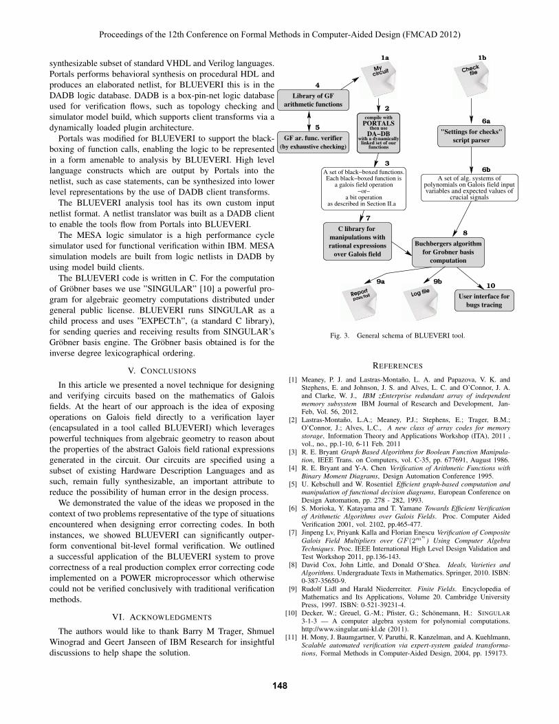
synthesizable subset of standard VHDL and Verilog languages.Portals performs behavioral synthesis on procedural HDL andproduces an elaborated netlist, for BLUEVERI this is in theDADB logic database. DADB is a box-pin-net logic databaseused for verification flows, such as topology checking andsimulator model build, which supports client transforms via adynamically loaded plugin architecture.
Portals was modified for BLUEVERI to support the black-boxing of function calls, enabling the logic to be representedin a form amenable to analysis by BLUEVERI. High levellanguage constructs which are output by Portals into thenetlist, such as case statements, can be synthesized into lowerlevel representations by the use of DADB client transforms.
The BLUEVERI analysis tool has its own custom inputnetlist format. A netlist translator was built as a DADB clientto enable the tools flow from Portals into BLUEVERI.
The MESA logic simulator is a high performance cyclesimulator used for functional verification within IBM. MESAsimulation models are built from logic netlists in DADB byusing model build clients.
The BLUEVERI code is written in C. For the computationof Grobner bases we use ”SINGULAR” [10] a powerful pro-gram for algebraic geometry computations distributed undergeneral public license. BLUEVERI runs SINGULAR as achild process and uses ”EXPECT.h”, (a standard C library),for sending queries and receiving results from SINGULAR’sGrobner basis engine. The Grobner basis obtained is for theinverse degree lexicographical ordering.
V. CONCLUSIONS
In this article we presented a novel technique for designingand verifying circuits based on the mathematics of Galoisfields. At the heart of our approach is the idea of exposingoperations on Galois field directly to a verification layer(encapsulated in a tool called BLUEVERI) which leveragespowerful techniques from algebraic geometry to reason aboutthe properties of the abstract Galois field rational expressionsgenerated in the circuit. Our circuits are specified using asubset of existing Hardware Description Languages and assuch, remain fully synthesizable, an important attribute toreduce the possibility of human error in the design process.
We demonstrated the value of the ideas we proposed in thecontext of two problems representative of the type of situationsencountered when designing error correcting codes. In bothinstances, we showed BLUEVERI can significantly outper-form conventional bit-level formal verification. We outlineda successful application of the BLUEVERI system to provecorrectness of a real production complex error correcting codeimplemented on a POWER microprocessor which otherwisecould not be verified conclusively with traditional verificationmethods.
VI. ACKNOWLEDGMENTS
The authors would like to thank Barry M Trager, ShmuelWinograd and Geert Janseen of IBM Research for insightfuldiscussions to help shape the solution.
1b
6a
6b
8
9a 9b10
7
1a
2
3
5
4
A set of alg. systems of
polynomials on Galois field input
variables and expected values of
crucial signals
script parser
"Settings for checks"
bugs tracing
User interface for
C library for
over Galois field
rational expressions
manipulations withBuchbergers algorithm
for Grobner basis
computation
a galois field operation
−or−
as described in Section II.a
a bit operation
A set of black−boxed functions.
Each black−boxed function is
PORTALScompile with
then use
DA−DBwith a dynamically
linked set of ourfunctions
Library of GF
arithmetic functions
(by exhaustive checking)
GF ar. func. verifier
Checkfile
Report
pass/fail Log file
Mycircuit
Fig. 3. General schema of BLUEVERI tool.
REFERENCES
[1] Meaney, P. J. and Lastras-Montano, L. A. and Papazova, V. K. andStephens, E. and Johnson, J. S. and Alves, L. C. and O’Connor, J. A.and Clarke, W. J., IBM zEnterprise redundant array of independentmemory subsystem IBM Journal of Research and Development, Jan-Feb, Vol. 56, 2012.
[2] Lastras-Montano, L.A.; Meaney, P.J.; Stephens, E.; Trager, B.M.;O’Connor, J.; Alves, L.C., A new class of array codes for memorystorage, Information Theory and Applications Workshop (ITA), 2011 ,vol., no., pp.1-10, 6-11 Feb. 2011
[3] R. E. Bryant Graph Based Algorithms for Boolean Function Manipula-tion, IEEE Trans. on Computers, vol. C-35, pp. 677691, August 1986.
[4] R. E. Bryant and Y-A. Chen Verification of Arithmetic Functions withBinary Moment Diagrams, Design Automation Conference 1995.
[5] U. Kebschull and W. Rosentiel Efficient graph-based computation andmanipulation of functional decision diagrams, European Conference onDesign Automation, pp. 278 - 282, 1993.
[6] S. Morioka, Y. Katayama and T. Yamane Towards Efficient Verificationof Arithmetic Algorithms over Galois Fields. Proc. Computer AidedVerification 2001, vol. 2102, pp.465-477.
[7] Jinpeng Lv, Priyank Kalla and Florian Enescu Verification of CompositeGalois Field Multipliers over GF (2m
n) Using Computer Algebra
Techniques. Proc. IEEE International High Level Design Validation andTest Workshop 2011, pp.136-143.
[8] David Cox, John Little, and Donald O’Shea. Ideals, Varieties andAlgorithms. Undergraduate Texts in Mathematics. Springer, 2010. ISBN:0-387-35650-9.
[9] Rudolf Lidl and Harald Niederreiter. Finite Fields. Encyclopedia ofMathematics and Its Applications, Volume 20. Cambridge UniversityPress, 1997. ISBN: 0-521-39231-4.
[10] Decker, W.; Greuel, G.-M.; Pfister, G.; Schonemann, H.: SINGULAR3-1-3 — A computer algebra system for polynomial computations.http://www.singular.uni-kl.de (2011).
[11] H. Mony, J. Baumgartner, V. Paruthi, R. Kanzelman, and A. Kuehlmann,Scalable automated verification via expert-system guided transforma-tions, Formal Methods in Computer-Aided Design, 2004, pp. 159173.
Proceedings of the 12th Conference on Formal Methods in Computer-Aided Design (FMCAD 2012)
148148148