formal tools: introduction to uml - university of …€¦ · unified modelling language (uml) ......
TRANSCRIPT

© 2012-2013 Elena Punskaya Cambridge University Engineering Department
Diagrams are Useful• Can help you win a cocktail making contest!
!2
source: The Pragmatic Programmer, Andrew Hunt and David Thomas
© 2012-2013 Elena Punskaya Cambridge University Engineering Department
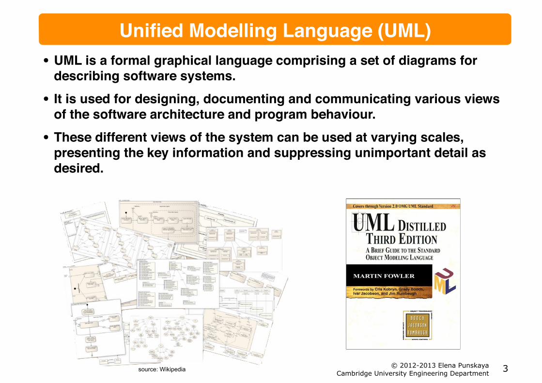
Unified Modelling Language (UML)• UML is a formal graphical language comprising a set of diagrams for
describing software systems.!
• It is used for designing, documenting and communicating various views of the software architecture and program behaviour.!
• These different views of the system can be used at varying scales, presenting the key information and suppressing unimportant detail as desired.
!3source: Wikipedia

© 2012-2013 Elena Punskaya Cambridge University Engineering Department
Brief History• UML evolved from notations used in three earlier rival approaches
independently developed between 1989 and 1994.!- Booch method- Object Oriented Software Engineering- Object Modelling Technique
• All three of them (‘three amigos’) got involved in Rational Software – the company that produced a development framework (tools, processes and services)!
• UML was developed as the notation for Rational Unified Process (RUP) and was released by the Object Management Group, a consortium that was setup to establish Object-Oriented standards and was founded by the likes of DEC, HP, IBM, Microsoft, Oracle, and Texas Instruments.!
• Complete version of UML (V1.1) was released in 1997 and has been since managed by OMG!
• Current version is 2.4.1 (released Aug 2011)!
• “In Process” version 2.5 (released Oct 2012)
!4

© 2012-2013 Elena Punskaya Cambridge University Engineering Department
UML Diagrams and Modes• To describe a system we need to communicate !
- structures: items, and how they are connected !- behaviour: how items interact!
• In UML, structures are described by Class Diagrams!
• Class diagrams describe the software architecture of the system by specifying what classes are present in the system, and their relationships!
• Behaviour diagrams show interactions between Objects, most commonly as Sequence and Communication Diagrams!
• There are many more types of diagrams but these 3 types are the most practical ones!
• Martin Fowler observes that UML can be used “AsSketch”, “AsBlueprint” and “AsProgrammingLanguage” with “AsSketch” being the most popular mode!
‣ http://martinfowler.com/bliki/UmlMode.html"
• The key property of using “UmlAsSketch” is communicating parts of the system in a group of people
!5

© 2012-2013 Elena Punskaya Cambridge University Engineering Department
State of the Art• 14 types are defined in UML 2.2
!6
source: Wikipedia

© 2012-2013 Elena Punskaya Cambridge University Engineering Department
Class Diagram• These show the classes in a software system, their attributes and
operations and their relationships!"
"
"
"
• This diagram says the following!
• The system consists of a Bank that manages “0 or more” Accounts!
• Each Account can be owned by 1 Person and each Person can own “1 or more” Accounts!
• An Account has account number and can calculate interest!
• A Person has a name and can be contacted
!7

© 2012-2013 Elena Punskaya Cambridge University Engineering Department
Class Diagrams• Each class is represented by a
box split into three sections!- name - attributes - operations/methods
• The visibility of the attribute or method is noted by!
- “+” for public, i.e. accessible by any other object
- “-” for private, i.e. internally used attributes and methods
• Mostly only public features of the class are useful to represent as they define interactions and relationships with other classes
!8

© 2012-2013 Elena Punskaya Cambridge University Engineering Department
Point of View• In design and communication of ideas the right level of abstraction
should be used in order to keep diagrams useful!"
"
"
"
"
"
"
"
• It is common to drop the visibility indicator and assume that all shown attributes and methods are public!
• Omitting any methods/attributes all together allows to focus on class relationships
!9
higher abstraction
= Bank has “0 or more” Customers
= Bank manages “0 or more” Accounts. Each Account is owned by 1 Person and each Person can own “1 or more” Accounts

© 2012-2013 Elena Punskaya Cambridge University Engineering Department
Class Relationships• Objects will often contain references (connections) to other objects. For
example, a VideoFrame might contain a reference to a Time object rather than just an int to represent the timestamp !
• This could be shown in a class definition!"
"
• However, more usefully, it maybe shown as an association
!10
© 2012-2013 Elena Punskaya Cambridge University Engineering Department
Association"
"
"
"
"
"
"
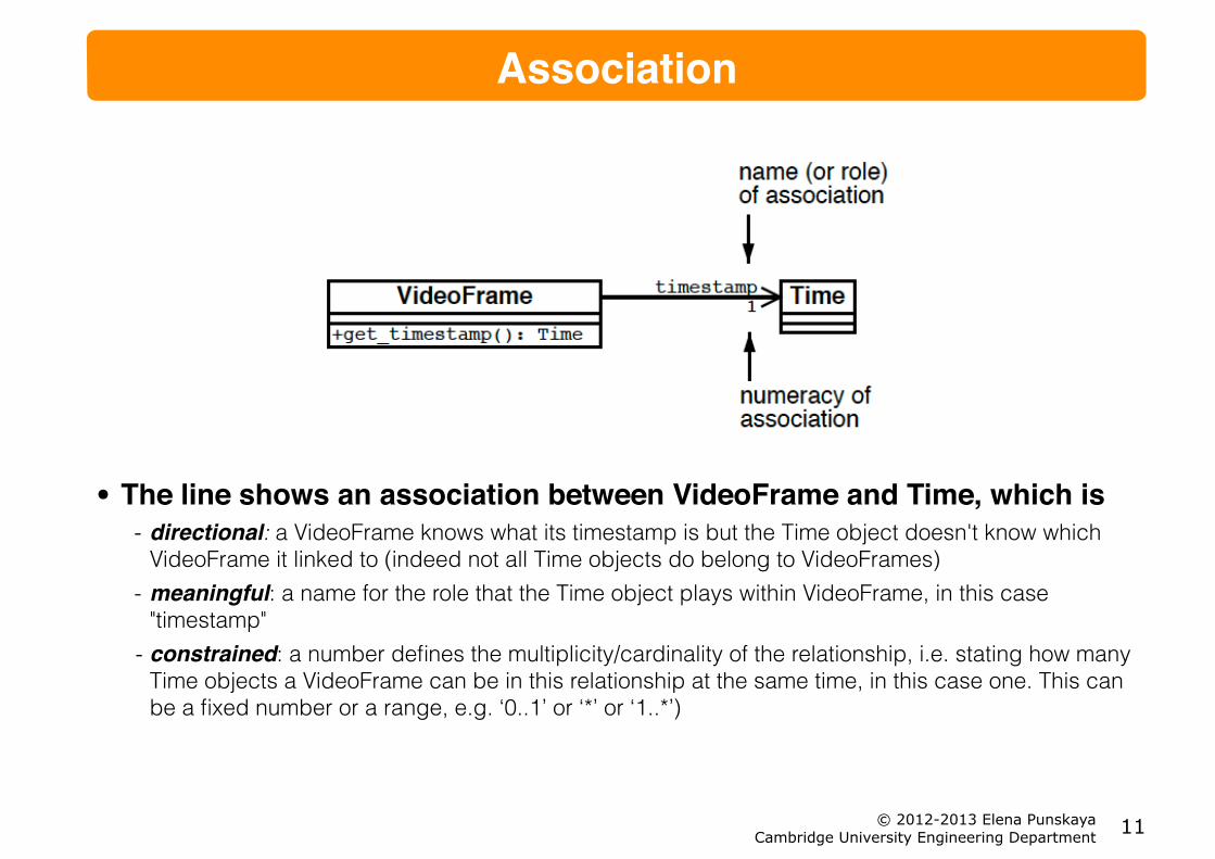
• The line shows an association between VideoFrame and Time, which is!- directional: a VideoFrame knows what its timestamp is but the Time object doesn't know which
VideoFrame it linked to (indeed not all Time objects do belong to VideoFrames) - meaningful: a name for the role that the Time object plays within VideoFrame, in this case
"timestamp" - constrained: a number defines the multiplicity/cardinality of the relationship, i.e. stating how many
Time objects a VideoFrame can be in this relationship at the same time, in this case one. This can be a fixed number or a range, e.g. ‘0..1’ or ‘*’ or ‘1..*’)
!11

© 2012-2013 Elena Punskaya Cambridge University Engineering Department
Navigability• Associations can also show bidirectional navigability. For example,
consider the relationship between lecturers and lecture courses in a timetabling application!"
"
"
"
• This shows that each Lecturer object knows about all the courses they are teaching and that each Course knows which lecturer is in charge. The * indicates that a lecturer may be in charge of any number of courses (including none)!
• The direction of associations is often not shown if it does not add to the meaning of the diagram, e.g. at the conceptual diagram abstraction level
!12

© 2012-2013 Elena Punskaya Cambridge University Engineering Department
Composition• UML also allows a class association to be adorned with a diamond. Not
all users of UML employ this, however, it is useful to know the meaning.!
• A filled diamond denotes Composition!"
"
"
• If A is a House and B is a Room, then Composition relationship means that a Room cannot exist without a House, i.e. it will be destroyed if the House is destroyed!"
"
"
• Composition is potentially useful to emphasise the strength of the relationship between classes, e.g. an exclusive ownership
!13

© 2012-2013 Elena Punskaya Cambridge University Engineering Department
Aggregation• An empty diamond denotes Aggregation and indicates that objects of class
A contain objects of class B, i.e. B is a part of A!
• A does not however control the lifecycle of object of class B!"
"
"
• A College Society can have a number of member Students, but it would be unreasonable to “destroy” students if the Society was to be closed
!14
“Aggregation is strictly meaningless; as a result, I recommend that you ignore it in your own diagrams.” "
UML Distilled , Martin Fowler

© 2012-2013 Elena Punskaya Cambridge University Engineering Department
Inheritance• As we discussed before, Inheritance and Polymophism are the key
features of Object Orientation that allow us to design extensible systems!
• In UML, Inheritance relationship between classes is represented as follows
!15
/ abstract
Using Italics to signify abstract methods is a bit difficult in hand-writing – marking a method/class {abstract} is a valid alternative

© 2012-2013 Elena Punskaya Cambridge University Engineering Department
Interfaces• There are two cases when Inheritance is useful!-Implementation inheritance – the superclass implements some
functionality that can be re-used by all of its subclasses!-Behaviour inheritance when a class can expose a certain set of functionality!
• Interfaces are used to define behavioural inheritance and denoted in UML as!"
"
"
• or, more fully
!16

© 2012-2013 Elena Punskaya Cambridge University Engineering Department
Interfaces Example• Defining the same functionality/ behaviour to very different concepts!
• Example: can we compare Apples and Oranges?!"
"
"
"
"
• Yes, we can! – if Apples and Oranges “know” how to compare!"
"
"
• Of course, the tricky part is how the comparison is made :)
!17
IComparable apple = new Apple();! IComparable orange = new Orange();!" apple.compareTo(orange);
© 2012-2013 Elena Punskaya Cambridge University Engineering Department
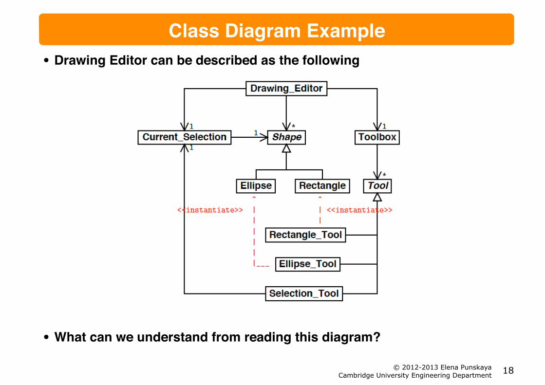
Class Diagram Example• Drawing Editor can be described as the following!"
"
"
"
"
"
"
"
"
"
"
• What can we understand from reading this diagram?
!18

© 2012-2013 Elena Punskaya Cambridge University Engineering Department
Class Diagram Example• Drawing Editor provides 1 (and
only 1) Toolbox!
• Toolbox consists of “0 or more” Tools!
• There are three types of tools that are used to create Rectangles, Ellipses and make a Selection!
• Drawing editor can show “0 or more” Shapes. There are two types of shapes: Ellipse and Rectangle!
• Drawing Editor maintains the Current Selection!
• Only 1 shape can be selected at a time. Selection Tool makes the Current Selection which includes Shape
!19
maintains
makesincludes
shows provides
consists of

© 2012-2013 Elena Punskaya Cambridge University Engineering Department
Dynamic View• Class diagrams are very useful to capture the relationships, but this is
only one part of a story – this is only a list of ingredients from a recipe, but to make a dish we need to know how to put them together!
• To understand how the system works (and validate the design) we need to understand how objects interact with each other for a purpose of a particular action!
• There are two main types of UML diagrams that capture interactions!- Sequence Diagrams!- Collaboration/Communication Diagrams!
• Both could be used for exactly same purposes!
• Sequence Diagrams present a more clear view of the timeline, therefore could be particularly helpful to capture the logic flow!
• Communication Diagrams can focus more on the nature of collaboration between the object to perform an action
!20

© 2012-2013 Elena Punskaya Cambridge University Engineering Department
Sequence Diagram• Consider the drawing Editor example!"
"
"
"
• Suppose the drawing consists of two rectangles and the display() method is called on the DrawingEditor. The series of calls that take place can be shown in a sequence diagram:
!21

© 2012-2013 Elena Punskaya Cambridge University Engineering Department
Sequence Diagram• This diagram shows three objects. These are: one object of type Drawing
Editor called adrawing and two objects of type Rectangle called rectangle1 and rectangle2. The vertical axis of this diagram corresponds to time (traveling downward). The white boxes show the duration of each call. This diagram explicitly shows the return from the two draw() calls with dashed lines although these are often omitted!"
"
"
"
"
"
"
• UML defines additional notation (e.g. object deletion/creation) – rarely used
!22
1. display() is called in adrawing
2. adrawing calls the clear screen() method in itself
3. This method returns
4. adrawing calls the draw() method in rectangle1.
5. This method returns.
6. adrawing calls the draw() method in rectangle2
7. This method returns.
8. The display() method is completed and returns

© 2012-2013 Elena Punskaya Cambridge University Engineering Department
Communication Diagram
• Communication diagrams show the method flow between objects by numbering method calls!"
"
"
"
"
"
"
"
• Both diagram types capture the dynamic behaviour of the system in a specific scenario!
- Sequence diagrams are easier to read when there are a few objects with potentially a lot of calls - Communication diagrams are easier to read when there are a few method calls between potentially
many objects
!23

© 2012-2013 Elena Punskaya Cambridge University Engineering Department
State Diagrams• Sometimes the behaviour of a single object depends on its state, UML
offers State Diagrams to capture it!"
"
"
"
"
"
"
"
"
"
• The need for such diagrams is more common in e.g. Embedded Software development
!24

© 2012-2013 Elena Punskaya Cambridge University Engineering Department
UML Summary• UML is a notation that helps to capture, share and validate design
concepts!
• It can be used in conjunction with formal software processes (e.g. RUP), where even source code can be generated from UML diagrams!
• The main strength is however in the ability to describe the static and dynamic view of the system in the common way!
- Class and Sequence (Communication) diagrams are by far the most used parts of UML
• Using UML as a basis, project teams can adapt and extend it to their need, but creating new types of diagrams, modifying the notation etc. is OK, as long as:!
- everyone on the project can understand it - everyone’s understanding is the same ;)
!25
aBank
James